WO2020171209A1 - 高強度電縫鋼管および地盤安定化工事用高強度電縫鋼管の使用方法 - Google Patents
高強度電縫鋼管および地盤安定化工事用高強度電縫鋼管の使用方法 Download PDFInfo
- Publication number
- WO2020171209A1 WO2020171209A1 PCT/JP2020/007101 JP2020007101W WO2020171209A1 WO 2020171209 A1 WO2020171209 A1 WO 2020171209A1 JP 2020007101 W JP2020007101 W JP 2020007101W WO 2020171209 A1 WO2020171209 A1 WO 2020171209A1
- Authority
- WO
- WIPO (PCT)
- Prior art keywords
- steel pipe
- dcave
- strength
- deave
- outer diameter
- Prior art date
- Legal status (The legal status is an assumption and is not a legal conclusion. Google has not performed a legal analysis and makes no representation as to the accuracy of the status listed.)
- Ceased
Links
Images







Classifications
-
- C—CHEMISTRY; METALLURGY
- C21—METALLURGY OF IRON
- C21D—MODIFYING THE PHYSICAL STRUCTURE OF FERROUS METALS; GENERAL DEVICES FOR HEAT TREATMENT OF FERROUS OR NON-FERROUS METALS OR ALLOYS; MAKING METAL MALLEABLE, e.g. BY DECARBURISATION OR TEMPERING
- C21D8/00—Modifying the physical properties of ferrous metals or ferrous alloys by deformation combined with, or followed by, heat treatment
- C21D8/02—Modifying the physical properties of ferrous metals or ferrous alloys by deformation combined with, or followed by, heat treatment during manufacturing of plates or strips
-
- C—CHEMISTRY; METALLURGY
- C21—METALLURGY OF IRON
- C21D—MODIFYING THE PHYSICAL STRUCTURE OF FERROUS METALS; GENERAL DEVICES FOR HEAT TREATMENT OF FERROUS OR NON-FERROUS METALS OR ALLOYS; MAKING METAL MALLEABLE, e.g. BY DECARBURISATION OR TEMPERING
- C21D9/00—Heat treatment, e.g. annealing, hardening, quenching or tempering, adapted for particular articles; Furnaces therefor
- C21D9/46—Heat treatment, e.g. annealing, hardening, quenching or tempering, adapted for particular articles; Furnaces therefor for sheet metals
-
- C—CHEMISTRY; METALLURGY
- C22—METALLURGY; FERROUS OR NON-FERROUS ALLOYS; TREATMENT OF ALLOYS OR NON-FERROUS METALS
- C22C—ALLOYS
- C22C38/00—Ferrous alloys, e.g. steel alloys
-
- C—CHEMISTRY; METALLURGY
- C22—METALLURGY; FERROUS OR NON-FERROUS ALLOYS; TREATMENT OF ALLOYS OR NON-FERROUS METALS
- C22C—ALLOYS
- C22C38/00—Ferrous alloys, e.g. steel alloys
- C22C38/06—Ferrous alloys, e.g. steel alloys containing aluminium
-
- C—CHEMISTRY; METALLURGY
- C22—METALLURGY; FERROUS OR NON-FERROUS ALLOYS; TREATMENT OF ALLOYS OR NON-FERROUS METALS
- C22C—ALLOYS
- C22C38/00—Ferrous alloys, e.g. steel alloys
- C22C38/18—Ferrous alloys, e.g. steel alloys containing chromium
- C22C38/40—Ferrous alloys, e.g. steel alloys containing chromium with nickel
- C22C38/58—Ferrous alloys, e.g. steel alloys containing chromium with nickel with more than 1.5% by weight of manganese
-
- E—FIXED CONSTRUCTIONS
- E02—HYDRAULIC ENGINEERING; FOUNDATIONS; SOIL SHIFTING
- E02D—FOUNDATIONS; EXCAVATIONS; EMBANKMENTS; UNDERGROUND OR UNDERWATER STRUCTURES
- E02D5/00—Bulkheads, piles, or other structural elements specially adapted to foundation engineering
- E02D5/22—Piles
- E02D5/24—Prefabricated piles
- E02D5/28—Prefabricated piles made of steel or other metals
Definitions
- the present invention provides a high-strength electric resistance welded steel pipe used for perforating the soil and improving the ground on a slope or the ground in the ground stabilization work (including tunnel work or ground stabilization work) and the ground stabilization work height.
- a method for using a high strength electric resistance welded steel pipe is disclosed.
- Patent Document 1 and Patent Document 2 disclose a technique of increasing the tensile strength by heating the pipe to a high temperature and then rapidly cooling it. Further, for example, in Patent Document 3, by adjusting the chemical composition, the yield strength, the tensile strength, and the yield ratio of the electric resistance welded steel pipe for oil wells, which is a type of steel pipe buried in the ground, to a specific range, respectively. , A technique for improving tensile strength and toughness without heat treatment after pipe making is disclosed.
- the steel pipe for the above-mentioned application has male and female threads on both pipe ends in advance after pipe making at a steel pipe manufacturing factory, or at a middleman or at a construction site of a construction site, or a connecting member having a connecting function. It is necessary to join both ends or one end of the steel pipe, carry it to the construction site, and then connect the drilling tool and the steel pipe, or the steel pipes to each other at the construction site for use.
- adult men should try to keep the weight of what they handle manually by 40% or less of their weight.
- the weight of an adult male is 70 kgf
- the weight that can be handled by one person is 28 kgf. Therefore, the conventional steel pipe cannot be handled by one worker, and there is a demand for weight reduction of the steel pipe from the viewpoint of difficulty in securing the worker, labor cost, and the like.
- the high-strength steel pipe for ground stabilization work of the present application is manufactured in a pipe manufacturing factory with a length of about 10 m or longer in view of production efficiency and price, and the above-mentioned is done by an intermediate company. After cutting to a predetermined length, thread cutting etc. is carried in, and it is carried into the construction site and constructed.
- thread cutting etc. is carried in, and it is carried into the construction site and constructed.
- the steel pipe is pushed horizontally or slightly obliquely, or laterally, so if welding is used, welding will be performed at the construction site while maintaining linearity while maintaining the linearity. It is extremely difficult to prepare such a welding device.
- Examples of applications of steel pipes or high-strength steel pipes with a length close to that of high-strength steel pipes for ground stabilization work include automotive applications such as torsion beams and structural members, and scaffolding members at construction sites. Mechanical joining such as welding or bolting is the mainstream for joining with other members in automobile applications, and threading that affects the roundness is rarely used, and the problem of this application does not become apparent. .. This is the same for scaffolding members at construction sites, which are assembled by fastening with metal fittings.
- thread cutting for example, there is a steel pipe for oil well pipes, but this is for a steel pipe with a long material of about 10 m and a roundness secured at a pipe manufacturing factory, it is threaded by an intermediate company before or after shipping, and it is shipped. It is used by connecting the length of time.
- a short material for several meters may be threaded by an intermediary company for length adjustment, but this is only a small part, and there is only a slight change in shape and true cutting. Issues related to circularity do not become apparent.
- the inventors of the present invention used a high-strength electric resistance welded steel pipe that is lightweight and high-strength and has a high roundness at the end of the steel pipe generated by new cutting after pipe making and a high-strength electric resistance welded steel pipe for ground stabilization work. Provide a way.
- the high-strength electric resistance welded steel pipe according to one aspect of the present invention has a mass% or mass ppm of C: 0.04 to 0.30%, Si: 0.01 to 2.00%, and Mn: 0.50.
- YN MAX[ ⁇ DEave ⁇ ( ⁇ 2/100) ⁇ , ⁇ -4 ⁇ ((tEave/3) ⁇ 0.65) ⁇ ] (5)
- the larger one of ⁇ DEave ⁇ ( ⁇ 2/100) ⁇ and ⁇ 4 ⁇ ((tEave/3) ⁇ 0.65) ⁇ is defined as YN.
- the tensile strength may be 780 N/mm 2 or more.
- the following formula may be further satisfied.
- the following formula may be further satisfied.
- the method of using the high-strength electric resistance welded steel pipe for ground stabilization work according to one aspect of the present invention is generated by cutting the high-strength electric resistance welded steel pipe according to (1) or (2) at the central portion of the steel pipe.
- the new steel pipe end is threaded, and two or more high strength ERW steel pipes are connected with a threaded joint for use.
- the method for using the high-strength electric resistance welded steel pipe for ground stabilization work according to one aspect of the present invention is such that one or both of the steel pipe end portions of the high-strength electric resistance welded steel pipe according to (1) or (2) above are used.
- Two or more high-strength electric resistance welded steel pipes are connected to new steel pipe ends generated by cutting at the central portion of the steel pipe by fitting the steel pipe ends to each other through one or a plurality of jigs.
- a method of using a high-strength electric resistance welded steel pipe having a light weight and high strength, and a steel pipe end portion generated by a new cutting after pipe making has a high roundness and a high strength electric resistance welded steel pipe for ground stabilization work.
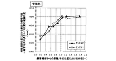
- Le determines the range of the central part of the steel pipe, and is the distance from the end of the steel pipe/the outer diameter at that position, the longitudinal ellipticity of the cross section at the outer diameter measurement position, and the length of the steel pipe in the pipe forming direction. It is a figure showing the relationship of the difference of the vertical ellipticity of the 1/2 position.
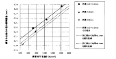
- the steel pipe has an outer diameter of 114.3 mm, a wall thickness of 3.5 mm, and a length of 7,400 mm. It is a figure showing the tensile strength of a steel pipe, and the relation of longitudinal ellipticity ( ⁇ DE) of a steel pipe end-vertical ellipticity ( ⁇ DC) of a steel pipe central part.
- the steel pipe has an outer diameter of 114.3 mm and a wall thickness of 3.2 to 8.6 mm. It is a figure showing the tensile strength of a steel pipe for every plate thickness, and the relation of longitudinal ellipticity (deltaDE) of a steel pipe end-vertical ellipticity (deltaDC) of a steel pipe central part.
- the outer diameter of the steel pipe is 114.3 mm. It is a figure showing the relationship between the tensile strength of a steel pipe and the standard deviation of the average outer diameter of a steel pipe center part.
- the steel pipe has an outer diameter of 114.3 mm and a wall thickness of 3.2 to 8.6 mm.
- the outer diameter of the steel pipe is 114.3 mm. It is a figure which shows the relationship of the tensile strength of a steel pipe and the residual stress of a steel pipe center part.
- the steel pipe has an outer diameter of 114.3 mm and a wall thickness of 3.2 to 8.6 mm. It is the figure which showed typically the change of the average outer diameter of a steel pipe end when a steel pipe end deform
- FIG. 1 shows the vertical ellipticity (DELTA)DC of the central part (before cutting) of a steel pipe, and the vertical ellipticity (DELTA)DE of a steel pipe end (after cutting) when joining a steel pipe end by fitting.
- DELTA vertical ellipticity
- DELTA vertical ellipticity
- the inventors measured the steel pipe cross-sectional dimension of the steel pipe central portion before and after cutting when the steel pipe central portion was cut to a predetermined length after pipe making, and the steel pipe cross-sectional dimension due to the residual stress being released by the steel pipe cutting.
- the changes in the above were investigated in detail.
- the cross-sectional shape of the steel pipe before cutting is achieved by adjusting the roll position of each roll stand in the pipe forming step, welding step, and straightening step.
- the manufacturing conditions cannot be unconditionally specified because each process condition is slightly different depending on the specifications of the pipe making equipment, such as the number of roll stages, the rolling force, the roll profile and their arrangement. It can be carried out by finding and adjusting the process conditions suitable for the pipe making equipment by appropriately measuring the dimensions and confirming the roundness after the pipe making. Most of the steel pipes are cut by sawing, but may be cut by a lathe. In the present specification, the "high-strength electric resistance welded steel pipe" may be simply referred to as "steel pipe”. Further, in the present specification, the numerical range represented by “to” means a range including the numerical values before and after “to” as the lower limit value and the upper limit value.
- the high-strength electric resistance welded steel pipe according to the present embodiment has C: 0.04 to 0.30%, Si: 0.01 to 2.00%, Mn: 0.50 to 3.00% in mass% or mass ppm.
- the outer diameter (DCave described later) of the steel pipe is 60.3 mm or more and 318.5 mm or less.
- the outer diameter of the steel pipe is 60.3 mm or more, the strength of the steel pipe as the object of the present invention is easily obtained. If the outer diameter of the steel pipe is 318.5 mm or less, it is easy to carry.
- the outer diameter of the steel pipe is preferably 113 mm or more and 116 mm or less.
- the outer diameter of the steel pipe is an average outer diameter.
- the ratio (tCave/DCave) between the wall thickness of the steel pipe (tCave described below) and the outer diameter of the steel pipe (DCave described below) is 0.02 or more and 0.06 or less. When the ratio (tCave/DCave) between the wall thickness of the steel pipe and the outer diameter of the steel pipe is 0.02 or more, the strength of the steel pipe is easily achieved.
- the tensile strength of the steel pipe is 590 N/mm 2 or more. When the tensile strength is 590 N/mm 2 or more, the wall thickness can be reduced and the weight can be easily carried by hand.
- the tensile strength is preferably 780 N/mm 2 or more.
- Tensile strength is preferably 1200 N / mm 2, more preferably not more than 1500 N / mm 2.
- the yield ratio of the steel pipe is preferably 86% or more and 99% or less because the joint strength of the screw increases.
- the tensile strength and the yield ratio of the steel pipe can be obtained by taking a full-thickness test piece in the pipe axial direction from the base material portion of the steel pipe after pipe making and performing a tensile test in the pipe axial direction.
- the welded portion is placed at 12 o'clock of the timepiece, its position is 0°, an arbitrary outer diameter within a range of ⁇ 45° is D1, and a diameter orthogonal to D1 is D3.
- the diameter at a position of 45° clockwise from D1 is D2, and the diameter at a position of 45° clockwise from D3 is D4.
- the outer diameters of the steel pipe central portions in D1, D2, D3, and D4 are DC1, DC2, DC3, and DC4, respectively, and the average thereof is the average outer diameter of the steel pipe central portion and is called DCave.
- the inner diameters of the central portions of the steel pipes at the positions D1, D2, D3, D4 are respectively dC1, dC2, dC3, dC4, and the average thereof is referred to as the average inner diameter of the central portions of the steel pipes, dCave, and D1, D2, D3, D4.
- the thickness of the central portion of the steel pipe at the position of is defined as tC1, tC2, tC3, and tC4, and the average thereof is defined as the average thickness of the central portion of the steel pipe, which is referred to as tCave.
- the units of DC1, DC2, DC3, DC4, dC1, dC2, dC3, dC4, tC1, tC2, tC3, tC4, DCave, dCave, and tCave are all mm.
- the welded portion is placed at 12 o'clock and its position is set to 0°, and an arbitrary outer diameter within a range of ⁇ 45° is set to D1, and a diameter orthogonal to D1 is set to D3. ..
- the diameter at a position of 45° clockwise from D1 is D2, and the diameter at a position of 45° clockwise from D3 is D4.
- the outer diameters of the steel pipe ends in D1, D2, D3, and D4 are DE1, DE2, DE3, and DE4, and the average thereof is the average outer diameter of the steel pipe ends and is called DEave.
- the inner diameters of the steel pipe ends at the positions of D1, D2, D3, D4 are dE1, dE2, dE3, dE4, and the average thereof is the average inner diameter of the steel pipe ends, dEave, and the steel pipes at the positions of D1, D2, D3, D4.
- the wall thicknesses of the end portions are tE1, tE2, tE3, and tE4, and the average thereof is the average wall thickness of the steel pipe end portion and is called tEave.
- the units of DE1, DE2, DE3, DE4, dE1, dE2, dE3, dE4, tE1, tE2, tE3, tE4, DEave, dEave, and tEave are all mm.
- the part separated to the side is the central part of the steel pipe.
- the central portion of the steel pipe is a range in which the residual stress generated during pipe forming is released when the steel pipe is cut, and the cross-sectional dimension of the steel pipe is deformed.
- An example thereof is shown in FIG.
- the horizontal axis of FIG. 1 is “distance from steel pipe end/outer diameter at that position”.
- the vertical axis represents the “difference between the vertical ellipticity of the cross section at the outer diameter measurement position and the vertical ellipticity of the length 1/2 position in the pipe forming direction”.
- the distance from the steel pipe end/outer diameter at that position” on the horizontal axis is greater than 1.0, that is, the distance from the cutting position of the steel pipe end is the outer diameter of the steel pipe toward the center in the longitudinal direction of the steel pipe.
- the distance from the center of the steel pipe is larger than the position Le, that is, at the center of the steel pipe before cutting, "vertical ellipticity of the cross section at the outer diameter measurement position and vertical ellipse at a position of 1/2 length in the length direction of the steel pipe"
- the difference in degree" is almost 0, which means that the longitudinal ellipticity is the same with respect to the 1/2 position in the length direction of the steel pipe and the steel pipe is not deformed.
- the horizontal axis is 1.0 or less, that is, the steel pipe end portion side from the position Le distant from the cutting position of the steel pipe end portion by the outer diameter of the steel pipe toward the central portion in the longitudinal direction of the steel pipe is “outer diameter”.
- the difference between the vertical ellipticity of the cross section at the measurement position and the vertical ellipticity at the 1/2 position in the pipe-making direction fluctuates in the negative direction. This means that when the steel pipe is cut into the steel pipe end, the residual stress is released, the deformation of the steel pipe end increases, and the roundness deteriorates.
- the cutting position of the steel pipe is the position cut for product collection in the middle of pipe making, at both ends of the steel pipe product at the time of shipping after pipe making, at an intermediate company, or at the construction site of the construction site. It also includes the ends of steel pipes obtained by cutting.
- K is a constant calculated by the following equation (6).
- K ⁇ +( ⁇ /I)+( ⁇ TS) ⁇ DCave (6)
- TS is the tensile strength (N/mm 2 ) of the steel pipe base material
- ⁇ , ⁇ and ⁇ are constants
- ⁇ -1.87 ⁇ 10 ⁇ 3
- ⁇ 1.35 ⁇ 10 4
- ⁇ ⁇ 6.65 ⁇ 10 ⁇ 6
- I is the second moment of area (mm 4 ) of the cross section of the central portion of the steel pipe, and is derived by the following equation (12).
- I ⁇ /64 ⁇ (DCave) 4 ⁇ (DCave-2 ⁇ tCave) 4 ⁇ (12)
- FIG. 3 shows an example of the calculation result of the equation (21) for each plate thickness.
- Standard deviation of the average outer diameter of the central portion of the steel pipe ⁇ p+(q/I)+(r ⁇ TS) ⁇ DCave ( 8)
- TS is the tensile strength (N/mm 2 ) of the steel pipe base material
- p, q, and r are constants
- p 1.39 ⁇ 10 ⁇ 3
- q 4.17 ⁇ 10 2
- r It is 6.05 ⁇ 10 ⁇ 7
- I is the second moment of area (mm 4 ) of the cross section of the central portion of the steel pipe, which is derived from the above-mentioned equation (12).
- FIG. 5 shows an example of the calculation result of the formula (8) for each plate thickness.
- the steel pipe for the said use has two usage methods when connecting and using a plurality of steel pipes.
- One is a method in which male and female threads are directly threaded on both ends of a steel pipe using a rotary cutting device and the steel pipes are connected and used.
- the other is that one or more jigs are used between the steel pipes. It is a method of fitting and connecting to the end of the steel pipe.
- the steel pipe end part is also provided with one or more jigs between the steel pipes.
- the fitting method in order to secure the strength on the fitting surface, it is necessary to secure a high roundness as well as the outer diameter tolerance of the steel pipe at the pipe end.
- the higher the strength the higher the strength of the steel pipe. Has a high residual stress.
- the residual stress is released to the end of the steel pipe near the cutting position, the force of deformation acts, and the thin wall is more likely to be deformed, and the change in longitudinal ellipticity at the pipe end tends to be large. Securing becomes an issue.
- the residual stress is measured by the Crumpton method (for example, described in Nippon Steel & Sumikin Technical Report No. 397 (2013) p31).
- Fig. 7 shows that when threading is directly performed on the end of the steel pipe, the cross section becomes vertically long (vertical ellipticity> 0) compared to the case where the design values of threading, that is, the outer diameter and the wall thickness are average values.
- both male and female threads have a residual portion that is not cut with respect to the average wall thickness. It is necessary to make the residual thickness as small as possible while ensuring the soundness and soundness of the screw shape, and it is required to set the vertical ellipticity of the steel pipe end within a certain range.
- the inventors clarified the relationship between the longitudinal ellipticity of the central portion of the steel pipe and the longitudinal ellipticity of the steel pipe end when the tensile strength and the size are different, based on the above new knowledge, that is, the steel pipe has a predetermined length L.
- a method has been found in which the steel pipe end portion after cutting the steel pipe has a high roundness by setting the longitudinal ellipticity of the central portion and the steel pipe end portion after cutting within a predetermined range.
- an area AA is an area required to secure the outer diameter tolerance, and is an area surrounded by points A1, A2, A3, and A4 in FIG.
- the outer diameter tolerance (tolerance 1) ⁇ 1% specified by JIS G 3444 (2016) structural steel pipe is satisfied.
- the outer diameter tolerance may be changed according to the standard. This range is a necessary condition to secure the necessary circular shape when used as a structural pipe.If this is not satisfied, the bending moment required for the structural steel pipe is secured and the bending obtained from it. Proof strength and buckling resistance cannot be maintained. This range is a range necessary to ensure the function as a structural pipe.
- points A1 to A4 satisfy the following expressions (24) to (31).
- Point A2: x(A2) DCave ⁇ (2/100) (26)
- y(A2) DEave ⁇ ( ⁇ 2/100)
- Point A3: x(A3) DCave ⁇ ( ⁇ 2/100) (28)
- y(A3) DEave ⁇ ( ⁇ 2/100)
- Point A4: x(A4) DCave ⁇ ( ⁇ 2/100) (30)
- y(A4) DEave ⁇ (2/100) (31)
- the area AA is (x, y) that simultaneously satisfies the following expressions (32) and (33).
- the region YY is the range of the shape of the pipe end that should be secured in order to secure the necessary screw function while reducing the residual thickness as much as possible in the thread cutting process to reduce the weight of the steel pipe.
- the inventors have calculated the average residual thickness schematically shown in FIG. Average remaining meat ⁇ tEave/3 (34) I found that. If the residual thickness is less than this, it is considered that the joint strength required for the tubular body cannot be ensured, and the function as the original application such as breakage of the joint portion during use cannot be ensured.
- the residual thickness limit is Marginal residual thickness ⁇ 0.65 mm (35) I found that. If this value is less than this value, there will be problems in manufacturing and usage, such as an increase in manufacturing cost due to defective products due to deformation of the screw part during processing, and inability to use due to deformation of the screw part during product use. There are cases.
- Fig. 7 shows an example of the conditions necessary for the shape of the pipe end to be secured in order to secure the necessary screw function while reducing the residual thickness as much as possible in the thread cutting process to reduce the weight of the steel pipe.
- the male screw side is the following formula (36)
- Marginal residual meat Average residual meat-(dE1-dEave)/2 ⁇ 0.65 (36)
- dEave DEave-2 ⁇ tEave (38) Is.
- the equation (40) becomes the following equation (41), DEave-DE3 ⁇ 2 ⁇ (tEave/3)-0.65 ⁇ (41)
- the male screw side has the following formula (43), DEave-DE1 ⁇ 2 ⁇ (tEave/3)-0.65 ⁇ (43)
- the female screw side has the following formula (44), DE3-DEave ⁇ 2 ⁇ (tEave/3)-0.65 ⁇ (44)
- the following equation (45) DE3-DE1 ⁇ 4 ⁇ (tEave/3)-0.65 ⁇ (45)
- Rewriting equation (45), the following equation (46) ⁇ DE DE1-DE3 ⁇ 4 ⁇ (tEave/3) ⁇ 0.65 ⁇ (46) Becomes
- the x-axis is the vertical ellipticity ⁇ DC of the central portion of the steel pipe
- the y-axis is the vertical ellipticity ⁇ DE of the steel pipe end portion.
- the x-axis component of the point i in the figures is x(i)
- the axis component is expressed as y(i).
- MAX(n,m) represents the larger value of n and m
- MIN(n,m) represents the smaller value of n and m.
- (x, y) that simultaneously satisfies the following formulas (49) and (50) is the region YY. - ⁇ x ⁇ (49) ⁇ 4 ⁇ (tEave/3) ⁇ 0.65 ⁇ y ⁇ 4 ⁇ (tEave/3) ⁇ 0.65 ⁇ (50)
- Region XX which is commonly surrounded by region AA and region YY, that is, the outer diameter tolerance for ensuring the function as a structural pipe is secured, the residual thickness is made as small as possible, and the weight of the steel pipe is reduced, while the required screw
- the region where the function can be secured is the region surrounded by the points X1, X2, X3, and X4, and is expressed by the following equations (51) to (58).
- YN and YM are not shown in FIG. 8, but are as follows.
- the larger value is -0.65.
- .65 is the smaller value, and is the equation (4) and the equation (5).
- YN MAX[ ⁇ DEave ⁇ ( ⁇ 2/100) ⁇ , ⁇ -4 ⁇ ((tEave/3) ⁇ 0.65) ⁇ ]
- YM MIN[ ⁇ DEave ⁇ (2/100) ⁇ , ⁇ 4 ⁇ ((tEave/3) ⁇ 0.65) ⁇ ] (4)
- the inventors clarified the relationship between the central ellipticity of the steel pipe and the longitudinal ellipticity of the steel pipe end as described above, and using this, control the longitudinal ellipticity of the central part of the steel pipe in a certain range in pipe making.
- a method has been found in which the longitudinal ellipticity of the steel pipe end portion after the steel pipe is cut is ensured to be low and thread cutting is possible.
- the method and the area of the product obtained by the method are shown as area PP in FIG. 8 below.
- the region PP is a region in which the above-mentioned region XX and the below-described region WW are overlapped.
- the region WW indicates the range of ⁇ DC and ⁇ DE obtained by manufacturing using the relationship between the longitudinal ellipticity of the central portion of the steel pipe and the longitudinal ellipticity of the steel pipe, including variations.
- the area WW in FIG. 8 will be described.
- y is ⁇ DE and x is ⁇ DC, and when replaced with this, the above-mentioned expression (21) is obtained.
- K is a constant obtained by the above equation (6).
- the standard deviation of the average outer diameter DCave of the central portion of the steel pipe obtained by the above equation (8) is used.
- the region WW is surrounded by WH and the line WL.
- WH represents the upper limit of ⁇ DE which is +3 ⁇ from the average
- WL represents the lower limit of ⁇ DE which is ⁇ 3 ⁇ from the average, and are represented by the following formulas (63) and (64).
- the region PP of FIG. It is the range of possible products, and is the overlapping portion of region XX and region WW.
- the region PP is (x, y) that simultaneously satisfies the following formulas (59), (60) and (3).
- Point P1 An intersection of a line passing through X1 and X2 and a line WL.
- Point P2 An intersection of a line passing through X4 and X3 and a line WH.
- Point Z1 An intersection of a line passing through X4 and X1 and a line WH.
- Point Z3 An intersection of a line passing through X3 and X2 and a line WL.
- the region XX may not be satisfied due to manufacturing variations. Therefore, in the thread cutting process, the range of ⁇ DC to be set in FIG. 9 and the range of ⁇ DE obtained at that time are defined as a more preferable region in which it is possible to stably secure the region XX in consideration of manufacturing variations. Shown as ZZ. Expressed by the formula, the region (ZZ) satisfies the following formula (65) and the formula (3) at the same time. YN-K+3 ⁇ SD ⁇ x ⁇ YM-K-3 ⁇ SD (65) x+K-3 ⁇ SD ⁇ y ⁇ x+K+3 ⁇ SD (3) When this is shown by coordinates in FIG.
- the area ZZ is an area that satisfies the area XX and is surrounded by a line connecting the following four points, point Z1, point Z2, point Z3, and point Z4.
- Point Z1 An intersection of a line passing through X4 and X1 and a line WH, and is represented by the following equations (66) and (67).
- the region YY (the region necessary to secure the necessary screw function while reducing the residual wall as much as possible in the thread cutting process to reduce the weight of the steel pipe) becomes the area AA. It may be larger than (the range required to secure the outer diameter tolerance), and the region PP in that case is shown in FIG.
- the area XX which is the overlap of the area AA and the area YY, is the same as the area AA.
- (x, y) that simultaneously satisfies the following equations (32) and (33) is the region XX and is represented by the following equations (32) and (33).
- the area XX is an area inside the line connecting the following four points X1, X2, X3, and X4, and the following equations (24) to (31) It is expressed by a formula.
- the region WW showing the range of ⁇ DC and ⁇ DE obtained when manufacturing is performed by using the relationship between the vertical ellipticity of the steel pipe central portion and the steel pipe end portion is the same as the above description.
- (X, y) that simultaneously satisfies the above-described expression (3) is the region WW and is expressed by the following expression (3).
- a region PP is a portion where the region XX and the region WW overlap.
- the region PP is (x, y) that simultaneously satisfies the following equations (32), (33) and (3).
- Point P1 An intersection of a line passing through X1 and X2 and a line WL.
- Point P2 An intersection of a line passing through X4 and X3 and a line WH.
- Point Z1 An intersection of a line passing through X4 and X1 and a line WH.
- Point Z3 An intersection of a line passing through X3 and X2 and a line WL.
- FIG. 11 shows a region ZZ which is a more preferable region in which it is possible to stably secure the region XX in consideration of manufacturing variations in this case.
- the area ZZ is an area inside the line connecting the following four points Z1, Z2, Z3, and Z4, which satisfies the area XX and is defined by the following (75 ) To (82).
- Point Z1 An intersection of a line passing through X4 and X1 and a line WH.
- Point Z4: An intersection of x x(Z3) and the line WH.
- the vertical ellipticity of the central portion of the steel pipe is controlled in a certain range in pipe making by using the relationship between the vertical ellipticity of the central portion of the steel pipe and the vertical ellipticity of the end portion of the steel pipe in pipe making.
- a region PP which is a product region obtained by a method of ensuring a low ellipticity, is a portion where the region XX and the region WW overlap. Expressed by an equation, the region PP is (x, y) that simultaneously satisfies the following equations (32), (33) and (3).
- FIG. 13 shows a case where the steel pipe ends are fitted and connected to each other via one or a plurality of jigs to be used by being connected to each other in consideration of manufacturing variations, and the region XX is stably provided.
- a more preferable region ZZ in which the above can be secured is shown.
- the area ZZ is an area that satisfies the area XX and is surrounded by a line connecting the following four points, the point Z1, the point Z2, the point Z3, and the point Z4. It is represented by equations (82).
- Point Z1 An intersection of a line passing through X4 and X1 and a line WH.
- Point Z4: An intersection of x x(Z3) and the line WH.
- the hot-rolled steel sheet used for the high-strength electric resistance welded steel pipe is manufactured by heating the steel having the above-mentioned components, hot rolling, controlled cooling, and winding.
- the heating temperature of steel is preferably 1150° C. or higher in order to solid-dissolve carbide forming elements such as Nb in the steel.
- the heating temperature is too high, the austenite grains become coarse, and as a result, the ferrite grain size becomes coarse, so 1280° C. or lower is preferable.
- the finishing temperature of hot rolling is preferably 850° C.
- the obtained hot-rolled steel sheet is continuously formed into an open pipe by roll forming, and then the end portions of the open pipe are butted to each other by electric resistance welding to manufacture an electric resistance welded steel pipe. Seam heat treatment for heating the electric resistance welded portion and accelerating cooling may be performed. After that, the outer diameter of the steel pipe may be reduced by 0.5% to 4.0% with a sizer.
- Fig. 14 shows an example of the manufacturing process for ERW steel pipe.
- ERW steel pipe is manufactured by cold working with multiple roll stands, forming process to bend steel sheet into C section, welding process to sew the pipe end, and straightening process to adjust the shape by slightly reducing the pipe diameter.
- the AA' cross section is the stand position of the welding process
- the BB' cross section is one of the stand positions of one or more straightening processes
- the CC' cross section is the center position of the roll at the final stage of the straightening process.
- a cross section taken at a position larger than the position Le from the cut position a DD′ cross section, is the steel pipe end.
- the pipe width and pipe height in each cross section are Ah, Av, Bh, Bv, D1 (steel pipe central portion), D3 (steel pipe central portion), D1 (steel pipe end portion), D3 (steel pipe end portion) (mm).
- the pipe width is the pipe outer surface distance between 90° and 270°
- the pipe height is the pipe outer surface distance between 0° and 180° when the electric resistance weld is at the 0° position.
- the upper, lower, and width rolls of the welding stand be adjusted appropriately so that the pipe width Ah and pipe height Av of the AA' cross section have appropriate values?
- the upper, lower, and width rolls of the final stage of the straightening stand may be appropriately adjusted to set the tube width Bh and the tube height Bv of the BB' section to appropriate values.
- the former staking is preferable.
- the steel pipe is work-hardened for the purpose of further increasing the strength, the latter method is preferable.
- the manufacturing process of the electric steel pipe is not limited to the case of FIG. 14, but the number of rolls, the number of stages, and the shape are different, and therefore, the manufacturing conditions that satisfy the conditions of the present invention are searched for in each facility.
- the fitting part in the method of fitting and connecting the steel pipe ends to the steel pipe ends through one or a plurality of jigs between the steel pipes, the fitting part is welded, bonded or mechanically. It also includes the case where the steel pipe and the jig are firmly joined by various joining (for example, screwing, fitting using the elasticity of the material, pinning, etc.).
- the "jigs" are couplings and nipples, and the couplings and nipples are joined to the steel pipe by welding or mechanical joining, instead of directly cutting the screws into the steel pipe.
- the length of the high-strength electric resistance welded steel pipe according to the present invention is preferably 2000 mm to 5000 mm as described above, and more preferably 3000 mm to 3500 mm which is a commonly used length.
- the composition of the high strength ERW steel pipe according to the present embodiment will be described.
- content simply means the content in the steel pipe.
- the steel pipe of this embodiment has C: 0.04 to 0.30%, Si: 0.01 to 2.00%, Mn: 0.50 to 3.00% in mass% or mass ppm. , P: 0.030% or less, S: 0.030% or less, Al: 0.005 to 0.700%, N: 100 ppm or less, Nb: 0 to 0.100%, V: 0 to 0.100% , Ti:0 to 0.200%, Ni:0 to 1.000%, Cu:0 to 1.000%, Cr:0 to 1.000%, Mo:0 to 1.000%, B:0 to It contains 50 ppm, Ca: 0 to 100 ppm and REM: 0 to 200 ppm, the balance being iron and impurities.
- each element, content, and impurities will be described.
- C is an element effective in improving the strength of the steel pipe.
- the content of C in the steel pipe of the present invention is 0.04% or more. As a result, the strength of the hot-rolled steel sheet and consequently the strength of the steel pipe are secured. On the other hand, if the content of C is too large, the strength of the steel pipe becomes too high and the toughness deteriorates. Therefore, the upper limit of the C content is 0.30%.
- the upper limit of the C content is preferably 0.25%, more preferably 0.20%.
- Si silicon
- Si silicon
- the Si content is preferably 1.20% or less, and more preferably 0.60% or less.
- the content of Si is 0.01% or more from the viewpoint that the effect as a deoxidizer can be obtained more effectively.
- the content of Si is preferably 0.10% or more, and more preferably 0.20% or more from the viewpoint that the strength of the steel pipe is further enhanced by solid solution strengthening.
- Mn manganese
- Mn (manganese) is an element that increases the strength of steel by enhancing the hardenability of steel.
- the content of Mn (manganese) in the steel pipe of the present invention is 0.50% or more from the viewpoint of ensuring high strength.
- the Mn content is preferably 0.80% or more.
- the upper limit of the Mn content is 3.00%. In order to obtain higher toughness, the upper limit is preferably 2.00%.
- P phosphorus
- the upper limit of the P content is 0.030%.
- the P content is preferably 0.020% or less. Since it is preferable that the content of P is small, the lower limit of the content of P is not particularly limited. However, the P content is usually 0.001% or more from the viewpoint of the balance between the characteristics and the cost.
- S sulfur
- S is an impurity.
- the content of S is preferably 0.020% or less, more preferably 0.010% or less. Since it is preferable that the content of S is small, the lower limit of the content of S is not particularly limited. However, the content of S is usually 0.001% or more from the viewpoint of the balance between characteristics and cost.
- Al 0.005 to 0.700%>
- Al (aluminum) is an element effective as a deoxidizing agent.
- the upper limit of the Al content is 0.700%.
- the content of Al is 0.005% or more from the viewpoint of more effectively obtaining the effect as the deoxidizer.
- the upper limit is preferably 0.100% or less.
- N nitrogen
- the upper limit of the N content is 100 ppm.
- the content of N is preferably 80 ppm or less, particularly preferably 60 ppm or less.
- the lower limit of the content of N is not particularly limited, the content of N is preferably 10 ppm or more in consideration of the cost and economic efficiency of N removal (denitrification).
- Nb niobium
- the Nb content is preferably 0.06% or less, more preferably 0.05% or less.
- the content of Nb is preferably 0.010% or more, particularly preferably 0.020% or more, from the viewpoint of more reliably obtaining the effect of refining the structure.
- V vanadium
- the V content is more preferably 0.060% or less.
- the V content is preferably 0.010% or more.
- Ti titanium
- TiN fine nitride
- the content of Ti is 0 to 0.200%.
- the Ti content is more preferably 0.100% or less, and particularly preferably 0.050% or less.
- the content of Ti is preferably 0.010% or more, and more preferably 0.015% or more, from the viewpoint of further improving the toughness by refining the structure.
- Ni nickel
- Ni nickel
- Ni is an element that enhances the strength of steel by enhancing the hardenability of steel.
- Ni is also an element that contributes to the improvement of toughness.
- the Ni content is 0 to 1.000% from the economical point of view.
- the Ni content is more preferably 0.500% or less.
- the Ni content is preferably 0.100% or more.
- Cu (copper) is an element that enhances the strength of steel by enhancing the hardenability of steel. Cu is also an element that contributes to solid solution strengthening. However, if the Cu content is too high, the surface properties of the steel pipe may be impaired. Therefore, the Cu content is 0 to 1.000%. The Cu content is more preferably 0.500% or less. On the other hand, the Cu content is preferably 0.100% or more. When the steel pipe contains Cu, it is preferable to simultaneously contain Ni from the viewpoint of preventing the deterioration of surface properties.
- Cr chromium
- Cr is an element effective in improving strength.
- the Cr content is more preferably 0.500% or less.
- the Cr content is preferably 0.100% or more.
- Mo molybdenum
- Mo molybdenum
- the content of Mo is more preferably 0.500% or less, and particularly preferably 0.300% or less.
- the Mo content is preferably 0.050% or more.
- B boron
- the upper limit of the content of B is Is 50 ppm.
- the content of B is preferably 3 ppm or more in order to sufficiently obtain the effect of hardenability.
- Ca (calcium) is an element that controls the morphology of sulfide inclusions, improves the low temperature toughness, and further refines the oxide of the electric resistance welded portion to improve the toughness of the electric resistance welded portion.
- the content of Ca is 0 to 100 ppm.
- the content of Ca is preferably 10 ppm or more.
- REM means a rare earth element, and Sc (scandium), Y (yttrium), La (lanthanum), Ce (cerium), Pr (praseodymium), Nd (neodymium), Pm (promethium). ), Sm (samarium), Eu (europium), Gd (gadolinium), Tb (terbium), Dy (dysprosium), Ho (holmium), Er (erbium), Tm (thulium), Yb (ytterbium), and Lu (lu). Lutetium) is a general term for 17 kinds of elements.
- REM 0 to 200 ppm
- REM is an element that controls the morphology of sulfide-based inclusions, improves low temperature toughness, and further refines the oxide of the electric resistance welded portion to improve the toughness of the electric resistance welded portion.
- the content of REM is preferably 0 to 200 ppm.
- the content of REM is preferably 10 ppm or more.
- the impurity means a component contained in the raw material or a component mixed in the manufacturing process and not intentionally contained in the steel.
- impurities specifically, O (oxygen), Sb (antimony), Sn (tin), W (tungsten), Co (cobalt), As (arsenic), Mg (magnesium), Pb (lead), Bi( Bismuth) and H (hydrogen). Of these, it is preferable to control the content of O to be 0.004% or less.
- the method of using the high-strength electric resistance welded steel pipe for ground stabilization work of the present invention is to perform thread cutting on a new steel pipe end portion generated by cutting at the steel pipe central portion of the above-mentioned high strength electric resistance welded steel pipe, and use two screw joints.
- the above high strength ERW steel pipes are connected and used.
- the method of using the high-strength electric resistance welded steel pipe for ground stabilization work of the present invention is a new steel pipe end portion generated by cutting one or both of the steel pipe end portions of the above-mentioned high-strength electric resistance welded steel pipe at the central portion of the steel pipe. Then, two or more high-strength electric resistance welded steel pipes are connected to each other by fitting the ends of the steel pipes via one or a plurality of jigs.
- the table of examples shows the conditions and results of examples and comparative examples under each condition.
- “G” of each area indicates that each area can be satisfied
- “NG” of each area indicates that each area cannot be satisfied.
- the required outer diameter tolerance cannot be ensured at both the steel pipe end portion and the steel pipe center portion. This can be determined by measuring the outer diameter of the steel pipe. In this case, when it is used as a structural pipe, the necessary circular shape cannot be secured, so the required bending moment or bending proof strength cannot be secured, and deformation and buckling occur during use, and the function required as a structural pipe is not obtained. I'm not satisfied.
- the residual thickness required for the screw cannot be secured, deformation may occur during screw processing, and the screw function such as poor connection cannot be secured during use. This can be determined visually by measuring the dimensions with a screw gauge or the like. Also, as the tubular body, it is not possible to secure the necessary residual thickness, so the strength of the joint cannot be secured, and when used, deformation such as bending of the joint part, breakage, etc. occur, and the function as the original application can be secured. Can not. This can be visually determined.
- the region WW is not satisfied, the operation results deviate from the relationship between the vertical ellipticity of the central portion of the steel pipe and the end portion of the steel pipe obtained by the present invention, and correct molding cannot be performed.
- the product is not manufactured correctly due to a local defect in the shape of the product or an abnormality in the equipment.Because a certain quality is not obtained in the manufacturing lot, it cannot be a product. Can not. This can be determined by visual inspection of the product or inspection of the equipment.
- the region WW is not satisfied, the steel pipe required for threading cannot be shaped because the correct forming is not performed, so deformation may occur during threading and the screw function such as connection failure during use. Cannot be ensured, and since the outer diameter tolerance cannot be ensured as a constant value in the manufacturing lot, they cannot be satisfied. In order to carry out the thread machining without deformation and to secure the outer diameter tolerance, it is necessary to secure the region WW.
- the thread processing state and the ensuring of the steel pipe outer diameter tolerance are shown.
- Securing the outer diameter tolerance of the steel pipe means that both the end portion of the steel pipe and the central portion of the steel pipe satisfy the outer diameter tolerance.
- the area WW which is a condition that correct molding is performed and a certain quality is ensured as a steel pipe product, is satisfied
- the area YY that is a condition that can secure a necessary residual thickness as a screw can be simultaneously satisfied. Very good threading is possible.
- the region WW which is a condition that correct molding is performed and a certain quality as a steel pipe product is secured
- the region AA which is a condition that the outer diameter tolerance is secured
- the region PP cannot be satisfied, that is, either one or both of the region XX and the region WW cannot be satisfied, and in that case, a defect that cannot be satisfied with each occurs.
- the region XX is not satisfied, the residual thickness required for the screw cannot be secured, deformation may occur during screw processing, and the screw function such as connection failure cannot be secured during use.
- the region WW is not satisfied, correct forming is not performed, so the shape of the steel pipe required for threading cannot be formed, so deformation may occur during threading, and the function of the screw such as connection failure during use may occur. Cannot be secured.
- the outer diameter tolerance cannot be ensured as a constant value in the manufacturing lot, so that the outer diameter tolerance cannot be satisfied.
- the area ZZ is the range of the better embodiment, and even if the area ZZ is out of the area XX and the range of WW, it is the embodiment.
- the use of a high-strength electric resistance welded steel pipe which is lightweight and has high strength and whose steel pipe end portion generated by new cutting after pipe fabrication has high circularity and a ground stabilization work high strength electric resistance welded steel pipe A method can be provided. Therefore, the industrial applicability is great.
Landscapes
- Chemical & Material Sciences (AREA)
- Engineering & Computer Science (AREA)
- Materials Engineering (AREA)
- Organic Chemistry (AREA)
- Metallurgy (AREA)
- Mechanical Engineering (AREA)
- Crystallography & Structural Chemistry (AREA)
- Physics & Mathematics (AREA)
- Thermal Sciences (AREA)
- Structural Engineering (AREA)
- Life Sciences & Earth Sciences (AREA)
- General Life Sciences & Earth Sciences (AREA)
- Mining & Mineral Resources (AREA)
- Paleontology (AREA)
- Civil Engineering (AREA)
- General Engineering & Computer Science (AREA)
- Rigid Pipes And Flexible Pipes (AREA)
- Piles And Underground Anchors (AREA)
- Heat Treatment Of Articles (AREA)
Abstract
本発明の高強度電縫鋼管は、鋼管の外径が60.3mm以上318.5mm以下であり、鋼管の肉厚と鋼管の外径との比が0.02以上0.06以下であり、引張強さが590N/mm2以上であり、鋼管中央部を切断した場合、所定部位において特定数値範囲を満足する。
Description
本発明は、地盤安定化工事(トンネル工事または地盤安定工事等を含む)において、土中を穿孔し、斜面または地面の地盤改良を行うことに用いる高強度電縫鋼管および地盤安定化工事用高強度電縫鋼管の使用方法に関する。
本願は、2019年2月21日に、日本に出願された特願2019-029437号に基づき優先権を主張し、その内容をここに援用する。
本願は、2019年2月21日に、日本に出願された特願2019-029437号に基づき優先権を主張し、その内容をここに援用する。
近年の自動車道路や鉄道などのトンネル工事または地盤安定化工事においては、長大化や軟弱地盤への施工ニーズをはじめとした過酷な環境下の施工が求められている。この実現には地盤改良剤および軽量で高強度な構造部材が必要となり、軽量高強度構造部材としては高強度鋼管が注目されている。
高強度鋼管の製造方法として、例えば特許文献1および特許文献2には、造管後に高温に加熱後、急冷して引張強さを高める技術が開示されている。また例えば特許文献3には、地中に埋設される鋼管の一種である油井用電縫鋼管について、化学組成、降伏強さ、引張強さ、および降伏比をそれぞれ特定の範囲に調整することにより、造管後の熱処理なく引張強さおよび靭性を向上させる技術が開示されている。
上述のように、トンネルの長大化や軟弱地盤でのトンネル施工においては、地盤改良剤の使用と、それを注入するための重機や作業空間の確保が望ましい。しかし近年の高速道路や高速鉄道のトンネル敷設において、山間部など重機の進入が困難な狭小空間での施工例が増えてきている。また上記用途の鋼管は、両管端にそれぞれ雄ねじと雌ねじを事前に鋼管製造工場の造管後、もしくは中間業者、あるいは工事現場の施工場所にて加工、または接続機能を有した連結用部材を鋼管の両管端または一方の端に接合し、施工場所に搬入してから掘削用工具と鋼管、または鋼管同士を工事現場で連結して使用する必要がある。
しかし、重機が使用できない場合は鋼管を手作業で搬入し連結しなければならず、作業員の肉体的負荷は非常に大きい。特に近年は作業者の高齢化に伴い、作業員の負荷低減と労働力の確保が課題となっており、その解決策として高強度かつ軽量な鋼管部材が求められている。
当該用途の従来鋼管としては、例えば規格STK400、引張強さTS400~490N/mm2、外径D=114.3mm、肉厚t=6.0mm、長さL=3.0~3.5m、重量48~56kgf/本である。一方、日本の労働基準法での職場における腰痛予防対策の指針によると、成人男性が人力で取扱う物の重量は、体重のおおむね40%以下になるよう努めることとされている。標準的な例として成人男性の体重を70kgfとすると1人で取り扱うことのできる重量は28kgfとなる。このため、従来鋼管は作業者1人では取り扱うことができず、作業者確保の困難さや人件費等の観点から鋼管の軽量化が求められている。
本願の地盤安定化工事用高強度鋼管は、多くの場合、生産効率や価格の面から、造管工場では長さ10m前後、あるいはそれ以上の長さで製造しておき、中間業者などで前述の所定の長さに切断の後、ねじ切り等を行い、工事現場に搬入され、施工される。地盤安定化工事用高強度鋼管を地盤に打ち込む際に、ねじによる接合、または精度のよい嵌合を用いるのは、地盤中に押し込まれる際に、地盤中の硬質な固い岩石などが障害物となった際にも結合部を起点に曲がって埋設、押し込みがストップしない様、接合部も母材部分と同程度の強度を保っておく必要があるためである。これが単純な鋼管端部の拡管によるはめ込みや、ボルトなどの金具による単純固定では、埋設時に障害物で曲がったり、外れたり、金具が突っかかったりして鋼管が地盤に押し込めなくなり、地盤安定化工事に支障がでるので好ましくない。加えて特にトンネルの地盤安定用の場合、水平もしくはやや斜め、あるいは横方向に鋼管を押し込むため、溶接による接合だと、工事現場にて前記方向のままで直線性を確保しつつ溶接で接合することは極めて困難であり、そのような溶接装置を準備することも難しい。
鋼管軽量化のための薄肉高強度化については、前述の特許文献3などに見られるように従来から多数の方法が報告されている。また当該用途の鋼管の多くは、トンネル工事等の地盤安定化施工中や施工後に鋼管自体を回転する作業は無いことから、地盤埋設時には管中央部の真円度は要求されない。しかしながら前述のように造管後に鋼管の長さ方向の概ね中央部(以下、鋼管中央部と称する。後述の鋼管端部から、鋼管切断前において鋼管の外径分だけ離れた位置Leより鋼管中央側の部分)にて前述の長さLに切断することから、鋼管製造工場から出荷される鋼管の鋼管端部、およびその後に鋼管が鋼管中央部にて切断されて発生する鋼管端部は、回転式の切削装置でその鋼管端部に鋼管同士を接合するためのねじ加工が必要となるので、鋼管端部には高真円度が要求される。また、同様に前述の長さLに切断後、一部には、1ないし複数の治具を介して鋼管端部を嵌合して結合させる場合があるが、その場合も安定した接合のため、鋼管端部も同じく高真円度が要求される。
このように高真円度が要求される地盤安定化工事用高強度鋼管であるが、高強度鋼板を冷間加工して製造するため、高強度化し、引張強度が大きくなればなるほど加工時の残留応力が大きくなる。これが造管後に前述の長さLに切断したとき、切断された部分の鋼管端部ではその残留応力が開放され、その両鋼管端部の変形が大きくなって真円度が悪化する傾向がある。
地盤安定化工事用高強度鋼管に近い長さで鋼管もしくは高強度鋼管が用いられる例としては、例えばトーションビームや構造部材などの自動車用途、建築現場の足場用部材がある。自動車用途での他の部材との接合は、溶接もしくはボルト締めなどの機械的結合が主流であり、真円度が影響するねじ切りが用いられることはきわめて少なく、本願のような課題が顕在化しない。これは建築現場の足場用部材も同様で、金具による締め付けで組み立てられる。他に長さ的に近いものとして住宅用基礎杭用鋼管や架線用電線柱用の鋼管があるが、これらもピンや簡便な金具で連結していくだけで、やはり本願のような課題が顕在化しない。
ねじ切りする場合としては、例えば油井管用鋼管があるが、これは10m程度の長尺材で造管工場で真円度を確保した鋼管について、出荷前もしくは出荷後の中間業者でねじ切りを行い、出荷時の長さのまま連結して用いる。但し、数千mにおよぶ油井の掘削の最後の部分で長さ調整用に数m用の短尺材を中間業者でねじ切りする場合があるが、ごく一部であり、切断時の形状変化や真円度に係る課題が顕在化しない。地盤安定化工事用高強度鋼管では、工場出荷の長さから使用時の長さの例えばL=3.0~3.5mにすべて短尺切断され、それを次から次へと連結する必要があるため、その連結部のねじ切り部分の全てで真円度が重要となり、接合の問題が発生する可能性がある。このように、切断時の真円度悪化とねじ切りや嵌合などによる接合の問題は、地盤安定化工事用高強度鋼管に特有のものと言える。
ここで、鋼管の真円度を向上させる従来からの技術としては、一般に造管後の引き抜き加工や管端を金型に押し込んで温間加工するスウェージ加工が知られている。しかし、これらは鋼管の製造ラインとは別工程となることもあり、また製造コストが上昇する。中間業者がスウェージ加工設備を備えているとは限らず、また前述のように高強度鋼管を施工場所に搬入してから切断することもある。この場合にはその別工程では対応できず、中間業者での切断、工事現場などでの予定外の切断に対しても、切断された鋼管端部の真円度が確保される必要がある。加えてトンネル工事や地盤安定化工事は広範囲であり鋼管を大量に使用するため、できる限り安価であることが要求される。
そこで発明者らは、軽量高強度であって、造管後の新たな切断によって発生する鋼管端部が高真円度の高強度電縫鋼管および地盤安定化工事用高強度電縫鋼管の使用方法を提供する。
上記課題を解決して係る目的を達成するために、本発明は以下の態様を採用した。
(1)本発明の一態様に係る高強度電縫鋼管は、質量%または質量ppmでC:0.04~0.30%、Si:0.01~2.00%、Mn:0.50~3.00%、P:0.030%以下、S:0.030%以下、Al:0.005~0.700%、N:100ppm以下、Nb:0~0.100%、V:0~0.100%、Ti:0~0.200%、Ni:0~1.000%、Cu:0~1.000%、Cr:0~1.000%、Mo:0~1.000%、B:0~50ppm、Ca:0~100ppmおよびREM:0~200ppmを含有し、残部が鉄および不純物からなり、DCaveが60.3mm以上318.5mm以下であり、tCave/DCaveが0.02以上0.06以下であり、引張強さが590N/mm2以上であり、鋼管中央部を切断した場合、下記式を満足する。
DCave×(-2/100)≦x≦DCave×(2/100) (1)
YN≦y≦YM (2)
x+K-3×SD≦y≦x+K+3×SD (3)
YM=MIN[{DEave×(2/100)}、{4×((tEave/3)-0.65)}] (4)
ここで(4)式は{DEave×(2/100)}と{4×((tEave/3)-0.65)}の小さい方をYMとする。
YN=MAX[{DEave×(-2/100)}、{-4×((tEave/3)-0.65)}] (5)
ここで(5)式は{DEave×(-2/100)}と{-4×((tEave/3)-0.65)}の大きい方をYNとする。
K={α+(β/I)+(γ×TS)}×DCave (6)
SD=(√2)×(鋼管中央部の平均外径DCaveの標準偏差) (7)
鋼管中央部の外径の標準偏差={p+(q/I)+(r×TS)}×DCave (8)
ここでx:縦楕円度(鋼管中央部)、y:縦楕円度(鋼管端部)、DCave:造管後、切断前の鋼管中央部の平均外径(mm)、tCave:造管後、切断前の鋼管中央部の鋼管の平均肉厚(mm)、DEave:造管後、切断後の鋼管端部の平均外径(mm)、tEave:造管後、切断後の鋼管端部の平均肉厚(mm)、TS:高強度電縫鋼管の母材部の引張強さ(N/mm2)、α、β、γは定数で、
α=-1.87×10⁻³ (9)
β=1.35×10⁴ (10)
γ=-6.65×10⁻⁶ (11)
Iは鋼管中央部断面の断面二次モーメント(mm4)で、
I=π/64×{(DCave)4-(DCave-2×tCave)4} (12)
p、q、rは定数で
p=1.39×10⁻³ (13)
q=4.17×10² (14)
r=6.05×10⁻⁷ (15)
である。
(2)上記(1)に記載の高強度電縫鋼管において、引張強さが780N/mm2以上であってよい。
(3)上記(1)または(2)に記載の高強度電縫鋼管において、さらに下記式を満足してよい。
YN-K+3×SD≦x≦YM-K-3×SD (17)
(4)上記(1)または(2)に記載の高強度電縫鋼管において、さらに下記式を満足してよい。
DEave×(-2/100)-K+3×SD≦x≦DEave×(2/100)-K-3×SD (18)
(5)本発明の一態様に係る地盤安定化工事用高強度電縫鋼管の使用方法は、上記(1)または(2)に記載の高強度電縫鋼管の鋼管中央部で切断して発生した新たな鋼管端部にねじ切りを行ない、ねじ継手で2本以上の高強度電縫鋼管を接続して用いる。
(6)本発明の一態様に係る地盤安定化工事用高強度電縫鋼管の使用方法は、上記(1)または(2)に記載の高強度電縫鋼管の鋼管端部の一方または両方が鋼管中央部で切断して発生した新たな鋼管端部に、当該鋼管端部同士を1ないし複数の治具を介して嵌合させて2本以上の高強度電縫鋼管を接続して用いる。
(1)本発明の一態様に係る高強度電縫鋼管は、質量%または質量ppmでC:0.04~0.30%、Si:0.01~2.00%、Mn:0.50~3.00%、P:0.030%以下、S:0.030%以下、Al:0.005~0.700%、N:100ppm以下、Nb:0~0.100%、V:0~0.100%、Ti:0~0.200%、Ni:0~1.000%、Cu:0~1.000%、Cr:0~1.000%、Mo:0~1.000%、B:0~50ppm、Ca:0~100ppmおよびREM:0~200ppmを含有し、残部が鉄および不純物からなり、DCaveが60.3mm以上318.5mm以下であり、tCave/DCaveが0.02以上0.06以下であり、引張強さが590N/mm2以上であり、鋼管中央部を切断した場合、下記式を満足する。
DCave×(-2/100)≦x≦DCave×(2/100) (1)
YN≦y≦YM (2)
x+K-3×SD≦y≦x+K+3×SD (3)
YM=MIN[{DEave×(2/100)}、{4×((tEave/3)-0.65)}] (4)
ここで(4)式は{DEave×(2/100)}と{4×((tEave/3)-0.65)}の小さい方をYMとする。
YN=MAX[{DEave×(-2/100)}、{-4×((tEave/3)-0.65)}] (5)
ここで(5)式は{DEave×(-2/100)}と{-4×((tEave/3)-0.65)}の大きい方をYNとする。
K={α+(β/I)+(γ×TS)}×DCave (6)
SD=(√2)×(鋼管中央部の平均外径DCaveの標準偏差) (7)
鋼管中央部の外径の標準偏差={p+(q/I)+(r×TS)}×DCave (8)
ここでx:縦楕円度(鋼管中央部)、y:縦楕円度(鋼管端部)、DCave:造管後、切断前の鋼管中央部の平均外径(mm)、tCave:造管後、切断前の鋼管中央部の鋼管の平均肉厚(mm)、DEave:造管後、切断後の鋼管端部の平均外径(mm)、tEave:造管後、切断後の鋼管端部の平均肉厚(mm)、TS:高強度電縫鋼管の母材部の引張強さ(N/mm2)、α、β、γは定数で、
α=-1.87×10⁻³ (9)
β=1.35×10⁴ (10)
γ=-6.65×10⁻⁶ (11)
Iは鋼管中央部断面の断面二次モーメント(mm4)で、
I=π/64×{(DCave)4-(DCave-2×tCave)4} (12)
p、q、rは定数で
p=1.39×10⁻³ (13)
q=4.17×10² (14)
r=6.05×10⁻⁷ (15)
である。
(2)上記(1)に記載の高強度電縫鋼管において、引張強さが780N/mm2以上であってよい。
(3)上記(1)または(2)に記載の高強度電縫鋼管において、さらに下記式を満足してよい。
YN-K+3×SD≦x≦YM-K-3×SD (17)
(4)上記(1)または(2)に記載の高強度電縫鋼管において、さらに下記式を満足してよい。
DEave×(-2/100)-K+3×SD≦x≦DEave×(2/100)-K-3×SD (18)
(5)本発明の一態様に係る地盤安定化工事用高強度電縫鋼管の使用方法は、上記(1)または(2)に記載の高強度電縫鋼管の鋼管中央部で切断して発生した新たな鋼管端部にねじ切りを行ない、ねじ継手で2本以上の高強度電縫鋼管を接続して用いる。
(6)本発明の一態様に係る地盤安定化工事用高強度電縫鋼管の使用方法は、上記(1)または(2)に記載の高強度電縫鋼管の鋼管端部の一方または両方が鋼管中央部で切断して発生した新たな鋼管端部に、当該鋼管端部同士を1ないし複数の治具を介して嵌合させて2本以上の高強度電縫鋼管を接続して用いる。
本発明により、軽量高強度であって、造管後の新たな切断によって発生する鋼管端部が高真円度の高強度電縫鋼管および地盤安定化工事用高強度電縫鋼管の使用方法を提供することができる。これにより鋼管同士の結合作業の負荷低減、工事施工作業の効率化が低コストで可能となる。
発明者らは、造管後に鋼管中央部にて所定長さに切断される場合の切断前後の鋼管中央部の鋼管断面寸法を測定し、鋼管切断によって残留応力が解放されることによる鋼管断面寸法の変化を詳細に調査した。その結果、残留応力による寸法変化を考慮し、切断後の鋼管断面寸法がねじ切りや治具による結合に適する切断前の鋼管断面寸法を見出すことに成功した。尚、前記切断前の鋼管断面形状は、造管の成形工程、溶接工程、矯正工程の各ロールスタンドのロール位置等を調整することで達成する。以下、詳細に説明するが、製造条件は造管設備の仕様、例えばロール段数、圧下力、ロールプロフィールおよびそれらの配置により各工程条件が微妙に異なってくるので一概に条件の範囲を規定できないが、造管後の寸法測定や真円度確認により適宜その造管設備に適した各工程条件を見出し調整すれば実施が可能となる。
鋼管の切断は、鋸断が多いが、その他、旋盤での切断等でもよい。
なお、本明細書において、「高強度電縫鋼管」を単に「鋼管」という場合がある。
また、本明細書において、「~」を用いて表される数値範囲は、「~」の前後に記載される数値を下限値および上限値として含む範囲を意味する。
鋼管の切断は、鋸断が多いが、その他、旋盤での切断等でもよい。
なお、本明細書において、「高強度電縫鋼管」を単に「鋼管」という場合がある。
また、本明細書において、「~」を用いて表される数値範囲は、「~」の前後に記載される数値を下限値および上限値として含む範囲を意味する。
以下、本発明の一実施形態に係る高強度電縫鋼管について説明する。
本実施形態に係る高強度電縫鋼管は、質量%または質量ppmでC:0.04~0.30%、Si:0.01~2.00%、Mn:0.50~3.00%、P:0.030%以下、S:0.030%以下、Al:0.005~0.700%、N:100ppm以下、Nb:0~0.100%、V:0~0.100%、Ti:0~0.200%、Ni:0~1.000%、Cu:0~1.000%、Cr:0~1.000%、Mo:0~1.000%、B:0~50ppm、Ca:0~100ppmおよびREM:0~200ppmを含有し、残部が鉄および不純物からなる。
鋼管の外径(後述するDCave)は、60.3mm以上318.5mm以下である。鋼管の外径が60.3mm以上であると、本発明の目的の鋼管としての強度が得られやすい。鋼管の外径が318.5mm以下であると、運搬が容易である。鋼管の外径は、好ましくは、113mm以上116mm以下である。尚、鋼管の外径は、平均外径である。
鋼管の肉厚(後述するtCave)と鋼管の外径(後述するDCave)との比(tCave/DCave)は0.02以上0.06以下である。鋼管の肉厚と鋼管の外径との比(tCave/DCave)が0.02以上であると、鋼管としての強度が達成しやすい。鋼管の肉厚と鋼管の外径との比(tCave/DCave)が0.06以下であると、軽量化の目的を達成しやすい。
鋼管の引張強さは、590N/mm2以上である。引張強さが590N/mm2以上であると、薄肉化でき、人手で運搬可能な重量にすることが容易である。引張強さは、好ましくは780N/mm2以上である。引張強さは、好ましくは1200N/mm2以下、更に好ましくは1500N/mm2以下である。
鋼管の降伏比は、86%以上99%以下であると、ねじの継手強度が高まるため好ましい。
尚、鋼管の引張強さおよび降伏比は、造管後の鋼管の母材部分から全厚試験片を管軸方向に採取し、管軸方向に引張試験を実施することで得られる。
本実施形態に係る高強度電縫鋼管は、質量%または質量ppmでC:0.04~0.30%、Si:0.01~2.00%、Mn:0.50~3.00%、P:0.030%以下、S:0.030%以下、Al:0.005~0.700%、N:100ppm以下、Nb:0~0.100%、V:0~0.100%、Ti:0~0.200%、Ni:0~1.000%、Cu:0~1.000%、Cr:0~1.000%、Mo:0~1.000%、B:0~50ppm、Ca:0~100ppmおよびREM:0~200ppmを含有し、残部が鉄および不純物からなる。
鋼管の外径(後述するDCave)は、60.3mm以上318.5mm以下である。鋼管の外径が60.3mm以上であると、本発明の目的の鋼管としての強度が得られやすい。鋼管の外径が318.5mm以下であると、運搬が容易である。鋼管の外径は、好ましくは、113mm以上116mm以下である。尚、鋼管の外径は、平均外径である。
鋼管の肉厚(後述するtCave)と鋼管の外径(後述するDCave)との比(tCave/DCave)は0.02以上0.06以下である。鋼管の肉厚と鋼管の外径との比(tCave/DCave)が0.02以上であると、鋼管としての強度が達成しやすい。鋼管の肉厚と鋼管の外径との比(tCave/DCave)が0.06以下であると、軽量化の目的を達成しやすい。
鋼管の引張強さは、590N/mm2以上である。引張強さが590N/mm2以上であると、薄肉化でき、人手で運搬可能な重量にすることが容易である。引張強さは、好ましくは780N/mm2以上である。引張強さは、好ましくは1200N/mm2以下、更に好ましくは1500N/mm2以下である。
鋼管の降伏比は、86%以上99%以下であると、ねじの継手強度が高まるため好ましい。
尚、鋼管の引張強さおよび降伏比は、造管後の鋼管の母材部分から全厚試験片を管軸方向に採取し、管軸方向に引張試験を実施することで得られる。
本明細書および本特許請求の範囲において、以下のように用語を定義する。
鋼管中央部の外径について、溶接部を時計の12時に置きその位置を0°として、±45°の範囲の任意の外径をD1とし、D1に直交する直径をD3とする。D1から時計まわりに45°の位置の直径をD2とし、D3から時計まわりに45°の位置の直径をD4とする。
鋼管中央部の外径について、溶接部を時計の12時に置きその位置を0°として、±45°の範囲の任意の外径をD1とし、D1に直交する直径をD3とする。D1から時計まわりに45°の位置の直径をD2とし、D3から時計まわりに45°の位置の直径をD4とする。
D1、D2、D3、D4における鋼管中央部の外径をそれぞれ、DC1、DC2、DC3、DC4とし、その平均を鋼管中央部の平均外径としDCaveと称する。またD1、D2、D3、D4の位置における鋼管中央部の内径をそれぞれ、dC1、dC2、dC3、dC4とし、その平均を鋼管中央部の平均内径としdCaveと称し、またD1、D2、D3、D4の位置における鋼管中央部の肉厚をtC1、tC2、tC3、tC4とし、その平均を鋼管中央部の平均肉厚としtCaveと称する。尚、DC1、DC2、DC3、DC4、dC1、dC2、dC3、dC4、tC1、tC2、tC3、tC4、DCave、dCave、tCaveの単位はいずれもmmである。
次に、鋼管端部の外径について、同様に溶接部を時計の12時に置きその位置を0°として、±45°の範囲の任意の外径をD1、D1に直交する直径をD3とする。D1から時計まわりに45°の位置の直径をD2、D3から時計まわりに45°の位置の直径をD4とする。D1、D2、D3、D4における鋼管端部の外径をDE1、DE2、DE3、DE4とし、その平均を鋼管端部の平均外径としDEaveと称する。またD1、D2、D3、D4の位置における鋼管端部の内径をdE1、dE2、dE3、dE4とし、その平均を鋼管端部の平均内径としdEave、またD1、D2、D3、D4の位置における鋼管端部の肉厚をtE1、tE2、tE3、tE4とし、その平均を鋼管端部の平均肉厚としtEaveと称する。尚、DE1、DE2、DE3、DE4、dE1、dE2、dE3、dE4、tE1、tE2、tE3、tE4、DEave、dEave、tEaveの単位はいずれもmmである。
尚、造管後に鋼管中央部で切断する場合、鋼管端部から、鋼管の外径分だけ鋼管の長手方向中央部に向けて離れた位置Le(mm)以内を鋼管端部、Leより鋼管中央側に離れた部分を鋼管中央部とする。鋼管中央部は、造管の際に生じた残留応力が鋼管切断時に解放されて鋼管断面寸法が変形する範囲であり、図1にその一例を示す。図1の横軸は「鋼管端部からの距離/その位置における外径」である。縦軸は、「外径測定位置における断面の縦楕円度と造管方向の長さ1/2位置の縦楕円度の差」である。横軸の「鋼管端部からの距離/その位置における外径」が1.0より大きい場合、即ち鋼管端部の切断位置から、鋼管の外径分だけ鋼管の長手方向中央部に向けて離れた位置Leより大きく鋼管中央側に離れた場合、即ち切断前の鋼管中央部では、「外径測定位置における断面の縦楕円度と鋼管の長さ方向の長さ1/2の位置の縦楕円度の差」がほぼ0で鋼管の長さ方向の1/2位置に対して縦楕円度が同じで変形していないことを示している。
ところが横軸が1.0以下の場合、即ち鋼管端部の切断位置から、鋼管の外径分だけ鋼管の長手方向中央部に向けて離れた位置Leより鋼管端部側は、「外径の測定位置における断面の縦楕円度と造管方向の長さ1/2位置の縦楕円度の差」がマイナスに振れていき、鋼管端部に近いほどマイナス側に振れる。これは即ち鋼管が切断されて鋼管端部になった場合、残留応力が開放され、鋼管端部の変形が大きくなって真円度が悪化することを示している。
ここで鋼管端部の縦楕円度(ΔDE)と鋼管中央部の縦楕円度(ΔDC)について説明する。長手方向に垂直な断面における前述のD1、D3の差であるD1-D3をΔDとし、その断面での縦楕円度としたとき、管断面が縦長となっている場合は、D1>D3であるので縦楕円度>0となる一方、管断面が横長となっている場合は、D1<D3であるので縦楕円度<0となる。真円の場合は、D1=D3であるので縦楕円度=0となる。従って鋼管端部の縦楕円度(ΔDE)と鋼管中央部の縦楕円度(ΔDC)は、
鋼管中央部の縦楕円度 ΔDC=DC1-DC3 (19)
鋼管端部の縦楕円度 ΔDE=DE1-DE3 (20)
となる。
鋼管中央部の縦楕円度 ΔDC=DC1-DC3 (19)
鋼管端部の縦楕円度 ΔDE=DE1-DE3 (20)
となる。
尚、鋼管の切断位置、即ち鋼管端部は、造管の途中で製品採取のために切断された位置、造管後出荷時の鋼管製品の両端、中間業者、あるいは工事現場の施工場所にて切断してなる鋼管端部も含まれる。また図1中のサンプル1およびサンプル2は外径114.3mm×肉厚3.5mm、TS=1000N/mm2、新たに切断して鋼管端部としたときの長さLは2000mm~5000mmである。
発明者らは、外径114.3mm×肉厚3.2~8.6mmの場合において、各種引張強さにおける鋼管端部の縦楕円度(ΔDE)と鋼管中央部の縦楕円度(ΔDC)の差を調査した。その結果、図2のように、肉厚=3.2~3.5mmのデータから引張強さがそれらに及ぼす関係(=傾き)を明確化し、この関係が各肉厚で同じと考え、肉厚との関係を明確化し、これを肉厚ごとに整理すると外径114.3mmの場合では図3および以下(21)式の関係があることを見出した。
ΔDE=ΔDC+K (21)
但し、Kは以下(6)式で求められる定数である。
K={α+(β/I)+(γ×TS)}×DCave (6)
ここで、TSは鋼管母材部の引張強さ(N/mm2)、α、β、γは定数で、α=-1.87×10-3、β=1.35×104、γ=-6.65×10-6 である。Iは鋼管中央部断面の断面二次モーメント(mm4)で、以下(12)式で導出される。
I=π/64×{(DCave)4-(DCave-2×tCave)4} (12)
図3に板厚ごとの(21)式の計算結果の一例を示す。
ΔDE=ΔDC+K (21)
但し、Kは以下(6)式で求められる定数である。
K={α+(β/I)+(γ×TS)}×DCave (6)
ここで、TSは鋼管母材部の引張強さ(N/mm2)、α、β、γは定数で、α=-1.87×10-3、β=1.35×104、γ=-6.65×10-6 である。Iは鋼管中央部断面の断面二次モーメント(mm4)で、以下(12)式で導出される。
I=π/64×{(DCave)4-(DCave-2×tCave)4} (12)
図3に板厚ごとの(21)式の計算結果の一例を示す。
発明者らは、外径114.3mm×肉厚3.2~8.6mmの場合において、図4にあるように、各種引張強さにおける鋼管中央部の平均外径の標準偏差を調査した。その結果、図4のように、肉厚=3.2~3.5mmのデータから引張強さがそれらに及ぼす関係(=傾き)を明確化し、この関係が各肉厚で同じと考え、肉厚との関係を明確化し、これを肉厚ごとに整理すると外径114.3mmの場合では図5および以下(8)式の関係があることを見出した。
鋼管中央部の平均外径の標準偏差={p+(q/I)+(r×TS)}×DCave (
8)
ここで、TSは鋼管母材部の引張強さ(N/mm2)、p、q、rは定数で、p=1.39×10-3、q=4.17×102、r=6.05×10-7である。Iは鋼管中央部断面の断面二次モーメント(mm4)で、前述の(12)式で導出される。図5に板厚ごとの(8)式の計算結果の一例を示す。
鋼管中央部の平均外径の標準偏差={p+(q/I)+(r×TS)}×DCave (
8)
ここで、TSは鋼管母材部の引張強さ(N/mm2)、p、q、rは定数で、p=1.39×10-3、q=4.17×102、r=6.05×10-7である。Iは鋼管中央部断面の断面二次モーメント(mm4)で、前述の(12)式で導出される。図5に板厚ごとの(8)式の計算結果の一例を示す。
当該用途の鋼管は、複数の鋼管を連結して使用する場合、2つの使用方法がある。ひとつは鋼管の両管端に直接に雄ねじと雌ねじを回転式の切削装置でねじ加工を行い鋼管を連結し使用する方法、もうひとつは、鋼管と鋼管の間に1ないし複数の治具を介して鋼管端部に嵌合して連結して使用する方法である。
回転式の切削装置でねじ加工を行う方法においては、加工時にねじ加工精度と製品のねじ機能を確保するため、また、鋼管と鋼管の間に1ないし複数の治具を介して鋼管端部に嵌合させる方法においては、嵌合面での強度確保のためには、管端において、鋼管の外径公差とともに、高い真円度を確保することが必要である。今回の発明の目的である、高強度化による軽量化においては、図6に、外径114.3mm×肉厚3.2~8.6mmの場合を例として示すように、高強度になるほど鋼管の残留応力が高くなっている。そのため、切断位置近傍の鋼管端部には、残留応力が開放され変形の力が作用し、薄肉では更に変形されやすく、管端の縦楕円度の変化が大きくなる傾向にあり、縦楕円度の確保が課題となる。尚、残留応力の測定は、クランプトン法(例えば新日鉄住金技報 第397号(2013)p31に記載)で実施する。
図7に、鋼管端部に直接にねじ加工を行う場合に、ねじ加工の設計値、つまり外径、肉厚が平均値である場合に対して、断面が縦長(縦楕円度>0)になった場合のねじ加工の断面の変化について模式的に示す。尚、図7では、原理を説明するため、実際の鋼管の外径と肉厚の比率を無視して表示している。
図7のねじ部の長さ方向の断面に示すように、雄ねじ、雌ねじとも、平均肉厚に対して切削されない残肉部があるが、薄肉高強度化するためには、継手全体の強度の確保およびねじ形状の健全性を確保しつつ、残肉を極力小さくする必要があり、鋼管端部の縦楕円度を一定の範囲にすることが求められる。残肉部は、下記(22)式、(23)式、
雄ねじの残肉部=(雄ねじの谷径min-内径)/2 (22)
ここで 内径=外径-2×肉厚雌ねじの残肉部=(外径-雌ねじの谷径max)/2 (23)
で示される部分である。
雄ねじの残肉部=(雄ねじの谷径min-内径)/2 (22)
ここで 内径=外径-2×肉厚雌ねじの残肉部=(外径-雌ねじの谷径max)/2 (23)
で示される部分である。
そこで、発明者らは、上記の新たな知見を元に、引張強さ、サイズの異なる場合、鋼管中央部と鋼管端部の縦楕円度との関係を明確化、即ち鋼管を所定長さLに切断する前後での縦楕円度の関係を明確化し、造管における成形、定形の工程で管中央部の縦楕円度を一定の範囲に調整、制御して鋼管中央部、即ち切断前の鋼管中央部と切断後の鋼管端部の縦楕円度を所定の範囲内とすることで、鋼管切断後の鋼管端部を高真円度とする方法を見出した。
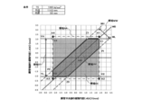
図8にて、鋼管端部に直接に雄ねじや雌ねじを切削装置にてねじ加工を行う場合について、説明する。鋼管中央部の縦楕円度ΔDCと鋼管端部の縦楕円度ΔDEの関係において、ねじ切削加工で、できる限り残肉を小さくし鋼管の軽量化を図りつつ、必要なねじ機能を確保するために確保すべき鋼管端部即ち切断後の鋼管端部の形状は、ΔDC、ΔDEが、以下に説明する領域AA、領域YYで共通に囲まれた領域(以下、領域XXと称する)を満足することである。
ここで図8において、領域AAとは、外径公差を確保するために必要な領域で、図8中の点A1、点A2、点A3、点A4で囲まれる領域で、鋼管中央部と鋼管端部で、JIS G 3444 (2016) 構造用鋼管で規定されている外径公差(1号公差) ±1%を満足する範囲である。尚、この外径公差は、規格に応じて変更して構わない。この範囲は、構造管として使用する際に、必要な円形の形状を確保するため必要な条件で、これを満足しない場合は、構造用鋼管として必要な曲げモーメントの確保、およびそこから得られる曲げ耐力、耐座屈性が保持できなくなる。この範囲は、構造管としての機能を確保させるために必要な範囲である。
図8において点A1~点A4は、下記(24)式~(31)式を満たす。
点A1:x(A1)=DCave×(2/100) (24)
y(A1)=DEave×(2/100) (25)
点A2:x(A2)=DCave×(2/100) (26)
y(A2)=DEave×(-2/100) (27)
点A3:x(A3)=DCave×(-2/100) (28)
y(A3)=DEave×(-2/100) (29)
点A4:x(A4)=DCave×(-2/100) (30)
y(A4)=DEave×(2/100) (31)
以上を整理すると、下記の(32)式、(33)式を同時に満たす(x、y)が領域AAである。
DCave×(-2/100)≦x≦DCave×(2/100) (32)
DEave×(-2/100)≦y≦DEave×(2/100) (33)
点A1:x(A1)=DCave×(2/100) (24)
y(A1)=DEave×(2/100) (25)
点A2:x(A2)=DCave×(2/100) (26)
y(A2)=DEave×(-2/100) (27)
点A3:x(A3)=DCave×(-2/100) (28)
y(A3)=DEave×(-2/100) (29)
点A4:x(A4)=DCave×(-2/100) (30)
y(A4)=DEave×(2/100) (31)
以上を整理すると、下記の(32)式、(33)式を同時に満たす(x、y)が領域AAである。
DCave×(-2/100)≦x≦DCave×(2/100) (32)
DEave×(-2/100)≦y≦DEave×(2/100) (33)
次に領域YYは、ねじ切削加工においてできる限り残肉を小さくし鋼管の軽量化を図りつつ、必要なねじ機能を確保するために確保すべき管端の形状の範囲である。発明者らは、高強度薄肉材のねじ加工を行う中で、管全体として継手の強度の確保するためには、図7に模式的に示した平均残肉について、下記(34)式、
平均残肉≧tEave/3 (34)
であることを見出した。残肉がこれ以下の場合は、管体として必要な継手強度が確保できず、使用時での継手部の破断など本来の用途としての機能を確保することができないと考えられる。
平均残肉≧tEave/3 (34)
であることを見出した。残肉がこれ以下の場合は、管体として必要な継手強度が確保できず、使用時での継手部の破断など本来の用途としての機能を確保することができないと考えられる。
一方、図7にあるように、鋼管の実際の外径が平均外径から部分的にずれた場合を考えると、発明者らは高強度薄肉材のねじ加工を行う中で、局部的なねじ部の変形防止の点から残肉限界は、下記(35)式、
限界残肉≧0.65mm (35)
であることを見出した。この値以下となった場合は、加工時にねじ部の変形による不良品の発生による製造コストの上昇、製品使用時でのねじ部の変形による使用不能になるなど製造上、使用上で問題が生じる場合がある。
限界残肉≧0.65mm (35)
であることを見出した。この値以下となった場合は、加工時にねじ部の変形による不良品の発生による製造コストの上昇、製品使用時でのねじ部の変形による使用不能になるなど製造上、使用上で問題が生じる場合がある。
ねじ切削加工においてできる限り残肉を小さくし鋼管の軽量化を図りつつ、必要なねじ機能を確保するために確保すべき管端の形状に必要な条件を求めると、図7の例にあるように縦長の場合は、雄ねじ側は、下記(36)式、
限界残肉=平均残肉-(dE1-dEave)/2≧0.65 (36)
で、電縫鋼管では帯鋼を素材として使用するので肉厚は平均肉厚で一定とすると、下記(37)式、(38)式、
dE1=DE1-2×tEave (37)
dEave=DEave-2×tEave (38)
である。(34)式、(35)式、(37)式および(38)式より、(36)式を変形すると、下記(39)式、
DE1-DEave≦2×{(tEave/3)-0.65} (39)
となる。雌ねじ側も同じく下記(40)式、
限界残肉=平均残肉-(DEave-DE3)/2≧0.65 (40)
であり、(34)式より、式を変形すると(40)式は、下記(41)式となり、
DEave-DE3≦2×{(tEave/3)-0.65} (41)
(39)式と(41)式の両辺を足すと、下記(42)式、
ΔDE=DE1-DE3≦4×{(tEave/3)-0.65} (42)
となる。
限界残肉=平均残肉-(dE1-dEave)/2≧0.65 (36)
で、電縫鋼管では帯鋼を素材として使用するので肉厚は平均肉厚で一定とすると、下記(37)式、(38)式、
dE1=DE1-2×tEave (37)
dEave=DEave-2×tEave (38)
である。(34)式、(35)式、(37)式および(38)式より、(36)式を変形すると、下記(39)式、
DE1-DEave≦2×{(tEave/3)-0.65} (39)
となる。雌ねじ側も同じく下記(40)式、
限界残肉=平均残肉-(DEave-DE3)/2≧0.65 (40)
であり、(34)式より、式を変形すると(40)式は、下記(41)式となり、
DEave-DE3≦2×{(tEave/3)-0.65} (41)
(39)式と(41)式の両辺を足すと、下記(42)式、
ΔDE=DE1-DE3≦4×{(tEave/3)-0.65} (42)
となる。
次に横長の場合、即ち図7で縦横を逆にした場合も、同じように、雄ねじ側は、下記(43)式、
DEave-DE1≦2×{(tEave/3)-0.65} (43)
雌ねじ側は、下記(44)式、
DE3-DEave≦2×{(tEave/3)-0.65} (44)
となり、(43)式と(44)式の両辺を足すと、下記(45)式、
DE3-DE1≦4×{(tEave/3)-0.65} (45)
(45)式を書き換えると、下記(46)式、
ΔDE=DE1-DE3≧-4×{(tEave/3)-0.65} (46)
となる。
DEave-DE1≦2×{(tEave/3)-0.65} (43)
雌ねじ側は、下記(44)式、
DE3-DEave≦2×{(tEave/3)-0.65} (44)
となり、(43)式と(44)式の両辺を足すと、下記(45)式、
DE3-DE1≦4×{(tEave/3)-0.65} (45)
(45)式を書き換えると、下記(46)式、
ΔDE=DE1-DE3≧-4×{(tEave/3)-0.65} (46)
となる。
以下、x軸は鋼管中央部の縦楕円度ΔDC、y軸は鋼管端部の縦楕円度ΔDEである図8~図13において、図中の点iのx軸成分をx(i)、y軸成分をy(i)と表現する。
また以下で説明する式の表記の中で、MAX(n、m)は、n、mのうち大きい方の値を示し、MIN(n、m)は、n、mのうち小さい方の値を示す。尚、図8~図9および図12~13は、TS=1000N/mm2、サイズが外径114.3mmで肉厚が3.5mmの条件におけるものである。図10及び図11は、TS=1000N/mm2、サイズが外径114.3mmで肉厚が4.0mmの条件におけるものである。
また以下で説明する式の表記の中で、MAX(n、m)は、n、mのうち大きい方の値を示し、MIN(n、m)は、n、mのうち小さい方の値を示す。尚、図8~図9および図12~13は、TS=1000N/mm2、サイズが外径114.3mmで肉厚が3.5mmの条件におけるものである。図10及び図11は、TS=1000N/mm2、サイズが外径114.3mmで肉厚が4.0mmの条件におけるものである。
図8において、前述の領域YY線の範囲を決定する線YH、線YLは、下記(47)式、(48)式、
線YH:y=4×{(tEave/3)-0.65} (47)
線YL:y=-4×{(tEave/3)-0.65} (48)
とすると、領域YYは(47)式と(48)式を同時に満たす領域で、図8では線YHと線YLで囲まれた部分である。尚、YH,YLは、ねじ切削加工においてできる限り残肉を小さくし鋼管の軽量化を図りつつ、必要なねじ機能を確保するために必要なΔDEの範囲の上限と下限である。式で表すと、下記の(49)式、(50)式を同時に満たす(x、y)が領域YYである。
-∞≦x≦∞ (49)
-4×{(tEave/3)-0.65}≦y≦4×{(tEave/3)-0.65} (50)
線YH:y=4×{(tEave/3)-0.65} (47)
線YL:y=-4×{(tEave/3)-0.65} (48)
とすると、領域YYは(47)式と(48)式を同時に満たす領域で、図8では線YHと線YLで囲まれた部分である。尚、YH,YLは、ねじ切削加工においてできる限り残肉を小さくし鋼管の軽量化を図りつつ、必要なねじ機能を確保するために必要なΔDEの範囲の上限と下限である。式で表すと、下記の(49)式、(50)式を同時に満たす(x、y)が領域YYである。
-∞≦x≦∞ (49)
-4×{(tEave/3)-0.65}≦y≦4×{(tEave/3)-0.65} (50)
領域AA、領域YYで共通に囲まれた領域XX、即ち構造管としての機能を確保させるための外径公差を確保し、できる限り残肉を小さくし鋼管の軽量化を図りつつ、必要なねじ機能を確保ができる領域は、点X1、点X2、点X3、点X4で囲まれた領域で、下記(51)式~(58)式で表される。
点X1:x(X1)=DCave×(2/100) (51)
y(X1)=YM (52)
点X2:x(X2)=DCave×(2/100) (53)
y(X2)=YN (54)
点X3:x(X3)=DCave×(-2/100) (55)
y(X3)=YN (56)
点X4:x(X4)=DCave×(-2/100) (57)
y(X4)=YM (58)
ここでYN、YMは図8には図示されていないが、以下とする。YNは、領域XXの範囲を規定する際、y成分の下限の範囲として領域AAのy成分 y=DEave×(-2/100) と領域YYのy成分 y=-4×(tEave/3)-0.65 の大きい方の値である。YMは、領域XXの範囲を規定する際、y成分の上限の範囲として領域AAのy成分 y=DEave×(2/100) と領域YYのy成分 y=4×(tEave/3)-0.65 の小さい方の値であり、(4)式、(5)式である。
YN=MAX[{DEave×(-2/100)}、{-4×((tEave/3)-0.65)}] (5)
YM=MIN[{DEave×( 2/100)}、{4×((tEave/3)-0.65)}] (4)
以上を整理すると、下記の(59)式、(60)式を同時に満たす(x、y)が領域XXである。
DCave×(-2/100)≦x≦DCave×(2/100) (59)
YN≦y≦YM (60)
点X1:x(X1)=DCave×(2/100) (51)
y(X1)=YM (52)
点X2:x(X2)=DCave×(2/100) (53)
y(X2)=YN (54)
点X3:x(X3)=DCave×(-2/100) (55)
y(X3)=YN (56)
点X4:x(X4)=DCave×(-2/100) (57)
y(X4)=YM (58)
ここでYN、YMは図8には図示されていないが、以下とする。YNは、領域XXの範囲を規定する際、y成分の下限の範囲として領域AAのy成分 y=DEave×(-2/100) と領域YYのy成分 y=-4×(tEave/3)-0.65 の大きい方の値である。YMは、領域XXの範囲を規定する際、y成分の上限の範囲として領域AAのy成分 y=DEave×(2/100) と領域YYのy成分 y=4×(tEave/3)-0.65 の小さい方の値であり、(4)式、(5)式である。
YN=MAX[{DEave×(-2/100)}、{-4×((tEave/3)-0.65)}] (5)
YM=MIN[{DEave×( 2/100)}、{4×((tEave/3)-0.65)}] (4)
以上を整理すると、下記の(59)式、(60)式を同時に満たす(x、y)が領域XXである。
DCave×(-2/100)≦x≦DCave×(2/100) (59)
YN≦y≦YM (60)
ここで発明者らは、前述したように鋼管中央部と鋼管端部の縦楕円度との関係を明確化し、これを用いて、造管において鋼管中央部の縦楕円度を一定の範囲に制御させることで、鋼管切断後の鋼管端部の縦楕円度を低位に確保してねじ切り可能とする方法を見出した。以下にその方法とその方法で得られる製品の領域を図8の領域PPとして示す。領域PPは、前述した領域XXと以下の後述する領域WWの重なった領域である。
領域WWとは、前述した鋼管中央部と鋼管端部の縦楕円度との関係を用い製造したときに得られる ΔDCとΔDEについて、ばらつきも含めてその範囲を示したものである。図8おける領域WWについて説明する。鋼管端部と鋼管中央部の縦楕円度には(61)式の関係があり、図8では、線WBで示される。
y=x+K (61)
ここで、yはΔDE、xはΔDCであり、これに置き換えると前述の(21)式となる。尚、Kは前述の(6)式で求められる定数である。
y=x+K (61)
ここで、yはΔDE、xはΔDCであり、これに置き換えると前述の(21)式となる。尚、Kは前述の(6)式で求められる定数である。
図8にあるように、この式より、ΔDE=0にするために、製造時に狙うべき鋼管中央部の縦楕円度x(=ΔDC)は、(62)式、
x(=ΔDC)=-K (62)
であり、図8においては点AIMであり、(61)式を満足させるべく造管時の成形、定形を行えば、容易に管端の縦楕円度を低くすることが可能となる。
x(=ΔDC)=-K (62)
であり、図8においては点AIMであり、(61)式を満足させるべく造管時の成形、定形を行えば、容易に管端の縦楕円度を低くすることが可能となる。
(61)式の関係を用いて製造した製品のΔDC、ΔDE範囲は、前述の(8)式で得られた鋼管中央部の平均外径DCaveの標準偏差を用い、ばらつきを考慮すると下記の線WH、線WLで囲まれた領域WWとなる。ここでWHは、平均から+3σであるΔDEの上限、WLは、平均から-3σであるΔDEの下限を示し、下記(63)式、(64)式となる。
線WH:y=x+K+3×SD (63)
線WL:y=x+K-3×SD (64)
ここでSDは縦楕円度の標準偏差で、ΔD=D1-D3であるので標準偏差の加法性より下記(7)式、
SD=(√2)×(鋼管中央部の平均外径DCaveの標準偏差) (7)
で表すことができる。鋼管中央部の平均外径DCaveの標準偏差は前述の(8)式で求められる数字である。式で表すと、下記の(3)式を同時に満たす(x、y)が領域WWである。
x+K-3×SD≦y≦x+K+3×SD (3)
線WH:y=x+K+3×SD (63)
線WL:y=x+K-3×SD (64)
ここでSDは縦楕円度の標準偏差で、ΔD=D1-D3であるので標準偏差の加法性より下記(7)式、
SD=(√2)×(鋼管中央部の平均外径DCaveの標準偏差) (7)
で表すことができる。鋼管中央部の平均外径DCaveの標準偏差は前述の(8)式で求められる数字である。式で表すと、下記の(3)式を同時に満たす(x、y)が領域WWである。
x+K-3×SD≦y≦x+K+3×SD (3)
(61)式の関係を用いて鋼管切断後の鋼管端部の縦楕円度を低位に確保する製造において、図8の領域PPは、できる限り残肉を小さくし鋼管の軽量化を図ることが可能な製品の範囲であり、領域XXと領域WWの重なった部分である。式で表すと、前述した下記の(59)式、(60)式および(3)式を同時に満たす(x、y)が領域PPである。
DCave×(-2/100)≦x≦DCave×(2/100) (59)
YN≦y≦YM (60)
x+K-3×SD≦y≦x+K+3×SD (3)
これを図8で座標で示すと、点X1、点P1、点Z3、点X3、点P2、点Z1、点X1を結んだ線の内側の領域である。点P1:X1とX2を通る線と線WLの交点である。点P2:X4とX3を通る線と線WHの交点である。点Z1:X4とX1を通る線と線WHの交点である。点Z3:X3とX2を通る線と線WLの交点である。
DCave×(-2/100)≦x≦DCave×(2/100) (59)
YN≦y≦YM (60)
x+K-3×SD≦y≦x+K+3×SD (3)
これを図8で座標で示すと、点X1、点P1、点Z3、点X3、点P2、点Z1、点X1を結んだ線の内側の領域である。点P1:X1とX2を通る線と線WLの交点である。点P2:X4とX3を通る線と線WHの交点である。点Z1:X4とX1を通る線と線WHの交点である。点Z3:X3とX2を通る線と線WLの交点である。
前述の(59)式のxの範囲で、同じく前述の(61)式の関係を用いて製造した場合、製造のばらつきが原因で、領域XXを満足できない場合が生じる。そこで、ねじ切削加工において、製造のばらつきを考慮して、安定的に領域XXを確保することが可能となるより好ましい領域として、図9に設定すべきΔDCの範囲およびそのとき得られるΔDEを領域ZZとして示す。式で表すと、下記の(65)式と、前述の(3)式を同時に満たす(x、y)が領域ZZである。
YN-K+3×SD≦x≦YM-K-3×SD (65)
x+K-3×SD≦y≦x+K+3×SD (3)
これを図9に座標で示すと、領域ZZは、領域XXを満たしかつ下記の4点、点Z1、点Z2、点Z3、点Z4を結んだ線に囲まれた領域である。
点Z1:X4とX1を通る線と線WHの交点であり、下記(66)式、(67)式で表される。
x(Z1)=y(X1)-K-3×SD=YM-K-3×SD (66)
y(Z1)=y(X1)=YM (67)
点Z2:x=x(Z1)と線WLの交点であり、下記(68)式、(69)式で表される。
x(Z2)=x(Z1)=y(X1)-K-3×SD
=YM-K-3×SD (68)
y(Z2)=x(Z1)+K-3×SD=YM-6×SD (69)
点Z3:X3とX2を通る線と線WLの交点であり、下記(70)式、(71)式で表される。
x(Z3)=y(X3)-K+3×SD=YN-K+3×SD (70)
y(Z3)=y(X3)=YN (71)
点Z4:x=x(Z3)と線WHの交点であり、下記(72)式、(73)式で表される。
x(Z4)=x(Z3)=y(X3)-K+3×SD
=YN-K+3×SD (72)
y(Z4)=x(Z3)+K+3×SD=YN+6×SD (73)
YN-K+3×SD≦x≦YM-K-3×SD (65)
x+K-3×SD≦y≦x+K+3×SD (3)
これを図9に座標で示すと、領域ZZは、領域XXを満たしかつ下記の4点、点Z1、点Z2、点Z3、点Z4を結んだ線に囲まれた領域である。
点Z1:X4とX1を通る線と線WHの交点であり、下記(66)式、(67)式で表される。
x(Z1)=y(X1)-K-3×SD=YM-K-3×SD (66)
y(Z1)=y(X1)=YM (67)
点Z2:x=x(Z1)と線WLの交点であり、下記(68)式、(69)式で表される。
x(Z2)=x(Z1)=y(X1)-K-3×SD
=YM-K-3×SD (68)
y(Z2)=x(Z1)+K-3×SD=YM-6×SD (69)
点Z3:X3とX2を通る線と線WLの交点であり、下記(70)式、(71)式で表される。
x(Z3)=y(X3)-K+3×SD=YN-K+3×SD (70)
y(Z3)=y(X3)=YN (71)
点Z4:x=x(Z3)と線WHの交点であり、下記(72)式、(73)式で表される。
x(Z4)=x(Z3)=y(X3)-K+3×SD
=YN-K+3×SD (72)
y(Z4)=x(Z3)+K+3×SD=YN+6×SD (73)
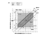
次に、鋼管の肉厚が厚くなると、領域YY(ねじ切削加工においてできる限り残肉を小さくし鋼管の軽量化を図りつつ、必要なねじ機能を確保するために必要な領域)が、領域AA(外径公差を確保するために必要な範囲)より大きくなる場合があり、その場合の領域PPを図10に示す。
この場合は、領域AAと領域YYの重なりである領域XXは、領域AAと同じになる。式で表すと、前述の下記の(32)式、(33)式を同時に満たす(x、y)が領域XXであり、下記(32)式、(33)式で表される。
DCave×(-2/100)≦x≦DCave×(2/100) (32)
DEave×(-2/100)≦y≦DEave×(2/100) (33)
これを図10で座標で示すと、領域XXは、下記の4点の点X1、点X2、点X3、点X4を結んだ線の内側の領域であり、下記(24)式~(31)式で表される。
点X1(=点A1):x(X1)=x(A1)=DCave×(2/100) (24)
y(X1)=y(A1)=DEave×(2/100) (25)
点X2(=点A2):x(X2)=x(A2)=DCave×(2/100) (26)
y(X2)=y(A2)=DEave×(-2/100) (27)
点X3(=点A3):x(X3)=x(A3)=DCave×(-2/100) (28)y(X3)=y(A3)=DEave×(-2/100) (29)
点X4(=点A4):x(X4)=x(A4)DCave×(-2/100) (30)y(X4)=y(A4)=DEave×(2/100) (31)
DCave×(-2/100)≦x≦DCave×(2/100) (32)
DEave×(-2/100)≦y≦DEave×(2/100) (33)
これを図10で座標で示すと、領域XXは、下記の4点の点X1、点X2、点X3、点X4を結んだ線の内側の領域であり、下記(24)式~(31)式で表される。
点X1(=点A1):x(X1)=x(A1)=DCave×(2/100) (24)
y(X1)=y(A1)=DEave×(2/100) (25)
点X2(=点A2):x(X2)=x(A2)=DCave×(2/100) (26)
y(X2)=y(A2)=DEave×(-2/100) (27)
点X3(=点A3):x(X3)=x(A3)=DCave×(-2/100) (28)y(X3)=y(A3)=DEave×(-2/100) (29)
点X4(=点A4):x(X4)=x(A4)DCave×(-2/100) (30)y(X4)=y(A4)=DEave×(2/100) (31)
図10において、前述の鋼管中央部と鋼管端部の縦楕円度との関係を用い製造したときに得られるΔDCとΔDEについて、ばらつきも含めてその範囲を示した領域WWは前述の説明と同じであり、前述の下記(3)式を同時に満たす(x、y)が領域WWであり、下記(3)式で表される。
x+K-3×SD≦y≦x+K+3×SD (3)
x+K-3×SD≦y≦x+K+3×SD (3)
図10において、領域PPは、領域XXと領域WWの重なった部分である。式で表すと、下記の(32)式、(33)式および(3)式を同時に満たす(x、y)が領域PPである。
DCave×(-2/100)≦x≦DCave×(2/100) (32)
DEave×(-2/100)≦y≦DEave×(2/100) (33)
x+K-3×SD≦y≦x+K+3×SD (3)
これを図10において座標で示すと、点X1、点P1、点Z3、点X3、点P2、点Z1、点X1を結んだ線の内側の領域である。ここで、
点P1:X1とX2を通る線と線WLの交点である。
点P2:X4とX3を通る線と線WHの交点である。
点Z1:X4とX1を通る線と線WHの交点である。
点Z3:X3とX2を通る線と線WLの交点である。
DCave×(-2/100)≦x≦DCave×(2/100) (32)
DEave×(-2/100)≦y≦DEave×(2/100) (33)
x+K-3×SD≦y≦x+K+3×SD (3)
これを図10において座標で示すと、点X1、点P1、点Z3、点X3、点P2、点Z1、点X1を結んだ線の内側の領域である。ここで、
点P1:X1とX2を通る線と線WLの交点である。
点P2:X4とX3を通る線と線WHの交点である。
点Z1:X4とX1を通る線と線WHの交点である。
点Z3:X3とX2を通る線と線WLの交点である。
この場合の製造のばらつきを考慮して、安定的に領域XXを確保することが可能となるより好ましい領域である領域ZZを図11に示す。考え方は、前述と同じであるが、領域XXのy成分が異なり、
y(X1)=y(X4)=DEave×(2/100) (25)および(31)
y(X2)=y(X3)=DEave×(-2/100) (27)および(29)
となるため、式で表すと、下記の(74)式、(3)式を同時に満たす(x、y)が領域ZZである。
DEave×(-2/100)-K+3×SD≦x
≦DEave×(2/100)-K-3×SD (74)
x+K-3×SD≦y≦x+K+3×SD (3)
これを図11において座標で示すと、領域ZZは、領域XXを満たし、かつ下記の4点の点Z1、点Z2、点Z3、点Z4を結んだ線の内側の領域であり、下記(75)式~(82)式で表される。
点Z1:X4とX1を通る線と線WHの交点である。
x(Z1)=y(X1)-K-3×SD
=DEave×(2/100)-K-3×SD (75)
y(Z1)=y(X1)=DEave×(2/100) (76)
点Z2:x=x(Z1)と線WLの交点である。
x(Z2)=x(Z1)=y(X1)-K-3×SD
=DEave×(2/100)-K-3×SD (77)
y(Z2)=x(Z1)+K-3×SD
=DEave×(2/100)-6×SD (78)
点Z3:X3とX2を通る線と線WLの交点である。
x(Z3)=y(X3)-K+3×SD
=DEave×(-2/100)-K+3×SD (79)
y(Z3)=y(X3)=DEave×(-2/100) (80)
点Z4:x=x(Z3)と線WHの交点である。
x(Z4)=x(Z3)=y(X3)-K+3×SD
=DEave×(-2/100)-K+3×SD (81)
y(Z4)=x(Z3)+K+3×SD
=DEave×(-2/100)+6×SD (82)
y(X1)=y(X4)=DEave×(2/100) (25)および(31)
y(X2)=y(X3)=DEave×(-2/100) (27)および(29)
となるため、式で表すと、下記の(74)式、(3)式を同時に満たす(x、y)が領域ZZである。
DEave×(-2/100)-K+3×SD≦x
≦DEave×(2/100)-K-3×SD (74)
x+K-3×SD≦y≦x+K+3×SD (3)
これを図11において座標で示すと、領域ZZは、領域XXを満たし、かつ下記の4点の点Z1、点Z2、点Z3、点Z4を結んだ線の内側の領域であり、下記(75)式~(82)式で表される。
点Z1:X4とX1を通る線と線WHの交点である。
x(Z1)=y(X1)-K-3×SD
=DEave×(2/100)-K-3×SD (75)
y(Z1)=y(X1)=DEave×(2/100) (76)
点Z2:x=x(Z1)と線WLの交点である。
x(Z2)=x(Z1)=y(X1)-K-3×SD
=DEave×(2/100)-K-3×SD (77)
y(Z2)=x(Z1)+K-3×SD
=DEave×(2/100)-6×SD (78)
点Z3:X3とX2を通る線と線WLの交点である。
x(Z3)=y(X3)-K+3×SD
=DEave×(-2/100)-K+3×SD (79)
y(Z3)=y(X3)=DEave×(-2/100) (80)
点Z4:x=x(Z3)と線WHの交点である。
x(Z4)=x(Z3)=y(X3)-K+3×SD
=DEave×(-2/100)-K+3×SD (81)
y(Z4)=x(Z3)+K+3×SD
=DEave×(-2/100)+6×SD (82)
次に、鋼管と鋼管の間に1ないし複数の治具を介して鋼管端部に嵌合して連結して使用する場合について説明する。この場合の、鋼造管としての機能を確保させるための外径公差を確保したうえで、前述の鋼管端部の縦楕円度(ΔDE)と鋼管中央部の縦楕円度(ΔDC)の差の関係を用いて、造管において鋼管中央部の縦楕円度を一定の範囲に制御し鋼管切断後の鋼管端部の縦楕円度を低位に確保する方法で得られる製品の領域を図12に領域PPとして、より好ましい領域を図13に領域ZZとして示す。尚、鋼管と鋼管の間に1ないし複数の治具を介して鋼管端部に嵌合して連結して使用する場合については、領域YYは考える必要がない。
ねじ切削加工と同じように、嵌合させるに付き確保すべき管端の形状の範囲を領域XXとすると、領域XXは領域AAと同じであり、式で表すと、下記の(32)式、(33)式を同時に満たす(x、y)が領域XX(=領域AA)である。
DCave×(-2/100)≦x≦DCave×(2/100) (32)
DEave×(-2/100)≦y≦DEave×(2/100) (33)
これを図12において座標で示すと、以下の点X1、点X2、点X3、点X4を結んだ線の内側の領域であり、下記(24)式から(31)式で表される。
点X1:x(X1)=DCave×(2/100) (24)
y(X1)=DEave×(2/100) (25)
点X2:x(X2)=DCave×(2/100) (26)
y(X2)=DEave×(-2/100) (27)
点X3:x(X3)=DCave×(-2/100) (28)
y(X3)=DEave×(-2/100) (29)
点X4:x(X4)=DCave×(-2/100) (30)
y(X4)=DEave×(2/100) (31)
DCave×(-2/100)≦x≦DCave×(2/100) (32)
DEave×(-2/100)≦y≦DEave×(2/100) (33)
これを図12において座標で示すと、以下の点X1、点X2、点X3、点X4を結んだ線の内側の領域であり、下記(24)式から(31)式で表される。
点X1:x(X1)=DCave×(2/100) (24)
y(X1)=DEave×(2/100) (25)
点X2:x(X2)=DCave×(2/100) (26)
y(X2)=DEave×(-2/100) (27)
点X3:x(X3)=DCave×(-2/100) (28)
y(X3)=DEave×(-2/100) (29)
点X4:x(X4)=DCave×(-2/100) (30)
y(X4)=DEave×(2/100) (31)
鋼管と鋼管の間に1ないし複数の治具を介して鋼管端部に嵌合して連結して使用する場合で、前述の鋼管中央部と鋼管端部の縦楕円度との関係を用い製造したときに得られるΔDCとΔDEについて、ばらつきも含めてその範囲を示した図12,図13の領域WWは前述の説明と同じであり、下記の(3)式を同時に満たす(x、y)が領域WWである。
x+K-3×SD≦y≦x+K+3×SD (3)
x+K-3×SD≦y≦x+K+3×SD (3)
図12において、前述の鋼管中央部と鋼管端部の縦楕円度との関係を用いて、造管において鋼管中央部の縦楕円度を一定の範囲に制御し鋼管切断後の鋼管端部の縦楕円度を低位に確保する方法で得られる製品の領域である領域PPは、領域XXと領域WWの重なった部分である。式で表すと、下記の(32)式、(33)式および(3)式を同時に満たす(x、y)が領域PPである。
DCave×(-2/100)≦x≦DCave×(2/100) (32)
DEave×(-2/100)≦y≦DEave×(2/100) (33)
x+K-3×SD≦y≦x+K+3×SD (3)
これを図12において座標で示すと、点X1、点P1、点Z3、点X3、点P2、点Z1、点X1を結んだ線の内側の領域である。ここで、
点P1:X1とX2を通る線と線WLの交点である。
点P2:X4とX3を通る線と線WHの交点である。
点Z1:X4とX1を通る線と線WHの交点である。
点Z3:X3とX2を通る線と線WLの交点である。
DCave×(-2/100)≦x≦DCave×(2/100) (32)
DEave×(-2/100)≦y≦DEave×(2/100) (33)
x+K-3×SD≦y≦x+K+3×SD (3)
これを図12において座標で示すと、点X1、点P1、点Z3、点X3、点P2、点Z1、点X1を結んだ線の内側の領域である。ここで、
点P1:X1とX2を通る線と線WLの交点である。
点P2:X4とX3を通る線と線WHの交点である。
点Z1:X4とX1を通る線と線WHの交点である。
点Z3:X3とX2を通る線と線WLの交点である。
次に図13に、鋼管と鋼管の間に1ないし複数の治具を介して鋼管端部に嵌合して連結して使用する場合について、製造のばらつきを考慮して、安定的に領域XXを確保することが可能となるより好ましい領域ZZを示す。考え方は、前述と同じであるが、領域XXのy成分が異なり、
y(X1)=y(X4)=DEave×(2/100) (25)および(31)
y(X2)=y(X3)=DEave×(-2/100) (27)および(29)
となるため、式で表すと、下記の(74)式、(3)式を同時に満たす(x、y)が領域ZZである。
DEave×(-2/100)-K+3×SD≦x
≦DEave×(2/100)-K-3×SD (74)
x+K-3×SD≦y≦x+K+3×SD (3)
図13において座標で示すと、領域ZZは、領域XXを満たしかつ下記の4点、点Z1、点Z2、点Z3、点Z4を結んだ線に囲まれた領域であり、下記(75)式~(82)式で表される。
点Z1:X4とX1を通る線と線WHの交点である。
x(Z1)=y(X1)-K-3×SD
=DEave×(2/100)-K-3×SD (75)
y(Z1)=y(X1)=DEave×(2/100) (76)
点Z2:x=x(Z1)と線WLの交点である。
x(Z2)=x(Z1)=y(X1)-K-3×SD
=DEave×(2/100)-K-3×SD (77)
y(Z2)=x(Z1)+K-3×SD
=DEave×(2/100)-6×SD (78)
点Z3:X3とX2を通る線と線WLの交点である。
x(Z3)=y(X3)-K+3×SD
=DEave×(-2/100)-K+3×SD (79)
y(Z3)=y(X3)=DEave×(-2/100) (80)
点Z4:x=x(Z3)と線WHの交点である。
x(Z4)=x(Z3)=y(X3)-K+3×SD
=DEave×(-2/100)-K+3×SD (81)
y(Z4)=x(Z3)+K+3×SD
=DEave×(-2/100)+6×SD (82)
y(X1)=y(X4)=DEave×(2/100) (25)および(31)
y(X2)=y(X3)=DEave×(-2/100) (27)および(29)
となるため、式で表すと、下記の(74)式、(3)式を同時に満たす(x、y)が領域ZZである。
DEave×(-2/100)-K+3×SD≦x
≦DEave×(2/100)-K-3×SD (74)
x+K-3×SD≦y≦x+K+3×SD (3)
図13において座標で示すと、領域ZZは、領域XXを満たしかつ下記の4点、点Z1、点Z2、点Z3、点Z4を結んだ線に囲まれた領域であり、下記(75)式~(82)式で表される。
点Z1:X4とX1を通る線と線WHの交点である。
x(Z1)=y(X1)-K-3×SD
=DEave×(2/100)-K-3×SD (75)
y(Z1)=y(X1)=DEave×(2/100) (76)
点Z2:x=x(Z1)と線WLの交点である。
x(Z2)=x(Z1)=y(X1)-K-3×SD
=DEave×(2/100)-K-3×SD (77)
y(Z2)=x(Z1)+K-3×SD
=DEave×(2/100)-6×SD (78)
点Z3:X3とX2を通る線と線WLの交点である。
x(Z3)=y(X3)-K+3×SD
=DEave×(-2/100)-K+3×SD (79)
y(Z3)=y(X3)=DEave×(-2/100) (80)
点Z4:x=x(Z3)と線WHの交点である。
x(Z4)=x(Z3)=y(X3)-K+3×SD
=DEave×(-2/100)-K+3×SD (81)
y(Z4)=x(Z3)+K+3×SD
=DEave×(-2/100)+6×SD (82)
次に、本実施形態の高強度電縫鋼管の製造方法について説明する。
高強度電縫鋼管に使用される熱延鋼板は、前述した成分を有する鋼を加熱して熱間圧延後、制御冷却を行い、巻き取ることで製造される。
鋼の加熱温度は、Nbなど、炭化物を形成する元素を鋼中に固溶させるために、1150℃以上が好ましい。一方、細粒組織を得るためには、1000℃~1280℃が好ましい。加熱温度が高すぎるとオーステナイト粒が粗大になり、結果としてフェライトの粒径が粗大化になるので、1280℃以下が好ましい。
熱間圧延の仕上温度は、圧延中にフェライトが生成しないようにするため、850℃以上が好ましい。
巻取温度は、300℃超とすると、充分な強度が確保できないおそれがあるため、300℃以下が好ましい。さらに好ましくは、150℃以下である。
次に、得られた熱延鋼板をロール成形により連続的にオープン管に成形し、次いでオープン管の端部同士を突き合わせで電縫溶接し、電縫溶接鋼管を製造する。電縫溶接部を加熱し、加速冷却するシーム熱処理を施してもよい。その後、サイザーで鋼管の外径を0.5%~4.0%の縮径加工を施してもよい。
高強度電縫鋼管に使用される熱延鋼板は、前述した成分を有する鋼を加熱して熱間圧延後、制御冷却を行い、巻き取ることで製造される。
鋼の加熱温度は、Nbなど、炭化物を形成する元素を鋼中に固溶させるために、1150℃以上が好ましい。一方、細粒組織を得るためには、1000℃~1280℃が好ましい。加熱温度が高すぎるとオーステナイト粒が粗大になり、結果としてフェライトの粒径が粗大化になるので、1280℃以下が好ましい。
熱間圧延の仕上温度は、圧延中にフェライトが生成しないようにするため、850℃以上が好ましい。
巻取温度は、300℃超とすると、充分な強度が確保できないおそれがあるため、300℃以下が好ましい。さらに好ましくは、150℃以下である。
次に、得られた熱延鋼板をロール成形により連続的にオープン管に成形し、次いでオープン管の端部同士を突き合わせで電縫溶接し、電縫溶接鋼管を製造する。電縫溶接部を加熱し、加速冷却するシーム熱処理を施してもよい。その後、サイザーで鋼管の外径を0.5%~4.0%の縮径加工を施してもよい。
電縫鋼管の製造工程の一例を図14に示す。電縫鋼管は複数のロールスタンドによる冷間加工により製造され、鋼板を曲げてC断面とする成形工程、管端を電縫する溶接工程、管を僅かに縮径して形状を調整する矯正工程と、切断機で鋼管を所望の長さで切断する切断工程から成る。A-A’断面は溶接工程のスタンド位置、B-B’断面は1つまたは複数ある矯正工程のいずれか1つのスタンド位置、C-C’断面は矯正工程の最終段のロールの中心位置と切断した鋼管端部の間で、切断した位置から位置Leより大きい位置の任意の位置の断面、D-D’断面は鋼管端部である。また各断面における管幅と管高さをそれぞれAh、Av、Bh、Bv、D1(鋼管中央部)、D3(鋼管中央部)、D1(鋼管端部)、D3(鋼管端部)(mm)とする。管幅とは90°~270°間の管外面距離、管高さとは電縫溶接部を0°位置とした場合の0°~180°間の管外面距離である。
ΔDCが適切な値となるように造り込むためには、溶接スタンドの上・下・幅ロールを適宜調整してA-A’断面の管幅Ahと管高さAvを適切な値とするか、矯正スタンド最終段の上・下・幅ロールを適宜調整してB-B’断面の管幅Bhと管高さBvを適切な値にすればよい。鋼管の靱性や耐食性を考慮して矯正時の冷間加工を最小限とする場合は、前者による造り込みが好ましい。また鋼管を加工硬化させて、さらなる高強度化を狙う場合は、後者による造り込みが好ましい。尚、電鋼鋼管の製造工程は図14の事例に限らず、ロールの個数、段数、形状が異なるので、それぞれの設備において本発明の条件を満足する造り込み条件を探索することとなる。
以上の説明の中で、鋼管と鋼管の間に1ないし複数の治具を介して鋼管端部に嵌合して連結して使用する方法においては、嵌合部は、溶接、接着もしくは機械的な接合(例えば、ねじ加工、材料の弾性を利用した嵌め合い、ピン止め等)などで鋼管と治具が強固に接合される場合も含むものとする。尚、「治具」とは、カップリングやニップルであって、鋼管に直接ねじを切削するのではなく、カップリングやニップルを鋼管に溶接や機械的接合により接合する。
また本発明に係る高強度電縫鋼管の長さは、前述のように2000mm~5000mmであることが好ましいが、一般的に使用されている長さである3000mm~3500mmであることがより好ましい。
次に、本実施形態に係る高強度電縫鋼管の組成について説明する。
以下において、各元素について、単に「含有量」というときは、鋼管中における含有量を指す。
以下において、各元素について、単に「含有量」というときは、鋼管中における含有量を指す。
本実施形態の鋼管は、前述の通り、質量%または質量ppmで、C:0.04~0.30%、Si:0.01~2.00%、Mn:0.50~3.00%、P:0.030%以下、S:0.030%以下、Al:0.005~0.700%、N:100ppm以下、Nb:0~0.100%、V:0~0.100%、Ti:0~0.200%、Ni:0~1.000%、Cu:0~1.000%、Cr:0~1.000%、Mo:0~1.000%、B:0~50ppm、Ca:0~100ppmおよびREM:0~200ppmを含有し、残部が鉄および不純物である。
以下、各元素および含有量、並びに不純物について説明する。
以下、各元素および含有量、並びに不純物について説明する。
<C:0.04~0.30%>
C(炭素)は、鋼管の強度の向上に有効な元素である。
本発明の鋼管におけるCの含有量は、0.04%以上である。これにより、熱延鋼板の、結果として鋼管の強度が確保される。
一方、Cの含有量が多すぎると、鋼管の強度が高くなりすぎ、靭性が劣化する。このため、Cの含有量の上限は0.30%である。Cの含有量の上限は、0.25%が好ましく、0.20%がより好ましい。
C(炭素)は、鋼管の強度の向上に有効な元素である。
本発明の鋼管におけるCの含有量は、0.04%以上である。これにより、熱延鋼板の、結果として鋼管の強度が確保される。
一方、Cの含有量が多すぎると、鋼管の強度が高くなりすぎ、靭性が劣化する。このため、Cの含有量の上限は0.30%である。Cの含有量の上限は、0.25%が好ましく、0.20%がより好ましい。
<Si:0.01~2.00%>
Si(ケイ素)は、脱酸剤として有効である。
しかし、Siの含有量が多すぎると、低温靭性が損なわれ、更に、電縫溶接性が損われる。このため、Siの含有量の上限は2.00%である。Siの含有量は、1.20%以下が好ましく、0.60%以下がより好ましい。
一方、脱酸剤としての効果がより効果的に得られる点から、Siの含有量は、0.01%以上である。さらに、固溶強化によって鋼管の強度がより高められる点で、Siの含有量は、0.10%以上が好ましく、0.20%以上がより好ましい。
Si(ケイ素)は、脱酸剤として有効である。
しかし、Siの含有量が多すぎると、低温靭性が損なわれ、更に、電縫溶接性が損われる。このため、Siの含有量の上限は2.00%である。Siの含有量は、1.20%以下が好ましく、0.60%以下がより好ましい。
一方、脱酸剤としての効果がより効果的に得られる点から、Siの含有量は、0.01%以上である。さらに、固溶強化によって鋼管の強度がより高められる点で、Siの含有量は、0.10%以上が好ましく、0.20%以上がより好ましい。
<Mn:0.50~3.00%>
Mn(マンガン)は、鋼の焼入れ性を高めることによって鋼を高強度化する元素である。
本発明の鋼管中におけるMn(マンガン)の含有量は、高い強度を確保する点から、0.50%以上である。Mnの含有量は、0.80%以上であることが好ましい。
しかし、Mnの含有量が多すぎると、マルテンサイトの生成が助長され、靱性が劣化する。このため、Mnの含有量の上限は3.00%である。より高い靭性を得るためには、上限は2.00%が好ましい。
Mn(マンガン)は、鋼の焼入れ性を高めることによって鋼を高強度化する元素である。
本発明の鋼管中におけるMn(マンガン)の含有量は、高い強度を確保する点から、0.50%以上である。Mnの含有量は、0.80%以上であることが好ましい。
しかし、Mnの含有量が多すぎると、マルテンサイトの生成が助長され、靱性が劣化する。このため、Mnの含有量の上限は3.00%である。より高い靭性を得るためには、上限は2.00%が好ましい。
<P:0.030%以下>
P(リン)は、不純物である。
Pの含有量の低減により、靭性が向上することから、Pの含有量の上限は0.030%である。Pの含有量は0.020%以下が好ましい。
Pの含有量は少ない方が好ましいため、Pの含有量の下限には特に制限はない。但し、特性とコストとのバランスの観点から、通常は、Pの含有量は0.001%以上である。
P(リン)は、不純物である。
Pの含有量の低減により、靭性が向上することから、Pの含有量の上限は0.030%である。Pの含有量は0.020%以下が好ましい。
Pの含有量は少ない方が好ましいため、Pの含有量の下限には特に制限はない。但し、特性とコストとのバランスの観点から、通常は、Pの含有量は0.001%以上である。
<S:0.030%以下>
S(硫黄)は、不純物である。
Sの含有量の低減により、熱間圧延によって延伸化するMnSを低減し、靭性を向上させることができることから、Sの含有量の上限は0.030%である。Sの含有量は、0.020%以下が好ましく、0.010%以下がより好ましい。
Sの含有量は少ない方が好ましいので、Sの含有量の下限には特に制限はない。但し、特性とコストとのバランスの観点から、通常は、Sの含有量は0.001%以上である。
S(硫黄)は、不純物である。
Sの含有量の低減により、熱間圧延によって延伸化するMnSを低減し、靭性を向上させることができることから、Sの含有量の上限は0.030%である。Sの含有量は、0.020%以下が好ましく、0.010%以下がより好ましい。
Sの含有量は少ない方が好ましいので、Sの含有量の下限には特に制限はない。但し、特性とコストとのバランスの観点から、通常は、Sの含有量は0.001%以上である。
<Al:0.005~0.700%>
Al(アルミニウム)は、脱酸剤として有効な元素である。
しかし、Alの含有量が多すぎると、介在物が増加して、延性や靭性が損なわれる。このため、Alの含有量の上限は0.700%である。
一方、脱酸剤としての効果をより効果的に得る点から、Alの含有量は0.005%以上である。介在物を低減して、より高い延性や靭性を得るためには、上限は0.100%以下が好ましい。
Al(アルミニウム)は、脱酸剤として有効な元素である。
しかし、Alの含有量が多すぎると、介在物が増加して、延性や靭性が損なわれる。このため、Alの含有量の上限は0.700%である。
一方、脱酸剤としての効果をより効果的に得る点から、Alの含有量は0.005%以上である。介在物を低減して、より高い延性や靭性を得るためには、上限は0.100%以下が好ましい。
<N:100ppm以下>
N(窒素)は、鋼中に不可避的に存在する元素である。
しかし、Nの含有量が多すぎると、AlN等の介在物が過度に増大して表面傷、靱性劣化等の弊害が生じるおそれがある。このため、Nの含有量の上限は100ppmである。Nの含有量は、80ppm以下が好ましく、60ppm以下が特に好ましい。
一方、Nの含有量の下限には特に制限はないが、脱N(脱窒)のコストや経済性を考慮すると、Nの含有量は、10ppm以上が好ましい。
N(窒素)は、鋼中に不可避的に存在する元素である。
しかし、Nの含有量が多すぎると、AlN等の介在物が過度に増大して表面傷、靱性劣化等の弊害が生じるおそれがある。このため、Nの含有量の上限は100ppmである。Nの含有量は、80ppm以下が好ましく、60ppm以下が特に好ましい。
一方、Nの含有量の下限には特に制限はないが、脱N(脱窒)のコストや経済性を考慮すると、Nの含有量は、10ppm以上が好ましい。
<Nb:0~0.100%>
Nb(ニオブ)は、再結晶温度を低下させる元素であり、熱間圧延を行う際に、オーステナイトの再結晶を抑制して組織の微細化に寄与する元素である。
しかし、Nbの含有量が多すぎると、粗大な析出物によって靭性が劣化する。このため、Nbの含有量の上限は0.100%である。Nbの含有量は、0.06%以下が好ましく、0.05%以下がより好ましい。
一方、組織微細化効果をより確実に得る点から、Nbの含有量は、0.010%以上が好ましく、0.020%以上が特に好ましい。
Nb(ニオブ)は、再結晶温度を低下させる元素であり、熱間圧延を行う際に、オーステナイトの再結晶を抑制して組織の微細化に寄与する元素である。
しかし、Nbの含有量が多すぎると、粗大な析出物によって靭性が劣化する。このため、Nbの含有量の上限は0.100%である。Nbの含有量は、0.06%以下が好ましく、0.05%以下がより好ましい。
一方、組織微細化効果をより確実に得る点から、Nbの含有量は、0.010%以上が好ましく、0.020%以上が特に好ましい。
<V:0~0.100%>
V(バナジウム)は、炭化物、窒化物を生成し、析出強化によって鋼の強度を向上させる元素である。
しかし、Vの含有量が多すぎると、炭化物及び窒化物が粗大化し、靭性の劣化をもたらすおそれがある。このため、Vの含有量は0~0.100%である。Vの含有量は0.060%以下がより好ましい。
一方、鋼管の強度をより向上させる点から、Vの含有量は0.010%以上が好ましい。
V(バナジウム)は、炭化物、窒化物を生成し、析出強化によって鋼の強度を向上させる元素である。
しかし、Vの含有量が多すぎると、炭化物及び窒化物が粗大化し、靭性の劣化をもたらすおそれがある。このため、Vの含有量は0~0.100%である。Vの含有量は0.060%以下がより好ましい。
一方、鋼管の強度をより向上させる点から、Vの含有量は0.010%以上が好ましい。
<Ti:0~0.200%>
Ti(チタン)は、微細な窒化物(TiN)を形成し、スラブ加熱時のオーステナイト粒の粗大化を抑制し組織の微細化に寄与する元素である。
しかし、Tiの含有量が多すぎると、TiNの粗大化や、TiCによる析出硬化が生じ、靭性が劣化するおそれがある。このため、Tiの含有量は、0~0.200%である。Tiの含有量は0.100%以下がより好ましく、0.050%以下が特に好ましい。
一方、組織の微細化により靱性をより向上させる観点からは、Tiの含有量は、0.010%以上が好ましく、0.015%以上がより好ましい。
Ti(チタン)は、微細な窒化物(TiN)を形成し、スラブ加熱時のオーステナイト粒の粗大化を抑制し組織の微細化に寄与する元素である。
しかし、Tiの含有量が多すぎると、TiNの粗大化や、TiCによる析出硬化が生じ、靭性が劣化するおそれがある。このため、Tiの含有量は、0~0.200%である。Tiの含有量は0.100%以下がより好ましく、0.050%以下が特に好ましい。
一方、組織の微細化により靱性をより向上させる観点からは、Tiの含有量は、0.010%以上が好ましく、0.015%以上がより好ましい。
<Ni:0~1.000%>
Ni(ニッケル)は、鋼の焼入れ性を高めることによって鋼を高強度化する元素である。また、Niは、靭性の向上に寄与する元素でもある。
しかし、Niは高価な元素であるため、経済性の点から、Niの含有量は0~1.000%である。Niの含有量は0.500%以下がより好ましい。
一方、靱性をより向上させる観点から、Niの含有量は0.100%以上であることが好ましい。
Ni(ニッケル)は、鋼の焼入れ性を高めることによって鋼を高強度化する元素である。また、Niは、靭性の向上に寄与する元素でもある。
しかし、Niは高価な元素であるため、経済性の点から、Niの含有量は0~1.000%である。Niの含有量は0.500%以下がより好ましい。
一方、靱性をより向上させる観点から、Niの含有量は0.100%以上であることが好ましい。
<Cu:0~1.000%>
Cu(銅)は、鋼の焼入れ性を高めることによって鋼を高強度化する元素である。また、Cuは、固溶強化に寄与する元素でもある。
しかし、Cuの含有量が多すぎると、鋼管の表面性状が損なわれる場合がある。このため、Cuの含有量は0~1.000%である。Cuの含有量は0.500%以下がより好ましい。
一方、Cuの含有量は、0.100%以上が好ましい。
なお、鋼管がCuを含有する場合は、表面性状劣化防止の観点から、同時にNiを含有することが好ましい。
Cu(銅)は、鋼の焼入れ性を高めることによって鋼を高強度化する元素である。また、Cuは、固溶強化に寄与する元素でもある。
しかし、Cuの含有量が多すぎると、鋼管の表面性状が損なわれる場合がある。このため、Cuの含有量は0~1.000%である。Cuの含有量は0.500%以下がより好ましい。
一方、Cuの含有量は、0.100%以上が好ましい。
なお、鋼管がCuを含有する場合は、表面性状劣化防止の観点から、同時にNiを含有することが好ましい。
<Cr:0~1.000%>
Cr(クロム)は、強度の向上に有効な元素である。
しかし、Crの含有量が多すぎると、電縫溶接性が劣化することがあるため、Crの含有量は、0~1.000%以下である。Crの含有量は0.500%以下がより好ましい。
一方、鋼管の強度をより向上させる点から、Crの含有量は0.100%以上が好ましい。
Cr(クロム)は、強度の向上に有効な元素である。
しかし、Crの含有量が多すぎると、電縫溶接性が劣化することがあるため、Crの含有量は、0~1.000%以下である。Crの含有量は0.500%以下がより好ましい。
一方、鋼管の強度をより向上させる点から、Crの含有量は0.100%以上が好ましい。
<Mo:0~1.000%>
Mo(モリブデン)は、鋼の高強度化に寄与する元素である。
しかし、Moは高価な元素であるため、経済性の点から、Moの含有量は0~1.000%である。Moの含有量は0.500%以下がより好ましく、0.300%以下が特に好ましい。
一方、Moの含有量は、0.050%以上が好ましい。
Mo(モリブデン)は、鋼の高強度化に寄与する元素である。
しかし、Moは高価な元素であるため、経済性の点から、Moの含有量は0~1.000%である。Moの含有量は0.500%以下がより好ましく、0.300%以下が特に好ましい。
一方、Moの含有量は、0.050%以上が好ましい。
<B:0~50ppm>
B(ホウ素)は、微量の含有により鋼の焼入れ性を顕著に高めて鋼の高強度化に寄与する元素である。
しかし、Bは、含有量50ppmを超えて含有させても焼入れ性の更なる向上は起きないのみならず、析出物を生成して靭性を劣化させる可能性があるので、Bの含有量の上限は50ppmである。一方、Bは原料不純物から混入することがあるが、焼入れ性の効果を十分得るためには、Bの含有量は、3ppm以上であることが好ましい。
B(ホウ素)は、微量の含有により鋼の焼入れ性を顕著に高めて鋼の高強度化に寄与する元素である。
しかし、Bは、含有量50ppmを超えて含有させても焼入れ性の更なる向上は起きないのみならず、析出物を生成して靭性を劣化させる可能性があるので、Bの含有量の上限は50ppmである。一方、Bは原料不純物から混入することがあるが、焼入れ性の効果を十分得るためには、Bの含有量は、3ppm以上であることが好ましい。
<Ca:0~100ppm>
Ca(カルシウム)は、硫化物系介在物の形態を制御し、低温靭性を向上させ、さらに、電縫溶接部の酸化物を微細化して電縫溶接部の靭性を向上させる元素である。
しかし、Caの含有量が多すぎると、酸化物又は硫化物が大きくなり靭性に悪影響を及ぼすおそれがある。このため、Caの含有量は、0~100ppmである。
一方、Caの含有量は、10ppm以上であることが好ましい。
Ca(カルシウム)は、硫化物系介在物の形態を制御し、低温靭性を向上させ、さらに、電縫溶接部の酸化物を微細化して電縫溶接部の靭性を向上させる元素である。
しかし、Caの含有量が多すぎると、酸化物又は硫化物が大きくなり靭性に悪影響を及ぼすおそれがある。このため、Caの含有量は、0~100ppmである。
一方、Caの含有量は、10ppm以上であることが好ましい。
<REM:0~200ppm>
本明細書中において、「REM」とは希土類元素を意味し、Sc(スカンジウム)、Y(イットリウム)、La(ランタン)、Ce(セリウム)、Pr(プラセオジム)、Nd(ネオジム)、Pm(プロメチウム)、Sm(サマリウム)、Eu(ユウロピウム)、Gd(ガドリニウム)、Tb(テルビウム)、Dy(ジスプロシウム)、Ho(ホルミウム)、Er(エルビウム)、Tm(ツリウム)、Yb(イッテルビウム)、及びLu(ルテチウム)からなる17種の元素の総称である。
また、「REM:0~200ppm」とは、上記17種の元素のうちの少なくとも1種を含有し、かつ、これら17種の元素の合計含有量が200ppm以下であることを指す。
REMは、硫化物系介在物の形態を制御し、低温靭性を向上させ、さらに、電縫溶接部の酸化物を微細化して電縫溶接部の靭性を向上させる元素である。
しかし、REMの含有量が多すぎると、酸化物又は硫化物が大きくなり靭性に悪影響を及ぼすおそれがある。このため、REMの含有量は、0~200ppmであることが好ましい。
一方、REMの含有量は、10ppm以上であることが好ましい。
本明細書中において、「REM」とは希土類元素を意味し、Sc(スカンジウム)、Y(イットリウム)、La(ランタン)、Ce(セリウム)、Pr(プラセオジム)、Nd(ネオジム)、Pm(プロメチウム)、Sm(サマリウム)、Eu(ユウロピウム)、Gd(ガドリニウム)、Tb(テルビウム)、Dy(ジスプロシウム)、Ho(ホルミウム)、Er(エルビウム)、Tm(ツリウム)、Yb(イッテルビウム)、及びLu(ルテチウム)からなる17種の元素の総称である。
また、「REM:0~200ppm」とは、上記17種の元素のうちの少なくとも1種を含有し、かつ、これら17種の元素の合計含有量が200ppm以下であることを指す。
REMは、硫化物系介在物の形態を制御し、低温靭性を向上させ、さらに、電縫溶接部の酸化物を微細化して電縫溶接部の靭性を向上させる元素である。
しかし、REMの含有量が多すぎると、酸化物又は硫化物が大きくなり靭性に悪影響を及ぼすおそれがある。このため、REMの含有量は、0~200ppmであることが好ましい。
一方、REMの含有量は、10ppm以上であることが好ましい。
<不純物>
本発明において、不純物とは、原材料に含まれる成分、または、製造の過程で混入する成分であって、意図的に鋼に含有させたものではない成分を指す。
不純物として、具体的には、O(酸素)、Sb(アンチモン)、Sn(スズ)、W(タングステン)、Co(コバルト)、As(ヒ素)、Mg(マグネシウム)、Pb(鉛)、Bi(ビスマス)、H(水素)が挙げられる。
このうち、Oは含有量0.004%以下となるように制御することが好ましい。
本発明において、不純物とは、原材料に含まれる成分、または、製造の過程で混入する成分であって、意図的に鋼に含有させたものではない成分を指す。
不純物として、具体的には、O(酸素)、Sb(アンチモン)、Sn(スズ)、W(タングステン)、Co(コバルト)、As(ヒ素)、Mg(マグネシウム)、Pb(鉛)、Bi(ビスマス)、H(水素)が挙げられる。
このうち、Oは含有量0.004%以下となるように制御することが好ましい。
本発明の地盤安定化工事用高強度電縫鋼管の使用方法について説明する。
本発明の地盤安定化工事用高強度電縫鋼管の使用方法は、上述の高強度電縫鋼管の鋼管中央部で切断して発生した新たな鋼管端部にねじ切りを行ない、ねじ継手で2本以上の高強度電縫鋼管を接続して用いる。
また、本発明の地盤安定化工事用高強度電縫鋼管の使用方法は、上述の高強度電縫鋼管の鋼管端部の一方または両方が鋼管中央部で切断して発生した新たな鋼管端部に、当該鋼管端部同士を1ないし複数の治具を介して嵌合させて2本以上の高強度電縫鋼管を接続して用いる。
本発明の地盤安定化工事用高強度電縫鋼管の使用方法は、上述の高強度電縫鋼管の鋼管中央部で切断して発生した新たな鋼管端部にねじ切りを行ない、ねじ継手で2本以上の高強度電縫鋼管を接続して用いる。
また、本発明の地盤安定化工事用高強度電縫鋼管の使用方法は、上述の高強度電縫鋼管の鋼管端部の一方または両方が鋼管中央部で切断して発生した新たな鋼管端部に、当該鋼管端部同士を1ないし複数の治具を介して嵌合させて2本以上の高強度電縫鋼管を接続して用いる。
実施例の表に掲げた成分のスラブを1050℃以上に加熱後、再結晶温度以上で粗圧延を行い、その後引き続きAr3℃以上950℃以下で累積圧下量が65%以上の仕上げ圧延を行いAr3℃以上の温度から冷却した鋼板を、成形工程、溶接工程、矯正工程を有する造管設備にて、冷間成形で中空状態とした後、電気抵抗溶接を施し、引張強さが590N/mm2以上の高強度鋼管を製造し、造管後に鋼管中央部で切断して発生した新たな鋼管端部について「ねじ切後に接合」もしくは「治具を介して嵌合」を行なった。
なお、引張強さは、熱処理後の鋼管の母材部分から全厚試験片を管軸方向に採取し、管軸方向に引張試験を行った。
なお、引張強さは、熱処理後の鋼管の母材部分から全厚試験片を管軸方向に採取し、管軸方向に引張試験を行った。
実施例の表で各条件での、実施例、比較例の条件と結果を示す。各表において、各領域の「G」は各領域を満足できた場合、各領域の「NG」は各領域を満足できなかった場合を示す。

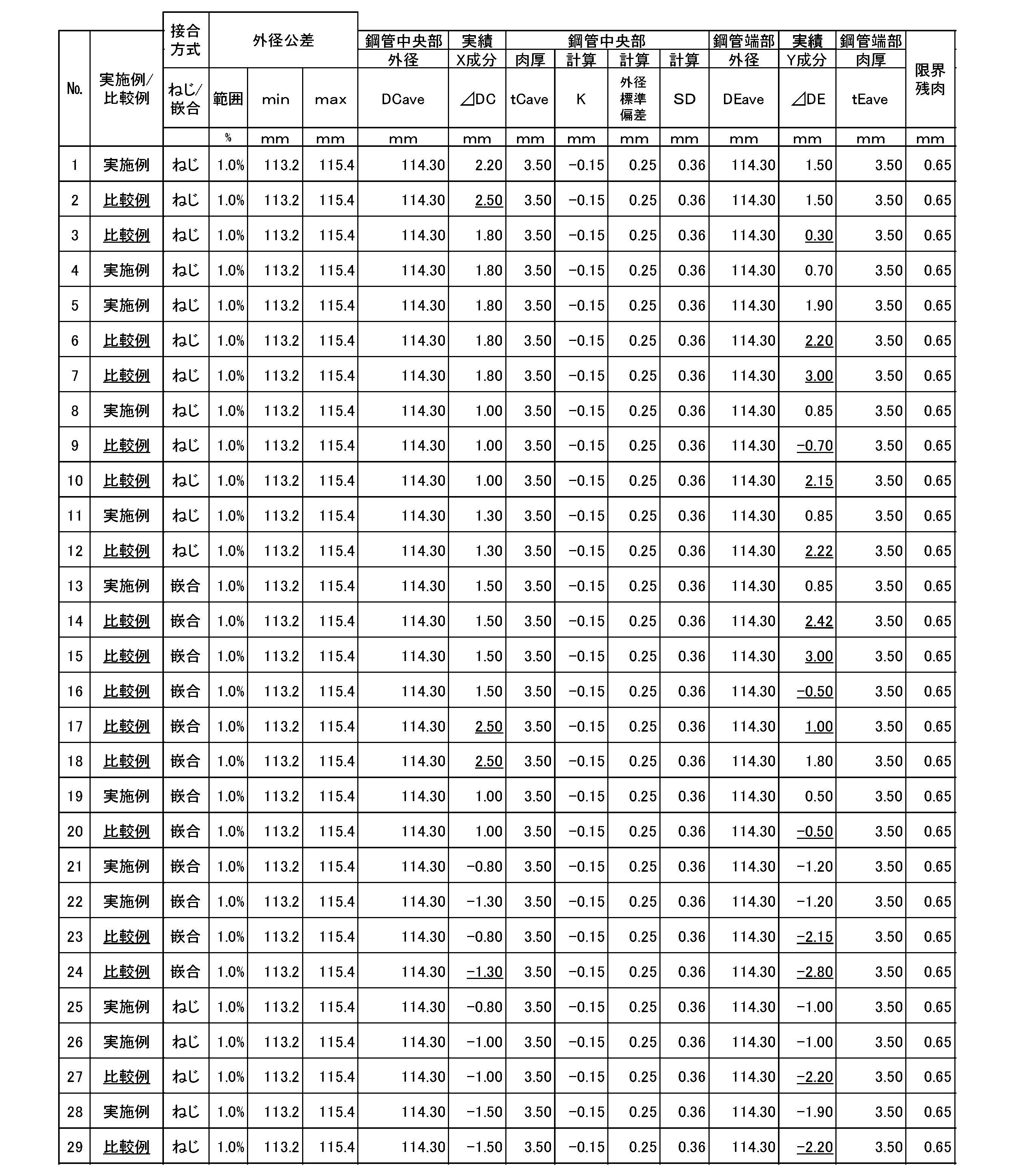
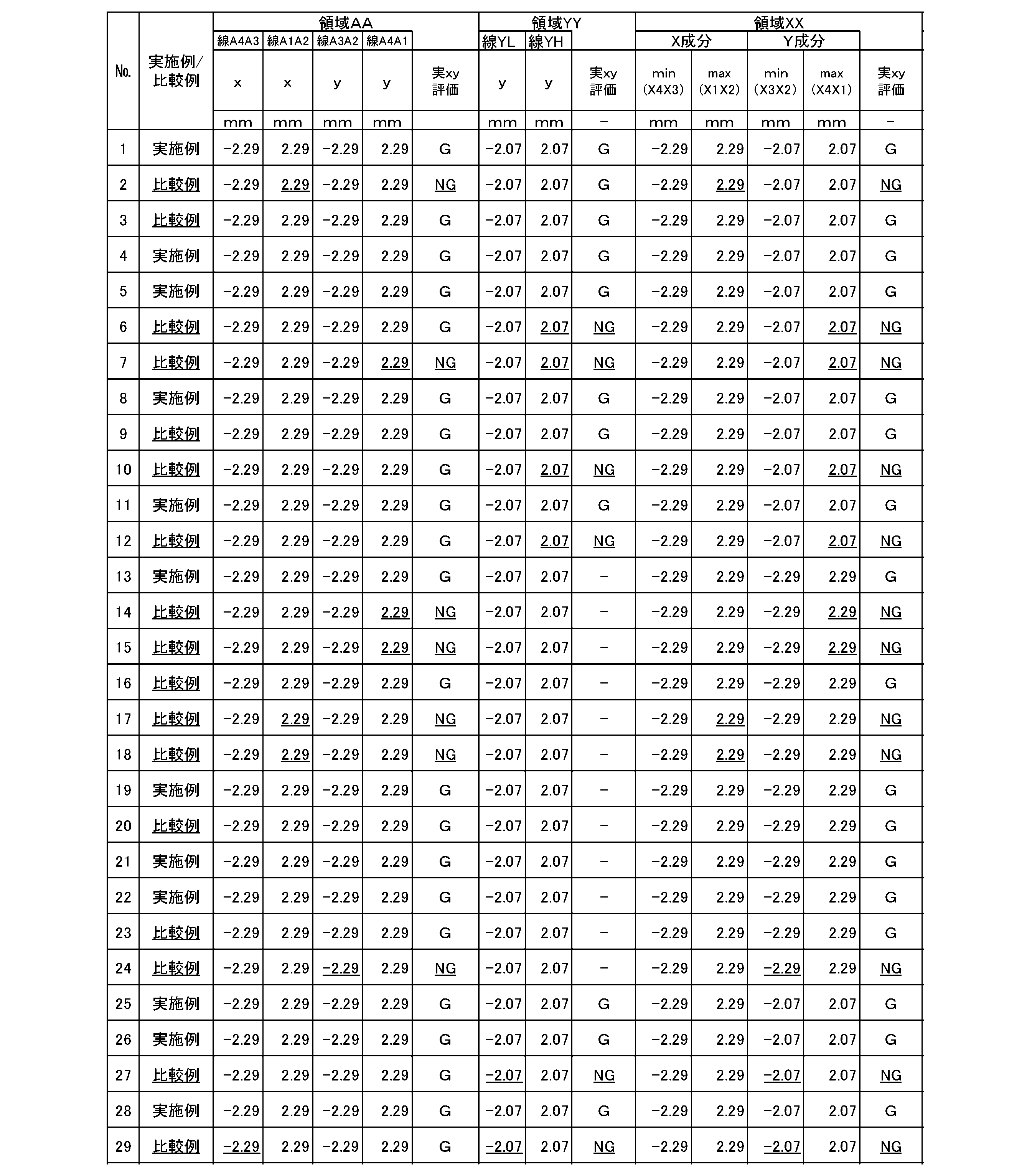

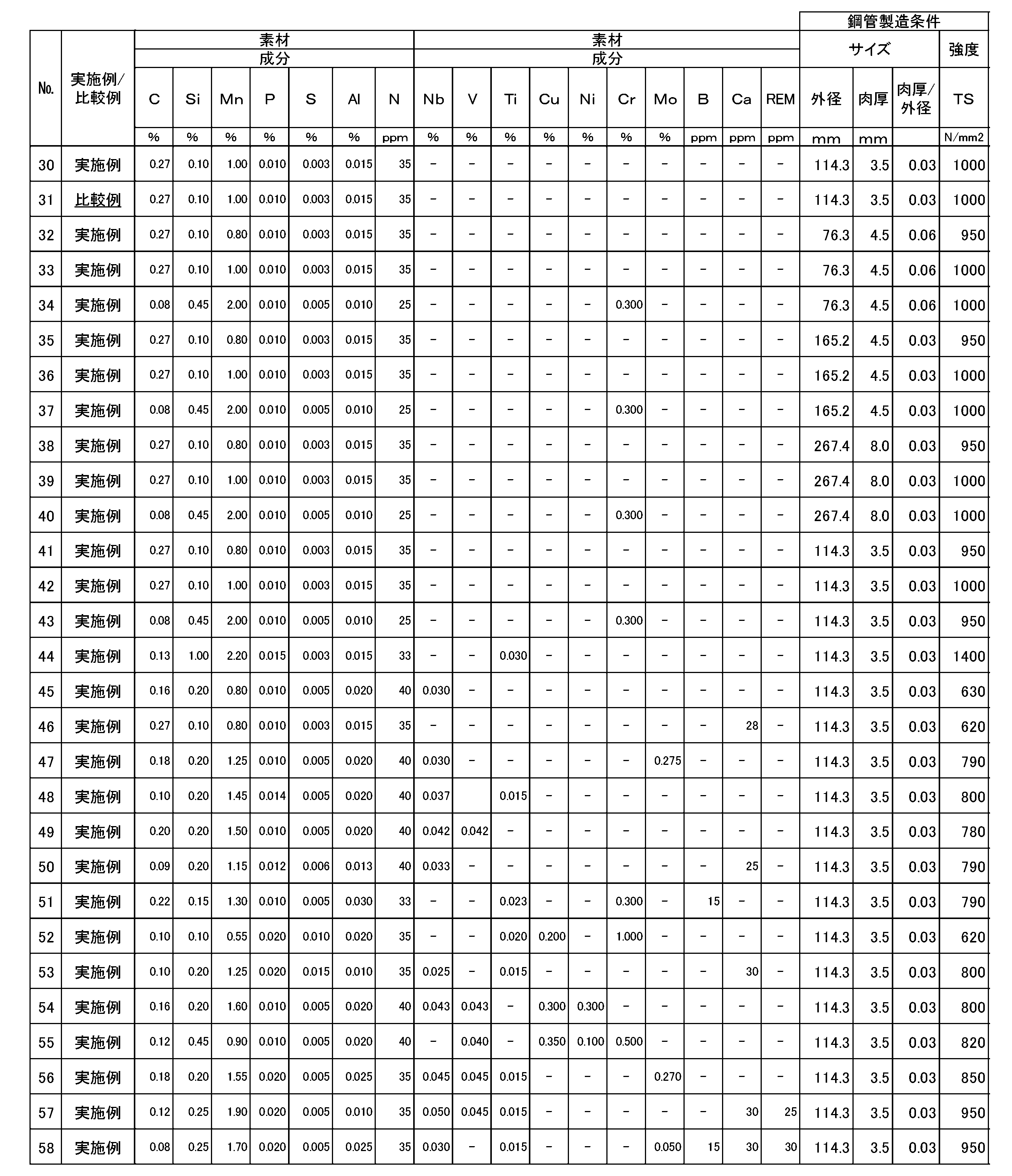
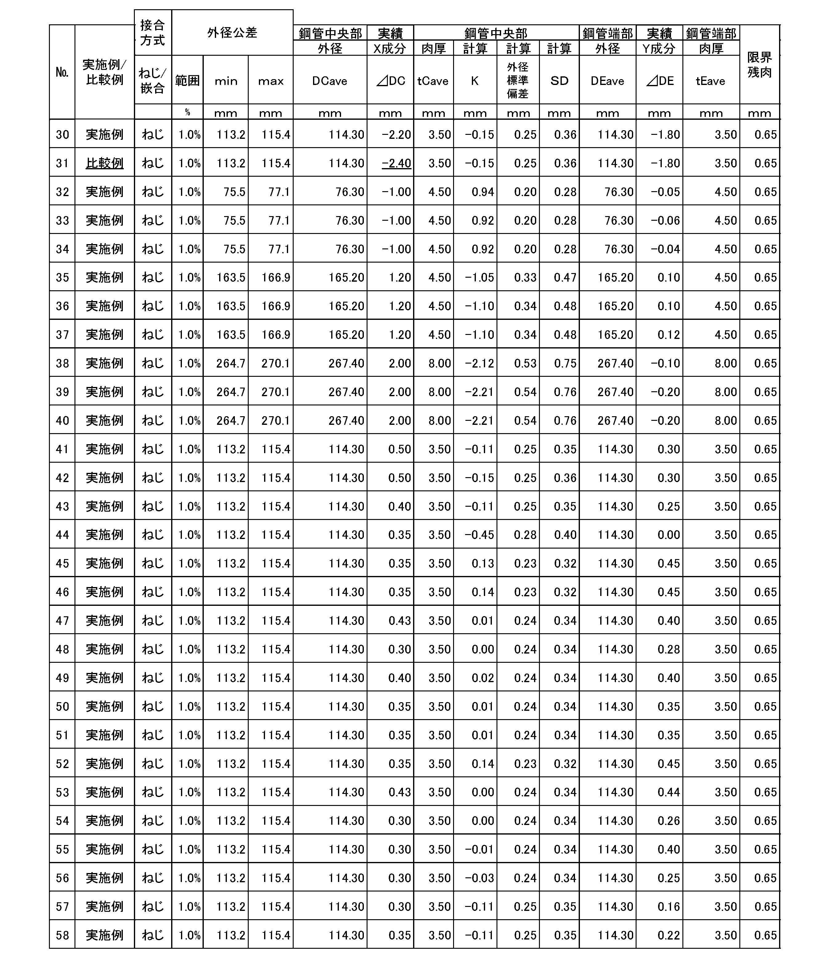


領域AAを満足できない場合は、鋼管端部および鋼管中央部ともに必要な外径公差が確保できない、このことは鋼管の外径測定で判定可能である。この場合は、構造管として使用する際に、必要な円形の形状を確保できないため、必要な曲げモーメントまたは曲げ耐力が確保できず、使用時に変形や座屈が発生し構造管として必要な機能が満足できない。
領域YYを満足できない場合は、ねじとして必要な残肉が確保できず、ねじ加工時には変形が生じることがあり、また使用時には接続不良などねじの機能が確保できない。このことはねじゲージなどでの寸法測定、目視で判定可能である。また、管体としては、必要な残肉が確保できないため継手の強度が確保できず、使用時に継手部の曲りなどの変形、破断などが発生し、本来の用途としての機能を確保することができない。このことは、目視で判定可能である。
領域XXを満足できない場合は、つまりは、領域AA、領域YYのいずれか一方もしくは両方が満足できない場合であり、その場合は、それぞれが満足できなかった不良が発生する。
領域WWを満足できない場合は、今回の発明で得られた鋼管中央部と鋼管端部の縦楕円度の関係から操業結果が外れることで、正しい成形が行われないことである。これは、製品の局部的な形状不良や設備の異常などにより、製造が正しく行われていないことを意味しており、製造ロットの中で一定の品質が得られていないため製品とすることはできない。このことは、製品の目視検査、設備の点検で判定可能である。また領域WWを満足できない場合は、正しい成形が行われていないので、ねじ加工に必要な鋼管の形状が出来ないため、ねじ加工時には変形が生じることがあり、また使用時には接続不良などねじの機能が確保できない、また、外径公差が製造ロットの中で一定の値として確保できないので、それらを満足することができない。変形のないねじ加工の実施、外径公差の確保には、領域WWの確保が前提となる。
表1の実施例における鋼管の評価として、ねじ加工状況と鋼管外径公差の確保を示す。鋼管外径公差の確保とは、鋼管端部と鋼管中央部の両方が外径公差を満足した場合である。
ねじ加工状況では、正しい成形が行われ鋼管製品として一定の品質が確保される条件である領域WWを満足し、かつ、ねじとして必要な残肉が確保できる条件である領域YYが同時に満足できる場合に良好なねじ加工が可能となる。鋼管外径公差の確保では、正しい成形が行われ鋼管製品として一定の品質が確保される条件である領域WWを満足し、かつ、外径公差が確保される条件である領域AAが同時に満足できる場合に鋼管外径公差の確保が可能となる。
ねじ加工状況では、正しい成形が行われ鋼管製品として一定の品質が確保される条件である領域WWを満足し、かつ、ねじとして必要な残肉が確保できる条件である領域YYが同時に満足できる場合に良好なねじ加工が可能となる。鋼管外径公差の確保では、正しい成形が行われ鋼管製品として一定の品質が確保される条件である領域WWを満足し、かつ、外径公差が確保される条件である領域AAが同時に満足できる場合に鋼管外径公差の確保が可能となる。
領域PPを満足できない場合は、つまりは、領域XX、領域WWのいずれか一方もしくは両方が満足できない場合であり、その場合は、それぞれが満足できなかった不良が発生する。領域XXのみ満足しない場合は、ねじとして必要な残肉が確保できず、ねじ加工時には変形が生じることがあり、また使用時には接続不良などねじの機能が確保できない。
領域WWのみ満足しない場合は、正しい成形が行われていないので、ねじ加工に必要な鋼管の形状が出来ないため、ねじ加工時には変形が生じることがあり、また使用時には接続不良などねじの機能が確保できない。それと同時に、外径公差が製造ロットの中で一定の値として確保できないので、外径公差も満足することができない。領域XXおよび領域WWの両方が満足しない場合は、ねじ加工にねじとして必要な残肉が確保できず、それによるねじ加工時には変形が生じる。また、必要な鋼管の形状が出来ないため、ねじ加工時には変形が生じることがあり、両方の理由で、使用時には接続不良などねじの機能が確保できない。それと同時に、外径公差が製造ロットの中で一定の値として確保できないので、外径公差も満足することができない。
領域WWのみ満足しない場合は、正しい成形が行われていないので、ねじ加工に必要な鋼管の形状が出来ないため、ねじ加工時には変形が生じることがあり、また使用時には接続不良などねじの機能が確保できない。それと同時に、外径公差が製造ロットの中で一定の値として確保できないので、外径公差も満足することができない。領域XXおよび領域WWの両方が満足しない場合は、ねじ加工にねじとして必要な残肉が確保できず、それによるねじ加工時には変形が生じる。また、必要な鋼管の形状が出来ないため、ねじ加工時には変形が生じることがあり、両方の理由で、使用時には接続不良などねじの機能が確保できない。それと同時に、外径公差が製造ロットの中で一定の値として確保できないので、外径公差も満足することができない。
領域ZZはより良い実施例の範囲であり、領域ZZを外れても、領域XXかつWWの範囲内であれば、実施例である。
尚、表1の比較例のNo.2とNo.31について説明する。この比較例では、鋼管外径公差が「不良」であるが、ねじ加工状況は「良好」となっている。これは、鋼管中央部では外径公差を満足しないが、鋼管端部での外径公差は満足できた場合である。この実施例では、領域WWと領域YYは満足しているため、ねじ切りは可能となる。但し、鋼管中央部の外径公差が満足できていないので、外径公差は「不良」であり、構造管として必要な機能を満足しないため、製品にはなりえず比較例となる。
以上、添付図面を参照しながら本発明の好適な実施形態について詳細に説明したが、本発明はかかる例に限定されない。本発明の属する技術の分野における通常の知識を有する者であれば、請求の範囲に記載された技術的思想の範疇内において、各種の変更例または修正例に想到し得ることは明らかであり、これらについても、当然に本発明の技術的範囲に属するものと了解される。
本発明によれば、軽量高強度であって、造管後の新たな切断によって発生する鋼管端部が高真円度の高強度電縫鋼管および地盤安定化工事用高強度電縫鋼管の使用方法を提供することができる。よって、産業上の利用可能性は大である。
Claims (6)
- 質量%または質量ppmで
C:0.04~0.30%、
Si:0.01~2.00%、
Mn:0.50~3.00%、
P:0.030%以下、
S:0.030%以下、
Al:0.005~0.700%、
N:100ppm以下、
Nb:0~0.100%、
V:0~0.100%、
Ti:0~0.200%、
Ni:0~1.000%、
Cu:0~1.000%、
Cr:0~1.000%、
Mo:0~1.000%、
B:0~50ppm、
Ca:0~100ppmおよび
REM:0~200ppm
を含有し、残部が鉄および不純物からなり、
DCaveが60.3mm以上318.5mm以下であり、tCave/DCaveが0.02以上0.06以下であり、引張強さが590N/mm2以上であり、鋼管中央部を切断した場合、下記式を満足することを特徴とする高強度電縫鋼管。
DCave×(-2/100)≦x≦DCave×(2/100) (1)
YN≦y≦YM (2)
x+K-3×SD≦y≦x+K+3×SD (3)
YM=MIN[{DEave×(2/100)}、{4×((tEave/3)-0.65)}] (4)
ここで(4)式は{DEave×(2/100)}と{4×((tEave/3)-0.65)}の小さい方をYMとする。
YN=MAX[{DEave×(-2/100)}、{-4×((tEave/3)-0.65)}](5)
ここで(5)式は{DEave×(-2/100)}と{-4×((tEave/3)-0.65)}の大きい方をYNとする。
K={α+(β/I)+(γ×TS)}×DCave (6)
SD=(√2)×(鋼管中央部の平均外径DCaveの標準偏差) (7)
鋼管中央部の外径の標準偏差={p+(q/I)+(r×TS)}×DCave (8)
ここでx:縦楕円度(鋼管中央部)、y:縦楕円度(鋼管端部)、DCave:造管後、切断前の鋼管中央部の平均外径(mm)、tCave:造管後、切断前の鋼管中央部の鋼管の平均肉厚(mm)、DEave:造管後、切断後の鋼管端部の平均外径(mm)、tEave:造管後、切断後の鋼管端部の平均肉厚(mm)、TS:高強度電縫鋼管の母材部の引張強さ(N/mm2)、α、β、γは定数で、
α=-1.87×10⁻³ (9)
β=1.35×10⁴ (10)
γ=-6.65×10⁻⁶ (11)
Iは鋼管中央部断面の断面二次モーメント(mm4)で、
I=π/64×{(DCave)4-(DCave-2×tCave)4} (12)
p、q、rは定数で
p=1.39×10⁻³ (13)
q=4.17×10² (14)
r=6.05×10⁻⁷ (15)
である。 - 引張強さが780N/mm2以上であることを特徴とする請求項1に記載の高強度電縫鋼管。
- さらに下記式を満足することを特徴とする請求項1または2に記載の高強度電縫鋼管。
YN-K+3×SD≦x≦YM-K-3×SD (17) - さらに下記式を満足することを特徴とする請求項1または2に記載の高強度電縫鋼管。
DEave×(-2/100)-K+3×SD≦x
≦DEave×(2/100)-K-3×SD (18) - 請求項1または2に記載の高強度電縫鋼管の鋼管中央部で切断して発生した新たな鋼管端部にねじ切りを行ない、ねじ継手で2本以上の高強度電縫鋼管を接続して用いることを特徴とする地盤安定化工事用高強度電縫鋼管の使用方法。
- 請求項1または2に記載の高強度電縫鋼管の鋼管端部の一方または両方が鋼管中央部で切断して発生した新たな鋼管端部に、当該鋼管端部同士を1ないし複数の治具を介して嵌合させて2本以上の高強度電縫鋼管を接続して用いることを特徴とする地盤安定化工事用高強度電縫鋼管の使用方法。
Priority Applications (3)
| Application Number | Priority Date | Filing Date | Title |
|---|---|---|---|
| JP2020564021A JP6841392B2 (ja) | 2019-02-21 | 2020-02-21 | 高強度電縫鋼管および地盤安定化工事用高強度電縫鋼管の使用方法 |
| CN202080014708.6A CN113423846B (zh) | 2019-02-21 | 2020-02-21 | 高强度电焊钢管和地基稳定化工程用高强度电焊钢管的使用方法 |
| MYPI2021004238A MY205932A (en) | 2019-02-21 | 2020-02-21 | High-strength electric-resistance-welded steel pipe and method for using high-strength electric-resistance-welded steel pipe in construction work to stabilize foundation |
Applications Claiming Priority (2)
| Application Number | Priority Date | Filing Date | Title |
|---|---|---|---|
| JP2019-029437 | 2019-02-21 | ||
| JP2019029437 | 2019-02-21 |
Publications (1)
| Publication Number | Publication Date |
|---|---|
| WO2020171209A1 true WO2020171209A1 (ja) | 2020-08-27 |
Family
ID=72144899
Family Applications (1)
| Application Number | Title | Priority Date | Filing Date |
|---|---|---|---|
| PCT/JP2020/007101 Ceased WO2020171209A1 (ja) | 2019-02-21 | 2020-02-21 | 高強度電縫鋼管および地盤安定化工事用高強度電縫鋼管の使用方法 |
Country Status (4)
| Country | Link |
|---|---|
| JP (1) | JP6841392B2 (ja) |
| CN (1) | CN113423846B (ja) |
| MY (1) | MY205932A (ja) |
| WO (1) | WO2020171209A1 (ja) |
Cited By (1)
| Publication number | Priority date | Publication date | Assignee | Title |
|---|---|---|---|---|
| JP2024545450A (ja) * | 2021-12-16 | 2024-12-06 | ポスコ カンパニー リミテッド | 地盤補強用熱延鋼板及び鋼管とこれらの製造方法 |
Citations (6)
| Publication number | Priority date | Publication date | Assignee | Title |
|---|---|---|---|---|
| WO2012133558A1 (ja) * | 2011-03-30 | 2012-10-04 | 新日本製鐵株式会社 | 電縫鋼管及びその製造方法 |
| WO2015022899A1 (ja) * | 2013-08-16 | 2015-02-19 | 新日鐵住金株式会社 | 溶接部品質の優れた電縫鋼管及びその製造方法 |
| JP2016047956A (ja) * | 2014-08-28 | 2016-04-07 | Jfeスチール株式会社 | 低降伏比高強度スパイラル鋼管杭およびその製造方法 |
| JP2017166064A (ja) * | 2016-03-09 | 2017-09-21 | Jfeスチール株式会社 | 非調質低降伏比高張力厚鋼板およびその製造方法ならびに形鋼および構造体 |
| WO2017163987A1 (ja) * | 2016-03-22 | 2017-09-28 | 新日鐵住金株式会社 | ラインパイプ用電縫鋼管 |
| JP2018053281A (ja) * | 2016-09-27 | 2018-04-05 | 新日鐵住金株式会社 | 角形鋼管 |
Family Cites Families (7)
| Publication number | Priority date | Publication date | Assignee | Title |
|---|---|---|---|---|
| JP4500193B2 (ja) * | 2005-03-28 | 2010-07-14 | 新日本製鐵株式会社 | 機械構造部材用鋼管の製造方法 |
| CN101248202A (zh) * | 2005-08-22 | 2008-08-20 | 新日本制铁株式会社 | 淬透性、热加工性及疲劳强度优异的高强度厚壁电焊钢管及其制造方法 |
| CN105473230A (zh) * | 2013-08-14 | 2016-04-06 | 迪耐斯公司 | 涂覆的颗粒过滤器 |
| CN104089109B (zh) * | 2014-06-30 | 2017-06-23 | 宝山钢铁股份有限公司 | 一种625MPa级UOE焊管及其制造方法 |
| JP6015879B1 (ja) * | 2014-12-25 | 2016-10-26 | Jfeスチール株式会社 | 深井戸向けコンダクターケーシング用高強度厚肉電縫鋼管およびその製造方法並びに深井戸向け高強度厚肉コンダクターケーシング |
| PL3358028T3 (pl) * | 2015-09-29 | 2021-05-31 | Jfe Steel Corporation | Rura stalowa zgrzewana elektrycznie oporowo dla pustego w środku stabilizatora o dużej wytrzymałości, sposób wytwarzania rury stalowej zgrzewanej elektrycznie oporowo dla pustego w środku stabilizatora o dużej wytrzymałości, pusty w środku stabilizator o dużej wytrzymałości i sposób wytwarzania pustego w środku stabilizatora o dużej wytrzymałości |
| MX2018015659A (es) * | 2016-06-22 | 2019-03-14 | Jfe Steel Corp | Lamina de acero laminada en caliente para tuberia de conduccion de alta resistencia de gran espesor, tuberia de acero soldada para tuberia de conduccion de alta resistencia de gran espesor, y metodo para producir la tuberia de acero soldada. |
-
2020
- 2020-02-21 WO PCT/JP2020/007101 patent/WO2020171209A1/ja not_active Ceased
- 2020-02-21 CN CN202080014708.6A patent/CN113423846B/zh active Active
- 2020-02-21 JP JP2020564021A patent/JP6841392B2/ja active Active
- 2020-02-21 MY MYPI2021004238A patent/MY205932A/en unknown
Patent Citations (6)
| Publication number | Priority date | Publication date | Assignee | Title |
|---|---|---|---|---|
| WO2012133558A1 (ja) * | 2011-03-30 | 2012-10-04 | 新日本製鐵株式会社 | 電縫鋼管及びその製造方法 |
| WO2015022899A1 (ja) * | 2013-08-16 | 2015-02-19 | 新日鐵住金株式会社 | 溶接部品質の優れた電縫鋼管及びその製造方法 |
| JP2016047956A (ja) * | 2014-08-28 | 2016-04-07 | Jfeスチール株式会社 | 低降伏比高強度スパイラル鋼管杭およびその製造方法 |
| JP2017166064A (ja) * | 2016-03-09 | 2017-09-21 | Jfeスチール株式会社 | 非調質低降伏比高張力厚鋼板およびその製造方法ならびに形鋼および構造体 |
| WO2017163987A1 (ja) * | 2016-03-22 | 2017-09-28 | 新日鐵住金株式会社 | ラインパイプ用電縫鋼管 |
| JP2018053281A (ja) * | 2016-09-27 | 2018-04-05 | 新日鐵住金株式会社 | 角形鋼管 |
Cited By (2)
| Publication number | Priority date | Publication date | Assignee | Title |
|---|---|---|---|---|
| JP2024545450A (ja) * | 2021-12-16 | 2024-12-06 | ポスコ カンパニー リミテッド | 地盤補強用熱延鋼板及び鋼管とこれらの製造方法 |
| JP7838851B2 (ja) | 2021-12-16 | 2026-04-01 | ポスコ カンパニー リミテッド | 地盤補強用熱延鋼板及び鋼管とこれらの製造方法 |
Also Published As
| Publication number | Publication date |
|---|---|
| MY205932A (en) | 2024-11-21 |
| CN113423846B (zh) | 2022-09-20 |
| JPWO2020171209A1 (ja) | 2021-03-11 |
| JP6841392B2 (ja) | 2021-03-10 |
| CN113423846A (zh) | 2021-09-21 |
Similar Documents
| Publication | Publication Date | Title |
|---|---|---|
| EP3042976B1 (en) | Steel sheet for thick-walled high-strength line pipe having exceptional corrosion resistance, crush resistance properties, and low-temperature ductility, and line pipe | |
| JP5679091B1 (ja) | 熱延鋼板およびその製造方法 | |
| JP5783229B2 (ja) | 熱延鋼板およびその製造方法 | |
| EP2395122B1 (en) | High-strength steel tube for low-temperature use with superior buckling resistance and toughness in weld heat-affected areas, and manufacturing method for same | |
| JP4671959B2 (ja) | 低温靱性に優れた超高強度ラインパイプ用鋼板及び鋼管並びにそれらの製造方法 | |
| EP2392681B1 (en) | Heavy gauge, high tensile strength, hot rolled steel sheet with excellent hic resistance and manufacturing method therefor | |
| JP6369658B1 (ja) | 鋼管及び鋼板 | |
| CN108495945B (zh) | 电阻焊钢管用高强度热轧钢板及其制造方法 | |
| CN101448967B (zh) | 抗应变时效性优异的高强度管线管用钢管和高强度管线管用钢板以及它们的制造方法 | |
| JP5516834B1 (ja) | 電縫溶接鋼管 | |
| EP2392682A1 (en) | Thick high-tensile-strength hot-rolled steel sheet with excellent low-temperature toughness and process for production of same | |
| JP6816827B2 (ja) | 角鋼管の製造方法および角鋼管 | |
| KR20120084804A (ko) | 높은 압축 강도 및 내사우어성이 우수한 라인파이프용 용접 강관 및 그 제조 방법 | |
| EP3375900A1 (en) | Electric resistance welded steel tube for line pipe | |
| JP5768603B2 (ja) | 高一様伸び特性を備え、かつ溶接部低温靱性に優れた高強度溶接鋼管、およびその製造方法 | |
| EP3428299A1 (en) | Electroseamed steel pipe for line pipe | |
| US11028456B2 (en) | Electric resistance welded steel pipe for torsion beam | |
| KR20230059820A (ko) | 각형 강관 및 그 제조 방법 그리고 건축 구조물 | |
| JPWO2019220577A1 (ja) | トーションビーム用アズロール電縫鋼管 | |
| WO2020170774A1 (ja) | 角形鋼管およびその製造方法、並びに建築構造物 | |
| JP6841392B2 (ja) | 高強度電縫鋼管および地盤安定化工事用高強度電縫鋼管の使用方法 | |
| JP6693610B1 (ja) | ラインパイプ用電縫鋼管 | |
| WO2013111902A1 (ja) | パイプライン及びその製造方法 | |
| JP5842473B2 (ja) | 高一様伸び特性を備えかつ溶接部靱性に優れた高強度溶接鋼管、およびその製造方法 | |
| EP4206338A1 (en) | Electric resistance welded steel pipe |
Legal Events
| Date | Code | Title | Description |
|---|---|---|---|
| 121 | Ep: the epo has been informed by wipo that ep was designated in this application |
Ref document number: 20760033 Country of ref document: EP Kind code of ref document: A1 |
|
| ENP | Entry into the national phase |
Ref document number: 2020564021 Country of ref document: JP Kind code of ref document: A |
|
| NENP | Non-entry into the national phase |
Ref country code: DE |
|
| 122 | Ep: pct application non-entry in european phase |
Ref document number: 20760033 Country of ref document: EP Kind code of ref document: A1 |