WO2020171052A1 - 共培養用デバイス、運動神経細胞培養用デバイス、マルチウェルプレート、神経筋疾患のin vitro評価モデルの作製方法、および、神経筋疾患の治療薬のスクリーニング方法 - Google Patents
共培養用デバイス、運動神経細胞培養用デバイス、マルチウェルプレート、神経筋疾患のin vitro評価モデルの作製方法、および、神経筋疾患の治療薬のスクリーニング方法 Download PDFInfo
- Publication number
- WO2020171052A1 WO2020171052A1 PCT/JP2020/006221 JP2020006221W WO2020171052A1 WO 2020171052 A1 WO2020171052 A1 WO 2020171052A1 JP 2020006221 W JP2020006221 W JP 2020006221W WO 2020171052 A1 WO2020171052 A1 WO 2020171052A1
- Authority
- WO
- WIPO (PCT)
- Prior art keywords
- unit
- axon
- skeletal muscle
- motor neurons
- muscle tissue
- Prior art date
- Legal status (The legal status is an assumption and is not a legal conclusion. Google has not performed a legal analysis and makes no representation as to the accuracy of the status listed.)
- Ceased
Links
Images










Classifications
-
- C—CHEMISTRY; METALLURGY
- C12—BIOCHEMISTRY; BEER; SPIRITS; WINE; VINEGAR; MICROBIOLOGY; ENZYMOLOGY; MUTATION OR GENETIC ENGINEERING
- C12M—APPARATUS FOR ENZYMOLOGY OR MICROBIOLOGY; APPARATUS FOR CULTURING MICROORGANISMS FOR PRODUCING BIOMASS, FOR GROWING CELLS OR FOR OBTAINING FERMENTATION OR METABOLIC PRODUCTS, i.e. BIOREACTORS OR FERMENTERS
- C12M21/00—Bioreactors or fermenters specially adapted for specific uses
- C12M21/08—Bioreactors or fermenters specially adapted for specific uses for producing artificial tissue or for ex-vivo cultivation of tissue
-
- G—PHYSICS
- G01—MEASURING; TESTING
- G01N—INVESTIGATING OR ANALYSING MATERIALS BY DETERMINING THEIR CHEMICAL OR PHYSICAL PROPERTIES
- G01N33/00—Investigating or analysing materials by specific methods not covered by groups G01N1/00 - G01N31/00
- G01N33/48—Biological material, e.g. blood, urine; Haemocytometers
- G01N33/50—Chemical analysis of biological material, e.g. blood, urine; Testing involving biospecific ligand binding methods; Immunological testing
- G01N33/5005—Chemical analysis of biological material, e.g. blood, urine; Testing involving biospecific ligand binding methods; Immunological testing involving human or animal cells
- G01N33/5008—Chemical analysis of biological material, e.g. blood, urine; Testing involving biospecific ligand binding methods; Immunological testing involving human or animal cells for testing or evaluating the effect of chemical or biological compounds, e.g. drugs, cosmetics
- G01N33/5044—Chemical analysis of biological material, e.g. blood, urine; Testing involving biospecific ligand binding methods; Immunological testing involving human or animal cells for testing or evaluating the effect of chemical or biological compounds, e.g. drugs, cosmetics involving specific cell types
- G01N33/5058—Neurological cells
-
- C—CHEMISTRY; METALLURGY
- C12—BIOCHEMISTRY; BEER; SPIRITS; WINE; VINEGAR; MICROBIOLOGY; ENZYMOLOGY; MUTATION OR GENETIC ENGINEERING
- C12M—APPARATUS FOR ENZYMOLOGY OR MICROBIOLOGY; APPARATUS FOR CULTURING MICROORGANISMS FOR PRODUCING BIOMASS, FOR GROWING CELLS OR FOR OBTAINING FERMENTATION OR METABOLIC PRODUCTS, i.e. BIOREACTORS OR FERMENTERS
- C12M23/00—Constructional details, e.g. recesses, hinges
- C12M23/02—Form or structure of the vessel
- C12M23/12—Well or multiwell plates
-
- C—CHEMISTRY; METALLURGY
- C12—BIOCHEMISTRY; BEER; SPIRITS; WINE; VINEGAR; MICROBIOLOGY; ENZYMOLOGY; MUTATION OR GENETIC ENGINEERING
- C12M—APPARATUS FOR ENZYMOLOGY OR MICROBIOLOGY; APPARATUS FOR CULTURING MICROORGANISMS FOR PRODUCING BIOMASS, FOR GROWING CELLS OR FOR OBTAINING FERMENTATION OR METABOLIC PRODUCTS, i.e. BIOREACTORS OR FERMENTERS
- C12M23/00—Constructional details, e.g. recesses, hinges
- C12M23/02—Form or structure of the vessel
- C12M23/16—Microfluidic devices; Capillary tubes
-
- C—CHEMISTRY; METALLURGY
- C12—BIOCHEMISTRY; BEER; SPIRITS; WINE; VINEGAR; MICROBIOLOGY; ENZYMOLOGY; MUTATION OR GENETIC ENGINEERING
- C12M—APPARATUS FOR ENZYMOLOGY OR MICROBIOLOGY; APPARATUS FOR CULTURING MICROORGANISMS FOR PRODUCING BIOMASS, FOR GROWING CELLS OR FOR OBTAINING FERMENTATION OR METABOLIC PRODUCTS, i.e. BIOREACTORS OR FERMENTERS
- C12M23/00—Constructional details, e.g. recesses, hinges
- C12M23/34—Internal compartments or partitions
-
- C—CHEMISTRY; METALLURGY
- C12—BIOCHEMISTRY; BEER; SPIRITS; WINE; VINEGAR; MICROBIOLOGY; ENZYMOLOGY; MUTATION OR GENETIC ENGINEERING
- C12M—APPARATUS FOR ENZYMOLOGY OR MICROBIOLOGY; APPARATUS FOR CULTURING MICROORGANISMS FOR PRODUCING BIOMASS, FOR GROWING CELLS OR FOR OBTAINING FERMENTATION OR METABOLIC PRODUCTS, i.e. BIOREACTORS OR FERMENTERS
- C12M23/00—Constructional details, e.g. recesses, hinges
- C12M23/58—Reaction vessels connected in series or in parallel
-
- C—CHEMISTRY; METALLURGY
- C12—BIOCHEMISTRY; BEER; SPIRITS; WINE; VINEGAR; MICROBIOLOGY; ENZYMOLOGY; MUTATION OR GENETIC ENGINEERING
- C12M—APPARATUS FOR ENZYMOLOGY OR MICROBIOLOGY; APPARATUS FOR CULTURING MICROORGANISMS FOR PRODUCING BIOMASS, FOR GROWING CELLS OR FOR OBTAINING FERMENTATION OR METABOLIC PRODUCTS, i.e. BIOREACTORS OR FERMENTERS
- C12M25/00—Means for supporting, enclosing or fixing the microorganisms, e.g. immunocoatings
-
- C—CHEMISTRY; METALLURGY
- C12—BIOCHEMISTRY; BEER; SPIRITS; WINE; VINEGAR; MICROBIOLOGY; ENZYMOLOGY; MUTATION OR GENETIC ENGINEERING
- C12M—APPARATUS FOR ENZYMOLOGY OR MICROBIOLOGY; APPARATUS FOR CULTURING MICROORGANISMS FOR PRODUCING BIOMASS, FOR GROWING CELLS OR FOR OBTAINING FERMENTATION OR METABOLIC PRODUCTS, i.e. BIOREACTORS OR FERMENTERS
- C12M25/00—Means for supporting, enclosing or fixing the microorganisms, e.g. immunocoatings
- C12M25/14—Scaffolds; Matrices
-
- C—CHEMISTRY; METALLURGY
- C12—BIOCHEMISTRY; BEER; SPIRITS; WINE; VINEGAR; MICROBIOLOGY; ENZYMOLOGY; MUTATION OR GENETIC ENGINEERING
- C12M—APPARATUS FOR ENZYMOLOGY OR MICROBIOLOGY; APPARATUS FOR CULTURING MICROORGANISMS FOR PRODUCING BIOMASS, FOR GROWING CELLS OR FOR OBTAINING FERMENTATION OR METABOLIC PRODUCTS, i.e. BIOREACTORS OR FERMENTERS
- C12M35/00—Means for application of stress for stimulating the growth of microorganisms or the generation of fermentation or metabolic products; Means for electroporation or cell fusion
- C12M35/08—Chemical, biochemical or biological means, e.g. plasma jet, co-culture
-
- G—PHYSICS
- G01—MEASURING; TESTING
- G01N—INVESTIGATING OR ANALYSING MATERIALS BY DETERMINING THEIR CHEMICAL OR PHYSICAL PROPERTIES
- G01N33/00—Investigating or analysing materials by specific methods not covered by groups G01N1/00 - G01N31/00
- G01N33/15—Medicinal preparations ; Physical properties thereof, e.g. dissolubility
-
- G—PHYSICS
- G01—MEASURING; TESTING
- G01N—INVESTIGATING OR ANALYSING MATERIALS BY DETERMINING THEIR CHEMICAL OR PHYSICAL PROPERTIES
- G01N33/00—Investigating or analysing materials by specific methods not covered by groups G01N1/00 - G01N31/00
- G01N33/48—Biological material, e.g. blood, urine; Haemocytometers
- G01N33/50—Chemical analysis of biological material, e.g. blood, urine; Testing involving biospecific ligand binding methods; Immunological testing
- G01N33/5005—Chemical analysis of biological material, e.g. blood, urine; Testing involving biospecific ligand binding methods; Immunological testing involving human or animal cells
- G01N33/5008—Chemical analysis of biological material, e.g. blood, urine; Testing involving biospecific ligand binding methods; Immunological testing involving human or animal cells for testing or evaluating the effect of chemical or biological compounds, e.g. drugs, cosmetics
- G01N33/5082—Supracellular entities, e.g. tissue, organisms
-
- G—PHYSICS
- G01—MEASURING; TESTING
- G01N—INVESTIGATING OR ANALYSING MATERIALS BY DETERMINING THEIR CHEMICAL OR PHYSICAL PROPERTIES
- G01N37/00—Details not covered by any other group of this subclass
Definitions
- the disclosure in the present application relates to a device for co-culture, a device for culturing motor neurons, a multi-well plate, a method for preparing an in vitro evaluation model for neuromuscular disease, and a method for screening a therapeutic agent for neuromuscular disease. More specifically, a device for co-culture and a device for culturing motoneurons for producing an in vitro evaluation model for neuromuscular diseases closer to the structure of the human body, a multi-well plate in which the device is placed in a well, and a neuromuscular
- the present invention relates to a method for screening a therapeutic agent for neuromuscular disease using an in vitro evaluation model of disease.
- NMJ neuromuscular junction
- ALS amyotrophic lateral sclerosis
- SBMA spinal and bulbar muscular atrophy
- a device for conducting research on the mechanism of onset of neuromuscular diseases and screening of therapeutic agents in vitro.
- a technique is known in which skeletal muscle cells are first cultured to prepare skeletal muscle tissue, and then motor neurons are cultured (see Non-Patent Document 1).
- the method described in Non-Patent Document 1 has a problem that the structure is different from the actual structure in the human body because the skeletal muscle tissue and the motor nerve cells are in a mixed state.
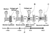
- FIG. 1 is a diagram showing another example of the conventional technology of the device (evaluation model) (see Non-Patent Document 2).
- PDMS is used to separate the skeletal muscle tissue formation compartment and the motor neuron compartment.
- skeletal muscle cells are cultured in a skeletal muscle tissue forming compartment to prepare skeletal muscle tissue (reference A).
- a motor neuron spheroid containing collagen gel is put into the motor neuron compartment (reference B).
- the motor neuron compartment is provided with a plurality of pillars (symbol P) for disposing the motor neuron spheroid at a predetermined position.
- the axon (symbol C) extending from the motor nerve cell is combined with the skeletal muscle tissue to form a neuromuscular junction.
- Y. Morimoto et al. "Three-dimensional neuronemuscle constructs with neuromuscular junctions", Biomaterials 34 (2013) 9413-9419 T. Osaki et al. , "Microphysiological 3D model of amyotropic lateral sclerosis (ALS) from human iPS-derivated muscle cells and optogeneric neurones.” Adv. 2018; 4: eaat5847.
- ALS amyotropic lateral sclerosis
- Non-Patent Document 2 arranges motor nerve cells and skeletal muscle tissue in three dimensions and uses collagen gel as a scaffold for axon extension. Therefore, it is necessary to add the collagen gel to the skeletal muscle tissue forming section, the motor nerve cell section, and the flow channel that connects the skeletal muscle tissue forming section and the motor nerve cell section.
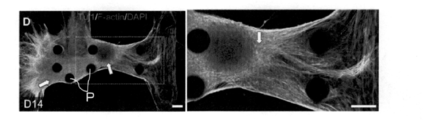
- the periphery of the motor neuron and the skeletal muscle tissue needs to be covered with a collagen gel serving as a scaffold. Therefore, even if an evaluation model in which a neuromuscular junction is formed using the device described in Non-Patent Document 2, as shown in FIG. 2, the motor neuron spheroid overcomes the pillar with time, as shown in FIG. As described above, the skeletal muscle tissue also grows and spreads, so that there is a problem that the motor nerve cells and the skeletal muscle tissue are fused. In the evaluation model described in Non-Patent Document 2, skeletal muscle tissue and the like are formed in collagen gel.
- the disclosure in the present application was made in order to solve the above problems, and when the device (evaluation model) not using collagen gel as a scaffold was earnestly studied, (1) a first culture to which a medium can be added A first unit for skeletal muscle tissue formation having a tank, (2) a second unit for motoneuron cell culture having a second culture tank to which a medium can be added, and (3) a first unit for communicating the second unit (4)
- the third unit is provided by providing (4) the third unit with an opening having an axon passage hole through which a motor neuron and a skeletal muscle cell cannot pass but an axon can pass. It was newly found that an in vitro evaluation model of neuromuscular disease used as a scaffold through which axons can pass can be created.
- the purpose of the disclosure in the present application is to provide a device for co-culturing, a device for culturing motor neurons, a multi-well plate, a method for preparing an in vitro evaluation model of neuromuscular disease, and a method for screening a therapeutic agent for neuromuscular disease. Is to provide.
- the disclosure in the present application relates to a co-culture device, a motor neuron culture device, a multi-well plate, a method for preparing an in vitro evaluation model for neuromuscular disease, and a method for screening a therapeutic agent for neuromuscular disease, which are described below. ..
- a device for co-culturing motor neurons and skeletal muscle cells The device is A first unit for forming skeletal muscle tissue, A second unit for culturing motor neurons, A third unit for connecting the first unit and the second unit, Pillars that serve as scaffolds for skeletal muscle tissue formation, Including, The first unit is A first substrate, A first culture tank formed on the first substrate, Including, The second unit is A second substrate, A second culture tank formed on the second substrate; Including, The third unit is A third substrate, An axon channel formed in the third base material, through which the bundle of axons passes, Including, One end portion of the third unit can be connected to the second unit, and when the one end portion of the third unit and the second unit are connected, the axon channel and the second culture tank can be connected to each other, A first opening is formed in the other end portion of the third unit so as to contact the axon flow path, and one or more first axon passage holes are formed in the first opening.
- the first axon passage hole cannot pass through motor neurons and skeletal muscle cells, but has a size through which axons can pass, At least a portion of the pillars can be located in the first fermentor, device.
- the axon flow path A first flow path, A second flow path formed inside the first flow path; Including, The first opening is formed so as to be in contact with the first flow path, The second channel is One end can communicate with the second culture tank, The other end is formed so as to come into contact with the second opening, In the second opening, One or more second axon passage holes are formed, The second axon passage hole has a size that allows the axon to pass though it cannot pass motor neurons and skeletal muscle cells.
- the first opening and the second opening are spaced apart, The device according to (1) above.
- Two or more third units are stacked, The device according to (1) or (2) above.
- the positional relationship among the first unit, the second unit, the third unit, and the pillar is When two or more pillars are included, they are arranged so that one of the virtual planes connecting the two or more pillars intersects with the virtual axon channel that virtually extends the axon channel to the first culture tank. , When the number of pillars is one, the virtual surface formed by one pillar or the virtual surface formed by the other end portion of the pillar and the third unit and the axon flow path are virtually extended to the first culture tank.
- Two pillars are included, one end of each pillar is connected to the first substrate 21, and the other end is arranged in a cantilever manner in the first culture tank, The device according to (4) above.
- the size of the first axon passage hole is Minimum distance is 0.5 ⁇ m or more, 2.5 ⁇ m or less, or The minimum distance is 0.5 ⁇ m or more and the cross-sectional area is 60 ⁇ m 2 or less, The device according to any one of (1) to (5) above.
- a device for motor neuron culture is produced by connecting the second unit and the third unit, Two or more motor neuron cell culture devices are arranged for one first unit, The device according to any one of (1) to (6) above.
- a motor neuron culture device is produced by connecting two or more third units to one second unit, The first unit is arranged at the other end of the optional third unit, The device according to any one of (1) to (6) above.
- a device for culturing motor neurons which is used as a device for co-culturing motor neurons and skeletal muscle cells
- the device is A second unit for culturing motor neurons, A third unit connected to the second unit, Including,
- the second unit is A second substrate, A second culture tank formed on the second substrate;
- the third unit is A third substrate, An axon channel formed in the third base material, through which the bundle of axons passes, Including, One end of the third unit is connected to the second unit, and one end of the axon channel is connected to the second culture tank, A first opening is formed in the other end portion of the third unit so as to contact the axon flow path, and one or more first axon passage holes are formed in the first opening.
- the first axon passage hole is large enough for the axon to pass through, although it cannot pass through motor neurons and skeletal muscle cells.
- device. (10) having at least two wells, The device according to any one of (1) to (9) above is arranged in at least one of the wells, Multi-well plate.
- the manufacturing method is A motor neuron culture step of culturing motor neurons in the second unit;
- An axon extending from the cell body of the cultured motor neuron passes through the axon channel of the third unit and joins with the produced skeletal muscle tissue to produce a neuromuscular junction;
- a method for producing an in vitro evaluation model for neuromuscular disease comprising: (12) A method for screening a therapeutic agent for neuromuscular disease, which uses the in vitro evaluation model for neuromuscular disease produced by the production method described in (11) above,
- the screening method is Motor neuron of the evaluation model produced, axon extending from the cell body of the motor neuron, a test substance administration step of administering the test substance to any one of skeletal muscle tissues, Motor neurons, axons
- the collagen is not used as a scaffold in the evaluation model produced using the co-culture device disclosed in the present application. Therefore, it becomes easy to observe the movement of the skeletal muscle tissue.
- FIG. 1 is a diagram illustrating an example of a conventional technique of a device (evaluation model).
- FIG. 2 is a drawing-substituting photograph, and the evaluation model produced using the device of the prior art shows that, as time elapses, motor neurons and skeletal muscle tissue are fused.
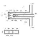
- 3A to 3H are schematic diagrams of the device 1a.
- FIG. 4A to FIG. 4C are diagrams showing an example of another embodiment of connection of one end portions of the second unit and the third unit of the device 1a.
- 5A to 5C are views for explaining the third unit in more detail.
- 6A and 6B are diagrams for explaining the first opening surface and the second opening surface of the device 1a in more detail.
- FIG. 7A and 7B are schematic cross-sectional views for explaining the device 1b according to the second embodiment.
- 8A and 8B are schematic top views for explaining the device 1c according to the third embodiment.
- FIG. 9A is a schematic top view for explaining the device 1d according to the fourth embodiment.
- 9B(a) and 9B(a) and 9(b) are views for explaining the outline of the embodiment of the multi-well plate.
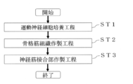
- FIG. 10 is a flowchart of an embodiment of a method for producing an evaluation model.
- FIG. 11 is a flowchart of an embodiment of the screening method.
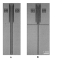
- FIG. 12 is a photograph as a substitute for a drawing, which is a photograph of the mold produced in Example 1.
- FIG. 13 is a photograph as a substitute for a drawing, which is a photograph of the device for culturing motor neurons prepared in Example 1.
- FIG. 14 is a mold drawing for producing the first unit of the first embodiment.
- FIG. 15 is a photograph as a substitute of a drawing, which is a photograph of the device manufactured in Example 1.
- FIG. 16 is a diagram showing an outline of differentiation induction in the production of the evaluation model of Example 2.
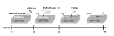
- FIG. 17 is a diagram showing the procedure of co-culturing in the production of the evaluation model of Example 2.
- FIG. 18 is a photograph as a substitute for a drawing, which is an enlarged photograph in the vicinity of the first opening of the third unit of the evaluation model manufactured in Example 2.
- FIG. 19 is a drawing-substitute photograph, in which the neuromuscular junction of the evaluation model prepared in Example 2 was stained and imaged with a confocal microscope.
- FIG. 20 is a graph showing contraction of skeletal muscle tissue before and after adding a drug to the evaluation model prepared in Example 2.
- FIG. 21 is a drawing-substituting photograph, which is a microscopic photograph after staining the axons of the evaluation model produced in Example 2.
- FIG. 22 is a photograph as a substitute for a drawing, which is a microscopic photograph confirming the rupture and regeneration of the axon of Example 3.
- a device for co-culturing hereinafter sometimes simply referred to as a “device”
- a device for culturing motor neurons hereinafter, it may be simply referred to as a “method for producing an evaluation model”.
- a screening method for a therapeutic agent for neuromuscular disease hereinafter, simply referred to as a “screening method”.
- screening method for a therapeutic agent for neuromuscular disease
- FIG. 3 is a schematic diagram of the device 1a.
- the device 1a according to the first embodiment includes a first unit 2 for forming skeletal muscle tissue, a second unit 3 for culturing motor neuron cells, and a first unit 2 for communicating the first unit 2 and the second unit. It includes 3 units 4 and pillars 23.
- 3A is a diagram showing an outline of the first unit 2
- FIG. 3B is a diagram showing an outline of the third unit 4
- FIG. 3C is a diagram showing an outline of the second unit 3. Further, FIG.
- 3D is a schematic cross-sectional view in the XX′ direction when the device 1a is manufactured by combining the first unit 2, the second unit 3, and the third unit 4.
- 3E and 3F are schematic cross-sectional views showing another embodiment of the pillar 23, and are cross-sectional views in a direction orthogonal to the XX′ direction of FIG. 3A.
- FIGS. 3G and 3H are schematic views showing another embodiment of the pillar 23, and are top views (views in the R direction of FIG. 3A) of the first unit 2.
- the first unit 2 will be described in more detail with reference to FIGS. 3A and 3D.
- the first unit 2 includes a first base material 21 and a first culture tank 22. Further, FIGS. 3A and 3D show an example in which the pillar 23 is attached to the first unit 2.
- the first culture tank 22 is used for culturing skeletal muscle cells and forming skeletal muscle tissue from the cultured skeletal muscle cells.
- the 1st culture tank 22 is formed in the 1st base material 21, and has the 1st culture medium input hole 221 in the surface above the 1st base material 21 of a substantially rectangular parallelepiped shape in the example shown to FIG. 3A and FIG. 3D. It is formed in a substantially concave shape.
- the pillar 23 is used to form skeletal muscle tissue from skeletal muscle cells cultured in the first culture tank 22.
- One end 231 of the pillar 23 is connected to the wall surface of the first substrate 21 forming the first culture tank 22, and the other end 232 is arranged in the first culture tank 22.
- the pillar 23 is arranged in a cantilever state. Therefore, skeletal muscle cells are cultured in the first culture tank 22, and the skeletal muscle tissue formed on the other end 232 of the pillar 23 is three-dimensionally formed in the first culture tank 22, in other words, the first culture tank 22. It is formed in a floating state.
- FIGS. 3A and 3D show an example in which two pillars 23 are provided.
- the formed skeletal muscle tissue can be oriented in the direction in which the pillars 23 are connected, and a tissue closer to the human skeletal muscle tissue can be formed.
- three or more pillars 23 may be provided. At that time, when it is desired to orient the produced skeletal muscle tissue in the same direction, three or more pillars 23 may be arranged linearly.
- the distance between the pillars 23 is not particularly limited as long as skeletal muscle tissue can be formed between the pillars 23, and can be, for example, 0.5 mm to 5 mm, 1 mm to 3.5 mm, and 1.5 mm to 2.6 mm.
- ⁇ m to ⁇ m it means "more than OO ⁇ m and ⁇ m or less”.
- one end 231 of the pillar 23 has a bottom surface 211 of the first base material 21 (a wall surface of the first base material 21 opposite to the first culture medium input hole 221 of the first culture tank 22 ). ) Is formed.
- the other end 232 of the pillar 23 is formed in a cantilever shape so that the other end 232 is arranged in the first culture tank 22, one end 231 may be formed on the side wall surface 212 of the first base material 21 other than the bottom surface 211. It may be formed.
- the pillar 23 when the lid is closed is formed.
- the other end 232 may be arranged in the first culture tank 22.
- FIGS. 3A to 3D an example in which two pillars 23 are arranged is shown, but one pillar 23 is formed, and one pillar 23 and the other end portion of the third unit 4 are formed.
- the skeletal muscle tissue may be formed between the skeletal muscles and the tissue 44 (the portion corresponding to the virtual axon flow path 42a in FIG. 3D).
- the one end 231 of the pillar 23 is formed on the first base material 21 or the lid 6 so that the other end 232 of the pillar 23 is arranged in the first culture tank 22.
- the arrangement and number of the pillars 23 are not particularly limited.
- both ends of one substantially U-shaped pillar 23 may be attached to the lid 6.
- both ends of one substantially U-shaped pillar 23 may be attached to the side wall surface 212 of the first base member 21.
- FIG. 3F both ends of one substantially U-shaped pillar 23 may be attached to the side wall surface 212 of the first base member 21.
- both ends of each of the two pillars 23 may be connected to the first base material 21 so as to cross the first culture tank 22. If the pillars 23 are made of a flexible material, the pillars 23 can bend in accordance with the contraction of the skeletal muscle tissue formed between the pillars 23 even in the examples shown in FIGS. 3F to 3H.
- the other end 232 of the pillar 23 may be made larger than the other portions, if necessary. By making the other end 232 larger than the other portions, the formed skeletal muscle tissue is less likely to come off the pillar 23.
- the first base material 21 and the first culture tank 22 are formed in a substantially rectangular parallelepiped shape, but if the first culture tank 22 is formed in the first base material 21.
- the shapes of the first base material 21 and the first culture tank 22 are not particularly limited.
- the pillar 23 is not particularly limited in shape as long as it can form a skeletal muscle tissue, and examples thereof include a cylindrical shape and a polygonal pillar shape.
- the notch 24 for mounting the second unit 3 described later is formed on the first base material 21, but as described later, the formation of the notch 24 is essential. is not.
- the first base material 21 and the pillar 23, or the lid 6 and the pillar 23 may be formed integrally or separately. When they are formed separately, the pillars 23 may be adhered to the wall surface of the first base material 21 or the lid 6. In addition, when the other end 232 of the pillar 23 is made large, the pillar 23 may be formed in advance so that the other end 232 becomes large, or it may be made larger by attaching another member to the other end 232 of the pillar 23. Good.
- the method of forming the first base material 21 and the pillars 23 is not particularly limited.
- a material for forming the first base material 21 is prepared and formed by cutting, and formed by a 3D printer.
- a mold may be first produced using a photolithography technique, and then the material forming the first base material 21 may be transferred.
- the material is not particularly limited as long as it can cut or transfer the mold.
- the material is not particularly limited as long as it can cut or transfer the mold.
- a resin having a light transmitting property is desirable.
- the resin in that case include cycloolefin polymer (COP), polydimethylsiloxane (PDMS), polymethylmethacrylate (PMMA), polycarbonate (PC), plastic such as hard polyethylene, and silicon. Further, metal may be used instead of resin.
- COP cycloolefin polymer
- PDMS polydimethylsiloxane
- PMMA polymethylmethacrylate
- PC polycarbonate
- plastic such as hard polyethylene
- silicon silicon
- metal may be used instead of resin.
- the second unit 3 includes the second base material 31, the second culture tank 32, and the third unit insertion portion 33 into which the one end portion 43 of the third unit 4 is inserted.
- the second culture tank 32 is used for culturing motor neurons and extending axons from the cell bodies of the cultured motor neurons.
- the 2nd culture tank 32 is formed in the 2nd base material 31, and has the 2nd culture medium input hole 321 in the upper surface of the substantially rectangular parallelepiped-shaped 2nd base material 31 in the example shown to FIG. 3C and FIG. 3D. It is formed in a substantially concave shape.
- the axon channel opening 421 is formed on the side surface 431 of the one end portion 43 of the third unit. Therefore, when the one end portion 43 of the third unit 4 is inserted into the third unit insertion portion 33, the axon channel opening 421 of the axon channel 42 and the second culture tank 32 communicate with each other. Therefore, the axon extending from the cell body of the motor neuron cultured in the second culture tank 32 can extend in the direction of the first unit 2 through the axon channel 42.
- the axon is a part of the motor neuron, but in the following, when focusing on the axon portion for description, it may be simply referred to as “axon”.
- 3B to 3D show an example in which the third unit insertion portion 33 is formed in the second unit 3, but if the axon flow path 42 and the second culture tank 32 communicate with each other,
- the connection between the second unit 3 and the one end portion 43 of the third unit 4 may be in another form.
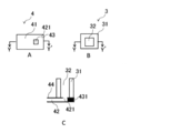
- 4A to 4C are diagrams showing an example of another embodiment of coupling the second unit 3 and the one end portion 43 of the third unit 4.
- 4A is a top view of the third unit 4 (view from the R1 direction of FIG. 3B)
- FIG. 4B is a top view of the second unit 3 (view from the R1 direction of FIG. 3C)
- FIG. 4C is the third unit.
- 4 is a schematic cross-sectional view (a view in the YY′ direction of FIGS. 4A and 4B) when the second unit 3 is stacked on the upper surface of FIG.
- the second culture tank 32 is formed so as to penetrate the second base material 31.
- the axon channel opening 421 is formed so as to penetrate the upper surface of the third base material 41 of the one end portion 43 of the third unit. Therefore, by connecting the second culture tank 32 of the second unit 3 and the axon flow path opening 421 so as to overlap with each other, the axon flow path 42 and the second culture tank 32 can be communicated with each other.
- the axon extending from the cell body of the motor neuron cultured in the second culture tank 32 passes through the axon flow path opening 421 and the other end portion 44 of the third unit. It is desirable to extend only to the side (on the side where the first unit 2 is arranged). Therefore, as shown in FIG. 4C, a flow channel may not be formed in a portion of the one end portion 43 of the third unit 4 in the side surface 431 direction from the axon flow channel opening 421. Further, as is clear from the above description, in the present specification, the “one end portion 43” of the third unit 4 means a portion which is inserted into the second unit 3 or overlaps with the second unit 3.
- the second substrate 31 and the second culture tank 32 are formed in a substantially rectangular parallelepiped shape, but the second culture is performed on the second substrate 31.
- the shapes of the second base material 31 and the second culture tank 32 are not particularly limited as long as the tank 32 is formed. Further, the production and material of the second unit 3 may be the same as those of the first unit 2.
- the third unit 4 includes a third base material 41 and an axon flow path 42.
- the third unit 4 includes one end portion 43 that is a portion that is inserted into the second unit 3 or that overlaps the second unit 3, and the other end portion 44 that is opposite to the one end portion 43 and that is disposed toward the first unit 2. Contains.
- a first opening 45 is formed in the other end portion 44 so as to contact the axon flow path 42.
- first axon passage holes 451 are formed in the first opening 45.
- the first axon passage hole 451 is not particularly limited as long as it is 1 or more, and may be appropriately determined in consideration of 2 or more, 3 or more, 4 or more, the size of the third unit 4, and the like.
- the first axon passage hole 451 is smaller than the cross-sectional area of the axon flow path 42 and has a size that allows at least one axon extending in the axon flow path 42 to pass therethrough. It only needs to be large enough to pass through.
- the “cross-sectional area” of the axon flow path 42 means a plane orthogonal to the direction in which the axon extends (direction toward the first opening 45, arrow direction in FIG. 5A).
- the size of the first axon passage hole 451 means the first opening surface 451a of the first axon passage hole 451 on the side of the axon flow path 42, or the second opening surface on the side opposite to the first opening surface 451a. It means 451b.
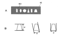
- FIG. 6A is a diagram showing the shape of the first opening surface 451a or the second opening surface 451b. Further, FIG. 6B is a diagram for explaining the sizes of the first opening surface 451a and the second opening surface 451b.
- the first axon passage hole 451 does not pass motor neurons and skeletal muscle cells, but needs to have a size that allows at least one axon to pass. There is no particular limitation on the shape or the like.
- the first axon passage hole 451 is, for example, a columnar structure such as a cylinder, an ellipse, a triangular prism, and a quadrangular prism, in other words, a tubular body in which the first opening surface 451a and the second opening surface 451b have the same shape and size. Is mentioned.
- the first axon passage hole 451 has at least one of the shape and size of a cone such as a cone, a triangular pyramid, and a quadrangular pyramid, in other words, the first opening surface 451a and the second opening surface 451b. It may be a different tubular body.
- the shapes of the first opening surface 451a and the second opening surface 451b are not particularly limited, such as a circle, an ellipse, and a polygon.
- the definition of the case where the “size” of the first opening surface 451a and the second opening surface 451b is described will be described with reference to FIG. 6B.
- the “size” is the diameter.
- the size is not uniquely determined. Therefore, as shown in FIG.
- the shortest distance d among the plurality of distances d obtained when the first opening surface 451a (second opening surface 451b) is sandwiched by parallel lines is referred to as “minimum distance.
- minimum distance the longest distance d among the plurality of distances d.
- the first opening surface 451a where the motor nerve cells may infiltrate needs to have a size that cannot pass through the motor nerve cells.
- the motor neuron is a non-spherical cell having a size of approximately 5 ⁇ m to 30 ⁇ m, although it varies depending on culture conditions and the like. In addition, motor neurons deform to some extent. Therefore, if the “minimum distance” of the first opening surface 451a is set to a size of, for example, less than 2.5 ⁇ m or 2.0 ⁇ m or less, the motor nerve cells are not deformed to be smaller than the “minimum distance”. .. Therefore, when the “minimum distance” is set to less than 2.5 ⁇ m, the “maximum distance” is not particularly limited.
- the “minimum distance” becomes a certain size, for example, 2.5 ⁇ m or more, whether or not the motor nerve cell passes is not limited to the “minimum distance” but the cross-sectional area of the first opening surface 451a (cross section). It is also necessary to consider the shape. For example, when the motor neurons do not pass when the cross-sectional area is 60 ⁇ m 2, the “maximum distance” is 24 ⁇ m or less when the “minimum distance” is 2.5 ⁇ m, and the “maximum distance” is when the “minimum distance” is 3 ⁇ m.
- the above-mentioned example of the cross-sectional area is a value obtained from the general size of motor neurons, and the cross-sectional area is not limited to 60 ⁇ m 2 .
- the cross-sectional area for example, 58 .mu.m 2 or less, 56 .mu.m 2 or less, 54 .mu.m 2 or less, 52 .mu.m 2 or less, 50 [mu] m 2 or less or the like, may be appropriately changed.
- the second opening surface 451b in which skeletal muscle cells may infiltrate needs to have a size that does not allow passage of skeletal muscle cells.
- the size of the skeletal muscle cells is approximately 5 ⁇ m to 30 ⁇ m, like the motor neurons. Therefore, the size of the second opening surface 451b may be adjusted so as to have the same “minimum distance” or “cross-sectional area” as that of the first opening surface 451a.
- the “minimum distance” between the first opening surface 451a and the second opening surface 451b can be 0.5 ⁇ m or more, 1 ⁇ m or more, 1.5 ⁇ m or more, 2 ⁇ m or more.
- the length of the first axon passage hole 451 is not particularly limited from the viewpoint of passage of the axon.
- the length may be appropriately determined from the viewpoints of manufacturing convenience, handling convenience, and the like.
- the lower limit may be, for example, 1 ⁇ m or more, 50 ⁇ m or more, 100 ⁇ m or more.
- the upper limit can be, for example, 1000 ⁇ m or less, 750 ⁇ m or less, and 500 ⁇ m or less.
- the circumference of the axon flow path 42 is covered with the third base material 41 (in the case of the example shown in FIG. 4, there may be a part that is not covered), and the other end portion 44 has the first opening portion.
- the shape and size are not particularly limited as long as 45 is formed and one end portion 43 can communicate with the second culture tank 32.
- the cross-sectional shape may be a substantially rectangular parallelepiped, a polygonal shape, or a circular shape.
- the width of the axon flow path 42 (the length in the direction substantially orthogonal to the line connecting the one end portion 43 and the other end portion 44) is not particularly limited.
- the width of the axon flow path 42 is from 10 ⁇ m to
- the thickness can be 1000 ⁇ m, 100 ⁇ m to 750 ⁇ m, 250 ⁇ m to 500 ⁇ m.
- the height of the axon channel 42 (the length in the vertical direction in FIG. 3B) can be 10 ⁇ m to 200 ⁇ m, 30 ⁇ m to 100 ⁇ m, and 50 ⁇ m to 75 ⁇ m.
- both the width and height of the axon channel 42 are made sufficiently larger than the motor nerve cells, the motor neurons may enter the axon channel 42.
- a slit for preventing the passage of motor neurons may be provided in the portion where the second culture tank 32 and the axon channel 42 are joined, or in the axon channel 42. More specifically, for example, as shown in FIG. 4C, when the second unit 3 is overlaid on the third unit 4, if the size of the axon channel opening 421 is set to a size through which motor neurons cannot pass. Good.
- FIG. 4C when the second unit 3 is overlaid on the third unit 4, if the size of the axon channel opening 421 is set to a size through which motor neurons cannot pass. Good.
- the size of the axon channel opening 421 is adjusted, but alternatively, a hole is formed in the bottom portion of the second culture tank 32, and the size is adjusted by the size of the hole. May be.
- a slit 423 having a size that does not allow motor neurons to pass may be formed at a position separated from the first opening 45 of the axon channel 42.
- the first axon passage holes 451 are arranged in a horizontal row, but as shown in FIG. 5C, the first axon passage holes 451 may be arranged in two rows. Alternatively, although not shown, the first axon passage holes 451 may be arranged in three or more rows.
- the first opening 45 and the axon flow path 42 are shown as being manufactured separately, but the first opening 45 and the axon flow path 42 are integrated. It may be prepared as desired. The production and material of the third unit may be the same as those of the first unit 2.
- the device 1a according to the first embodiment may be provided in a state in which the first to third units are separated or in a combined state. Further, when the pillar 23 is provided on the lid 6, the lid 6 may be provided in a separated state.
- FIG. 3D shows an example of the positional relationship when the first to third units are combined.
- the axon extending from the first axon passage hole 451 of the first opening 45 of the third unit 4 into the first culture tank 22 is a skeleton formed between the pillars 23 (for example, between the other ends 232). Reach muscle tissue and create a neuromuscular junction. Therefore, it is desirable that the third unit 4 is arranged so that the axon can easily reach the skeletal muscle tissue. In the example shown in FIG.
- a virtual axon flow path 42a obtained by virtually extending the axon flow path 42 into the first culture tank 22 is an extension line connecting the other ends 232 of two or more pillars 23 (or, It is arranged so as to intersect with any one of (a virtual surface connecting two or more pillars 23).
- the skeletal muscle tissue is organized so that the pillars 23 are connected to each other by using the pillars 23 as scaffolds. Therefore, by arranging the other end portion 44 of the third unit 4 and the first unit 2 as described above, it becomes easy to form the neuromuscular junction. Further, as shown in FIGS.
- the third device 4 is connected in a direction substantially orthogonal to the gravity direction of the second culture tank 32. Therefore, in order to intersect the virtually extended virtual axon channel 42a in the direction of the skeletal muscle tissue formed in a state of floating in the medium described later, the first unit 2 is provided with the second unit 3. It is preferable to form a notch 24 for placement.
- the bottom surface of the second device 3 is Even if it is placed on the upper surface portion of the first substrate 21 of the one device 2, the virtually extended virtual axon channel 42a can be arranged so as to intersect with any one of the virtual surfaces formed by the two or more pillars 23. .. Therefore, the notch 24 may be formed as needed.
- FIGS. 7A and 7B are schematic cross-sectional views (same direction as FIG. 5A) of the device 1b of the second embodiment
- FIG. 7B is a bb′ cross-sectional view of FIG. 7A.
- the device 1b according to the second embodiment is different from the device 1a according to the first embodiment in that a channel is further formed inside the axon channel 42 of the third unit 4, but other points. Is the same as the device 1a according to the first embodiment. Therefore, in the second embodiment, points different from the first embodiment will be mainly described, and repetitive description of the items already described in the first embodiment will be omitted. Therefore, it is needless to say that the items described in the first embodiment can be adopted in the second embodiment even if they are not explicitly described in the second embodiment.
- the axon flow channel 42 shown in FIG. 7A includes a first flow channel 42b and a second flow channel 42c formed inside the first flow channel 42b.
- the first opening 45 is formed so as to be in contact with the first flow path 42b.
- One end 42c1 of the second flow channel 42c communicates with the second culture tank 32, and the other end 42c2 of the second flow channel 42c is formed so that the second opening 45a is in contact therewith.
- One or more second axon passage holes 451' are formed in the second opening 45a.
- the second axon passage hole 451 ′ has a size that allows the axon to pass though it cannot pass the motor neuron and the skeletal muscle cell. Further, the first opening 45 and the second opening 45a are arranged apart from each other.
- the axon extending from the cell body of the motor neuron cultured in the second culture tank 32 passes through the second opening 45a, then the first flow path 42b, and further the first opening 45.
- the first flow path 42b To form a neuromuscular junction with skeletal muscle tissue.
- one end 42b1 and the other end 42b2 of the first flow path 42b are not in communication with the second culture tank 32. Therefore, since motor neurons and skeletal muscle cells do not infiltrate into the first flow path 42b, by flowing a culture medium containing a test substance of a therapeutic agent for neuromuscular disease into the first flow path 42b, only axons Can be selectively stimulated.
- the "second axon passage hole 451'" is the “first axon passage hole 451”
- the "first opening surface 451a'” is the “first opening surface 451”
- “451b'” may be read as “second opening surface 451b”.
- the second opening 45a is smaller in size than the first opening 45, but the axon passage hole, the first opening surface, and the second opening 45a formed in the first opening 45 and the second opening 45a are formed.
- the shape and size of the opening surface may be the same.
- the first opening portion 45 and the second opening portion 45a may be different.
- the device 1b according to the second embodiment is made of the same material as that of the third base material 41, and the second unit is provided inside the first flow path 42b.
- the flow path wall surface 42c3 may be formed.
- the fabrication and material of the third unit 4 of the device 1b according to the second embodiment may be the same as those of the third unit 4 of the device 1a according to the first embodiment.
- FIGS. 8A and 8B are schematic top views of the device 1c according to the third embodiment.
- a device 5 for culturing a motor neuron is produced by connecting the second unit 3 and the third unit 4, and two or more devices are prepared for one first unit 2.
- the device 5 for culturing motor neurons is different from the device 1a according to the first embodiment and the device 1b according to the second embodiment in that the device 5 for culturing motor neurons is arranged, but other points are the device 1a according to the first embodiment. And the same as the device 1b according to the second embodiment.
- FIG. 8A shows that two motor neuron cell culture devices 5 are arranged in the same skeletal muscle tissue formed between two pillars 23, and axons extending from each motor neuron cell culture device 5 are arranged.
- 11 shows an example in which the neuromuscular junction is formed by 11 and the skeletal muscle tissue 10.
- two axons 11 are connected to the same skeletal muscle tissue. Therefore, when screening therapeutic agents for neuromuscular diseases, it is possible to observe the effects of changing the type of test substance to be put into each motor neuron cell culture device 5 or changing the concentration of the same type. it can.
- FIG. 8A shows that two motor neuron cell culture devices 5 are arranged in the same skeletal muscle tissue formed between two pillars 23, and axons extending from each motor neuron cell culture device 5 are arranged.
- 11 shows an example in which the neuromuscular junction is formed by 11 and the skeletal muscle tissue 10.
- two axons 11 are connected to the same skeletal muscle tissue. Therefore, when screening therapeutic agents for neuromuscular diseases,
- two motor neuron cell culture devices 5 are arranged, but the axon 11 extending from the motor neuron cell culture device 5 has skeletal muscle tissue 10 and nerve muscles. If the junction can be formed, the number of the motor neuron cell culture devices 5 to be arranged may be three or more.
- FIG. 8B two motoneuron cell culture devices 5 are arranged for the skeletal muscle tissues formed between the three pillars 23, and axes extending from the respective motoneuron cell culture devices 5 are arranged.
- An example is shown in which the cord 11 and the skeletal muscle tissue 10 form a neuromuscular junction.
- the example shown in FIG. 8B can simultaneously screen a plurality of test substances.
- three or more motor neuron cell culture devices 5 may be arranged for one skeletal muscle tissue 10.
- the example shown in FIG. 8B for example, when one skeletal muscle tissue 10 is stimulated and contracted, the other skeletal muscle tissue 10 can be stretched. Since the muscles move in pairs in the living body, the example shown in FIG. 8B can reproduce a phenomenon closer to the living body.
- FIG. 9A is a schematic top view of the device 1d according to the fourth embodiment.
- a motor neuron culture device 5a is produced by connecting two or more third units 4 to one second unit 3, and the second unit 3 has a second unit 3 at the other end.
- 1 unit 2 is arranged, which is different from the device 1a according to the first embodiment and the device 1b according to the second embodiment, but the other points are different from the device 1a according to the first embodiment and the device 1a according to the second embodiment. It is the same as the device 1b according to the embodiment.
- the device 1d according to the fourth embodiment can form a neuromuscular junction by joining axons 11 extending from the cell bodies of motor neurons cultured in one second unit 3 to different skeletal muscle tissues 10. .. Even when the first unit 2 and the second unit 3 are provided one by one, it is of course possible to prepare an evaluation model and screen a test substance as a therapeutic agent for neuromuscular disease. However, for example, when the formation of skeletal muscle tissue from skeletal muscle cells is insufficient or the formation of the neuromuscular junction is insufficient, even a useful test substance can be used during screening. May be overlooked.
- the axon 11 extending from the mass of motor neurons cultured in the second culture tank 32 can form a neuromuscular junction with different skeletal muscle tissues. Therefore, for example, when screening a test substance for a therapeutic agent for a neuromuscular disease that stimulates motor neurons, it is possible to confirm whether the skeletal muscle tissue 10 moves in the same manner. The accuracy of can be improved.
- the above-described first to fourth embodiments are examples of the device 1 disclosed in the present specification, and the present invention is not limited to the above embodiments. It is possible to freely combine the above-described embodiments, modify any constituent element of each embodiment, or omit any constituent element.
- the third unit 4 has a single-layer structure in which the third base material 41 covers the periphery of the axon flow path 42, but by stacking the third unit 4, It may have a multilayer structure.
- the axon extending from the first opening 45 to the skeletal muscle tissue 10 has a three-dimensional structure, which facilitates formation of the neuromuscular junction.
- the device 5 for culturing motor neurons has already been described in the third and fourth embodiments of the device 1. Therefore, the description will be duplicated, and the description of the device 5 for culturing motor neurons will be omitted.
- the second unit 3 and the third unit 4 may be integrated, or the second unit 3 and the third unit 4 may be combined.
- the device 5 for culturing motor neurons may be produced by using parts common to the unit 4 and combining the parts. For example, a part of the second base material 31 and the third base material 41 may be configured by one part.
- the motor neuron cell culture device 5 is combined with the first unit 2 to fabricate the coculture device 1
- the third unit 4 includes the first flow channel 42b and the second flow channel 42c formed inside the first flow channel 42b shown in FIG. 7A
- the device 5 for culturing motor neurons is , May be used alone as a model device for reproducing axon tear and regeneration.
- a pathological condition called neuropathy is known in which normal conduction of peripheral nerves is impaired.
- axonal degenerative neuropathy due to traumatic or local axotomy is known.
- shear stress is applied to the axon between the second opening 45a of the second channel 42c and the first opening 45 of the first channel 42b of the device 5 for culturing motor neurons. It can be expected to be applied to the axonal degenerative neuropathy model by rupturing due to such factors as, and then regenerating. Note that, of course, the model for reproducing the tearing and regeneration of the axon may be prepared using the coculture device 1.
- the multi-well plate 500 will be described with reference to FIG. 9B.
- 9B(a) is a top view showing the outline of the multi-well plate 500
- FIG. 9B(b) is a sectional view taken along line XX′ of FIG. 9B(a).
- the multi-well plate 500 has a base material 501 and at least two wells 502 formed in the base material 501. Then, in at least one of the wells 502, the device 1 described in the first to fourth embodiments and the device selected from the device 5 for culturing motor neurons are arranged.
- a pair of electrodes 503 may be formed in any well 502 as necessary.
- a circuit 504 for connecting the pair of electrodes 503 and a power supply device may be formed on the base material 501.
- the multi-well plate 500 is not particularly limited in the number and shape of the wells 502 as long as the devices 1 and 5 can be arranged in the wells 502.
- the well 502 is formed in the substrate 501 in a substantially columnar shape, but may have a hemispherical shape or a substantially polygonal pillar shape, for example.
- the devices 1 and 5 arranged in the well 502 may all be of the same type, or may be arranged by combining different types. Further, the devices 1 and 5 may be arranged in a part of the well 502, or the devices may be arranged in all the wells 502. The devices 1 and 5 may be arranged so as to be attachable to and detachable from the well 502, in other words, may be only inserted into the well 502, or may be disposed so as not to be detachable. In the case where the devices 1 and 5 are arranged so as not to be detachable, the devices 1 and 5 may be fixed to the wall surface of the well 502 using an adhesive or the like.
- the devices 1 and 5 By arranging the devices 1 and 5 in the well, the following effects are synergistically exhibited. (1) When the medium is introduced into the first medium introduction hole 221 or the second medium introduction hole 321, the medium remains in the well 502 even when the medium overflows from the first culture tank or the second culture tank. The convenience of adding the medium is improved. (2) By arranging the devices 1 and 5 on a Mullwell plate, it is possible to assay or screen a plurality of drugs at the same time, and it is possible to achieve high throughput. In the example shown in FIG. 9B, since the devices 1 and 5 are arranged in the well 502, the effect of (1) above and high throughput of drug assay and the like can be achieved at the same time.
- the devices 1 and 5 may be arranged not on a multiwell plate but on a plate-like member having no wells such as a glass substrate and used. Good. (3) Further, when a pair of electrodes 503 is arranged in the well 502, it is possible to apply electrical stimulation to the produced evaluation model. In the example shown in FIG. 9B, the pair of electrodes 503 is provided in the well 502, but alternatively, the pair of electrodes may be provided on the inner wall surface of the culture tank of the devices 1 and 5 or the like. ..
- a pair of electrodes is inserted into the well 502 of the well plate 500, the culture tank of the device 1 or 5, or the like, so that the evaluation model is electrically stimulated. May be given.
- FIG. 10 is a flowchart of an embodiment of a method for producing an evaluation model.
- the embodiment of the method for producing the evaluation model includes a motor neuron cell culture step (ST1), a skeletal muscle tissue preparation step (ST2), and a neuromuscular junction preparation step (ST3).
- motor neurons are cultured in the second culture tank 32 of the second unit 3.
- the motor neuron is not particularly limited as long as it can grow the axon 11 by culturing.
- the motor nerve cells described in Non-Patent Document 1 and Non-Patent Document 2 can be used.
- the motor neurons the dissociated motor neurons may be cultured in the second culture tank 32, or spheroids in which the motor neurons are agglomerated may be used.
- the medium for culturing the motor neurons may be appropriately selected depending on the motor neurons used.
- skeletal muscle cells are cultured in the first culture tank 22 of the first unit 2 to produce skeletal muscle tissue.
- the skeletal muscle cells are not particularly limited as long as they can form the skeletal muscle tissue 10 between the pillars 23 by culturing.
- the skeletal muscle cells for example, the skeletal muscle cells described in Non-Patent Document 1 and Non-Patent Document 2 may be used.
- the medium for culturing skeletal muscle cells may be appropriately selected according to the skeletal muscle cells used.
- the order of the step of culturing motor neurons (ST1) and the step of preparing skeletal muscle tissue (ST2) may be reversed or may be performed simultaneously.
- the axon 11 extending from the cell body of the cultured motor neuron passes through the axon channel 42 of the third unit 4 and is produced in the first culture tank 22.
- a neuromuscular junction is created by joining with tissue.
- the skeletal muscle tissue is floating in the medium, and the skeletal muscle tissue and the cell body of the motor nerve cell are separated, so that both can be joined by the axon 11, so that the evaluation is closer to the actual human body.
- a model can be created.
- the device 1 disclosed in the present specification uses a medium for culturing motor neurons and skeletal muscle cells. Therefore, the axon flow path 42 of the third device 4 and the first axon passage hole 451 (second axon passage hole 451′) smaller than the axon flow path 42 can permeate the medium with a capillary force. it can.
- the device described in Non-Patent Document 2 (method for producing an evaluation model) uses collagen gel as a scaffold for extending axons, but collagen gel has viscosity. Therefore, in the invention described in Non-Patent Document 2, if the channel through which the axon extends is simply thinned, the collagen gel containing the medium cannot penetrate into the channel.
- the device 1 disclosed in the present specification and the method for producing an evaluation model using the device 1 include the axon channel 42 and the first axon passage hole 451 (the second axon passage hole) as a scaffold on which the axon 11 extends. 451'), and further based on a new finding combining a medium that permeates the scaffold.
- the evaluation model produced by the device 1 disclosed in the present specification exhibits the following combined effects in addition to the effect of making it easy to observe the movement of skeletal muscle tissue by not using collagen as a scaffold.
- a scaffold is formed from collagen gel
- the drug needs to penetrate into the collagen gel in order to stimulate the motor nerve cells, axon, and skeletal muscle tissue with the drug. Therefore, rapid screening of drugs is not possible.
- the drug diffuses when penetrating into the collagen gel, which makes it difficult to perform screening that specifies targets of motor neurons, axons extending from cell bodies of motor neurons, and skeletal muscle tissue.
- the motor nerve cells, the skeletal muscle tissue, and the axons extending from the cell bodies of the motor nerve cells are separated. Therefore, targeted drug screening can be performed.
- axons extending from the cell bodies of motor neurons, skeletal muscle tissue, and motor neurons are formed in the medium, respectively, the drug can be rapidly screened.
- collagen gel is a gel derived from a living body, the characteristics differ from lot to lot.
- the characteristics of the gel change when the conditions such as the temperature change, the variation among the manufactured evaluation models increases.
- the evaluation model manufactured by the device 1 disclosed in the present specification uses the medium, the fluctuation of the manufactured evaluation model can be reduced.
- Non-Patent Document 2 the entire device 1 is covered with collagen gel. Therefore, for example, even if an attempt is made to investigate the effect on the motor nerve cells when electrical stimulation is applied to skeletal muscle tissue, electricity leaks through the collagen gel and it is difficult to apply selective electrical stimulation.
- the skeletal muscle tissue and the motor neuron communicate with each other through only the first axon passage hole 451 (second axon passage hole 451′). There is. Therefore, selective electrical stimulation of skeletal muscle tissue and motor neurons is possible.
- Non-Patent Document 2 since the axons extend in random directions in the collagen gel and reach the skeletal muscle tissue, the axons toward the skeletal muscle tissue cannot be adjusted.
- the evaluation model produced by the device 1 disclosed in the present specification since the axon needs to pass through the first axon passage hole 451, the number and intervals of the axons extending to the skeletal muscle tissue can be adjusted. .. Therefore, variations in the produced evaluation model can be reduced.
- an evaluation model is produced using the device 1 including the third unit 4 having the first flow channel 42b and the second flow channel 42c. Then, a step of rupturing the axon between the second opening 45a of the second flow path 42c and the first opening 45 of the first flow path 42b and then regenerating the axon may be added.
- the skeletal muscle tissue producing step (ST2) and the neuromuscular junction producing step (ST3) may be omitted.
- the bone motor neuron cell culture step ( After performing ST1), the step of rupturing the axon between the second opening 45a of the second flow path 42c and the first opening 45 of the first flow path 42b, and then regenerating the axon may be added. Good.
- FIG. 11 is a flowchart of an embodiment of the screening method.
- the embodiment of the screening method includes a test substance administration step (ST11), an observation step (ST12), and a test substance evaluation step (ST13).
- the test substance is administered to any one of motor neurons, axons extending from the cell body of the motor neurons of the evaluation model thus prepared, and skeletal muscle tissue.
- the test substance is not particularly limited as long as it is a substance known as a drug such as a low molecular weight compound, a nucleic acid, an antibody and a protein.
- the test substance may be administered to the second culture tank.
- it may be dissolved in a medium and administered as necessary.
- a test substance may be administered to the axons.
- the test substance When the test substance is administered to the axon, the test substance may be passed through the first channel 42b of the third unit 4 shown in the second embodiment. Alternatively, when the length of the axon is relatively long, the test substance may be administered to the axon near the first opening 45 of the third unit 4 shown in the first embodiment. Alternatively, for example, a through hole penetrating the axon channel 42 may be formed in the third base material 41 of the third unit 4 shown in FIG. 3B, and the test substance may be administered into the axon channel 42.
- the measurement step (ST12) at least one state of motor nerve cells, axons extending from the cell body of the motor nerve cells, and skeletal muscle tissue after the test substance is administered in the test substance administration step is measured.
- the measuring step is not particularly limited as long as it can measure changes in the state of motor neurons, axons extending from the cell bodies of motor neurons, and skeletal muscle tissue before and after administration of the test substance.
- the state of the skeletal muscle tissue 10 the movement of the skeletal muscle tissue 10 may be measured.
- the movement of the skeletal muscle tissue may be measured directly or indirectly.
- a direct measuring method an example of observing the motion of the skeletal muscle tissue 10 with a moving image using an image sensor is given.
- a load is applied to the pillar 23. Therefore, as an indirect measurement method, an example in which a strain sensor is arranged inside or on the surface of the pillar 23 and the force related to the strain sensor is measured can be given.
- the measurement of the state of axons includes, for example, the increase/decrease in the number of axons due to the influence of the test substance, the change in elongation, the cutting and regeneration status of axons, etc.
- Examples of the measurement method include measurement using an image sensor.
- the measurement of the state of the motor neuron includes, for example, the death or growth of the motor neuron due to the influence of the test substance and the change in the shape of the mass (spheroid) of the motor neuron due to the death or growth.
- Examples of the measurement method include measurement using an image sensor.
- test substance evaluation step (ST13) it is evaluated from the measurement result of the measurement step (ST12) whether the test substance acts as a therapeutic agent for neuromuscular disease.
- a human may evaluate the measurement result, or the movement of the skeletal muscle tissue of the human body when the therapeutic agent is administered is stored in the memory means in advance, and the movement similar to that when the therapeutic agent is administered is performed.
- the test substance may be evaluated as having a therapeutic effect.
- the neuromuscular disease is not particularly limited as long as it is a disease relating to signal transduction between motor neurons and skeletal muscle tissue.
- hereditary diseases caused by gene mutations such as amyotrophic lateral sclerosis (ALS) and bulbar and spinal muscular atrophy (SBMA) can be mentioned.
- Other than genetic diseases for example, brachial plexus damage, facial nerve palsy, and other diseases caused by axon extending from the cell body of motor neurons by physical shock or neurotoxic substances are mentioned. ..
- a template for preparing a device was prepared by the following procedure.
- Photolithography of the template was performed using laser lithography.
- the device used was Heidelberg DWL66FS (Heidelberg Instruments, Heidelberg, Germany).
- CS HARDMASK BLANKS CBL3006Cu-AZP, CLEAN SURFACE TECHNOLOGY, Kanagawa, Japan
- This photomask has a layer of chromium on a glass plate, and a photosensitive material AZP1350 is applied thereon.
- a laser designed pattern was drawn on a photomask and developed with NMD3.
- a mold was prepared using the prepared photomask.
- a mask aligner MA-6 (Suss Micro Tec AG) was used.
- SU-8 3005 (Nippon Kayaku Co., Ltd., Tokyo, Japan.
- SU-8 3005 to the extent that 80% of the whole is hidden in a silicon wafer (Polishing Wafer (4PTP-1-100, Global Wafers, Hsinchu, Taiwan)).
- Is cyclopentanone (C0510, Tokyo Kasei Kogyo Co., Ltd., Tokyo, Japan), and the spin speed is increased to 500 rpm at 100 rpm/sec for 30 seconds.
- the number of rotations was increased to 3000 rpm at 300 rpm/sec and spin coating was performed for 30 seconds. After that, heating was performed at 95° C.
- the photomask on which the completed silicon wafer and flow path pattern were provided was set on MA-6, and exposed to ultraviolet rays for 40 seconds.
- the exposure hardens the SU-8 into the same shape as the pattern on the photomask.
- it was heated at 65° C. for 1 minute 50 seconds and at 95° C. for 20 seconds (Postbake).
- SU-8 3050 Nippon Kayaku Co., Ltd., Tokyo, Japan was placed on the silicon wafer until 80% of the whole was hidden, and the speed was increased to 2000 rpm at 100 rpm/sec and spin-coated for 30 seconds. It was Then, it was heated at 95° C.
- FIGS. 12A and 12B The produced mold is shown in FIGS. 12A and 12B.
- FIG. 12A is a mold corresponding to the axon flow channel of the first embodiment, and FIG.
- FIG. 12B is a mold corresponding to the axon flow channel (first flow channel+second flow channel) of the second embodiment.
- a device manufactured using the mold shown in FIG. 12A may be described as “device a”
- a device manufactured using the mold illustrated in FIG. 12B may be described as “device b”.
- the surfaces to be bonded are plasma-treated so that the PDMSs can be bonded to each other.
- PLASMA CLEANER PDC-32G, HARRICK PLASMA, New York, USA was used for the plasma treatment.
- FIG. 13 is a photograph of the prepared motor neuron cell culture devices a and b.
- the arrow portions of the device for culturing nerve cells b are a test substance input hole and a test substance recovery hole which are formed in the second base material 31 and communicate with the first flow path 42b.
- PDMS was poured into a mold (see FIG. 14) and heated at 70° C. for 1 hour to solidify PDMS. After removing from the mold, a disk made of thin film PDMS was placed on the pillar of the first unit. The thin film disk was prepared by placing 0.2 g of PDMS on a Teflon sheet, increasing the rotation speed to 1000 rpm in 30 seconds, and spin-coating for 30 seconds. Then, PDMS was solidified by heating at 70° C. for 1 hour. Further, 0.2 g of PDMS was placed, the rotation speed was increased to 2000 rpm in 30 seconds, and spin coating was performed for 30 seconds.
- a circle with a diameter of 1.5 mm is cut out from this thin film of PDMS with a biopsy (8-5845-02, kai industries, Japan), attached to the upper part of the pillar of the first unit, and heated at 70°C for 1 hour to the tip of the pillar.
- the thin film disc was fixed.
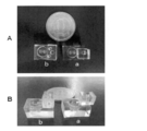
- FIG. 15 is a photograph of the manufactured devices a and b.
- FIG. 15A is a photograph from above of the manufactured devices a and b
- FIG. 15B is a photograph from above of the manufactured devices a and b.
- Example 2 [Production of evaluation model] An evaluation model was prepared using the materials and methods described below.
- Laminin coating was performed by adding 3 ml of PBS, adding 25 ⁇ l of iMatrix-511 (381-07363, Wako, Tokyo, Japan) thereto, and incubating for 1 hour or more in a CO 2 incubator.
- iMatrix-511 381-07363, Wako, Tokyo, Japan
- AK02N 2.5 ml of AK02N was added in a state where the iMatrix solution was contained to make the mixture acclimatize, and then the solution was removed, and 5 ml of AK02N was added.
- 5 ⁇ l of ROCK inhibitor Y-27632 (08945-71, Nacalai Tesque, Inc., Kyoto, Japan) was added and incubated in a CO 2 incubator until just before seeding.
- TrypLE registered trademark
- Select CTS registered trademark
- UltraPure registered trademark 0 1 M trypsin solution prepared by mixing 1:5 M EDTA pH 8.0 (15575-038, Life Technologies, Calif., USA) was added, and the mixture was incubated in a CO 2 incubator for 4 minutes.
- the trypsin solution was removed, and the cells were washed once with PBS, 2.5 ml of AK02N was added, and the cells were collected with a cell scraper (9902, TPP, Switzerland).
- the collected cells were suspended 10 times with 1 ml Pipetman, and then the number of cells was calculated with a TC20 (registered trademark) fully automatic cell counter (California, USA). Then, the T25 flask was inoculated so as to have 32500 cells and incubated in a CO 2 incubator. The medium was changed 24 hours after seeding to remove Y-27632. Thereafter, the medium was replaced every 48 hours, and when the cells approached confluence, the medium was replaced every 24 hours.
- the growth medium was DMEM (20% Fetal Bovine Serum, 2 mM L-glutamine (073-05391, Wako, Tokyo, Japan), 0.5% penicillin/streptomycin, 2% Ultroser G serum New, 15P9, 10% substrate). City, USA) was used.
- FIG. 17 is a diagram showing the procedure of co-culture.
- the device prepared in Example 1 was fixed to the bottom of the well of a 12-well plate for convenience of experiments such as medium exchange. After fixing the device and the well, UV sterilization was performed for 1 hour. After that, plasma treatment (11 W, 30 sec) was performed to perform matrigel coating. Matrigel (354234, CORNING, New York City, USA) was added to serum-free DMEM/F-12 (Dulbecco's Modified Eagle Medium: Nutrient Mixture F-12) (042-30555, Wako, Jako, Tokyo).
- DMEM/F-12 Dulbecco's Modified Eagle Medium: Nutrient Mixture F-12
- the device Diluted and placed in the device.
- the bottom surface of the device was completely filled with the Matrigel solution and allowed to stand at room temperature for 3 hours.
- the matrigel solution was allowed to stand while being deaerated so that the Matrigel solution could be spread over the entire channel.
- all Matrigel solutions were pulled out with an aspirator.
- the protein contained in Matrigel is adsorbed to the second culture tank 32 and the axon channel 42, so that the motor neurons are easily adsorbed to the second culture tank 32 and the axons are easily adsorbed to the axon channel 42. ..
- MN medium motor nerve medium containing the following medium additives was used in KBM Neural Stem Cell Kit (16050100, Kohjin bio, Saitama, Japan).
- Media additives are 2% B-27 (17504-044, Thermofisher, Massachusetts, USA), 1% non-essential amino acids; NEAA (11140050, Lifetechnologies, California, USA, 60 g, USA), 1 ⁇ M-DAMc, USA, 1 ⁇ M.
- human skeletal muscle cells Hu5KD3 were seeded in the first culture tank. Specifically, cells cultured in a T-75 flask were collected in the same manner as in the passage procedure, the cell number was measured, and fibrinogen (F8630, Sigma-Aldrich, Missouri, USA), Matrigel, Thrombin from bovine plasma were collected. (Thrombin: T4648, Sigma-Aldrich, Missouri, USA) A solution containing 2 ⁇ DMEM was seeded in the first culture tank at 2 ⁇ 10 6 cells/ml. The composition of the final solution is shown in Table 2. Tissue formation/proliferation/differentiation was performed by adding 3 ml of MN medium so as to fill the entire well containing the device.
- 6-Amino caproic Acid (A2504, Sigma-Aldrich, Missouri, USA) (6AA) was added at 2.0 mg/ml in order to prevent the degradation of muscle tissue.
- the matrigel bonding is an auxiliary procedure and may be omitted.
- the medium was exchanged once every two days with a half volume change. An evaluation model was produced by the above procedure.
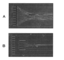
- FIG. 18A is an enlarged photograph near the first opening of the third unit of the evaluation model manufactured using device a.
- FIG. 18B is an enlarged photograph near the first opening of the third unit of the evaluation model manufactured using the device b.
- the evaluation model produced using the device a and the device b shows that the axon extends in the axon channel and that the axon passes through the first axon passage hole (second axon passage hole). confirmed.
- Triton X-100 T8787-250 ml, Sigma Aldrich, Missouri, USA
- PBS 0.3% Triton X-100 (T8787-250 ml, Sigma Aldrich, Missouri, USA)/PBS was added, and the membrane was allowed to pass through the membrane for 5 minutes at room temperature.
- blocking was performed by washing three times with PBS, adding the primary antibody/basic solution, and leaving it to stand for 1 hour.
- the composition of the basic solution was 10% Goat serum (S-1000, Vector Laboratories, Calif., USA)+0.01% Triton X-100/PBS.
- a basic solution prepared by mixing the primary antibody so as to have a concentration of 2 ⁇ g/ml was added and reacted at 4° C. overnight.
- the primary antibody used for immunostaining of myotubes is TUJ1 (845501, Biolegend, USA).
- the solution was withdrawn, washed 3 times with PBS, and a basic solution containing a secondary antibody at a concentration of 4 ⁇ g/ml was added and reacted for 1 hour.
- the secondary antibody used was CF543 (registered trademark) Goat anti-rabbit IgG (H+L), Highly Vross-adsorbed, 2 mg/ml (20300, BIOTIUM, California, USA).
- Fluoredcein-alpha-bungarotoxin (PK-CA707-00011, PromoKine, Heidelberg, Germany), which is a fluorescent dye of ⁇ -bungarotoxin, which is an antagonist, is used at a final concentration of 4 ⁇ g/ml.
- the cells were washed 3 times with PBS and observed with a confocal microscope.
- FIG. 19 is a photograph taken with a confocal microscope, and the stained portion at the tip of the triangle in the figure shows that the aggregation of acetylcholine receptors was stained. Acetylcholine receptors are aggregated at the neuromuscular junction. Since staining of acetylcholine receptor aggregation was confirmed in the produced evaluation model, it was confirmed that a neuromuscular junction was formed in the produced evaluation model.
- tetrodotoxin (TTX, 206-11071, Wako, Tokyo, Japan) is adjusted to a final concentration of 2 ⁇ M after about 20 seconds.
- Tetrodotoxin selectively blocks Na channels in motor excitable membranes.
- a moving image was photographed using BZ-X710, and the state of contraction was graphed using the moving image analysis software PV Studio 2D (OA Science, Miyazaki, Japan).
- FIG. 20 is a graph showing contraction of skeletal muscle tissue before and after drug addition.
- skeletal muscle tissue contracted by administering glutamic acid to the second culture vessel, that is, to the motor neurons.
- the administration of tetrodotoxin stops the contraction of skeletal muscle tissue.
- the evaluation model produced using the device disclosed in the present specification indicates that the axon extending from the cell body of the motor neuron is joined to the skeletal muscle tissue to form the neuromuscular junction. It was confirmed.
- the therapeutic model for neuromuscular disease can be screened by using the evaluation model disclosed in this specification.
- 21A and 21B are photographs observed with a microscope, in which the brightness is changed at the same place.
- the bright part at the tip of the arrow in the photograph is the stained axon. It was confirmed that by introducing the staining reagent into the first channel, only the axon in the first channel can be selectively stained. Therefore, it was confirmed that if a test substance for a therapeutic drug for neuromuscular disease is used instead of the staining reagent, it can be used for screening for a therapeutic drug that specifically affects axons.
- the evaluation model prepared by co-culturing the motor neurons and the skeletal muscle cells using the device prepared in Example 1 was used until another experiment on the 27th day until the motor neurons and the skeletal muscle cells were used. No fusion was seen.
- the evaluation model produced using the device described in Non-Patent Document 2 shows that 14 days after the start of co-culture, the motor nerve cells crossed the pillar. Therefore, when an evaluation model is manufactured using a device disclosed in this specification, an axis extending from a motor neuron or a cell body of a motor neuron for a long period of time is compared with an evaluation model manufactured using a conventional device. It can be evaluated with the cord and skeletal muscle tissue separated.
- Example 3> [Confirmation of axonal rupture and regeneration]
- motor neurons were cultured in the same procedure as in (1) of ⁇ Example 2> above.
- a syringe pump was used to flow the medium into the first flow passage 42b from one end 42b1 of the first flow passage 42b with a shear stress of about 60 Pa.
- 22A to 22C are enlarged photographs of the vicinity of the second opening 45a of the third unit 4 after completion of the culture.
- FIG. 22A is a photograph at the end of the culture of motor neurons, and confirmed axons (arrows in FIG.
- FIG. 22A is a photograph after a lapse of about 30 seconds after flowing the medium with a shear stress of about 60 Pa, and confirmed that the axons were ruptured.
- FIG. 22C is a photograph about 24 hours after the axonal rupture, and it was confirmed that the axons were regenerated (arrow in FIG. 22C). From the above results, it was confirmed that axon rupture and regeneration can be performed by using the device disclosed in the present application.
- the evaluation model produced using the device, and the screening method using the evaluation model a therapeutic drug for neuromuscular disease can be screened. Therefore, it is useful for drug discovery in medical institutions, universities, companies, research institutions and the like.
- Second axon passage hole 451a, 451'a... First opening surface, 451b, 451'b... Second opening surface, 500... Multi-well plate, 501... Substrate, 502... Well, 503... Pair of electrodes, 504... Circuit
Landscapes
- Health & Medical Sciences (AREA)
- Life Sciences & Earth Sciences (AREA)
- Engineering & Computer Science (AREA)
- Chemical & Material Sciences (AREA)
- Biomedical Technology (AREA)
- Bioinformatics & Cheminformatics (AREA)
- Wood Science & Technology (AREA)
- Zoology (AREA)
- Organic Chemistry (AREA)
- Biochemistry (AREA)
- General Health & Medical Sciences (AREA)
- Immunology (AREA)
- Biotechnology (AREA)
- Microbiology (AREA)
- Genetics & Genomics (AREA)
- Molecular Biology (AREA)
- Sustainable Development (AREA)
- General Engineering & Computer Science (AREA)
- Cell Biology (AREA)
- Urology & Nephrology (AREA)
- Hematology (AREA)
- Clinical Laboratory Science (AREA)
- Pathology (AREA)
- General Physics & Mathematics (AREA)
- Analytical Chemistry (AREA)
- Physics & Mathematics (AREA)
- Medicinal Chemistry (AREA)
- Food Science & Technology (AREA)
- Toxicology (AREA)
- Tropical Medicine & Parasitology (AREA)
- Neurosurgery (AREA)
- Neurology (AREA)
- General Chemical & Material Sciences (AREA)
- Dispersion Chemistry (AREA)
- Physiology (AREA)
- Biophysics (AREA)
- Pharmacology & Pharmacy (AREA)
- Apparatus Associated With Microorganisms And Enzymes (AREA)
- Measuring Or Testing Involving Enzymes Or Micro-Organisms (AREA)
- Micro-Organisms Or Cultivation Processes Thereof (AREA)
Abstract
コラーゲンゲルを足場に用いない運動神経細胞と骨格筋細胞の共培養用デバイスの提供を行うことを課題とする。 骨格筋組織形成用の第1ユニットと、運動神経細胞培養用の第2ユニットと、第1ユニットと第2ユニットとを連通するための第3ユニットと、骨格筋組織形成の足場となるピラーとを含み、第1ユニットは、第1基材と、第1基材に形成された第1培養槽とを含み、第2ユニットは、第2基材と、第2基材に形成された第2培養槽とを含み、第3ユニットは、3基材と、第3基材に形成され、軸索の束が通る軸索流路とを含み、第3ユニットの一端部分は第2ユニットに連結することができ、第3ユニットの一端部分と第2ユニットとを連結した時には、軸索流路と第2培養槽とを連通することができ、第3ユニットの他端部分には第1開口部が軸索流路に接するように形成され、第1開口部には、第1軸索通過孔が1以上形成され、第1軸索通過孔は、運動神経細胞の細胞体および骨格筋細胞は通過できないが、軸索が通過できる大きさであり、ピラーの少なくとも一部は、第1培養槽内に配置できる、デバイスにより、課題を解決できる。
Description
本出願における開示は、共培養用デバイス、運動神経細胞培養用デバイス、マルチウェルプレート、神経筋疾患のin vitro評価モデルの作製方法、および、神経筋疾患の治療薬のスクリーニング方法に関する。より具体的には、人体の構造により近い神経筋疾患のin vitro評価モデルを作製するための共培養用デバイスおよび運動神経細胞培養用デバイス、デバイスをウェルに配置したマルチウェルプレート、並びに、神経筋疾患のin vitro評価モデルを用いた神経筋疾患の治療薬のスクリーニング方法に関する。
様々な神経筋疾患に於いて、運動神経細胞や骨格筋細胞の変性、あるいは、運動神経細胞と骨格筋組織の接合部である神経筋接合部(neuromuscular junction:NMJ)の異常により、生命も脅かされる進行性の運動機能障害がもたらされる。神経筋疾患の例としては、筋萎縮性側索硬化症(Amyotrophic lateral sclerosis:ALS)、球脊髄性筋萎縮症(Spinal and Bulbar Muscular Atrophy:SBMA)、等が知られている。
神経筋疾患の発症メカニズムの研究や治療薬のスクリーニングをin vitroで行うための、デバイス(評価モデル)が知られている。例えば、骨格筋細胞を先ず培養して骨格筋組織を作製し、その上に運動神経細胞を培養する技術が知られている(非特許文献1参照)。しかしながら、非特許文献1に記載された方法では、骨格筋組織と運動神経細胞が混合した状態になるため、実際の人体中での構造と異なるという問題がある。
図1は、デバイス(評価モデル)の従来技術のその他の例を示す図である(非特許文献2参照)。図1に示すデバイスの例では、PDMSを用い、骨格筋組織形成用区画と運動神経細胞区画とを分けている。図1に示す例では、先ず、骨格筋組織形成用区画で骨格筋細胞を培養し、骨格筋組織(符号A)を作製する。次に、運動神経細胞区画にコラーゲンゲルを含む運動神経細胞スフェロイドを投入する(符号B)。なお、運動神経細胞区画には、運動神経細胞スフェロイドを所定の位置に配置するための複数のピラー(符号P)が設けられている。そして、培養を続けることで、運動神経細胞から伸びた軸索(符号C)が骨格筋組織と結合することで、神経筋接合部を形成することができる。
Y.Morimoto et al.,"Three-dimensional neuronemuscle constructs with neuromuscular junctions",Biomaterials 34 (2013) 9413-9419
T.Osaki et al.,"Microphysiological 3D model of amyotrophic lateralsclerosis (ALS) from human iPS-derived muscle cells and optogenetic motor neurons", Sci. Adv.2018;4:eaat5847
非特許文献2に記載されているデバイス(評価モデル)は、運動神経細胞と骨格筋組織を3次元に配置し、更に、軸索が伸びるための足場として、コラーゲンゲルを用いている。そのため、コラーゲンゲルは、骨格筋組織形成用区画、運動神経細胞区画、および骨格筋組織形成用区画と運動神経細胞区画とを繋ぐ流路に添加する必要がある。
しかしながら、上記のとおり、非特許文献2に記載されているデバイス(評価モデル)は、運動神経細胞と骨格筋組織の周囲は、足場となるコラーゲンゲルで覆われる必要がある。そのため、非特許文献2に記載されたデバイスを用いて神経筋接合部が形成された評価モデルを作製しても、時間の経過とともに、図2に示すように、運動神経細胞スフェロイドがピラーを乗り越えるように成長し、骨格筋組織も成長して広がることから、運動神経細胞と骨格筋組織とが融合してしまうという問題がある。また、非特許文献2に記載されている評価モデルは、骨格筋組織等がコラーゲンゲル中に形成される。そのため、骨格筋組織の動きがコラーゲンゲルにより抑制されるという問題がある。更に、骨格筋組織の動きを観察する際にはコラーゲンゲルを介して観察する必要があることから、骨格筋組織の動きを観察しにくいという問題がある。
本出願における開示は、上記問題点を解決するためになされたものであり、コラーゲンゲルを足場に用いないデバイス(評価モデル)の鋭意研究を行ったところ、(1)培地を添加できる第1培養槽を有する骨格筋組織形成用の第1ユニット、(2)培地を添加できる第2培養槽を有する運動神経細胞培養用の第2ユニット、(3)第1ユニットと第2ユニットを連通する第3ユニット、を含み、(4)第3ユニットに、運動神経細胞および骨格筋細胞は通過できないが、軸索は通過できる軸索通過孔が形成された開口部を設けることで、第3ユニットを軸索が通過できる足場として用いた神経筋疾患のin vitro評価モデルを作製できること、を新たに見出した。
すなわち、本出願における開示の目的は、共培養用デバイス、運動神経細胞培養用デバイス、マルチウェルプレート、神経筋疾患のin vitro評価モデルの作製方法、および、神経筋疾患の治療薬のスクリーニング方法を提供することである。
本出願における開示は、以下に示す、共培養用デバイス、運動神経細胞培養用デバイス、マルチウェルプレート、神経筋疾患のin vitro評価モデルの作製方法、および、神経筋疾患の治療薬のスクリーニング方法に関する。
(1)運動神経細胞と骨格筋細胞の共培養用デバイスであって、
デバイスは、
骨格筋組織形成用の第1ユニットと、
運動神経細胞培養用の第2ユニットと、
第1ユニットと第2ユニットとを連通するための第3ユニットと、
骨格筋組織形成の足場となるピラーと、
を含み、
第1ユニットは、
第1基材と、
第1基材に形成された第1培養槽と、
を含み、
第2ユニットは、
第2基材と、
第2基材に形成された第2培養槽と、
を含み、
第3ユニットは、
第3基材と、
第3基材に形成され、軸索の束が通る軸索流路と、
を含み、
第3ユニットの一端部分は第2ユニットに連結することができ、第3ユニットの一端部分と第2ユニットとを連結した時には、軸索流路と第2培養槽とを連通することができ、
第3ユニットの他端部分には第1開口部が軸索流路に接するように形成され、第1開口部には、第1軸索通過孔が1以上形成され、
第1軸索通過孔は、運動神経細胞および骨格筋細胞は通過できないが、軸索が通過できる大きさであり、
ピラーの少なくとも一部は、第1培養槽内に配置できる、
デバイス。
(2)軸索流路が、
第1流路と、
第1流路の内側に形成された第2流路と、
を含み、
第1開口部は、第1流路に接するように形成され、
第2流路は、
一端が第2培養槽に連通することができ、
他端には、第2開口部が接するように形成され、
第2開口部には、
第2軸索通過孔が1以上形成され、
第2軸索通過孔は、運動神経細胞および骨格筋細胞は通過できないが、軸索が通過できる大きさであり、
第1開口部と第2開口部は離間して配置されている、
上記(1)に記載のデバイス。
(3)2以上の第3ユニットが、積層されている、
上記(1)または(2)に記載のデバイス。
(4)第1ユニット、第2ユニット、第3ユニット、および、ピラーの位置関係は、
ピラーが2本以上含まれる場合は、2本以上のピラーを結んだ仮想面の何れかと、軸索流路を第1培養槽に仮想的に延長した仮想軸索流路が交わるように配置され、
ピラーが1本の場合は、1本のピラーが形成する仮想面、または、ピラーと第3ユニットの他端部分で形成する仮想面と、軸索流路を第1培養槽に仮想的に延長した仮想軸索流路が交わるように配置される、
上記(1)~(3)の何れか一つに記載のデバイス。
(5)ピラーが2本含まれ、各々のピラーの一端は第1基材21に連結し、他端は第1培養槽内に片持ち状に配置される、
上記(4)に記載のデバイス。
(6)第1軸索通過孔の大きさが、
最小距離が0.5μm以上、2.5μm以下、または、
最小距離が0.5μm以上で、断面積が60μm2以下である、
上記(1)~(5)の何れか一つに記載のデバイス。
(7)第2ユニットと第3ユニットを連結することで運動神経細胞培養用デバイスを作製し、
一つの第1ユニットに対して、2以上の運動神経細胞培養用デバイスが配置される、
上記(1)~(6)の何れか一つに記載のデバイス。
(8)一つの第2ユニットに2以上の第3ユニットを連結することで運動神経細胞培養用デバイスを作製し、
任意の第3ユニットの他端に第1ユニットが配置される、
上記(1)~(6)の何れか一つに記載のデバイス。
(9)運動神経細胞と骨格筋細胞の共培養用デバイスに用いられる運動神経細胞培養用デバイスであって、
デバイスは、
運動神経細胞培養用の第2ユニットと、
第2ユニットに連結した第3ユニットと、
を含み、
第2ユニットは、
第2基材と、
第2基材に形成された第2培養槽と、
を含み、
第3ユニットは、
第3基材と、
第3基材に形成され、軸索の束が通る軸索流路と、
を含み、
第3ユニットの一端と第2ユニットは連結し、軸索流路の一端は第2培養槽に連通し、
第3ユニットの他端部分には第1開口部が軸索流路に接するように形成され、第1開口部には、第1軸索通過孔が1以上形成され、
第1軸索通過孔は、運動神経細胞および骨格筋細胞は通過できないが、軸索が通過できる大きさである、
デバイス。
(10)少なくとも2以上のウェルを有し、
前記ウェルの少なくとも1つに、上記(1)~(9)の何れか一つに記載のデバイスが配置されている、
マルチウェルプレート。
(11)上記(1)~(8)の何れか一つに記載のデバイスを用いた神経筋疾患のin vitro評価モデルの作製方法であって、
作製方法は、
第2ユニットで運動神経細胞を培養する運動神経細胞培養工程と、
第1ユニットで骨格筋細胞を培養し、骨格筋組織を作製する骨格筋組織作製工程と、
培養した運動神経細胞の細胞体から伸びた軸索が、第3ユニットの軸索流路を通り、作製した骨格筋組織と接合することで神経筋接合部を作製する神経筋接合部作製工程と、
を含む、神経筋疾患のin vitro評価モデルの作製方法。
(12)上記(11)に記載の作製方法で作製した神経筋疾患のin vitro評価モデルを用いた神経筋疾患の治療薬のスクリーニング方法であって、
スクリーニング方法は、
作製した評価モデルの運動神経細胞、運動神経細胞の細胞体から伸びた軸索、骨格筋組織の何れか一つに被験物質を投与する被験物質投与工程と、
運動神経細胞、運動神経細胞の細胞体から伸びた軸索、骨格筋組織の少なくとも一つの状態を測定する測定工程と、
測定工程の結果より、被験物質が神経筋疾患の治療薬として作用するのか評価する被験物質評価工程と、
を含む、
スクリーニング方法。
デバイスは、
骨格筋組織形成用の第1ユニットと、
運動神経細胞培養用の第2ユニットと、
第1ユニットと第2ユニットとを連通するための第3ユニットと、
骨格筋組織形成の足場となるピラーと、
を含み、
第1ユニットは、
第1基材と、
第1基材に形成された第1培養槽と、
を含み、
第2ユニットは、
第2基材と、
第2基材に形成された第2培養槽と、
を含み、
第3ユニットは、
第3基材と、
第3基材に形成され、軸索の束が通る軸索流路と、
を含み、
第3ユニットの一端部分は第2ユニットに連結することができ、第3ユニットの一端部分と第2ユニットとを連結した時には、軸索流路と第2培養槽とを連通することができ、
第3ユニットの他端部分には第1開口部が軸索流路に接するように形成され、第1開口部には、第1軸索通過孔が1以上形成され、
第1軸索通過孔は、運動神経細胞および骨格筋細胞は通過できないが、軸索が通過できる大きさであり、
ピラーの少なくとも一部は、第1培養槽内に配置できる、
デバイス。
(2)軸索流路が、
第1流路と、
第1流路の内側に形成された第2流路と、
を含み、
第1開口部は、第1流路に接するように形成され、
第2流路は、
一端が第2培養槽に連通することができ、
他端には、第2開口部が接するように形成され、
第2開口部には、
第2軸索通過孔が1以上形成され、
第2軸索通過孔は、運動神経細胞および骨格筋細胞は通過できないが、軸索が通過できる大きさであり、
第1開口部と第2開口部は離間して配置されている、
上記(1)に記載のデバイス。
(3)2以上の第3ユニットが、積層されている、
上記(1)または(2)に記載のデバイス。
(4)第1ユニット、第2ユニット、第3ユニット、および、ピラーの位置関係は、
ピラーが2本以上含まれる場合は、2本以上のピラーを結んだ仮想面の何れかと、軸索流路を第1培養槽に仮想的に延長した仮想軸索流路が交わるように配置され、
ピラーが1本の場合は、1本のピラーが形成する仮想面、または、ピラーと第3ユニットの他端部分で形成する仮想面と、軸索流路を第1培養槽に仮想的に延長した仮想軸索流路が交わるように配置される、
上記(1)~(3)の何れか一つに記載のデバイス。
(5)ピラーが2本含まれ、各々のピラーの一端は第1基材21に連結し、他端は第1培養槽内に片持ち状に配置される、
上記(4)に記載のデバイス。
(6)第1軸索通過孔の大きさが、
最小距離が0.5μm以上、2.5μm以下、または、
最小距離が0.5μm以上で、断面積が60μm2以下である、
上記(1)~(5)の何れか一つに記載のデバイス。
(7)第2ユニットと第3ユニットを連結することで運動神経細胞培養用デバイスを作製し、
一つの第1ユニットに対して、2以上の運動神経細胞培養用デバイスが配置される、
上記(1)~(6)の何れか一つに記載のデバイス。
(8)一つの第2ユニットに2以上の第3ユニットを連結することで運動神経細胞培養用デバイスを作製し、
任意の第3ユニットの他端に第1ユニットが配置される、
上記(1)~(6)の何れか一つに記載のデバイス。
(9)運動神経細胞と骨格筋細胞の共培養用デバイスに用いられる運動神経細胞培養用デバイスであって、
デバイスは、
運動神経細胞培養用の第2ユニットと、
第2ユニットに連結した第3ユニットと、
を含み、
第2ユニットは、
第2基材と、
第2基材に形成された第2培養槽と、
を含み、
第3ユニットは、
第3基材と、
第3基材に形成され、軸索の束が通る軸索流路と、
を含み、
第3ユニットの一端と第2ユニットは連結し、軸索流路の一端は第2培養槽に連通し、
第3ユニットの他端部分には第1開口部が軸索流路に接するように形成され、第1開口部には、第1軸索通過孔が1以上形成され、
第1軸索通過孔は、運動神経細胞および骨格筋細胞は通過できないが、軸索が通過できる大きさである、
デバイス。
(10)少なくとも2以上のウェルを有し、
前記ウェルの少なくとも1つに、上記(1)~(9)の何れか一つに記載のデバイスが配置されている、
マルチウェルプレート。
(11)上記(1)~(8)の何れか一つに記載のデバイスを用いた神経筋疾患のin vitro評価モデルの作製方法であって、
作製方法は、
第2ユニットで運動神経細胞を培養する運動神経細胞培養工程と、
第1ユニットで骨格筋細胞を培養し、骨格筋組織を作製する骨格筋組織作製工程と、
培養した運動神経細胞の細胞体から伸びた軸索が、第3ユニットの軸索流路を通り、作製した骨格筋組織と接合することで神経筋接合部を作製する神経筋接合部作製工程と、
を含む、神経筋疾患のin vitro評価モデルの作製方法。
(12)上記(11)に記載の作製方法で作製した神経筋疾患のin vitro評価モデルを用いた神経筋疾患の治療薬のスクリーニング方法であって、
スクリーニング方法は、
作製した評価モデルの運動神経細胞、運動神経細胞の細胞体から伸びた軸索、骨格筋組織の何れか一つに被験物質を投与する被験物質投与工程と、
運動神経細胞、運動神経細胞の細胞体から伸びた軸索、骨格筋組織の少なくとも一つの状態を測定する測定工程と、
測定工程の結果より、被験物質が神経筋疾患の治療薬として作用するのか評価する被験物質評価工程と、
を含む、
スクリーニング方法。
本出願で開示する共培養用デバイスを用いて作製した評価モデルは、コラーゲンを足場として用いていない。したがって、骨格筋組織の動き等の観察がしやすくなる。
以下、図面を参照しつつ、共培養用デバイス(以下、単に「デバイス」と記載することがある。)、運動神経細胞培養用デバイス、マルチウェルプレート、神経筋疾患のin vitro評価モデルの作製方法(以下、単に「評価モデルの作製方法」と記載することがある。)、および、神経筋疾患の治療薬のスクリーニング方法(以下、単に「スクリーニング方法」と記載することがある。)の各実施形態について、詳しく説明する。なお、本明細書において、同種の機能を有する部材には、同一または類似の符号が付されている。そして、同一または類似の符号の付された部材について、繰り返しとなる説明が省略される場合がある。
(デバイスの第1の実施形態)
図3を参照して、第1の実施形態に係るデバイス1aについて説明する。図3は、デバイス1aの概略を示す図である。第1の実施形態に係るデバイス1aは、骨格筋組織形成用の第1ユニット2と、運動神経細胞培養用の第2ユニット3と、第1ユニット2と第2ユニットとを連通するための第3ユニット4と、ピラー23と、を含んでいる。図3Aは第1ユニット2の概略を示す図、図3Bは第3ユニット4の概略を示す図、図3Cは第2ユニット3の概略を示す図である。また、図3Dは、第1ユニット2、第2ユニット3、第3ユニット4を組み合わせてデバイス1aを作製した際の、X-X’方向の概略断面図である。図3Eおよび図3Fは、ピラー23のその他の実施形態を示すための概略断面図で、図3AのX-X’方向と直交する方向の断面図である。図3Gおよび図3Hは、ピラー23のその他の実施形態を示すための概略図で、第1ユニット2の上面図(図3AのR方向の図)である。
図3を参照して、第1の実施形態に係るデバイス1aについて説明する。図3は、デバイス1aの概略を示す図である。第1の実施形態に係るデバイス1aは、骨格筋組織形成用の第1ユニット2と、運動神経細胞培養用の第2ユニット3と、第1ユニット2と第2ユニットとを連通するための第3ユニット4と、ピラー23と、を含んでいる。図3Aは第1ユニット2の概略を示す図、図3Bは第3ユニット4の概略を示す図、図3Cは第2ユニット3の概略を示す図である。また、図3Dは、第1ユニット2、第2ユニット3、第3ユニット4を組み合わせてデバイス1aを作製した際の、X-X’方向の概略断面図である。図3Eおよび図3Fは、ピラー23のその他の実施形態を示すための概略断面図で、図3AのX-X’方向と直交する方向の断面図である。図3Gおよび図3Hは、ピラー23のその他の実施形態を示すための概略図で、第1ユニット2の上面図(図3AのR方向の図)である。
図3Aおよび図3Dを参照して、第1ユニット2についてさらに詳しく説明する。第1ユニット2は、第1基材21、第1培養槽22を含んでいる。また、図3Aおよび図3Dでは、第1ユニット2にピラー23を取り付けた例が示されている。第1培養槽22は、骨格筋細胞を培養し、培養した骨格筋細胞から骨格筋組織を形成するために用いられる。第1培養槽22は、第1基材21に形成されており、図3Aおよび図3Dに示す例では、略直方体状の第1基材21の上方の面に第1培地投入孔221を有する略凹部状に形成されている。
図3Aおよび図3Dに示す例では、ピラー23は、第1培養槽22で培養した骨格筋細胞から、骨格筋組織を形成するために用いられる。ピラー23は、一端231が第1基材21の第1培養槽22を形成する壁面に連結し、他端232が第1培養槽内22に配置されている。換言すると、ピラー23は片持ち状態で配置される。そのため、第1培養槽22内で骨格筋細胞を培養し、ピラー23の他端232に形成した骨格筋組織は、第1培養槽22内で3次元に形成、換言すると、第1培養槽22内で浮いた状態で形成される。つまり、平面上に骨格筋組織を形成、換言すると、骨格筋組織を2次元で形成した場合と異なる。したがって、図3Aおよび図3Dでは、ピラー23を2本設けた例が示されている。ピラー23を2本設けた場合、形成した骨格筋組織はピラー23を結んだ方向に配向することができ、人体の骨格筋組織により近い組織を形成できる。なお、ピラー23は3本以上設けてもよい。その際、作製した骨格筋組織を同じ方向に配向させたい場合は、3本以上のピラー23を直線状に配置すればよい。また、ピラー23の間隔は、ピラー23間で骨格筋組織を形成できれば特に制限はなく、例えば、0.5mm~5mm、1mm~3.5mm、1.5mm~2.6mmとすることができる。なお本明細書において、〇〇μm~◎◎μmと記載した場合、「〇〇μm以上、◎◎μm以下」を意味する。
図3Aおよび図3Dに示す例では、ピラー23の一端231は、第1基材21の底面211(第1培養槽22の第1培地投入孔221とは反対側の第1基材21の壁面)に形成されている。代替的に、ピラー23は、他端232が第1培養槽22内に配置するように片持ち状に形成されれば底面211以外、例えば、第1基材21の側壁面212に一端231が形成されていてもよい。或いは、図3Eに示すように第1基材21の第1培地投入孔221側に配置できる蓋6を設け、蓋6にピラー23の一端231を形成することで、蓋をした際にピラー23の他端232が第1培養槽22内に配置するようにしてもよい。また、図3A乃至Dに示す例では、ピラー23が2本配置された例が示されているが、形成するピラー23を1本とし、1本のピラー23と第3ユニット4の他端部分44との間で骨格筋組織を形成(図3Dの仮想軸索流路42aに相当する部分)するようにしてもよい。
また、上述のピラー23の実施形態は、ピラー23の他端232が第1培養槽22内に配置されるように、ピラー23の一端231は、第1基材21または蓋6に形成する例が示されているが、骨格筋組織が形成できれば、ピラー23の配置および数に特に制限はない。例えば、図3Fに示すように、略U字状の1本のピラー23の両端を蓋6に取り付けてもよい。また、図3Gに示すように、略U字状の1本のピラー23の両端を、第1基材21の側壁面212に取り付けてもよい。或いは、図3Hに示すように、第1培養槽22を横切るように、2本のピラー23の夫々の両端を、第1基材21に連結してもよい。ピラー23を可撓性の材料で形成すれば、図3F乃至図3Hに示す例においても、ピラー23の間に形成した骨格筋組織の収縮に応じて、ピラー23は撓むことができる。
また、ピラー23を片持ち状に形成する場合、図示は省略するが、必要に応じて、ピラー23の他端232を他の部分より大きくしてもよい。他端232を他の部分より大きくすることで、形成した骨格筋組織がピラー23から抜けにくくなる。
図3Aおよび図3Dに示す例では、第1基材21および第1培養槽22は、略直方体状に形成されているが、第1基材21に第1培養槽22が形成されていれば、第1基材21および第1培養槽22の形状に特に制限はない。また、ピラー23も、骨格筋組織を形成できれば形状に特に制限はなく、例えば、円柱状、多角柱状等が挙げられる。
図3Aおよび図3Dに示す例では、第1基材21に、後述する第2ユニット3を載置するための切欠部24が形成されているが、後述するとおり、切欠部24の形成は必須ではない。
第1基材21とピラー23、或いは、蓋6とピラー23は、一体的に形成してもよいし、別々に形成してもよい。別々に形成した場合は、ピラー23を第1基材21の壁面または蓋6に接着すればよい。また、ピラー23の他端232を大きくする場合は、予め他端232が大きくなるようにピラー23を形成してもよいし、ピラー23の他端232に別部材を貼り付けることで大きくしてもよい。
第1基材21およびピラー23(必要に応じて切欠部24)の形成方法は、特に制限はない。例えば、第1基材21を形成する材料を準備し切削加工で形成、3Dプリンタで形成等が挙げられる。また、フォトリソグラフィ技術を用いて先ず鋳型を作製し、次いで、第1基材21を形成する材料を転写してもよい。なお、鋳型を転写して作製する場合は、必要に応じて複数の鋳型を用いて、第1ユニット2のパーツを作製し、該パーツを組み合わせることで第1ユニット2を作製してもよい。
第1基材21およびピラー23を切削または鋳型を転写する方法で作製する場合、材料としては切削または鋳型を転写できるものであれば特に制限はない。例えば、ポリエチレン、ポリプロピレン、ポリ塩化ビニル、ポリ塩化ビニリデン、ポリスチレン、ポリ酢酸ビニル、ポリテトラフルオロエチレン、ABS(アクリロニトリルブタジエンスチレン)樹脂、AS(アクリロニトリルスチレン)樹脂、テフロン(登録商標)等のフッ素樹脂、アクリル樹脂(PMMA)等の熱可塑性樹脂;フェノール樹脂、エポキシ樹脂、メラミン樹脂、尿素樹脂、不飽和ポリエステル樹脂、アルキド樹脂、ポリウレタン、熱硬化性ポリイミド、シリコンゴム等の熱硬化性樹脂が挙げられる。なお、第1ユニット2に形成した骨格筋組織を染色して観察する場合は、光透過性がある樹脂が望ましい。その場合の樹脂としては、例えば、シクロオレフィンポリマー(COP)、ポリジメチルシロキサン(PDMS)、ポリメチルメタクリレート(PMMA)、ポリカーボネート(PC)、硬質ポリエチレン製等のプラスチック、シリコン等が挙げられる。また、樹脂に代え、金属を用いてもよい。なお、蓋にピラー23を形成する場合は、第1基材21と同様の材料および製造方法で作製すればよい。
また、3Dプリンタを用いて作製する場合は、3Dプリンタ用に市販されている造形用樹脂を用いればよい。
次に、図3B乃至図3Dを参照して、第2ユニット3についてさらに詳しく説明する。図3B乃至図3Dに示す例では、第2ユニット3は、第2基材31、第2培養槽32、第3ユニット4の一端部分43を挿入するための第3ユニット挿入部33を含んでいる。第2培養槽32は、運動神経細胞を培養し、培養した運動神経細胞の細胞体から軸索を伸ばすために用いられる。第2培養槽32は、第2基材31に形成されており、図3Cおよび図3Dに示す例では、略直方体状の第2基材31の上方の面に第2培地投入孔321を有する略凹部状に形成されている。
図3Bに示す例では、軸索流路開口421は第3ユニットの一端部分43の側面431に形成されている。したがって、第3ユニット4の一端部分43を第3ユニット挿入部33に挿入した時に、軸索流路42の軸索流路開口421と、第2培養槽32が連通する。そのため、第2培養槽32で培養した運動神経細胞の細胞体から伸びた軸索は、軸索流路42を通り、第1ユニット2の方向に伸長できる。なお、軸索は運動神経細胞の一部であるが、以下において、軸索部分に着目して説明をする場合には、単に「軸索」と記載することがある。
なお、図3B乃至図3Dには、第2ユニット3に第3ユニット挿入部33が形成された例が示されているが、軸索流路42と第2培養槽32とが連通すれば、第2ユニット3と第3ユニット4の一端部分43の連結は、他の形態であってもよい。図4A乃至図4Cは、第2ユニット3と第3ユニット4の一端部分43の連結の、他の実施形態の一例を示す図である。図4Aは第3ユニット4の上面図(図3BのR1方向から見た図)、図4Bは第2ユニット3の上面図(図3CのR1方向から見た図)、図4Cは第3ユニット4の上面に第2ユニット3を重ねた時の概略断面図(図4Aおよび図4BのY-Y’方向の図)である。
図4A乃至図4Cに示す例では、第2培養槽32が、第2基材31を貫通するように形成されている。そして、軸索流路開口421は、図3Bに示す例と異なり、第3ユニットの一端部分43の第3基材41の上面を貫通するように形成されている。したがって、第2ユニット3の第2培養槽32と軸索流路開口421が重なるように連結することで、軸索流路42と第2培養槽32を連通することができる。なお、図4A乃至図4Cに示す例では、第2培養槽32で培養した運動神経細胞の細胞体から伸びた軸索は、軸索流路開口421を通り、第3ユニットの他端部分44(第1ユニット2に配置される側)のみに伸びることが望ましい。したがって、図4Cに示すように、第3ユニット4の一端部分43の軸索流路開口421より側面431方向の部分には、流路が形成されなくてよい。また、上記の説明から明らかなように、本明細書において、第3ユニット4の「一端部分43」は、第2ユニット3に挿入または第2ユニット3と重ねる部分を意味する。
図3Cおよび図3D、並びに、図4A乃至図4Cに示す例では、第2基材31および第2培養槽32は、略直方体状に形成されているが、第2基材31に第2培養槽32が形成されていれば、第2基材31および第2培養槽32の形状に特に制限はない。また、第2ユニット3の作製および材料は、第1ユニット2と同様でよい。
次に、図3Bおよび図3D、並びに、図5Aおよび図5Bを参照して、第3ユニット4についてさらに詳しく説明する。図5Aは、図3BのZ-Z’方向の断面図で、図5Bは図5Aのa-a’方向の断面図で、第3ユニット4の他端部分44のより詳しい構造を説明するための該略断面図である。図3Bおよび図3Dに示す例では、第3ユニット4は、第3基材41、軸索流路42を含んでいる。第3ユニット4は、第2ユニット3に挿入または第2ユニット3に重なる部分である一端部分43と、一端部分43と反対側であって第1ユニット2に向けて配置する他端部分44を含んでいる。そして、他端部分44には、軸索流路42に接するように第1開口部45が形成されている。
第1開口部45には、第1軸索通過孔451が1以上形成されている。第1軸索通過孔451は1以上であれば特に制限はなく、2以上、3以上、4以上等、第3ユニット4のサイズ等を考慮し、適宜決めればよい。第1軸索通過孔451は軸索流路42の断面積より小さく、軸索流路42内を伸びてきた軸索の少なくとも1本が通過できる大きさで、運動神経細胞および骨格筋細胞が通れない大きさであればよい。なお、本明細書において、軸索流路42の「断面積」とは、軸索が伸びる方向(第1開口部45に向かう方向、図5Aの矢印方向)に対して、直交する面を意味する。また、第1軸索通過孔451の大きさとは、第1軸索通過孔451の軸索流路42側の第1開口面451a、または、第1開口面451aと反対側の第2開口面451bを意味する。
図6を参照して、第1開口面451aおよび第2開口面451bについて、より詳しく説明する。図6Aは、第1開口面451aまたは第2開口面451bの形状を示す図である。また、図6Bは第1開口面451aおよび第2開口面451bの大きさを説明するための図である。第1軸索通過孔451は、上記のとおり、運動神経細胞および骨格筋細胞は通過しないが、軸索の少なくとも1本が通過できる大きさである必要があるが、当該大きさであれば、形状等については特に制限はない。第1軸索通過孔451は、例えば、円柱、楕円中、三角柱、4角柱等の柱状構造、換言すると、第1開口面451aおよび第2開口面451bが同じ形状および大きさである筒状体が挙げられる。第1軸索通過孔451は、また、円錐、3角錐、4角錐等の錐体の一部、換言すると、第1開口面451aおよび第2開口面451bの形状および大きさの、少なくとも一方が異なる筒状体であってもよい。
図6Aに示すように、第1開口面451aおよび第2開口面451bの形状は、円形、楕円、多角形等、特に制限はない。なお、本明細書において、第1開口面451aおよび第2開口面451bの「大きさ」と記載した場合の定義を、図6Bを参照して説明する。第1開口面451aおよび第2開口面451bの形状が円形の場合、「大きさ」は直径となる。一方、円形以外、例えば、楕円や多角形、或いは、曲線と直線を組み合わせた形状の場合は、一義的に大きさは決まらない。そのため、図6Bに示すように、平行となる線で第1開口面451a(第2開口面451b)を挟んだ時に得られる複数の距離dの中で、もっとも短い距離dのことを「最小距離」と定義し、複数の距離dの中で、もっとも長い距離dのことを「最大距離」と定義する。第1開口面451aおよび第2開口面451bの形状が円形の場合は、「最大距離」と「最小距離」が同じになる。
運動神経細胞が浸潤する可能性がある第1開口面451aは、運動神経細胞を通過できない大きさである必要がある。運動神経細胞は、培養条件等により異なるものの、凡そ、5μm~30μmの大きさの非球形の細胞である。また、運動神経細胞はある程度は変形する。したがって、第1開口面451aの「最小距離」を、例えば、2.5μm未満、2.0μm以下等の大きさにすれば、運動神経細胞が当該「最小距離」より小さくなるように変形はしない。したがって、「最小距離」を、例えば、2.5μm未満とした場合には、「最大距離」は特に制限はない。
一方、「最小距離」がある程度の大きさ、例えば、2.5μm以上となると、運動神経細胞が通過するか否かは、「最小距離」のみではなく、第1開口面451aの断面積(断面形状)も考慮する必要がある。例えば、断面積が60μm2の時に運動神経細胞が通過しない場合、「最小距離」が2.5μmの時は「最大距離」は24μm以下、「最小距離」が3μmの時は「最大距離」は20μm以下、「最小距離」が4μmの時は「最大距離」は15μm以下、「最小距離」が5μmの時は「最大距離」は12μm以下、「最小距離」が6μmの時は「最大距離」は10μm以下にする等、適宜調整すればよい。
なお、上記の断面積の例は、運動神経細胞の一般的な大きさから求めた値であり、断面積は60μm2に限定されない。断面積としては、例えば、58μm2以下、56μm2以下、54μm2以下、52μm2以下、50μm2以下等、適宜変更してもよい。
同様に、骨格筋細胞が浸潤する可能性がある第2開口面451bは、骨格筋細胞を通過できない大きさである必要がある。骨格筋細胞の大きさは、運動神経細胞と同様、凡そ、5μm~30μmである。したがって、第2開口面451bの大きさは、第1開口面451aと同様の「最小距離」或いは「断面積」となるように、調整すればよい。
また、少なくとも軸索が1本通るためには、凡そ、0.5μmが必要である。したがって、第1開口面451aおよび第2開口面451bの「最小距離」は、0.5μm以上、1μm以上、1.5μm以上、2μm以上とできる。
また、第1軸索通過孔451の長さ(第1開口面451aと第2開口面451bの距離)は、軸索の通過との観点では、特に制限はない。製造上の利便性、取扱の利便性等の観点から適宜長さを決めればよい。下限としては、例えば、1μm以上、50μm以上、100μm以上とできる。また、上限としては、例えば、1000μm以下、750μm以下、500μm以下とできる。
軸索流路42は、周囲が第3基材41で覆われ(図4に示す例の場合は、一部覆われていない部分があってもよい)、他端部分44に第1開口部45が形成され、一端部分43が第2培養槽32に連通できれば、形状や大きさに特に制限はない。図3Bに示すように断面形状が略直方体であってもよいし、多角形、円形であってもよい。また、軸索流路42の幅(一端部分43と他端部分44を結んだ線に略直直交する方向の長さ)は特に制限はない例えば、軸索流路42の幅は、10μm~1000μm、100μm~750μm、250μm~500μmとすることができる。また、軸索流路42の高さ(図3Bの鉛直方向の長さ)は、10μm~200μm、30μm~100μm、50μm~75μmとすることができる。
なお、軸索流路42の幅および高さの何れも、運動神経細胞より十分大きくする場合、運動神経細胞が軸索流路42に入り込む恐れがある。その場合、第2培養槽32と軸索流路42の接合する部分、或いは、軸索流路42に運動神経細胞の通過を防止するためのスリットを設けてもよい。より具体的には、例えば、図4Cに示すように、第3ユニット4上に第2ユニット3を重ねる場合、軸索流路開口421の大きさを、運動神経細胞が通過できない大きさとすればよい。なお、図4Cに示す例では、軸索流路開口421の大きさを調整しているが、代替的に、第2培養槽32の底部に孔を形成し、当該孔の大きさで調整してもよい。或いは、図5Aに示すように、軸索流路42の第1開口部45と離間した位置に、運動神経細胞が通過しない大きさのスリット423を形成してもよい。
図5Bに示す例では、第1軸索通過孔451は横一列に配置されているが、図5Cに示すように、第1軸索通過孔451を2列に配置してもよい。或いは、図示は省略するが、第1軸索通過孔451を3列以上配置してもよい。また、図5に示す例では、第1開口部45と軸索流路42とは、別体で作製した例が示されているが、第1開口部45と軸索流路42は、一体的に作製してもよい。また、第3ユニットの作製および材料は、第1ユニット2と同様でよい。
第1の実施形態に係るデバイス1aは、第1~第3ユニットを分離した状態で提供してもよいし、組み合した状態で提供してもよい。また、ピラー23を蓋6に設ける場合は、蓋6を分離した状態で提供してもよい。図3Dは、第1~第3ユニットを組み合わせた時の位置関係の一例を示している。第3ユニット4の第1開口部45の第1軸索通過孔451から第1培養槽22内に伸びた軸索は、ピラー23の間(例えば、他端232の間)に形成された骨格筋組織に到達し、神経筋接合部を作製する。そのため、第3ユニット4は、軸索が骨格筋組織に到達し易い配置にすることが望ましい。図3Dに示す例では、軸索流路42を第1培養槽22内に仮想的に延長した仮想軸索流路42aが、2以上のピラー23の他端232を結んだ延長線(或いは、2以上のピラー23を結んだ仮想面)の何れかと交わるように配置されている。骨格筋組織はピラー23を足場にピラー23を繋ぐように組織化される。したがって、第3ユニット4の他端部分44と第1ユニット2を上記のように配置することで、神経筋接合部を形成しやすくなる。また、図3Fおよび図3Gに示すように、ピラー23が1本の場合は、1本のピラー23が形成する仮想面と、仮想軸索流路42aが交わるように配置することが望ましい。また、1本のピラー23と第3ユニット4の他端部分で骨格筋組織を形成する場合は、1本のピラー23と第3ユニット4の他端部分で形成する仮想面と、仮想軸索流路42aが交わるように配置することが望ましい。
なお、図3Dに示す例は、第2培養槽32の重力方向に対して、略直交する方向に第3デバイス4を連結している。そのため、後述する培地中に浮いた状態で形成した骨格筋組織の方向に、仮想的に延長した仮想軸索流路42aが交わるようにするためには、第1ユニット2に第2ユニット3を配置するための切欠部24を形成することが好ましい。一方、第3ユニット4の他端部分44が重力方向で下側となるように、傾いた状態で第3デバイス4を第2デバイス3に連結した場合は、第2デバイス3の底面を、第1デバイス2の第1基材21の上面部分に載置しても、仮想的に延長した仮想軸索流路42aが、2以上のピラー23が形成する仮想面の何れかと交わるように配置できる。したがって、切欠部24は必要に応じて形成すればよい。
(デバイスの第2の実施形態)
次に、図7Aおよび図7Bを参照して、第2の実施形態に係るデバイス1bについて説明する。図7Aは、第2の実施形態のデバイス1bの概略断面図(図5Aと同じ方向)、図7Bは、図7Aのb-b’断面図である。第2の実施形態に係るデバイス1bは、第3ユニット4の軸索流路42の内側に更に流路が形成されている点で第1の実施形態に係るデバイス1aと異なるが、その他の点は第1の実施形態に係るデバイス1aと同じである。したがって、第2の実施形態では、第1の実施形態と異なる点を中心に説明し、第1の実施形態において説明済みの事項についての繰り返しとなる説明は省略する。よって、第2の実施形態において明示的に説明されなかったとしても、第2の実施形態において、第1の実施形態で説明済みの事項を採用可能であることは言うまでもない。
次に、図7Aおよび図7Bを参照して、第2の実施形態に係るデバイス1bについて説明する。図7Aは、第2の実施形態のデバイス1bの概略断面図(図5Aと同じ方向)、図7Bは、図7Aのb-b’断面図である。第2の実施形態に係るデバイス1bは、第3ユニット4の軸索流路42の内側に更に流路が形成されている点で第1の実施形態に係るデバイス1aと異なるが、その他の点は第1の実施形態に係るデバイス1aと同じである。したがって、第2の実施形態では、第1の実施形態と異なる点を中心に説明し、第1の実施形態において説明済みの事項についての繰り返しとなる説明は省略する。よって、第2の実施形態において明示的に説明されなかったとしても、第2の実施形態において、第1の実施形態で説明済みの事項を採用可能であることは言うまでもない。
図7Aに示す軸索流路42は、第1流路42bと、第1流路42bの内側に形成された第2流路42cとを含んでいる。第1開口部45は、第1流路42bに接するように形成されている。第2流路42cの一端42c1は、第2培養槽32に連通し、第2流路42cの他端42c2には、第2開口部45aが接するように形成されている。第2開口部45aには、第2軸索通過孔451’が1以上形成されている。第2軸索通過孔451’は、運動神経細胞および骨格筋細胞は通過できないが、軸索が通過できる大きさである。また、第1開口部45と第2開口部45aは離間して配置されている。そのため、第2培養槽32で培養した運動神経細胞の細胞体から伸びた軸索は、第2開口部45aを通過し、次いで、第1流路42bを通過し、更に、第1開口部45を通過し、骨格筋組織と神経筋接合部を形成する。一方、第1流路42bの一端42b1と他端42b2は、第2培養槽32に連通していない。したがって、第1流路42bには、運動神経細胞と骨格筋細胞が浸潤しないことから、第1流路42bに神経筋疾患の治療薬の被験物質を混ぜた培地を流すことで、軸索のみを選択的に刺激できる。
図7Aに示す例では、「第2軸索通過孔451’」は「第1軸索通過孔451」、「第1開口面451a’」は「第1開口面451」、「第2開口面451b’」は「第2開口面451b」と読み替えてもよい。換言すると、第2開口部45aは第1開口部45よりサイズは小さくなるが、第1開口部45および第2開口部45aに形成する、軸索通過孔、第1開口面、および、第2開口面の形状および大きさは、同じであってもよい。勿論、第1の実施形態で記載した、軸索通過孔、第1開口面、および、第2開口面の形状および大きさの範囲内であれば、第1開口部45および第2開口部45aに形成する、軸索通過孔、第1開口面、および、第2開口面の形状および大きさは、異なっていてもよい。
第2の実施形態に係るデバイス1b、より具体的には、第3ユニット4は、図7Bに示すように、第3基材41と同じ材料で、第1流路42bの内側に、第2流路用壁面42c3を形成すればよい。また、第2の実施形態に係るデバイス1bの第3ユニット4の作製および材料は、第1の実施形態に係るデバイス1aの第3ユニット4と同様でよい。
(デバイスの第3の実施形態)
次に、図8Aおよび図8Bを参照して、第3の実施形態に係るデバイス1cについて説明する。図8Aおよび図8Bは、第3の実施形態に係るデバイス1cの概略上面図である。第3の実施形態に係るデバイス1cは、第2ユニット3と第3ユニット4とを連結することで運動神経細胞培養用デバイス5を作製し、一つの第1ユニット2に対して、2以上の運動神経細胞培養用デバイス5が配置される点で、第1の実施形態に係るデバイス1aおよび第2の実施形態に係るデバイス1bと異なるが、その他の点は第1の実施形態に係るデバイス1aおよび第2の実施形態に係るデバイス1bと同じである。したがって、第3の実施形態では、第1の実施形態および第2の実施形態と異なる点を中心に説明し、第1の実施形態および第2の実施形態において説明済みの事項についての繰り返しとなる説明は省略する。よって、第3の実施形態において明示的に説明されなかったとしても、第3の実施形態において、第1の実施形態および第2の実施形態で説明済みの事項を採用可能であることは言うまでもない。
次に、図8Aおよび図8Bを参照して、第3の実施形態に係るデバイス1cについて説明する。図8Aおよび図8Bは、第3の実施形態に係るデバイス1cの概略上面図である。第3の実施形態に係るデバイス1cは、第2ユニット3と第3ユニット4とを連結することで運動神経細胞培養用デバイス5を作製し、一つの第1ユニット2に対して、2以上の運動神経細胞培養用デバイス5が配置される点で、第1の実施形態に係るデバイス1aおよび第2の実施形態に係るデバイス1bと異なるが、その他の点は第1の実施形態に係るデバイス1aおよび第2の実施形態に係るデバイス1bと同じである。したがって、第3の実施形態では、第1の実施形態および第2の実施形態と異なる点を中心に説明し、第1の実施形態および第2の実施形態において説明済みの事項についての繰り返しとなる説明は省略する。よって、第3の実施形態において明示的に説明されなかったとしても、第3の実施形態において、第1の実施形態および第2の実施形態で説明済みの事項を採用可能であることは言うまでもない。
図8Aは、2本のピラー23の間に形成した同一の骨格筋組織に対して、2つの運動神経細胞培養用デバイス5を配置し、夫々の運動神経細胞培養用デバイス5から伸びた軸索11と骨格筋組織10とで神経筋接合部を形成する例を示している。図8Aに示す例では、同一の骨格筋組織に対して、2つの軸索11が接続している。したがって、神経筋疾患の治療薬のスクリーニングをする際に、夫々の運動神経細胞培養用デバイス5に投入する被験物質の種類を変えたり、同じ種類で濃度を変えた時の効果を観察することができる。なお、図8Aに示す例では、運動神経細胞培養用デバイス5を2個配置した例が示されているが、運動神経細胞培養用デバイス5から伸びた軸索11が骨格筋組織10と神経筋接合部を形成できれば、配置する運動神経細胞培養用デバイス5は3個以上であってもよい。
図8Bは、3本のピラー23の間にそれぞれ形成した骨格筋組織に対して、夫々、2つの運動神経細胞培養用デバイス5を配置し、夫々の運動神経細胞培養用デバイス5から伸びた軸索11と骨格筋組織10とで神経筋接合部を形成した例を示している。図8Bに示す例も図8Aに示す例と同様、複数の被験物質のスクリーニングを同時に実施することができる。また、図8Bに示す例においても、一か所の骨格筋組織10に対して、3個以上の運動神経細胞培養用デバイス5を配置してもよい。なお、図8Bに示す例では、例えば、一方の骨格筋組織10に刺激を与えて収縮させた場合、他方の骨格筋組織10を伸ばすことができる。生体では筋肉はペアで動くので、図8Bに示す例では、より生体に近い現象を再現できる。
(デバイスの第4の実施形態)
次に、図9Aを参照して、第4の実施形態に係るデバイス1dについて説明する。図9Aは、第4の実施形態に係るデバイス1dの概略上面図である。第4の実施形態に係るデバイス1dは、一つの第2ユニット3に2以上の第3ユニット4を連結することで運動神経細胞培養用デバイス5aを作製し、第3ユニット4の他端に第1ユニット2が配置される点で、第1の実施形態に係るデバイス1aおよび第2の実施形態に係るデバイス1bと異なるが、その他の点は第1の実施形態に係るデバイス1aおよび第2の実施形態に係るデバイス1bと同じである。したがって、第4の実施形態では、第1の実施形態および第2の実施形態と異なる点を中心に説明し、第1の実施形態および第2の実施形態において説明済みの事項についての繰り返しとなる説明は省略する。よって、第4の実施形態において明示的に説明されなかったとしても、第4の実施形態において、第1の実施形態および第2の実施形態で説明済みの事項を採用可能であることは言うまでもない。
次に、図9Aを参照して、第4の実施形態に係るデバイス1dについて説明する。図9Aは、第4の実施形態に係るデバイス1dの概略上面図である。第4の実施形態に係るデバイス1dは、一つの第2ユニット3に2以上の第3ユニット4を連結することで運動神経細胞培養用デバイス5aを作製し、第3ユニット4の他端に第1ユニット2が配置される点で、第1の実施形態に係るデバイス1aおよび第2の実施形態に係るデバイス1bと異なるが、その他の点は第1の実施形態に係るデバイス1aおよび第2の実施形態に係るデバイス1bと同じである。したがって、第4の実施形態では、第1の実施形態および第2の実施形態と異なる点を中心に説明し、第1の実施形態および第2の実施形態において説明済みの事項についての繰り返しとなる説明は省略する。よって、第4の実施形態において明示的に説明されなかったとしても、第4の実施形態において、第1の実施形態および第2の実施形態で説明済みの事項を採用可能であることは言うまでもない。
第4の実施形態に係るデバイス1dは、一つの第2ユニット3で培養した運動神経細胞の細胞体から伸びた軸索11を、異なる骨格筋組織10に接合して神経筋接合部を形成できる。第1ユニット2と第2ユニット3が一つずつの場合でも、勿論、評価モデルを作製し、神経筋疾患の治療薬の被験物質のスクリーニングは可能である。しかしながら、例えば、骨格筋細胞からの骨格筋組織の形成が不十分であったり、神経筋接合部の形成が不十分であった場合には、有用な被験物質であっても、スクリーニングの際に見落とす可能性がある。一方、第4の実施形態に係るデバイス1dは、第2培養槽32で培養した運動神経細胞の塊から伸びた軸索11を異なる骨格筋組織と神経筋接合部を形成できる。したがって、例えば、運動神経細胞に刺激を与える神経筋疾患の治療薬の被験物質のスクリーニングを実施する際に、骨格筋組織10が同じ動きをするのか確認をすることができるので、被験物質のスクリーニングの精度を向上できる。
上述の第1~第4の実施形態は、本明細書で開示するデバイス1の例を示したものであって、本発明は、上記の実施形態に限定されない。上記の各実施形態の自由な組み合わせ、あるいは各実施形態の任意の構成要素の変形、または、任意の構成要素の省略が可能である。例えば、第1~第4の実施形態では、第3ユニット4は軸索流路42の周囲を第3基材41が覆う一層構造となっているが、第3ユニット4を積層することで、多層構造としてもよい。多層構造にした場合は、第1開口部45から骨格筋組織10に伸びる軸索が立体的になることから、神経筋接合部を形成し易くなる。
(運動神経細胞培養用デバイスの実施形態)
運動神経細胞培養用デバイス5は、デバイス1の第3および第4の実施形態で説明済みである。よって、重複する記載となるので、運動神経細胞培養用デバイス5の説明は省略する。なお、第2ユニット3と第3ユニット4を組み合せて運動神経細胞培養用デバイス5を提供する場合には、第2ユニット3と第3ユニット4を一体的、或いは、第2ユニット3と第3ユニット4に共通するパーツを用い、当該パーツを組み合すことで、運動神経細胞培養用デバイス5を作製してもよい。例えば、第2基材31と第3基材41の一部を、一つのパーツで構成してもよい。
運動神経細胞培養用デバイス5は、デバイス1の第3および第4の実施形態で説明済みである。よって、重複する記載となるので、運動神経細胞培養用デバイス5の説明は省略する。なお、第2ユニット3と第3ユニット4を組み合せて運動神経細胞培養用デバイス5を提供する場合には、第2ユニット3と第3ユニット4を一体的、或いは、第2ユニット3と第3ユニット4に共通するパーツを用い、当該パーツを組み合すことで、運動神経細胞培養用デバイス5を作製してもよい。例えば、第2基材31と第3基材41の一部を、一つのパーツで構成してもよい。
第3および第4の実施形態では、運動神経細胞培養用デバイス5を第1ユニット2と組み合わせて共培養用デバイス1を作製する例が説明された。代替的に、第3ユニット4が、図7Aに示す、第1流路42bと第1流路42bの内側に形成された第2流路42cとを含む場合、運動神経細胞培養用デバイス5は、軸索の断裂および再生を再現させるモデル用デバイスとして、単独で使用されてもよい。例えば、末梢神経の正常な伝導に障害が発生するニューロパチーという病態が知られている。そして、ニューロパチーの中でも、外傷性や局所的軸索切断による軸索変性性ニューロパチーが知られている。後述する実施例に示す通り、運動神経細胞培養用デバイス5の第2流路42cの第2開口部45aと第1流路42bの第1開口部45との間の軸索にせん断応力をかける等により断裂し、その後再生することで、軸索変性性ニューロパチーモデルへの応用が期待できる。なお、軸索の断裂および再生を再現させるモデルの作製は、勿論、共培養用デバイス1を用いて作製してもよい。
(マルチウェルプレートの実施形態)
図9Bを参照して、マルチウェルプレート500について説明する。図9B(a)は、マルチウェルプレート500の概略を示す上面図、図9B(b)は図9B(a)のX-X’断面図である。マルチウェルプレート500は、基材501、基材501に形成された少なくとも2以上のウェル502を有している。そして、ウェル502の少なくとも1つに、第1~第4の実施形態に記載のデバイス1、および、運動神経細胞培養用デバイス5から選択されるデバイスが配置されている。また、必要に応じて、任意のウェル502に、一対の電極503を形成してもよい。また、基材501に、一対の電極503と電源装置(図示は省略)とを連結するための回路504を形成してもよい。
図9Bを参照して、マルチウェルプレート500について説明する。図9B(a)は、マルチウェルプレート500の概略を示す上面図、図9B(b)は図9B(a)のX-X’断面図である。マルチウェルプレート500は、基材501、基材501に形成された少なくとも2以上のウェル502を有している。そして、ウェル502の少なくとも1つに、第1~第4の実施形態に記載のデバイス1、および、運動神経細胞培養用デバイス5から選択されるデバイスが配置されている。また、必要に応じて、任意のウェル502に、一対の電極503を形成してもよい。また、基材501に、一対の電極503と電源装置(図示は省略)とを連結するための回路504を形成してもよい。
マルチウェルプレート500は、ウェル502にデバイス1,5を配置できれば、ウェル502の個数や形状に特に制限はない。図9Bに示す例では、ウェル502は基板501に略円柱状に形成されているが、例えば、半球状あるいは略多角柱状等の形状であってもよい。
ウェル502に配置されるデバイス1,5は、全て同じ種類であってもよいし、異なる種類を組み合わせて配置してもよい。また、ウェル502の一部にデバイス1,5を配置してもよいし、全てのウェル502にデバイスを配置してもよい。デバイス1,5は、ウェル502に着脱自在となるように配置、換言すると、ウェル502に挿入するのみでもよいし、着脱不能に配置してもよい。着脱不能に配置する場合は、接着剤等を用いて、デバイス1,5をウェル502の壁面に固定すればよい。
ウェルにデバイス1、5を配置することで、以下の効果を相乗的に奏する。
(1)第1培地投入孔221や第2培地投入孔321に培地を投入する際に、第1培養槽や第2培養槽から培地が溢れた場合でもウェル502内に培地が留まることから、培地添加の利便性が向上する。
(2)デバイス1、5をマルウェルプレートに配置することで、複数の薬剤等について同時にアッセイ又はスクリーニングすることが可能になり、ハイスループット化が可能となる。なお、図9Bに示す例では、ウェル502にデバイス1,5を配置していることから、上記(1)の効果と薬剤アッセイ等のハイスループット化を同時に達成できる。代替的に、薬剤アッセイ等のハイスループット化に特に着目した場合には、デバイス1,5をマルチウェルプレートではなく、ガラス基板等のウェルを有しない板状部材の上に配置して用いてもよい。
(3)また、ウェル502に一対の電極503を配置した場合には、作製した評価モデルに電気刺激を与えることもできる。なお、図9Bに示す例では、ウェル502に一対の電極503を設けた例を示しているが、代替的に、デバイス1、5の培養槽の内壁面等に一対の電極を設けてもよい。更に代替的に、評価モデルに電気刺激を与えたい場合のみ、ウェルプレート500のウェル502、あるいは、デバイス1,5の培養槽等に、一対の電極を挿入することで、評価モデルに電気刺激を与えてもよい。
(1)第1培地投入孔221や第2培地投入孔321に培地を投入する際に、第1培養槽や第2培養槽から培地が溢れた場合でもウェル502内に培地が留まることから、培地添加の利便性が向上する。
(2)デバイス1、5をマルウェルプレートに配置することで、複数の薬剤等について同時にアッセイ又はスクリーニングすることが可能になり、ハイスループット化が可能となる。なお、図9Bに示す例では、ウェル502にデバイス1,5を配置していることから、上記(1)の効果と薬剤アッセイ等のハイスループット化を同時に達成できる。代替的に、薬剤アッセイ等のハイスループット化に特に着目した場合には、デバイス1,5をマルチウェルプレートではなく、ガラス基板等のウェルを有しない板状部材の上に配置して用いてもよい。
(3)また、ウェル502に一対の電極503を配置した場合には、作製した評価モデルに電気刺激を与えることもできる。なお、図9Bに示す例では、ウェル502に一対の電極503を設けた例を示しているが、代替的に、デバイス1、5の培養槽の内壁面等に一対の電極を設けてもよい。更に代替的に、評価モデルに電気刺激を与えたい場合のみ、ウェルプレート500のウェル502、あるいは、デバイス1,5の培養槽等に、一対の電極を挿入することで、評価モデルに電気刺激を与えてもよい。
(評価モデルの作製方法の実施形態)
次に、図10を参照して、評価モデルの作製方法の実施形態について説明する。評価モデルの作製方法の実施形態は、上述したデバイス1を用いて実施される。図10は、評価モデルの作製方法の実施形態のフローチャートである。評価モデルの作製方法の実施形態は、運動神経細胞培養工程(ST1)と、骨格筋組織作製工程(ST2)と、神経筋接合部作製工程(ST3)と、を含んでいる。
次に、図10を参照して、評価モデルの作製方法の実施形態について説明する。評価モデルの作製方法の実施形態は、上述したデバイス1を用いて実施される。図10は、評価モデルの作製方法の実施形態のフローチャートである。評価モデルの作製方法の実施形態は、運動神経細胞培養工程(ST1)と、骨格筋組織作製工程(ST2)と、神経筋接合部作製工程(ST3)と、を含んでいる。
運動神経細胞培養工程(ST1)では、第2ユニット3の第2培養槽32で運動神経細胞を培養する。運動神経細胞は、培養することで軸索11を伸ばすことができれば特に制限はない。例えば、非特許文献1や非特許文献2に記載の運動神経細胞を用いることができる。また、運動神経細胞は、第2培養槽32でバラバラの運動神経細胞を培養してもよいし、運動神経細胞が塊となったスフェロイドを用いてもよい。また、運動神経細胞を培養する培地は、用いる運動神経細胞に応じて、適宜選択すればよい。
骨格筋組織作製工程(ST2)では、第1ユニット2の第1培養槽22で骨格筋細胞を培養して、骨格筋組織を作製する。骨格筋細胞は、培養することでピラー23の間で骨格筋組織10を形成できれば特に制限はない。骨格筋細胞も、例えば、非特許文献1や非特許文献2に記載の骨格筋細胞を用いればよい。また、骨格筋細胞を培養する培地は、用いる骨格筋細胞に応じて、適宜選択すればよい。なお、運動神経細胞培養工程(ST1)と骨格筋組織作製工程(ST2)の順番は、逆であってもよいし、同時に行ってもよい。
神経筋接合部作製工程(ST3)では、培養した運動神経細胞の細胞体から伸びた軸索11が、第3ユニット4の軸索流路42を通り、第1培養槽22で作製した骨格筋組織と接合することで神経筋接合部を作製する。上記工程により、骨格筋組織が培地中に浮いた状態で、且つ、骨格筋組織と運動神経細胞の細胞体が分離した状態で、両者を軸索11で接合できることから、実際の人体により近い評価モデルを作製できる。
ところで、本明細書で開示するデバイス1は、運動神経細胞および骨格筋細胞の培養に、培地を用いている。したがって、第3デバイス4の軸索流路42、軸索流路42よりさらに小さな第1軸索通過孔451(第2軸索通過孔451’)には、毛管力で培地を浸透することができる。一方、非特許文献2に記載のデバイス(評価モデルの作製方法)は、軸索を伸ばすための足場としてコラーゲンゲルを用いているが、コラーゲンゲルは粘度がある。したがって、非特許文献2に記載の発明において、軸索が伸びる流路を単純に細くすると、流路内に培地を含んだコラーゲンゲルを浸透することはできない。本明細書で開示するデバイス1、および、デバイス1を用いた評価モデルの作製方法は、軸索11が伸びる足場として軸索流路42および第1軸索通過孔451(第2軸索通過孔451’)を用い、更に、当該足場に浸透する培地を組み合わせた新たな知見に基づくものである。
更に、本明細書で開示するデバイス1で作製した評価モデルは、コラーゲンを足場として用いないことで、骨格筋組織の動き等が観察しやすくなる効果に加え、以下の複合的な効果を奏する。
(1)コラーゲンゲルで足場を形成した場合、運動神経細胞、軸索、骨格筋組織に薬剤で刺激を与えるためには、薬剤がコラーゲンゲル中に浸透する必要がある。したがって、薬剤の迅速なスクリーニングができない。また、薬剤がコラーゲンゲルに浸透する際に拡散し、運動神経細胞、運動神経細胞の細胞体から伸びた軸索、骨格筋組織のターゲットを特定したスクリーニングが難しくなる。
一方、本明細書で開示するデバイス1で作製した評価モデルは、運動神経細胞、骨格筋組織、運動神経細胞の細胞体から伸びた軸索のそれぞれが分離した状態となる。したがって、ターゲットを絞って薬剤のスクリーニングができる。また、運動神経細胞、骨格筋組織、運動神経細胞の細胞体から伸びた軸索は、夫々培地中に形成されていることから、薬剤の迅速なスクリーニングができる。
(2)コラーゲンゲルは生体由来のゲルのため、ロット毎の特性が異なる。また、温度等の条件が異なるとゲルの特性も変わることから、作製した評価モデル間のばらつきが大きくなる。
一方、本明細書で開示するデバイス1で作製した評価モデルは、培地を用いていることから、作製した評価モデルのばらつきを小さくできる。
(3)非特許文献2の場合、コラーゲンゲルでデバイス1の全体を覆っている。したがって、例えば、骨格筋組織に電気刺激を与えた際の運動神経細胞への影響を調べようとしても、コラーゲンゲルを通して電気がリークすることから、選択的な電気刺激を与えにくい。
一方、本明細書で開示するデバイス1で作製した評価モデルは、骨格筋組織と運動神経細胞は、第1軸索通過孔451(第2軸索通過孔451’)のみを介して連通している。したがって、骨格筋組織と運動神経細胞の選択的な電気刺激が可能である。
(4)非特許文献2の場合、軸索はコラーゲンゲルの中でランダム方向に伸びて骨格筋組織に到達するので、骨格筋組織に向かう軸索の調整をすることができない。
一方、本明細書で開示するデバイス1で作製した評価モデルは、軸索は第1軸索通過孔451を通過する必要があることから、骨格筋組織に伸びる軸索の本数や間隔を調整できる。したがって、作製した評価モデルのばらつきを小さくできる。
(1)コラーゲンゲルで足場を形成した場合、運動神経細胞、軸索、骨格筋組織に薬剤で刺激を与えるためには、薬剤がコラーゲンゲル中に浸透する必要がある。したがって、薬剤の迅速なスクリーニングができない。また、薬剤がコラーゲンゲルに浸透する際に拡散し、運動神経細胞、運動神経細胞の細胞体から伸びた軸索、骨格筋組織のターゲットを特定したスクリーニングが難しくなる。
一方、本明細書で開示するデバイス1で作製した評価モデルは、運動神経細胞、骨格筋組織、運動神経細胞の細胞体から伸びた軸索のそれぞれが分離した状態となる。したがって、ターゲットを絞って薬剤のスクリーニングができる。また、運動神経細胞、骨格筋組織、運動神経細胞の細胞体から伸びた軸索は、夫々培地中に形成されていることから、薬剤の迅速なスクリーニングができる。
(2)コラーゲンゲルは生体由来のゲルのため、ロット毎の特性が異なる。また、温度等の条件が異なるとゲルの特性も変わることから、作製した評価モデル間のばらつきが大きくなる。
一方、本明細書で開示するデバイス1で作製した評価モデルは、培地を用いていることから、作製した評価モデルのばらつきを小さくできる。
(3)非特許文献2の場合、コラーゲンゲルでデバイス1の全体を覆っている。したがって、例えば、骨格筋組織に電気刺激を与えた際の運動神経細胞への影響を調べようとしても、コラーゲンゲルを通して電気がリークすることから、選択的な電気刺激を与えにくい。
一方、本明細書で開示するデバイス1で作製した評価モデルは、骨格筋組織と運動神経細胞は、第1軸索通過孔451(第2軸索通過孔451’)のみを介して連通している。したがって、骨格筋組織と運動神経細胞の選択的な電気刺激が可能である。
(4)非特許文献2の場合、軸索はコラーゲンゲルの中でランダム方向に伸びて骨格筋組織に到達するので、骨格筋組織に向かう軸索の調整をすることができない。
一方、本明細書で開示するデバイス1で作製した評価モデルは、軸索は第1軸索通過孔451を通過する必要があることから、骨格筋組織に伸びる軸索の本数や間隔を調整できる。したがって、作製した評価モデルのばらつきを小さくできる。
作製した評価モデルを軸索変性性ニューロパチーモデルとして使用する場合は、第1流路42bおよび第2流路42cを具備する第3ユニット4を含むデバイス1を用いて、評価モデルを作製する。そして、第2流路42cの第2開口部45aと第1流路42bの第1開口部45との間の軸索を断裂し、その後、軸索を再生する工程を追加すればよい。なお、軸索を断絶し再生した箇所に特に着目したモデルを作製する場合は、骨格筋組織作製工程(ST2)および神経筋接合部作製工程(ST3)は省略してもよい。また、第1流路42bおよび第2流路42cを具備した第3ユニット4を含む運動神経細胞培養用デバイスを用いて軸索変性性ニューロパチーモデルを作製する場合は、骨運動神経細胞培養工程(ST1)を実施後に、第2流路42cの第2開口部45aと第1流路42bの第1開口部45との間の軸索を断裂し、その後、軸索を再生する工程を追加すればよい。
(スクリーニング方法の実施形態)
次に、図11を参照して、スクリーニング方法の実施形態について説明する。スクリーニング方法の実施形態は、上述した評価モデルの作製方法で作製した評価モデルを用いて実施される。図11は、スクリーニング方法の実施形態のフローチャートである。スクリーニング方法の実施形態は、被験物質投与工程(ST11)と、観察工程(ST12)と、被験物質評価工程(ST13)と、を含んでいる。
次に、図11を参照して、スクリーニング方法の実施形態について説明する。スクリーニング方法の実施形態は、上述した評価モデルの作製方法で作製した評価モデルを用いて実施される。図11は、スクリーニング方法の実施形態のフローチャートである。スクリーニング方法の実施形態は、被験物質投与工程(ST11)と、観察工程(ST12)と、被験物質評価工程(ST13)と、を含んでいる。
被験物質投与工程(ST11)では、作製した評価モデルの運動神経細胞、運動神経細胞の細胞体から伸びた軸索、骨格筋組織の何れか一つに被験物質を投与する。被験物質としては、低分子化合物、核酸、抗体、タンパク質等、医薬品として知られている物質であれば特に制限はない。作製した評価モデルを用いて、運動神経細胞を刺激することで骨格筋組織への影響を調べる場合には、第2培養槽に被験物質を投与すればよい。被験物質を投与する際には、必要に応じて培地に溶解して投与すればよい。軸索を刺激することで骨格筋組織への影響を調べる場合には、軸索に被験物質を投与すればよい。軸索に被験物質を投与する場合には、第2の実施形態に示す第3ユニット4の第1流路42bに被験物質を流せばよい。代替的に、軸索の長さが比較的長い場合は、第1の実施形態に示す第3ユニット4の第1開口部45付近の軸索に、被験物質を投与してもよい。或いは、例えば、図3Bに示す第3ユニット4の第3基材41に、軸索流路42に貫通する貫通孔を形成し、軸索流路42内に被験物質を投与してもよい。
測定工程(ST12)では、被験物質投与工程で被験物質を投与した後の運動神経細胞、運動神経細胞の細胞体から伸びた軸索、骨格筋組織の少なくとも一つの状態を測定する。測定工程は、被験物質の投与前と投与後で、運動神経細胞、運動神経細胞の細胞体から伸びた軸索、骨格筋組織の状態の変化を測定できれば、測定方法に特に制限はない。例えば、骨格筋組織10の状態を測定する場合は、骨格筋組織10の動きを測定すればよい。骨格筋組織の動きは、直接的に測定してもよいし、間接的に測定してもよい。直接的な測定方法としては、撮像素子を用いて骨格筋組織10の動きを動画観察する例が挙げられる。また、骨格筋組織10はピラー23の間に形成されることから、骨格筋組織10が収縮すると、ピラー23に負荷がかかる。したがって、間接的な測定方法としては、ピラー23の内部または表面に歪センサを配置し、歪センサに係る力を測定する例が挙げられる。
軸索の状態の測定は、例えば、被験物質の影響による軸索の本数の増減、伸長の変化、軸索の切断と再生状況等の測定が挙げられる。測定方法としては、撮像素子を用いた測定が挙げられる。また、運動神経細胞の状態の測定は、例えば、被験物質の影響による運動神経細胞の死滅または成長、死滅または成長による運動神経細胞の塊(スフェロイド)の形状の変化等の測定が挙げられる。測定方法としては、撮像素子を用いた測定が挙げられる。
被験物質評価工程(ST13)では、測定工程(ST12)の測定結果より、被験物質が神経筋疾患の治療薬として作用するのか評価する。評価は、測定結果を人間が評価してもよいし、予め治療薬を投与した時の人体の骨格筋組織の動きを記憶手段に記憶しておき、治療薬を投与した時と類似の動きを測定した場合には、被験物質が治療効果ありと評価してもよい。神経筋疾患としては、運動神経細胞と骨格筋組織との間のシグナル伝達に関する疾患であれば特に制限はない。例えば、筋萎縮性側索硬化症(ALS)、球脊髄性筋萎縮症(SBMA)等の遺伝子変異が原因となる遺伝性疾患が挙げられる。また、遺伝子疾患以外には、例えば、腕神経叢損傷や顔面神経麻痺等、運動神経細胞の細胞体から伸びた軸索が、物理的衝撃や神経毒性物質によって変性して引き起こされる疾患が挙げられる。
以下に実施例を掲げ、本出願で開示する実施形態を具体的に説明するが、この実施例は単に実施形態の説明のためのものである。本出願で開示する発明の範囲を限定したり、あるいは制限することを表すものではない。
<実施例1>
〔デバイスの作製〕
[1]鋳型の作製
先ず、以下の手順で、デバイスを作製するための鋳型を作製した。
(1)鋳型のフォトマスク作製は、レーザーリソグラフィを用いて行った。装置はハイデルベルグ DWL66FS(Heidelberg Instruments,Heidelberg,Germany)を用いた。フォトマスクは、CS HARDMASK BLANKS(CBL3006Cu-AZP,CLEAN SURFACE TECHNOLOGY,Kanagawa,Japan)を使用した。このフォトマスクには、ガラス板上にクロムの層があり、その上に感光性材料であるAZP1350が塗布されている。フォトマスク上にレーザーで設計したパターンを描写し、NMD3で現像した。
(2)次に、作製したフォトマスクを使って鋳型の作製を行った。露光装置は、マスクアライナーMA-6(Suss Micro Tec AG)を用いた。シリコンウエハー(Polishing Wafer(4PTP-1-100,GlobalWafers,Hsinchu,Taiwan))に、全体の8割が隠れる程度までSU-8 3005(日本化薬株式会社,Tokyo,Japan。なお、SU-8 3005は、シクロペンタノン(C0510,東京化成工業,Tokyo,Japan)で2倍に希釈したものを用いた。)をのせて、100rpm/secで500rpmまで回転数を上げて30秒スピンコートを行い、続けて300rpm/secで3000rpmまで回転数を上げて30秒スピンコートした。そのあと、95℃で50分加熱を行い(Prebake)、出来上がったシリコンウエハーと流路のパターンが施されたフォトマスクをMA-6にセットして40秒紫外線を露光した。露光により、フォトマスク上のパターンと同じ形にSU-8が固まる。露光後、65℃で1分50秒、95℃で20秒加熱した(Postbake)。その後、そのシリコンウエハーの上から、全体の8割が隠れる程度までSU-8 3050(日本化薬株式会社,Tokyo,Japan)をのせて、100rpm/secで2000rpmまで上げて30秒スピンコートを行った。その後、95℃で1時間加熱して、今度はチャンバーのパターンが施されたフォトマスクと一緒にMA-6にセットして流路とチャンバーの位置を合わせるアライメントを行い、5分露光した。露光後、95℃で8分加熱してSU-8 developper(日本化薬株式会社,Tokyo,Japan)に40分ほど浸して余分なSU-8を取り除いた後、イソプロパノール(166-04836,Wako,Tokyo,Japan)に浸した。作製した鋳型を図12Aおよび図12Bに示す。図12Aは第1の実施形態の軸索流路に相当する鋳型、図12Bは第2の実施形態の軸索流路(第1流路+第2流路)に相当する鋳型である。以下、明細書および図面に於いて、図12Aに示す鋳型を用いて作製したデバイスは「デバイスa」、図12Bに示す鋳型を用いて作製したデバイスは「デバイスb」と記載することがある。
〔デバイスの作製〕
[1]鋳型の作製
先ず、以下の手順で、デバイスを作製するための鋳型を作製した。
(1)鋳型のフォトマスク作製は、レーザーリソグラフィを用いて行った。装置はハイデルベルグ DWL66FS(Heidelberg Instruments,Heidelberg,Germany)を用いた。フォトマスクは、CS HARDMASK BLANKS(CBL3006Cu-AZP,CLEAN SURFACE TECHNOLOGY,Kanagawa,Japan)を使用した。このフォトマスクには、ガラス板上にクロムの層があり、その上に感光性材料であるAZP1350が塗布されている。フォトマスク上にレーザーで設計したパターンを描写し、NMD3で現像した。
(2)次に、作製したフォトマスクを使って鋳型の作製を行った。露光装置は、マスクアライナーMA-6(Suss Micro Tec AG)を用いた。シリコンウエハー(Polishing Wafer(4PTP-1-100,GlobalWafers,Hsinchu,Taiwan))に、全体の8割が隠れる程度までSU-8 3005(日本化薬株式会社,Tokyo,Japan。なお、SU-8 3005は、シクロペンタノン(C0510,東京化成工業,Tokyo,Japan)で2倍に希釈したものを用いた。)をのせて、100rpm/secで500rpmまで回転数を上げて30秒スピンコートを行い、続けて300rpm/secで3000rpmまで回転数を上げて30秒スピンコートした。そのあと、95℃で50分加熱を行い(Prebake)、出来上がったシリコンウエハーと流路のパターンが施されたフォトマスクをMA-6にセットして40秒紫外線を露光した。露光により、フォトマスク上のパターンと同じ形にSU-8が固まる。露光後、65℃で1分50秒、95℃で20秒加熱した(Postbake)。その後、そのシリコンウエハーの上から、全体の8割が隠れる程度までSU-8 3050(日本化薬株式会社,Tokyo,Japan)をのせて、100rpm/secで2000rpmまで上げて30秒スピンコートを行った。その後、95℃で1時間加熱して、今度はチャンバーのパターンが施されたフォトマスクと一緒にMA-6にセットして流路とチャンバーの位置を合わせるアライメントを行い、5分露光した。露光後、95℃で8分加熱してSU-8 developper(日本化薬株式会社,Tokyo,Japan)に40分ほど浸して余分なSU-8を取り除いた後、イソプロパノール(166-04836,Wako,Tokyo,Japan)に浸した。作製した鋳型を図12Aおよび図12Bに示す。図12Aは第1の実施形態の軸索流路に相当する鋳型、図12Bは第2の実施形態の軸索流路(第1流路+第2流路)に相当する鋳型である。以下、明細書および図面に於いて、図12Aに示す鋳型を用いて作製したデバイスは「デバイスa」、図12Bに示す鋳型を用いて作製したデバイスは「デバイスb」と記載することがある。
[2]運動神経細胞培養用デバイスの作製
(3)まず、モノマー:触媒=10:1の割合で混合したPDMS(東レ・ダウコーニング株式会社製、Sylgard 184)を鋳型にのせ、300rpmで30秒スピンコートを行い、70℃で1時間加熱してPDMSを固化させた。
(3)まず、モノマー:触媒=10:1の割合で混合したPDMS(東レ・ダウコーニング株式会社製、Sylgard 184)を鋳型にのせ、300rpmで30秒スピンコートを行い、70℃で1時間加熱してPDMSを固化させた。
(4)上記(3)で固まったPDMS(i)を鋳型から外すことで、軸索流路42および第1開口部45(第2開口部45a)の一つの面が開口した第3ユニットを作製した。次に、第2培養槽32を形成したPDMS(ii)と、底面作製用のPDMS薄膜(iii)を準備した。(i)の開口している面を下側に向けて、底面作製用のPDMS薄膜(iii)に貼り合わせた。また、(i)の上側の面に、第2培養槽32を形成したPDMS(ii)を貼り合わせた。なお、(i)~(iii)のPDMSを貼り合わす前に、貼り合わす面をプラズマ処理することで、PDMS同士が接着できるようにした。プラズマ処理には、PLASMA CLEANER (PDC-32G,HARRICK PLASMA,New York,USA)を用いた。
(5)上記(4)で貼り合わせたPDMSの出っ張り等をナイフで切除することで、デバイスを作製した。図13は、作製した運動神経細胞培養用デバイスaおよびbの写真である。なお、動神経細胞培養用デバイスbの矢印部分は、第2基材31に形成され、第1流路42bに連通する被験物質投入孔と被験物質回収孔である。
[3]第1ユニットの作製
(6)第1ユニット2は、テフロンで作製した鋳型(図14参照)を使用し、PDMSを流し込み70℃で1時間加熱してPDMSを固化した。型から外した後、第1ユニットのピラー上に薄膜PDMSで作製した円盤をのせた。薄膜円盤は、テフロンシートの上にPDMSを0.2gのせ、30秒で回転数を1000rpmにあげ、30秒スピンコートした。その後70℃で1時間加熱してPDMSを固化した。さらにPDMSを0.2gのせ、30秒で回転数を2000rpmにあげ、30秒スピンコートした。このPDMSの薄膜から直径1.5mmの円をバイオプシー(8-5845-02,kai industries,Japan)でくりぬき、第1ユニットのピラー上部に貼り付け、70℃で一時間加熱してピラーの先端に薄膜円盤を固定した。
(6)第1ユニット2は、テフロンで作製した鋳型(図14参照)を使用し、PDMSを流し込み70℃で1時間加熱してPDMSを固化した。型から外した後、第1ユニットのピラー上に薄膜PDMSで作製した円盤をのせた。薄膜円盤は、テフロンシートの上にPDMSを0.2gのせ、30秒で回転数を1000rpmにあげ、30秒スピンコートした。その後70℃で1時間加熱してPDMSを固化した。さらにPDMSを0.2gのせ、30秒で回転数を2000rpmにあげ、30秒スピンコートした。このPDMSの薄膜から直径1.5mmの円をバイオプシー(8-5845-02,kai industries,Japan)でくりぬき、第1ユニットのピラー上部に貼り付け、70℃で一時間加熱してピラーの先端に薄膜円盤を固定した。
[4]デバイスの作製
上記[2]で作製した運動神経細胞培養用デバイスと、上記[3]で作製した第1ユニット2を、PDMSを薄く塗られた状態で接合して加熱することによって固化させた。図15は、作製したデバイスaおよびbの写真である。図15Aは作製したデバイスaおよびbの上方からの写真、図15Bは作製したデバイスaおよびbの斜め上方からの写真である。
上記[2]で作製した運動神経細胞培養用デバイスと、上記[3]で作製した第1ユニット2を、PDMSを薄く塗られた状態で接合して加熱することによって固化させた。図15は、作製したデバイスaおよびbの写真である。図15Aは作製したデバイスaおよびbの上方からの写真、図15Bは作製したデバイスaおよびbの斜め上方からの写真である。
<実施例2>
〔評価モデルの作製〕
以下に示す材料および方法により、評価モデルを作製した。
(1)iPS細胞の培養
(1-1)未分化iPS細胞の培養
先ずは、ヒトiPS細胞(201B7)の培養法について示す。細胞増殖の培地にはStemfit(登録商標)(AK02N,味の素,Tokyo,Japan)を用いた。37℃、5%CO2、95%Air下のCO2インキュベーター内にて細胞培養T25フラスコ(430639,CORNING,New York City,USA)で培養した。用いたフラスコには、ラミニンコーティングを行った。ラミニンコーティングは、PBSを3ml加え、そこにiMatrix-511(381-07363,Wako,Tokyo,Japan)を25μl加え、CO2インキュベーター内で1時間以上インキュベートする手法で行った。継代操作については、コーティングを行った後iMatrix溶液が入った状態でAK02Nを2.5ml加えて馴染ませた後に溶液を除去し、AK02Nを5ml加えた。その後、ROCKインヒビター Y-27632(08945-71,ナカライテスク株式会社,Kyoto,Japan)を5μl加え、播種を行う直前までCO2インキュベーター内にてインキュベートした。サブコンフルエント状態になった細胞の培地を除き、PBSで1度洗い流した後、TrypLE(登録商標) Select CTS(登録商標)(A12859-01,Life Technologies,California,USA)とUltraPure(登録商標)0.5M EDTA pH 8.0(15575-038,Life Technologies,California,USA)を、1:1で混合させたトリプシン溶液を1ml加え、CO2インキュベーター内にて4分間インキュベートした。トリプシン溶液を除去し、PBSで1度洗い流した後、AK02Nを2.5ml加えてセルスクレーパー(99002,TPP,Switzerland)で細胞を回収した。回収した細胞は、1mlピペットマンで10回懸濁した後に、TC20(登録商標)全自動セルカウンター(California,USA)で細胞数を算出した。その後、32500cellsとなるようにT25フラスコに播種し、CO2インキュベーター内でインキュベートした。Y-27632を除去するため、播種から24時間後に培地交換した。以後培地交換は48時間毎に交換し、細胞がコンフルに近づいてきたら24時間毎に培地を交換した。
〔評価モデルの作製〕
以下に示す材料および方法により、評価モデルを作製した。
(1)iPS細胞の培養
(1-1)未分化iPS細胞の培養
先ずは、ヒトiPS細胞(201B7)の培養法について示す。細胞増殖の培地にはStemfit(登録商標)(AK02N,味の素,Tokyo,Japan)を用いた。37℃、5%CO2、95%Air下のCO2インキュベーター内にて細胞培養T25フラスコ(430639,CORNING,New York City,USA)で培養した。用いたフラスコには、ラミニンコーティングを行った。ラミニンコーティングは、PBSを3ml加え、そこにiMatrix-511(381-07363,Wako,Tokyo,Japan)を25μl加え、CO2インキュベーター内で1時間以上インキュベートする手法で行った。継代操作については、コーティングを行った後iMatrix溶液が入った状態でAK02Nを2.5ml加えて馴染ませた後に溶液を除去し、AK02Nを5ml加えた。その後、ROCKインヒビター Y-27632(08945-71,ナカライテスク株式会社,Kyoto,Japan)を5μl加え、播種を行う直前までCO2インキュベーター内にてインキュベートした。サブコンフルエント状態になった細胞の培地を除き、PBSで1度洗い流した後、TrypLE(登録商標) Select CTS(登録商標)(A12859-01,Life Technologies,California,USA)とUltraPure(登録商標)0.5M EDTA pH 8.0(15575-038,Life Technologies,California,USA)を、1:1で混合させたトリプシン溶液を1ml加え、CO2インキュベーター内にて4分間インキュベートした。トリプシン溶液を除去し、PBSで1度洗い流した後、AK02Nを2.5ml加えてセルスクレーパー(99002,TPP,Switzerland)で細胞を回収した。回収した細胞は、1mlピペットマンで10回懸濁した後に、TC20(登録商標)全自動セルカウンター(California,USA)で細胞数を算出した。その後、32500cellsとなるようにT25フラスコに播種し、CO2インキュベーター内でインキュベートした。Y-27632を除去するため、播種から24時間後に培地交換した。以後培地交換は48時間毎に交換し、細胞がコンフルに近づいてきたら24時間毎に培地を交換した。
(1-2)iPS細胞の運動神経細胞への分化誘導
未分化iPS細胞をStemfit 10mlに懸濁して、60mmディッシュでスフェロイドができるまで1~2日間37℃,5%CO2のインキュベーターで培養した。スフェロイドが形成したら、自然沈降によって細胞を沈降させて上清の培地を抜き取った後、EB培地に懸濁して、100mmディッシュで培養した。神経の分化誘導開始(DAY 0)から分化誘導終了(DAY 14)までの分化培地における各培地添加物の終濃度を表1に示す。また分化誘導の概要を図16に示す。なお、図16は、“Shimojo et al.,Mol Brain. 2015 Dec 1;8(1):79”からの引用である。図16に記載の日程で分化培地の交換を行い、明記された培地添加物をそれぞれDMEM/F-12に5%KSR(Knockout Serum Replacement,10828028,Sigma-Aldrich,Missouri,USA)を混合した培地に添加して培養した。
未分化iPS細胞をStemfit 10mlに懸濁して、60mmディッシュでスフェロイドができるまで1~2日間37℃,5%CO2のインキュベーターで培養した。スフェロイドが形成したら、自然沈降によって細胞を沈降させて上清の培地を抜き取った後、EB培地に懸濁して、100mmディッシュで培養した。神経の分化誘導開始(DAY 0)から分化誘導終了(DAY 14)までの分化培地における各培地添加物の終濃度を表1に示す。また分化誘導の概要を図16に示す。なお、図16は、“Shimojo et al.,Mol Brain. 2015 Dec 1;8(1):79”からの引用である。図16に記載の日程で分化培地の交換を行い、明記された培地添加物をそれぞれDMEM/F-12に5%KSR(Knockout Serum Replacement,10828028,Sigma-Aldrich,Missouri,USA)を混合した培地に添加して培養した。

(2)骨格筋細胞の継代培養
骨格筋細胞には、ヒト骨格筋Hu5KD3(国立長寿医療研究センターから譲渡)を用い、以下の手順で培養を行った。この細胞を培養する際は、底面のコラーゲンコーティングを行った。0.02N酢酸にコラーゲン(Cellmatrix typeI-C:新田ゼラチン株式会社,Osaka,Kyoto,Japan)を溶かし、濃度50μg/mlのコラーゲン溶液を作製した。この溶液を入れて、底面がコラーゲン溶液で満たされた状態のまま常温で1時間静置した。増殖培地はDMEM(20%Fetal Bovine Serum,2mM L-glutamine(073-05391,Wako,Tokyo,Japan),0.5%penicillin/streptomycin,2%Ultroser G serum substitute(15950-017,Pall,New York City,USA)を使用した。
骨格筋細胞には、ヒト骨格筋Hu5KD3(国立長寿医療研究センターから譲渡)を用い、以下の手順で培養を行った。この細胞を培養する際は、底面のコラーゲンコーティングを行った。0.02N酢酸にコラーゲン(Cellmatrix typeI-C:新田ゼラチン株式会社,Osaka,Kyoto,Japan)を溶かし、濃度50μg/mlのコラーゲン溶液を作製した。この溶液を入れて、底面がコラーゲン溶液で満たされた状態のまま常温で1時間静置した。増殖培地はDMEM(20%Fetal Bovine Serum,2mM L-glutamine(073-05391,Wako,Tokyo,Japan),0.5%penicillin/streptomycin,2%Ultroser G serum substitute(15950-017,Pall,New York City,USA)を使用した。
(3)デバイスを用いた運動神経細胞と3次元骨格筋細胞の共培養
実施例1で作製したデバイスを用いて、以下の手順で共培養を行った。図17は、共培養の手順を示す図である。なお、培地交換等の実験の利便性のため、実施例1で作製したデバイスは12穴プレートのウェルの底面に固定した。デバイスとウェルを固定後、1時間UV滅菌を行った。その後、プラズマ処理(11W,30sec)を行って、マトリゲルコートを行った。マトリゲル(354234,CORNING,New York City,USA)を、無血清のDMEM/F-12(Dulbecco’s Modified Eagle Medium:Nutrient Mixture F-12)(042-30555,Wako,Tokyo,Japan)に30倍に希釈し、デバイスに入れた。デバイスの底面が全面マトリゲル溶液で満たされた状態で、3時間常温で静置した。このとき、流路全体までマトリゲル溶液が行き渡るように、脱気しながら静置した。そのあと、すべてのマトリゲル溶液をアスピレーターで抜いた。当該処理により、マトリゲルに含まれるタンパク質が第2培養槽32や軸索流路42に吸着するため、運動神経細胞は第2培養槽32に、軸索は軸索流路42に吸着しやすくなる。
実施例1で作製したデバイスを用いて、以下の手順で共培養を行った。図17は、共培養の手順を示す図である。なお、培地交換等の実験の利便性のため、実施例1で作製したデバイスは12穴プレートのウェルの底面に固定した。デバイスとウェルを固定後、1時間UV滅菌を行った。その後、プラズマ処理(11W,30sec)を行って、マトリゲルコートを行った。マトリゲル(354234,CORNING,New York City,USA)を、無血清のDMEM/F-12(Dulbecco’s Modified Eagle Medium:Nutrient Mixture F-12)(042-30555,Wako,Tokyo,Japan)に30倍に希釈し、デバイスに入れた。デバイスの底面が全面マトリゲル溶液で満たされた状態で、3時間常温で静置した。このとき、流路全体までマトリゲル溶液が行き渡るように、脱気しながら静置した。そのあと、すべてのマトリゲル溶液をアスピレーターで抜いた。当該処理により、マトリゲルに含まれるタンパク質が第2培養槽32や軸索流路42に吸着するため、運動神経細胞は第2培養槽32に、軸索は軸索流路42に吸着しやすくなる。
マトリゲルコートが終わった後、ヒトiPS細胞から誘導した運動神経細胞をスフェロイドの状態でデバイスの第2培養槽に数個播種した。播種してから運動神経の培養には、KBM Neural Stem Cell Kit(16050100,Kohjin bio,Saitama,Japan)に、以下に示す培地添加物をくわえた運動神経培地(MN培地)を用いた。培地添加物は、2% B-27(17504-044,Thermofisher,Massachusetts,USA)、1% non-essential amino acids;NEAA(11140050,Life technologies,California,USA)、1μM cAMP(D-0260,Sigma-Aldrich,Missouri,USA)、10ng/ml brain derived neurotrophic factor;BDNF(248-BD-025,R&D,Minneapolis,USA)、10ng Glial cell-derived neurotrophic factor;GDNF(212-GD-050,R&D,Minneapolis,USA)、10ng/ml Insulin-like growth factors-1;IGF-1(291-G1-050,R&D,Minneapolis,USA)、50nM RA,500nM Purmorphamine,200ng/ml Ascorbic Acid(012-04802,Wako,Tokyo,Japan)である。このとき、第1培養槽には細胞が入っていないMN培地を添加した。
運動神経細胞播種2日目に、ヒト骨格筋細胞Hu5KD3を第1培養槽に播種した。具体的には、T-75フラスコで培養してある細胞を継代操作と同様に回収し、細胞数を測定し、フィブリノーゲン(F8630,Sigma-Aldrich,Missouri,USA)、マトリゲル、Thrombin from bovine plasma(トロンビン:T4648,Sigma-Aldrich,Missouri,USA)、2×DMEMを含む溶液に2×10⁶ cells/mlとなるように第1培養槽に播種した。最終的な溶液の組成を表2に示す。デバイスを入れたウェル全体を満たすように3mlのMN培地を入れ、組織形成・増殖・分化させた。筋組織の分解を防ぐために6-Amino caproic Acid(A2504,Sigma-Aldrich,Missouri,USA)(6AA)を、2.0mg/mlとなるように加えた。運動神経細胞播種7日目に形成した3次元骨格筋組織と第3ユニット4の他端部分44とをマトリゲルで接合することで、骨格筋組織と他端部分44が衝撃等によりずれないようにした。なお、マトリゲルの接合は補助的な手順で、省略してもよい。培地交換は2日に1回半量交換を行った。以上の手順で評価モデルを作製した。
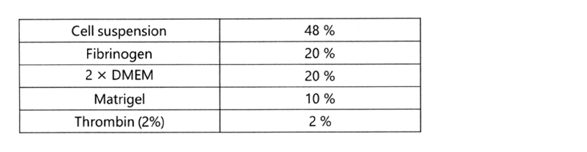
図18Aは、デバイスaを用いて作製した評価モデルの第3ユニットの第1開口部付近の拡大写真である。また、図18Bは、デバイスbを用いて作製した評価モデルの第3ユニットの第1開口部付近の拡大写真である。デバイスaおよびデバイスbを用いて作製した評価モデルは、軸索流路に軸索が伸び、そして、第1軸索通過孔(第2軸索通過孔)を軸索が通過していることを確認した。
[神経筋接合部の染色]
運動神経細胞と骨格筋細胞を共培養することで作製した評価モデルにおいて、神経筋接合部の形成の有無を、筋管細胞の蛍光染色によって確認した。まず、骨格筋細胞の培養に使用した培地と4%PFA/PBS(161-20141,WAKO,Tokyo,Japan)を半量ずつまぜた溶液をウェル入れて常温で5分静置した。その後、溶液を抜き取って4%PFA/PBをウェルに入れて常温で15分静置して固定化を行った。4%PFA/PBを抜き取り、PBSを入れて常温で10分おき、それを3回繰り返して洗浄した。その後PBSを抜き取って、0.3% TritonX-100(T8787-250ml,Sigma Aldrich,Missouri,USA)/PBSを入れ、常温で5分間膜貫通させた。ここでもまた、PBSで3回洗浄して1次抗体/基本液を入れて1時間静置してブロッキングを行った。基本液の組成は、10%Goat serum(S-1000,Vector Laboratories,California,USA)+0.01%TritonX-100/PBSを用いた。ブロッキング後は、1次抗体を2μg/mlの濃度になるように混ぜた基本液を入れて4℃で一晩反応させた。筋管細胞の免疫染色に用いた1次抗体は、TUJ1(845501,Biolegend,USA)である。次の日に溶液を抜き取ってPBSで3回洗浄し、2次抗体を4μg/mlの濃度になるように混ぜた基本液を入れて1時間反応させた。用いた2次抗体は、CF543(登録商標) Goat anti-rabbit IgG(H+L), Highly Vross-adsorbed,2mg/ml(20300,BIOTIUM,California,USA)である。アセチルコリンレセプターの染色には、拮抗剤であるα-ブンガロトキシンに蛍光色素をつけたFluoredcein-alpha-bungarotoxin(PK-CA707-00011,PromoKine,Heidelberg,Germany)を、終濃度4μg/mlになるように添加した。PBSで3回洗浄を行って、共焦点顕微鏡で観察した。
運動神経細胞と骨格筋細胞を共培養することで作製した評価モデルにおいて、神経筋接合部の形成の有無を、筋管細胞の蛍光染色によって確認した。まず、骨格筋細胞の培養に使用した培地と4%PFA/PBS(161-20141,WAKO,Tokyo,Japan)を半量ずつまぜた溶液をウェル入れて常温で5分静置した。その後、溶液を抜き取って4%PFA/PBをウェルに入れて常温で15分静置して固定化を行った。4%PFA/PBを抜き取り、PBSを入れて常温で10分おき、それを3回繰り返して洗浄した。その後PBSを抜き取って、0.3% TritonX-100(T8787-250ml,Sigma Aldrich,Missouri,USA)/PBSを入れ、常温で5分間膜貫通させた。ここでもまた、PBSで3回洗浄して1次抗体/基本液を入れて1時間静置してブロッキングを行った。基本液の組成は、10%Goat serum(S-1000,Vector Laboratories,California,USA)+0.01%TritonX-100/PBSを用いた。ブロッキング後は、1次抗体を2μg/mlの濃度になるように混ぜた基本液を入れて4℃で一晩反応させた。筋管細胞の免疫染色に用いた1次抗体は、TUJ1(845501,Biolegend,USA)である。次の日に溶液を抜き取ってPBSで3回洗浄し、2次抗体を4μg/mlの濃度になるように混ぜた基本液を入れて1時間反応させた。用いた2次抗体は、CF543(登録商標) Goat anti-rabbit IgG(H+L), Highly Vross-adsorbed,2mg/ml(20300,BIOTIUM,California,USA)である。アセチルコリンレセプターの染色には、拮抗剤であるα-ブンガロトキシンに蛍光色素をつけたFluoredcein-alpha-bungarotoxin(PK-CA707-00011,PromoKine,Heidelberg,Germany)を、終濃度4μg/mlになるように添加した。PBSで3回洗浄を行って、共焦点顕微鏡で観察した。
図19は、共焦点顕微鏡で撮像した写真で、図中の三角の先端の染色部分は、アセチルコリンレセプターの凝集が染色されたことを示している。神経筋接合部にはアセチルコリンレセプターが凝集して存在する。作製した評価モデルでアセチルコリンレセプターの凝集の染色が確認されたことから、作製した評価モデルには、神経筋接合部が形成されていることを確認した。
[神経筋接合部のフェノタイプの確認]
次に、神経筋接合部の形成を機能的に確認するため、運動神経細胞の単独刺激による骨格筋組織の収縮の確認を、デバイスaを用いて作製した評価モデルで行った。運動神経細胞の刺激にはグルタミン酸(070-00502,Wako,Tokyo,Japan)用いた。グルタミン酸は、下位運動神経へ作用することで、神経発火を促すことができる神経伝達物質であることが知られている。先ず、最終濃度400μMになるようにグルタミン酸を溶かしたMN培地を、第2培養槽に添加した。運動神経からの刺激が骨格筋組織に伝わって収縮を起こしていることを確認するため、約20秒後に、テトロドトキシン(TTX,206-11071,Wako,Tokyo,Japan)を、最終濃度2μMになるように第2培養槽に添加した。テトロドトキシンは、運動神経の興奮性膜のNaチャンネルを選択的に阻害する。薬剤添加前後の骨格筋組織の収縮はBZ-X710を用いて動画を撮影し、動画分析ソフトウェアPV Studio 2D(OA Science,Miyazaki,Japan)を用いて収縮の様子をグラフ化した。
次に、神経筋接合部の形成を機能的に確認するため、運動神経細胞の単独刺激による骨格筋組織の収縮の確認を、デバイスaを用いて作製した評価モデルで行った。運動神経細胞の刺激にはグルタミン酸(070-00502,Wako,Tokyo,Japan)用いた。グルタミン酸は、下位運動神経へ作用することで、神経発火を促すことができる神経伝達物質であることが知られている。先ず、最終濃度400μMになるようにグルタミン酸を溶かしたMN培地を、第2培養槽に添加した。運動神経からの刺激が骨格筋組織に伝わって収縮を起こしていることを確認するため、約20秒後に、テトロドトキシン(TTX,206-11071,Wako,Tokyo,Japan)を、最終濃度2μMになるように第2培養槽に添加した。テトロドトキシンは、運動神経の興奮性膜のNaチャンネルを選択的に阻害する。薬剤添加前後の骨格筋組織の収縮はBZ-X710を用いて動画を撮影し、動画分析ソフトウェアPV Studio 2D(OA Science,Miyazaki,Japan)を用いて収縮の様子をグラフ化した。
図20は、薬剤添加前後の骨格筋組織の収縮を示すグラフである。図20から明らかなように、グルタミン酸を第2培養槽、つまり、運動神経細胞に投与することで、骨格筋組織が収縮することを確認した。そして、テトロドトキシンを投与することで、骨格筋組織の収縮が停止することを確認した。以上の結果より、本明細書で開示するデバイスを用いて作製した評価モデルは、運動神経細胞の細胞体から伸びた軸索が骨格筋組織に接合し、神経筋接合部を形成していることを確認した。また、薬剤の添加により、骨格筋組織の収縮の程度が変化したことから、本明細書で開示する評価モデルを用いて、神経筋疾患の治療薬のスクリーニングができることを確認した。
〔軸索の染色〕
デバイスbを用いて作製した評価モデルを用い、以下の手順で軸索の染色を行った。染色試薬には、Cell Brite(登録商標) Cytoplasmic Membrane Dyes(30021,BIOTIUM,California,USA)を用いた。試薬:培地=5μm:1mlの割合で混ぜた溶液を被験物質投入孔から投入し、第1流路内に染色試薬を流して30分以上反応させた。その後、使用している培地で第1流路内を洗浄し、顕微鏡で観察した。
デバイスbを用いて作製した評価モデルを用い、以下の手順で軸索の染色を行った。染色試薬には、Cell Brite(登録商標) Cytoplasmic Membrane Dyes(30021,BIOTIUM,California,USA)を用いた。試薬:培地=5μm:1mlの割合で混ぜた溶液を被験物質投入孔から投入し、第1流路内に染色試薬を流して30分以上反応させた。その後、使用している培地で第1流路内を洗浄し、顕微鏡で観察した。
図21AおよびBは、顕微鏡で観察した写真で、同じ場所で明度を変えた写真である。写真中の矢印の先の明るくなっている部分が、染色された軸索である。第1流路に染色試薬を投入することで、第1流路内の軸索のみ選択的に染色できることを確認した。したがって、染色試薬に代え、神経筋疾患の治療薬の被験物質を用いれば、軸索に特異的に影響を与える治療薬のスクリーニングに使用できることを確認した。また、実施例1で作製したデバイスを用い、運動神経細胞と骨格筋細胞を共培養することで作製した評価モデルは、27日目に別の実験に使用するまで、運動神経細胞と骨格筋細胞の融合は見られなかった。図2に示す通り、非特許文献2に記載のデバイスを用いて作製した評価モデルは、共培養開始後14日目には、運動神経細胞がピラーを乗り越えたことが示されている。したがって、本明細書で開示するデバイスを用いて評価モデルを作製すると、従来のデバイスを用いて作製した評価モデルと比較して、長期間、運動神経細胞、運動神経細胞の細胞体から伸びた軸索、骨格筋組織が分離した状態で評価ができる。
<実施例3>
[軸索の断裂と再生の確認]
<実施例1>で作製したデバイス1bを用い、上記<実施例2>の(1)と同様の手順で運動神経細胞を培養した。培養終了後、シリンジポンプを用い、第1流路42bの一端42b1から、約60Paのせん断応力で培地を第1流路42bに流した。図22A乃至Cは、培養終了後の第3ユニット4の第2開口部45a付近の拡大写真である。図22Aは運動神経細胞の培養終了時の写真で、第2開口部45aから第1流路42bを通り、第1開口部45に伸長する軸索(図22Aの矢印)を確認した。図22Bは、約60Paのせん断応力で培地を流した後、約30秒経過後の写真で、軸索が断裂したことを確認した。図22Cは、軸索断裂後、約24時間経過した後の写真で、軸索が再生(図22Cの矢印)したことを確認した。以上の結果より、本出願で開示するデバイスを用いることで、軸索の断裂と再生ができることを確認した。
[軸索の断裂と再生の確認]
<実施例1>で作製したデバイス1bを用い、上記<実施例2>の(1)と同様の手順で運動神経細胞を培養した。培養終了後、シリンジポンプを用い、第1流路42bの一端42b1から、約60Paのせん断応力で培地を第1流路42bに流した。図22A乃至Cは、培養終了後の第3ユニット4の第2開口部45a付近の拡大写真である。図22Aは運動神経細胞の培養終了時の写真で、第2開口部45aから第1流路42bを通り、第1開口部45に伸長する軸索(図22Aの矢印)を確認した。図22Bは、約60Paのせん断応力で培地を流した後、約30秒経過後の写真で、軸索が断裂したことを確認した。図22Cは、軸索断裂後、約24時間経過した後の写真で、軸索が再生(図22Cの矢印)したことを確認した。以上の結果より、本出願で開示するデバイスを用いることで、軸索の断裂と再生ができることを確認した。
本出願で開示するデバイス、デバイスを用いて作製した評価モデル、評価モデルを用いたスクリーニング方法を用いることで、神経筋疾患の治療薬のスクリーニングができる。したがって、医療機関、大学、企業、研究機関等における創薬に有用である。
1、1a~1d…共培養用デバイス、2…第1ユニット、3…第2ユニット、4…第3ユニット、5…運動神経細胞培養用デバイス、5a…運動神経細胞培養用デバイス、6…蓋、10…骨格筋組織、11…軸索、21…第1基材、22…第1培養槽、23…ピラー、24…切欠部、31…第2基材、32…第2培養槽、33…第3ユニット挿入部、41…第3基材、42…軸索流路、42a…仮想軸索流路、42b…第1流路、42b1…第1流路の一端、42b2…第1流路の他端、42c…第2流路、42c1…第2流路の一端、42c2…第2流路の他端、42c3…第2流路用壁面、43…第3ユニットの一端部分、44…第3ユニットの他端部分、45…第1開口部、45a…第2開口部、211…第1基材の底面、212…第1基材の側壁面、221…第1培地投入孔、231…ピラーの一端、232…ピラーの他端、321…第2培地投入孔、411…第3基材開口部、421…軸索流路開口、422…軸索流路の他端、423…スリット、431…一端部分の側面、451…第1軸索通過孔、451’…第2軸索通過孔、451a、451’a…第1開口面、451b、451’b…第2開口面、500…マルチウェルプレート、501…基材、502…ウェル、503…一対の電極、504…回路
Claims (12)
- 運動神経細胞と骨格筋細胞の共培養用デバイスであって、
デバイスは、
骨格筋組織形成用の第1ユニットと、
運動神経細胞培養用の第2ユニットと、
第1ユニットと第2ユニットとを連通するための第3ユニットと、
骨格筋組織形成の足場となるピラーと、
を含み、
第1ユニットは、
第1基材と、
第1基材に形成された第1培養槽と、
を含み、
第2ユニットは、
第2基材と、
第2基材に形成された第2培養槽と、
を含み、
第3ユニットは、
第3基材と、
第3基材に形成され、軸索の束が通る軸索流路と、
を含み、
第3ユニットの一端部分は第2ユニットに連結することができ、第3ユニットの一端部分と第2ユニットとを連結した時には、軸索流路と第2培養槽とを連通することができ、
第3ユニットの他端部分には第1開口部が軸索流路に接するように形成され、第1開口部には、第1軸索通過孔が1以上形成され、
第1軸索通過孔は、運動神経細胞および骨格筋細胞は通過できないが、軸索が通過できる大きさであり、
ピラーの少なくとも一部は、第1培養槽内に配置できる、
デバイス。 - 軸索流路が、
第1流路と、
第1流路の内側に形成された第2流路と、
を含み、
第1開口部は、第1流路に接するように形成され、
第2流路は、
一端が第2培養槽に連通することができ、
他端には、第2開口部が接するように形成され、
第2開口部には、
第2軸索通過孔が1以上形成され、
第2軸索通過孔は、運動神経細胞および骨格筋細胞は通過できないが、軸索が通過できる大きさであり、
第1開口部と第2開口部は離間して配置されている、
請求項1に記載のデバイス。 - 2以上の第3ユニットが、積層されている、
請求項1または2に記載のデバイス。 - 第1ユニット、第2ユニット、第3ユニット、および、ピラーの位置関係は、
ピラーが2本以上含まれる場合は、2本以上のピラーを結んだ仮想面の何れかと、軸索流路を第1培養槽に仮想的に延長した仮想軸索流路が交わるように配置され、
ピラーが1本の場合は、1本のピラーが形成する仮想面、または、ピラーと第3ユニットの他端部分で形成する仮想面と、軸索流路を第1培養槽に仮想的に延長した仮想軸索流路が交わるように配置される、
請求項1~3の何れか一項に記載のデバイス。 - ピラーが2本含まれ、各々のピラーの一端は第1基材21に連結し、他端は第1培養槽内に片持ち状に配置される、
請求項4に記載のデバイス。 - 第1軸索通過孔の大きさが、
最小距離が0.5μm以上、2.5μm以下、または、
最小距離が0.5μm以上で、断面積が60μm2以下である、
請求項1~5の何れか一項に記載のデバイス。 - 第2ユニットと第3ユニットを連結することで運動神経細胞培養用デバイスを作製し、
一つの第1ユニットに対して、2以上の運動神経細胞培養用デバイスが配置される、
請求項1~6の何れか一項に記載のデバイス。 - 一つの第2ユニットに2以上の第3ユニットを連結することで運動神経細胞培養用デバイスを作製し、
任意の第3ユニットの他端に第1ユニットが配置される、
請求項1~6の何れか一項に記載のデバイス。 - 運動神経細胞と骨格筋細胞の共培養用デバイスに用いられる運動神経細胞培養用デバイスであって、
デバイスは、
運動神経細胞培養用の第2ユニットと、
第2ユニットに連結した第3ユニットと、
を含み、
第2ユニットは、
第2基材と、
第2基材に形成された第2培養槽と、
を含み、
第3ユニットは、
第3基材と、
第3基材に形成され、軸索の束が通る軸索流路と、
を含み、
第3ユニットの一端と第2ユニットは連結し、軸索流路の一端は第2培養槽に連通し、
第3ユニットの他端部分には第1開口部が軸索流路に接するように形成され、第1開口部には、第1軸索通過孔が1以上形成され、
第1軸索通過孔は、運動神経細胞および骨格筋細胞は通過できないが、軸索が通過できる大きさである、
デバイス。 - 少なくとも2以上のウェルを有し、
前記ウェルの少なくとも1つに、請求項1~9の何れか一項に記載のデバイスが配置されている、
マルチウェルプレート。 - 請求項1~8の何れか一項に記載のデバイスを用いた神経筋疾患のin vitro評価モデルの作製方法であって、
作製方法は、
第2ユニットで運動神経細胞を培養する運動神経細胞培養工程と、
第1ユニットで骨格筋細胞を培養し、骨格筋組織を作製する骨格筋組織作製工程と、
培養した運動神経細胞の細胞体から伸びた軸索が、第3ユニットの軸索流路を通り、作製した骨格筋組織と接合することで神経筋接合部を作製する神経筋接合部作製工程と、
を含む、神経筋疾患のin vitro評価モデルの作製方法。 - 請求項11に記載の作製方法で作製した神経筋疾患のin vitro評価モデルを用いた神経筋疾患の治療薬のスクリーニング方法であって、
スクリーニング方法は、
作製した評価モデルの運動神経細胞、運動神経細胞の細胞体から伸びた軸索、骨格筋組織の何れか一つに被験物質を投与する被験物質投与工程と、
運動神経細胞、運動神経細胞の細胞体から伸びた軸索、骨格筋組織の少なくとも一つの状態を測定する測定工程と、
測定工程の結果より、被験物質が神経筋疾患の治療薬として作用するのか評価する被験物質評価工程と、
を含む、
スクリーニング方法。
Priority Applications (2)
| Application Number | Priority Date | Filing Date | Title |
|---|---|---|---|
| JP2021502011A JP7287704B2 (ja) | 2019-02-20 | 2020-02-18 | 共培養用デバイス、運動神経細胞培養用デバイス、マルチウェルプレート、神経筋疾患のin vitro評価モデルの作製方法、および、神経筋疾患の治療薬のスクリーニング方法 |
| US17/431,992 US20210380913A1 (en) | 2019-02-20 | 2020-02-18 | Co-culturing device, motor neuron culturing device, multi-well plate, fabrication method of in vitro evaluation model of neuromuscular disease, and screening method of therapeutic agent against neuromuscular disease |
Applications Claiming Priority (2)
| Application Number | Priority Date | Filing Date | Title |
|---|---|---|---|
| JP2019-028451 | 2019-02-20 | ||
| JP2019028451 | 2019-02-20 |
Publications (1)
| Publication Number | Publication Date |
|---|---|
| WO2020171052A1 true WO2020171052A1 (ja) | 2020-08-27 |
Family
ID=72144587
Family Applications (1)
| Application Number | Title | Priority Date | Filing Date |
|---|---|---|---|
| PCT/JP2020/006221 Ceased WO2020171052A1 (ja) | 2019-02-20 | 2020-02-18 | 共培養用デバイス、運動神経細胞培養用デバイス、マルチウェルプレート、神経筋疾患のin vitro評価モデルの作製方法、および、神経筋疾患の治療薬のスクリーニング方法 |
Country Status (3)
| Country | Link |
|---|---|
| US (1) | US20210380913A1 (ja) |
| JP (1) | JP7287704B2 (ja) |
| WO (1) | WO2020171052A1 (ja) |
Cited By (1)
| Publication number | Priority date | Publication date | Assignee | Title |
|---|---|---|---|---|
| WO2024202409A1 (ja) * | 2023-03-30 | 2024-10-03 | ウシオ電機株式会社 | 神経細胞培養チップ |
Families Citing this family (2)
| Publication number | Priority date | Publication date | Assignee | Title |
|---|---|---|---|---|
| EP4493672A4 (en) | 2022-03-16 | 2026-03-18 | Ananda Devices Inc | DEVICES AND METHODS FOR PREPARING IN VITRO MODELS OF NEUROMUSCULAR JUNCTIONS |
| KR102883205B1 (ko) * | 2022-10-26 | 2025-11-10 | 서강대학교산학협력단 | 3차원 신경근접합부 모델, 이의 제조 방법 및 이를 이용한 약물 스크리닝 방법 |
Citations (2)
| Publication number | Priority date | Publication date | Assignee | Title |
|---|---|---|---|---|
| US20170355945A1 (en) * | 2016-06-13 | 2017-12-14 | Massachusetts Institute Of Technology | Microfluidic Device for Three Dimensional and Compartmentalized Coculture of Neuronal and Muscle Cells, with Functional Force Readout |
| JP2019000093A (ja) * | 2017-06-14 | 2019-01-10 | 一般財団法人生産技術研究奨励会 | 神経細胞を培養する装置、神経細胞を培養する方法、軸索束の形態変性を配向性解析によって数値化する方法、神経組織、軸索束内のプロテインを解析及び同定する方法並びに神経細胞の使用方法 |
-
2020
- 2020-02-18 US US17/431,992 patent/US20210380913A1/en active Pending
- 2020-02-18 JP JP2021502011A patent/JP7287704B2/ja active Active
- 2020-02-18 WO PCT/JP2020/006221 patent/WO2020171052A1/ja not_active Ceased
Patent Citations (2)
| Publication number | Priority date | Publication date | Assignee | Title |
|---|---|---|---|---|
| US20170355945A1 (en) * | 2016-06-13 | 2017-12-14 | Massachusetts Institute Of Technology | Microfluidic Device for Three Dimensional and Compartmentalized Coculture of Neuronal and Muscle Cells, with Functional Force Readout |
| JP2019000093A (ja) * | 2017-06-14 | 2019-01-10 | 一般財団法人生産技術研究奨励会 | 神経細胞を培養する装置、神経細胞を培養する方法、軸索束の形態変性を配向性解析によって数値化する方法、神経組織、軸索束内のプロテインを解析及び同定する方法並びに神経細胞の使用方法 |
Non-Patent Citations (1)
| Title |
|---|
| YAMAOKA, N. ET AL.: "Open-Chamber Co-Culture Microdevices for Single- Cell Analysis of Skeletal Muscle Myotubes and Motor Neurons with Neuromuscular Junctions", BIOCHIP JOURNAL, vol. 13, no. 2, 1 April 2019 (2019-04-01), pages 127 - 132, XP036818438, DOI: 10.1007/s13206-018-3202-3 * |
Cited By (1)
| Publication number | Priority date | Publication date | Assignee | Title |
|---|---|---|---|---|
| WO2024202409A1 (ja) * | 2023-03-30 | 2024-10-03 | ウシオ電機株式会社 | 神経細胞培養チップ |
Also Published As
| Publication number | Publication date |
|---|---|
| JPWO2020171052A1 (ja) | 2020-08-27 |
| US20210380913A1 (en) | 2021-12-09 |
| JP7287704B2 (ja) | 2023-06-06 |
Similar Documents
| Publication | Publication Date | Title |
|---|---|---|
| US10725021B2 (en) | Muscle chips and methods of use thereof | |
| EP2721141B1 (en) | Device and method for culturing cells in a biomimetic environment | |
| CN111218404A (zh) | 一种仿生多器官芯片及其制备方法和应用 | |
| Jeon et al. | Hot embossing for fabrication of a microfluidic 3D cell culture platform | |
| Dodson et al. | Retina-on-a-chip: a microfluidic platform for point access signaling studies | |
| US9121847B2 (en) | Three-dimensional microfluidic platforms and methods of use thereof | |
| CN105170208B (zh) | 一种微阵列芯片的制备方法及其产品 | |
| US20150313704A1 (en) | Cardiac tissue constructs and methods of fabrication thereof | |
| US20120142556A1 (en) | High throughput assays for determining contractile function and devices for use therein | |
| JP6256853B1 (ja) | 3次元細胞構造体の製造方法およびそれに用いる支持体 | |
| WO2004046337A2 (en) | Multilayered microcultures | |
| CN104342369B (zh) | 一种采用微流控芯片构建三维神经网络的装置及其制备和使用方法 | |
| JP7287704B2 (ja) | 共培養用デバイス、運動神経細胞培養用デバイス、マルチウェルプレート、神経筋疾患のin vitro評価モデルの作製方法、および、神経筋疾患の治療薬のスクリーニング方法 | |
| JP2023505989A (ja) | 微細工学組織障壁システム | |
| CN114181833A (zh) | 一种基于纤维蛋白凝胶模拟病理性血脑屏障的仿生微流控芯片及其构建方法 | |
| Palaninathan et al. | Multi-organ on a chip for personalized precision medicine | |
| CN212316139U (zh) | 一种仿生多器官芯片 | |
| Py et al. | From understanding cellular function to novel drug discovery: the role of planar patch-clamp array chip technology | |
| Lovchik et al. | Overflow microfluidic networks for open and closed cell cultures on chip | |
| Emon et al. | Developing a multi-functional sensor for cell traction force, matrix remodeling and biomechanical assays in self-assembled 3D tissues in vitro | |
| Ren | Towards brain-on-a-chip: Microfluidic and microelectrode array platforms for morphological and electrophysiological observations on the propagation of Alzheimer's disease | |
| Samara | A 3D Printed Hanging Drop Platform for Spheroid Production, Pick-up, and Patterning | |
| Park | Microsystems for in vitro CNS neuron study | |
| Moraes | Manipulating the Mechanical Microenvironment: Microdevices for High-throughput Studies in Cellular Mechanobiology | |
| Cheng | Microfluidic Platforms for Focal Stimulation of Muscle Cells and Large-scale Studies of Synaptogenesis |
Legal Events
| Date | Code | Title | Description |
|---|---|---|---|
| 121 | Ep: the epo has been informed by wipo that ep was designated in this application |
Ref document number: 20759605 Country of ref document: EP Kind code of ref document: A1 |
|
| DPE2 | Request for preliminary examination filed before expiration of 19th month from priority date (pct application filed from 20040101) | ||
| ENP | Entry into the national phase |
Ref document number: 2021502011 Country of ref document: JP Kind code of ref document: A |
|
| NENP | Non-entry into the national phase |
Ref country code: DE |
|
| 122 | Ep: pct application non-entry in european phase |
Ref document number: 20759605 Country of ref document: EP Kind code of ref document: A1 |