WO2020170960A1 - エネルギー貯蔵デバイス電極用薄膜形成用組成物 - Google Patents
エネルギー貯蔵デバイス電極用薄膜形成用組成物 Download PDFInfo
- Publication number
- WO2020170960A1 WO2020170960A1 PCT/JP2020/005781 JP2020005781W WO2020170960A1 WO 2020170960 A1 WO2020170960 A1 WO 2020170960A1 JP 2020005781 W JP2020005781 W JP 2020005781W WO 2020170960 A1 WO2020170960 A1 WO 2020170960A1
- Authority
- WO
- WIPO (PCT)
- Prior art keywords
- energy storage
- storage device
- group
- electrode
- thin film
- Prior art date
- Legal status (The legal status is an assumption and is not a legal conclusion. Google has not performed a legal analysis and makes no representation as to the accuracy of the status listed.)
- Ceased
Links
Images
Classifications
-
- H—ELECTRICITY
- H01—ELECTRIC ELEMENTS
- H01M—PROCESSES OR MEANS, e.g. BATTERIES, FOR THE DIRECT CONVERSION OF CHEMICAL ENERGY INTO ELECTRICAL ENERGY
- H01M4/00—Electrodes
- H01M4/02—Electrodes composed of, or comprising, active material
- H01M4/13—Electrodes for accumulators with non-aqueous electrolyte, e.g. for lithium-accumulators; Processes of manufacture thereof
- H01M4/139—Processes of manufacture
-
- H—ELECTRICITY
- H01—ELECTRIC ELEMENTS
- H01G—CAPACITORS; CAPACITORS, RECTIFIERS, DETECTORS, SWITCHING DEVICES, LIGHT-SENSITIVE OR TEMPERATURE-SENSITIVE DEVICES OF THE ELECTROLYTIC TYPE
- H01G11/00—Hybrid capacitors, i.e. capacitors having different positive and negative electrodes; Electric double-layer [EDL] capacitors; Processes for the manufacture thereof or of parts thereof
- H01G11/22—Electrodes
- H01G11/26—Electrodes characterised by their structure, e.g. multi-layered, porosity or surface features
- H01G11/28—Electrodes characterised by their structure, e.g. multi-layered, porosity or surface features arranged or disposed on a current collector; Layers or phases between electrodes and current collectors, e.g. adhesives
-
- H—ELECTRICITY
- H01—ELECTRIC ELEMENTS
- H01G—CAPACITORS; CAPACITORS, RECTIFIERS, DETECTORS, SWITCHING DEVICES, LIGHT-SENSITIVE OR TEMPERATURE-SENSITIVE DEVICES OF THE ELECTROLYTIC TYPE
- H01G11/00—Hybrid capacitors, i.e. capacitors having different positive and negative electrodes; Electric double-layer [EDL] capacitors; Processes for the manufacture thereof or of parts thereof
- H01G11/84—Processes for the manufacture of hybrid or EDL capacitors, or components thereof
- H01G11/86—Processes for the manufacture of hybrid or EDL capacitors, or components thereof specially adapted for electrodes
-
- H—ELECTRICITY
- H01—ELECTRIC ELEMENTS
- H01M—PROCESSES OR MEANS, e.g. BATTERIES, FOR THE DIRECT CONVERSION OF CHEMICAL ENERGY INTO ELECTRICAL ENERGY
- H01M10/00—Secondary cells; Manufacture thereof
- H01M10/05—Accumulators with non-aqueous electrolyte
- H01M10/052—Li-accumulators
- H01M10/0525—Rocking-chair batteries, i.e. batteries with lithium insertion or intercalation in both electrodes; Lithium-ion batteries
-
- H—ELECTRICITY
- H01—ELECTRIC ELEMENTS
- H01M—PROCESSES OR MEANS, e.g. BATTERIES, FOR THE DIRECT CONVERSION OF CHEMICAL ENERGY INTO ELECTRICAL ENERGY
- H01M4/00—Electrodes
- H01M4/02—Electrodes composed of, or comprising, active material
-
- H—ELECTRICITY
- H01—ELECTRIC ELEMENTS
- H01M—PROCESSES OR MEANS, e.g. BATTERIES, FOR THE DIRECT CONVERSION OF CHEMICAL ENERGY INTO ELECTRICAL ENERGY
- H01M4/00—Electrodes
- H01M4/02—Electrodes composed of, or comprising, active material
- H01M4/04—Processes of manufacture in general
-
- H—ELECTRICITY
- H01—ELECTRIC ELEMENTS
- H01M—PROCESSES OR MEANS, e.g. BATTERIES, FOR THE DIRECT CONVERSION OF CHEMICAL ENERGY INTO ELECTRICAL ENERGY
- H01M4/00—Electrodes
- H01M4/02—Electrodes composed of, or comprising, active material
- H01M4/13—Electrodes for accumulators with non-aqueous electrolyte, e.g. for lithium-accumulators; Processes of manufacture thereof
-
- H—ELECTRICITY
- H01—ELECTRIC ELEMENTS
- H01M—PROCESSES OR MEANS, e.g. BATTERIES, FOR THE DIRECT CONVERSION OF CHEMICAL ENERGY INTO ELECTRICAL ENERGY
- H01M4/00—Electrodes
- H01M4/02—Electrodes composed of, or comprising, active material
- H01M4/62—Selection of inactive substances as ingredients for active masses, e.g. binders, fillers
-
- H—ELECTRICITY
- H01—ELECTRIC ELEMENTS
- H01M—PROCESSES OR MEANS, e.g. BATTERIES, FOR THE DIRECT CONVERSION OF CHEMICAL ENERGY INTO ELECTRICAL ENERGY
- H01M4/00—Electrodes
- H01M4/02—Electrodes composed of, or comprising, active material
- H01M4/62—Selection of inactive substances as ingredients for active masses, e.g. binders, fillers
- H01M4/621—Binders
- H01M4/622—Binders being polymers
-
- H—ELECTRICITY
- H01—ELECTRIC ELEMENTS
- H01M—PROCESSES OR MEANS, e.g. BATTERIES, FOR THE DIRECT CONVERSION OF CHEMICAL ENERGY INTO ELECTRICAL ENERGY
- H01M4/00—Electrodes
- H01M4/02—Electrodes composed of, or comprising, active material
- H01M4/64—Carriers or collectors
- H01M4/66—Selection of materials
-
- Y—GENERAL TAGGING OF NEW TECHNOLOGICAL DEVELOPMENTS; GENERAL TAGGING OF CROSS-SECTIONAL TECHNOLOGIES SPANNING OVER SEVERAL SECTIONS OF THE IPC; TECHNICAL SUBJECTS COVERED BY FORMER USPC CROSS-REFERENCE ART COLLECTIONS [XRACs] AND DIGESTS
- Y02—TECHNOLOGIES OR APPLICATIONS FOR MITIGATION OR ADAPTATION AGAINST CLIMATE CHANGE
- Y02E—REDUCTION OF GREENHOUSE GAS [GHG] EMISSIONS, RELATED TO ENERGY GENERATION, TRANSMISSION OR DISTRIBUTION
- Y02E60/00—Enabling technologies; Technologies with a potential or indirect contribution to GHG emissions mitigation
- Y02E60/10—Energy storage using batteries
Definitions
- the present invention relates to a thin film forming composition for an energy storage device electrode.
- this undercoat layer is expected to enhance the adhesion to the electrode mixture layer and the current collector and suppress deterioration due to interfacial peeling, but the conductive carbon material is a solid (powder), Since the interaction with the current collector and the electrode layer is weak, a component having a high adhesive force other than the conductive carbon material is necessary for the undercoat layer to strongly adhere to the current collector and the electrode layer. However, when the amount of the component other than the conductive carbon material increases, the amount of the insulating component increases, so that the conductivity of the undercoat layer decreases, and there is a problem that the intended effect of lowering the resistance of the battery is impaired.
- the dispersion containing the conductive carbon material used in forming these undercoat layers does not always have good storage stability, and often causes problems such as aggregation of the conductive carbon material during storage, and Since the distributed processing itself is costly, there is a problem that the manufacturing cost becomes high.
- the present invention has been made in view of such circumstances, in the energy storage device electrode, it is possible to achieve good adhesion to the electrode mixture layer and the current collector, and without containing a conductive carbon material. Nevertheless, it is an object to provide a composition for forming a thin film for an energy storage device electrode, which gives a thin film functioning as an undercoat layer.
- the present inventors have found that a composition containing a polymer having an oxazoline group in a side chain and containing no conductive carbon material has an electrode mixture layer or a current collector.
- the inventors have found that a thin film that can exhibit good adhesion to the above and can function as an undercoat layer in spite of not containing a conductive carbon material is provided, and completed the present invention.
- the present invention is 1.
- a composition for forming a thin film for an energy storage device electrode which contains a polymer having an oxazoline group in a side chain and a solvent, and does not contain a conductive carbon material, 2.
- a thin film-forming composition for an energy storage device electrode which is for forming a thin film interposed between a current collector of an energy storage device and an electrode mixture layer, 3.
- the polymer is a radical polymerization product of at least two kinds of monomers, an oxazoline monomer having a polymerizable carbon-carbon double bond-containing group at the 2-position and a (meth)acrylic monomer having a hydrophilic functional group.
- Energy storage device electrode thin film forming composition 4.
- the polymer is an oxazoline monomer represented by the formula (1) having a polymerizable carbon-carbon double bond-containing group at the 2-position, (meth)acrylic acid, 2-hydroxyethyl acrylate, methoxypolyethylene glycol acrylate, and acrylic.
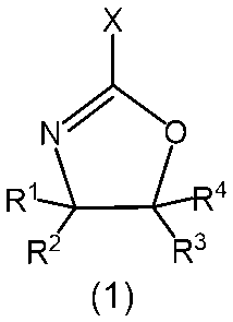
- a thin film forming composition for energy storage device electrodes which is a radical polymer of a (meth)acrylic monomer having one or more hydrophilic functional groups selected from (In the formula, X represents a chain hydrocarbon group containing a polymerizable carbon-carbon double bond, R 1 to R 4 are each independently a hydrogen atom, a halogen atom, or a branched chain having 1 to 5 carbon atoms. It represents an alkyl group which may have a structure, an aryl group having 6 to 20 carbon atoms, or an aralkyl group having 7 to 20 carbon atoms.) 5.
- a composite current collector for an electrode of an energy storage device which comprises an undercoat layer of 7. 6, an electrode for an energy storage device, comprising a composite current collector for an electrode of the energy storage device, 8.
- An energy storage device comprising an electrode for an energy storage device according to 7. 9.
- Eight energy storage devices which are lithium-ion secondary batteries.
- composition for forming a thin film for an energy storage device electrode of the present invention does not contain a conductive carbon material, it exhibits excellent adhesion to the electrode mixture layer and the current collector. Also, the composition of the present invention provides a thin film that functions as an undercoat layer, even though it does not contain a conductive carbon material.
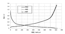
- FIG. 6 is a diagram showing a cycle test result of a secondary battery using the electrodes D, E and F produced in Example 4-1, Comparative example 4-1 and Comparative example 4-2.
- the composition for forming a thin film for an energy storage device electrode according to the present invention (hereinafter, simply referred to as a composition) is characterized by containing a polymer having an oxazoline group in a side chain and a solvent and not containing a conductive carbon material.
- the conductive carbon material is a carbon material such as carbon black, ketjen black, acetylene black, carbon whiskers, carbon nanotube (CNT), carbon fiber, natural graphite, artificial graphite, etc., which itself has conductivity.
- a polymer having an oxazoline group in a side chain is a polymer in which an oxazoline group is bonded to a repeating unit constituting a main chain either directly or through a spacer group such as an alkylene group.
- an oxazoline obtained by radical polymerization of an oxazoline monomer having a polymerizable carbon-carbon double bond-containing group at the 2-position as shown in formula (1) is preferable.
- X represents a polymerizable carbon-carbon double bond-containing group
- R 1 to R 4 are each independently a hydrogen atom, a halogen atom, an alkyl group having 1 to 5 carbon atoms, or an alkyl group having 6 to 20 carbon atoms. It represents an aryl group or an aralkyl group having 7 to 20 carbon atoms.
- the polymerizable carbon-carbon double bond-containing group contained in the oxazoline monomer is not particularly limited as long as it contains a polymerizable carbon-carbon double bond, but a chain containing a polymerizable carbon-carbon double bond.
- a hydrocarbon group is preferable, and for example, an alkenyl group having 2 to 8 carbon atoms such as a vinyl group, an allyl group and an isopropenyl group is preferable.
- examples of the halogen atom include a fluorine atom, a chlorine atom, a bromine atom, and an iodine atom.
- the alkyl group having 1 to 5 carbon atoms may be linear, branched or cyclic, and examples thereof include methyl group, ethyl group, n-propyl group, isopropyl group, n-butyl group and sec-butyl group.
- aryl group having 6 to 20 carbon atoms include phenyl group, xylyl group, tolyl group, biphenyl group and naphthyl group.
- aralkyl group having 7 to 20 carbon atoms include benzyl group, phenylethyl group and phenylcyclohexyl group.
- oxazoline monomer having a polymerizable carbon-carbon double bond-containing group at the 2-position represented by the formula (1) include 2-vinyl-2-oxazoline, 2-vinyl-4-methyl-2-oxazoline, 2-vinyl-4-ethyl-2-oxazoline, 2-vinyl-4-propyl-2-oxazoline, 2-vinyl-4-butyl-2-oxazoline, 2-vinyl-5-methyl-2-oxazoline, 2- Vinyl-5-ethyl-2-oxazoline, 2-vinyl-5-propyl-2-oxazoline, 2-vinyl-5-butyl-2-oxazoline, 2-isopropenyl-2-oxazoline, 2-isopropenyl-4- Methyl-2-oxazoline, 2-isopropenyl-4-ethyl-2-oxazoline, 2-isopropenyl-4-propyl-2-oxazoline, 2-isopropenyl-4-buty
- the oxazoline polymer is also preferably water-soluble.
- a water-soluble oxazoline polymer may be a homopolymer of the oxazoline monomer represented by the above formula (1), but it has the above-mentioned oxazoline monomer and a hydrophilic functional group (metapolymer) in order to further improve the solubility in water.
- metal hydrophilic functional group metalapolymer
- it is obtained by radical polymerization of at least two kinds of monomers including an acrylic acid ester-based monomer.
- (meth)acrylic monomer having a hydrophilic functional group examples include (meth)acrylic acid, 2-hydroxyethyl acrylate, methoxypolyethylene glycol acrylate, monoester product of acrylic acid and polyethylene glycol, acrylic acid.
- 2-Aminoethyl and salts thereof 2-hydroxyethyl methacrylate, methoxypolyethylene glycol methacrylate, monoesters of methacrylic acid and polyethylene glycol, 2-aminoethyl methacrylate and salts thereof, sodium (meth)acrylate, ( Examples thereof include ammonium (meth)acrylate, (meth)acrylonitrile, (meth)acrylamide, N-methylol (meth)acrylamide, N-(2-hydroxyethyl)(meth)acrylamide, sodium styrenesulfonate, and the like. They may be used alone or in combination of two or more. Among these, methoxypolyethylene glycol (meth)acrylic acid and monoester products of (meth)acrylic acid and polyethylene glycol are preferable.
- the oxazoline monomer and other monomer other than the (meth)acrylic monomer having a hydrophilic functional group are used in combination within a range that does not adversely affect the adhesion of the thin film obtained from the composition of the present invention to the current collector and the like. can do.
- Specific examples of other monomers include methyl (meth)acrylate, ethyl (meth)acrylate, butyl (meth)acrylate, 2-ethylhexyl (meth)acrylate, stearyl (meth)acrylate, and (meth)acrylic.
- (Meth)acrylic acid ester monomers such as perfluoroethyl acid and phenyl (meth)acrylate; ⁇ -olefin monomers such as ethylene, propylene, butene and pentene; haloolefins such as vinyl chloride, vinylidene chloride and vinyl fluoride Monomers: Styrene-based monomers such as styrene and ⁇ -methylstyrene; vinyl carboxylic acid ester-based monomers such as vinyl acetate and vinyl propionate; vinyl ether-based monomers such as methyl vinyl ether and ethyl vinyl ether, and these are used alone. Alternatively, two or more kinds may be used in combination.
- the content of the oxazoline monomer is preferably 10% by mass or more, and 20% by mass, from the viewpoint of further enhancing the adhesion of the obtained thin film to the current collector and the like.
- the above is more preferable, and 30 mass% or more is still more preferable.
- the upper limit of the content of the oxazoline monomer in the monomer component is 100% by mass, and in this case, a homopolymer of the oxazoline monomer is obtained.
- the content of the (meth)acrylic monomer having a hydrophilic functional group in the monomer component is preferably 10% by mass or more, more preferably 20% by mass or more. , 30% by mass or more is even more preferable.
- the content of the other monomer in the monomer component is, as described above, in a range that does not affect the adhesion of the obtained thin film to the current collector and the like, and is generally determined because it varies depending on the type. Although not possible, it may be appropriately set in the range of 5 to 95% by mass, preferably 10 to 90% by mass.
- the average molecular weight of the oxazoline polymer is not particularly limited, but the weight average molecular weight is preferably 1,000 to 2,000,000, more preferably 2,000 to 1,000,000.
- the weight average molecular weight is a polystyrene conversion value by gel permeation chromatography.
- the oxazoline polymer used in the present invention can be produced by polymerizing the above-mentioned various monomers by a known radical polymerization method described in, for example, JP-A-6-32844 and JP-A-2013-72002. ..
- the oxazoline polymer that can be used in the present invention can be obtained as a commercial product, and examples of such a commercial product include Epocros WS-300 (manufactured by Nippon Shokubai Co., Ltd., solid content concentration 10% by mass, Aqueous solution), Epocros WS-700 (manufactured by Nippon Shokubai Co., Ltd., solid content concentration 25 mass%, aqueous solution), Epocros WS-500 (manufactured by Nippon Shokubai Co., Ltd., solid content concentration 39 mass%, water/1-methoxy- 2-propanol solution), Poly(2-ethyl-2-oxazoline) (Aldrich), Poly(2-ethyl-2-oxazoline) (AlfaAesar), Poly(2-ethyl-2-oxazoline) (VWR International, LLC) Etc. When commercially available as a solution, it may be used as it is or after being replaced with a target solvent.
- the solvent is not particularly limited as long as it has been conventionally used for preparing a composition of this type, and examples thereof include water; ethers such as tetrahydrofuran (THF), diethyl ether, and 1,2-dimethoxyethane (DME).
- ethers such as tetrahydrofuran (THF), diethyl ether, and 1,2-dimethoxyethane (DME).
- Halogenated hydrocarbons such as methylene chloride, chloroform, 1,2-dichloroethane; N,N-dimethylformamide (DMF), N,N-dimethylacetamide (DMAc), N-methyl-2-pyrrolidone (NMP), etc.
- ketones such as acetone, methyl ethyl ketone, methyl isobutyl ketone, cyclohexanone
- alcohols such as methanol, ethanol, isopropanol, n-butanol, t-butanol, n-propanol; n-heptane, n-hexane, cyclohexane, etc.
- Aliphatic hydrocarbons benzene, toluene, xylene, ethylbenzene and other aromatic hydrocarbons; ethylene glycol monoethyl ether, ethylene glycol monobutyl ether, propylene glycol monomethyl ether and other glycol ethers; ethylene glycol, propylene glycol, etc.
- Organic solvents such as glycols may be mentioned. These solvents can be used alone or in combination of two or more.
- water, NMP, DMF, THF, methanol, ethanol, n-propanol, isopropanol, n-butanol and t-butanol are preferable.
- solvents may be used alone or in combination of two or more for the purpose of improving coatability and reducing costs.
- the film-forming property is good even when a hydrophilic solvent such as alcohols, glycol ethers, and glycols is used, and further, a mixed solvent of the hydrophilic solvent and water or Even when water is used as the sole solvent, the film forming property does not deteriorate.
- a hydrophilic solvent such as alcohols, glycol ethers, and glycols
- a mixed solvent of the hydrophilic solvent and water or Even when water is used as the sole solvent the film forming property does not deteriorate.
- a mixed solvent of a hydrophilic solvent and water or a water single solvent also in the composition of the present invention. ..
- the composition of the present invention may contain the above-mentioned solvent-soluble crosslinking agent.
- the cross-linking agent may be either a compound that causes a cross-linking reaction with the oxazoline group of the oxazoline polymer or a self-cross-linking compound, but a compound that causes a cross-linking reaction with the oxazoline group may be used in order to further improve the solvent resistance of the obtained thin film. preferable.
- the compound that causes a crosslinking reaction with an oxazoline group may be, for example, a compound having two or more functional groups having reactivity with an oxazoline group such as a carboxyl group, a hydroxyl group, a thiol group, an amino group, a sulfinic acid group, and an epoxy group.
- a compound having two or more carboxyl groups is preferable.
- the compound having a functional group that causes a crosslinking reaction by heating during the formation of a thin film or in the presence of an acid catalyst and causing the above-mentioned functional group for example, a sodium salt, potassium salt, lithium salt, or ammonium salt of carboxylic acid is also crosslinked.
- the compound that causes a crosslinking reaction with an oxazoline group include metal salts of synthetic polymers such as polyacrylic acid and its copolymers and natural polymers such as carboxymethylcellulose and alginic acid, which exhibit crosslinking reactivity in the presence of an acid catalyst.
- Such a compound that causes a cross-linking reaction with an oxazoline group can be obtained as a commercially available product, and examples of such a commercially available product include sodium polyacrylate (manufactured by Fuji Film Wako Pure Chemical Industries, Ltd., polymerization degree: 2).
- Examples of the self-crosslinking compound include an aldehyde group for a hydroxyl group, an epoxy group, a vinyl group, an isocyanate group, an alkoxy group, a carboxyl group for an aldehyde group, an amino group, an isocyanate group, an epoxy group, and an amino group.
- cross-linking functional groups that react with each other, such as isocyanate groups and aldehyde groups, hydroxyl groups (dehydration condensation) reacting with the same cross-linking functional groups, mercapto groups (disulfide bonds), esters
- examples thereof include compounds having a group (Claisen condensation), a silanol group (dehydration condensation), a vinyl group, an acrylic group, and the like.
- the self-crosslinking compound include a polyfunctional acrylate that exhibits crosslinking reactivity in the presence of an acid catalyst, tetraalkoxysilane, a monomer having a blocked isocyanate group, and at least one of a hydroxyl group, a carboxylic acid, and an amino group.
- examples thereof include block copolymers of monomers.
- Such a self-crosslinking compound can also be obtained as a commercial product, and examples of such a commercially available product include polyfunctional acrylates such as A-9300 (ethoxylated isocyanuric acid triacrylate, Shin Nakamura Chemical Co., Ltd. )), A-GLY-9E (Ethoxylated glycerine triacrylate (EO9mol), Shin-Nakamura Chemical Co., Ltd.), A-TMMT (pentaerythritol tetraacrylate, Shin-Nakamura Chemical Co., Ltd.), and tetraalkoxysilane.
- polyfunctional acrylates such as A-9300 (ethoxylated isocyanuric acid triacrylate, Shin Nakamura Chemical Co., Ltd. )), A-GLY-9E (Ethoxylated glycerine triacrylate (EO9mol), Shin-Nakamura Chemical Co., Ltd.), A-TMMT (pentaerythritol tetraacrylate
- Tetramethoxysilane manufactured by Tokyo Chemical Industry Co., Ltd.
- tetraethoxysilane manufactured by Toyoko Chemical Co., Ltd.
- polymers having a blocked isocyanate group include Elastron series E-37, H-3, H38, BAP
- Examples include NEW BAP-15, C-52, F-29, W-11P, MF-9, MF-25K (manufactured by Dai-ichi Kogyo Seiyaku Co., Ltd.).
- cross-linking agents may be used alone or in combination of two or more kinds.
- the content of the cross-linking agent varies depending on the solvent used, the substrate used, the required viscosity and the film shape, etc., but is usually 0.001 to 80 mass% with respect to the oxazoline polymer, and preferably 0.
- the amount is 01 to 50% by mass, more preferably 0.05 to 40% by mass.
- the composition of the present invention contains p-toluenesulfonic acid, trifluoromethanesulfonic acid, pyridinium p-toluenesulfonic acid, salicylic acid, sulfosalicylic acid, citric acid, benzoic acid, hydroxybenzoic acid as a catalyst for promoting the crosslinking reaction.
- Acid an acidic compound such as naphthalenecarboxylic acid, and/or a thermal acid generator such as 2,4,4,6-tetrabromocyclohexadienone, benzoin tosylate, 2-nitrobenzyl tosylate, or an organic sulfonic acid alkyl ester May be included.
- the content of the catalyst is usually 0.0001 to 20 mass %, preferably 0.0005 to 10 mass %, and more preferably 0.001 to 3 with respect to the conductive carbon material dispersant (oxazoline polymer). It is% by mass.
- composition of the present invention may contain other polymers.
- the content thereof is not particularly limited, but is preferably about 0.0001 to 99 mass% in the composition, and more preferably about 0.001 to 90 mass %.
- Other polymers include, for example, polyvinylidene fluoride (PVdF), polytetrafluoroethylene, tetrafluoroethylene-hexafluoropropylene copolymer, vinylidene fluoride-hexafluoropropylene copolymer [P(VDF-HFP)].
- water it is preferable to use water as a solvent. Therefore, other polymers are also water-soluble, such as sodium polyacrylate and carboxymethyl cellulose. Examples thereof include sodium, water-soluble cellulose ether, sodium alginate, polyvinyl alcohol, polystyrene sulfonic acid, and polyethylene glycol, with sodium polyacrylate and sodium carboxymethyl cellulose being particularly preferable.
- polymers can be obtained as commercially available products, and examples of such commercially available products include sodium polyacrylate (manufactured by Fuji Film Wako Pure Chemical Industries, Ltd., polymerization degree: 2,700 to 7,500). , Sodium carboxymethyl cellulose (manufactured by Fuji Film Wako Pure Chemical Industries, Ltd.), sodium alginate (manufactured by Kanto Chemical Co., Inc., first grade deer), Metroses SH series (hydroxypropyl methyl cellulose, manufactured by Shin-Etsu Chemical Co., Ltd.), Metroses SE Series (Hydroxyethyl Methyl Cellulose, Shin-Etsu Chemical Co., Ltd.), JC-25 (Completely Saponified Polyvinyl Alcohol, Nippon Vinegar Poval Co., Ltd.), JM-17 (Intermediate Saponified Polyvinyl Alcohol, Japanese Vinegar) Bi-Poval Co., Ltd., JP-03 (partially saponified polyvinyl alcohol, Nihon-
- the method for preparing the composition of the present invention is not particularly limited, and a dispersion liquid is prepared by mixing an oxazoline polymer, a solvent, a crosslinking agent used as necessary, and other polymers in any order. do it. At this time, it is preferable to disperse the mixture.
- the dispersion treatment includes mechanical treatment such as wet treatment using a ball mill, bead mill, jet mill or the like, or ultrasonic treatment using a bath-type or probe-type sonicator, but particularly, wet treatment using a jet mill. And ultrasonic treatment are preferable.
- the time of the dispersion treatment is arbitrary, but is preferably about 1 minute to 10 hours, more preferably about 5 minutes to 5 hours. At this time, heat treatment may be performed as necessary. When using optional components such as a cross-linking agent, these may be added after preparing a mixture of an oxazoline polymer and a solvent.
- the solid content concentration of the composition is not particularly limited, but in consideration of forming a thin film with a desired film thickness, it is preferably 20% by mass or less, more preferably 15% by mass or less, It is even more preferably 10% by mass or less.
- the lower limit is arbitrary, but from a practical viewpoint, it is preferably 0.1% by mass or more, more preferably 0.5% by mass or more, still more preferably 1% by mass or more.
- the solid content is the total amount of components other than the solvent constituting the composition.
- the oxazoline polymer contained in the composition of the present invention has high adhesion to the current collecting substrate used for the electrode of the energy storage device. Therefore, the thin film obtained from the composition of the present invention is particularly suitable as a binding layer that is interposed between the current collecting substrate that constitutes the electrode of the energy storage device and the electrode mixture layer to bind the two together. Further, since the thin film obtained from the composition of the present invention does not contain a conductive carbon material, it does not affect the conductivity between the current collecting substrate and the electrode mixture layer.
- the thin film of the invention can be used as a functional layer similar to a conventional undercoat layer containing a conductive carbon material.
- the energy storage device examples include various energy storage devices such as an electric double layer capacitor, a lithium secondary battery, a lithium ion secondary battery, a proton polymer battery, a nickel hydrogen battery, an aluminum solid capacitor, an electrolytic capacitor and a lead storage battery.
- the conductive thin film obtained from the composition for a conductive thin film of the present invention can be suitably applied particularly to an electrode of an electric double layer capacitor or a lithium ion secondary battery.
- a thin film (undercoat layer) on the current collector using the composition of the present invention it is preferable to first form a thin film (undercoat layer) on the current collector using the composition of the present invention to produce a composite current collector.
- This composite current collector can be prepared by coating the above-mentioned composition on the current collector and naturally or heat-drying the composition to form a thin film.
- the current collector those conventionally used as current collectors for electrodes for energy storage devices can be used.
- copper, aluminum, titanium, stainless steel, nickel, gold, silver and alloys thereof, carbon materials, metal oxides, conductive polymers and the like can be used, but welding such as ultrasonic welding is applied.
- a metal foil made of copper, aluminum, titanium, stainless steel or an alloy thereof.
- the thickness of the current collector is not particularly limited, but is preferably 1 to 100 ⁇ m in the present invention.
- the thickness of the thin film is also not particularly limited, but considering the reduction of the internal resistance, it is preferably 1 nm to 10 ⁇ m, more preferably 1 nm to 1 ⁇ m, still more preferably 1 to 500 nm.
- the thickness of the thin film is determined by, for example, cutting out a test piece of an appropriate size from the composite current collector, exposing the cross section by a method such as tearing it by hand, and observing the cross section by microscopic observation such as a scanning electron microscope (SEM). It can be obtained from the exposed portion of the thin film.
- the thickness of the thin film can be adjusted by a known method. For example, when a thin film is formed by coating, it can be adjusted by changing the solid content concentration of the composition, the number of times of coating, the clearance of the coating liquid inlet of the coating machine, and the like. When it is desired to increase the film thickness, the solid content concentration is increased, the number of times of application is increased, or the clearance is increased. When it is desired to reduce the film thickness, the solid content concentration is reduced, the number of times of application is reduced, or the clearance is reduced.
- Examples of the method for applying the composition include spin coating method, dip coating method, flow coating method, inkjet method, casting method, spray coating method, bar coating method, gravure coating method, slit coating method, roll coating method, flexographic printing.
- the roll coating method, gravure coating method, flexographic printing method, spray coating method, and die coating method are preferred.
- the temperature for heating and drying is also optional, but is preferably about 50 to 200°C, more preferably about 80 to 150°C.
- the electrode for an energy storage device of the present invention can be produced by forming an electrode mixture layer on the above thin film.
- the electrode mixture layer may be formed directly on the thin film of the present invention or may be formed in a manner in which a conventionally known conductive layer containing a conductive carbon material or the like is interposed, but the internal resistance of the device, etc. In consideration of reducing the above, it is preferable to form directly on the thin film of the present invention.
- the active material various active materials conventionally used for electrodes for energy storage devices can be used.
- a chalcogen compound capable of adsorbing/desorbing lithium ions or a chalcogen compound containing a lithium ion, a polyanion compound, a simple substance of sulfur and a compound thereof, or the like may be used as a positive electrode active material. It can.
- chalcogen compounds capable of adsorbing and desorbing lithium ions include FeS 2 , TiS 2 , MoS 2 , V 2 O 6 , V 6 O 13 , and MnO 2 .
- lithium ion-containing chalcogen compound examples include, for example, LiCoO 2 , LiMnO 2 , LiMn 2 O 4 , LiMo 2 O 4 , LiV 3 O 8 , LiNiO 2 , and Li x Ni y M 1-y O 2 (where M is Co. , Mn, Ti, Cr, V, Al, Sn, Pb, and Zn, and represents at least one metal element, and 0.05 ⁇ x ⁇ 1.10, 0.5 ⁇ y ⁇ 1.0) Etc.
- the polyanionic compound examples include LiFePO 4 and the like.
- sulfur compound examples include Li 2 S and rubeanic acid.
- the negative electrode active material constituting the above negative electrode at least one element selected from alkali metals, alkali alloys, and elements of Groups 4 to 15 of the periodic table that occludes and releases lithium ions, oxides, sulfides, and nitrides. It is possible to use an object or a carbon material capable of reversibly occluding and releasing lithium ions.
- the alkali metal include Li, Na and K
- examples of the alkali metal alloy include Li—Al, Li—Mg, Li—Al—Ni, Na—Hg and Na—Zn.
- Examples of the simple substance of at least one element selected from the elements of Groups 4 to 15 of the periodic table that occludes and releases lithium ions include silicon, tin, aluminum, zinc and arsenic.
- examples of the oxide include tin silicon oxide (SnSiO 3 ), lithium bismuth oxide (Li 3 BiO 4 ), lithium zinc oxide (Li 2 ZnO 2 ), lithium titanium oxide (Li 4 Ti 5 O 12 ), and oxidation. Examples thereof include titanium.
- examples of the sulfide include lithium iron sulfide (Li x FeS 2 (0 ⁇ x ⁇ 3)) and lithium copper sulfide (Li x CuS (0 ⁇ x ⁇ 3)).
- the carbon material capable of reversibly occluding and releasing lithium ions include graphite, carbon black, coke, glassy carbon, carbon fiber, carbon nanotube, and a sintered body thereof.
- a carbonaceous material can be used as the active material.
- the carbonaceous material include activated carbon and the like, and examples thereof include activated carbon obtained by carbonizing a phenol resin and then activating it.
- the electrode mixture layer, the active material described above, the electrode slurry prepared by combining the binder polymer and the solvent if necessary described below, is applied onto the thin film of the present invention, and naturally or heat dried. Can be formed.
- the binder polymer can be appropriately selected and used from known materials, and examples thereof include polyvinylidene fluoride (PVdF), polyvinylpyrrolidone, polytetrafluoroethylene, tetrafluoroethylene-hexafluoropropylene copolymer, and vinylidene fluoride.
- PVdF polyvinylidene fluoride
- PVpyrrolidone polyvinylpyrrolidone
- polytetrafluoroethylene polytetrafluoroethylene-hexafluoropropylene copolymer
- vinylidene fluoride vinylidene fluoride
- Hexafluoropropylene copolymer [P(VDF-HFP)], vinylidene fluoride-trichlorotrifluoroethylene copolymer [P(VDF-CTFE)], polyvinyl alcohol, polyimide, ethylene-propylene-diene ternary copolymer Examples thereof include polymer, styrene-butadiene rubber, carboxymethyl cellulose (CMC), polyacrylic acid (PAA), and conductive polymers such as polyaniline.
- the addition amount of the binder polymer is preferably 0.1 to 20 parts by mass, and particularly preferably 1 to 10 parts by mass with respect to 100 parts by mass of the active material.
- the solvent examples include the solvents exemplified as the solvent for the composition, and may be appropriately selected from among them depending on the kind of the binder.
- a water-insoluble binder such as PVdF
- NMP is preferable.
- a water-soluble binder such as PAA
- water is preferable.
- the electrode slurry may contain a conductive material.
- the conductive material include carbon black, Ketjen black, acetylene black, carbon whiskers, carbon fiber, natural graphite, artificial graphite, titanium oxide, ruthenium oxide, aluminum and nickel.
- the temperature for heating and drying is also optional, but is preferably about 50 to 400°C, more preferably about 80 to 150°C.
- the electrodes may be pressed if necessary.
- the pressing pressure is preferably 1 kN/cm or more.
- the pressing method a generally adopted method can be used, but a die pressing method or a roll pressing method is particularly preferable.
- the pressing pressure is not particularly limited, but is preferably 2 kN/cm or more, more preferably 3 kN/cm or more.
- the upper limit of the pressing pressure is preferably about 40 kN/cm, more preferably about 30 kN/cm.
- An energy storage device includes the above-described energy storage device electrode, and more specifically includes at least a pair of positive and negative electrodes, a separator interposed between these electrodes, and an electrolyte. At least one of the positive and negative electrodes is constituted by the above-mentioned electrode for energy storage device.
- This energy storage device is characterized by using the above-mentioned energy storage device electrode as an electrode. Therefore, other device constituent members such as a separator and an electrolyte may be appropriately selected from known materials and used. it can.
- the separator include a cellulose-based separator and a polyolefin-based separator.
- the electrolyte may be either liquid or solid, and may be either water-based or non-aqueous, but the electrode for energy storage device of the present invention is practically sufficient even when applied to a device using a non-aqueous electrolyte. It can exert its performance.
- non-aqueous electrolyte examples include a non-aqueous electrolyte solution obtained by dissolving an electrolyte salt in a non-aqueous organic solvent.
- the electrolyte salt lithium salts such as lithium tetrafluoroborate, lithium hexafluorophosphate, lithium perchlorate and lithium trifluoromethanesulfonate; tetramethylammonium hexafluorophosphate, tetraethylammonium hexafluorophosphate, tetrapropylammonium hexa Quaternary ammonium salts such as fluorophosphate, methyltriethylammonium hexafluorophosphate, tetraethylammonium tetrafluoroborate, tetraethylammonium perchlorate, lithium imide such as lithium bis(trifluoromethanesulfonyl)imide and lithium bis(fluo
- the form of the energy storage device is not particularly limited, and cells of various conventionally known forms such as a cylindrical type, a flat wound rectangular type, a laminated rectangular type, a coin type, a flat wound laminated type, and a laminated laminated type are adopted. can do.
- the above-mentioned electrode for energy storage device of the present invention may be punched into a predetermined disc shape and used.
- one electrode is placed on a lid where a washer and a spacer of a coin cell are welded, and a separator of the same shape impregnated with an electrolytic solution is laid on it, and the electrode It can be manufactured by stacking the electrode for energy storage device of the present invention with the composite material layer facing down, placing the case and the gasket on it, and sealing with a coin cell caulking machine.
- the electrode structure obtained by welding the metal tab to the metal tab may be used.
- the number of electrodes constituting the electrode structure may be one or more, but generally, both positive and negative electrodes are used.
- the plurality of electrodes for forming the positive electrode and the plurality of electrodes for forming the negative electrode are alternately stacked one by one, in which case the separator described above is interposed between the positive electrode and the negative electrode. It is preferable. Even if the metal tab is welded at the outermost electrode welding portion of the plurality of electrodes, the metal tab is welded by sandwiching the metal tab between the welding portions of any two adjacent electrodes of the plurality of electrodes. Good.
- the material of the metal tab is not particularly limited as long as it is generally used for energy storage devices, and examples thereof include metals such as nickel, aluminum, titanium, and copper; stainless steel, nickel alloys, aluminum alloys, Examples include alloys such as titanium alloys and copper alloys. Considering welding efficiency, those containing at least one metal selected from aluminum, copper and nickel are preferable.
- the metal tab preferably has a foil shape, and the thickness thereof is preferably about 0.05 to 1 mm.
- a known method used for welding metals can be used, and specific examples thereof include TIG welding, spot welding, laser welding, ultrasonic welding, and the like. It is preferable to bond the metal tab with the metal tab.
- a method of ultrasonic welding for example, a method of arranging a plurality of electrodes between the anvil and the horn, arranging a metal tab in the welded portion and applying ultrasonic waves to collectively weld, or a method of welding electrodes together Examples include a method of welding first and then a metal tab. In any of the methods of the present invention, not only the metal tab and the electrode are welded at the above-mentioned welded portion, but also the plurality of electrodes are ultrasonically welded to each other.
- the pressure, frequency, output, processing time, etc. at the time of welding are not particularly limited, and may be appropriately set in consideration of the material used, the presence or absence of the undercoat layer, the basis weight, and the like.
- a laminate cell is obtained by housing the electrode structure produced as described above in a laminate pack, injecting the above-mentioned electrolytic solution, and then heat-sealing.
- Probe type ultrasonic irradiation device UIP1000 manufactured by Hielscher Ultrasonics (2) Wire bar coater (undercoat layer formation) PM-9050MC manufactured by SMT Co., Ltd. (3) Homodisper (mixing of electrode slurry) Primix Co., Ltd., T.I. K.
- Example 1-1 Production of Thin Film Forming Composition
- 6.94 g of WS-700 manufactured by Nippon Shokubai Co., Ltd., solid content concentration: 25.0% by mass
- WS-700 manufactured by Nippon Shokubai Co., Ltd., solid content concentration: 25.0% by mass
- Alon A-30 Alon A-30
- pure water 40.64 g were mixed to prepare a thin film-forming composition A as a uniform solution.
- TC-2010 manufactured by Toda Kogyo Co., Ltd., multi-layer CNT
- the obtained mixture was subjected to ultrasonic treatment for 30 minutes using a probe type ultrasonic irradiation device to prepare a dispersion liquid in which the conductive carbon material was uniformly dispersed.
- Aron A-30 manufactured by Toagosei Co., Ltd., solid content concentration: 31.6 mass %), which is an aqueous solution containing ammonium polyacrylate (PAA-NH 4 ), and 41.84 g of pure water.
- PAA-NH 4 ammonium polyacrylate
- 2-propanol Junsei Kagaku Co., Ltd., reagent grade
- Example 2-1 Production of composite current collector
- the thin film-forming composition A prepared in Example 1-1 was uniformly spread on a copper foil (thickness 15 ⁇ m) as a current collector with a wire bar coater, and then dried at 110° C. for 20 minutes to form an undercoat layer.
- the composite current collector A was formed. As a result of measuring the basis weight, it was 50 mg/m 2 .
- Example 2-1 A composite current collector B was produced in the same manner as in Example 2-1, except that the thin film forming composition A was changed to the thin film forming composition B prepared in Comparative Example 1-1. As a result of measuring the basis weight, it was 47 mg/m 2 .
- the obtained electrode slurry was spread on the composite current collector A prepared in Example 2-1 and dried at 80° C. for 30 minutes and then at 120° C. for 30 minutes to form an active material layer on the undercoat layer. Further, an electrode A was produced by further pressure bonding with a roll pressing machine at a pressing pressure of 1.2 kN/cm.
- Example 3-1 An electrode B was produced in the same manner as in Example 3-1, except that the composite current collector A was changed to the composite current collector B produced in Comparative Example 2-1.
- Example 3-2 An electrode C was produced in the same manner as in Example 3-1, except that the composite current collector A was changed to a solid copper foil.
- the electrodes A to C produced in the above Example 3-1 and Comparative Examples 3-1 and 3-2 were each cut out into a width of 25 mm, and a double-sided tape having a width of 20 mm was attached to the coated surface of the electrode mixture layer, and then the glass substrate was coated. Fixed to. This was fixed to an adhesion/coating peeling analyzer and a peeling test was conducted at a peeling angle of 90° and a peeling speed of 100 mm/min to measure the adhesion force. The results are shown in Table 1.
- the electrode of Example 3-1 provided with the thin film prepared by using the composition A for forming a thin film containing no conductive carbon material was provided with the thin film containing the conductive carbon material.
- the adhesive strength is excellent both before pressing and after pressing. That is, it can be seen that the undercoat layer obtained from the thin film-forming composition A has excellent adhesion to the active material.
- Example 4-1 An electrode E was produced in the same manner as in Example 4-1, except that the composite current collector A was changed to the composite current collector B.
- Example 4-2 An electrode F was produced in the same manner as in Example 4-1, except that the composite current collector A was changed to a solid copper foil.
- Example 4-1 and Comparative Examples 4-1 and 4-2 From the electrodes D to F produced in Example 4-1 and Comparative Examples 4-1 and 4-2, three disc-shaped electrodes each having a diameter of 10 mm were punched, and the mass of the electrode layer (from the mass of the punched electrodes, The uncoated part of the electrode was punched out to a diameter of 10 mm minus the mass) and the electrode layer thickness (thickness of the punched out electrode minus the thickness of the substrate) was measured and vacuum dried at 120° C. for 15 hours. And transferred to a glove box filled with argon.
- a gasket and a lithium foil stamped to 14 mm in diameter are installed on the lid of the 2032 type coin cell (manufactured by Hosen Co., Ltd.) on which the washer and spacer are welded, and above that
- a separator (Celgard #2400 manufactured by Celgard Co., Ltd.) punched out to a diameter of 16 mm was stacked. Further, from above, the electrodes were stacked with the surface coated with the active material facing downward. After 200 ⁇ L of the electrolytic solution was dropped, a lid having a washer and a spacer welded thereto was placed and the container was sealed with a coin cell caulking machine. Then, it left still for 15 hours, and produced three secondary batteries for a test.
- a battery provided with a composite current collector A having an undercoat layer produced by using the composition for forming a thin film of the present invention containing no conductive carbon material has a conductive carbon material It can be seen that, although not included, it exhibits the same initial characteristics as the battery including the composite current collector B having the undercoat layer made of the composition containing the conductive carbon material.
- Example 5-1 and Comparative Example 5-1 Evaluation of Storage Stability and Coating Property of Thin Film Forming Composition
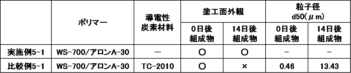
- Example 5-1 and Comparative Example 5-1 When a composite current collector A and a composite current collector B were produced using the thin film forming composition A and the thin film forming composition B immediately after preparation in the above-mentioned Example 1-1 and Comparative example 1-1, respectively, In addition, when the composite current collector A and the composite current collector B are produced using the thin film-forming composition A and the thin film-forming composition B that have been left standing in the air atmosphere at 50° C. for 14 days after the preparation. The coating property was visually evaluated. The evaluation was ⁇ : coating was possible uniformly, x: coating was not possible because some aggregates were observed. The results are shown in Table 3. In addition, the particle size was measured immediately after preparation of the thin film forming composition A and the thin film forming composition B, and after standing at 50° C. in an air atmosphere for 14 days to obtain a median diameter (d 50 ). It was The results are shown in Table 3.
- Example 1-1 since the thin film-forming composition A produced in Example 1-1 does not contain the conductive carbon material, non-uniformity due to aggregation of the conductive carbon material does not occur, and the composition It can be seen that the product itself is stable and has excellent coatability after long-term storage.
Landscapes
- Engineering & Computer Science (AREA)
- Chemical & Material Sciences (AREA)
- Chemical Kinetics & Catalysis (AREA)
- Electrochemistry (AREA)
- General Chemical & Material Sciences (AREA)
- Materials Engineering (AREA)
- Power Engineering (AREA)
- Manufacturing & Machinery (AREA)
- Microelectronics & Electronic Packaging (AREA)
- Battery Electrode And Active Subsutance (AREA)
- Cell Electrode Carriers And Collectors (AREA)
- Electric Double-Layer Capacitors Or The Like (AREA)
Abstract
Description
この要求に応えるための一つの方策として、電極合材層と集電体との間に導電性炭素材料を含むアンダーコート層を配置して、それらの接触界面の抵抗を下げることが提案されている(特許文献1,2参照)が、アンダーコート層の単位面積あたりの重量(目付量)が大きいと、電池が重くなり、また大型化するという問題がある。
しかし、導電性炭素材料以外の成分が多くなると、絶縁性成分が増えるため、アンダーコート層の導電性が低下し、電池の低抵抗化という所期の効果が損なわれるという問題がある。
さらに、これらのアンダーコート層を形成する際に用いる導電性炭素材料を含む分散液は、保存安定性が必ずしも良好ではなく、保存中に導電性炭素材料が凝集する等の問題をしばしば引き起こし、また分散処理自体もコストがかかるため製造費が高額になるという問題があった。
1. 側鎖にオキサゾリン基を有するポリマーおよび溶媒を含み、導電性炭素材料を含まないことを特徴とするエネルギー貯蔵デバイス電極用薄膜形成用組成物、
2. エネルギー貯蔵デバイスの集電体と電極合剤層との間に介在する薄膜形成用である1のエネルギー貯蔵デバイス電極用薄膜形成用組成物、
3. 前記ポリマーが、2位に重合性炭素-炭素二重結合含有基を有するオキサゾリンモノマーと、親水性官能基を有する(メタ)アクリル系モノマーとの少なくとも2種のモノマーのラジカル重合物である1のエネルギー貯蔵デバイス電極用薄膜形成用組成物、
4. 前記ポリマーが、2位に重合性炭素-炭素二重結合含有基を有する式(1)で示されるオキサゾリンモノマーと、(メタ)アクリル酸、アクリル酸2-ヒドロキシエチル、アクリル酸メトキシポリエチレングリコール、アクリル酸とポリエチレングリコールとのモノエステル化物、アクリル酸2-アミノエチルおよびその塩、メタクリル酸2-ヒドロキシエチル、メタクリル酸メトキシポリエチレングリコール、メタクリル酸とポリエチレングリコールとのモノエステル化物、メタクリル酸2-アミノエチルおよびその塩、(メタ)アクリル酸ナトリウム、(メタ)アクリル酸アンモニウム、(メタ)アクリルニトリル、(メタ)アクリルアミド、N-メチロール(メタ)アクリルアミド、並びにN-(2-ヒドロキシエチル)(メタ)アクリルアミドから選ばれる1種または2種以上の親水性官能基を有する(メタ)アクリル系モノマーとのラジカル重合物である3のエネルギー貯蔵デバイス電極用薄膜形成用組成物、
5. 1~4のいずれかのエネルギー貯蔵デバイスのエネルギー貯蔵デバイス電極用薄膜形成用組成物から得られる薄膜を含むアンダーコート層、
6. 5のアンダーコート層を備えるエネルギー貯蔵デバイスの電極用複合集電体、
7. 6のエネルギー貯蔵デバイスの電極用複合集電体を備えるエネルギー貯蔵デバイス用電極、
8. 7のエネルギー貯蔵デバイス用電極を備えるエネルギー貯蔵デバイス、
9. リチウムイオン二次電池である8のエネルギー貯蔵デバイス
を提供する。
また、本発明の組成物は、導電性炭素材料を含まないにもかかわらず、アンダーコート層として機能する薄膜を与える。
本発明に係るエネルギー貯蔵デバイス電極用薄膜形成用組成物(以下、単に組成物という)は、側鎖にオキサゾリン基を有するポリマーおよび溶媒を含み、導電性炭素材料を含まないことを特徴とする。なお、導電性炭素材料とは、カーボンブラック、ケッチェンブラック、アセチレンブラック、カーボンウイスカー、カーボンナノチューブ(CNT)、炭素繊維、天然黒鉛、人造黒鉛等のそれ自身が導電性を有する炭素材料である。

オキサゾリンモノマーが有する重合性炭素-炭素二重結合含有基としては、重合性炭素-炭素二重結合を含んでいれば特に限定されるものではないが、重合性炭素-炭素二重結合を含む鎖状炭化水素基が好ましく、例えば、ビニル基、アリル基、イソプロペニル基等の炭素数2~8のアルケニル基などが好ましい。
ここで、ハロゲン原子としては、フッ素原子、塩素原子、臭素原子、ヨウ素原子が挙げられる。
炭素数1~5のアルキル基としては、直鎖状、分岐鎖状、環状のいずれでもよく、例えば、メチル基、エチル基、n-プロピル基、イソプロピル基、n-ブチル基、sec-ブチル基、tert-ブチル基、n-ペンチル基、シクロヘキシル基等が挙げられる。
炭素数6~20のアリール基の具体例としては、フェニル基、キシリル基、トリル基、ビフェニル基、ナフチル基等が挙げられる。
炭素数7~20のアラルキル基の具体例としては、ベンジル基、フェニルエチル基、フェニルシクロヘキシル基等が挙げられる。
このような水溶性のオキサゾリンポリマーは、上記式(1)で表されるオキサゾリンモノマーのホモポリマーでもよいが、水への溶解性をより高めるため、上記オキサゾリンモノマーと親水性官能基を有する(メタ)アクリル酸エステル系モノマーとの少なくとも2種のモノマーをラジカル重合させて得られたものであることが好ましい。
その他のモノマーの具体例としては、(メタ)アクリル酸メチル、(メタ)アクリル酸エチル、(メタ)アクリル酸ブチル、(メタ)アクリル酸2-エチルヘキシル、(メタ)アクリル酸ステアリル、(メタ)アクリル酸パーフルオロエチル、(メタ)アクリル酸フェニル等の(メタ)アクリル酸エステルモノマー;エチレン、プロピレン、ブテン、ペンテン等のα-オレフィン系モノマー;塩化ビニル、塩化ビニリデン、フッ化ビニル等のハロオレフィン系モノマー;スチレン、α-メチルスチレン等のスチレン系モノマー;酢酸ビニル、プロピオン酸ビニル等のカルボン酸ビニルエステル系モノマー;メチルビニルエーテル、エチルビニルエーテル等のビニルエーテル系モノマーなどが挙げられ、これらはそれぞれ単独で用いても、2種以上組み合わせて用いてもよい。
一方、得られるオキサゾリンポリマーの水溶性をより高めるという点から、モノマー成分における親水性官能基を有する(メタ)アクリル系モノマーの含有率は、10質量%以上が好ましく、20質量%以上がより好ましく、30質量%以上がより一層好ましい。
また、モノマー成分におけるその他の単量体の含有率は、上述のとおり、得られる薄膜の集電体等に対する密着性に影響を与えない範囲であり、また、その種類によって異なるため一概には決定できないが、5~95質量%、好ましくは10~90質量%の範囲で適宜設定すればよい。
また、本発明で使用可能なオキサゾリンポリマーは、市販品として入手することもでき、そのような市販品としては、例えば、エポクロスWS-300((株)日本触媒製、固形分濃度10質量%、水溶液)、エポクロスWS-700((株)日本触媒製、固形分濃度25質量%、水溶液)、エポクロスWS-500((株)日本触媒製、固形分濃度39質量%、水/1-メトキシ-2-プロパノール溶液)、Poly(2-ethyl-2-oxazoline)(Aldrich)、Poly(2-ethyl-2-oxazoline)(AlfaAesar)、Poly(2-ethyl-2-oxazoline)(VWR International,LLC)等が挙げられる。
なお、溶液として市販されている場合、そのまま使用しても、目的とする溶媒に置換してから使用してもよい。
近年、脱有機溶媒化の潮流から溶媒として水を用いた材料が求められていることから、本発明の組成物においても、親水性溶媒と水との混合溶媒や水単独溶媒を用いることが好ましい。
架橋剤としては、オキサゾリンポリマーのオキサゾリン基と架橋反応を起こす化合物、自己架橋する化合物のどちらでもよいが、得られる薄膜の耐溶剤性をより高めるという点から、オキサゾリン基と架橋反応を起こす化合物が好ましい。
オキサゾリン基と架橋反応を起こす化合物の具体例としては、酸触媒の存在下で架橋反応性を発揮する、ポリアクリル酸やそのコポリマー等の合成高分子およびカルボキシメチルセルロースやアルギン酸といった天然高分子の金属塩、加熱により架橋反応性を発揮する、上記合成高分子および天然高分子のアンモニウム塩等が挙げられるが、特に、酸触媒の存在下や加熱条件下で架橋反応性を発揮するポリアクリル酸ナトリウム、ポリアクリル酸リチウム、ポリアクリル酸アンモニウム、カルボキシメチルセルロースナトリウム、カルボキシメチルセルロースリチウム、カルボキシメチルセルロースアンモニウム等が好ましい。
自己架橋する化合物の具体例としては、酸触媒の存在下で架橋反応性を発揮する多官能アクリレート、テトラアルコキシシラン、ブロックイソシアネート基を有するモノマーおよび水酸基、カルボン酸、アミノ基の少なくとも1つを有するモノマーのブロックコポリマーなどが挙げられる。
架橋剤の含有量は、使用する溶媒、使用する基材、要求される粘度や膜形状などにより変動するが、通常、オキサゾリンポリマーに対して0.001~80質量%であり、好ましくは0.01~50質量%、より好ましくは0.05~40質量%である。
なお、本発明の組成物は、架橋反応を促進するための触媒として、p-トルエンスルホン酸、トリフルオロメタンスルホン酸、ピリジニウムp-トルエンスルホン酸、サリチル酸、スルホサリチル酸、クエン酸、安息香酸、ヒドロキシ安息香酸、ナフタレンカルボン酸等の酸性化合物、および/または2,4,4,6-テトラブロモシクロヘキサジエノン、ベンゾイントシレート、2-ニトロベンジルトシレート、有機スルホン酸アルキルエステル等の熱酸発生剤を含んでいてもよい。
触媒の含有量は、導電性炭素材料分散剤(オキサゾリンポリマー)に対して、通常、0.0001~20質量%であり、好ましくは0.0005~10質量%、より好ましくは0.001~3質量%である。
その他の高分子としては、例えば、ポリフッ化ビニリデン(PVdF)、ポリテトラフルオロエチレン、テトラフルオロエチレン-ヘキサフルオロプロピレン共重合体、フッ化ビニリデン-ヘキサフルオロプロピレン共重合体〔P(VDF-HFP)〕、フッ化ビニリデン-塩化3フッ化エチレン共重合体〔P(VDF-CTFE)〕などのフッ素系樹脂、ポリビニルピロリドン、エチレン-プロピレン-ジエン三元共重合体、PE(ポリエチレン)、PP(ポリプロピレン)、EVA(エチレン-酢酸ビニル共重合体)、EEA(エチレン-アクリル酸エチル共重合体)などのポリオレフィン系樹脂;PS(ポリスチレン)、HIPS(ハイインパクトポリスチレン)、AS(アクリロニトリル-スチレン共重合体)、ABS(アクリロニトリル-ブタジエン-スチレン共重合体)、MS(メタクリル酸メチル-スチレン共重合体)、スチレン-ブタジエンゴムなどのポリスチレン系樹脂;ポリカーボネート樹脂;塩化ビニル樹脂;ポリアミド樹脂;ポリイミド樹脂;ポリアクリル酸ナトリウム、PMMA(ポリメチルメタクリレート)などの(メタ)アクリル樹脂;PET(ポリエチレンテレフタレート)、ポリブチレンテレフタレート、ポリエチレンナフタレート、ポリブチレンナフタレート、PLA(ポリ乳酸)、ポリ-3-ヒドロキシ酪酸、ポリカプロラクトン、ポリブチレンサクシネート、ポリエチレンサクシネート/アジペートなどのポリエステル樹脂;ポリフェニレンエーテル樹脂;変性ポリフェニレンエーテル樹脂;ポリアセタール樹脂;ポリスルホン樹脂;ポリフェニレンサルファイド樹脂;ポリビニルアルコール樹脂;ポリグルコール酸;変性でんぷん;酢酸セルロース、カルボキシメチルセルロース、三酢酸セルロース;キチン、キトサン;リグニン等の熱可塑性樹脂や、ポリアニリンおよびその半酸化体であるエメラルジンベース;ポリチオフェン;ポリピロール;ポリフェニレンビニレン;ポリフェニレン;ポリアセチレン等の導電性高分子、さらにはエポキシ樹脂;ウレタンアクリレート;フェノール樹脂;メラミン樹脂;尿素樹脂;アルキド樹脂等の熱硬化性樹脂や光硬化性樹脂などが挙げられるが、本発明の組成物においては、溶媒として水を用いることが好適であることから、その他の高分子としても水溶性のもの、例えば、ポリアクリル酸ナトリウム、カルボキシメチルセルロースナトリウム、水溶性セルロースエーテル、アルギン酸ナトリウム、ポリビニルアルコール、ポリスチレンスルホン酸、ポリエチレングリコール等が挙げられるが、特に、ポリアクリル酸ナトリウム、カルボキシメチルセルロースナトリウム等が好適である。
この際、混合物を分散処理することが好ましい。分散処理としては、機械的処理である、ボールミル、ビーズミル、ジェットミル等を用いる湿式処理や、バス型やプローブ型のソニケータを用いる超音波処理が挙げられるが、特に、ジェットミルを用いた湿式処理や超音波処理が好適である。
分散処理の時間は任意であるが、1分間から10時間程度が好ましく、5分間から5時間程度がより好ましい。この際、必要に応じて加熱処理を施しても構わない。
なお、架橋剤等の任意成分を用いる場合、これらは、オキサゾリンポリマーおよび溶媒からなる混合物を調製した後から加えてもよい。
また、その下限は、任意であるが、実用的な観点から、0.1質量%以上が好ましく、0.5質量%以上がより好ましく、1質量%以上がより一層好ましい。
なお、固形分とは、組成物を構成する溶媒以外の成分の総量である。
したがって、本発明の組成物から得られる薄膜は、エネルギー貯蔵デバイスの電極を構成する集電基板と電極合剤層との間に介在し、両者を結着させる結着層に特に適している。
また、本発明の組成物から得られる薄膜は、導電性炭素材料を含まないにもかかわらず、集電基板と電極合剤層との間の導電性にも影響を与えることがないため、本発明の薄膜は、導電性炭素材料を含む従来のアンダーコート層と同様の機能層として用いることができる。
なお、エネルギー貯蔵デバイスとしては、電気二重層キャパシタ、リチウム二次電池、リチウムイオン二次電池、プロトンポリマー電池、ニッケル水素電池、アルミ固体コンデンサ、電解コンデンサ、鉛蓄電池等の各種エネルギー貯蔵デバイスが挙げられるが、本発明の導電性薄膜用組成物から得られる導電性薄膜は、特に、電気二重層キャパシタ、リチウムイオン二次電池の電極に好適に適用することができる。
この複合集電体は、集電体上に、上述した組成物を塗布し、これを自然または加熱乾燥し、薄膜を形成して作製することができる。
集電体は、従来、エネルギー貯蔵デバイス用電極の集電体として用いられているものを使用することができる。例えば、銅、アルミニウム、チタン、ステンレス、ニッケル、金、銀およびこれらの合金や、カーボン材料、金属酸化物、導電性高分子等を用いることができるが、超音波溶接等の溶接を適用して電極構造体を作製する場合、銅、アルミニウム、チタン、ステンレスまたはこれらの合金からなる金属箔を用いることが好ましい。
集電体の厚みは特に限定されないが、本発明においては、1~100μmが好ましい。
また、薄膜の厚みも、特に限定されるものではないが、内部抵抗を低減することを考慮すると、1nm~10μmが好ましく、1nm~1μmがより好ましく、1~500nmがより一層好ましい。
薄膜の膜厚は、公知の方法で調整することができる。例えば、塗布により薄膜を形成する場合、組成物の固形分濃度、塗布回数、塗工機の塗工液投入口のクリアランスなどを変えることで調整できる。
膜厚を厚くしたい場合は、固形分濃度を高くしたり、塗布回数を増やしたり、クリアランスを大きくしたりする。膜厚を薄くしたい場合は、固形分濃度を低くしたり、塗布回数を減らしたり、クリアランスを小さくしたりする。
加熱乾燥する場合の温度も任意であるが、50~200℃程度が好ましく、80~150℃程度がより好ましい。
ここで、活物質としては、従来、エネルギー貯蔵デバイス用電極に用いられている各種活物質を用いることができる。
例えば、リチウム二次電池やリチウムイオン二次電池の場合、正極活物質としてリチウムイオンを吸着・離脱可能なカルコゲン化合物またはリチウムイオン含有カルコゲン化合物、ポリアニオン系化合物、硫黄単体およびその化合物等を用いることができる。
このようなリチウムイオンを吸着離脱可能なカルコゲン化合物としては、例えばFeS2、TiS2、MoS2、V2O6、V6O13、MnO2等が挙げられる。
リチウムイオン含有カルコゲン化合物としては、例えばLiCoO2、LiMnO2、LiMn2O4、LiMo2O4、LiV3O8、LiNiO2、LixNiyM1-yO2(但し、Mは、Co、Mn、Ti、Cr、V、Al、Sn、Pb、およびZnから選ばれる少なくとも1種以上の金属元素を表し、0.05≦x≦1.10、0.5≦y≦1.0)等が挙げられる。
ポリアニオン系化合物としては、例えばLiFePO4等が挙げられる。
硫黄化合物としては、例えばLi2S、ルベアン酸等が挙げられる。
アルカリ金属としては、Li、Na、K等が挙げられ、アルカリ金属合金としては、例えば、Li-Al、Li-Mg、Li-Al-Ni、Na-Hg、Na-Zn等が挙げられる。
リチウムイオンを吸蔵放出する周期表4~15族の元素から選ばれる少なくとも1種の元素の単体としては、例えば、ケイ素やスズ、アルミニウム、亜鉛、砒素等が挙げられる。
同じく酸化物としては、例えば、スズケイ素酸化物(SnSiO3)、リチウム酸化ビスマス(Li3BiO4)、リチウム酸化亜鉛(Li2ZnO2)、リチウム酸化チタン(Li4Ti5O12)、酸化チタン等が挙げられる。
同じく硫化物としては、リチウム硫化鉄(LixFeS2(0≦x≦3))、リチウム硫化銅(LixCuS(0≦x≦3))等が挙げられる。
同じく窒化物としては、リチウム含有遷移金属窒化物が挙げられ、具体的には、LixMyN(M=Co、Ni、Cu、0≦x≦3、0≦y≦0.5)、リチウム鉄窒化物(Li3FeN4)等が挙げられる。
リチウムイオンを可逆的に吸蔵・放出可能な炭素材料としては、グラファイト、カーボンブラック、コークス、ガラス状炭素、炭素繊維、カーボンナノチューブ、またはこれらの焼結体等が挙げられる。
この炭素質材料としては、活性炭等が挙げられ、例えば、フェノール樹脂を炭化後、賦活処理して得られた活性炭が挙げられる。
なお、バインダーポリマーの添加量は、活物質100質量部に対して、0.1~20質量部、特に、1~10質量部が好ましい。
溶媒としては、上記組成物用の溶媒で例示した溶媒が挙げられ、それらの中からバインダーの種類に応じて適宜選択すればよいが、PVdF等の非水溶性のバインダーの場合はNMPが好適であり、PAA等の水溶性のバインダーの場合は水が好適である。
また、加熱乾燥する場合の温度も任意であるが、50~400℃程度が好ましく、80~150℃程度がより好ましい。
このエネルギー貯蔵デバイスは、電極として上述したエネルギー貯蔵デバイス用電極を用いることにその特徴があるため、その他のデバイス構成部材であるセパレータや、電解質などは、公知の材料から適宜選択して用いることができる。
セパレータとしては、例えば、セルロース系セパレータ、ポリオレフィン系セパレータ等が挙げられる。
電解質としては、液体、固体のいずれでもよく、また水系、非水系のいずれでもよいが、本発明のエネルギー貯蔵デバイス用電極は、非水系電解質を用いたデバイスに適用した場合にも実用上十分な性能を発揮させ得る。
電解質塩としては、4フッ化硼酸リチウム、6フッ化リン酸リチウム、過塩素酸リチウム、トリフルオロメタンスルホン酸リチウム等のリチウム塩;テトラメチルアンモニウムヘキサフルオロホスフェート、テトラエチルアンモニウムヘキサフルオロホスフェート、テトラプロピルアンモニウムヘキサフルオロホスフェート、メチルトリエチルアンモニウムヘキサフルオロホスフェート、テトラエチルアンモニウムテトラフルオロボレート、テトラエチルアンモニウムパークロレート等の4級アンモニウム塩、リチウムビス(トリフルオロメタンスルホニル)イミド、リチウムビス(フルオロスルホニル)イミド等のリチウムイミドなどが挙げられる。
非水系有機溶媒としては、プロピレンカーボネート、エチレンカーボネート、ブチレンカーボネート等のアルキレンカーボネート;ジメチルカーボネート、メチルエチルカーボネート、ジエチルカーボネート等のジアルキルカーボネート;アセトニトリル等のニトリル類、ジメチルホルムアミド等のアミド類などが挙げられる。
コイン型に適用する場合、上述した本発明のエネルギー貯蔵デバイス用電極を、所定の円盤状に打ち抜いて用いればよい。
例えば、リチウムイオン二次電池は、コインセルのワッシャーとスペーサーが溶接されたフタに、一方の電極を設置し、その上に、電解液を含浸させた同形状のセパレータを重ね、さらに上から、電極合材層を下にして本発明のエネルギー貯蔵デバイス用電極を重ね、ケースとガスケットを載せて、コインセルかしめ機で密封して作製することができる。
この場合、電極構造体を構成する電極は一枚でも複数枚でもよいが、一般的には、正負極とも複数枚が用いられる。
正極を形成するための複数枚の電極は、負極を形成するための複数枚の電極と、一枚ずつ交互に重ねることが好ましく、その際、正極と負極の間には上述したセパレータを介在させることが好ましい。
金属タブは、複数枚の電極の最も外側の電極の溶接部で溶接しても、複数枚の電極のうち、任意の隣接する2枚の電極の溶接部間に金属タブを挟んで溶接してもよい。
金属タブの形状は、箔状が好ましく、その厚さは0.05~1mm程度が好ましい。
超音波溶接の手法としては、例えば、複数枚の電極をアンビルとホーンとの間に配置し、溶接部に金属タブを配置して超音波をかけて一括して溶接する手法や、電極同士を先に溶接し、その後、金属タブを溶接する手法などが挙げられる。
本発明では、いずれの手法でも、金属タブと電極とが上記溶接部で溶接されるだけでなく、複数枚の電極同士も互いに超音波溶接されることになる。
溶接時の圧力、周波数、出力、処理時間等は、特に限定されるものではなく、用いる材料やアンダーコート層の有無、目付量などを考慮して適宜設定すればよい。
以上のようにして作製した電極構造体を、ラミネートパックに収納し、上述した電解液を注入した後、ヒートシールすることでラミネートセルが得られる。
(1)プローブ型超音波照射装置
Hielscher Ultrasonics社製、UIP1000
(2)ワイヤーバーコーター(アンダーコート層形成)
(株)エスエムテー製、PM-9050MC
(3)ホモディスパー(電極スラリーの混合)
プライミクス(株)製、T.K.ロボミックス(ホモディスパー2.5型(φ32)付き)
(4)ビーズミル(電極スラリーの混合)
三菱電機(株)製、FREQROL-E500
(5)自転・公転ミキサー(電極スラリーの脱泡)
(株)シンキー製、あわとり練太郎(ARE-310)
(6)ロールプレス機(電極の圧縮)
有限会社タクミ技研製、SA-602
(7)充放電測定装置(二次電池評価)
東洋システム(株)製、TOSCAT-3100
(8)コインセルかしめ機
宝泉(株)製、手動コインカシメ機CR2032
[実施例1-1]
オキサゾリンポリマーを含む水溶液であるWS-700(日本触媒(株)製、固形分濃度:25.0質量%)6.94gと、ポリアクリル酸アンモニウムを含む水溶液であるアロンA-30(東亞合成(株)製、固形分濃度:31.6質量%)2.42gと、純水40.64gとを混合し、均一な溶液である薄膜形成用組成物Aを調製した。
オキサゾリンポリマーを含む水溶液であるWS-700(日本触媒(株)製、固形分濃度:25.0質量%)2.00gと、純水40.15gと、2-プロパノール(純正化学(株)製、試薬特級)7.35gとを混合し、さらにそこへ導電性炭素材料であるTC-2010(戸田工業(株)製、多層CNT)0.50gを混合した。得られた混合物に対して、プローブ型超音波照射装置を用いて30分間超音波処理を行い、均一に導電性炭素材料が分散した分散液を調製した。これに、ポリアクリル酸アンモニウム(PAA-NH4)を含む水溶液であるアロンA-30(東亞合成(株)製、固形分濃度:31.6質量%)0.70gと、純水41.84gと、2-プロパノール(純正化学(株)製、試薬特級)7.47gとを混合して、均一なCNT分散液である薄膜形成用組成物Bを調製した。
[実施例2-1]
実施例1-1で調製した薄膜形成用組成物Aを、集電体である銅箔(厚さ15μm)にワイヤーバーコーターで均一に展開後、110℃で20分乾燥してアンダーコート層を形成し、複合集電体Aを作製した。目付量を測定した結果、50mg/m2であった。
薄膜形成用組成物Aを比較例1-1で調製した薄膜形成用組成物Bに変更した以外は、実施例2-1と同様の方法で複合集電体Bを作製した。目付量を測定した結果、47mg/m2であった。
[実施例3-1]
活物質としてシリコン(日本NER(株)製)13.5g、バインダーとしてポリアクリル酸(PAA、富士フイルム和光純薬(株)製)3.6g、導電助剤としてアセチレンブラック(AB、デンカ(株)製)0.9gおよび水42.0gを、ホモディスパーにて3,000rpmで5分間混合した。次いで、ビーズミルを用いて2,000rpmで30分の混合処理をし、さらに自転・公転ミキサーにて1,000rpmで2分脱泡して電極スラリー(固形分濃度30質量%、シリコン:PAA:AB=75:20:5(質量比))を作製した。得られた電極スラリーを、実施例2-1で作製した複合集電体Aに展開後、80℃で30分、次いで120℃で30分乾燥してアンダーコート層上に活物質層を形成し、さらにロールプレス機で1.2kN/cmのプレス圧で圧着することで電極Aを作製した。
複合集電体Aを比較例2-1で作製した複合集電体Bに変更した以外は、実施例3-1と同様の方法で、電極Bを作製した。
複合集電体Aを無垢の銅箔に変更した以外は、実施例3-1と同様の方法で、電極Cを作製した。

[実施例4-1]
活物質として一酸化珪素(SiO、(株)大阪チタニウムテクノロジーズ製)2.16g、黒鉛(SNO-10、SECカーボン(株)製)5.04g、バインダーとしてポリアクリル酸リチウム(PAALi)0.23g、導電助剤としてアセチレンブラック(AB、デンカ(株)製)0.39gおよび水11.69gを、自転・公転ミキサーで混合処理して電極スラリー(固形分濃度40質量%、SiO:SNO-10:PAALi:AB=27.6:64.4:3.0:5.0(質量比))を作製した。得られた電極スラリーを、複合集電体Aに展開後、80℃で30分乾燥してアンダーコート層上に活物質層を形成し、さらにロールプレス機で0.1kN/cmのプレス圧で圧着して電極Dを作製した。
複合集電体Aを複合集電体Bに変更した以外は、実施例4-1と同様の方法で、電極Eを作製した。
複合集電体Aを無垢の銅箔に変更した以外は、実施例4-1と同様の方法で、電極Fを作製した。

・試験電池数:3個
・温度:室温
・定電圧充電は各レートの1/10でカット
[実施例5-1、比較例5-1]
上記実施例1-1および比較例1-1で調製した直後の薄膜形成用組成物Aおよび薄膜形成用組成物Bを用いて複合集電体Aおよび複合集電体Bをそれぞれ作製した場合、並びに調製後、50℃、大気雰囲気下で14日間静置した後の薄膜形成用組成物Aおよび薄膜形成用組成物Bを用いて複合集電体Aおよび複合集電体Bをそれぞれ作製した場合について、塗工性を目視で評価した。評価は、〇:均一に塗工可、×:一部凝集物が見られるため塗工不可とした。結果を表3に示す。
また、薄膜形成用組成物Aおよび薄膜形成用組成物Bの作製直後、並びに50℃、大気雰囲気下で14日間静置した後のそれぞれについて粒子径測定を行い、メディアン径(d50)を求めた。結果を表3に示す。
Claims (9)
- 側鎖にオキサゾリン基を有するポリマーおよび溶媒を含み、導電性炭素材料を含まないことを特徴とするエネルギー貯蔵デバイス電極用薄膜形成用組成物。
- エネルギー貯蔵デバイスの集電体と電極合剤層との間に介在する薄膜形成用である請求項1記載のエネルギー貯蔵デバイス電極用薄膜形成用組成物。
- 前記ポリマーが、2位に重合性炭素-炭素二重結合含有基を有するオキサゾリンモノマーと、親水性官能基を有する(メタ)アクリル系モノマーとの少なくとも2種のモノマーのラジカル重合物である請求項1記載のエネルギー貯蔵デバイス電極用薄膜形成用組成物。
- 前記ポリマーが、2位に重合性炭素-炭素二重結合含有基を有する式(1)で示されるオキサゾリンモノマーと、(メタ)アクリル酸、アクリル酸2-ヒドロキシエチル、アクリル酸メトキシポリエチレングリコール、アクリル酸とポリエチレングリコールとのモノエステル化物、アクリル酸2-アミノエチルおよびその塩、メタクリル酸2-ヒドロキシエチル、メタクリル酸メトキシポリエチレングリコール、メタクリル酸とポリエチレングリコールとのモノエステル化物、メタクリル酸2-アミノエチルおよびその塩、(メタ)アクリル酸ナトリウム、(メタ)アクリル酸アンモニウム、(メタ)アクリルニトリル、(メタ)アクリルアミド、N-メチロール(メタ)アクリルアミド、並びにN-(2-ヒドロキシエチル)(メタ)アクリルアミドから選ばれる1種または2種以上の親水性官能基を有する(メタ)アクリル系モノマーとのラジカル重合物である請求項3記載のエネルギー貯蔵デバイス電極用薄膜形成用組成物。

- 請求項1~4のいずれか1項記載のエネルギー貯蔵デバイスのエネルギー貯蔵デバイス電極用薄膜形成用組成物から得られる薄膜を含むアンダーコート層。
- 請求項5記載のアンダーコート層を備えるエネルギー貯蔵デバイスの電極用複合集電体。
- 請求項6記載のエネルギー貯蔵デバイスの電極用複合集電体を備えるエネルギー貯蔵デバイス用電極。
- 請求項7記載のエネルギー貯蔵デバイス用電極を備えるエネルギー貯蔵デバイス。
- リチウムイオン二次電池である請求項8記載のエネルギー貯蔵デバイス。
Priority Applications (2)
| Application Number | Priority Date | Filing Date | Title |
|---|---|---|---|
| JP2021501935A JP7559746B2 (ja) | 2019-02-21 | 2020-02-14 | エネルギー貯蔵デバイス電極用薄膜形成用組成物 |
| KR1020217029162A KR102871644B1 (ko) | 2019-02-21 | 2020-02-14 | 에너지 저장 디바이스 전극용 박막 형성용 조성물 |
Applications Claiming Priority (2)
| Application Number | Priority Date | Filing Date | Title |
|---|---|---|---|
| JP2019-029126 | 2019-02-21 | ||
| JP2019029126 | 2019-02-21 |
Publications (1)
| Publication Number | Publication Date |
|---|---|
| WO2020170960A1 true WO2020170960A1 (ja) | 2020-08-27 |
Family
ID=72145071
Family Applications (1)
| Application Number | Title | Priority Date | Filing Date |
|---|---|---|---|
| PCT/JP2020/005781 Ceased WO2020170960A1 (ja) | 2019-02-21 | 2020-02-14 | エネルギー貯蔵デバイス電極用薄膜形成用組成物 |
Country Status (3)
| Country | Link |
|---|---|
| JP (1) | JP7559746B2 (ja) |
| KR (1) | KR102871644B1 (ja) |
| WO (1) | WO2020170960A1 (ja) |
Cited By (2)
| Publication number | Priority date | Publication date | Assignee | Title |
|---|---|---|---|---|
| WO2023054367A1 (ja) * | 2021-09-30 | 2023-04-06 | 日産化学株式会社 | 電極形成用組成物 |
| EP4567919A1 (en) * | 2023-12-06 | 2025-06-11 | Samsung Sdi Co., Ltd. | Electrodes of rechargeable lithium batteries and rechargeable lithium batteries |
Citations (3)
| Publication number | Priority date | Publication date | Assignee | Title |
|---|---|---|---|---|
| WO2012133030A1 (ja) * | 2011-03-31 | 2012-10-04 | 東洋インキScホールディングス株式会社 | 二次電池電極形成用水性組成物、二次電池用電極、及び二次電池 |
| WO2015029949A1 (ja) * | 2013-08-27 | 2015-03-05 | 日産化学工業株式会社 | 導電性炭素材料分散剤および導電性炭素材料分散液 |
| WO2017119288A1 (ja) * | 2016-01-07 | 2017-07-13 | 日産化学工業株式会社 | エネルギー貯蔵デバイス用電極 |
Family Cites Families (3)
| Publication number | Priority date | Publication date | Assignee | Title |
|---|---|---|---|---|
| JP4487220B1 (ja) | 2009-01-26 | 2010-06-23 | トヨタ自動車株式会社 | リチウム二次電池用正極およびその製造方法 |
| CN104620429A (zh) | 2012-09-14 | 2015-05-13 | 日产化学工业株式会社 | 用于储能器件电极的复合集电体和电极 |
| JP2016072147A (ja) | 2014-09-30 | 2016-05-09 | 株式会社日本触媒 | 電池用電極スラリー用組成物 |
-
2020
- 2020-02-14 KR KR1020217029162A patent/KR102871644B1/ko active Active
- 2020-02-14 WO PCT/JP2020/005781 patent/WO2020170960A1/ja not_active Ceased
- 2020-02-14 JP JP2021501935A patent/JP7559746B2/ja active Active
Patent Citations (3)
| Publication number | Priority date | Publication date | Assignee | Title |
|---|---|---|---|---|
| WO2012133030A1 (ja) * | 2011-03-31 | 2012-10-04 | 東洋インキScホールディングス株式会社 | 二次電池電極形成用水性組成物、二次電池用電極、及び二次電池 |
| WO2015029949A1 (ja) * | 2013-08-27 | 2015-03-05 | 日産化学工業株式会社 | 導電性炭素材料分散剤および導電性炭素材料分散液 |
| WO2017119288A1 (ja) * | 2016-01-07 | 2017-07-13 | 日産化学工業株式会社 | エネルギー貯蔵デバイス用電極 |
Cited By (3)
| Publication number | Priority date | Publication date | Assignee | Title |
|---|---|---|---|---|
| WO2023054367A1 (ja) * | 2021-09-30 | 2023-04-06 | 日産化学株式会社 | 電極形成用組成物 |
| EP4567919A1 (en) * | 2023-12-06 | 2025-06-11 | Samsung Sdi Co., Ltd. | Electrodes of rechargeable lithium batteries and rechargeable lithium batteries |
| JP2025091402A (ja) * | 2023-12-06 | 2025-06-18 | 三星エスディアイ株式会社 | リチウム二次電池用電極およびこれを含むリチウム二次電池 |
Also Published As
| Publication number | Publication date |
|---|---|
| KR102871644B1 (ko) | 2025-10-17 |
| KR20210130176A (ko) | 2021-10-29 |
| JPWO2020170960A1 (ja) | 2021-12-16 |
| JP7559746B2 (ja) | 2024-10-02 |
Similar Documents
| Publication | Publication Date | Title |
|---|---|---|
| JP6962200B2 (ja) | エネルギー貯蔵デバイス用電極 | |
| JP7035496B2 (ja) | エネルギー貯蔵デバイス電極用アンダーコート箔 | |
| JP5773097B1 (ja) | 導電性結着層用組成物 | |
| EP3401982B1 (en) | Electrode for energy storage devices | |
| JP6531868B2 (ja) | エネルギー貯蔵デバイス電極およびエネルギー貯蔵デバイス | |
| JP7110986B2 (ja) | 導電性組成物 | |
| JP7559746B2 (ja) | エネルギー貯蔵デバイス電極用薄膜形成用組成物 | |
| JPWO2020040078A1 (ja) | エネルギー貯蔵デバイス電極用薄膜形成用組成物、エネルギー貯蔵デバイス電極用複合集電体、エネルギー貯蔵デバイス電極、及びエネルギー貯蔵デバイス |
Legal Events
| Date | Code | Title | Description |
|---|---|---|---|
| 121 | Ep: the epo has been informed by wipo that ep was designated in this application |
Ref document number: 20758433 Country of ref document: EP Kind code of ref document: A1 |
|
| ENP | Entry into the national phase |
Ref document number: 2021501935 Country of ref document: JP Kind code of ref document: A |
|
| NENP | Non-entry into the national phase |
Ref country code: DE |
|
| ENP | Entry into the national phase |
Ref document number: 20217029162 Country of ref document: KR Kind code of ref document: A |
|
| 122 | Ep: pct application non-entry in european phase |
Ref document number: 20758433 Country of ref document: EP Kind code of ref document: A1 |