WO2020170678A1 - 車両用センシングシステム及び車両 - Google Patents
車両用センシングシステム及び車両 Download PDFInfo
- Publication number
- WO2020170678A1 WO2020170678A1 PCT/JP2020/001731 JP2020001731W WO2020170678A1 WO 2020170678 A1 WO2020170678 A1 WO 2020170678A1 JP 2020001731 W JP2020001731 W JP 2020001731W WO 2020170678 A1 WO2020170678 A1 WO 2020170678A1
- Authority
- WO
- WIPO (PCT)
- Prior art keywords
- vehicle
- lidar unit
- lidar
- sensing system
- unit
- Prior art date
- Legal status (The legal status is an assumption and is not a legal conclusion. Google has not performed a legal analysis and makes no representation as to the accuracy of the status listed.)
- Ceased
Links
Images


Classifications
-
- G—PHYSICS
- G01—MEASURING; TESTING
- G01S—RADIO DIRECTION-FINDING; RADIO NAVIGATION; DETERMINING DISTANCE OR VELOCITY BY USE OF RADIO WAVES; LOCATING OR PRESENCE-DETECTING BY USE OF THE REFLECTION OR RERADIATION OF RADIO WAVES; ANALOGOUS ARRANGEMENTS USING OTHER WAVES
- G01S17/00—Systems using the reflection or reradiation of electromagnetic waves other than radio waves, e.g. lidar systems
- G01S17/88—Lidar systems specially adapted for specific applications
- G01S17/89—Lidar systems specially adapted for specific applications for mapping or imaging
-
- G—PHYSICS
- G01—MEASURING; TESTING
- G01S—RADIO DIRECTION-FINDING; RADIO NAVIGATION; DETERMINING DISTANCE OR VELOCITY BY USE OF RADIO WAVES; LOCATING OR PRESENCE-DETECTING BY USE OF THE REFLECTION OR RERADIATION OF RADIO WAVES; ANALOGOUS ARRANGEMENTS USING OTHER WAVES
- G01S17/00—Systems using the reflection or reradiation of electromagnetic waves other than radio waves, e.g. lidar systems
- G01S17/88—Lidar systems specially adapted for specific applications
- G01S17/93—Lidar systems specially adapted for specific applications for anti-collision purposes
- G01S17/931—Lidar systems specially adapted for specific applications for anti-collision purposes of land vehicles
-
- G—PHYSICS
- G01—MEASURING; TESTING
- G01B—MEASURING LENGTH, THICKNESS OR SIMILAR LINEAR DIMENSIONS; MEASURING ANGLES; MEASURING AREAS; MEASURING IRREGULARITIES OF SURFACES OR CONTOURS
- G01B11/00—Measuring arrangements characterised by the use of optical techniques
-
- G—PHYSICS
- G01—MEASURING; TESTING
- G01S—RADIO DIRECTION-FINDING; RADIO NAVIGATION; DETERMINING DISTANCE OR VELOCITY BY USE OF RADIO WAVES; LOCATING OR PRESENCE-DETECTING BY USE OF THE REFLECTION OR RERADIATION OF RADIO WAVES; ANALOGOUS ARRANGEMENTS USING OTHER WAVES
- G01S17/00—Systems using the reflection or reradiation of electromagnetic waves other than radio waves, e.g. lidar systems
- G01S17/86—Combinations of lidar systems with systems other than lidar, radar or sonar, e.g. with direction finders
-
- G—PHYSICS
- G08—SIGNALLING
- G08G—TRAFFIC CONTROL SYSTEMS
- G08G1/00—Traffic control systems for road vehicles
- G08G1/16—Anti-collision systems
-
- B—PERFORMING OPERATIONS; TRANSPORTING
- B60—VEHICLES IN GENERAL
- B60R—VEHICLES, VEHICLE FITTINGS, OR VEHICLE PARTS, NOT OTHERWISE PROVIDED FOR
- B60R11/00—Arrangements for holding or mounting articles, not otherwise provided for
- B60R11/04—Mounting of cameras operative during drive; Arrangement of controls thereof relative to the vehicle
-
- B—PERFORMING OPERATIONS; TRANSPORTING
- B60—VEHICLES IN GENERAL
- B60R—VEHICLES, VEHICLE FITTINGS, OR VEHICLE PARTS, NOT OTHERWISE PROVIDED FOR
- B60R11/00—Arrangements for holding or mounting articles, not otherwise provided for
- B60R2011/0001—Arrangements for holding or mounting articles, not otherwise provided for characterised by position
- B60R2011/004—Arrangements for holding or mounting articles, not otherwise provided for characterised by position outside the vehicle
-
- G—PHYSICS
- G01—MEASURING; TESTING
- G01S—RADIO DIRECTION-FINDING; RADIO NAVIGATION; DETERMINING DISTANCE OR VELOCITY BY USE OF RADIO WAVES; LOCATING OR PRESENCE-DETECTING BY USE OF THE REFLECTION OR RERADIATION OF RADIO WAVES; ANALOGOUS ARRANGEMENTS USING OTHER WAVES
- G01S13/00—Systems using the reflection or reradiation of radio waves, e.g. radar systems; Analogous systems using reflection or reradiation of waves whose nature or wavelength is irrelevant or unspecified
- G01S13/88—Radar or analogous systems specially adapted for specific applications
- G01S13/93—Radar or analogous systems specially adapted for specific applications for anti-collision purposes
- G01S13/931—Radar or analogous systems specially adapted for specific applications for anti-collision purposes of land vehicles
- G01S2013/9315—Monitoring blind spots
-
- G—PHYSICS
- G01—MEASURING; TESTING
- G01S—RADIO DIRECTION-FINDING; RADIO NAVIGATION; DETERMINING DISTANCE OR VELOCITY BY USE OF RADIO WAVES; LOCATING OR PRESENCE-DETECTING BY USE OF THE REFLECTION OR RERADIATION OF RADIO WAVES; ANALOGOUS ARRANGEMENTS USING OTHER WAVES
- G01S13/00—Systems using the reflection or reradiation of radio waves, e.g. radar systems; Analogous systems using reflection or reradiation of waves whose nature or wavelength is irrelevant or unspecified
- G01S13/88—Radar or analogous systems specially adapted for specific applications
- G01S13/93—Radar or analogous systems specially adapted for specific applications for anti-collision purposes
- G01S13/931—Radar or analogous systems specially adapted for specific applications for anti-collision purposes of land vehicles
- G01S2013/9327—Sensor installation details
- G01S2013/93271—Sensor installation details in the front of the vehicles
-
- G—PHYSICS
- G01—MEASURING; TESTING
- G01S—RADIO DIRECTION-FINDING; RADIO NAVIGATION; DETERMINING DISTANCE OR VELOCITY BY USE OF RADIO WAVES; LOCATING OR PRESENCE-DETECTING BY USE OF THE REFLECTION OR RERADIATION OF RADIO WAVES; ANALOGOUS ARRANGEMENTS USING OTHER WAVES
- G01S13/00—Systems using the reflection or reradiation of radio waves, e.g. radar systems; Analogous systems using reflection or reradiation of waves whose nature or wavelength is irrelevant or unspecified
- G01S13/88—Radar or analogous systems specially adapted for specific applications
- G01S13/93—Radar or analogous systems specially adapted for specific applications for anti-collision purposes
- G01S13/931—Radar or analogous systems specially adapted for specific applications for anti-collision purposes of land vehicles
- G01S2013/9327—Sensor installation details
- G01S2013/93272—Sensor installation details in the back of the vehicles
Definitions
- the present disclosure relates to a vehicle sensing system and a vehicle.
- the vehicle system automatically controls the traveling of the vehicle. Specifically, in the automatic driving mode, the vehicle system performs steering control based on information (surrounding environment information) indicating the surrounding environment of the vehicle obtained from sensors such as cameras and radars (for example, laser radar and millimeter wave radar). At least one of (control of traveling direction of vehicle), brake control and accelerator control (control of vehicle braking, acceleration/deceleration) is automatically performed.
- the driver controls the traveling of the vehicle, as is the case with most conventional vehicles.
- the traveling of the vehicle is controlled in accordance with the driver's operation (steering operation, braking operation, accelerator operation), and the vehicle system does not automatically perform steering control, brake control and accelerator control.
- the driving mode of the vehicle is not a concept that exists only in some vehicles, but a concept that exists in all vehicles including conventional vehicles that do not have an automatic driving function. It is classified according to the method.
- Patent Document 1 discloses an automatic following system in which a following vehicle automatically follows a preceding vehicle.
- each of the preceding vehicle and the following vehicle is provided with an illumination system, and character information for preventing another vehicle from interrupting between the preceding vehicle and the following vehicle is added to the illumination system of the preceding vehicle.
- the character information indicating that the vehicle is automatically following is displayed on the illumination system of the following vehicle.
- the plurality of sensors do not affect the shadow of other vehicles existing in the vicinity of the vehicle. It is not possible to detect objects such as pedestrians and motorcycles hidden behind. For example, it is assumed that a pedestrian who is hidden behind another vehicle suddenly jumps out in front of the own vehicle. Even in such a situation, the self-driving vehicle needs to instantly determine the optimum vehicle control according to the behavior of the pedestrian.
- the present disclosure aims to provide a vehicle sensing system and a vehicle that can detect an object hidden behind another vehicle.
- a vehicular sensing system is provided in a vehicle, is disposed on a back surface of a vehicle body that faces a road, and is configured to acquire point cloud data indicating a surrounding environment of the vehicle. It comprises at least one LiDAR unit.
- the LiDAR unit since the LiDAR unit is arranged on the back surface of the vehicle body, the LiDAR unit targets objects such as pedestrians and other vehicles existing around the vehicle through the space between the back surface of the vehicle body and the road. It becomes possible to detect. Therefore, the LiDAR unit can detect objects such as pedestrians and motorcycles hidden behind other vehicles through the space between the back surface of the body of the other vehicle and the road.
- the vehicle sensing system further includes at least one camera that is arranged at a predetermined position of the vehicle body other than the back surface of the vehicle body and that is configured to acquire image data indicating the surrounding environment of the vehicle. Good.
- the surrounding environment of the vehicle which cannot be detected by the LiDAR unit, can be detected by the camera arranged at a predetermined position on the vehicle body other than the back surface of the vehicle body.
- the camera arranged at a predetermined position on the vehicle body other than the back surface of the vehicle body.
- the vehicle sensing system may further include a LiDAR control unit configured to acquire the surrounding environment information of the vehicle based on the point cloud data acquired from the LiDAR unit.
- the LiDAR control unit may be configured to delete information about the vehicle tire from the surrounding environment information.
- the information regarding the tire of the vehicle is deleted from the surrounding environment information, so that it is possible to prevent the situation where the tire is detected as an object existing around the vehicle.
- the at least one LiDAR unit comprises A front LiDAR unit arranged near the rear ends of a pair of front tires of the vehicle in the front-rear direction of the vehicle, and arranged near the center of the vehicle in the left-right direction of the vehicle;
- a rear LiDAR unit may be arranged near the rear ends of a pair of rear tires of the vehicle in the front-rear direction and near the center of the vehicle in the left-right direction.
- a vehicle equipped with a vehicle sensing system may be provided.
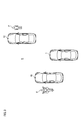
- FIG. 1A is a plan view of a vehicle according to an embodiment of the present invention (hereinafter, simply referred to as the present embodiment) viewed from above.
- (B) is a plan view of the vehicle according to the present embodiment as seen from below. It is a block diagram showing a vehicle system concerning this embodiment. It is a figure which shows the pedestrian and the motorcycle which exist in the blind spot of the vehicle which concerns on this embodiment.
- lateral direction”, “vertical direction”, and “front-back direction” may be referred to as appropriate. These directions are the relative directions set for the vehicle 1 shown in FIG.
- the “left-right direction” is a direction including the “left direction” and the “right direction”.
- “Up-down direction” is a direction that includes “upward” and “downward”.
- the “front-rear direction” is a direction including the “front direction” and the “rear direction”.
- the up-down direction is a direction orthogonal to the left-right direction and the front-back direction.
- FIG. 1A is a plan view of the vehicle 1 viewed from above.
- FIG. 1B is a plan view of the vehicle 1 viewed from below.
- FIG. 2 is a block diagram showing the vehicle system 2 of the vehicle 1.
- the vehicle 1 is a vehicle (automobile) capable of traveling in an automatic driving mode, and includes a vehicle system 2.
- the vehicle system 2 includes a vehicle control unit 3, a front camera 4, a rear camera 5, a front LiDAR (Light Detection and Ranging) unit 6, and a rear LiDAR unit 7.
- the vehicle system 2 also includes a sensor 18, an HMI (Human Machine Interface) 8, a GPS (Global Positioning System) 9, a wireless communication unit 10, and a storage device 11.
- the vehicle system 2 includes a steering actuator 12, a steering device 13, a brake actuator 14, a brake device 15, an accelerator actuator 16, and an accelerator device 17.
- the front camera 4, the rear camera 5, the front LiDAR unit 6, the rear LiDAR unit 7, and the vehicle control unit 3 configure the vehicle sensing system 20 (hereinafter, simply referred to as “sensing system”). ) Is configured. In this way, the sensing system 20 has the sensing function of the vehicle system 2.
- the vehicle control unit 3 is configured to control the traveling of the vehicle 1.
- the vehicle control unit 3 is composed of, for example, at least one electronic control unit (ECU: Electronic Control Unit).
- the electronic control unit includes a computer system (for example, SoC (System on a Chip)) including one or more processors and one or more memories, and an electronic circuit including active elements such as transistors and passive elements.
- the processor includes, for example, at least one of a CPU (Central Processing Unit), an MPU (Micro Processing Unit), a GPU (Graphics Processing Unit), and a TPU (Tensor Processing Unit).
- the CPU may be composed of a plurality of CPU cores.
- the GPU may be composed of a plurality of GPU cores.
- the memory includes a ROM (Read Only Memory) and a RAM (Random Access Memory).
- a vehicle control program may be stored in the ROM.
- the vehicle control program may include an artificial intelligence (AI) program for autonomous driving.
- the AI program is a program (learned model) constructed by supervised or unsupervised machine learning (especially deep learning) using a multilayer neural network.
- the RAM may temporarily store a vehicle control program, vehicle control data, and/or surrounding environment information indicating a surrounding environment of the vehicle.
- the processor may be configured to develop a program designated from various vehicle control programs stored in the ROM on the RAM and execute various processes in cooperation with the RAM.
- the computer system may be configured by a non-Neumann type computer such as an ASIC (Application Specific Integrated Circuit) or an FPGA (Field-Programmable Gate Array). Further, the computer system may be configured by a combination of a Neumann type computer and a non-Neumann type computer.
- a non-Neumann type computer such as an ASIC (Application Specific Integrated Circuit) or an FPGA (Field-Programmable Gate Array).
- the computer system may be configured by a combination of a Neumann type computer and a non-Neumann type computer.
- the vehicle control unit 3 functions as a camera control unit configured to control the front camera 4 and the rear camera 5, and LiDAR control configured to control the front LiDAR unit 6 and the rear LiDAR unit 7. Function as a department.
- the vehicle control unit 3 is configured to acquire the surrounding environment information in the front area of the vehicle 1 based on the image data transmitted from the front camera 4 and/or the point cloud data transmitted from the front LiDAR unit 6. Has been done.
- the vehicle control unit 3 is configured to acquire the surrounding environment information in the rear area of the vehicle 1 based on the image data transmitted from the rear camera 5 and/or the point cloud data transmitted from the rear LiDAR unit 7.
- the surrounding environment information may include information about an object existing outside the vehicle 1.
- the surrounding environment information may include information on the attribute of the target object and information on the distance, direction, and/or position of the target object with respect to the vehicle 1.
- the front camera 4 is arranged on the front side of the front surface 51 of the vehicle body 50, as shown in FIG.
- the vehicle body 50 refers to the portion of the vehicle 1 excluding the tires 22 and 26 shown in FIG.
- the front camera 4 is configured to acquire image data indicating the surrounding environment in the front area of the vehicle 1.
- the rear camera 5 is arranged on the rear side of the front surface 51 of the vehicle body 50.
- the rear camera 5 is configured to acquire image data showing the surrounding environment in the rear area of the vehicle 1.
- the front camera 4 and the rear camera 5 include image pickup devices such as a CCD (Charge-Coupled Device) and a CMOS (Complementary MOS: Metal Oxide Semiconductor).
- the front camera 4 and the rear camera 5 may be configured as a monocular camera or a stereo camera.
- the front LiDAR unit 6 and the rear LiDAR unit 7 each have a flight time of a laser beam (light pulse) at each emission angle (horizontal angle ⁇ , vertical angle ⁇ ) of the laser beam.
- TOF Time of Flight
- the LiDAR unit can acquire information regarding the distance D between the LiDAR unit and an object existing outside the vehicle 1 at each emission angle based on the information regarding the flight time ⁇ T1 at each emission angle.
- Flight time ⁇ T1 time t1 when the laser beam returns to the LiDAR unit 1-time t0 when the LiDAR unit emits the laser beam In this way, the LiDAR unit can acquire the point cloud data indicating the surrounding environment of the vehicle 1.
- the LiDAR unit includes, for example, a light emitting unit configured to emit laser light, an optical deflector configured to scan the laser light in the horizontal direction and the vertical direction, and an optical system such as a lens. And a light receiving section configured to receive the laser beam reflected by the object.
- the peak wavelength of the laser light emitted from the light emitting section is not particularly limited.
- the laser light may be invisible light (infrared light) having a peak wavelength near 900 nm.
- the light emitting unit is, for example, a laser diode.
- the optical deflector is, for example, a MEMS (Micro Electro Mechanical Systems) mirror or a polygon mirror.
- the light receiving unit is, for example, a photodiode.
- the LIDAR unit may acquire the point cloud data without scanning the laser light with the light deflector.
- the LiDAR unit may acquire point cloud data by a phased array method or a flash method. Further, the LiDAR unit may acquire the point cloud data by mechanically rotating the light emitting unit and the light receiving unit.
- the front LiDAR unit 6 is configured to acquire point cloud data indicating the surrounding environment in the front area of the vehicle 1. As shown in FIG. 1B, the front LiDAR unit 6 is arranged on the back surface 52 of the vehicle body 50 facing the road. In particular, the front LiDAR unit 6 is arranged near the rear ends of the pair of front tires 22 in the front-rear direction of the vehicle 1 and near the center of the vehicle 1 in the left-right direction of the vehicle 1. More specifically, the front LiDAR unit 6 is arranged in the vicinity of a virtual line L2 passing through the rear ends of the pair of front tires 22 in the front-rear direction, and on the virtual line L1 passing through the center of the vehicle 1 in the left-right direction. Will be placed. For example, when the outer diameter of the front LiDAR unit 6 is 100 mm, the center axis 6x of the front LiDAR unit 6 may be located at a position 50 mm rearward from the imaginary line L2.
- the rear LiDAR unit 7 is configured to acquire the point cloud data indicating the surrounding environment in the rear area of the vehicle 1.
- the rear LiDAR unit 7 is arranged on the back surface 52 of the vehicle body 50.
- the rear LiDAR unit 7 is arranged near the rear ends of the pair of rear tires 26 in the front-rear direction and near the center of the vehicle 1 in the left-right direction.
- the rear LiDAR unit 7 is arranged near the virtual line L3 passing through the rear ends of the pair of rear tires 26 in the front-rear direction and also on the virtual line L1.
- the center axis 7x of the rear LiDAR unit 7 may be located 50 mm rearward from the imaginary line L3.
- the point cloud data acquired by the front LiDAR unit 6 and the rear LiDAR unit 7 includes a pair of front tires 22 as an object. And a pair of rear tires 26 are shown. Therefore, when the vehicle control unit 3 that functions as the LiDAR control unit acquires the surrounding environment information of the vehicle 1 based on the received point cloud data, the pair of front tires 22 and the pair of rear tires 26 are acquired from the surrounding environment information. Configured to remove information about. In this way, since the information on the front tire 22 and the rear tire 26 of the vehicle 1 is deleted from the surrounding environment information, it is possible to prevent a situation in which these tires are detected as objects existing around the vehicle 1.
- the front LiDAR unit 6 and the rear LiDAR unit 7 are arranged on the back surface 52 of the vehicle body 50. It is possible to detect pedestrians, other vehicles, and the like existing around the vehicle 1 through the space between them. For example, as shown in FIG. 3, the front LiDAR unit 6 or the rear LiDAR unit 7 mounted on the vehicle 1 passes through a space between the vehicle 1 and the road R and a space between the front vehicle 1C and the road R, The pedestrian P hidden behind the vehicle 1C in front can be detected. Further, the front LiDAR unit 6 or the rear LiDAR unit 7 detects the motorcycle B hidden behind the front vehicle 1B through the space between the vehicle 1 and the road R and the space between the front vehicle 1B and the road R. be able to. In this way, it is possible to provide the sensing system 20 and the vehicle 1 that can detect an object hidden behind another vehicle.
- the vehicle control unit 3 can acquire the information about the front vehicles 1C and 1B based on the image data acquired by the front camera 4, while the pedestrian located in the blind spot of the front camera 4 Unable to get information about P and Bike B.
- the vehicle control unit 3 can acquire information regarding the pedestrian P and the motorcycle B based on the point cloud data acquired by the front LiDAR unit 6 or the rear LiDAR unit 7. As described above, by using both the point cloud data and the image data, it is possible to improve the detection accuracy of the surrounding environment of the vehicle 1.
- the front LiDAR unit 6 is arranged near the virtual line L2 and on the virtual line L1
- the rear LiDAR unit 7 is near the virtual line L3 and on the virtual line L1. It is located in. Therefore, when the two LiDAR units are arranged on the back surface 52, it is possible to reduce the blind spot of the detection region formed by the two LiDAR units in the rear region of the vehicle 1.
- the front LiDAR unit 6 is near the imaginary line L4 passing through the front ends of the pair of front tires 22, It may be arranged on the line L1.
- the rear LiDAR unit 7 may be arranged near the virtual line L5 passing through the front ends of the pair of rear tires 26 and on the virtual line L1.
- another LiDAR unit may be arranged on the back surface 52.
Landscapes
- Physics & Mathematics (AREA)
- Engineering & Computer Science (AREA)
- General Physics & Mathematics (AREA)
- Radar, Positioning & Navigation (AREA)
- Remote Sensing (AREA)
- Computer Networks & Wireless Communication (AREA)
- Electromagnetism (AREA)
- Traffic Control Systems (AREA)
- Length Measuring Devices By Optical Means (AREA)
Abstract
Description
前記車両の前後方向において前記車両の一対の前方タイヤの後端の付近に配置されると共に、前記車両の左右方向において前記車両の中央付近に配置された前方LiDARユニットと、
前記前後方向において前記車両の一対の後方タイヤの後端の付近に配置されると共に、前記左右方向において前記車両の中央付近に配置された後方LiDARユニットと、を含んでもよい。
飛行時間ΔT1=レーザ光がLiDARユニットに戻ってきた時刻t1-LiDARユニットがレーザ光を出射した時刻t0
このように、LiDARユニットは、車両1の周辺環境を示す点群データを取得することができる。
Claims (5)
- 車両に設けられた車両用センシングシステムであって、
道路と対向する車体の裏面に配置されると共に、前記車両の周辺環境を示す点群データを取得するように構成された少なくとも一つのLiDARユニットを備えた、車両用センシングシステム。 - 前記車体の裏面以外の前記車体の所定箇所に配置されると共に、前記車両の周辺環境を示す画像データを取得するように構成された少なくとも一つのカメラをさらに備えた、請求項1に記載の車両用センシングシステム。
- 前記LiDARユニットから取得された点群データに基づいて、前記車両の周辺環境情報を取得するように構成されたLiDAR制御部をさらに備え、
前記LiDAR制御部は、前記周辺環境情報から前記車両のタイヤに関する情報を削除するように構成されている、請求項1又は2に記載の車両用センシングシステム。 - 前記少なくとも一つのLiDARユニットは、
前記車両の前後方向において前記車両の一対の前方タイヤの後端の付近に配置されると共に、前記車両の左右方向において前記車両の中央付近に配置された前方LiDARユニットと、
前記前後方向において前記車両の一対の後方タイヤの後端の付近に配置されると共に、前記左右方向において前記車両の中央付近に配置された後方LiDARユニットと、を含む、請求項1から3のうちいずれか一項に記載の車両用センシングシステム。 - 請求項1から4のうちいずれか一項に記載の車両用センシングシステムを備えた車両。
Priority Applications (3)
| Application Number | Priority Date | Filing Date | Title |
|---|---|---|---|
| US17/431,972 US12429595B2 (en) | 2019-02-18 | 2020-01-20 | Vehicular sensing system and vehicle |
| CN202080014924.0A CN113454418A (zh) | 2019-02-18 | 2020-01-20 | 车辆用传感系统及车辆 |
| JP2021501713A JPWO2020170678A1 (ja) | 2019-02-18 | 2020-01-20 | 車両用センシングシステム及び車両 |
Applications Claiming Priority (2)
| Application Number | Priority Date | Filing Date | Title |
|---|---|---|---|
| JP2019026547 | 2019-02-18 | ||
| JP2019-026547 | 2019-02-18 |
Publications (1)
| Publication Number | Publication Date |
|---|---|
| WO2020170678A1 true WO2020170678A1 (ja) | 2020-08-27 |
Family
ID=72144860
Family Applications (1)
| Application Number | Title | Priority Date | Filing Date |
|---|---|---|---|
| PCT/JP2020/001731 Ceased WO2020170678A1 (ja) | 2019-02-18 | 2020-01-20 | 車両用センシングシステム及び車両 |
Country Status (4)
| Country | Link |
|---|---|
| US (1) | US12429595B2 (ja) |
| JP (1) | JPWO2020170678A1 (ja) |
| CN (1) | CN113454418A (ja) |
| WO (1) | WO2020170678A1 (ja) |
Families Citing this family (1)
| Publication number | Priority date | Publication date | Assignee | Title |
|---|---|---|---|---|
| US11887481B2 (en) * | 2021-06-30 | 2024-01-30 | Volvo Car Corporation | Rear view collision warning indication and mitigation |
Citations (2)
| Publication number | Priority date | Publication date | Assignee | Title |
|---|---|---|---|---|
| JP2015147486A (ja) * | 2014-02-06 | 2015-08-20 | 小林 正和 | サスペンション制御システム及び車両 |
| US20180052236A1 (en) * | 2016-08-19 | 2018-02-22 | Dura Operating, Llc | Sensor housing assembly for attachment to a motor vehicle |
Family Cites Families (4)
| Publication number | Priority date | Publication date | Assignee | Title |
|---|---|---|---|---|
| JPH09277887A (ja) | 1996-04-16 | 1997-10-28 | Honda Motor Co Ltd | 自動追従走行システム |
| US11953599B2 (en) * | 2017-01-26 | 2024-04-09 | Mobileye Vision Technologies Ltd. | Vehicle navigation based on aligned image and LIDAR information |
| US10317907B2 (en) * | 2017-04-28 | 2019-06-11 | GM Global Technology Operations LLC | Systems and methods for obstacle avoidance and path planning in autonomous vehicles |
| WO2019191313A1 (en) * | 2018-03-27 | 2019-10-03 | Nvidia Corporation | Remote operation of vehicles using immersive virtual reality environments |
-
2020
- 2020-01-20 US US17/431,972 patent/US12429595B2/en active Active
- 2020-01-20 WO PCT/JP2020/001731 patent/WO2020170678A1/ja not_active Ceased
- 2020-01-20 CN CN202080014924.0A patent/CN113454418A/zh active Pending
- 2020-01-20 JP JP2021501713A patent/JPWO2020170678A1/ja active Pending
Patent Citations (2)
| Publication number | Priority date | Publication date | Assignee | Title |
|---|---|---|---|---|
| JP2015147486A (ja) * | 2014-02-06 | 2015-08-20 | 小林 正和 | サスペンション制御システム及び車両 |
| US20180052236A1 (en) * | 2016-08-19 | 2018-02-22 | Dura Operating, Llc | Sensor housing assembly for attachment to a motor vehicle |
Also Published As
| Publication number | Publication date |
|---|---|
| US12429595B2 (en) | 2025-09-30 |
| US20220206153A1 (en) | 2022-06-30 |
| JPWO2020170678A1 (ja) | 2021-12-23 |
| CN113454418A (zh) | 2021-09-28 |
Similar Documents
| Publication | Publication Date | Title |
|---|---|---|
| EP3663134B1 (en) | Vehicular lighting system and vehicle | |
| EP3929041B1 (en) | Dirt detection system and vehicle | |
| JP7331083B2 (ja) | 車両用センシングシステム及び車両 | |
| WO2019082926A1 (ja) | センシングシステム及び車両 | |
| JP7187291B2 (ja) | 赤外線カメラシステム及び車両 | |
| US11858410B2 (en) | Vehicular lamp and vehicle | |
| US20230356716A1 (en) | Apparatus and method for controlling the same | |
| KR20230142001A (ko) | 차량 및 차량의 제어방법 | |
| WO2020100656A1 (ja) | 赤外線カメラシステム、赤外線カメラモジュール及び車両 | |
| US11871130B2 (en) | Compact perception device | |
| US12566275B2 (en) | Methods of using background images from a light detection and ranging (LIDAR) device | |
| US12429595B2 (en) | Vehicular sensing system and vehicle | |
| CN211468304U (zh) | 红外线相机系统以及车辆 | |
| CN211468305U (zh) | 红外线相机系统以及车辆 | |
| US20240192360A1 (en) | Driving assistance system and driving assistance method | |
| US12565206B2 (en) | Apparatus for driving assistance, and method for driving assistance | |
| EP4434815A1 (en) | Road surface-marking light and road surface-marking light system | |
| CN211468303U (zh) | 红外线相机系统以及车辆 | |
| CN211468307U (zh) | 红外线相机模块以及车辆 | |
| US20240264291A1 (en) | Apparatus and method controlling the same | |
| US20240270242A1 (en) | Apparatus for driving assistance and method for driving assistance | |
| US20240208494A1 (en) | Apparatus for driving assistance, vehicle, and method for driving assistance | |
| US20230184902A1 (en) | Vehicular light source system, vehicular sensing system, and vehicle | |
| KR20230083831A (ko) | 차량 및 그 제어 방법 | |
| KR20250042021A (ko) | 주행 보조 장치 및 주행 보조 방법 |
Legal Events
| Date | Code | Title | Description |
|---|---|---|---|
| 121 | Ep: the epo has been informed by wipo that ep was designated in this application |
Ref document number: 20758995 Country of ref document: EP Kind code of ref document: A1 |
|
| ENP | Entry into the national phase |
Ref document number: 2021501713 Country of ref document: JP Kind code of ref document: A |
|
| NENP | Non-entry into the national phase |
Ref country code: DE |
|
| 122 | Ep: pct application non-entry in european phase |
Ref document number: 20758995 Country of ref document: EP Kind code of ref document: A1 |
|
| WWG | Wipo information: grant in national office |
Ref document number: 17431972 Country of ref document: US |