WO2020170573A1 - 空気入りタイヤ - Google Patents
空気入りタイヤ Download PDFInfo
- Publication number
- WO2020170573A1 WO2020170573A1 PCT/JP2019/048775 JP2019048775W WO2020170573A1 WO 2020170573 A1 WO2020170573 A1 WO 2020170573A1 JP 2019048775 W JP2019048775 W JP 2019048775W WO 2020170573 A1 WO2020170573 A1 WO 2020170573A1
- Authority
- WO
- WIPO (PCT)
- Prior art keywords
- belt
- layer
- cord
- tire
- single wire
- Prior art date
- Legal status (The legal status is an assumption and is not a legal conclusion. Google has not performed a legal analysis and makes no representation as to the accuracy of the status listed.)
- Ceased
Links
Images
Classifications
-
- B—PERFORMING OPERATIONS; TRANSPORTING
- B60—VEHICLES IN GENERAL
- B60C—VEHICLE TYRES; TYRE INFLATION; TYRE CHANGING; CONNECTING VALVES TO INFLATABLE ELASTIC BODIES IN GENERAL; DEVICES OR ARRANGEMENTS RELATED TO TYRES
- B60C9/00—Reinforcements or ply arrangement of pneumatic tyres
- B60C9/18—Structure or arrangement of belts or breakers, crown-reinforcing or cushioning layers
- B60C9/20—Structure or arrangement of belts or breakers, crown-reinforcing or cushioning layers built-up from rubberised plies each having all cords arranged substantially parallel
- B60C9/2003—Structure or arrangement of belts or breakers, crown-reinforcing or cushioning layers built-up from rubberised plies each having all cords arranged substantially parallel characterised by the materials of the belt cords
- B60C9/2009—Structure or arrangement of belts or breakers, crown-reinforcing or cushioning layers built-up from rubberised plies each having all cords arranged substantially parallel characterised by the materials of the belt cords comprising plies of different materials
-
- B—PERFORMING OPERATIONS; TRANSPORTING
- B60—VEHICLES IN GENERAL
- B60C—VEHICLE TYRES; TYRE INFLATION; TYRE CHANGING; CONNECTING VALVES TO INFLATABLE ELASTIC BODIES IN GENERAL; DEVICES OR ARRANGEMENTS RELATED TO TYRES
- B60C9/00—Reinforcements or ply arrangement of pneumatic tyres
- B60C9/0042—Reinforcements made of synthetic materials
-
- B—PERFORMING OPERATIONS; TRANSPORTING
- B60—VEHICLES IN GENERAL
- B60C—VEHICLE TYRES; TYRE INFLATION; TYRE CHANGING; CONNECTING VALVES TO INFLATABLE ELASTIC BODIES IN GENERAL; DEVICES OR ARRANGEMENTS RELATED TO TYRES
- B60C9/00—Reinforcements or ply arrangement of pneumatic tyres
- B60C9/0007—Reinforcements made of metallic elements, e.g. cords, yarns, filaments or fibres made from metal
-
- B—PERFORMING OPERATIONS; TRANSPORTING
- B60—VEHICLES IN GENERAL
- B60C—VEHICLE TYRES; TYRE INFLATION; TYRE CHANGING; CONNECTING VALVES TO INFLATABLE ELASTIC BODIES IN GENERAL; DEVICES OR ARRANGEMENTS RELATED TO TYRES
- B60C9/00—Reinforcements or ply arrangement of pneumatic tyres
- B60C9/0064—Reinforcements comprising monofilaments
-
- B—PERFORMING OPERATIONS; TRANSPORTING
- B60—VEHICLES IN GENERAL
- B60C—VEHICLE TYRES; TYRE INFLATION; TYRE CHANGING; CONNECTING VALVES TO INFLATABLE ELASTIC BODIES IN GENERAL; DEVICES OR ARRANGEMENTS RELATED TO TYRES
- B60C9/00—Reinforcements or ply arrangement of pneumatic tyres
- B60C9/18—Structure or arrangement of belts or breakers, crown-reinforcing or cushioning layers
- B60C9/1821—Structure or arrangement of belts or breakers, crown-reinforcing or cushioning layers comprising discrete fibres or filaments
-
- B—PERFORMING OPERATIONS; TRANSPORTING
- B60—VEHICLES IN GENERAL
- B60C—VEHICLE TYRES; TYRE INFLATION; TYRE CHANGING; CONNECTING VALVES TO INFLATABLE ELASTIC BODIES IN GENERAL; DEVICES OR ARRANGEMENTS RELATED TO TYRES
- B60C9/00—Reinforcements or ply arrangement of pneumatic tyres
- B60C9/18—Structure or arrangement of belts or breakers, crown-reinforcing or cushioning layers
- B60C9/20—Structure or arrangement of belts or breakers, crown-reinforcing or cushioning layers built-up from rubberised plies each having all cords arranged substantially parallel
-
- B—PERFORMING OPERATIONS; TRANSPORTING
- B60—VEHICLES IN GENERAL
- B60C—VEHICLE TYRES; TYRE INFLATION; TYRE CHANGING; CONNECTING VALVES TO INFLATABLE ELASTIC BODIES IN GENERAL; DEVICES OR ARRANGEMENTS RELATED TO TYRES
- B60C9/00—Reinforcements or ply arrangement of pneumatic tyres
- B60C2009/0071—Reinforcements or ply arrangement of pneumatic tyres characterised by special physical properties of the reinforcements
-
- B—PERFORMING OPERATIONS; TRANSPORTING
- B60—VEHICLES IN GENERAL
- B60C—VEHICLE TYRES; TYRE INFLATION; TYRE CHANGING; CONNECTING VALVES TO INFLATABLE ELASTIC BODIES IN GENERAL; DEVICES OR ARRANGEMENTS RELATED TO TYRES
- B60C9/00—Reinforcements or ply arrangement of pneumatic tyres
- B60C9/18—Structure or arrangement of belts or breakers, crown-reinforcing or cushioning layers
- B60C9/20—Structure or arrangement of belts or breakers, crown-reinforcing or cushioning layers built-up from rubberised plies each having all cords arranged substantially parallel
- B60C2009/2012—Structure or arrangement of belts or breakers, crown-reinforcing or cushioning layers built-up from rubberised plies each having all cords arranged substantially parallel with particular configuration of the belt cords in the respective belt layers
- B60C2009/2016—Structure or arrangement of belts or breakers, crown-reinforcing or cushioning layers built-up from rubberised plies each having all cords arranged substantially parallel with particular configuration of the belt cords in the respective belt layers comprising cords at an angle of 10 to 30 degrees to the circumferential direction
-
- B—PERFORMING OPERATIONS; TRANSPORTING
- B60—VEHICLES IN GENERAL
- B60C—VEHICLE TYRES; TYRE INFLATION; TYRE CHANGING; CONNECTING VALVES TO INFLATABLE ELASTIC BODIES IN GENERAL; DEVICES OR ARRANGEMENTS RELATED TO TYRES
- B60C9/00—Reinforcements or ply arrangement of pneumatic tyres
- B60C9/18—Structure or arrangement of belts or breakers, crown-reinforcing or cushioning layers
- B60C9/20—Structure or arrangement of belts or breakers, crown-reinforcing or cushioning layers built-up from rubberised plies each having all cords arranged substantially parallel
- B60C2009/2074—Physical properties or dimension of the belt cord
- B60C2009/2077—Diameters of the cords; Linear density thereof
-
- B—PERFORMING OPERATIONS; TRANSPORTING
- B60—VEHICLES IN GENERAL
- B60C—VEHICLE TYRES; TYRE INFLATION; TYRE CHANGING; CONNECTING VALVES TO INFLATABLE ELASTIC BODIES IN GENERAL; DEVICES OR ARRANGEMENTS RELATED TO TYRES
- B60C9/00—Reinforcements or ply arrangement of pneumatic tyres
- B60C9/18—Structure or arrangement of belts or breakers, crown-reinforcing or cushioning layers
- B60C9/20—Structure or arrangement of belts or breakers, crown-reinforcing or cushioning layers built-up from rubberised plies each having all cords arranged substantially parallel
- B60C2009/2074—Physical properties or dimension of the belt cord
- B60C2009/2083—Density in width direction
-
- B—PERFORMING OPERATIONS; TRANSPORTING
- B60—VEHICLES IN GENERAL
- B60C—VEHICLE TYRES; TYRE INFLATION; TYRE CHANGING; CONNECTING VALVES TO INFLATABLE ELASTIC BODIES IN GENERAL; DEVICES OR ARRANGEMENTS RELATED TO TYRES
- B60C9/00—Reinforcements or ply arrangement of pneumatic tyres
- B60C9/18—Structure or arrangement of belts or breakers, crown-reinforcing or cushioning layers
- B60C9/20—Structure or arrangement of belts or breakers, crown-reinforcing or cushioning layers built-up from rubberised plies each having all cords arranged substantially parallel
- B60C2009/2074—Physical properties or dimension of the belt cord
- B60C2009/2093—Elongation of the reinforcements at break point
-
- B—PERFORMING OPERATIONS; TRANSPORTING
- B60—VEHICLES IN GENERAL
- B60C—VEHICLE TYRES; TYRE INFLATION; TYRE CHANGING; CONNECTING VALVES TO INFLATABLE ELASTIC BODIES IN GENERAL; DEVICES OR ARRANGEMENTS RELATED TO TYRES
- B60C9/00—Reinforcements or ply arrangement of pneumatic tyres
- B60C9/18—Structure or arrangement of belts or breakers, crown-reinforcing or cushioning layers
- B60C9/20—Structure or arrangement of belts or breakers, crown-reinforcing or cushioning layers built-up from rubberised plies each having all cords arranged substantially parallel
- B60C9/22—Structure or arrangement of belts or breakers, crown-reinforcing or cushioning layers built-up from rubberised plies each having all cords arranged substantially parallel the plies being arranged with all cords disposed along the circumference of the tyre
- B60C2009/2214—Structure or arrangement of belts or breakers, crown-reinforcing or cushioning layers built-up from rubberised plies each having all cords arranged substantially parallel the plies being arranged with all cords disposed along the circumference of the tyre characterised by the materials of the zero degree ply cords
Definitions
- the present invention relates to a pneumatic tire provided with a belt reinforcing layer made of an organic fiber cord, and more specifically, it is possible to improve steering stability during normal driving and circuit driving while maintaining durability. Regarding pneumatic tires.
- a carcass layer is mounted between a pair of bead portions, a plurality of belt layers is arranged on the outer peripheral side of the carcass layer in the tread portion, and further along the tire circumferential direction on the outer peripheral side of the belt layer.
- a belt reinforcing layer including a plurality of organic fiber cords spirally wound.
- Nylon fiber cords are mainly used as the organic fiber cords used for such a belt reinforcing layer, but polyethylene terephthalate fiber cords (hereinafter referred to as PET fiber cords), which are more elastic and cheaper than nylon fiber cords, are used. ) Is proposed (for example, refer to Patent Document 1).
- the elastic modulus (rigidity) of the PET fiber cord has temperature dependence, and there is a risk that the elastic modulus (rigidity) will decrease and steering stability will decrease during ultra-high speed running such as circuit running. Therefore, in a pneumatic tire provided with a belt reinforcing layer made of a PET fiber cord, measures are required to improve durability and steering stability during normal driving and circuit driving.
- An object of the present invention is a pneumatic tire having a carcass layer made of an organic fiber cord, which is capable of improving steering stability during normal driving and circuit driving while maintaining durability. It is to provide a tire containing.
- the pneumatic tire of the present invention for achieving the above object is a tread portion extending in the tire circumferential direction and forming an annular shape, a pair of sidewall portions arranged on both sides of the tread portion, and these sidewall portions.
- a pair of bead portions arranged on the inner side in the tire radial direction, and at least one carcass layer mounted between the pair of bead portions, and arranged on the outer peripheral side of the carcass layer in the tread portion
- a belt cord constituting the belt layer has an element wire diameter of 0.30 mm or more and 0.45 mm or less.
- a belt reinforcing cord constituting the belt reinforcing layer is an organic fiber cord made of polyethylene terephthalate fiber, and the belt reinforcing cord has an intermediate elongation of 2.0 cN/dtex under a load of 2.0. % To 4.0%.
- PET fiber polyethylene terephthalate fiber
- the belt reinforcing layer can effectively suppress the rising of the belt end portion at the time of traveling at high speed, the high speed durability can be improved.
- the belt cord can be restrained from stretching, and the belt layer can be made thinner so that heat generation is restrained even during ultra-high speed driving such as circuit driving. can do. Therefore, it is possible to prevent the elastic modulus (rigidity) of the belt reinforcing layer (PET fiber cord) from decreasing, and it is possible to ensure good steering stability during ultra-high speed traveling.
- the wire diameter of the single wire is 0.33 mm or more and 0.40 mm or less.
- the durability of the single wire itself can be ensured, which is advantageous for improving the steering stability during normal traveling and circuit traveling while maintaining the durability.
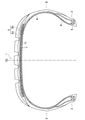
- FIG. 1 is a meridional sectional view showing a pneumatic radial tire according to an embodiment of the present invention.
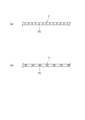
- FIG. 2 is an explanatory view schematically showing the arrangement of the belt layer (single wire).
- a pneumatic tire of the present invention includes a tread portion 1, a pair of sidewall portions 2 arranged on both sides of the tread portion 1, and a sidewall portion 2 which is arranged inside a tire radial direction. And a pair of bead portions 3.
- reference numeral CL indicates the tire equator.
- FIG. 1 is not drawn because it is a meridional cross-sectional view, the tread portion 1, the sidewall portion 2, and the bead portion 3 each extend in the tire circumferential direction to form an annular shape.
- the basic structure of the shape is constructed.
- each tire constituent member extends in the tire circumferential direction to form an annular shape.
- a plurality of (four in the illustrated example) main grooves extending in the tire circumferential direction are formed on the outer surface of the tread portion 1, but the number of main grooves is not particularly limited.
- various grooves and sipe including a lug groove extending in the tire width direction can be formed.
- a carcass layer 4 including a plurality of reinforcing cords (carcass cords) extending in the tire radial direction is mounted between the pair of left and right bead portions 3.
- a bead core 5 is embedded in each bead portion, and a bead filler 6 having a substantially triangular cross section is arranged on the outer periphery of the bead core 5.
- the carcass layer 4 is folded around the bead core 5 from the inner side to the outer side in the tire width direction.
- the bead core 5 and the bead filler 6 are provided around the carcass layer 4 in the main body portion (the portion from the tread portion 1 to each sidewall portion 2 to each bead portion 3) and the folded portion (each bead portion 3 around the bead core 5). (The portion that is folded back and extends toward the side wall portion 2 side).
- each belt layer 7 includes a plurality of reinforcing cords (belt cords) inclined with respect to the tire circumferential direction, and the belt cords are arranged so as to intersect each other between the layers.
- the inclination angle of the belt cord with respect to the tire circumferential direction is set in the range of, for example, 10° to 40°.
- a steel cord is used as the belt cord.
- a belt reinforcing layer 8 is provided on the outer peripheral side of the belt layer 7 for the purpose of improving high-speed durability and reducing road noise.
- the belt reinforcing layer 8 includes a reinforcing cord (belt reinforcing cord) oriented in the tire circumferential direction.
- the angle of the belt reinforcing cord with respect to the tire circumferential direction is set to, for example, 0° to 5°.
- the belt reinforcing layer 8 must include a full cover layer 8a that covers the entire area of the belt layer 7 and optionally a pair of edge cover layers 8b that locally cover both ends of the belt layer 7. (In the illustrated example, both the full cover layer 8a and the edge cover layer 8b are included).
- the belt-reinforcing layer 8 may be formed by spirally winding a strip material in which at least one belt-reinforcing cord is aligned and covered with a coat rubber, in a tire circumferential direction, and particularly preferably a jointless structure.
- the present invention relates to the belt cords forming the belt layer 7 and the belt reinforcing layer 8 described above, the basic structure of the entire tire is not limited to the above.
- the belt cord forming the belt layer 7 is not a twisted cord formed by twisting a plurality of strands, but a single wire.
- the wire diameter of this single wire is 0.30 mm or more, preferably 0.33 mm or more.
- the wire diameter of the single wire is 0.45 mm or less, preferably 0.40 mm or less.
- one single wire may be arranged at intervals as shown in FIG. 2A, and a plurality of single wires may be arranged as shown in FIG. (In the figure, two single wires) may be aligned, and a plurality of aligned single wires may be arranged at intervals.
- the specific structure of the single wire is not particularly limited as long as it satisfies the above wire diameter.
- a single wire with twist around the wire axis twisted single wire
- a single wire with a flat cross section flat single wire
- a single wire with a spiral shape spiral single wire
- a single wire with a plane wave shape Various types of single wire that can be used for a pneumatic tire, such as a wire (two-dimensional corrugated single wire), can be adopted.
- this wire amount is preferable Is preferably in the range of 50 to 280. This improves the structure of the belt layer 7, which is advantageous for improving steering stability while maintaining durability. If the wire amount is less than 50, the proportion of the single wire occupying the belt layer 7 decreases, which may reduce the steering stability. If the wire amount exceeds 280, belt separation may occur.
- the belt reinforcing cord constituting the belt reinforcing layer 8 is a polyester having an elongation of 2.0% to 4.0% when loaded with 2.0 cN/dtex, and preferably 2.6% to 3.4%.
- Fiber cord is used.
- the polyester fiber include polyethylene terephthalate fiber (PET fiber).
- PET fiber polyethylene terephthalate fiber
- the elongation at 2.0 cN/dtex load conforms to JIS-L1017 "Chemical fiber tire cord test method", and is determined by a tensile test under the conditions of a gripping interval of 250 mm and a pulling speed of 300 ⁇ 20 mm/min. And the elongation rate (%) of the sample cord measured under a load of 2.0 cN/dtex.
- the pneumatic tire of the present invention has durability. While maintaining, it is possible to improve steering stability during normal driving and circuit driving. That is, by using polyethylene terephthalate fiber (PET fiber) having the above-mentioned physical properties and high rigidity in the belt reinforcing layer 8, it is possible to improve steering stability during normal running. Further, since the belt reinforcing layer 8 can effectively suppress the rising of the belt end portion at the time of high speed running, the high speed durability can be improved.
- PET fiber polyethylene terephthalate fiber
- the belt layer by using the above-mentioned single wire, it is possible to suppress the elongation of the belt cord and to make the belt layer 7 thin. Can also suppress heat generation. Therefore, it is possible to prevent a decrease in the elastic modulus (rigidity) of the belt reinforcing layer 8 (PET fiber cord), and it is possible to ensure good steering stability during ultra-high speed traveling.
- the belt cord may be stretched due to the twisted structure, and the belt layer 7 cannot be thinned. Therefore, the above effect cannot be obtained.
- the wire diameter of the single wire is less than 0.30 mm, the single wire is too thin to ensure sufficient durability of the wire itself. If the wire diameter of the single wire exceeds 0.45 mm, the belt layer 7 cannot be made sufficiently thin as compared with the case where a conventional twisted cord is used. If the elongation of the organic fiber cords constituting the belt reinforcing layer 8 under a load of 2.0 cN/dtex is less than 2.0%, the rigidity is too high, and the durability against separation decreases.
- the belt reinforcing cord (PET fiber cord) having the above-mentioned physical properties
- it is advisable to optimize the dipping process for example.
- the belt reinforcing cord (PET fiber cord) is subjected to an adhesive dipping treatment, but in the normalizing step after the two bath treatment, the ambient temperature is within the range of 210°C to 250°C. It is preferable to set the cord tension in the range of 2.2 ⁇ 10 -2 N/tex to 6.7 ⁇ 10 -2 N/tex.
- the belt reinforcing cord (PET fiber cord) can be provided with the desired physical properties as described above.
- the cord tension in the normalizing process is smaller than 2.2 ⁇ 10 -2 N/tex, the cord elastic modulus will be low and the steering stability will be reduced, while conversely it will be larger than 6.7 ⁇ 10 -2 N/tex. And the cord elastic modulus becomes high, and separation easily occurs.
- tire size of 235/40R18 has the basic structure illustrated in FIG. 1, and is used for the structure of the steel cord that forms the belt layer, the wire diameter (cord diameter), and the organic fiber cord that forms the belt reinforcing layer.
- Tires of Conventional Example 1, Comparative Examples 1 to 3 and Examples 1 to 5 in which the type of the organic fiber and the elongation of the organic fiber cord when loaded with 2.0 cN/dtex were varied as shown in Table 1 were manufactured.
- the belt reinforcing layer is a joint in which a strip formed by aligning one organic fiber cord (nylon 66 fiber cord or PET fiber cord) and coating it with coat rubber is spirally wound in the tire circumferential direction. It has a less structure.
- the cord driving density in the strip is 50/50 mm.
- the organic fiber cord (nylon 66 fiber cord or PET fiber cord) has a structure of 1400 dtex/2 for Conventional Example 1 and Comparative Example 2, and has a structure of 1100 dtex/2 for the other examples.
- N66 is indicated for nylon 66 fiber cord and “PET” for PET fiber cord.
- test tire Durability Each test tire was assembled on a wheel with a rim size of 18 ⁇ 8J, oxygen was sealed at an internal pressure of 230 kPa, and the oxygen was released from the inside after maintaining it in a chamber kept at room temperature of 60° C. for 2 weeks. Filled with air.
- the test tire subjected to this pretreatment had an ambient temperature of 38 ⁇ 3° C., a running speed of 50 km/hr, a slip angle of 0 ⁇ 3°, and a maximum load. Under a fluctuation condition of 70 ⁇ 40%, the load and slip angle were changed by a rectangular wave of 0.083 Hz, and the vehicle was run for 5000 hours for 100 hours.
- the tires of Examples 1 to 5 were, in comparison with the reference example of Conventional Example 1, maintained tire durability while maintaining steering stability during normal driving and steering stability during circuit driving. Has been improved, and these performances have been highly compatible.
- Comparative Example 1 since the twisted cord was used as the belt cord, the steering stability during running on the circuit was lowered.
- Comparative Example 2 since the organic fiber cord constituting the belt reinforcing layer is made of nylon 66 and has a large intermediate elongation under a load of 2.0 cN/dtex, the steering stability during normal driving and the steering stability during circuit driving are large. It was not possible to obtain the effect of improving. In Comparative Example 3, since the wire diameter of the single wire was too small, the tire durability was lowered.
- tread part 2 sidewall part 3 bead part 4 carcass layer 5 bead core 6 bead filler 7 belt layer 7C belt cord 8 belt reinforcing layer CL tire equator
Landscapes
- Engineering & Computer Science (AREA)
- Mechanical Engineering (AREA)
- Tires In General (AREA)
Abstract
有機繊維コードからなるベルト補強層を備えた空気入りタイヤであって、耐久性を維持しながら、通常走行時およびサーキット走行時の操縦安定性を向上することを可能にした空気入りタイヤを提供する。トレッド部1においてカーカス層4の外周側に配置されるベルト層7を、素線径が0.30mm以上0.45mm以下である単線ワイヤで構成し、ベルト層7の外周側に配置されるベルト補強層を、ポリエチレンテレフタレート繊維で構成されて2.0cN/dtex負荷時の中間伸度が2.0%~4.0%である有機繊維コードで構成する。
Description
本発明は、有機繊維コードからなるベルト補強層を備えた空気入りタイヤに関し、更に詳しくは、耐久性を維持しながら、通常走行時およびサーキット走行時の操縦安定性を向上することを可能にした空気入りタイヤに関する。
空気入りタイヤにおいては、一対のビード部間にカーカス層が装架され、トレッド部におけるカーカス層の外周側に複数層のベルト層が配置され、更に、ベルト層の外周側にタイヤ周方向に沿って螺旋状に巻回された複数本の有機繊維コードを含むベルト補強層が配置されている。このようなベルト補強層は、高速走行時のベルト端部のせり上がりを抑制するので、高速耐久性の改善に寄与する。
このようなベルト補強層に使用される有機繊維コードとしてはナイロン繊維コードが主流であるが、ナイロン繊維コードに比べて高弾性であり、かつ安価なポリエチレンテレフタレート繊維コード(以下、PET繊維コードと言う)を使用することが提案されている(例えば、特許文献1参照)。しかしながら、PET繊維コードの弾性率(剛性)には温度依存性があり、サーキット走行のような超高速走行時には、弾性率(剛性)が低下して操縦安定性が低下する虞がある。そのため、PET繊維コードからなるベルト補強層を備えた空気入りタイヤにおいて、耐久性、通常走行時およびサーキット走行時の操縦安定性を向上する対策が求められている。
本発明の目的は、有機繊維コードからなるカーカス層を備えた空気入りタイヤであって、耐久性を維持しながら、通常走行時およびサーキット走行時の操縦安定性を向上することを可能にした空気入りタイヤを提供することにある。
上記目的を達成するための本発明の空気入りタイヤは、タイヤ周方向に延在して環状をなすトレッド部と、該トレッド部の両側に配置された一対のサイドウォール部と、これらサイドウォール部のタイヤ径方向内側に配置された一対のビード部とを備え、前記一対のビード部間に装架された少なくとも1層のカーカス層と、前記トレッド部における前記カーカス層の外周側に配置された複数層のベルト層と、前記ベルト層の外周側に配置されたベルト補強層とを有する空気入りタイヤにおいて、前記ベルト層を構成するベルトコードが、素線径が0.30mm以上0.45mm以下である単線ワイヤであり、前記ベルト補強層を構成するベルト補強コードが、ポリエチレンテレフタレート繊維からなる有機繊維コードであり、前記ベルト補強コードの2.0cN/dtex負荷時の中間伸度が2.0%~4.0%であることを特徴とする。
本発明では、上述のように、ベルト補強層に2.0cN/dtex負荷時の伸びが2.0%~4.0%であり、剛性の高いポリエチレンテレフタレート繊維(PET繊維)からなる有機繊維コードを用いているので、通常走行時の操縦安定性を向上することができる。また、このベルト補強層により高速走行時のベルト端部のせり上がりが効果的に抑制できるので、高速耐久性を向上することもできる。一方で、ベルト層に単線ワイヤを用いているので、ベルトコードの伸びが抑制でき、また、ベルト層を薄くすることができるため、サーキット走行のような超高速走行時であっても発熱を抑制することができる。そのため、ベルト補強層(PET繊維コード)の弾性率(剛性)の低下を防止することができ、超高速走行時の操縦安定性を良好に確保することができる。
本発明では、単線ワイヤの素線径が0.33mm以上0.40mm以下であることが好ましい。これにより、単線ワイヤ自体の耐久性を確保することができ、耐久性を維持しながら、通常走行時およびサーキット走行時の操縦安定性を向上するには有利になる。
以下、本発明の構成について添付の図面を参照しながら詳細に説明する。
図1に示すように、本発明の空気入りタイヤは、トレッド部1と、このトレッド部1の両側に配置された一対のサイドウォール部2と、サイドウォール部2のタイヤ径方向内側に配置された一対のビード部3とを備えている。図1において、符号CLはタイヤ赤道を示す。図1は子午線断面図であるため描写されないが、トレッド部1、サイドウォール部2、ビード部3は、それぞれタイヤ周方向に延在して環状を成しており、これにより空気入りタイヤのトロイダル状の基本構造が構成される。以下、図1を用いた説明は基本的に図示の子午線断面形状に基づくが、各タイヤ構成部材はいずれもタイヤ周方向に延在して環状を成すものである。
図示の例では、トレッド部1の外表面にタイヤ周方向に延びる複数本(図示の例では4本)の主溝が形成されているが、主溝の本数は特に限定されない。また、主溝の他にタイヤ幅方向に延びるラグ溝を含む各種の溝やサイプを形成することもできる。
左右一対のビード部3間にはタイヤ径方向に延びる複数本の補強コード(カーカスコード)を含むカーカス層4が装架されている。各ビード部には、ビードコア5が埋設されており、そのビードコア5の外周上に断面略三角形状のビードフィラー6が配置されている。カーカス層4は、ビードコア5の廻りにタイヤ幅方向内側から外側に折り返されている。これにより、ビードコア5およびビードフィラー6はカーカス層4の本体部(トレッド部1から各サイドウォール部2を経て各ビード部3に至る部分)と折り返し部(各ビード部3においてビードコア5の廻りに折り返されて各サイドウォール部2側に向かって延在する部分)とにより包み込まれている。
一方、トレッド部1におけるカーカス層4の外周側には複数層(図示の例では2層)のベルト層7が埋設されている。各ベルト層7は、タイヤ周方向に対して傾斜する複数本の補強コード(ベルトコード)を含み、かつ層間でベルトコードが互いに交差するように配置されている。これらベルト層7において、ベルトコードのタイヤ周方向に対する傾斜角度は例えば10°~40°の範囲に設定されている。ベルトコードとしては例えばスチールコードが使用される。
ベルト層7の外周側には、高速耐久性の向上とロードノイズの低減を目的として、ベルト補強層8が設けられている。ベルト補強層8は、タイヤ周方向に配向する補強コード(ベルト補強コード)を含む。ベルト補強層8において、ベルト補強コードはタイヤ周方向に対する角度が例えば0°~5°に設定されている。本発明では、ベルト補強層8は、ベルト層7の全域を覆うフルカバー層8aを必ず含み、任意でベルト層7の両端部を局所的に覆う一対のエッジカバー層8bを含む構成にすることができる(図示の例では、フルカバー層8aおよびエッジカバー層8bの両方を含む)。ベルト補強層8は、少なくとも1本のベルト補強コードを引き揃えてコートゴムで被覆したストリップ材をタイヤ周方向に螺旋状に巻回して構成するとよく、特にジョイントレス構造とすることが望ましい。
本発明は、上述のベルト層7を構成するベルトコードとベルト補強層8を構成するベルトコードに関するものであるので、タイヤ全体の基本構造は上述のものに限定されない。
本発明において、ベルト層7を構成するベルトコードは、複数本の素線を撚り合わせた撚りコードではなく、単線ワイヤで構成される。この単線ワイヤの素線径は0.30mm以上、好ましくは0.33mm以上である。このように、ベルト層7に単線ワイヤを用いることで、ベルトコードの伸びが抑制でき、また、ベルト層7を薄くすることができるため、サーキット走行のような超高速走行時であっても発熱を抑制することができる。尚、ベルト層7を薄くする観点からは、単線ワイヤの素線径は0.45mm以下、好ましくは0.40mm以下であるとよい。
単線ワイヤでベルト層7を構成するにあたって、図2(a)に示すように、単線ワイヤを1本ずつ間隔をおいて配列してもよく、図2(b)に示すように、複数本(図では2本)の単線ワイヤを引き揃えて、引き揃えた複数本ごとに間隔をおいて配列してもよい。このとき、単線ワイヤ同士の間隔(引き揃えた複数本ごとの間隔)は、例えば0.30mm~1.80mmに設定することが好ましい。
単線ワイヤは、上述の素線径を満たしていれば、具体的な構造は特に限定されない。例えば、ワイヤ軸廻りに捩じりを加えた単線ワイヤ(捩じり単線)、断面偏平形状の単線ワイヤ(偏平単線)、螺旋状に型付けした単線ワイヤ(スパイラル単線)、平面波形状に型付けした単線ワイヤ(2次元波付け単線)など、空気入りタイヤに用いることができる各種単線ワイヤを採用することができる。
単線ワイヤの単位質量(g/m)と単線ワイヤの長手方向と直交する向きの幅50mm当たりの単線ワイヤの打ち込み本数(本/50mm)との積をワイヤ量と定義すると、このワイヤ量は好ましくは50~280の範囲内であるとよい。これにより、ベルト層7の構造が良好になるので、耐久性を維持しながら操縦安定性を向上するには有利になる。ワイヤ量が50未満であると、ベルト層7に占める単線ワイヤの割合が減少するため、操縦安定性が低下する虞がある。ワイヤ量が280を超えると、ベルトセパレーションを発生させる虞がある。
本発明では、ベルト補強層8を構成するベルト補強コードとして、2.0cN/dtex負荷時の伸びが2.0%~4.0%、好ましくは2.6%~3.4%であるポリエステル繊維コードが使用される。ポリエステル繊維としては、ポリエチレンテレフタレート繊維(PET繊維)を例示することができる。尚、本発明において、2.0cN/dtex負荷時の伸びは、JIS‐L1017の「化学繊維タイヤコード試験方法」に準拠し、つかみ間隔250mm、引張速度300±20mm/分の条件にて引張試験を実施し、2.0cN/dtex負荷時に測定される試料コードの伸び率(%)である。
このように、特定の素線径の単線ワイヤからなるベルト層7と特定の物性を有する有機繊維コードからなるベルト補強層8を組み合わせて用いることで、本発明の空気入りタイヤは、耐久性を維持しながら、通常走行時およびサーキット走行時の操縦安定性を向上することができる。即ち、ベルト補強層8において、上述の物性を有して剛性の高いポリエチレンテレフタレート繊維(PET繊維)を用いることで、通常走行時の操縦安定性を向上することができる。また、このベルト補強層8により高速走行時のベルト端部のせり上がりが効果的に抑制できるので、高速耐久性を向上することもできる。一方で、ベルト層においては、上述の単線ワイヤを用いることで、ベルトコードの伸びを抑制し、また、ベルト層7を薄くすることができるため、サーキット走行のような超高速走行時であっても発熱を抑制することができる。そのため、ベルト補強層8(PET繊維コード)の弾性率(剛性)の低下を防止することができ、超高速走行時の操縦安定性を良好に確保することができる。
このとき、ベルト層7を構成するベルトコードとして単線ワイヤではなく撚りコードが用いられると、ベルトコードに撚り構造に起因する伸びが生じる可能性があり、また、ベルト層7の薄肉化が達成できないため、上述の効果を得ることができない。単線ワイヤの素線径が0.30mm未満であると、単線ワイヤが細すぎてワイヤ自体の耐久性が十分に確保できない。単線ワイヤの素線径が0.45mmを超えると、従来の撚りコードを用いた場合に比べて、ベルト層7を充分に薄くすることができない。ベルト補強層8を構成する有機繊維コードの2.0cN/dtex負荷時の伸びが2.0%未満であると、剛性が高すぎるため、セパレーションに対する耐久性が低下する。ベルト補強層8を構成する有機繊維コードの2.0cN/dtex負荷時の伸びが4.0%を超えると、ベルト補強層8の剛性が低くなり、良好な操縦安定性を得ることが難しくなる。
上述のような物性を有するベルト補強コード(PET繊維コード)を得るために、例えばディップ処理を適正化すると良い。つまり、カレンダー工程に先駆けて、ベルト補強コード(PET繊維コード)には接着剤のディップ処理が行われるが、2浴処理後のノルマライズ工程において、雰囲気温度を210℃~250℃の範囲内に設定し、コード張力を2.2×10⁻²N/tex~6.7×10-2N/texの範囲に設定することが好ましい。これにより、ベルト補強コード(PET繊維コード)に上述のような所望の物性を付与することができる。ノルマライズ工程におけるコード張力が2.2×10-2N/texよりも小さいとコード弾性率が低くなり、操縦安定性が低下し、逆に6.7×10-2N/texよりも大きいとコード弾性率が高くなり、セパレーションが発生しやすくなる。
タイヤサイズが235/40R18であり、図1に例示する基本構造を有し、ベルト層を構成するスチールコードの構造、素線径(コード径)、ベルト補強層を構成する有機繊維コードに用いられた有機繊維の種類、有機繊維コードの2.0cN/dtex負荷時の伸びを、表1のように異ならせた従来例1、比較例1~3、実施例1~5のタイヤを製作した。
いずれの例においても、ベルト補強層は、1本の有機繊維コード(ナイロン66繊維コードまたはPET繊維コード)を引き揃えてコートゴムで被覆してなるストリップをタイヤ周方向に螺旋状に巻回したジョイントレス構造を有している。ストリップにおけるコード打ち込み密度は50本/50mmである。また、有機繊維コード(ナイロン66繊維コードまたはPET繊維コード)は、従来例1および比較例2については1400dtex/2の構造を有し、他の例は1100dtex/2の構造を有する。
表1の「有機繊維の種類」の欄については、ナイロン66繊維コードの場合を「N66」、PET繊維コードの場合を「PET」と表示した。
これら試験タイヤについて、下記の評価方法により、通常走行時の操縦安定性、サーキット走行時の操縦安定性、タイヤ耐久性を評価し、その結果を表1に併せて示した。
操縦安定性(通常走行時、サーキット走行時)
各試験タイヤをリムサイズ18×8Jのホイールに組み付けて、試験車両(排気量3000cc)に装着し、空気圧を230kPaに設定し、速度30km/h~100km/h(通常走行時)、速度100km/h~270km/h(サーキット走行時)の2通りの条件で、操縦安定性について舗装路からなるテストコースにて5名のテストドライバーによる官能評価を行った。評価結果はそれぞれ従来例1の結果を3点(基準)とする5点法で採点し、5名のテストドライバーの点数の平均値を示した。この点数が大きいほど高速走行時の操縦安定性が優れていることを意味する。
各試験タイヤをリムサイズ18×8Jのホイールに組み付けて、試験車両(排気量3000cc)に装着し、空気圧を230kPaに設定し、速度30km/h~100km/h(通常走行時)、速度100km/h~270km/h(サーキット走行時)の2通りの条件で、操縦安定性について舗装路からなるテストコースにて5名のテストドライバーによる官能評価を行った。評価結果はそれぞれ従来例1の結果を3点(基準)とする5点法で採点し、5名のテストドライバーの点数の平均値を示した。この点数が大きいほど高速走行時の操縦安定性が優れていることを意味する。
タイヤ耐久性
各試験タイヤをリムサイズ18×8Jのホイールに組み付けて、内圧230kPaで酸素を封入し、室温60℃に保持されたチャンバー内に2週間保持した後、内部の酸素を解放し、内圧160kPaで空気を充填した。この前処理を施した試験タイヤを、ドラム表面が平滑な鋼製で直径1707mmのドラム試験機を用いて、周辺温度38±3℃、走行速度50km/hr、スリップ角0±3°、最大荷重の70±40%の変動条件下で、荷重とスリップ角を0.083Hzの矩形波で変動させて、100時間、5000km走行させた。走行後にタイヤを切開し、ベルト幅方向端部における幅方向へのセパレーション長さを測定した。評価結果は、従来例1の測定値の逆数を100とする指数で示した。この指数値が大きいほどセパレーション長さが小さく、ベルトエッジセパレーションに対する耐久性に優れることを意味する。指数値が「98」以上であれば従来レベルの良好な耐久性を維持したことを意味する。
各試験タイヤをリムサイズ18×8Jのホイールに組み付けて、内圧230kPaで酸素を封入し、室温60℃に保持されたチャンバー内に2週間保持した後、内部の酸素を解放し、内圧160kPaで空気を充填した。この前処理を施した試験タイヤを、ドラム表面が平滑な鋼製で直径1707mmのドラム試験機を用いて、周辺温度38±3℃、走行速度50km/hr、スリップ角0±3°、最大荷重の70±40%の変動条件下で、荷重とスリップ角を0.083Hzの矩形波で変動させて、100時間、5000km走行させた。走行後にタイヤを切開し、ベルト幅方向端部における幅方向へのセパレーション長さを測定した。評価結果は、従来例1の測定値の逆数を100とする指数で示した。この指数値が大きいほどセパレーション長さが小さく、ベルトエッジセパレーションに対する耐久性に優れることを意味する。指数値が「98」以上であれば従来レベルの良好な耐久性を維持したことを意味する。

表1から判るように、実施例1~5のタイヤは、基準となる従来例1との対比において、タイヤ耐久性を維持しながら、通常走行時の操縦安定性とサーキット走行時の操縦安定性を向上し、これら性能を高度に両立した。一方、比較例1は、ベルトコードとして撚りコードが用いられているため、サーキット走行時の操縦安定性が低下した。比較例2は、ベルト補強層を構成する有機繊維コードがナイロン66からなり、2.0cN/dtex負荷時の中間伸度が大きいため、通常走行時の操縦安定性とサーキット走行時の操縦安定性を向上する効果が得られなかった。比較例3は、単線ワイヤの素線径が小さすぎるため、タイヤ耐久性が低下した。
1 トレッド部
2 サイドウォール部
3 ビード部
4 カーカス層
5 ビードコア
6 ビードフィラー
7 ベルト層
7C ベルトコード
8 ベルト補強層
CL タイヤ赤道
2 サイドウォール部
3 ビード部
4 カーカス層
5 ビードコア
6 ビードフィラー
7 ベルト層
7C ベルトコード
8 ベルト補強層
CL タイヤ赤道
Claims (2)
- タイヤ周方向に延在して環状をなすトレッド部と、該トレッド部の両側に配置された一対のサイドウォール部と、これらサイドウォール部のタイヤ径方向内側に配置された一対のビード部とを備え、前記一対のビード部間に装架された少なくとも1層のカーカス層と、前記トレッド部における前記カーカス層の外周側に配置された複数層のベルト層と、前記ベルト層の外周側に配置されたベルト補強層とを有する空気入りタイヤにおいて、
前記ベルト層を構成するベルトコードが、素線径が0.30mm以上0.45mm以下である単線ワイヤであり、
前記ベルト補強層を構成するベルト補強コードが、ポリエチレンテレフタレート繊維からなる有機繊維コードであり、前記ベルト補強コードの2.0cN/dtex負荷時の中間伸度が2.0%~4.0%であることを特徴とする空気入りタイヤ。 - 前記単線ワイヤの素線径が0.33mm以上0.40mm以下であることを特徴とする請求項1に記載の空気入りタイヤ。
Priority Applications (3)
| Application Number | Priority Date | Filing Date | Title |
|---|---|---|---|
| DE112019006708.7T DE112019006708B4 (de) | 2019-02-22 | 2019-12-12 | Luftreifen |
| US17/310,682 US20220041017A1 (en) | 2019-02-22 | 2019-12-12 | Pneumatic tire |
| CN201980091963.8A CN113453913A (zh) | 2019-02-22 | 2019-12-12 | 充气轮胎 |
Applications Claiming Priority (2)
| Application Number | Priority Date | Filing Date | Title |
|---|---|---|---|
| JP2019-030872 | 2019-02-22 | ||
| JP2019030872A JP6680373B1 (ja) | 2019-02-22 | 2019-02-22 | 空気入りタイヤ |
Publications (1)
| Publication Number | Publication Date |
|---|---|
| WO2020170573A1 true WO2020170573A1 (ja) | 2020-08-27 |
Family
ID=70166464
Family Applications (1)
| Application Number | Title | Priority Date | Filing Date |
|---|---|---|---|
| PCT/JP2019/048775 Ceased WO2020170573A1 (ja) | 2019-02-22 | 2019-12-12 | 空気入りタイヤ |
Country Status (5)
| Country | Link |
|---|---|
| US (1) | US20220041017A1 (ja) |
| JP (1) | JP6680373B1 (ja) |
| CN (1) | CN113453913A (ja) |
| DE (1) | DE112019006708B4 (ja) |
| WO (1) | WO2020170573A1 (ja) |
Cited By (1)
| Publication number | Priority date | Publication date | Assignee | Title |
|---|---|---|---|---|
| WO2023026952A1 (ja) * | 2021-08-24 | 2023-03-02 | 横浜ゴム株式会社 | 空気入りタイヤ |
Families Citing this family (5)
| Publication number | Priority date | Publication date | Assignee | Title |
|---|---|---|---|---|
| JP7806409B2 (ja) * | 2021-07-27 | 2026-01-27 | 住友ゴム工業株式会社 | タイヤ |
| JP7773029B2 (ja) * | 2021-09-07 | 2025-11-19 | 横浜ゴム株式会社 | 空気入りタイヤ |
| JP7744299B2 (ja) * | 2022-05-26 | 2025-09-25 | 株式会社ブリヂストン | タイヤ |
| EP4335661B1 (en) * | 2022-09-09 | 2025-09-03 | Sumitomo Rubber Industries, Ltd. | Tire |
| EP4385760B1 (en) | 2022-12-16 | 2025-10-15 | Sumitomo Rubber Industries, Ltd. | Tire |
Citations (5)
| Publication number | Priority date | Publication date | Assignee | Title |
|---|---|---|---|---|
| JP2001322404A (ja) * | 2000-05-12 | 2001-11-20 | Bridgestone Corp | 空気入りラジアルタイヤ |
| JP2002046415A (ja) * | 2000-08-03 | 2002-02-12 | Bridgestone Corp | 空気入りラジアルタイヤ |
| WO2013099248A1 (ja) * | 2011-12-26 | 2013-07-04 | 横浜ゴム株式会社 | 空気入りラジアルタイヤ |
| JP2016203687A (ja) * | 2015-04-16 | 2016-12-08 | 株式会社ブリヂストン | 空気入りタイヤ |
| JP2016203686A (ja) * | 2015-04-16 | 2016-12-08 | 株式会社ブリヂストン | 空気入りタイヤ |
Family Cites Families (8)
| Publication number | Priority date | Publication date | Assignee | Title |
|---|---|---|---|---|
| JPH10203109A (ja) * | 1997-01-20 | 1998-08-04 | Yokohama Rubber Co Ltd:The | 空気入りラジアルタイヤ |
| JPH11217005A (ja) * | 1997-11-26 | 1999-08-10 | Bridgestone Corp | 空気入りラジアルタイヤ |
| JP4818495B2 (ja) * | 1999-08-25 | 2011-11-16 | 株式会社ブリヂストン | ラジアルタイヤ |
| JP2001354007A (ja) * | 2000-06-09 | 2001-12-25 | Sumitomo Rubber Ind Ltd | 空気入りラジアルタイヤ |
| JP2004058727A (ja) * | 2002-07-25 | 2004-02-26 | Yokohama Rubber Co Ltd:The | 乗用車用空気入りラジアルタイヤ |
| JP2005096121A (ja) * | 2003-09-22 | 2005-04-14 | Yokohama Rubber Co Ltd:The | 空気入りタイヤの製造方法及び空気入りタイヤ |
| JP5280426B2 (ja) * | 2010-11-16 | 2013-09-04 | 東洋ゴム工業株式会社 | 空気入りタイヤ |
| JP6004045B1 (ja) * | 2015-05-27 | 2016-10-05 | 横浜ゴム株式会社 | 空気入りタイヤ |
-
2019
- 2019-02-22 JP JP2019030872A patent/JP6680373B1/ja active Active
- 2019-12-12 CN CN201980091963.8A patent/CN113453913A/zh not_active Withdrawn
- 2019-12-12 US US17/310,682 patent/US20220041017A1/en not_active Abandoned
- 2019-12-12 WO PCT/JP2019/048775 patent/WO2020170573A1/ja not_active Ceased
- 2019-12-12 DE DE112019006708.7T patent/DE112019006708B4/de active Active
Patent Citations (5)
| Publication number | Priority date | Publication date | Assignee | Title |
|---|---|---|---|---|
| JP2001322404A (ja) * | 2000-05-12 | 2001-11-20 | Bridgestone Corp | 空気入りラジアルタイヤ |
| JP2002046415A (ja) * | 2000-08-03 | 2002-02-12 | Bridgestone Corp | 空気入りラジアルタイヤ |
| WO2013099248A1 (ja) * | 2011-12-26 | 2013-07-04 | 横浜ゴム株式会社 | 空気入りラジアルタイヤ |
| JP2016203687A (ja) * | 2015-04-16 | 2016-12-08 | 株式会社ブリヂストン | 空気入りタイヤ |
| JP2016203686A (ja) * | 2015-04-16 | 2016-12-08 | 株式会社ブリヂストン | 空気入りタイヤ |
Cited By (1)
| Publication number | Priority date | Publication date | Assignee | Title |
|---|---|---|---|---|
| WO2023026952A1 (ja) * | 2021-08-24 | 2023-03-02 | 横浜ゴム株式会社 | 空気入りタイヤ |
Also Published As
| Publication number | Publication date |
|---|---|
| CN113453913A (zh) | 2021-09-28 |
| JP6680373B1 (ja) | 2020-04-15 |
| DE112019006708B4 (de) | 2024-05-08 |
| DE112019006708T5 (de) | 2021-09-30 |
| JP2020132056A (ja) | 2020-08-31 |
| US20220041017A1 (en) | 2022-02-10 |
Similar Documents
| Publication | Publication Date | Title |
|---|---|---|
| JP6680373B1 (ja) | 空気入りタイヤ | |
| JP4053727B2 (ja) | 空気入りラジアルタイヤ | |
| JP6737349B2 (ja) | 空気入りラジアルタイヤ | |
| JP6809548B2 (ja) | 空気入りラジアルタイヤ | |
| JP7290200B2 (ja) | 空気入りタイヤ | |
| JP7010356B1 (ja) | 空気入りタイヤ | |
| CN113330149B (zh) | 充气子午线轮胎 | |
| JP2009173150A (ja) | ラジアルタイヤ | |
| JP7107255B2 (ja) | 空気入りタイヤ | |
| JP6988865B2 (ja) | 空気入りタイヤ | |
| JP7773029B2 (ja) | 空気入りタイヤ | |
| JP4097448B2 (ja) | 空気入りラジアルタイヤ | |
| EP4393722A1 (en) | Pneumatic tire | |
| JP5013522B2 (ja) | 空気入りラジアルタイヤ | |
| JP5767348B2 (ja) | 自動二輪車用空気入りタイヤ | |
| JP7572605B2 (ja) | 空気入りタイヤ | |
| JP2008290503A (ja) | 空気入りラジアルタイヤ | |
| JP2004058727A (ja) | 乗用車用空気入りラジアルタイヤ | |
| JP2024121060A (ja) | 空気入りタイヤ | |
| JP2021046054A (ja) | 空気入りラジアルタイヤ | |
| JP2010274817A (ja) | 自動二輪車用空気入りタイヤ |
Legal Events
| Date | Code | Title | Description |
|---|---|---|---|
| 121 | Ep: the epo has been informed by wipo that ep was designated in this application |
Ref document number: 19916224 Country of ref document: EP Kind code of ref document: A1 |
|
| 122 | Ep: pct application non-entry in european phase |
Ref document number: 19916224 Country of ref document: EP Kind code of ref document: A1 |