WO2020170314A1 - 鉛蓄電池 - Google Patents
鉛蓄電池 Download PDFInfo
- Publication number
- WO2020170314A1 WO2020170314A1 PCT/JP2019/005899 JP2019005899W WO2020170314A1 WO 2020170314 A1 WO2020170314 A1 WO 2020170314A1 JP 2019005899 W JP2019005899 W JP 2019005899W WO 2020170314 A1 WO2020170314 A1 WO 2020170314A1
- Authority
- WO
- WIPO (PCT)
- Prior art keywords
- electrode plate
- battery case
- convex portion
- separator
- rib
- Prior art date
- Legal status (The legal status is an assumption and is not a legal conclusion. Google has not performed a legal analysis and makes no representation as to the accuracy of the status listed.)
- Ceased
Links
Images







Classifications
-
- H—ELECTRICITY
- H01—ELECTRIC ELEMENTS
- H01M—PROCESSES OR MEANS, e.g. BATTERIES, FOR THE DIRECT CONVERSION OF CHEMICAL ENERGY INTO ELECTRICAL ENERGY
- H01M10/00—Secondary cells; Manufacture thereof
- H01M10/06—Lead-acid accumulators
-
- H—ELECTRICITY
- H01—ELECTRIC ELEMENTS
- H01M—PROCESSES OR MEANS, e.g. BATTERIES, FOR THE DIRECT CONVERSION OF CHEMICAL ENERGY INTO ELECTRICAL ENERGY
- H01M10/00—Secondary cells; Manufacture thereof
- H01M10/06—Lead-acid accumulators
- H01M10/12—Construction or manufacture
- H01M10/16—Suspending or supporting electrodes or groups of electrodes in the case
-
- H—ELECTRICITY
- H01—ELECTRIC ELEMENTS
- H01M—PROCESSES OR MEANS, e.g. BATTERIES, FOR THE DIRECT CONVERSION OF CHEMICAL ENERGY INTO ELECTRICAL ENERGY
- H01M50/00—Constructional details or processes of manufacture of the non-active parts of electrochemical cells other than fuel cells, e.g. hybrid cells
- H01M50/40—Separators; Membranes; Diaphragms; Spacing elements inside cells
- H01M50/463—Separators, membranes or diaphragms characterised by their shape
- H01M50/466—U-shaped, bag-shaped or folded
-
- Y—GENERAL TAGGING OF NEW TECHNOLOGICAL DEVELOPMENTS; GENERAL TAGGING OF CROSS-SECTIONAL TECHNOLOGIES SPANNING OVER SEVERAL SECTIONS OF THE IPC; TECHNICAL SUBJECTS COVERED BY FORMER USPC CROSS-REFERENCE ART COLLECTIONS [XRACs] AND DIGESTS
- Y02—TECHNOLOGIES OR APPLICATIONS FOR MITIGATION OR ADAPTATION AGAINST CLIMATE CHANGE
- Y02E—REDUCTION OF GREENHOUSE GAS [GHG] EMISSIONS, RELATED TO ENERGY GENERATION, TRANSMISSION OR DISTRIBUTION
- Y02E60/00—Enabling technologies; Technologies with a potential or indirect contribution to GHG emissions mitigation
- Y02E60/10—Energy storage using batteries
-
- Y—GENERAL TAGGING OF NEW TECHNOLOGICAL DEVELOPMENTS; GENERAL TAGGING OF CROSS-SECTIONAL TECHNOLOGIES SPANNING OVER SEVERAL SECTIONS OF THE IPC; TECHNICAL SUBJECTS COVERED BY FORMER USPC CROSS-REFERENCE ART COLLECTIONS [XRACs] AND DIGESTS
- Y02—TECHNOLOGIES OR APPLICATIONS FOR MITIGATION OR ADAPTATION AGAINST CLIMATE CHANGE
- Y02P—CLIMATE CHANGE MITIGATION TECHNOLOGIES IN THE PRODUCTION OR PROCESSING OF GOODS
- Y02P70/00—Climate change mitigation technologies in the production process for final industrial or consumer products
- Y02P70/50—Manufacturing or production processes characterised by the final manufactured product
Definitions
- the present invention relates to a lead storage battery.
- Lead-acid batteries are widely used for industrial and consumer use because of their reliability and low price, and there is particularly strong demand for lead-acid batteries for automobiles (so-called batteries).
- Patent Document 1 describes a lead-acid battery including a positive electrode plate and a negative electrode plate.
- the positive electrode plate and the negative electrode plate are alternately laminated with the separator interposed therebetween, and the current collectors of the positive electrode plate and the negative electrode plate are collectively welded to the strap for each polarity, and the cell-to-cell connecting portion or the electrode is attached to the strap.
- the poles are connected to each other to form an electrode plate group.
- the separator is arranged between the positive electrode plate and the negative electrode plate by accommodating the positive electrode plate or the negative electrode plate in the bag-shaped separator. And the electrode plate group configured in this way is housed in the battery case.
- an electrode group is inserted into the battery case through an opening formed on the upper surface of the battery case by an industrial machine such as a robot arm, so that the electrode plate group collides with the bottom of the battery case. There is something to do.
- the separator is sandwiched between the electrode and the bottom of the battery case, and therefore may be damaged due to collision between the electrode plate group and the bottom of the battery case.
- lead-acid batteries used in idling stop system vehicles are required to have higher performance, so the weight of the electrode plates tends to increase due to an increase in the number of electrode plates. Therefore, the separator is more likely to be damaged by the collision between the electrode plate group and the bottom of the battery case.
- one aspect of the present invention is to suppress the damage of the separator due to the collision between the electrode plate group and the bottom of the battery case.
- a lead-acid battery includes a positive electrode plate and a negative electrode plate, an electrode plate group in which a positive electrode plate and a negative electrode plate are stacked via a separator, and a battery case that houses the electrode plate group.
- the separators adjacent to each other via the target electrode plate which is one side are connected on the bottom side of the battery case of the target electrode plate, the separator has a base portion and a rib protruding from the base portion, and the rib is a base portion.
- a bottom rib portion disposed between the bottom portion and the bottom portion, and the battery case has a shape such that the base portion does not stick to the bottom when the electrode plate group is inserted into the battery case.
- the battery case has a shape in which the base of the separator does not stick to the bottom of the battery case when the electrode plate group is inserted into the battery case, so when the electrode plate group is inserted into the battery case, Even if the bottom and the bottom of the battery case collide with each other, the base of the separator can be prevented from being damaged by the collision. This can prevent the separator from being damaged due to the collision between the electrode plate group and the bottom of the battery case.
- the battery case may have a convex part that protrudes from the bottom part to the inside of the battery case and extends in a direction intersecting with the target electrode plate in a plan view, and the height of the convex part may be lower than the height of the bottom rib part.
- a convex portion is formed on the bottom of the battery case, but since the height of this convex portion is lower than the height of the bottom rib portion of the separator, the bottom rib portion is not placed on the convex portion and the bottom portion is not placed. Even when it falls down, it is possible to prevent the base portion from coming into contact with the convex portion. This can prevent the separator from being damaged due to the collision between the electrode plate group and the bottom of the battery case.
- the separator has a plurality of the bottom ribs
- the battery case has a protrusion protruding from the bottom to the inside of the battery case and extending in a direction intersecting the target electrode plate in a plan view, and the width of the protrusion. May be wider than the spacing between the bottom ribs.
- a convex portion is formed on the bottom of the battery case, but since the width of this convex portion is wider than the interval between the plurality of bottom rib portions of the separator, the bottom rib portion does not fall from the convex portion to the bottom. Can be suppressed to prevent the base portion from contacting the convex portion. This can prevent the separator from being damaged due to the collision between the electrode plate group and the bottom of the battery case.
- a plurality of convex portions may be formed at equal intervals.
- a plurality of convex portions are formed at equal intervals. Therefore, for example, when the height of the convex portion is lower than the height of the bottom rib portion, the bottom rib portion is easily placed on the convex portion. Further, for example, when the width of the convex portion is wider than the distance between the bottom rib portions, it is possible to prevent the bottom rib portion from falling from the convex portion.
- the convex portion may be formed into a rounded corner in a cross section orthogonal to the extending direction of the convex portion.
- the protrusions are formed into rounded corners, it is possible to prevent the separator from being damaged even if the base contacts the protrusions.
- the radius of the rounded corner of the convex portion (the radius of the rounded corner of the convex portion) may be 0.5 mm or more and 1.0 mm or less.
- the radius of the rounded corners of the protrusions is 0.5 mm or more and 1.0 mm or less, so that the separator is damaged when the base contacts the protrusions while suppressing the protrusions from becoming too large. Can be suppressed.
- the surface of the convex portion may be formed in a curved shape from the lower end to the upper end in a cross section orthogonal to the extending direction of the convex portion.
- the surface of the convex portion is formed in a curved shape from the lower end to the upper end, it is possible to prevent the separator from being damaged even if the base portion contacts the convex portion.
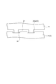
- the bottom part may have a concave part that is recessed from the outside of the battery case at a position corresponding to the convex part.
- the bottom of the battery case since the bottom of the battery case has the recessed portion that is recessed from the outside of the battery container at the position corresponding to the protrusion, it is possible to prevent the bottom of the battery container from locally thickening due to the protrusion. .. This can suppress an increase in the material of the battery case.
- the bottom may be of uniform thickness.
- the bottom of the battery case since the bottom of the battery case has a uniform thickness, even if a convex portion is formed on the bottom of the battery case, it is possible to suppress an increase in the material of the battery case.
- the bottom may have a groove that is recessed from the inside of the battery case at the end of the bottom.
- the bottom of the battery case has a groove recessed from the inside of the battery case at the end of the bottom, so the battery case is raised when the outer shape of the battery case is larger than the electrode plate group. be able to. Thereby, the electrode plate group can be appropriately accommodated in the battery case while suppressing an increase in the material of the battery case.
- the groove may be formed on the entire peripheral edge of the bottom.
- the groove since the groove is formed at the entire peripheral edge of the bottom of the battery case, for example, when the outer shape of the battery case is larger than the electrode plate group, it is possible to further suppress the increase in the material of the battery case. You can
- the area of the groove may be 6.0% or more and 10% or less of the area of the bottom.
- the area of the groove portion is 6.0% or more and 10% or less of the area of the bottom portion of the battery case in plan view, so that the bottom rib portion of the separator can be prevented from falling into the groove portion.
- the present invention it is possible to prevent the separator from being damaged due to the collision between the electrode plate group and the bottom of the battery case.
- FIG. 6 is a sectional view taken along line VI-VI shown in FIG. 5. It is a perspective view which shows a part of battery case shown in FIG. It is a top view which shows a part of battery case shown in FIG. FIG.
- FIGS. 7 and 8 are sectional views taken along line IX-IX shown in FIGS. 7 and 8. It is a figure which shows the relationship between a bag-shaped separator and the bottom part of a battery case. It is a figure which shows the relationship between a bag-shaped separator and the bottom part of a battery case. It is sectional drawing which shows the modification of the bottom part of a battery case. It is sectional drawing which shows some modification examples of the bottom part of a battery case. It is sectional drawing which shows the modification of the bottom part of a battery case. It is a top view which shows the modification of the bottom part of a battery case. It is a front view which shows the collector which has the rib of the modification of the separator.
- the up-down direction means the up-down direction in a lead storage battery.
- the numerical range indicated by using "to” indicates a range including the numerical values before and after "to” as the minimum value and the maximum value, respectively.
- “A or B” may include either one of A and B, or may include both.
- the lead storage battery 1 includes a battery case 2 having an open top surface and a lid 3 that closes the opening of the battery case 2.
- the battery case 2 and the lid 3 are made of polypropylene, for example.
- the lid 3 is provided with a positive electrode terminal 4, a negative electrode terminal 5, and a liquid port plug 6 that closes a liquid injection port provided in the lid 3.
- an electrode plate group 7 Inside the battery case 2, an electrode plate group 7, a positive electrode column (not shown) connecting the electrode plate group 7 to the positive electrode terminal 4, and a negative electrode column 8 connecting the electrode plate group 7 to the negative electrode terminal 5, It contains an electrolytic solution such as dilute sulfuric acid.
- the electrode plate group 7 is configured by laminating a plurality of positive electrode plates 9 and a plurality of negative electrode plates 10 with a separator 11 interposed therebetween.
- the positive electrode plate 9 has a positive electrode grid body (positive electrode current collector) 12 and a positive electrode active material (positive electrode material) 13.
- the positive electrode grid body 12 is a grid body of the positive electrode plate 9, and has a grid portion 12a and an ear portion 12b integrally formed with the grid portion 12a and protruding from one end of the grid portion 12a.
- the positive electrode active material 13 is an active material of the positive electrode plate 9 and is held by the positive electrode grid 12.
- the negative electrode plate 10 includes a negative electrode grid body (negative electrode current collector) 14 and a negative electrode active material (negative electrode material) 15.
- the negative electrode grid body 14 is a grid body of the negative electrode plate 10, and has a grid portion 14a and an ear portion 14b integrally formed with the grid portion 14a and protruding from one end of the grid portion 14a.
- the negative electrode active material 15 is an active material of the negative electrode plate 10, and is held by the negative electrode grid body 14.
- the positive electrode grid body 12 and the negative electrode grid body 14 are formed of a lead alloy.
- the lead alloy may be an alloy containing tin, calcium, antimony, selenium, silver, bismuth, and the like in addition to lead. Specifically, for example, an alloy containing lead, tin, and calcium (Pb-Sn). -Ca-based alloy).
- the electrode plate group 7 has a structure in which a plurality of positive electrode plates 9 and a plurality of negative electrode plates 10 are alternately laminated with separators 11 in a direction substantially parallel to the opening surface of the battery case 2. That is, the positive electrode plate 9 and the negative electrode plate 10 are arranged such that their main surfaces extend in the direction perpendicular to the opening surface of the battery case 2.
- the ears 12b of the positive electrode grid bodies 12 of the plurality of positive electrode plates 9 are collectively welded by the positive electrode side strap 16.
- the ears 14 b of the negative electrode grids 14 of the plurality of negative electrode plates 10 are collectively welded by the negative electrode side strap 17.
- the positive electrode side strap 16 and the negative electrode side strap 17 are connected to the positive electrode terminal 4 and the negative electrode terminal 5 via the positive electrode column and the negative electrode column 8, respectively.
- the separator 11 has a function of separating the positive electrode plate 9 and the negative electrode plate 10.
- the separator 11 has microporosity so that the electrolytic solution (dilute sulfuric acid) can pass through.
- the separator 11 is made of a microporous resin sheet. Examples of the resin used for the separator 11 include polyolefin.
- the separators 11 that are adjacent to each other via the target electrode plate that is at least one of the positive electrode plate 9 and the negative electrode plate 10 are connected to each other on the bottom portion 31 side of the battery case 2 of the target electrode plate.
- the separator 11 is formed in a bag shape and accommodates the target electrode plate.
- the positive electrode plate 9 is housed in the bag-shaped separator 11
- the negative electrode plate 10 is housed in the bag-shaped separator 11 because the positive electrode plate 9 may penetrate the separator 11 due to the extension of the positive electrode grid 12.
- the target electrode plate may be the positive electrode plate 9, the negative electrode plate 10, or both the positive electrode plate 9 and the negative electrode plate 10.
- the negative electrode plate 10 will be described as a target electrode plate housed in the bag-shaped separator 11.
- the separator 11 is made of a separator 20 formed in a long sheet shape.
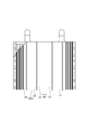
- the separator 20 includes a base portion 21 that is a long sheet and forms the main body of the separator 20, a plurality of ribs 22 formed in the widthwise central portion of the base portion 21, and a plurality of ribs 22 in the width direction of the base portion 21. And a plurality of mini-ribs 23 formed on both sides of the.
- the rib 22 is a convex portion that protrudes from the first surface 21 a, which is one surface of the base 21, and extends in the longitudinal direction of the base 21.
- the plurality of ribs 22 are formed at equal intervals.
- the mini-rib 23 is a convex portion that projects from the first surface 21 a of the base 21, and extends in the longitudinal direction of the base 21.
- the plurality of mini-ribs 23 are formed at equal intervals.
- the rib 22 and the mini-rib 23 are not formed on the second surface 21b, which is the other surface of the base portion 21.
- the separator 20 is cut to an appropriate length, folded in two in the longitudinal direction of the separator 20 so that the first surface 21a is on the outer side (the second surface 21b is on the inner side), and both sides thereof are mechanically formed. It is joined by sealing, pressure bonding or heat welding. Thereby, the bag-shaped separator 11 is obtained.
- the separator 11 may be one that is folded in two in the longitudinal direction of the separator 20 and overlapped with each other, and that both sides thereof are not joined.
- the separator 11 includes a bag-shaped base portion 21, a plurality of convex (for example, linear) ribs 22, and a plurality of convex (for example, linear) mini-ribs 23. ..
- the base portion 21 is folded in two and overlapped, and the joint portions 24 for joining the overlapped base portions 21 are formed at both ends thereof.
- the joint portions 24 are formed on both sides of the plurality of mini ribs 23.
- An opening 25 for inserting the target electrode plate is formed at the upper end of the base 21.
- the rib 22 is formed on the first surface 21a side which is the outer surface of the base portion 21.
- the first surface 21a of the base 21 is an outer surface of the bag and is a surface opposite to the target electrode plate with respect to the base 21.
- the second surface 21 b of the base portion 21 is an inner surface of the bag and is a surface of the target electrode plate side with respect to the base portion 21.
- the rib 22 has a bottom rib portion 22a arranged between the base portion 21 and the bottom portion 31 of the battery case 2. Specifically, the rib 22 is formed so as to straddle the bottom of the target electrode plate, and extends in the vertical direction from the lower end of the base 21 to the upper end of the base 21. For this reason, as shown in FIG.
- the rib 22 projects downward from the lower end of the base portion 21.
- the portion of the rib 22 protruding downward from the lower end of the base portion 21 serves as the bottom rib portion 22a. Therefore, since the separator 11 has the plurality of ribs 22, it also has the plurality of bottom rib portions 22a.
- the shape, position, number, etc. of the rib 22 may be appropriately changed as long as the rib 22 is formed on the first surface 21a side which is the outer surface of the base 21 so as to straddle the bottom of the target electrode plate.
- the plurality of ribs 22 are arranged substantially parallel to each other.
- the distance between the ribs 22 is, for example, 3 to 15 mm.
- One end in the height direction of the rib 22 is integrated with the base portion 21, and the other end in the height direction of the rib 22 is in contact with an electrode plate not housed in the separator 11, that is, the positive electrode plate 9 in this embodiment.
- the height of the rib 22 refers to the height in the direction in which the rib 22 projects with respect to the base portion 21.
- the mini-rib 23 has a function of improving the strength of the separator 11 in order to prevent the corners of the electrodes from breaking through the separator 11 and short-circuiting when the lead storage battery 1 vibrates laterally.
- the height, width, and spacing of the mini-ribs 23 are preferably smaller than that of the ribs 22.
- the cross-sectional shape of the mini-rib 23 may be the same as or different from that of the rib 22.
- the cross-sectional shape of the mini-rib 23 is preferably semicircular.
- the mini-ribs 23 may not be formed in the separator 11.
- the upper limit of the thickness T of the base portion 21 is, for example, 0.25 mm from the viewpoint of obtaining excellent charge acceptability and discharge characteristics. When the thickness T is 0.25 mm or less, charge acceptability and discharge characteristics tend to be improved.
- the upper limit of the thickness T of the base portion 21 is preferably 0.2 mm, more preferably 0.15 mm, from the viewpoint of obtaining further excellent charge acceptability and discharge characteristics.
- the lower limit of the thickness T of the base portion 21 is not particularly limited, but may be 0.05 mm or 0.1 mm from the viewpoint of excellent effect of suppressing a short circuit.
- the upper limit of the height H1 of the rib 22 is preferably 1.25 mm, more preferably 1.0 mm, and even more preferably 0.75 mm from the viewpoint of obtaining excellent charge acceptance.
- the lower limit of the height H1 of the rib 22 is, for example, 0.3 mm, and may be 0.4 mm or 0.5 mm, from the viewpoint of suppressing oxidative deterioration of the positive electrode.
- the thickness of the separator where the rib 22 is provided is, for example, 0.4 to 0.75 mm, 0.4 to 0.7 mm, 0.4 to 0.65 mm, 0.4 to 0.6 mm, 0.5 to 0.75 mm, 0.55 to 0.75 mm, 0.6 to 0.75 mm, or 0.6 to 0.7 mm. May be.
- the lower limit of the ratio H1/T of the height H1 of the rib 22 to the thickness T of the base portion 21 may be 2 or more from the viewpoint of excellent oxidation resistance of the separator.
- the ratio H1/T is 2 or more, a portion that does not contact the electrode (for example, the positive electrode plate 9) can be sufficiently secured, and it is presumed that the oxidation resistance of the separator is improved.
- the lower limit of the ratio H1/T is preferably 2.4 and more preferably 3 from the viewpoint of excellent oxidation resistance and productivity of the separator.
- the upper limit of the ratio H1/T may be 6 from the viewpoint of excellent shape retention of the ribs and the effect of suppressing short circuits.
- the ratio H1/T is 6 or less, the distance between the positive electrode plate 9 and the negative electrode plate 10 is sufficient, and it is presumed that short circuit is suppressed.
- the ratio H1/T is 6 or less, the ribs are not damaged when the lead storage battery 1 is assembled, and the battery characteristics such as charge acceptability are presumed to be maintained well.
- the upper limit of the ratio H1/T is preferably 5, more preferably 4.5, still more preferably 4 from the viewpoint of excellent effect of suppressing a short circuit and the excellent shape retention of the rib.
- the upper bottom width B of the rib 22 is preferably 0.1 to 2 mm, more preferably 0.2 to 1 mm, and 0.2 to 0.8 mm from the viewpoint of excellent shape retention and oxidation resistance of the rib. More preferable.
- the lower bottom width A of the rib 22 is preferably 0.2 to 4 mm, more preferably 0.3 to 2 mm, and even more preferably 0.4 to 1 mm, from the viewpoint of excellent shape retention of the rib.
- the ratio B/A of the upper bottom width B and the lower bottom width A is preferably 0.1 to 1, more preferably 0.2 to 0.8, and 0.3 to 0 from the viewpoint of excellent rib shape retention. 0.6 is more preferable.
- the battery case 2 is a container that houses the electrode plate group 7.
- the inside of the battery case 2 is divided into a plurality of compartments by a plurality of partition walls (not shown) to form a plurality of cell chambers (not shown).
- the cell chamber is a space into which the electrode plate group 7 is inserted.
- the battery case 2 includes a substantially rectangular bottom portion 31 and side portions 32 rising from the four sides (peripheral edges) of the bottom portion 31.
- the upper edge of the side part 32 forms an opening for inserting the electrode plate group 7 into the battery case 2.
- the battery case 2 has a shape such that the base 21 of the separator 11 does not contact the bottom of the battery case 2.
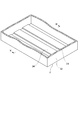
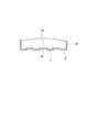
- the battery case 2 has a convex portion 34 protruding from the bottom portion 31 to the inside of the battery case 2.
- the convex portion 34 is preferably formed integrally with the bottom portion 31, but may be formed separately from the bottom portion 31 and joined to the bottom portion 31.
- the convex portion 34 extends in a direction intersecting with the target electrode plate (the negative electrode plate 10 in this embodiment) in a plan view.
- the convex portion 34 may extend in a direction substantially orthogonal to the target electrode plate in plan view.
- the surface shape of the convex portion 34 is not particularly limited.
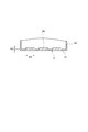
- the surface of the convex portion 34 may be formed in a rectangular shape, a trapezoidal shape, or a circle in a cross section (a cross section shown in FIG. 9) orthogonal to the extending direction of the convex portion 34. It may be formed in a shape. From the viewpoint of suppressing damage to the base portion 21 of the separator 11, it is preferable that the convex portion 34 be formed into a rounded corner in a cross section orthogonal to the extending direction of the convex portion 34. That is, it is preferable that the corners of the convex portion 34 are rounded.
- the radius of the rounded corner of the convex portion 34 (the radius of the rounded corner of the convex portion 34) can be, for example, 0.5 mm or more and 1.0 mm or less.
- the surface of the convex portion 34 is preferably formed in a curved shape from the lower end to the upper end in a cross section orthogonal to the extending direction of the convex portion 34.
- a plurality of convex portions 34 may be formed on the bottom portion 31 of the battery case 2, or only one convex portion 34 may be formed.
- the plurality of protrusions 34 may be arranged at equal intervals or may not be arranged at equal intervals.
- the height H2 of the convex portion 34 is the height H1 of the bottom rib portion 22a of the separator 11. (See FIG. 6). That is, it is preferable that H2 ⁇ H1.
- the height H2 of the convex portion 34 can be made 0.25 mm or more lower than the height H1 of the bottom rib portion 22a, for example.
- the width W2 (see FIG. 9) of the convex portion 34 is the distance between the plurality of bottom rib portions 22a of the separator 11. It is preferably wider than W1 (see FIG. 4). That is, it is preferable that W2>W1.
- the convex portion 34 is preferably formed at a position corresponding to at least a pair of adjacent bottom rib portions 22a. Further, it is preferable that a plurality of convex portions 34 are formed on the bottom portion 31 of the battery case 2 and are arranged at equal intervals.
- the battery case 2 has a shape in which the base 21 of the separator 11 does not stick to the bottom 31 of the battery case 2 when the electrode plate group 7 is inserted into the battery case 2. Therefore, even if the electrode plate group 7 and the bottom 31 of the battery case 2 collide when the electrode plate group 7 is inserted into the battery case 2, it is possible to prevent the base portion 21 of the separator 11 from being damaged by the collision. be able to. This can prevent the separator 11 from being damaged by the collision between the electrode plate group 7 and the bottom 31 of the battery case 2.
- the height H2 of the convex portion 34 is lower than the height H1 of the bottom rib portion 22a, so that the bottom rib portion 22a is convex. Even when the base 21 is not placed on the bottom and falls to the bottom 31, it is possible to prevent the base 21 from coming into contact with the protrusion 34. This can prevent the separator 11 from being damaged by the collision between the electrode plate group 7 and the bottom 31 of the battery case 2.
- the plural convex portions 34 are formed at equal intervals, so that the bottom rib portion 22a is further mounted on the convex portion 34. It is easy to be done.
- the width W2 of the convex portion 34 is wider than the interval W1 between the bottom rib portions 22a of the separator 11, so that the bottom rib portion 22a is convex. It is possible to prevent the base portion 21 from coming into contact with the convex portion 34 by suppressing the falling from the portion 34 to the bottom portion 31. This can prevent the separator 11 from being damaged by the collision between the electrode plate group 7 and the bottom 31 of the battery case 2.
- the plurality of convex portions 34 are formed at equal intervals to further prevent the bottom rib portion 22a from falling from the convex portion 34. Can be suppressed.
- the convex portions 34 are formed into rounded corners, it is possible to prevent the separator 11 from being damaged even if the base portion 21 contacts the convex portions 34.
- the separator 11 is prevented when the base portion 21 contacts the convex portion 34 while suppressing the convex portion 34 from becoming too large. Can be prevented from being damaged.
- the surface of the convex portion 34 is formed in a curved shape from the lower end to the upper end, it is possible to prevent the separator 11 from being damaged even if the base portion 21 contacts the convex portion 34.
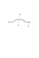
- the bottom portion 31 of the battery case 2 may have a recess 35 that is recessed from the outside of the battery case 2 at a position corresponding to the protrusion 34, and has a uniform thickness.
- the shapes of the convex portion 34 and the concave portion 35 are not particularly limited, and may be, for example, a rectangular shape as shown in FIG. 12 or a curved surface shape as shown in FIG. 13.
- the bottom portion 31 of the battery case 2 has the concave portion 35 that is recessed from the outside of the battery case 2 at a position corresponding to the convex portion 34, so that the bottom portion 31 of the battery case 2 is locally thickened by the convex portion 34. Can be suppressed.
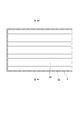
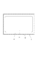
- the bottom portion 31 of the battery case 2 may have a groove portion 37 that is recessed from the inside of the battery case 2 at the end of the bottom portion 31. Since the bottom portion 31 of the battery case 2 has the groove portion 37 recessed from the inside of the battery case 2 at the end of the bottom portion 31, for example, when the outer shape of the battery case 2 is larger than the electrode plate group 7, 2 can be raised. Thereby, the electrode plate group 7 can be appropriately accommodated in the battery case 2 while suppressing an increase in the material of the battery case 2.
- a support rib 39 extending downward from the bottom portion 31 may be provided.
- the bottom portion 31 may be provided with a plurality of linearly extending support ribs 39 arranged in parallel with each other.
- the groove portion 37 may be formed only on a part of the end portion of the bottom portion 31, but as shown in FIG. 15, it is preferably formed on the entire circumferential end portion of the bottom portion 31. Since the groove portion 37 is formed on the entire peripheral edge portion of the bottom portion 31 of the battery case 2, for example, when the outer shape of the battery case 2 is larger than the electrode plate group 7, the increase in the material of the battery case 2 is further suppressed. can do.
- the area of the groove portion 37 may be, for example, 6.0% or more and 10% or less of the area of the bottom portion 31 of the battery case 2.
- the area of the groove portion 37 is set to be 6.0% or more and 10% or less of the area of the bottom portion 31 of the battery case 2, so that the bottom rib portion of the separator 11 is suppressed while suppressing an increase in the material of the battery case 2. 22a can be prevented from falling into the groove portion 37.
- the rib may be formed in a dot shape.
- the ribs 42 shown in FIG. 16 are arranged at predetermined intervals in the vertical direction from the lower end of the base 21 to the upper end of the base 21. In this case, the rib 42 arranged between the base portion 21 and the bottom portion 31 of the battery case 2 becomes the bottom rib portion 42a.
Landscapes
- Engineering & Computer Science (AREA)
- Manufacturing & Machinery (AREA)
- Chemical & Material Sciences (AREA)
- Chemical Kinetics & Catalysis (AREA)
- Electrochemistry (AREA)
- General Chemical & Material Sciences (AREA)
- Cell Separators (AREA)
- Secondary Cells (AREA)
- Sealing Battery Cases Or Jackets (AREA)
Abstract
Description
図1に示すように、鉛蓄電池1は、上面が開口している電槽2と、電槽2の開口を閉じる蓋3とを備えている。電槽2及び蓋3は、例えばポリプロピレンで形成されている。蓋3には、正極端子4と、負極端子5と、蓋3に設けられた注液口を閉塞する液口栓6と、が設けられている。
図2に示すように、極板群7は、複数の正極板9と複数の負極板10とがセパレータ11を介して積層されて構成されている。
セパレータ11は、正極板9と負極板10とを分離する機能を有する。セパレータ11は、電解液(希硫酸)が通過できるように微多孔性を有する。セパレータ11は、微多孔性の樹脂製シートにより作製される。セパレータ11に用いられる樹脂としては、例えば、ポリオレフィンが挙げられる。
電槽2は、極板群7を収容する容器である。電槽2の内部は、複数の隔壁(不図示)によって複数の区画に分割されて、複数のセル室(不図示)が形成されている。セル室は、極板群7が挿入される空間である。極板群7は、単電池とも呼ばれており、起電力は2Vである。自動車用の電装品は、直流電圧12Vを昇圧又は降圧して駆動するため、6個の極板群7を直列に接続して、2V×6=12Vとしている。そのため、鉛蓄電池1を自動車用の電装品として用いる場合、セル室は6個必要となる。なお、鉛蓄電池1を他の用途で用いる場合は、セル室は6個に限定されるものではない。
Claims (12)
- 正極板と負極板とがセパレータを介して積層された極板群と、
前記極板群を収容する電槽と、を備え、
前記正極板又は前記負極板の何れか一方である対象極板を介して隣り合う前記セパレータは、前記対象極板の前記電槽の底部側で繋がっており、
前記セパレータは、基部と、前記基部から突出するリブと、を有し、
前記リブは、前記基部と前記底部との間に配置される底リブ部を有し、
前記電槽は、前記極板群を前記電槽に挿入した際に前記基部が前記底部につかない形状である、
鉛蓄電池。 - 前記電槽は、前記底部から前記電槽の内側に突出して、平面視において前記対象極板と交差する方向に延びる凸部を有し、
前記凸部の高さは、前記底リブ部の高さより低い、
請求項1に記載の鉛蓄電池。 - 前記セパレータは、複数の前記底リブ部を有しており、
前記電槽は、前記底部から前記電槽の内側に突出して、平面視において前記対象極板と交差する方向に延びる凸部を有し、
前記凸部の幅は、前記底リブ部の間隔よりも広い、
請求項1に記載の鉛蓄電池。 - 前記凸部は、等間隔に複数形成されている、
請求項2又は3に記載の鉛蓄電池。 - 前記凸部は、前記凸部の延在方向と直交する断面において、角丸に形成されている、
請求項2~3の何れか一項に記載の鉛蓄電池。 - 前記凸部の角丸の半径(前記凸部の角の丸み半径)は、0.5mm以上1.0mm以下である、
請求項5に記載の鉛蓄電池。 - 前記凸部の表面は、前記凸部の延在方向と直交する断面において、下端から上端まで曲線状に形成されている、
請求項2~6の何れか一項に記載の鉛蓄電池。 - 前記底部は、前記凸部に対応する位置において前記電槽の外側から窪む凹部を有する、
請求項2~7の何れか一項に記載の鉛蓄電池。 - 前記底部は、均一な厚さである、
請求項2~8の何れか一項に記載の鉛蓄電池。 - 前記底部は、前記底部の端部において前記電槽の内側から窪む溝部を有する、
請求項1~9の何れか一項に記載の鉛蓄電池。 - 前記溝部は、前記底部の全周縁部に形成されている、
請求項10に記載の鉛蓄電池。 - 平面視において、前記溝部の面積は、前記底部の面積の6.0%以上10%以下である、
請求項10又は11に記載の鉛蓄電池。
Priority Applications (2)
| Application Number | Priority Date | Filing Date | Title |
|---|---|---|---|
| JP2021501166A JP7282869B2 (ja) | 2019-02-18 | 2019-02-18 | 鉛蓄電池 |
| PCT/JP2019/005899 WO2020170314A1 (ja) | 2019-02-18 | 2019-02-18 | 鉛蓄電池 |
Applications Claiming Priority (1)
| Application Number | Priority Date | Filing Date | Title |
|---|---|---|---|
| PCT/JP2019/005899 WO2020170314A1 (ja) | 2019-02-18 | 2019-02-18 | 鉛蓄電池 |
Publications (1)
| Publication Number | Publication Date |
|---|---|
| WO2020170314A1 true WO2020170314A1 (ja) | 2020-08-27 |
Family
ID=72143778
Family Applications (1)
| Application Number | Title | Priority Date | Filing Date |
|---|---|---|---|
| PCT/JP2019/005899 Ceased WO2020170314A1 (ja) | 2019-02-18 | 2019-02-18 | 鉛蓄電池 |
Country Status (2)
| Country | Link |
|---|---|
| JP (1) | JP7282869B2 (ja) |
| WO (1) | WO2020170314A1 (ja) |
Citations (7)
| Publication number | Priority date | Publication date | Assignee | Title |
|---|---|---|---|---|
| JPS5051121U (ja) * | 1973-09-07 | 1975-05-17 | ||
| JPS5511081U (ja) * | 1978-06-30 | 1980-01-24 | ||
| JPS56112773U (ja) * | 1980-01-29 | 1981-08-31 | ||
| JPS6157466U (ja) * | 1984-09-21 | 1986-04-17 | ||
| JPS627164U (ja) * | 1985-06-28 | 1987-01-16 | ||
| JPS62271369A (ja) * | 1986-05-16 | 1987-11-25 | Honda Motor Co Ltd | 蓄電池 |
| JP2001084988A (ja) * | 1999-09-20 | 2001-03-30 | Shin Kobe Electric Mach Co Ltd | セパレータ及び鉛蓄電池 |
Family Cites Families (3)
| Publication number | Priority date | Publication date | Assignee | Title |
|---|---|---|---|---|
| JPS60146468A (ja) * | 1984-01-10 | 1985-08-02 | Matsushita Electric Ind Co Ltd | 鉛蓄電池 |
| JP2003092098A (ja) * | 2001-09-17 | 2003-03-28 | Shin Kobe Electric Mach Co Ltd | 鉛蓄電池 |
| WO2018147866A1 (en) * | 2017-02-10 | 2018-08-16 | Daramic, Llc | Improved separators with fibrous mat, lead acid batteries, and methods and systems associated therewith |
-
2019
- 2019-02-18 WO PCT/JP2019/005899 patent/WO2020170314A1/ja not_active Ceased
- 2019-02-18 JP JP2021501166A patent/JP7282869B2/ja active Active
Patent Citations (7)
| Publication number | Priority date | Publication date | Assignee | Title |
|---|---|---|---|---|
| JPS5051121U (ja) * | 1973-09-07 | 1975-05-17 | ||
| JPS5511081U (ja) * | 1978-06-30 | 1980-01-24 | ||
| JPS56112773U (ja) * | 1980-01-29 | 1981-08-31 | ||
| JPS6157466U (ja) * | 1984-09-21 | 1986-04-17 | ||
| JPS627164U (ja) * | 1985-06-28 | 1987-01-16 | ||
| JPS62271369A (ja) * | 1986-05-16 | 1987-11-25 | Honda Motor Co Ltd | 蓄電池 |
| JP2001084988A (ja) * | 1999-09-20 | 2001-03-30 | Shin Kobe Electric Mach Co Ltd | セパレータ及び鉛蓄電池 |
Also Published As
| Publication number | Publication date |
|---|---|
| JPWO2020170314A1 (ja) | 2021-12-16 |
| JP7282869B2 (ja) | 2023-05-29 |
Similar Documents
| Publication | Publication Date | Title |
|---|---|---|
| JP7484992B2 (ja) | 蓄電素子 | |
| KR100637443B1 (ko) | 이차 전지와 이에 사용되는 단자 조립체 | |
| KR100860002B1 (ko) | 교번 배향 구조의 이차전지 팩 | |
| JP7024735B2 (ja) | 蓄電装置 | |
| US20120295150A1 (en) | Battery module and method of manufacturing the same | |
| US20170365839A1 (en) | Energy storage device | |
| KR101222369B1 (ko) | 배터리 및 이를 포함한 배터리 팩 | |
| JP6221778B2 (ja) | 蓄電装置 | |
| KR102055852B1 (ko) | 변형된 리드를 구비한 파우치형 이차전지 및 이를 포함하는 전지 모듈 | |
| KR102397122B1 (ko) | 전지 모듈 | |
| JP2009277604A (ja) | 非水電解質二次電池 | |
| KR102052328B1 (ko) | 파우치 셀을 위한 벽관통형 집전 장치 | |
| KR102214538B1 (ko) | 단위전지모듈 및 이를 포함하는 전지모듈 | |
| JP2020520074A (ja) | 溶接用柱を含む円筒型二次電池 | |
| KR101854792B1 (ko) | 전지, 및 이 전지를 구비한 장치 | |
| JP2013161516A (ja) | 組電池 | |
| JP2018195378A (ja) | 蓄電装置 | |
| WO2018140713A1 (en) | Battery grid | |
| JP2013020731A (ja) | 二次電池 | |
| US20130130104A1 (en) | Current collector, energy storage element, and method of manufacturing current collector | |
| KR100904375B1 (ko) | 퓨즈 장착 전지 카트리지와 그것을 포함하는 전지 모듈 | |
| JP3775356B2 (ja) | ラミネート電池および組電池 | |
| KR102113156B1 (ko) | 배터리 모듈 | |
| JP7282869B2 (ja) | 鉛蓄電池 | |
| JP2008243410A (ja) | 密閉型二次電池および電池モジュール |
Legal Events
| Date | Code | Title | Description |
|---|---|---|---|
| 121 | Ep: the epo has been informed by wipo that ep was designated in this application |
Ref document number: 19916006 Country of ref document: EP Kind code of ref document: A1 |
|
| ENP | Entry into the national phase |
Ref document number: 2021501166 Country of ref document: JP Kind code of ref document: A |
|
| NENP | Non-entry into the national phase |
Ref country code: DE |
|
| 32PN | Ep: public notification in the ep bulletin as address of the adressee cannot be established |
Free format text: NOTING OF LOSS OF RIGHTS PURSUANT TO RULE 112(1) EPC (EPO FORM 1205A DATED 11.11.2021) |
|
| 122 | Ep: pct application non-entry in european phase |
Ref document number: 19916006 Country of ref document: EP Kind code of ref document: A1 |