WO2020166360A1 - 空気調和機 - Google Patents
空気調和機 Download PDFInfo
- Publication number
- WO2020166360A1 WO2020166360A1 PCT/JP2020/003520 JP2020003520W WO2020166360A1 WO 2020166360 A1 WO2020166360 A1 WO 2020166360A1 JP 2020003520 W JP2020003520 W JP 2020003520W WO 2020166360 A1 WO2020166360 A1 WO 2020166360A1
- Authority
- WO
- WIPO (PCT)
- Prior art keywords
- expansion valve
- refrigerant
- compressor
- injection
- heat exchanger
- Prior art date
- Legal status (The legal status is an assumption and is not a legal conclusion. Google has not performed a legal analysis and makes no representation as to the accuracy of the status listed.)
- Ceased
Links
Images




Classifications
-
- F—MECHANICAL ENGINEERING; LIGHTING; HEATING; WEAPONS; BLASTING
- F24—HEATING; RANGES; VENTILATING
- F24F—AIR-CONDITIONING; AIR-HUMIDIFICATION; VENTILATION; USE OF AIR CURRENTS FOR SCREENING
- F24F11/00—Control or safety arrangements
- F24F11/70—Control systems characterised by their outputs; Constructional details thereof
- F24F11/80—Control systems characterised by their outputs; Constructional details thereof for controlling the temperature of the supplied air
- F24F11/86—Control systems characterised by their outputs; Constructional details thereof for controlling the temperature of the supplied air by controlling compressors within refrigeration or heat pump circuits
-
- F—MECHANICAL ENGINEERING; LIGHTING; HEATING; WEAPONS; BLASTING
- F25—REFRIGERATION OR COOLING; COMBINED HEATING AND REFRIGERATION SYSTEMS; HEAT PUMP SYSTEMS; MANUFACTURE OR STORAGE OF ICE; LIQUEFACTION SOLIDIFICATION OF GASES
- F25B—REFRIGERATION MACHINES, PLANTS OR SYSTEMS; COMBINED HEATING AND REFRIGERATION SYSTEMS; HEAT PUMP SYSTEMS
- F25B1/00—Compression machines, plants or systems with non-reversible cycle
-
- F—MECHANICAL ENGINEERING; LIGHTING; HEATING; WEAPONS; BLASTING
- F25—REFRIGERATION OR COOLING; COMBINED HEATING AND REFRIGERATION SYSTEMS; HEAT PUMP SYSTEMS; MANUFACTURE OR STORAGE OF ICE; LIQUEFACTION SOLIDIFICATION OF GASES
- F25B—REFRIGERATION MACHINES, PLANTS OR SYSTEMS; COMBINED HEATING AND REFRIGERATION SYSTEMS; HEAT PUMP SYSTEMS
- F25B13/00—Compression machines, plants or systems, with reversible cycle
Definitions
- the present disclosure relates to an air conditioner.
- a liquid refrigerant is prevented from flowing into the compressor by closing an expansion valve or an electromagnetic valve of the injection circuit at the same time when the compressor is stopped. There is.
- the liquid refrigerant was introduced to the compressor, and the oil present in the sliding parts such as the piston inside the compressor was washed out, causing poor lubrication. Further, there is a problem in that the liquid refrigerant stays inside the cylinder of the compressor, so that liquid compression occurs at the time of starting the compressor, and the reliability of the compressor is impaired.
- an electromagnetic on-off valve that can be closed instantly can be provided in the injection circuit, and the electromagnetic on-off valve can be closed at the same time as the compressor stops. Will be high.
- the present disclosure proposes a technique capable of improving the reliability of the compressor in the air conditioner having the injection circuit.
- the air conditioner of the present disclosure has a refrigerant circuit, an injection circuit, and control means.
- a refrigerant pipe is connected so that the refrigerant flows in the order of the compressor, the indoor heat exchanger, the expansion valve, and the outdoor heat exchanger during the heating operation.
- the injection circuit is connected to the compressor from the downstream side of the condenser via the injection expansion valve.
- the control means controls the expansion valve and the injection expansion valve so that the opening of the injection expansion valve is fully closed when the compressor is instructed to stop and the injection expansion valve is open. In the process, the compressor is stopped after reaching a predetermined opening.
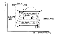
- FIG. 3 is a Mollier diagram (ph diagram) relating to the refrigerant circuit of FIG. 2. It is a figure explaining the refrigerant circuit which has an injection circuit.
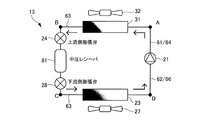
- FIG. 5 is a Mollier diagram (ph diagram) relating to the refrigerant circuit of FIG. 4. It is a figure explaining the refrigerant circuit provided with the intermediate pressure receiver in the air conditioner of the embodiment of this indication.
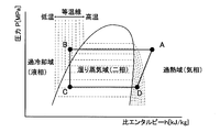
- FIG. 7 is a Mollier diagram (ph diagram) relating to the refrigerant circuit of FIG. 6.
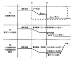
- FIG. 4 is a timing chart (No. 1) showing the operation of the air conditioner of the embodiment of the present disclosure.
- 5 is a timing chart (No. 2) showing the operation of the air conditioner of the embodiment of the present disclosure.
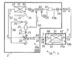
- an air conditioner 1 includes an outdoor unit 2 installed outdoors and an indoor unit 3 installed indoors and connected to the outdoor unit 2 by a liquid pipe 4 and a gas pipe 5. Equipped with. Specifically, the liquid-side shutoff valve 25 of the outdoor unit 2 and the liquid pipe connecting portion 33 of the indoor unit 3 are connected by the liquid pipe 4. Further, the gas side closing valve 26 of the outdoor unit 2 and the gas pipe connecting portion 34 of the indoor unit 3 are connected by the gas pipe 5. As described above, the refrigerant circuit 10 of the air conditioner 1 is formed.
- the outdoor unit 2 includes a compressor 21, a four-way valve 22, an outdoor heat exchanger 23, an upstream expansion valve 24 during heating operation, a liquid side closing valve 25 to which the liquid pipe 4 is connected, and a gas pipe 5. Is connected to the gas side closing valve 26, the outdoor fan 27, the downstream expansion valve 28 during the heating operation, the injection expansion valve 29, the intermediate pressure receiver 81, and the inter-refrigerant heat exchanger 82.
- the respective devices except the outdoor fan 27 are connected to each other by respective refrigerant pipes described later to form an outdoor unit refrigerant circuit 10a forming a part of the refrigerant circuit 10.
- An accumulator (not shown) may be provided on the refrigerant suction side of the compressor 21.
- injection may be described as "INJ.”
- the compressor 21 is a variable capacity compressor whose operating capacity can be changed by controlling the rotation speed by an inverter (not shown).
- the refrigerant discharge side of the compressor 21 is connected to the port a of the four-way valve 22 by a discharge pipe 61.
- the refrigerant suction side of the compressor 21 is connected to the port c of the four-way valve 22 by a suction pipe 66.
- the intermediate pressure receiver 81 is provided in the outdoor unit liquid pipe 63 between the liquid side closing valve 25 and the outdoor heat exchanger 23, sandwiched between the upstream expansion valve 24 and the downstream expansion valve 28.
- the medium pressure receiver 81 is for adjusting the amount of refrigerant to an appropriate amount, even if the indoor units 3 of various sizes are connected.
- An injection pipe (also referred to as an injection circuit) 65 is branched on the downstream side of the intermediate pressure receiver 81, and the injection pipe 65 is connected to an intermediate portion of a cylinder (not shown) inside the compressor 21 via an injection expansion valve 29. There is.
- the injection pipe 65 is used to inject the refrigerant into the compressor 21 in order to increase the refrigerant circulation amount of the condenser (indoor heat exchanger 31 during the heating operation) or lower the discharge temperature of the compressor 21.
- An inter-refrigerant heat exchanger 82 that exchanges heat between the refrigerant flowing through the injection pipe 65 and the refrigerant flowing through the outdoor unit liquid pipe 63 is provided in the middle of the injection pipe 65.
- a series of circuits including the injection pipe 65 and the injection expansion valve 29 is referred to as an injection circuit (in this specification, the injection pipe 65 is a representative example of an injection circuit.
- the injection circuit shown here is an example. And may be other aspects).
- the injection expansion valve 29 can be fully closed, is provided as an opening/closing means of the injection pipe 65, and controls the discharge temperature or the discharge SH of the compressor 21.
- the four-way valve 22 is a valve for switching the flowing direction of the refrigerant, and has four ports a, b, c, d.
- the port a is connected to the refrigerant discharge side of the compressor 21 by the discharge pipe 61 as described above.
- the port b is connected to one refrigerant inlet/outlet of the outdoor heat exchanger 23 by a refrigerant pipe 62.
- the port c is connected to the refrigerant suction side of the compressor 21 by the suction pipe 66 as described above.
- the port d is connected to the gas side closing valve 26 by the outdoor unit gas pipe 64.
- the four-way valve 22 is the flow path switching unit of the present disclosure.
- the outdoor heat exchanger 23 exchanges heat between the refrigerant and the outside air taken into the outdoor unit 2 by the rotation of an outdoor fan 27 described later.
- one refrigerant inlet/outlet of the outdoor heat exchanger 23 is connected to the port b of the four-way valve 22 by the refrigerant pipe 62, and the other refrigerant inlet/outlet is connected to the liquid side closing valve 25 and the outdoor unit liquid pipe 63.
- the outdoor heat exchanger 23 functions as a condenser during cooling and functions as an evaporator during heating operation by switching the four-way valve 22 described later.
- the upstream expansion valve 24 and the downstream expansion valve 28 during heating operation are electronic expansion valves driven by a pulse motor (not shown). Specifically, the opening degree is adjusted by the number of pulses applied to the pulse motor. The opening degree of the upstream expansion valve 24 is adjusted so that SC reaches a predetermined target value. Further, the opening degree of the downstream expansion valve 28 is adjusted so that the discharge temperature, which is the temperature of the refrigerant discharged from the compressor 21, reaches a predetermined target temperature during the heating operation.
- the outdoor fan 27 is made of a resin material and is arranged near the outdoor heat exchanger 23.
- the outdoor fan 27 is connected at its center to a rotating shaft of a fan motor (not shown).
- the outdoor fan 27 rotates as the fan motor rotates.
- the outside air is taken into the inside of the outdoor unit 2 from the suction port (not shown) of the outdoor unit 2, and the outside air that has exchanged heat with the refrigerant in the outdoor heat exchanger 23 is discharged from the outlet (not shown) of the outdoor unit 2 to the outside. Discharge to the outside of machine 2.
- the outdoor unit 2 is provided with various sensors. As shown in FIG. 1A, a discharge pressure sensor 71 that detects the pressure of the refrigerant discharged from the compressor 21 and a temperature of the refrigerant discharged from the compressor 21 (the above-described discharge temperature) are detected in the discharge pipe 61.
- the discharge temperature sensor 73 is provided in the suction pipe 66.
- a suction pressure sensor 72 for detecting the pressure of the refrigerant sucked into the compressor 21 and a suction temperature sensor 74 for detecting the temperature of the refrigerant sucked into the compressor 21 are connected to the outdoor unit liquid pipe 63.
- a heat exchange temperature sensor 75 for detecting the outdoor heat exchange temperature, which is the temperature of the outdoor heat exchanger 23, is provided at a substantially middle portion of a refrigerant path (not shown) of the outdoor heat exchanger 23.
- An outdoor air temperature sensor 76 that detects the temperature of the outdoor air flowing into the outdoor unit 2, that is, the outdoor air temperature is provided near the suction port (not shown) of the outdoor unit 2.
- the outdoor unit 2 is provided with the outdoor unit control means 200.
- the outdoor unit control means 200 is mounted on a control board stored in an electric component box (not shown) of the outdoor unit 2.
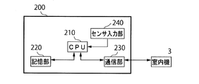
- the outdoor unit control unit 200 includes a CPU 210, a storage unit 220, a communication unit 230, and a sensor input unit 240 (in this specification, the outdoor unit control unit 200 is simply referred to as the outdoor unit control unit 200. Sometimes called control means).
- the storage unit 220 is composed of a flash memory, and stores a control program of the outdoor unit 2, detection values corresponding to detection signals from various sensors, control states of the compressor 21, the outdoor fan 27, and the like. Although not shown, the storage unit 220 stores in advance a rotation speed table that defines the rotation speed of the compressor 21 according to the required capacity received from the indoor unit 3.
- the communication unit 230 is an interface that communicates with the indoor unit 3.
- the sensor input unit 240 takes in the detection results of the various sensors of the outdoor unit 2 and outputs them to the CPU 210.
- the CPU 210 fetches the detection result of each sensor of the outdoor unit 2 described above via the sensor input unit 240. Further, the CPU 210 takes in the control signal transmitted from the indoor unit 3 via the communication unit 230. The CPU 210 controls the drive of the compressor 21 and the outdoor fan 27 based on the captured detection result, control signal, and the like. In addition, the CPU 210 controls the switching of the four-way valve 22 based on the captured detection result and the control signal. Further, the CPU 210 performs opening adjustment of the upstream expansion valve 24 and downstream expansion valve 28, opening/closing control of the injection expansion valve 29, and opening adjustment based on the captured detection result and control signal.
- the CPU 210 is provided with a liquid storage determination unit that determines whether or not the liquid refrigerant is stored in the medium pressure receiver 81.
- the liquid storage determination unit is provided in the medium pressure receiver 81, as will be described later in detail.
- the injection expansion valve 29 is opened to inject the refrigerant to the intermediate pressure of the compressor 21.
- the indoor unit 3 includes an indoor heat exchanger 31, an indoor fan 32, a liquid pipe connecting portion 33 to which the other end of the liquid pipe 4 is connected, and a gas pipe connecting portion 34 to which the other end of the gas pipe 5 is connected. I have it.
- the respective devices except the indoor fan 32 are connected to each other by respective refrigerant pipes described in detail below to form an indoor unit refrigerant circuit 10b forming a part of the refrigerant circuit 10.
- the indoor heat exchanger 31 heat-exchanges the indoor air taken into the indoor unit 3 from the suction port (not shown) of the indoor unit 3 by the rotation of the refrigerant and the indoor fan 32 described later.
- One of the refrigerant inlet/outlet ports of the indoor heat exchanger 31 is connected to the liquid pipe connecting portion 33 by the indoor unit liquid pipe 67.
- the other refrigerant inlet/outlet of the indoor heat exchanger 31 is connected to the gas pipe connecting portion 34 by an indoor unit gas pipe 68.
- the indoor heat exchanger 31 functions as an evaporator when the indoor unit 3 performs a cooling operation, and functions as a condenser when the indoor unit 3 performs a heating operation.
- the indoor fan 32 is made of a resin material and is arranged near the indoor heat exchanger 31.
- the indoor fan 32 is rotated by a fan motor (not shown) to take in the indoor air from the suction port (not shown) of the indoor unit 3 into the interior of the indoor unit 3, and to exchange the indoor air with the refrigerant in the indoor heat exchanger 31 into the indoor air.
- the air is blown out into the room from an air outlet (not shown) of the machine 3.
- the indoor unit 3 is provided with various sensors.
- the indoor unit liquid pipe 67 is provided with a liquid side temperature sensor 77a that detects the temperature of the refrigerant flowing into or out of the indoor heat exchanger 31.
- the indoor unit gas pipe 68 is provided with a gas side temperature sensor 78 that detects the temperature of the refrigerant flowing out from the indoor heat exchanger 31 or flowing into the indoor heat exchanger 31.
- the CPU 210 causes the four-way valve 22 to be in a state shown by a solid line as shown in FIG. 1A, that is, so that the port a and the port d of the four-way valve 22 communicate with each other, and Switch so that c communicates.
- the refrigerant circulates in the refrigerant circuit 10 in the direction indicated by the solid line arrow, and the outdoor heat exchanger 23 functions as an evaporator, and the indoor heat exchanger 31 functions as a condenser, which is a heating cycle.
- the high-pressure refrigerant discharged from the compressor 21 flows through the discharge pipe 61 and flows into the four-way valve 22.
- the refrigerant flowing into the port a of the four-way valve 22 flows through the outdoor unit gas pipe 64 from the port d of the four-way valve 22 and flows into the gas pipe 5 via the gas side closing valve 26.
- the refrigerant flowing through the gas pipe 5 flows into the indoor unit 3 via the gas pipe connecting portion 34.
- the refrigerant flowing into the indoor unit 3 flows through the indoor unit gas pipe 68, flows into the indoor heat exchanger 31, and exchanges heat with the indoor air taken into the indoor unit 3 by the rotation of the indoor fan 32 to condense. To do.
- the indoor heat exchanger 31 functions as a condenser, and the indoor air that has exchanged heat with the refrigerant in the indoor heat exchanger 31 is blown out into the room from an outlet (not shown), so that the indoor unit 3 is installed.
- the heated room is heated.
- the refrigerant flowing out of the indoor heat exchanger 31 flows through the indoor unit liquid pipe 67, and then flows into the liquid pipe 4 via the liquid pipe connecting portion 33.
- the refrigerant flowing through the liquid pipe 4 and flowing into the outdoor unit 2 via the liquid side closing valve 25 flows through the outdoor unit liquid pipe 63 and passes through the upstream expansion valve 24, the intermediate pressure receiver 81, and the downstream expansion valve 28.
- the opening degree of the upstream expansion valve 24 is set so that the degree of supercooling (SC) of the refrigerant after the indoor heat exchanger 31 flows out becomes a predetermined target value.
- the opening degree of 28 is adjusted so that the discharge temperature of the compressor 21 reaches a predetermined target value, or the suction superheat degree (intake SH) of the refrigerant sucked into the compressor 21 reaches a predetermined target value. Is adjusted to
- the refrigerant that has passed through the upstream expansion valve 24, the intermediate pressure receiver 81, and the downstream expansion valve 28 and has flowed into the outdoor heat exchanger 23 exchanges heat with the outside air taken into the outdoor unit 2 by the rotation of the outdoor fan 27. To evaporate.
- the refrigerant flowing from the outdoor heat exchanger 23 to the refrigerant pipe 62 flows through the ports b and c of the four-way valve 22 and the suction pipe 66, is sucked into the compressor 21 and is compressed again.
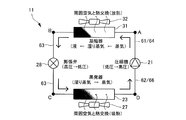
- the basic refrigerant circuit 11 will be described with reference to FIGS. 2 and 3.
- the point A is between the compressor 21 and the condenser (corresponding to the indoor heat exchanger 31 during the heating operation.
- the point C is the expansion valve 28 and the evaporator (the outdoor heat exchanger 23 during the heating operation).
- the point D indicates between the evaporator 23 and the compressor 21 (hereinafter the same as the evaporator 23) (hereinafter the same).
- the state of the refrigerant from point A to point D, or between each point, is as follows, as shown in FIG. (1)
- the refrigerant (between points D and A) in the compression process in the compressor 21 is compressed, and both the pressure (vertical axis) and the temperature rise to become high-temperature high-pressure superheated vapor (by heat exchange with ambient air. It becomes easy to condense).
- the refrigerant (point A) discharged from the compressor 21 is a superheated high-pressure gas-phase refrigerant.
- the refrigerant (between points A and B) in the condensation process in the condenser 31 exchanges heat (radiates heat) with the ambient air so that the pressure remains constant and superheated steam, saturated steam, wet steam, saturated liquid After each of the above states, it becomes a high-pressure supercooled liquid.
- the refrigerant (point B) flowing out from the condenser 31 is a high-pressure liquid-phase refrigerant in a supercooled state.
- the refrigerant (between points B and C) in the expansion process in the expansion valve 28 expands and both the pressure (vertical axis) and the temperature decrease to become wet vapor (it is easy to evaporate by heat exchange with ambient air). State).
- the refrigerant in the evaporation process in the evaporator 23 exchanges heat with the ambient air (endothermic heat), so that the pressure remains constant and the refrigerant passes through the wet steam and saturated steam states. It becomes low pressure superheated steam.
- the refrigerant (point D) flowing out from the evaporator 23 is a superheated low-pressure gas-phase refrigerant.
- the control method of the compressor 21, the indoor fan 32, the expansion valve 28, and the outdoor fan 27, which are the objects to be controlled in this basic refrigerant circuit 11, is as follows.
- the indoor fan 32 is controlled according to the difference between the room temperature and the set temperature during heating operation (when the condenser is the indoor heat exchanger 31) and during cooling operation (when the condenser is the outdoor heat exchanger 23), or by the user.
- the air volume is set to your preference.
- the expansion valve 28 is controlled so that the temperature of the point A (discharge temperature) reaches a target value (discharge temperature control), or a control amount (pulse) predetermined according to the amount of change in the rotation speed of the compressor 21.
- the expansion valve 28 is controlled by a control for adjusting the opening degree (rotational speed pulse control).
- the discharge temperature control is a feedback control that adjusts the opening degree after a disturbance such as the room temperature or the outside air temperature appears in the change in the discharge temperature, whereas the rotation speed pulse control circulates from the change amount of the rotation speed. This is a feedforward control in which the amount of change in the amount is predicted and the expansion valve 28 is adjusted in advance so as to have an appropriate opening.
- the outdoor fan 27 is controlled based on the rotation speed of the compressor 21 both during heating operation (when the evaporator is on the heat source side) and during cooling operation (when the evaporator is on the use side).
- the basic operational restrictions in the refrigerant circuit 11 are as follows.
- the reason is that when the two-phase refrigerant flows into the expansion valve 28, inconveniences such as generation of refrigerant flow noise and deterioration of controllability occur.
- the refrigerant circuit 12 having the injection circuit 65 will be described with reference to FIGS. 4 and 5. As shown in FIG. 4, in the refrigerant circuit 12 having the injection circuit 65, a part of the refrigerant after flowing out from the condenser 31 is caused to flow into the intermediate pressure of the compressor 21.
- the injection circuit 65 includes an injection expansion valve 29 that adjusts the amount of refrigerant injected into the compressor 21, and an inter-refrigerant heat exchanger 82 (SC heat exchanger) to increase the dryness of the injected refrigerant.
- SC heat exchanger inter-refrigerant heat exchanger
- points E to G are added in addition to points A to D, and the point E is the outdoor unit liquid pipe 63 side flow path outlet of the inter-refrigerant heat exchanger 82.
- a point F between the injection expansion valve 29 and the injection circuit 65 side flow path inlet of the inter-refrigerant heat exchanger 82, and a point G is the injection circuit 65 side flow path outlet of the inter-refrigerant heat exchanger 82. It refers to between the compressors 21 (same below).
- the purpose of the injection circuit 65 is to increase the refrigerant circulation amount of the condenser 31 (to increase the heating capacity during low outside air (-20 to -30°C) heating operation, etc.) and to lower the discharge temperature of the compressor 21. (By setting the evaporation temperature lower than the outside air temperature during a low outside air heating operation, the temperature of the compressor 21 does not become an abnormal temperature even if the pressure difference between the high pressure (condensing pressure) and the low pressure (evaporation pressure) becomes large. It is that).
- the state of the refrigerant in the refrigerant circuit 12 is as shown in FIG. 5, but the difference from the refrigerant circuit 11 is as follows.
- (1) Between points D to A of the compression process in the compressor 21, a part of the refrigerant in the condensation process flows into the intermediate pressure of the compressor 21 in a two-phase state via the injection circuit 65, and The temperature of the refrigerant compressed in 21 decreases during the compression, and the discharge temperature at point A decreases as compared with the case where the refrigerant is not circulated in the injection circuit 65.
- the refrigerant passes between points A and B in the condensation process and becomes a liquid state, and then flows between points F and G of the injection circuit 65 between points B and E and the heat exchanger between refrigerants.
- the heat is exchanged and supercooled by 82.
- the refrigerant flowing between B and E is heat-exchanged by the inter-refrigerant heat exchanger 82 to increase the dryness, and is injected from the point G to the points D to A of the compression process.
- the control method of the expansion valve 28 and the injection expansion valve 29, which are characteristic objects of control in the refrigerant circuit 12, is as follows.
- the expansion valve 28 controls the temperature at point A (discharge temperature) to reach a target value (discharge temperature control), and is determined in advance according to the amount of change in the rotation speed of the compressor 21.
- Control rotation speed pulse control
- Control rotation speed pulse control
- the injection expansion valve 29 is closed when injection is not performed.
- control is performed so that the temperature at point A (discharge temperature) or discharge SH reaches a target value (discharge temperature control or discharge SH control).
- the refrigerant circuit 13 including the intermediate pressure receiver 81 will be described with reference to FIGS. 6 and 7. As shown in FIG. 6, the reference points of the refrigerant circuit 13 are points A to D as in the basic refrigerant circuit 11.
- the purpose of the medium pressure receiver 81 is to adjust the amount of refrigerant to an appropriate amount, regardless of the size of the indoor unit 3 to be connected. This corresponds to the fact that the amount of refrigerant required for the refrigerant circuit 13 differs depending on the size of the indoor heat exchanger 31 and the length of the pipes (internal volume) at various places.
- the required amount of refrigerant is different means that the amount of refrigerant required for efficient and reliable operation (appropriate intake SH, SC) is the size of the indoor heat exchanger and the length of the connecting pipe. It means that there is a difference in volume due to such a difference, and the inside of the medium-pressure receiver 81 is adjusted by letting the refrigerant therein into and out of the refrigerant circuit 13.
- the refrigerant circuit 13 having the intermediate pressure receiver 81 includes the intermediate pressure receiver 81 between the condenser 31 and the evaporator 23, and the upstream side expansion valve 24 and the upstream expansion valve 24 are provided on the upstream side and the downstream side of the intermediate pressure receiver 81, respectively.
- a downstream expansion valve 28 is provided.
- the state of the refrigerant in the refrigerant circuit 13 is substantially the same as that of the basic refrigerant circuit 11, as shown in FIG. 7.
- the control method of the upstream side expansion valve 24 and the downstream side expansion valve 28, which are characteristic control objects in the refrigerant circuit 13, are as follows.
- SC SC control
- the refrigerant circuit 10 includes both the injection circuit 65 and the intermediate pressure receiver 81 described above.
- FIG. 8 shows the refrigerant circuit 10 by simplifying FIGS. 1A and 1B.
- the refrigerant circuit 12 having the injection circuit 65 of FIG. 4 upstream expansion before the injection circuit 65 branches (upstream side). This is a mode in which the valve 24 and the intermediate pressure receiver 81 are provided.
- the expansion valve 28 in FIG. 4 becomes the downstream expansion valve 28.
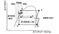
- a point H is added in addition to the points A to D and points E to G, and the point H is between the upstream expansion valve 24 and the intermediate pressure receiver 81. Point to.
- the state of the refrigerant in the refrigerant circuit 10 is as shown in FIG. 9, but the points different from the refrigerant circuit 12 are as follows. (1) The pressure of the refrigerant decreases after passing through points A and B in the condensation process through the upstream expansion valve 24 between points B and H, and then between points H and E at point F of the injection circuit 65. Heat is exchanged between G and G by the heat exchanger 82 between refrigerants. (2) The pressure of the refrigerant flowing into the injection circuit 65 branched from the point H between the points A to E is reduced via the injection expansion valve 29 between the points H and F, and then the point B between the points F and G. To E and heat is exchanged by the heat exchanger 82 between refrigerants to increase the dryness, and injection is performed from the point G to the points D to A in the compression process.
- FIG. 10 shows the stop instruction (R1) to the compressor 21, the rotation speed (R2) of the compressor 21, the rotation speed (R3) of the outdoor fan 27, the condenser (the indoor heat exchanger 31 during the heating operation) EEV (heating).
- FIG. 11 shows the opening degree (R5) of the evaporator (the outdoor heat exchanger 23 during the heating operation) EEV (the downstream expansion valve 28 during the heating operation).
- INJEEEV injection expansion valve 29
- R7 the rotational speed
- FIGS. 10 and 11 mainly describe the processes related to the present disclosure, and other processes, for example, control of the refrigerant circuit 100 corresponding to operating conditions such as set temperature and air volume instructed by the user.
- the description of the general processing related to the air conditioner 1, such as the above, is omitted.
- the rotation speed of the compressor 21 (R1) and the rotation speed of the outdoor fan 27 (R2).
- the opening degree (R3) of the upstream expansion valve 24 and the downstream expansion valve 28, the injection expansion valve 29 (R4), and the rotation speed (R5) of the indoor fan 32 are normally controlled.
- the normal control of the rotation speed of the compressor 21 is the control of driving the compressor 21 at the rotation speed determined based on the capacity required on the indoor unit 3 side, as described above.
- the normal control of the rotation speed of the outdoor fan 27 is, as described above, a control that makes the rotation speed of the outdoor fan 27 correspond to the rotation speed of the compressor 21 (fan rotation speed control).
- the normal control of the opening degrees of the upstream expansion valve 24 and the downstream expansion valve 28 is control for adjusting the opening degrees by a predetermined control amount (pulse) according to the rotational speed change amount of the compressor 21. (Rotation speed pulse control). Further, the normal control of the opening degree of the injection expansion valve 29 is the discharge temperature control or the discharge SH control, as described above. As described above, the indoor fan 32 is controlled according to the difference between the room temperature and the set temperature, or is set by the user so as to have a desired air volume.
- R2 to R7 are controlled as follows, respectively.
- the rotation speed (R1) of the compressor 21 is controlled to the minimum rotation speed (Arps) by OFF control, and the opening degree (R6) of the injection expansion valve 29 described later is a predetermined opening degree (in FIG. 11, a fully closed pulse). At the timing T2 at which it becomes 0 rps, that is, it stops. This point will be described later in detail.
- the rotation speed (R2) of the outdoor fan 27 decreases with the instruction to stop the compressor 21 at the timing T1 by the above-described fan rotation speed control. At this time, the rotation speed (R2) of the outdoor fan 27 maintains a constant rotation speed corresponding to the rotation speed of the compressor 21 at the timing when the rotation speed (R1) of the compressor 21 becomes the minimum rotation speed (Arps). Then, after the rotation speed (R1) of the compressor 21 becomes 0 rps at the timing T2, it becomes 0 rpm after a fixed time, that is, the compressor 21 stops.
- This fixed time is a time that is a standard for completing the pressure equalization of the refrigerant circuit 10.
- the fixed time is set longer as the internal volume of the refrigerant circuit 10 increases.
- the fixed time can be set arbitrarily, but in FIG. 10, it is set to 60 seconds as an example.
- the opening degree (R3) of the upstream expansion valve 24 and the downstream expansion valve 28 is reduced by the above-described rotation speed pulse control in accordance with the instruction to stop the compressor 21 at the timing T1.
- the opening degree (R3) of each expansion valve becomes the opening degree corresponding to the rotation speed of the compressor 21, Even after the rotational speed (R1) of 21 becomes 0 rps at the timing T2, the opening degree is maintained for a certain period of time.
- This fixed time can be set arbitrarily by the control when the compressor 21 is OFF, but in FIG. 10, the opening degree is set for several tens of seconds longer than the time when the rotation speed (R2) of the outdoor fan 27 is maintained.
- the pulse is fixed.
- the timing T2 there is a large difference between the pressure of the refrigerant on the high pressure side of the refrigerant circuit (the indoor heat exchanger 31 side during the heating operation) and the pressure of the refrigerant on the low pressure side of the refrigerant circuit 10. Therefore, when the opening degree (R3) of each expansion valve is increased, a large amount of refrigerant passes through each expansion valve due to the pressure difference, and thus noise due to refrigerant flowing noise becomes a problem. Therefore, the fixed time period is set to be longer than at least the time period during which the rotation speed (R2) of the outdoor fan 27 is maintained (the time period that is a standard for completing the pressure equalization of the refrigerant circuit 10).
- each expansion valve is shifted to a fully open state after a lapse of a certain period of time to further promote the pressure equalization of the refrigerant circuit 10.
- the opening degree (R4) of the injection expansion valve 29 is reduced by the OFF control in accordance with the instruction to stop the compressor 21 at the timing T1. Then, at timing T2, the opening degree of the injection expansion valve 29 reaches a predetermined opening degree (in FIG. 11, a fully closed pulse). At this timing T2, as described above, the rotation speed (R1) of the compressor 21 is 0 rps, that is, the compressor 21 is stopped. This point will be described later in detail.
- the rotation speed (R5) of the indoor fan 32 is stopped at timing T1 as part of normal control in accordance with the instruction to stop the compressor 21 at timing T1.
- the rotation speed (R1) of the compressor 21 is reduced to the minimum rotation speed (Arps).
- the compressor 21 is stopped after the opening degree of the injection expansion valve 29 reaches a predetermined opening degree in the process of lowering the opening degree and thereafter controlling the opening degree of the injection expansion valve 29 to be fully closed.
- the minimum rotation speed (Arps) is the heating speed when the compressor 21 whose rotation speed is decreasing in response to the stop instruction to the compressor 21 is operated at the rotation speed before receiving the stop instruction.
- the rotation speed (R5) of the indoor fan 32 is also sequentially decreased, the refrigerant is flowing through the indoor unit 3, so that comfort such as overheating of the room is deteriorated.
- the rotation speed (R5) of the indoor fan 32 is set to 0 rpm and stopped, the high pressure increases and the durability of the parts may be impaired. Therefore, in the process in which the opening degree of the injection expansion valve 29 is controlled to be fully closed, the minimum rotation speed (Arps) within the operable range of the compressor 21 is maintained until a predetermined opening degree is reached. Is desirable.
- the rotation speed (R1) of the compressor 21 changes from the minimum rotation speed (Arps) to 0 rps, that is, the timing T2 at which the compressor 21 is stopped is a process in which the opening degree of the injection expansion valve 29 is controlled to be fully closed.
- the injection expansion valve 29 can be fully closed as described above, and therefore a fully closed state may be adopted as the predetermined opening degree, or even if the compressor 21 is stopped, there is no problem.
- the pre-fully closed state may be adopted as the predetermined opening degree.
- This predetermined opening is set in advance based on the relationship between the amount of refrigerant that can ensure the reliability of the compressor 21 installed in the air conditioner 1 and the opening of the injection expansion valve 29. That is, the opening degree of the injection expansion valve 29 such that the amount of the refrigerant flowing into the compressor 21 by the time the injection expansion valve 29 is fully closed can be estimated to be a small amount that can secure the reliability of the compressor 21. If Then, when a stop instruction is given to the compressor 21 at the timing T1, the control means 200 detects that the opening degree of the injection expansion valve 29 has reached a preset predetermined opening degree, and at the timing T2. The compressor 21 is stopped upon recognition that it has arrived.
- the air conditioner 1 of the present embodiment includes the intermediate pressure receiver 81 and two expansion valves, the upstream expansion valve 24 and the downstream expansion valve 28, but as shown in FIG.
- the disclosed technique can be implemented even in an air conditioner that does not include the intermediate pressure receiver 81 and does not include the expansion valve (upstream expansion valve 24) on the upstream side of the injection pipe 65.
Landscapes
- Engineering & Computer Science (AREA)
- Physics & Mathematics (AREA)
- Mechanical Engineering (AREA)
- Thermal Sciences (AREA)
- General Engineering & Computer Science (AREA)
- Chemical & Material Sciences (AREA)
- Combustion & Propulsion (AREA)
- Air Conditioning Control Device (AREA)
- Compression-Type Refrigeration Machines With Reversible Cycles (AREA)
Abstract
空気調和機(1)は、冷媒が、暖房運転時に、圧縮機(21)、室内熱交換器(31)、上流側膨張弁(24)、下流側膨張弁(28)、室外熱交換器(23)の順に流れるように冷媒配管で接続された冷媒回路(10,13)と、室内熱交換器(31)の下流側から全閉可能なインジェクション膨張弁(29)を介して圧縮機(21)に接続されたインジェクション回路(65)と、上流側膨張弁(24)、下流側膨張弁(28)及びインジェクション膨張弁(29)を制御する制御手段(200)とを有し、制御手段(200)は、圧縮機(21)の停止指示がなされた場合であってインジェクション膨張弁(29)が開いているとき、インジェクション膨張弁(29)の開度が全閉となるように制御される過程において所定の開度に到達してから圧縮機(21)を停止させる。
Description
本開示は、空気調和機に関する。
インジェクション(INJ)回路を有する冷媒回路を備えた空気調和機において、圧縮機停止と同時にインジェクション回路の膨張弁、又は、電磁弁を閉じることで、液冷媒が圧縮機へ流入するのを防止するものがある。
しかしながら、圧縮機の停止と同時にインジェクション回路の膨張弁を閉じる場合、実際には膨張弁に全閉指示を行ってから全閉に到達するまでの間(例:480pls(全開)→0pls(全閉))に閉動作のための時間が必要であるため、その閉動作中は圧縮機の停止時にインジェクション回路を冷媒が流れてしまう。
その結果、液冷媒が圧縮機へ導かれてしまい、圧縮機の内部におけるピストン等の摺動部に存在するオイルが洗い流されて潤滑不良を起こすという課題があった。また、圧縮機おけるシリンダの内部に液冷媒が滞留することによって、圧縮機の起動時に液圧縮が起こり、圧縮機の信頼性が損なわれるという課題があった。
この課題に対して、瞬時に閉じることが可能な電磁開閉弁をインジェクション回路に設け、圧縮機の停止と同時に電磁開閉弁を閉じる方法が考えらえるが、電磁開閉弁を新たに搭載すると製品コストが高くなってしまう。
そこで、本開示では、インジェクション回路を有する空気調和機において、圧縮機の信頼性を向上させることができる技術を提案する。
本開示の空気調和機は、冷媒回路と、インジェクション回路と、制御手段とを有する。冷媒回路では、冷媒が、暖房運転時に、圧縮機、室内熱交換器、膨張弁、室外熱交換器の順に流れるように冷媒配管で接続されている。インジェクション回路は、凝縮器の下流側からインジェクション膨張弁を介して圧縮機に接続されている。制御手段は、膨張弁及びインジェクション膨張弁を制御し、圧縮機の停止指示がなされた場合であって、インジェクション膨張弁が開いているとき、インジェクション膨張弁の開度が全閉となるように制御される過程において所定の開度に到達してから圧縮機を停止させる。
本開示によれば、インジェクション回路を有する空気調和機おいて、圧縮機の信頼性を向上させることができる。
以下、本開示の実施形態を、添付図面に基づいて詳細に説明する。なお、本開示は以下の実施形態に限定されることはなく、本開示の主旨を逸脱しない範囲で種々変形することが可能である。
<冷媒回路の構成>
まず、図1Aを参照して、室外機2を含む空気調和機1の冷媒回路について説明する。図1Aに示すように、本実施形態における空気調和機1は、屋外に設置される室外機2と、室内に設置され、室外機2に液管4及びガス管5で接続された室内機3を備えている。詳細には、室外機2の液側閉鎖弁25と室内機3の液管接続部33が液管4で接続されている。また、室外機2のガス側閉鎖弁26と室内機3のガス管接続部34がガス管5で接続されている。以上により、空気調和機1の冷媒回路10が形成される。
まず、図1Aを参照して、室外機2を含む空気調和機1の冷媒回路について説明する。図1Aに示すように、本実施形態における空気調和機1は、屋外に設置される室外機2と、室内に設置され、室外機2に液管4及びガス管5で接続された室内機3を備えている。詳細には、室外機2の液側閉鎖弁25と室内機3の液管接続部33が液管4で接続されている。また、室外機2のガス側閉鎖弁26と室内機3のガス管接続部34がガス管5で接続されている。以上により、空気調和機1の冷媒回路10が形成される。
<<室外機の冷媒回路>>
まずは、室外機2について説明する。室外機2は、圧縮機21と、四方弁22と、室外熱交換器23と、暖房運転時における上流側膨張弁24と、液管4が接続された液側閉鎖弁25と、ガス管5が接続されたガス側閉鎖弁26と、室外ファン27と、暖房運転時における下流側膨張弁28と、インジェクション膨張弁29と、中圧レシーバ81と、冷媒間熱交換器82を備えている。そして、室外ファン27を除くこれら各装置が後述する各冷媒配管で相互に接続されて、冷媒回路10の一部をなす室外機冷媒回路10aを形成している。なお、圧縮機21の冷媒吸入側には、アキュムレータ(不図示)が設けられてもよい。また、本明細書では「インジェクション」を「INJ」と表記することがある。
まずは、室外機2について説明する。室外機2は、圧縮機21と、四方弁22と、室外熱交換器23と、暖房運転時における上流側膨張弁24と、液管4が接続された液側閉鎖弁25と、ガス管5が接続されたガス側閉鎖弁26と、室外ファン27と、暖房運転時における下流側膨張弁28と、インジェクション膨張弁29と、中圧レシーバ81と、冷媒間熱交換器82を備えている。そして、室外ファン27を除くこれら各装置が後述する各冷媒配管で相互に接続されて、冷媒回路10の一部をなす室外機冷媒回路10aを形成している。なお、圧縮機21の冷媒吸入側には、アキュムレータ(不図示)が設けられてもよい。また、本明細書では「インジェクション」を「INJ」と表記することがある。
圧縮機21は、図示しないインバータにより回転数が制御されることで、運転容量を変えることができる容量可変型圧縮機である。圧縮機21の冷媒吐出側は、四方弁22のポートaと吐出管61で接続されている。また、圧縮機21の冷媒吸入側は、四方弁22のポートcと吸入管66で接続されている。
中圧レシーバ81は、液側閉鎖弁25と室外熱交換器23との間の室外機液管63に、上流側膨張弁24と下流側膨張弁28に挟まれて設けられている。中圧レシーバ81は、大小様々な室内機3が接続されても、適切な冷媒量に調整するためのものである。中圧レシーバ81の下流側ではインジェクション配管(インジェクション回路ともいう)65が分岐しており、インジェクション配管65は、インジェクション膨張弁29を介して圧縮機21内部の図示しないシリンダの中間部に接続されている。インジェクション配管65は、凝縮器(暖房運転時には室内熱交換器31)の冷媒循環量を増やしたり、圧縮機21の吐出温度を下げたりするため、圧縮機21に冷媒をインジェクションするものである。インジェクション配管65の途中には、インジェクション配管65を流れる冷媒と室外機液管63を流れる冷媒との間で熱交換を行う冷媒間熱交換器82が設けられている。
インジェクション配管65、インジェクション膨張弁29を含む一連の回路をインジェクション回路という(なお、本明細書では、インジェクション配管65で代表させてインジェクション回路ということがある。また、ここで示すインジェクション回路は一例であって、他の態様であってもよい)。インジェクション膨張弁29は、全閉可能であって、インジェクション配管65の開閉手段として設けられ、圧縮機21の吐出温度又は吐出SHを制御する。
四方弁22は、冷媒の流れる方向を切り替えるための弁であり、a、b、c、dの4つのポートを備えている。ポートaは、上述したように圧縮機21の冷媒吐出側と吐出管61で接続されている。ポートbは、室外熱交換器23の一方の冷媒出入口と冷媒配管62で接続されている。ポートcは、上述したように圧縮機21の冷媒吸入側と吸入管66で接続されている。そして、ポートdは、ガス側閉鎖弁26と室外機ガス管64で接続されている。なお、四方弁22が、本開示の流路切替手段である。
室外熱交換器23は、冷媒と、後述する室外ファン27の回転により室外機2の内部に取り込まれた外気を熱交換させるものである。室外熱交換器23の一方の冷媒出入口は、上述したように四方弁22のポートbと冷媒配管62で接続され、他方の冷媒出入口は液側閉鎖弁25と室外機液管63で接続されている。室外熱交換器23は、後述する四方弁22の切替えによって、冷房時は凝縮器として機能し、暖房運転時は蒸発器として機能する。
暖房運転時における上流側膨張弁24及び下流側膨張弁28は、図示しないパルスモータにより駆動される電子膨張弁である。具体的には、パルスモータに加えられるパルス数によりその開度が調整される。上流側膨張弁24は、SCが所定の目標値になるように、その開度が調整される。また、下流側膨張弁28は、暖房運転時は圧縮機21から吐出される冷媒の温度である吐出温度が所定の目標温度となるように、その開度が調整される。
室外ファン27は樹脂材で形成されており、室外熱交換器23の近傍に配置されている。室外ファン27は、その中心部が図示しないファンモータの回転軸に接続されている。ファンモータが回転することで室外ファン27が回転する。室外ファン27の回転によって、室外機2の図示しない吸込口から室外機2の内部へ外気を取り込み、室外熱交換器23において冷媒と熱交換した外気を、室外機2の図示しない吹出口から室外機2外部へ放出する。
以上説明した構成の他に、室外機2には各種のセンサが設けられている。図1Aに示すように、吐出管61には、圧縮機21から吐出される冷媒の圧力を検出する吐出圧力センサ71と、圧縮機21から吐出される冷媒の温度(上述した吐出温度)を検出する吐出温度センサ73が設けられている。吸入管66には、圧縮機21に吸入される冷媒の圧力を検出する吸入圧力センサ72と、圧縮機21に吸入される冷媒の温度を検出する吸入温度センサ74が、室外機液管63には、暖房運転時に上流側膨張弁24から流出した冷媒の温度を検出する室外機液管温度センサ77bが設けられている。
室外熱交換器23の図示しない冷媒パスの略中間部には、室外熱交換器23の温度である室外熱交温度を検出する熱交温度センサ75が設けられている。そして、室外機2の図示しない吸込口付近には、室外機2の内部に流入する外気の温度、すなわち外気温度を検出する外気温度センサ76が備えられている。
また、室外機2には、室外機制御手段200が備えられている。室外機制御手段200は、室外機2の図示しない電装品箱に格納されている制御基板に搭載されている。図1Bに示すように、室外機制御手段200は、CPU210と、記憶部220と、通信部230と、センサ入力部240を備えている(なお、本明細書では、室外機制御手段200を単に制御手段ということがある)。
記憶部220は、フラッシュメモリで構成されており、室外機2の制御プログラムや各種センサからの検出信号に対応した検出値、圧縮機21や室外ファン27等の制御状態等を記憶している。また、図示は省略するが、記憶部220には室内機3から受信する要求能力に応じて圧縮機21の回転数を定めた回転数テーブルが予め記憶されている。
通信部230は、室内機3との通信を行うインターフェイスである。センサ入力部240は、室外機2の各種センサでの検出結果を取り込んでCPU210に出力する。
CPU210は、前述した室外機2の各センサでの検出結果を、センサ入力部240を介して取り込む。さらには、CPU210は、室内機3から送信される制御信号を、通信部230を介して取り込む。CPU210は、取り込んだ検出結果や制御信号等に基づいて、圧縮機21や室外ファン27の駆動制御を行う。また、CPU210は、取り込んだ検出結果や制御信号に基づいて、四方弁22の切替制御を行う。さらには、CPU210は、取り込んだ検出結果や制御信号に基づいて、上流側膨張弁24及び下流側膨張弁28の開度調整、インジェクション膨張弁29の開閉制御及び開度調整を行う。CPU210には、中圧レシーバ81内に液冷媒が貯まっているか否かを判定する液貯留判定部が設けられており、液貯留判定部は、詳しくは後述するように、中圧レシーバ81内に液冷媒が貯まっていると判定すると、インジェクション膨張弁29を開いて冷媒を圧縮機21の中圧へインジェクションを行う。
<<室内機の冷媒回路>>
次に、図1Aを用いて、室内機3について説明する。室内機3は、室内熱交換器31と、室内ファン32と、液管4の他端が接続された液管接続部33と、ガス管5の他端が接続されたガス管接続部34を備えている。そして、室内ファン32を除くこれら各装置が以下で詳述する各冷媒配管で相互に接続されて、冷媒回路10の一部をなす室内機冷媒回路10bを形成している。
次に、図1Aを用いて、室内機3について説明する。室内機3は、室内熱交換器31と、室内ファン32と、液管4の他端が接続された液管接続部33と、ガス管5の他端が接続されたガス管接続部34を備えている。そして、室内ファン32を除くこれら各装置が以下で詳述する各冷媒配管で相互に接続されて、冷媒回路10の一部をなす室内機冷媒回路10bを形成している。
室内熱交換器31は、冷媒と後述する室内ファン32の回転により室内機3の図示しない吸込口から室内機3の内部に取り込まれた室内空気を熱交換させるものである。室内熱交換器31の一方の冷媒出入口は、液管接続部33と室内機液管67で接続されている。室内熱交換器31の他方の冷媒出入口は、ガス管接続部34と室内機ガス管68で接続されている。室内熱交換器31は、室内機3が冷房運転を行う場合は蒸発器として機能し、室内機3が暖房運転を行う場合は凝縮器として機能する。
室内ファン32は樹脂材で形成されており、室内熱交換器31の近傍に配置されている。室内ファン32は、図示しないファンモータによって回転することで、室内機3の図示しない吸込口から室内機3の内部に室内空気を取り込み、室内熱交換器31において冷媒と熱交換した室内空気を室内機3の図示しない吹出口から室内へ吹き出す。
以上説明した構成の他に、室内機3には各種のセンサが設けられている。室内機液管67には、室内熱交換器31に流入あるいは室内熱交換器31から流出する冷媒の温度を検出する液側温度センサ77aが設けられている。室内機ガス管68には、室内熱交換器31から流出あるいは室内熱交換器31に流入する冷媒の温度を検出するガス側温度センサ78が設けられている。そして、室内機3の図示しない吸込口付近には、室内機3の内部に流入する室内空気の温度、すなわち室温を検出する室温センサ79が備えられている。
<冷媒回路の動作の概要>
次に、本実施形態における空気調和機1の空調運転時の冷媒回路10における冷媒の流れや各部の動作について、より詳しくは図2から図11を用いて説明するが、図1Aを用いてその概要をまず説明する。以下では、図中、実線で示した冷媒の流れに基づいて、室内機3が暖房運転を行う場合について説明する。なお、破線で示した冷媒の流れが冷房運転を示している。
次に、本実施形態における空気調和機1の空調運転時の冷媒回路10における冷媒の流れや各部の動作について、より詳しくは図2から図11を用いて説明するが、図1Aを用いてその概要をまず説明する。以下では、図中、実線で示した冷媒の流れに基づいて、室内機3が暖房運転を行う場合について説明する。なお、破線で示した冷媒の流れが冷房運転を示している。
室内機3が暖房運転を行う場合、CPU210は、図1Aに示すように四方弁22を実線で示す状態、すなわち、四方弁22のポートaとポートdが連通するよう、また、ポートbとポートcが連通するよう、切り替える。これにより、冷媒回路10において実線矢印で示す方向に冷媒が循環し、室外熱交換器23が蒸発器として機能するとともに、室内熱交換器31が凝縮器として機能する暖房サイクルとなる。
圧縮機21から吐出された高圧の冷媒は、吐出管61を流れて四方弁22に流入する。四方弁22のポートaに流入した冷媒は、四方弁22のポートdから室外機ガス管64を流れて、ガス側閉鎖弁26を介してガス管5に流入する。ガス管5を流れる冷媒は、ガス管接続部34を介して室内機3に流入する。
室内機3に流入した冷媒は、室内機ガス管68を流れて室内熱交換器31に流入し、室内ファン32の回転により室内機3の内部に取り込まれた室内空気と熱交換を行って凝縮する。このように、室内熱交換器31が凝縮器として機能し、室内熱交換器31で冷媒と熱交換を行った室内空気が図示しない吹出口から室内に吹き出されることによって、室内機3が設置された室内の暖房が行われる。
室内熱交換器31から流出した冷媒は、室内機液管67を流れ、液管接続部33を介して液管4に流入する。液管4を流れ、液側閉鎖弁25を介して室外機2に流入した冷媒は、室外機液管63を流れて上流側膨張弁24、中圧レシーバ81、下流側膨張弁28を通過する際に減圧される。上述したように、暖房運転時において、上流側膨張弁24の開度は、室内熱交換器31流出後の冷媒の過冷却度(SC)が所定の目標値となるように、下流側膨張弁28の開度は、圧縮機21の吐出温度が所定の目標値となるように調整されるか、若しくは、圧縮機21に吸入される冷媒の吸入過熱度(吸入SH)が所定の目標値となるように調整される。
上流側膨張弁24、中圧レシーバ81、下流側膨張弁28を通過して室外熱交換器23に流入した冷媒は、室外ファン27の回転により室外機2の内部に取り込まれた外気と熱交換を行って蒸発する。室外熱交換器23から冷媒配管62に流出した冷媒は、四方弁22のポートb及びポートc、吸入管66を流れ、圧縮機21に吸入されて再び圧縮される。
<冷媒回路の動作の詳細>
次に、本実施形態における空気調和機1の空調運転時の冷媒回路10における冷媒の流れや各部の動作について、図2から図11を用いて詳しく説明する。説明にあたっては、基本的な冷媒回路11、インジェクション回路65を有する冷媒回路12、中圧レシーバ81を有する冷媒回路13、そして、本実施形態に係るインジェクション回路65及び中圧レシーバ81を有する冷媒回路10を順に説明する。
次に、本実施形態における空気調和機1の空調運転時の冷媒回路10における冷媒の流れや各部の動作について、図2から図11を用いて詳しく説明する。説明にあたっては、基本的な冷媒回路11、インジェクション回路65を有する冷媒回路12、中圧レシーバ81を有する冷媒回路13、そして、本実施形態に係るインジェクション回路65及び中圧レシーバ81を有する冷媒回路10を順に説明する。
<<基本的な冷媒回路>>
図2及び図3を用いて、基本的な冷媒回路11について説明する。図2に示すように、冷媒回路11における基準点として、点Aは圧縮機21と凝縮器(暖房運転時の室内熱交換器31に対応。以下、凝縮器31と表記)の間、点Bは凝縮器31と膨張弁(暖房運転時の下流側膨張弁28に対応。以下、膨張弁28と表記)の間、点Cは膨張弁28と蒸発器(暖房運転時の室外熱交換器23に対応。以下、蒸発器23と表記)の間、点Dは蒸発器23と圧縮機21の間を指す(以下同様)。
図2及び図3を用いて、基本的な冷媒回路11について説明する。図2に示すように、冷媒回路11における基準点として、点Aは圧縮機21と凝縮器(暖房運転時の室内熱交換器31に対応。以下、凝縮器31と表記)の間、点Bは凝縮器31と膨張弁(暖房運転時の下流側膨張弁28に対応。以下、膨張弁28と表記)の間、点Cは膨張弁28と蒸発器(暖房運転時の室外熱交換器23に対応。以下、蒸発器23と表記)の間、点Dは蒸発器23と圧縮機21の間を指す(以下同様)。
点Aから点D、又は各点間における冷媒の状態は、図3に示すように、以下のとおりとなる。(1)圧縮機21での圧縮過程の冷媒(点D~A間)は、圧縮され、圧力(縦軸)・温度共に上昇して高温高圧の過熱蒸気となる(周囲空気との熱交換で凝縮しやすい状態になる)。(2)圧縮機21から吐出された冷媒(点A)は、過熱状態の高圧気相冷媒である。(3)凝縮器31での凝縮過程の冷媒(点A~B間)は、周囲空気と熱交換(放熱)することで、圧力が一定のまま、過熱蒸気、飽和蒸気、湿り蒸気、飽和液の各状態を経て高圧の過冷却液となる。(4)凝縮器31から流出した冷媒(点B)は、過冷却状態の高圧液相冷媒である。(5)膨張弁28での膨張過程の冷媒(点B~C間)は、膨張し、圧力(縦軸)・温度共に下降して湿り蒸気となる(周囲空気との熱交換で蒸発しやすい状態になる)。(6)膨張弁28から流出した冷媒(点C)は、液リッチ(=液相比率が高い)状態の低圧二相冷媒である。(7)蒸発器23での蒸発過程の冷媒(点C~D間)は、周囲空気と熱交換(吸熱)することで、圧力が一定のまま、湿り蒸気、飽和蒸気、の各状態を経て低圧の過熱蒸気となる。(8)蒸発器23から流出した冷媒(点D)は、過熱状態の低圧気相冷媒である。
この基本的な冷媒回路11における制御対象である圧縮機21、室内ファン32、膨張弁28及び室外ファン27の制御方法は、次のとおりである。圧縮機21は、室内機3側の要求される能力に基づいて制御される(要求される能力:室内熱交換器31(暖房運転時:凝縮器、冷房時:蒸発器)の周囲温度(=室温)と目標温度の差に応じて設定)。室内ファン32は、暖房運転時(凝縮器が室内熱交換器31の場合)冷房運転時(凝縮器が室外熱交換器23の場合)ともに室温と設定温度の差に応じて制御、若しくはユーザによって好みの風量となるように設定される。膨張弁28は、点Aの温度(吐出温度)が目標値となるように制御(吐出温度制御)、又は、圧縮機21の回転数の変化量に応じて予め定めた制御量(パルス)で膨張弁28の開度を調整する制御(回転数パルス制御)によって制御される。なお、吐出温度制御は、室内温度や外気温等の外乱が吐出温度の変化に現れてから開度調整を行うフィードバック制御であるのに対し、回転数パルス制御は、回転数の変化量から循環量の変化量を予測して予め膨張弁28が適正な開度となるように調整を行うフィードフォワード制御である。室外ファン27は、暖房運転時(蒸発器が熱源側の場合)冷房運転時(蒸発器が利用側の場合)ともに圧縮機21の回転数に基づいて制御される。
基本的な冷媒回路11における運転上の制約は、次のとおりである。点Bでは冷媒が液相状態である(=過冷却が取れている)ことが求められる。なぜならば、膨張弁28に二相冷媒が流入すると、冷媒流動音の発生や、制御性の悪化などの不都合が生じるからである。点Dでは冷媒が気相状態である(=過熱が取れている)ことが求められる。なぜならば、圧縮機21に液相冷媒が流入すると液圧縮(液相冷媒は非圧縮性であるため、圧縮機21が破損する。)し、信頼性が低下するからである。
<<インジェクション回路を有する冷媒回路>>
図4及び図5を用いて、インジェクション回路65を有する冷媒回路12について説明する。図4に示すように、インジェクション回路65を有する冷媒回路12では、凝縮器31からの流出後の冷媒の一部を圧縮機21の中間圧へ流入させる。インジェクション回路65には、圧縮機21へインジェクションする冷媒量を調整するインジェクション膨張弁29を備えるとともに、インジェクションする冷媒の乾き度を上げるため、冷媒間熱交換器82(SC熱交換器)を備える。
図4及び図5を用いて、インジェクション回路65を有する冷媒回路12について説明する。図4に示すように、インジェクション回路65を有する冷媒回路12では、凝縮器31からの流出後の冷媒の一部を圧縮機21の中間圧へ流入させる。インジェクション回路65には、圧縮機21へインジェクションする冷媒量を調整するインジェクション膨張弁29を備えるとともに、インジェクションする冷媒の乾き度を上げるため、冷媒間熱交換器82(SC熱交換器)を備える。
図4に示すように、冷媒回路12の基準点としては、点A~Dのほかに点E~Gが加えられ、点Eは冷媒間熱交換器82の室外機液管63側流路出口と膨張弁28の間、点Fはインジェクション膨張弁29と冷媒間熱交換器82のインジェクション回路65側流路入口の間、点Gは冷媒間熱交換器82のインジェクション回路65側流路出口と圧縮機21の間を指す(以下同様)。
インジェクション回路65の目的は、凝縮器31の冷媒循環量を増やす(低外気(-20~-30℃)暖房運転時等、暖房能力を上昇させる)こと、また、圧縮機21の吐出温度を下げる(低外気暖房運転時等、蒸発温度を外気温度よりも低くすることで、高圧(凝縮圧力)と低圧(蒸発圧力)の圧力差が大きくなっても、圧縮機21の温度が異常温度とならないようにする)ことである。
冷媒回路12における冷媒の状態は、図5に示すようになるが、冷媒回路11と異なる点は以下のとおりとなる。(1)圧縮機21での圧縮過程の点D~A間において、インジェクション回路65を介して凝縮過程の冷媒の一部が二相状態で圧縮機21の中間圧に流入することにより、圧縮機21で圧縮される冷媒の温度が圧縮途中で低下し、インジェクション回路65に冷媒を循環させない場合と比較して点Aにおける吐出温度が下がる。(2)冷媒は、凝縮過程の点A~B間を通過して液相状態になった後、点B~E間においてインジェクション回路65の点F~G間を流れる冷媒と冷媒間熱交換器82によって熱交換され過冷却される。(3)点A~B間から分岐したインジェクション回路65に流入した冷媒は、点B~F間でインジェクション膨張弁29を介して低圧の二相状態になり、その後、点F~G間において点B~E間を流れる冷媒と冷媒間熱交換器82によって熱交換されて乾き度が上昇し、点Gから圧縮過程の点D~A間にインジェクションされる。
この冷媒回路12における特徴的な制御対象である膨張弁28及びインジェクション膨張弁29の制御方法は、次のとおりである。膨張弁28は、インジェクションをしない場合は、点Aの温度(吐出温度)が目標値となるように制御(吐出温度制御)し、また、圧縮機21の回転数の変化量に応じて予め定めた制御量(パルス)で膨張弁28の開度を調整するように制御(回転数パルス制御)する。インジェクションを行う場合は、吸入SH(=点Dの温度-点Cの温度)が目標値となるように制御(吸入SH制御)し、圧縮機21の回転数の変化量に応じて予め定めた制御量(パルス)で膨張弁28の開度を調整するように制御(回転数パルス制御)する。インジェクション膨張弁29は、インジェクションをしない場合は、閉じる。インジェクションを行う場合は、点Aの温度(吐出温度)又は吐出SHが目標値となるように制御(吐出温度制御又は吐出SH制御)する。
<<中圧レシーバを有する冷媒回路>>
図6及び図7を用いて、中圧レシーバ81を有する冷媒回路13について説明する。図6に示すように、冷媒回路13の基準点は、基本的な冷媒回路11と同様に点A~Dである。
図6及び図7を用いて、中圧レシーバ81を有する冷媒回路13について説明する。図6に示すように、冷媒回路13の基準点は、基本的な冷媒回路11と同様に点A~Dである。
中圧レシーバ81の目的は、接続される室内機3の大きさを問わず、適切な冷媒量に調整することである。これは、室内熱交換器31の大きさや、各所の配管の長さ(管内容積)によって冷媒回路13に必要な冷媒量が異なることに対応するものである。ここで、「必要な冷媒量が異なる」とは、効率の良い、信頼性的に問題ない運転(適性吸入SH、SC)を行うために必要な冷媒量は室内熱交換器大きさや接続配管長さといった容積差で異なることを意味しており、中圧レシーバ81内は、その内部の冷媒を冷媒回路13内に出入りさせることで調整する。
中圧レシーバ81を有する冷媒回路13では、凝縮器31と蒸発器23の間に中圧レシーバ81を備えており、中圧レシーバ81の上流側と下流側にはそれぞれ、上流側膨張弁24と下流側膨張弁28が設けられている。冷媒回路13における冷媒の状態は、図7に示すように、基本的な冷媒回路11と実質的に同様である。
この冷媒回路13における特徴的な制御対象である上流側膨張弁24及び下流側膨張弁28の制御方法は、次のとおりである。上流側膨張弁24は、SC、すなわち、過冷却度(=点A~B間の二相域の温度-点Bの温度)が目標値となるように制御(SC制御)する。下流側膨張弁28は、点Aの温度(吐出温度)が目標値となるように制御(吐出温度制御)、若しくは、吸入SH、すなわち、吸入過熱度(=点Dの温度-点Cの温度)が目標値となるように制御(吸入SH制御)する。
<<インジェクション回路及び中圧レシーバを有する冷媒回路>>
本実施形態に係る冷媒回路10について、図8及び図9を用いて説明する。図1A,Bに示したように、冷媒回路10は、上記で説明したインジェクション回路65及び中圧レシーバ81の双方を備えている。図8は、図1A,Bを簡略化して冷媒回路10を図示したものであり、図4のインジェクション回路65を有する冷媒回路12において、インジェクション回路65が分岐する手前(上流側)に上流側膨張弁24と中圧レシーバ81を設けた態様となる。図4における膨張弁28は、下流側膨張弁28となる。図8に示すように、冷媒回路10の基準点としては、点A~D、点E~Gのほかに点Hが加えられ、点Hは上流側膨張弁24と中圧レシーバ81の間を指す。
本実施形態に係る冷媒回路10について、図8及び図9を用いて説明する。図1A,Bに示したように、冷媒回路10は、上記で説明したインジェクション回路65及び中圧レシーバ81の双方を備えている。図8は、図1A,Bを簡略化して冷媒回路10を図示したものであり、図4のインジェクション回路65を有する冷媒回路12において、インジェクション回路65が分岐する手前(上流側)に上流側膨張弁24と中圧レシーバ81を設けた態様となる。図4における膨張弁28は、下流側膨張弁28となる。図8に示すように、冷媒回路10の基準点としては、点A~D、点E~Gのほかに点Hが加えられ、点Hは上流側膨張弁24と中圧レシーバ81の間を指す。
冷媒回路10における冷媒の状態は、図9に示すようになるが、冷媒回路12と異なる点は以下のとおりとなる。(1)冷媒は、凝縮過程の点A~B間を経た後、点B~H間で上流側膨張弁24を介して圧力が下がり、その後、点H~E間においてインジェクション回路65の点F~G間と冷媒間熱交換器82によって熱交換される。(2)点A~E間の点Hから分岐したインジェクション回路65に流入した冷媒は、点H~F間でインジェクション膨張弁29を介して圧力が下がり、その後、点F~G間において点B~E間と冷媒間熱交換器82によって熱交換されて乾き度が上昇し、点Gから圧縮過程の点D~A間にインジェクションされる。
<<暖房運転時の処理の流れ>>
次に、図10及び図11に示すタイミングチャートを用いて、暖房運転を行う際に、室外機制御手段200のCPU210が実行する処理について説明する。
次に、図10及び図11に示すタイミングチャートを用いて、暖房運転を行う際に、室外機制御手段200のCPU210が実行する処理について説明する。
図10及び図11に示すタイミングチャート(その1、その2)は、CPU210が暖房運転を行う際の処理の流れについて、空気調和機1の冷媒回路10を構成する関連要素の動作(R)のタイミングを示している。図10は、圧縮機21への停止指示(R1)、圧縮機21の回転数(R2)、室外ファン27の回転数(R3)、凝縮器(暖房運転時には室内熱交換器31)EEV(暖房運転時の上流側膨張弁24)の開度(R4)について、図11は、蒸発器(暖房運転時には室外熱交換器23)EEV(暖房運転時の下流側膨張弁28)の開度(R5)、INJEEV(インジェクション膨張弁29)の開度(R6)、室内ファン32の回転数(R7)について、それぞれの動作のタイミングを示している。
なお、図10及び図11では、本開示に関わる処理を中心に説明しており、これ以外の処理、例えば、使用者の指示した設定温度や風量等の運転条件に対応した冷媒回路100の制御といった、空気調和機1に関わる一般的な処理については説明を省略している。
図10及び図11に示すように、圧縮機21への停止指示がなされるタイミング(T1)よりも前の段階では、圧縮機21の回転数(R1)、室外ファン27の回転数(R2)、上流側膨張弁24及び下流側膨張弁28の開度(R3)、インジェクション膨張弁29(R4)、室内ファン32の回転数(R5)は、通常制御がなされている。ここで、圧縮機21の回転数の通常制御とは、前述の通り、室内機3側で要求される能力に基づいて定めた回転数で圧縮機21を駆動させる制御である。また、室外ファン27の回転数の通常制御とは、前述の通り、室外ファン27の回転数を圧縮機21の回転数に応じた回転数にする制御である(ファン回転数制御)。また、上流側膨張弁24及び下流側膨張弁28の開度の通常制御とは、圧縮機21の回転数変化量に応じて予め定めた制御量(パルス)で開度を調節する制御である(回転数パルス制御)。また、インジェクション膨張弁29の開度の通常制御とは、前述の通り、吐出温度制御又は吐出SH制御である。また、室内ファン32は、前述の通り、室温と設定温度の差に応じた制御、若しくは、ユーザによって好みの風量となるように設定する制御である。ここで、圧縮機21への停止指示がタイミングT1においてなされると、R2~R7は、それぞれ次のとおり制御される。圧縮機21の回転数(R1)は、OFF制御によって最低回転数(Arps)に制御され、後述するインジェクション膨張弁29の開度(R6)が所定の開度(図11では、全閉パルス)となるタイミングT2において、0rps、すなわち、停止する。この点については、詳しくは後述する。
室外ファン27の回転数(R2)は、前述のファン回転数制御によって、タイミングT1における圧縮機21の停止指示に伴って低下する。この際、圧縮機21の回転数(R1)が最低回転数(Arps)となるタイミングで、室外ファン27の回転数(R2)は、圧縮機21の回転数に対応する一定の回転数を維持し、圧縮機21の回転数(R1)がタイミングT2において0rpsとなった後、一定時間後に0rpm、すなわち、停止となる。この一定時間は、冷媒回路10の均圧が完了する目安となる時間である。室外ファン27を回転させることで、冷媒回路10の低圧側(暖房運転時における室外熱交換器23側)における冷媒の圧力を上昇させ、冷媒回路10が均圧することを促進している。一定時間は、冷媒回路10の管内容積が大きくなる程長く設定される。なお、一定時間は任意に設定され得るが、図10では、例として60秒としている。
上流側膨張弁24及び下流側膨張弁28の開度(R3)は、前述の回転数パルス制御によって、タイミングT1における圧縮機21の停止指示に伴って小さくする。この際、圧縮機21の回転数(R1)が最低回転数(Arps)となるタイミングで、各膨張弁の開度(R3)は、圧縮機21の回転数に対応する開度となり、圧縮機21の回転数(R1)がタイミングT2において0rpsとなった後もその開度を一定時間維持する。この一定時間は、圧縮機21のOFF時制御ということで任意に設定され得るが、図10では、室外ファン27の回転数(R2)が維持される時間よりも長い数十秒間にわたって開度のパルスが固定される。タイミングT2では、冷媒回路の高圧側(暖房運転時における室内熱交換器31側)における冷媒の圧力と、冷媒回路10の低圧側における冷媒の圧力との差が大きい。そのため、各膨張弁の開度(R3)を大きくすると、圧力差によって多量の冷媒が各膨張弁を通過するため、冷媒流動音による騒音が問題になる。よって、一定時間は、少なくとも室外ファン27の回転数(R2)が維持される時間(冷媒回路10の均圧が完了する目安となる時間)よりも長い時間が設定される。これにより、圧縮機21の停止中において、室外熱交換器23に液冷媒が溜まりにくくなる。そのため、圧縮機21が停止した後、次回の暖房運転を開始する際に、室外熱交換器23から圧縮機21へ多量の液冷媒が吸入されることで生じる液圧縮を抑制できる。なお、各膨張弁の開度(R3)は、一定時間経過後、全開の状態に移行させて、冷媒回路10の均圧を更に促進させる。
インジェクション膨張弁29の開度(R4)は、タイミングT1における圧縮機21の停止指示に伴って、OFF制御によって低下する。そして、タイミングT2において、インジェクション膨張弁29の開度が所定の開度に到達する(図11では、全閉パルス)。このタイミングT2において、前述したように、圧縮機21の回転数(R1)は0rpsすなわち停止となる。この点については、詳しくは後述する。
室内ファン32の回転数(R5)は、タイミングT1における圧縮機21の停止指示に伴って、通常制御の一環としてタイミングT1において停止する。
上記のうち、圧縮機21の回転数(R1)とインジェクション膨張弁29の開度(R4)との関係について、詳述する。
本実施形態では、上記したとおり、圧縮機21への停止指示がなされた場合であってインジェクション膨張弁29が開いているとき、圧縮機21の回転数(R1)を最低回転数(Arps)まで低下させ、その後にインジェクション膨張弁29の開度が全閉となるように制御される過程において、インジェクション膨張弁29の開度が所定の開度に到達してから圧縮機21を停止させる。
ここで、最低回転数(Arps)は、圧縮機21への停止指示を受けて回転数が低下中の圧縮機21を、停止指示を受ける前の回転数で動作させた場合、暖房運転時において、次のような課題が生じることを考慮し、設定される。すなわち、室内ファン32の回転数(R5)も順次低下させると、室内機3に冷媒が流れていることから、室内の暖まり過ぎなど、快適性が低下する。他方、前述したように、室内ファン32の回転数(R5)を0rpmとして停止させると、高圧が上昇し、部品の耐久性を損なう可能性がある。そこで、インジェクション膨張弁29の開度が全閉となるように制御される過程において所定の開度に到達するまで、圧縮機21の運転可能範囲内での最低回転数(Arps)に維持することが望ましい。
圧縮機21の回転数(R1)が最低回転数(Arps)から0rpsになる、すなわち圧縮機21を停止させるタイミングT2は、インジェクション膨張弁29の開度が全閉となるように制御される過程において、インジェクション膨張弁29の開度が所定の開度に到達したタイミングである。このタイミングとしては、インジェクション膨張弁29は前述のとおり全閉可能であることから、所定の開度として全閉状態を採用してもよいし、圧縮機21を停止させても問題ない程度であれば、所定の開度として全閉前状態を採用してもよい。
この所定の開度は、空気調和機1に搭載される圧縮機21の信頼性を確保できる冷媒の量とインジェクション膨張弁29の開度との関係に基づいて予め設定しておく。すなわち、インジェクション膨張弁29が全閉になるまでに圧縮機21に流入する冷媒の量が、圧縮機21の信頼性を確保できる程度の少量であると推定できるようなインジェクション膨張弁29の開度であればよい。そして、制御手段200は、タイミングT1において圧縮機21への停止指示がなされた場合、インジェクション膨張弁29の開度が予め設定された所定の開度となったことを検知して、タイミングT2に到達したと認識し圧縮機21を停止する。
なお、本実施例の空気調和機1は、中圧レシーバ81を備え、且つ、上流側膨張弁24と下流側膨張弁28の二つの膨張弁を備えたものだが、図4に示すように、中圧レシーバ81を設けず、且つ、インジェクション配管65の上流側に膨張弁(上流側膨張弁24)を設けない空気調和機であっても開示の技術を実施できる。
1 空気調和機
2 室外機
3 室内機
4 液管
5 ガス管
10 冷媒回路
10a 室外機冷媒回路
10b 室内機冷媒回路
21 圧縮機
22 四方弁
23 室外熱交換器
24 (暖房運転時)上流側膨張弁
25 液側閉鎖弁
26 ガス側閉鎖弁
27 室外ファン
28 (暖房運転時)下流側膨張弁
29 インジェクション膨張弁
31 室内熱交換器
32 室内ファン
33 液管接続部
34 ガス管接続部
61 吐出管(圧縮機~四方弁)
62 冷媒配管(四方弁~室外熱交換器)
63 室外機液管(室外熱交換器~液側閉鎖弁)
64 室外機ガス管(ガス側閉鎖弁~四方弁)
65 インジェクション配管(中圧レシーバ、冷媒間熱交換器~圧縮機)
66 吸入管(四方弁~圧縮機)
67 室内機液管(液側閉鎖弁~室内熱交換器)
68 室内機ガス管(室内熱交換器~ガス側閉鎖弁)
71 吐出圧力センサ
72 吸入圧力センサ
73 吐出温度センサ
74 吸入温度センサ
75 熱交温度センサ
76 外気温度センサ
77a 液側温度センサ
77b 室外機液管温度センサ
78 ガス側温度センサ
79 室温センサ
81 中圧レシーバ
82 冷媒間熱交換器
200 室外機制御手段
210 CPU
220 記憶部
230 通信部
240 センサ入力部
2 室外機
3 室内機
4 液管
5 ガス管
10 冷媒回路
10a 室外機冷媒回路
10b 室内機冷媒回路
21 圧縮機
22 四方弁
23 室外熱交換器
24 (暖房運転時)上流側膨張弁
25 液側閉鎖弁
26 ガス側閉鎖弁
27 室外ファン
28 (暖房運転時)下流側膨張弁
29 インジェクション膨張弁
31 室内熱交換器
32 室内ファン
33 液管接続部
34 ガス管接続部
61 吐出管(圧縮機~四方弁)
62 冷媒配管(四方弁~室外熱交換器)
63 室外機液管(室外熱交換器~液側閉鎖弁)
64 室外機ガス管(ガス側閉鎖弁~四方弁)
65 インジェクション配管(中圧レシーバ、冷媒間熱交換器~圧縮機)
66 吸入管(四方弁~圧縮機)
67 室内機液管(液側閉鎖弁~室内熱交換器)
68 室内機ガス管(室内熱交換器~ガス側閉鎖弁)
71 吐出圧力センサ
72 吸入圧力センサ
73 吐出温度センサ
74 吸入温度センサ
75 熱交温度センサ
76 外気温度センサ
77a 液側温度センサ
77b 室外機液管温度センサ
78 ガス側温度センサ
79 室温センサ
81 中圧レシーバ
82 冷媒間熱交換器
200 室外機制御手段
210 CPU
220 記憶部
230 通信部
240 センサ入力部
Claims (3)
- 冷媒が、暖房運転時に、圧縮機、室内熱交換器、膨張弁、室外熱交換器の順に流れるように冷媒配管で接続された冷媒回路と、
前記凝縮器の下流側からインジェクション膨張弁を介して前記圧縮機に接続されたインジェクション回路と、
前記膨張弁及び前記インジェクション膨張弁を制御する制御手段と、を備え、
前記制御手段は、前記圧縮機の停止指示がなされた場合であって前記インジェクション膨張弁が開いているとき、前記インジェクション膨張弁の開度が全閉となるように制御される過程において所定の開度に到達してから前記圧縮機を停止させる、
空気調和機。 - 前記制御手段は、前記インジェクション膨張弁の開度が全閉となるように制御される過程において、前記圧縮機の回転数を最低回転数まで低下させ、その状態で前記インジェクション膨張弁が所定の開度に到達してから前記圧縮機を停止させる、
請求項1に記載の空気調和機。 - 前記所定の開度は、全閉となる開度である、
請求項1に記載の空気調和機。
Applications Claiming Priority (2)
| Application Number | Priority Date | Filing Date | Title |
|---|---|---|---|
| JP2019-025082 | 2019-02-15 | ||
| JP2019025082A JP2020133954A (ja) | 2019-02-15 | 2019-02-15 | 空気調和機 |
Publications (1)
| Publication Number | Publication Date |
|---|---|
| WO2020166360A1 true WO2020166360A1 (ja) | 2020-08-20 |
Family
ID=72044941
Family Applications (1)
| Application Number | Title | Priority Date | Filing Date |
|---|---|---|---|
| PCT/JP2020/003520 Ceased WO2020166360A1 (ja) | 2019-02-15 | 2020-01-30 | 空気調和機 |
Country Status (2)
| Country | Link |
|---|---|
| JP (1) | JP2020133954A (ja) |
| WO (1) | WO2020166360A1 (ja) |
Cited By (1)
| Publication number | Priority date | Publication date | Assignee | Title |
|---|---|---|---|---|
| FR3162505A1 (fr) * | 2024-05-25 | 2025-11-28 | Valeo Systemes Thermiques | Procédé de contrôle d’un système de conditionnement thermique |
Families Citing this family (1)
| Publication number | Priority date | Publication date | Assignee | Title |
|---|---|---|---|---|
| JP2024145861A (ja) * | 2023-03-31 | 2024-10-15 | ダイキン工業株式会社 | 冷凍装置 |
Citations (3)
| Publication number | Priority date | Publication date | Assignee | Title |
|---|---|---|---|---|
| JPH0178273U (ja) * | 1987-11-13 | 1989-05-25 | ||
| JP2006112708A (ja) * | 2004-10-14 | 2006-04-27 | Mitsubishi Electric Corp | 冷凍空調装置 |
| JP2010117072A (ja) * | 2008-11-12 | 2010-05-27 | Mitsubishi Heavy Ind Ltd | 冷凍装置 |
-
2019
- 2019-02-15 JP JP2019025082A patent/JP2020133954A/ja active Pending
-
2020
- 2020-01-30 WO PCT/JP2020/003520 patent/WO2020166360A1/ja not_active Ceased
Patent Citations (3)
| Publication number | Priority date | Publication date | Assignee | Title |
|---|---|---|---|---|
| JPH0178273U (ja) * | 1987-11-13 | 1989-05-25 | ||
| JP2006112708A (ja) * | 2004-10-14 | 2006-04-27 | Mitsubishi Electric Corp | 冷凍空調装置 |
| JP2010117072A (ja) * | 2008-11-12 | 2010-05-27 | Mitsubishi Heavy Ind Ltd | 冷凍装置 |
Cited By (1)
| Publication number | Priority date | Publication date | Assignee | Title |
|---|---|---|---|---|
| FR3162505A1 (fr) * | 2024-05-25 | 2025-11-28 | Valeo Systemes Thermiques | Procédé de contrôle d’un système de conditionnement thermique |
Also Published As
| Publication number | Publication date |
|---|---|
| JP2020133954A (ja) | 2020-08-31 |
Similar Documents
| Publication | Publication Date | Title |
|---|---|---|
| KR101479458B1 (ko) | 냉동 장치 | |
| JP6479162B2 (ja) | 空気調和装置 | |
| EP2378215A1 (en) | Air conditioner | |
| CN110691950B (zh) | 空调装置 | |
| JP7233845B2 (ja) | 空気調和機 | |
| WO2018185841A1 (ja) | 冷凍サイクル装置 | |
| JP2019148395A (ja) | 空気調和機 | |
| US20240200843A1 (en) | Air-conditioning apparatus | |
| JP2019148396A (ja) | 空気調和機 | |
| JP7017096B2 (ja) | 空気調和機 | |
| KR102500807B1 (ko) | 공기 조화기 및 그 제어방법 | |
| US11280525B2 (en) | Refrigeration apparatus | |
| WO2020166360A1 (ja) | 空気調和機 | |
| JP3719181B2 (ja) | 冷凍装置 | |
| WO2023190140A1 (ja) | 空気調和機 | |
| JP7512650B2 (ja) | 空気調和機 | |
| JP2019148393A (ja) | 空気調和機 | |
| JP7439681B2 (ja) | 空気調和装置 | |
| JP7407920B2 (ja) | 冷凍サイクル装置 | |
| WO2020196565A1 (ja) | 空気調和装置 | |
| KR101450545B1 (ko) | 공기조화 시스템 | |
| WO2023190486A1 (ja) | 空気調和機 | |
| JP2020128858A (ja) | 空気調和機 | |
| JP3661014B2 (ja) | 冷凍装置 | |
| KR101908307B1 (ko) | 냉장시스템 |
Legal Events
| Date | Code | Title | Description |
|---|---|---|---|
| 121 | Ep: the epo has been informed by wipo that ep was designated in this application |
Ref document number: 20756162 Country of ref document: EP Kind code of ref document: A1 |
|
| NENP | Non-entry into the national phase |
Ref country code: DE |
|
| 122 | Ep: pct application non-entry in european phase |
Ref document number: 20756162 Country of ref document: EP Kind code of ref document: A1 |