WO2020162432A1 - 車両用電源制御装置、及び車両用電源装置 - Google Patents
車両用電源制御装置、及び車両用電源装置 Download PDFInfo
- Publication number
- WO2020162432A1 WO2020162432A1 PCT/JP2020/004055 JP2020004055W WO2020162432A1 WO 2020162432 A1 WO2020162432 A1 WO 2020162432A1 JP 2020004055 W JP2020004055 W JP 2020004055W WO 2020162432 A1 WO2020162432 A1 WO 2020162432A1
- Authority
- WO
- WIPO (PCT)
- Prior art keywords
- power supply
- state
- relay
- main power
- vehicle
- Prior art date
- Legal status (The legal status is an assumption and is not a legal conclusion. Google has not performed a legal analysis and makes no representation as to the accuracy of the status listed.)
- Ceased
Links
Images


Classifications
-
- B—PERFORMING OPERATIONS; TRANSPORTING
- B60—VEHICLES IN GENERAL
- B60L—PROPULSION OF ELECTRICALLY-PROPELLED VEHICLES; SUPPLYING ELECTRIC POWER FOR AUXILIARY EQUIPMENT OF ELECTRICALLY-PROPELLED VEHICLES; ELECTRODYNAMIC BRAKE SYSTEMS FOR VEHICLES IN GENERAL; MAGNETIC SUSPENSION OR LEVITATION FOR VEHICLES; MONITORING OPERATING VARIABLES OF ELECTRICALLY-PROPELLED VEHICLES; ELECTRIC SAFETY DEVICES FOR ELECTRICALLY-PROPELLED VEHICLES
- B60L1/00—Supplying electric power to auxiliary equipment of vehicles
-
- B—PERFORMING OPERATIONS; TRANSPORTING
- B60—VEHICLES IN GENERAL
- B60R—VEHICLES, VEHICLE FITTINGS, OR VEHICLE PARTS, NOT OTHERWISE PROVIDED FOR
- B60R16/00—Electric or fluid circuits specially adapted for vehicles and not otherwise provided for; Arrangement of elements of electric or fluid circuits specially adapted for vehicles and not otherwise provided for
- B60R16/02—Electric or fluid circuits specially adapted for vehicles and not otherwise provided for; Arrangement of elements of electric or fluid circuits specially adapted for vehicles and not otherwise provided for electric constitutive elements
-
- H—ELECTRICITY
- H02—GENERATION; CONVERSION OR DISTRIBUTION OF ELECTRIC POWER
- H02J—ELECTRIC POWER NETWORKS; CIRCUIT ARRANGEMENTS OR SYSTEMS FOR SUPPLYING OR DISTRIBUTING ELECTRIC POWER; SYSTEMS FOR STORING ELECTRIC ENERGY
- H02J1/00—Circuit arrangements for DC mains or DC distribution networks
-
- H—ELECTRICITY
- H02—GENERATION; CONVERSION OR DISTRIBUTION OF ELECTRIC POWER
- H02J—ELECTRIC POWER NETWORKS; CIRCUIT ARRANGEMENTS OR SYSTEMS FOR SUPPLYING OR DISTRIBUTING ELECTRIC POWER; SYSTEMS FOR STORING ELECTRIC ENERGY
- H02J7/00—Circuit arrangements for charging or discharging batteries or for supplying loads from batteries
- H02J7/34—Parallel operation in networks using both storage and other DC sources, e.g. providing buffering
Definitions
- the present disclosure relates to a vehicle power supply control device and a vehicle power supply device.
- Patent Document 1 discloses a backup power supply device that enables temporary operation of electrical components even when power supply from a battery is cut off.
- the device disclosed in Patent Document 1 is intended to suppress deterioration of fuel efficiency of a vehicle by suppressing power consumption associated with an unnecessary operation of a backup power supply.
- a vehicle power supply system that can perform backup operation
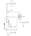
- the configuration shown in Fig. 5 can be assumed.
- power is supplied to an external device 913 (an electronic control device provided outside) by a main power supply 910 and an auxiliary power supply 911.
- the external device 913 turns on the relay 915 and when the user turns off the operation switch 916, the external device 913 relays. Is turned off.
- the power supply to the external device 913 can be maintained if there is no problem in the auxiliary power source 911 and its path. Therefore, the external device 913 can continue the same operation after the power failure as before the failure. For example, when the relay 915 was controlled to be in the ON state immediately before the power failure, the relay 915 can be continuously maintained in the ON state even after the failure, and conversely, immediately before the power failure. If the relay 915 was kept in the OFF state until then, it becomes possible to keep the relay 915 in the OFF state even after the failure.
- the capacity of the auxiliary power source 911 is equal to the load after the failure. Not only the capacity required to drive the external device 913 but also the capacity required to drive the external device 913 after the failure. Therefore, the size of the auxiliary power supply 911 is likely to increase.
- a vehicle power supply control device which is an example of the present disclosure, A power supply control device for a vehicle, comprising: a relay that switches between supply and cutoff of electric power from a main power supply to a vehicle load; and a control unit that controls the relay, The control unit, when the power supply from the main power supply is in a normal state, when the command for instructing the control content of the relay is output from the external device that operates based on the power from the main power supply, The relay is controlled based on the corresponding signal, and when the power supply from the main power source changes from the normal state to the failure state, the relay is independently controlled regardless of the corresponding signal.
- a vehicle power supply device which is an example of the present disclosure,
- the above vehicle power supply control device At least an auxiliary power supply that supplies power to the vehicle load when the power supply from the main power supply changes from a normal state to a failure state, Have.
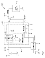
- FIG. 1 is a circuit diagram schematically showing a vehicle system including a vehicle power supply control device according to a first embodiment.
- FIG. 2 is a schematic view of the power supply state of the main power supply, the voltage information of the main power supply, the command from the external device (the external device command), and the state of the signal for controlling the relay (relay drive signal) in the vehicle system of FIGS. It is a timing chart which shows typically.
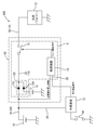
- FIG. 3 is a circuit diagram schematically showing a vehicle system including the vehicle power supply control device according to the second embodiment.
- FIG. 4 is a timing chart schematically showing the power supply state of the main power supply, the voltage information of the main power supply, the command from the external device (the external device command), and the load current in the vehicle system of FIGS.
- FIG. 2 is a schematic view of the power supply state of the main power supply, the voltage information of the main power supply, the command from the external device (the external device command), and the state of the signal for controlling the relay (relay drive signal) in the vehicle system
- FIG. 5 is a circuit diagram schematically showing a vehicle system of a comparative example.
- FIG. 6 is a circuit diagram schematically showing a vehicle system including the vehicle power supply control device according to the third embodiment.
- FIG. 7 is a circuit diagram schematically showing a vehicle system including the vehicle power supply control device according to the fourth embodiment.
- the vehicle power supply control device exemplified in the present disclosure may include a relay that switches between supply and cutoff of electric power from the main power supply to the vehicle load, and a control unit that controls the relay.
- the control unit When the power supply from the main power supply is in a normal state, the control unit outputs the corresponding signal corresponding to the command when the external device that operates based on the power from the main power supply outputs a command to control the content of the relay.
- the relay can be controlled independently of the corresponding signal when the power supply from the main power supply changes from the normal state to the failure state. With this configuration, even when the power supply from the main power source changes to the failure state and the external device does not operate, the control unit continues to control the relay before the change. be able to.
- the vehicle power supply control device exemplified in the present disclosure further includes an auxiliary power supply that supplies power to the vehicle load at least when the power supply from the main power supply changes from a normal state to a failure state, and the control unit includes an auxiliary power source. It may operate based on the power from the power supply.
- the control unit can be operated by the power from the auxiliary power supply. Further, since the state of the relay can be continued without supplying power from the auxiliary power source to the external device after changing to the failure state, the size of the auxiliary power source can be easily suppressed.
- the control unit when the control unit changes from the normal state to the failure state, the control unit can maintain the control immediately before the change from the normal state to the failure state. If configured in this way, the control unit maintains control immediately before the change from the normal state to the failure state, so that even if the command from the external device is interrupted due to the change to the failure state, the control unit is interrupted. Control according to the immediately preceding command can be continued to the relay.
- the control unit when the main power supply is in a normal state, the control unit turns on the relay when the corresponding signal is the first corresponding signal, and the corresponding signal is the second corresponding signal. If so, the relay may be turned off. Further, when the corresponding signal immediately before the change from the normal state to the failure state is the first corresponding signal, the relay is maintained in the ON state when changing to the failure state, and changes from the normal state to the failure state. When the immediately preceding corresponding signal is the second corresponding signal, the relay may be maintained in the OFF state after changing to the failure state.
- the vehicle power supply control device exemplified in the present disclosure allows the supply of current from the main power supply to the vehicle load side and prevents the flow of current from the auxiliary power supply side to the main power supply side, and the auxiliary power supply.
- a second element that allows the supply of current to the vehicle load side and prevents the flow of current from the main power supply side to the auxiliary power supply may be included.
- the corresponding signal may be output when the external device receives power from the main power supply. If configured in this way, after more surely suppressing or preventing the flow of current from the auxiliary power supply to the external device when a failure condition occurs, after the operation of the external device due to the failure condition is stopped. Also, the control of the relay before the failure can be continued.
- the vehicle load targeted by the vehicle power supply control device exemplified in the present disclosure may include a lamp that is turned on when the relay is in the on state and turned off when the relay is in the off state.
- the control unit may be operated so that a corresponding signal instructing the control content of the lamp is input from an external device.
- the vehicle load targeted by the vehicle power supply control device exemplified in the present disclosure may include a wiper that is driven when the relay is in the on state and stops when the relay is in the off state.
- the control unit may be operated so that a corresponding signal instructing the control content of the wiper is input from an external device.
- a vehicle power supply device exemplified in the present disclosure includes the vehicle power supply control device described above, and an auxiliary power supply that supplies power to a vehicle load at least when power supply from a main power supply changes from a normal state to a failure state. Can have With this configuration, it is possible to obtain the same effects as the above-described vehicle power supply control device.
- FIG. 1 illustrates a vehicle power supply system 100 including a vehicle power supply control device 1 (hereinafter, also referred to as a control device 1) according to a first embodiment.
- a vehicle power supply control device 1 hereinafter, also referred to as a control device 1
- the vehicle power supply system 100 shown in FIG. 1 includes a main power supply 10 for supplying electric power to a load 12, which is a vehicle load, and at least when power supply from the main power supply 10 changes from a normal state to a failure state.
- An auxiliary power supply 11 serving as a power supply for supplying power to the load 12, a reference voltage power supply 17, and a power path 19 serving as a path for supplying power based on the main power supply 10 to the load are provided.
- the vehicle power supply system 100 is provided on the control device 1, the external device 13 that operates based on the power from the main power supply 10, the power path 19, and supplies the power from the main power supply 10 to the load 12. And a relay 15 for switching the interruption.
- the vehicle power supply system 100 is configured as a power supply system that supplies power to the load 12 using the main power supply 10 or the auxiliary power supply 11 as a power supply source.
- the main power supply side conductive path 31 In the vehicle power supply system 100, when the power supply from the main power supply 10 is in a normal state, a voltage similar to the output voltage (terminal voltage) of the main power supply 10 is applied to the main power supply side conductive path 31. Therefore, in the above normal state, power can be supplied from the main power source 10 to the load 12 via the power path 19.
- “when the power supply from the main power source 10 is in a normal state” specifically means a predetermined conductive path electrically connected to the main power source 10 (in the following description, the main power source side conductive path 31).
- the voltage of () is the case where it falls below a predetermined value.
- This predetermined value can be, for example, a value greater than 0 and significantly lower than the output voltage (terminal voltage) when the main power supply 10 is in a fully charged state.
- the main power supply 10 is configured as a known vehicle battery such as a lead battery.
- the main power source 10 has a high-potential-side terminal electrically connected to the main power source side conductive path 31 and applies a predetermined output voltage to the main power source side conductive path 31.
- the output voltage of the main power supply 10 here means the potential difference between the terminal on the high potential side of the main power supply 10 and the ground.
- a first element (specifically, the source of the first switch element 33) described later is connected to the main power supply side conductive path 31, and in the configuration of FIG. 1, the source of the first power supply 10 is connected to the source of the first switch element 33. A voltage similar to the output voltage is applied.
- the auxiliary power supply 11 and the reference voltage power supply 17 are configured by a known power storage means such as an electric double layer capacitor (EDLC).
- the auxiliary power supply 11 has a function of supplying power to the load 12 when the power supply from the main power supply 10 changes from a normal state to a failure state.
- One terminal (high-potential-side terminal) of the auxiliary power supply 11 is electrically connected to the second element (specifically, the source of the second switch element 34).
- the other terminal (low potential side terminal) of the auxiliary power supply 11 is electrically connected to the ground and is kept at a predetermined potential (for example, 0 V).
- One terminal (high-potential side terminal) of the reference voltage power supply 17 is electrically connected to the comparator 39.
- the other terminal (low potential side terminal) of the reference voltage power supply 17 is electrically connected to the ground and is maintained at a predetermined potential (for example, 0 V).
- a voltage similar to the output voltage of the auxiliary power supply 11 is applied to the source of the second switch element 34.
- the output voltage of the auxiliary power supply 11 here means the potential difference between the high potential side terminal of the auxiliary power supply 11 and the ground.
- a voltage approximately equal to the output voltage of the reference voltage power supply 17 is applied to the comparator 39.
- the output voltage of the reference voltage power supply 17 here means the potential difference between the high potential side terminal of the reference voltage power supply 17 and the ground.
- the magnitude of the output voltage of the reference voltage power supply 17 is set to, for example, a predetermined value used to determine whether the power supply from the main power supply 10 is in a normal state or a failure state.
- the electric power path 19 includes a main power supply side conductive path 31, an intermediate conductive path 32, and a load side conductive path 30.
- the main power supply side conductive path 31 is a conductive path between the main power supply 10 and the first switch element 33, and is a conductive path to which the output voltage of the main power supply 10 is applied.
- the intermediate conductive path 32 is a conductive path between the first switch element 33 and the relay 15, and is a conductive path to which a voltage based on the output voltage of the main power supply 10 or a voltage based on the output voltage of the auxiliary power supply 11 is applied. ..
- the load-side conductive path 30 is a conductive path between the relay 15 and the load 12, and is a conductive path through which the load current flows when the relay 15 is in the ON state.
- the load 12 is configured as one type or two or more types of known on-vehicle electrical components, and specifically, an electrical component that is desired to be supplied with power even when the main power source 10 fails. Suitable examples of the load 12 include, for example, a headlight, a wiper, a meter lamp, and the like, and may be an ECU (Electronic Control Unit) or an actuator in a shift-by-wire system.
- the load 12 operates based on the power supplied from the main power supply 10 when the main power supply 10 is in a normal state, and operates based on the power supplied from the auxiliary power supply 11 when the main power supply 10 is in a failed state.
- the external device 13 is a vehicle-mounted electronic control device including, for example, a microcomputer, and is configured as a so-called ECU (Electronic Control Unit).
- the external device 13 is a device that receives power from the main power supply 10.
- the external device 13 includes a main power source side conductive path 31 (a path between the first switch element 33 (first element) and the main power source 10 in the power path 19) and a supply path 36 (main power source side conductive path). Power is supplied from the main power supply 10 via a conductive path connected to the path 31.
- the external device 13 has a function of transmitting a command instructing the control content for the load 12 to the control circuit 14 which is a control unit.
- the first command is output when the switch 16 described later is in the on state (closed state), and the second command is output when the switch 16 is in the off state (open state).
- the first command and the second command transmitted from the external device 13 are collectively referred to as an external device command (or simply command).
- the switch 16 is provided, for example, near the driver's seat of the vehicle so that the driver sitting in the driver's seat can freely operate it.
- the switch 16 may be a switch for switching the headlight between a lighting state and a non-lighting state, or may be a switch for switching the wiper between an operating state and a stopped state. Alternatively, it may be a switch for switching the meter lamp between a lighting state and a non-lighting state.
- an external device 13 receives an ON signal (indicating that the switch 16 is in an ON state). Signal) is input.
- the external device 13 transmits a first command for instructing the power supply to the load 12 to the control circuit 14 while the ON signal is input.
- the first command is, for example, a signal (H level signal) having a voltage equal to or higher than a predetermined threshold.
- an off signal (a signal indicating that the switch 16 is in the off state) is input to the external device 13. While such an OFF signal is being input, the external device 13 transmits a second command for instructing the control circuit 14 to stop the power supply to the load 12.
- the second command is, for example, a signal having a voltage lower than a predetermined threshold (L level signal).
- the control device 1 is a device that controls the power supply from the auxiliary power supply 11 at least when it is in a failed state, and mainly includes a control circuit 14, a signal transmission unit 20, and an OR circuit unit 35.
- the control circuit 14 is configured as, for example, a microcomputer or an IC having a logic circuit, and has a configuration capable of controlling the load 12 according to a command from the external device 13. Specifically, the control circuit 14 controls the relay 15. The control circuit 14 consumes less power than the external device 13, and is configured to operate based on the power supplied from the auxiliary power supply 11 via the supply path 38. The control circuit 14 is electrically connected to the intermediate conductive path 32 so that power is supplied from the auxiliary power supply 11 even when the power supply from the main power supply 10 is in a failed state. Further, a voltage signal indicating the voltage of the main power supply side conductive path 31 is input to the control circuit 14 as the voltage information of the main power supply 10, and the control circuit 14 controls the main power supply side conductive path 31.
- the voltage can be continuously monitored.
- the configuration in which the voltage signal indicating the voltage of the main power supply side conductive path 31 is input to the control circuit 14 may be a configuration in which the voltage of the main power supply side conductive path 31 is directly input to the control circuit 14.
- the voltage of the conductive path 31 may be divided by the voltage dividing circuit and input to the control circuit 14.
- the signal transmission unit 20 is a conductive path interposed between the external device 13 and the control circuit 14, and sends a signal according to a command (first command or second command) output from the external device 13 to the control circuit 14. It is a route for inputting.
- the signal transmission section 20 inputs the H level signal to the control circuit 14 as the first corresponding signal, and the external device 13 outputs the first corresponding signal.
- two commands L level signal
- the L level signal is input to the control circuit 14 as the second corresponding signal.
- the OR circuit unit 35 includes a first switch element 33 interposed between the main power source 10 and the relay 15 in the power path 19, a second switch element 34 interposed between the intermediate conductive path 32 and the auxiliary power source 11, It has a comparator 39 and an inverting section 37.
- the first switch element 33 corresponds to an example of the first element.
- the second switch element 34 corresponds to an example of the second element.
- a MOSFET Metal Oxide Semiconductor Field Effect Transistor
- Each of the first switch element 33 and the second switch element 34 has a configuration in which parasitic diodes 33A and 34A, which are parasitic components, are provided. Specifically, in each of the first switch element 33 and the second switch element 34, the cathode of each parasitic diode 33A, 34A is electrically connected to the drain side, and the anode is electrically connected to the source side.
- the voltage of the main power supply side conductive path 31 and the output voltage of the reference voltage power supply 17 are applied to the comparator 39.
- the comparator 39 outputs a high level voltage when the voltage of the main power supply 10 is equal to or higher than the output voltage of the reference voltage power supply 17 (that is, equal to or higher than a predetermined value), and the voltage of the main power supply 10 is output from the reference voltage power supply 17.
- a low level voltage smaller than the high level voltage is output.
- the comparator 39 is configured to output a voltage toward the gates of the first switch element 33 and the second switch element 34. Specifically, the voltage of the comparator 39 is directly applied to the gate of the first switch element 33, and the voltage is applied to the gate of the second switch element 34 via the inverting section 37. There is.
- the inverting unit 37 is configured to output a low level voltage when a high level voltage is input and output a high level voltage when a low level voltage is input. With this configuration, when the voltage of the main power supply 10 is equal to or higher than the output voltage of the reference voltage power supply 17 (that is, equal to or higher than a predetermined value), the OR circuit unit 35 applies a high level voltage to the gate of the first switch element 33 to make the first voltage.
- the 1-switch element 33 is turned on, and the low-level voltage is applied to the gate of the second switch element 34 to turn off the second switch element 34.
- the second switch element 34 allows the current supply from the auxiliary power supply 11 to the load 12 side and prevents the current flow from the main power supply 10 side to the auxiliary power supply 11.
- the OR circuit unit 35 applies a low level voltage to the gate of the first switch element 33 to perform the first switch.
- the element 33 is turned off, and a high level voltage is applied to the gate of the second switch element 34 to turn on the second switch element 34.
- the first switch element 33 permits the supply of current from the main power supply 10 to the load 12 side, and prevents the flow of current from the auxiliary power supply 11 side to the main power supply 10 side.
- the OR circuit unit 35 prevents the current from flowing from the intermediate conductive path 32 side to the main power source 10 side when the power supply based on the main power source 10 changes from the normal state to the failure state. ), and the current from the auxiliary power supply 11 is made to flow to the intermediate conductive path 32 via the second switch element 34 (second element).
- the drain of the first switch element 33 is electrically connected to the intermediate conductive path 32, and the source thereof is electrically connected to the main power supply side conductive path 31. Therefore, the first switch element 33 allows a bidirectional current flow between the main power supply side conductive path 31 and the intermediate conductive path 32 by applying a high level voltage to the gate.
- the first switch element 33 allows a current to flow from the main power supply side conductive path 31 to the intermediate power supply path 32 by applying a low level voltage to the gate, and the intermediate power conductive path 32 to the main power supply side conductive path 31. Cut off the flow of current.
- the cathode of the second switch element 34 is electrically connected to the intermediate conductive path 32, and the anode is electrically connected to the high potential side terminal of the auxiliary power supply 11. Therefore, the second switch element 34 allows a bidirectional current flow between the auxiliary power source 11 side and the intermediate conductive path 32 by applying a high level voltage to the gate.
- the second switch element 34 allows a current to flow from the auxiliary power source 11 side to the intermediate conductive path 32 by applying a low level voltage to the gate, and allows a current to flow from the intermediate conductive path 32 to the auxiliary power source 11 side. Shut off.
- the auxiliary power supply 11 may be configured so that it can be charged based on the electric power supplied from the main power supply 10.
- the auxiliary power supply 11 is not limited to this example, and may be configured to be charged by a charging circuit (not shown).
- the charging circuit is configured as, for example, a known voltage conversion circuit such as a DCDC converter, and can apply a predetermined voltage to the high potential side terminal of the auxiliary power supply 11 using the voltage of the main power supply side conductive path 31 as an input voltage. Has become.
- the control circuit 14 may control the charging circuit, or a device different from the control circuit 14 may control the charging circuit.
- the charging circuit may have a function as a discharging circuit, and a circuit capable of discharging the auxiliary power supply 11 may be provided separately from the charging circuit.
- a state in which the voltage of the main power source side conductive path 31 is equal to or higher than a predetermined value is a normal state (a state in which the power supply from the main power source 10 is normal). Further, a state in which the voltage of the main power source side conductive path 31 is less than a predetermined value is referred to as a failure state (a state in which power supply from the main power source 10 has failed).
- the predetermined value here is a fixed value that is greater than 0 and significantly lower than the output voltage of the main power supply 10 when fully charged.
- the comparator 39 Since the voltage of the main power supply side conductive path 31 is equal to or higher than a predetermined value, the comparator 39 outputs a high level voltage. As a result, a high level voltage is applied to the gate of the first switch element 33 to turn on the first switch element 33, and a low level voltage is applied to the gate of the second switch element 34 to cause the second switch element 34 to operate. Turns off. Therefore, the first switch element 33 allows the bidirectional current flow between the main power source side conductive path 31 and the intermediate conductive path 32, and the second switch element 34 allows the current from the auxiliary power source 11 side to the intermediate conductive path 32. Is allowed, and the flow of current from the intermediate conductive path 32 to the auxiliary power supply 11 side is blocked.
- Information on the voltage of the main power source side conductive path 31 (voltage information of the main power source 10) is input to the control circuit 14, and the control circuit 14 determines that the voltage of the main power source side conductive path 31 is the predetermined value. If the value is equal to or more than the value, the relay 15 is controlled according to the voltage applied to the signal transmission unit 20. For example, when the voltage applied to the signal transmission unit 20 in the normal state is L level (that is, when the L level signal (second command) is input from the external device 13 to the control circuit 14), the control is performed. The second corresponding signal is input to the circuit 14 to maintain the relay 15 in the off state.
- the control circuit 14 outputs an OFF signal (L level signal) as a relay drive signal for the relay 15, and the relay 15 is OFF while the OFF signal (L level signal) is being given from the control circuit 14. It becomes a state.
- the control circuit 14 When the voltage applied to the signal transmission unit 20 is at the H level (that is, when the H level signal (first command) is input from the external device 13 to the control circuit 14), the control circuit 14 has the first signal. The corresponding signal is input and the relay 15 is maintained in the ON state.
- the control circuit 14 outputs an ON signal (H level signal) as a relay drive signal to the relay 15, and the relay 15 is ON while the ON signal (H level signal) is given from the control circuit 14. It becomes a state.
- the control circuit 14 when the power supply from the main power supply 10 is in a normal state, the control circuit 14 outputs a command when the external device 13 that operates based on the power from the main power supply 10 outputs a command to instruct the control content of the relay 15.
- the relay 15 is controlled based on the corresponding signal corresponding to.
- the case where the main power supply 10 changes from the normal state to the failed state is, that is, the case where the voltage of the main power supply side conductive path 31 changes from the state of being equal to or higher than the predetermined value to the state of being lower than the predetermined value.
- the comparator 39 When the voltage of the main power supply side conductive path 31 becomes lower than a predetermined value, the comparator 39 outputs a low level voltage. As a result, a low level voltage is applied to the gate of the first switch element 33 to turn off the first switch element 33, and a high level voltage is applied to the gate of the second switch element 34 to turn off the second switch element 34. It turns on. For this reason, the first switch element 33 allows the current to flow from the main power supply side conductive path 31 to the intermediate power supply path 32, and shuts off the current from the intermediate conductive path 32 to the main power supply side conductive path 31. Become. Then, the second switch element 34 allows a bidirectional current flow between the auxiliary power source 11 side and the intermediate conductive path 32.
- the voltage applied to the external device 13 via the supply path 36 decreases, so that the operation of the external device 13 is more likely to stop, and the supply path 36 increases.
- the voltage of 1 is lower than the drivable voltage of the external device 13
- the operation of the external device 13 is stopped. In this case, the command from the external device 13 may be unintentionally interrupted or changed. Therefore, in this configuration, the following measures are taken.
- the control circuit 14 monitors the voltage of the main power supply side conductive path 31, and when the power supply from the main power supply 10 changes from the normal state to the failure state (the voltage of the main power source side conductive path 31 is equal to or more than a predetermined value). From the normal power supply 11 to the predetermined value), it operates based on the power from the auxiliary power supply 11 and is given through the signal transmission unit 20 immediately before the change from the normal state to the failure state (that is, the change). Control of the instruction specified by the corresponding signal that has been input until immediately before is continued for the relay 15. That is, the control circuit 14 maintains the control immediately before the change from the normal state to the failed state when the normal state changes to the failed state.
- “immediately before changing from the normal state to the defective state” may be a minute time before the time when the voltage of the main power supply side conductive path 31 changes from the predetermined value or more to the less than the predetermined value. Alternatively, it may be at the time of change.
- the corresponding signal input via the signal transmission unit 20 until just before the power supply from the main power supply 10 changes from the normal state to the failure state is the first corresponding signal (H Level signal), that is, when the relay 15 is in the ON state immediately before the change to the failure state, the relay 15 is maintained in the ON state after the change to the failure state. That is, the relay drive signal for the relay 15 is maintained at the H level signal (ON signal) even after the failure state.
- H Level signal the first corresponding signal
- the control circuit 14 independently controls the relay 15 regardless of the corresponding signal when the power supply from the main power source 10 changes from the normal state to the failed state. In this way, the control of the relay 15 may be continued for a certain period after the failure state is changed, or may be continued until the electric power from the auxiliary power supply 11 is insufficient.
- FIG. 1 illustrates a case where the load 12 is a lamp (for example, a headlight or a lamp for a meter) as a typical example.
- the first command output from the external device 13 is a command to turn on the lamp
- the second command is a command to turn off the lamp.
- the control circuit 14 continuously puts the power path 19 into the conductive state even after the change to the failure state.
- the relay 15 can be controlled to continue lighting the lamp.
- the command from the external device 13 immediately before changing to the failure state is the second command
- the control circuit 14 continues to make the power path 19 non-conductive even after changing to the failure state.
- the relay 15 can be controlled to continue turning off the lamp.
- the control device 1 exemplified in the present disclosure includes a relay 15 that switches between supply and cutoff of electric power from the main power supply 10 to the load 12, and a control circuit 14 that controls the relay 15.
- the control circuit 14 When the power supply from the main power source 10 is in a normal state, the control circuit 14 outputs the command when the external device 13 that operates based on the power from the main power source 10 outputs a command to instruct the control content of the relay 15.
- the relay 15 is controlled based on the corresponding signal, and when the power supply from the main power source 10 changes from the normal state to the failure state, the relay 15 is independently controlled regardless of the corresponding signal. With such a configuration, even when the power supply from the main power supply 10 changes to a failure state and the external device 13 does not operate, the control circuit 14 controls the relay 15 before the change. Control can continue.
- the vehicle power supply device 50 including the control device 1 and the auxiliary power supply 11 that supplies power to the load 12 when the power supply from the main power supply 10 changes from the normal state to the failed state is The same effect as can be obtained.
- the control device 1 further includes an auxiliary power supply 11 that supplies power to the load 12 when at least the power supply from the main power supply 10 changes from a normal state to a failure state, and the control circuit 14 supplies the power from the auxiliary power supply 11 to the load. Work based on. With this configuration, if configured in this way, the control circuit 14 can be operated by the power from the auxiliary power source 11 when the power supply from the main power source 10 changes to a failure state. it can. Further, since the state of the relay 15 can be continued without supplying power from the auxiliary power source 11 to the external device 13 after changing to the failure state, the size of the auxiliary power source 11 can be easily suppressed. ..
- the control circuit 14 maintains the control immediately before the change from the normal state to the failure state when the normal state changes to the failure state. With such a configuration, the control circuit 14 maintains the control immediately before the change from the normal state to the failure state, and thus even if the command from the external device 13 is interrupted due to the change to the failure state. The control according to the command immediately before the interruption can be continued to the relay 15.
- the control circuit 14 When the main power supply 10 is in a normal state, the control circuit 14 turns on the relay 15 when the corresponding signal is the first corresponding signal, and turns off the relay 15 when the corresponding signal is the second corresponding signal. And Further, when the normal state changes to the failure state, when the corresponding signal immediately before the normal state changes to the failure state is the first corresponding signal, the relay 15 is turned on when the failure state changes. If the corresponding signal immediately before the change from the normal state to the failed state is the second corresponding signal, the relay 15 is maintained in the off state after the change to the failed state. With such a configuration, even if the first command or the second command from the external device 13 before the failure is no longer maintained due to the change from the normal state to the failed state, the relay 15 is turned on/off. You can surely continue in the same condition as before the fall. Moreover, on the control circuit 14 side, it suffices that the control circuit 14 can take over which of the first corresponding signal and the second corresponding signal was input before the failure after the failure. Will be easier to
- the control device 1 allows the supply of current from the main power supply 10 to the load 12 and prevents the flow of current from the auxiliary power supply 11 side to the main power supply 10 side, and the auxiliary power supply 33.
- the second switch element 34 (second element) that allows the supply of the current from the power supply 11 to the load 12 side and prevents the current from flowing from the main power supply 10 side to the auxiliary power supply 11 is included.
- the corresponding signal is output when the external device 13 receives power from the main power supply 10.
- the load 12 targeted by the control device 1 includes a lamp that is turned on when the relay 15 is in the on state and turned off when the relay 15 is in the off state.
- the control circuit 14 operates so that a corresponding signal indicating the control content of the lamp is input from the external device 13.
- the load 12 is a headlight
- the operation of the headlight immediately before the main power supply 10 fails can be reliably continued, so that the main power supply 10 is in a failure state in a dark environment, for example. Even in the case where the vehicle is turned on, the visibility in front of the vehicle can be secured.
- the load 12 is a meter lamp
- the operation of the meter lamp immediately before the main power source 10 fails can be reliably continued, so that the main power source 10 fails in a dark environment. Even if it becomes, the visibility of the meter can be secured.
- the vehicle power supply system 200 including the vehicle power supply device 51 including the vehicle power supply control device 2 (hereinafter also referred to as “control device 2”) according to the second embodiment has The present embodiment is different from the first embodiment in that a relay 15 is provided, and other configurations are the same as those in the first embodiment. Therefore, in the vehicle power supply control device 2, the vehicle power supply device 51, and the vehicle power supply system 200 according to the second embodiment, the same reference numerals as those in the first embodiment are attached to the same components as those in the first embodiment. Detailed description is omitted.
- the control device 2 and the vehicle power supply device 51 of the second embodiment include all the functions of the control device 1 and the vehicle power supply device 50 of the first embodiment, and can perform all the control described above in the description of the first embodiment. ..
- the vehicle power supply device 51 including the control device 2 according to the second embodiment includes the control device 2 including the control circuit 14 and the relay 15, and the auxiliary power supply 11.
- the control circuit 14, the relay 15, and the OR circuit unit 35 are configured as an integrated unit.
- the control circuit 14, the relay 15, and the OR circuit unit 35 are mounted on the same substrate. Well, they may be housed in the same case.
- the control circuit 14 outputs an L level (low level) relay drive signal to the relay 15 to control the relay 15 so as to bring the power path 19 into a non-conductive state. Therefore, electric power is not supplied from the main power source 10 to the load 12, and the load current does not flow toward the load 12.
- the external device 13 is supplied with electric power from the main power source 10, and the external device 13 transmits to the control circuit 14 the first command for instructing the power supply to the load 12.
- the voltage of the main power supply side conductive path 31 (that is, the voltage information of the main power supply 10) is also input to the control circuit 14.
- the control circuit 14 outputs an H level (high level) relay drive signal to the relay 15 so as to bring the electric power path 19 into a conductive state, and controls the relay 15 (see FIG. 4). Therefore, power is supplied from the main power source 10 to the load 12, and a load current flows toward the load 12.
- the control circuit 14 monitors the voltage of the main power supply side conductive path 31, and when the power supply from the main power supply 10 changes from the normal state to the failure state (the voltage of the main power source side conductive path 31 is equal to or more than a predetermined value). From the normal state to the failure state, the operation is performed based on the electric power from the auxiliary power supply 11 and the instruction (that is, the change that has been given through the signal transmission unit 20 immediately before the state is changed from the normal state to the failure state). Control of the instruction specified by the corresponding signal that has been input until immediately before is continued for the relay 15. For example, as shown in FIG.
- Such a control device 2 can also achieve the same effect as the control device 1. Further, the vehicle power supply device 51 having the control device 2 and the auxiliary power supply 11 that supplies power to the load 12 when the power supply from the main power supply 10 changes from the normal state to the failed state has the same effect. Can play.
- control circuit 14, the relay 15, the OR circuit section 35, etc. are configured as an integrated unit, it becomes easy to manage these as one unit, and it is easy to make the device configuration compact. In addition, it is easy to omit parts such as wiring to the relay 15 and connectors, and it is easy to reduce costs.
- the load targeted by the control device 2 may include a lamp as illustrated in the first embodiment, and when the relay 15 is in the ON state instead of the lamp or in combination with the lamp.
- a wiper that is driven and stops when the relay 15 is off may be included (see FIG. 3 ).
- the control circuit 14 may be operated so that a corresponding signal indicating the control content of the wiper is input from the external device 13. For example, the control circuit 14 controls the relay 15 to continuously maintain the relay 15 in the conductive state when the command from the external device 13 immediately before the change to the failure state is the first command to operate the wiper.
- the relay 15 is continuously maintained in the non-conductive state.
- the wiper may be stopped continuously by controlling 15.
- the vehicle power supply system 300 including the vehicle power supply device 52 including the vehicle power supply control device 3 (hereinafter, also referred to as “control device 3”) according to the third embodiment is, as shown in FIG.
- the first diode 133 is used as the first element
- the second diode 134 is used as the second element
- the other configurations are the same as those in the first embodiment. Therefore, in the third embodiment, the same components as those in the first embodiment are designated by the same reference numerals and detailed description thereof will be omitted.
- the OR circuit unit 135 has a first diode 133 interposed between the main power supply 10 and the relay 15 in the power path 19, and a second diode 134 interposed between the intermediate conductive path 32 and the auxiliary power supply 11.
- the first diode 133 corresponds to an example of the first element.
- the second diode 134 corresponds to an example of the second element.
- the OR circuit unit 135 prevents the current from flowing from the intermediate conductive path 32 side to the main power source 10 side when the power supply based on the main power source 10 changes from the normal state to the failure state.
- the first diode 133 (first element).
- the current is supplied from the auxiliary power supply 11 to the intermediate conductive path 32 via the second diode 134 (second element).
- the cathode of the first diode 133 is electrically connected to the intermediate conductive path 32, and the anode thereof is electrically connected to the main power supply side conductive path 31.
- the first diode 133 allows the current to flow from the main power supply side conductive path 31 to the intermediate power supply path 32, and blocks the current flow from the intermediate conductive path 32 to the main power supply side conductive path 31. That is, the first diode 133 permits the supply of current from the main power supply 10 to the load 12 side and prevents the flow of current from the auxiliary power supply 11 side to the main power supply 10 side.
- the cathode of the second diode 134 is electrically connected to the intermediate conductive path 32, and the anode thereof is electrically connected to the high potential side terminal of the auxiliary power supply 11.
- the second diode 134 allows the current to flow from the auxiliary power source 11 to the intermediate conductive path 32, and blocks the current from the intermediate conductive path 32 to the auxiliary power source 11. That is, the second diode 134 allows the current supply from the auxiliary power supply 11 to the load 12 side and prevents the current flow from the main power supply 10 side to the auxiliary power supply 11.
- a state in which the voltage of the main power source side conductive path 31 is equal to or higher than a predetermined value is a normal state (a state in which the power supply from the main power source 10 is normal). Further, a state in which the voltage of the main power source side conductive path 31 is less than a predetermined value is referred to as a failure state (a state in which the power supply from the main power source 10 has failed).
- the predetermined value here is a fixed value that is greater than 0 and significantly lower than the output voltage of the main power supply 10 when fully charged.
- Information on the voltage of the main power source side conductive path 31 (voltage information of the main power source 10) is input to the control circuit 14, and the control circuit 14 determines that the voltage of the main power source side conductive path 31 is the predetermined value. If the value is equal to or more than the value, the relay 15 is controlled according to the voltage applied to the signal transmission unit 20. For example, when the voltage applied to the signal transmission unit 20 in the normal state is L level (that is, when the L level signal is input from the external device 13 to the control circuit 14), the relay 15 is turned off. maintain. Specifically, the control circuit 14 outputs an OFF signal (L level signal) as a relay drive signal for the relay 15, and the relay 15 is OFF while the OFF signal (L level signal) is being given from the control circuit 14.
- L level signal an OFF signal
- the relay 15 When the voltage applied to the signal transmission unit 20 is at the H level (that is, when the H level signal is input from the external device 13 to the control circuit 14), the relay 15 is maintained in the ON state. Specifically, the control circuit 14 outputs an ON signal (H level signal) as a relay drive signal to the relay 15, and the relay 15 is ON while the ON signal (H level signal) is given from the control circuit 14. It becomes a state.
- the case where the main power supply 10 changes from the normal state to the failed state is, that is, the case where the voltage of the main power supply side conductive path 31 changes from the state of being equal to or higher than the predetermined value to the state of being lower than the predetermined value.
- the voltage applied to the external device 13 via the supply path 36 decreases, so that the operation of the external device 13 is more likely to stop and the supply path 36 is increased.
- the voltage of 1 is lower than the drivable voltage of the external device 13
- the operation of the external device 13 is stopped. In this case, the command from the external device 13 may be unintentionally interrupted or changed. Therefore, in this configuration, the following measures are taken.
- the control circuit 14 monitors the voltage of the main power supply side conductive path 31, and when the power supply from the main power supply 10 changes from the normal state to the failure state (the voltage of the main power source side conductive path 31 is equal to or more than a predetermined value). From the normal state to the failure state, the operation is performed based on the electric power from the auxiliary power supply 11 and the instruction (that is, the change that has been given through the signal transmission unit 20 immediately before the state is changed from the normal state to the failure state). Control of the instruction specified by the corresponding signal that has been input until immediately before is continued for the relay 15.
- “immediately before changing from the normal state to the defective state” may be a minute time before the time when the voltage of the main power supply side conductive path 31 changes from the predetermined value or more to the less than the predetermined value. Alternatively, it may be at the time of change.
- the corresponding signal input via the signal transmission unit 20 until just before the power supply from the main power supply 10 changes from the normal state to the failure state is the first corresponding signal (H Level signal), that is, when the relay 15 is in the ON state immediately before the change to the failure state, the relay 15 is maintained in the ON state after the change to the failure state. That is, the relay drive signal for the relay 15 is maintained at the H level signal (ON signal) even after the failure state.
- H Level signal the first corresponding signal
- the corresponding signal input through the signal transmission unit 20 is the second corresponding signal (L level signal) immediately before the power supply from the main power supply 10 changes from the normal state to the failed state, That is, if the relay 15 is in the off state immediately before the failure state is changed, the relay 15 is maintained in the off state even after the failure state is changed. In this way, the control of the relay 15 may be continued for a certain period after the failure state is changed, or may be continued until the electric power from the auxiliary power supply 11 is insufficient.
- the control device 3 exemplified in the present disclosure includes a relay 15 that switches between supply and cutoff of electric power from the main power supply 10 to the load 12, and a control circuit 14 that controls the relay 15.
- the control circuit 14 When the power supply from the main power supply 10 is in a normal state, the control circuit 14 outputs the command when the external device 13 that operates based on the power from the main power supply 10 outputs a command to instruct the control content of the relay 15.
- the relay 15 is controlled based on the corresponding signal, and when the power supply from the main power source 10 changes from the normal state to the failure state, the relay 15 is independently controlled regardless of the corresponding signal. With such a configuration, even when the power supply from the main power supply 10 changes to a failure state and the external device 13 does not operate, the control circuit 14 controls the relay 15 before the change. Control can continue.
- the vehicle power supply device 52 including the control device 3 and the auxiliary power supply 11 that supplies power to the load 12 when the power supply from the main power supply 10 changes from the normal state to the failed state is performed by the control device 3 The same effect as can be obtained.
- the control device 3 further includes an auxiliary power supply 11 that supplies power to the load 12 when at least the power supply from the main power supply 10 changes from a normal state to a failure state, and the control circuit 14 supplies the power from the auxiliary power supply 11 to the load. Work based on. With such a configuration, when the power supply from the main power supply 10 changes to a failure state, the control circuit 14 can be operated by the power from the auxiliary power supply 11. Further, since the state of the relay 15 can be continued without supplying power from the auxiliary power source 11 to the external device 13 after changing to the failure state, the size of the auxiliary power source 11 can be easily suppressed. ..
- the control circuit 14 maintains the control immediately before the change from the normal state to the failure state when the normal state changes to the failure state. With such a configuration, the control circuit 14 maintains the control immediately before the change from the normal state to the failure state, and thus even if the command from the external device 13 is interrupted due to the change to the failure state. The control according to the command immediately before the interruption can be continued to the relay 15.
- the control circuit 14 When the main power supply 10 is in a normal state, the control circuit 14 turns on the relay 15 when the corresponding signal is the first corresponding signal, and turns off the relay 15 when the corresponding signal is the second corresponding signal. And Further, when the normal state changes to the failure state, when the corresponding signal immediately before the normal state changes to the failure state is the first corresponding signal, the relay 15 is turned on when the failure state changes. If the corresponding signal immediately before the change from the normal state to the failed state is the second corresponding signal, the relay 15 is maintained in the off state after the change to the failed state. With such a configuration, even if the first command or the second command from the external device 13 before the failure is no longer maintained due to the change from the normal state to the failed state, the relay 15 is turned on/off. You can surely continue in the same condition as before the fall. Moreover, on the control circuit 14 side, it suffices that the control circuit 14 can take over which of the first corresponding signal and the second corresponding signal was input before the failure after the failure. Will be easier to
- the control device 3 allows the supply of current from the main power supply 10 to the load 12 and prevents the current from flowing from the auxiliary power supply 11 side to the main power supply 10 side, and the auxiliary power supply 11 and the first diode 133. From the main power supply 10 side to the current supply from the main power supply 10 side to the flow of the current to the load 12 side, and the second diode 134 (second element) is included. The corresponding signal is output when the external device 13 receives power from the main power supply 10. With such a configuration, it is possible to more reliably prevent the current from flowing from the auxiliary power supply 11 to the external device 13 in the case of the failure state, and after the operation of the external device 13 is stopped due to the failure state. Also, the control of the relay 15 before the failure can be continued.
- the load 12 targeted by the control device 3 includes a lamp that is turned on when the relay 15 is in the on state and turned off when the relay 15 is in the off state.
- the control circuit 14 operates so that a corresponding signal indicating the control content of the lamp is input from the external device 13.
- the load 12 is a headlight
- the operation of the headlight immediately before the main power supply 10 fails can be reliably continued, so that the main power supply 10 is in a failure state in a dark environment, for example. Even in the case where the vehicle is turned on, the visibility in front of the vehicle can be secured.
- the load 12 is a meter lamp
- the operation of the meter lamp immediately before the main power source 10 fails can be reliably continued, so that the main power source 10 fails in a dark environment. Even if it becomes, the visibility of the meter can be secured.
- the relay 15 controls the vehicle power supply system 400 including the vehicle power supply device 53 including the vehicle power supply control device 4 (hereinafter also referred to as “control device 4”) according to the fourth embodiment.
- the points provided in the device 4 are the same as those in the second embodiment, and other configurations are the same as those in the third embodiment. Parts having the same configurations as those in the third embodiment are designated by the same reference numerals as those in the third embodiment, and detailed description thereof will be omitted.
- the control device 4 and the vehicle power supply device 53 of the fourth embodiment include all the functions of the control device 3 and the vehicle power supply device 52 of the third embodiment, and can perform all the control described above in the description of the third embodiment. ..
- the vehicle power supply device 53 including the control device 4 according to the fourth embodiment includes the control device 2 including the control circuit 14 and the relay 15, and the auxiliary power supply 11.
- the control circuit 14, the relay 15, and the OR circuit unit 135 are configured as an integrated unit.
- the control circuit 14, the relay 15, and the OR circuit unit 135 are mounted on the same substrate. Well, they may be housed in the same case.
- Such a control device 4 can also achieve the same effect as the control device 3.
- the vehicle power supply device 53 having the control device 4 and the auxiliary power supply 11 that supplies power to the load 12 when the power supply from the main power supply 10 changes from the normal state to the failed state has the same effect. Can play.
- the lead battery is used as the main power source 10, but the present invention is not limited to this configuration, and in any of the above-described embodiments or any modification of the above-described embodiment, any other known battery than the lead battery is used. You may use the storage battery of.
- the electric double layer capacitor (EDLC) is used for the auxiliary power supply 11 and the reference voltage power supply 17 in the above-described embodiments
- the present invention is not limited to this configuration, and any of the above-described embodiments or any modification of the above-described embodiments is used.
- the auxiliary power supply 11 may use other power storage means such as a lithium ion battery, a lithium ion capacitor, and a nickel hydrogen rechargeable battery.
- the first switch element 33 and the second switch element 34 are on/off controlled using the comparator 39 and the inverting section 37, but even if these switch elements are controlled by the control circuit 14. Good.
- the control circuit 14 turns on the first switch element in the normal state, turns off the second switch element, turns off the first switch element in the failed state, and turns on the second switch element. It may be turned on.
- two DCDC converters are used instead of the first switch element 33 and the second switch element 34, and the control circuit 14 operates one DCDC converter in the normal state and stops the operation of the other DCDC converter.
- the other DCDC converter may be operated and the operation of one DCDC converter may be stopped.
- the ON control and the OFF control are illustrated as an example of the control of the relay 15, but the control is not limited to this example.
- it may be an on/off operation using a PWM signal.
- the external device 13 may output a plurality of types of information.
- the first information may be input to the control circuit 14, and the control circuit 14 outputs the first information.
- the PWM signal of the first duty may be output to the relay 15, and the relay 15 may be turned on and off at the first duty.
- the second command (second information) is output from the external device 13
- the second information may be input to the control circuit 14, and the control circuit 14 outputs the second information.
- the PWM signal of the second duty may be output to the relay 15 and the relay 15 may be turned on/off at the second duty.
- the third command (third information) is output from the external device 13
- the third information may be input to the control circuit 14, and the control circuit 14 outputs the third information.
- the PWM signal of the third duty may be output to the relay 15 and the relay 15 may be turned on/off at the third duty.
- control circuit 14 may continuously output the PWM signal of the first duty to the relay 15 even after changing to the failure state, and continue the control of turning on/off the relay 15 at the first duty. it can.
- the control circuit 14 outputs the PWM of the second duty to the relay 15 even after the change to the failure state. It is possible to continuously output the signal and continue the control of turning on/off the relay 15 at the second duty.
- the signal output from the external device 13 is input to the control circuit 14, but the present invention is not limited to this example.
- the signal transmission unit inputs the L level signal, which is the inverted H level signal, to the control circuit 14 as the first corresponding signal
- the external device When 13 outputs the second command (L level signal), the H level signal obtained by inverting the L level signal may be input to the control circuit 14 as the second corresponding signal.
- the control circuit 14 can specify the command from the external device 13.
- control circuit 14, the relay 15, the OR circuit unit 135 and the like are further configured as an integrated unit, it becomes easy to manage these as one unit, and the device configuration can be made compact. It becomes easier to plan. In addition, it is easy to omit parts such as wiring to the relay 15 and connectors, and it is easy to reduce costs.
- the load targeted by the control device 4 may include a lamp as illustrated in the first and third embodiments, and instead of the lamp or in combination with the lamp, the relay 15 is used. May include a wiper that is driven when the relay is in the on state and stopped when the relay 15 is in the off state (see FIG. 7).
- the control circuit 14 may be operated so that a corresponding signal indicating the control content of the wiper is input from the external device 13.
- the control circuit 14 controls the relay 15 so as to continuously maintain the relay 15 in the conductive state when the command from the external device 13 immediately before the change to the failed state is the first command to operate the wiper.
- the relay 15 is continuously maintained in the non-conducting state.
- the wiper may be stopped continuously by controlling 15.
- Vehicle power supply control device 10 ... Main power supply 11... Auxiliary power supply 12... Load (vehicle load) 13... External device 14... Control circuit (control unit) 15...Relay 16...Switch 17...Reference voltage power source 19...Power path 20...Signal transmission section 30...Load side conductive path 31...Main power source side conductive path 32...Intermediate conductive path 33...First switch element (first element) 33A... Parasitic diode 34... Second switch element (second element) 34A... Parasitic diodes 35, 135... OR circuit section 36... Supply path 37... Inversion section 38... Supply path 39... Comparator 50, 51, 52, 53... Vehicle power supply device 100, 200, 300, 400... Vehicle power supply system 133... First diode (first element) 134... Second diode (second element) 910... Main power supply 911... Auxiliary power supply 913... External device 915... Relay 916... Operation switch
Landscapes
- Engineering & Computer Science (AREA)
- Power Engineering (AREA)
- Mechanical Engineering (AREA)
- Transportation (AREA)
- Charge And Discharge Circuits For Batteries Or The Like (AREA)
Abstract
主電源からの電力供給が失陥状態に変化した場合であっても変化前の制御を継続し得る構成を実現する。 車両用電源制御装置(1)は、主電源(10)から負荷(12)への電力の供給及び遮断を切り替えるリレー(15)と、リレー(15)の制御を行う制御回路(14)とを備える。制御回路(14)は、主電源(10)からの電力供給が正常状態においては主電源(10)からの電力に基づいて動作する外部装置(13)からリレー(15)の制御内容を指示する指令が出力された場合に、指令に対応する対応信号に基づいてリレー(15)を制御し、主電源(10)からの電力供給が正常状態から失陥状態に変化した場合には対応信号によらず独立してリレー(15)を制御する。
Description
本開示は、車両用電源制御装置、及び車両用電源装置に関するものである。
特許文献1には、バッテリからの電力供給が絶たれても一時的に電装品の動作を可能とするバックアップ電源装置が開示されている。特許文献1で開示される装置は、バックアップ電源での不必要な動作に伴う電力消費を抑えることで車両の燃費悪化を抑制することを目的とするものとなっている。
バックアップ動作を行い得る車両用電源システムとしては、図5のような構成を想定することもできる。図5で開示される車両用電源システムは、主電源910及び補助電源911によって外部装置913(外部に設けられた電子制御装置)に対して電力が供給されるようになっており、主電源910から正常に電力が供給され得る場合には、ユーザが操作スイッチ916をオン動作させたときに外部装置913がリレー915をオン動作させ、操作スイッチ916をオフ動作させたときに外部装置913がリレーをオフ動作させるようになっている。
図5で開示されるシステムでは、主電源910又はその経路において電源失陥が生じた場合であっても、補助電源911及びその経路において支障がなければ外部装置913に対する電力供給を維持することができるため、外部装置913は電源失陥後においても失陥前と同様の動作を継続することが可能となる。例えば、電源失陥の直前までリレー915をオン状態に制御していた場合には、失陥後もリレー915を継続してオン状態で維持することが可能となり、逆に、電源失陥の直前までリレー915をオフ状態で維持していた場合には、失陥後もリレー915を継続してオフ状態で維持することが可能となる。
しかし、図5のように構成した場合、主電源910又はその経路において電源失陥が生じた後も外部装置913の駆動を維持する必要があるため、補助電源911の容量は、失陥後に負荷を駆動するために必要となる容量のみならず、失陥後に外部装置913を駆動するために必要となる容量も確保しなければならない。従って、補助電源911のサイズの大型化を招きやすい。
そこで、上述した課題の少なくとも一つを解決するために、主電源からの電力供給が失陥状態に変化した場合であっても変化前の制御を継続し得る構成を実現する装置を提案する。
本開示の一例である車両用電源制御装置は、
主電源から車両負荷への電力の供給及び遮断を切り替えるリレーと、前記リレーの制御を行う制御部と、を備えた車両用電源制御装置であって、
前記制御部は、前記主電源からの電力供給が正常状態においては前記主電源からの電力に基づいて動作する外部装置から前記リレーの制御内容を指示する指令が出力された場合に、前記指令に対応する対応信号に基づいて前記リレーを制御し、前記主電源からの電力供給が前記正常状態から失陥状態に変化した場合には前記対応信号によらず独立して前記リレーを制御する。
主電源から車両負荷への電力の供給及び遮断を切り替えるリレーと、前記リレーの制御を行う制御部と、を備えた車両用電源制御装置であって、
前記制御部は、前記主電源からの電力供給が正常状態においては前記主電源からの電力に基づいて動作する外部装置から前記リレーの制御内容を指示する指令が出力された場合に、前記指令に対応する対応信号に基づいて前記リレーを制御し、前記主電源からの電力供給が前記正常状態から失陥状態に変化した場合には前記対応信号によらず独立して前記リレーを制御する。
本開示の一例である車両用電源装置は、
上記の車両用電源制御装置と、
少なくとも前記主電源からの電力供給が正常状態から失陥状態に変化した場合に前記車両負荷へ電力を供給する補助電源と、
を有する。
上記の車両用電源制御装置と、
少なくとも前記主電源からの電力供給が正常状態から失陥状態に変化した場合に前記車両負荷へ電力を供給する補助電源と、
を有する。
本開示によれば、主電源からの電力供給が失陥状態に変化した場合であっても変化前の制御を継続し得る構成を実現することができる。
本開示で例示される車両用電源制御装置は、主電源から車両負荷への電力の供給及び遮断を切り替えるリレーと、リレーの制御を行う制御部とを備え得る。制御部は、主電源からの電力供給が正常状態においては主電源からの電力に基づいて動作する外部装置からリレーの制御内容を指示する指令が出力された場合に、指令に対応する対応信号に基づいてリレーを制御し、主電源からの電力供給が正常状態から失陥状態に変化した場合には対応信号によらず独立してリレーを制御し得る。このように構成されていれば、主電源からの電力供給が失陥状態に変化して外部装置が動作しない状態になった場合であっても制御部によって、変化前のリレーの制御を継続することができる。
本開示で例示される車両用電源制御装置において、少なくとも主電源からの電力供給が正常状態から失陥状態に変化した場合に車両負荷へ電力を供給する補助電源をさらに備え、制御部は、補助電源からの電力に基づいて動作し得る。このように構成されていれば、主電源からの電力供給が失陥状態に変化した場合に、補助電源からの電力によって制御部を動作させることができる。また、失陥状態に変化した後に補助電源から外部装置に電力を供給しなくてもリレーの状態を継続することができるため、補助電源のサイズを抑え易い構成とすることができる。
本開示で例示される車両用電源制御装置において、制御部は、正常状態から失陥状態に変化した場合において、正常状態から失陥状態に変化する直前の制御を維持し得る。このように構成されていれば、制御部は、正常状態から失陥状態に変化する直前の制御を維持するため、仮に失陥状態に変化したことによって外部装置からの指令が途絶えても、途絶える直前の指令に応じた制御をリレーに対して継続することができる。
本開示で例示される車両用電源制御装置において、制御部は、主電源が正常状態においては、対応信号が第1対応信号である場合にはリレーをオン状態とし、対応信号が第2対応信号である場合にはリレーをオフ状態としてもよい。また、正常状態から失陥状態に変化する直前の対応信号が第1対応信号の場合には、失陥状態に変化した場合にリレーをオン状態に維持し、正常状態から失陥状態に変化する直前の対応信号が第2対応信号の場合には、失陥状態に変化した後にリレーをオフ状態に維持してもよい。このように構成されていれば、正常状態から失陥状態に変化することによって失陥前の外部装置からの指令が維持されなくなったとしても、リレーのオンオフ状態を失陥前と同じ状態で確実に継続することができる。しかも、制御回路側では、失陥前に第1対応信号又は第2対応信号のいずれが入力されていたかを失陥後において引き継ぐことができる構成であれば足りるため、簡易な構成で上記効果を得易くなる。
本開示で例示される車両用電源制御装置は、主電源から車両負荷側への電流の供給を許容し、補助電源側から主電源側への電流の流れを防ぐ第1素子と、補助電源から車両負荷側への電流の供給を許容し、主電源側から補助電源への電流の流れを防ぐ第2素子と、を含んでいてもよい。そして、対応信号は、外部装置が主電源から電力供給を受けることによって出力される構成をなしていてもよい。このように構成されていれば、失陥状態となったときに補助電源から外部装置へと電流が流れ込むことをより確実に抑制又は防止しつつ、失陥状態に起因する外部装置の動作停止後にも、失陥前のリレーに対する制御を継続することができる。
本開示で例示される車両用電源制御装置が対象とする車両負荷は、リレーがオン状態である場合に点灯し、リレーがオフ状態である場合に消灯するランプを含んでいてもよい。制御部には、外部装置からランプの制御内容を指示する対応信号が入力されるように動作してもよい。このように構成されていれば、外部装置からの指令に応じてランプの制御がなされ得る構成において、失陥状態に起因して外部装置の動作が停止したとしても、変化前のランプの状態を継続することができ、このような構成を、補助電源のサイズを抑え易い構成で実現することができる。
本開示で例示される車両用電源制御装置が対象とする車両負荷は、リレーがオン状態である場合に駆動し、リレーがオフ状態である場合に停止するワイパーを含んでいてもよい。制御部には、外部装置からワイパーの制御内容を指示する対応信号が入力されるように動作してもよい。このように構成されていれば、外部装置からの指令に応じてワイパーの制御がなされ得る構成において、失陥状態に起因して外部装置の動作が停止したとしても、変化前のワイパーの状態を継続することができ、このような構成を、補助電源のサイズを抑え易い構成で実現することができる。
本開示で例示される車両用電源装置は、上記の車両用電源制御装置と、少なくとも主電源からの電力供給が正常状態から失陥状態に変化した場合に車両負荷へ電力を供給する補助電源とを有し得る。このように構成されていれば、上記の車両用電源制御装置と同様の効果を奏することができる。
以下、本発明を具体化した実施例について説明する。
<実施例1>
図1には、実施例1に係る車両用電源制御装置1(以下、制御装置1ともいう)を備えた車両用電源システム100が例示されている。
<実施例1>
図1には、実施例1に係る車両用電源制御装置1(以下、制御装置1ともいう)を備えた車両用電源システム100が例示されている。
図1で示される車両用電源システム100は、車両負荷である負荷12へ電力を供給するための主電源10と、少なくとも主電源10からの電力供給が正常状態から失陥状態に変化した場合に負荷12へ電力を供給する電源となる補助電源11と、基準電圧電源17と、主電源10に基づく電力を負荷へ供給する経路となる電力路19とを備える。更に、車両用電源システム100は、上記の制御装置1と、主電源10からの電力に基づいて動作する外部装置13と、電力路19に設けられるとともに主電源10から負荷12への電力の供給及び遮断を切り替えるリレー15とを備える。この車両用電源システム100は、主電源10又は補助電源11を電力供給源として負荷12に電力を供給する電源システムとして構成されている。
なお、以下の説明では、特に明示的な限定がない限り、「電圧」とはグラウンドとの電位差を意味する。
車両用電源システム100は、主電源10からの電力供給が正常状態のときに主電源10の出力電圧(端子電圧)と同程度の電圧が主電源側導電路31に印加されるようになっており、上記正常状態のときに主電源10から電力路19を介して負荷12に電力を供給し得る。本構成において「主電源10からの電力供給が正常状態のとき」とは、具体的には、主電源10に電気的に接続された所定導電路(以下の説明では、主電源側導電路31)の電圧が所定値以下に低下した場合をいう。この所定値は、例えば、0より大きく且つ主電源10が満充電状態のときの出力電圧(端子電圧)よりも大幅に低い値とすることができる。
主電源10は、例えば、鉛バッテリ等の公知の車載バッテリとして構成されている。主電源10は、高電位側の端子が主電源側導電路31に電気的に接続され、主電源側導電路31に対して所定の出力電圧を印加する。ここでいう主電源10の出力電圧は、主電源10の高電位側の端子とグラウンドとの電位差を意味する。主電源側導電路31には後述する第1素子(具体的には第1スイッチ素子33のソース)が接続されており、図1の構成では、第1スイッチ素子33のソースに主電源10の出力電圧と同程度の電圧が印加されるようになっている。
補助電源11、及び基準電圧電源17は、例えば、電気二重層キャパシタ(EDLC)等の公知の蓄電手段によって構成されている。補助電源11は、主電源10からの電力供給が正常状態から失陥状態に変化した場合に負荷12へ電力を供給する機能を有する。補助電源11の一方の端子(高電位側端子)は第2素子(具体的には第2スイッチ素子34のソース)に電気的に接続されている。補助電源11の他方の端子(低電位側端子)はグラウンドに電気的に接続され、所定電位(例えば0V)に保たれている。基準電圧電源17の一方の端子(高電位側端子)はコンパレータ39に電気的に接続されている。基準電圧電源17の他方の端子(低電位側端子)はグラウンドに電気的に接続され、所定電位(例えば0V)に保たれている。図1の構成では、第2スイッチ素子34のソースに補助電源11の出力電圧と同程度の電圧が印加されるようになっている。ここでいう補助電源11の出力電圧は、補助電源11の高電位側端子とグラウンドとの電位差を意味する。図1の構成では、コンパレータ39に基準電圧電源17の出力電圧と同程度の電圧が印加されるようになっている。ここでいう基準電圧電源17の出力電圧は、基準電圧電源17の高電位側端子とグラウンドとの電位差を意味する。基準電圧電源17の出力電圧の大きさは、例えば、主電源10からの電力供給が正常状態であるか失陥状態であるかを判別するために用いられる所定値に設定されている。
電力路19は、主電源側導電路31と中間導電路32と負荷側導電路30とを備える。主電源側導電路31は、主電源10と第1スイッチ素子33との間の導電路であり、主電源10の出力電圧が印加される導電路である。中間導電路32は、第1スイッチ素子33とリレー15との間の導電路であり、主電源10の出力電圧に基づく電圧又は補助電源11の出力電圧に基づく電圧が印加される導電路である。負荷側導電路30は、リレー15と負荷12との間の導電路であり、リレー15がオン状態となっているときに負荷電流が流れる導電路である。
負荷12は、1種類又は2種類以上の公知の車載用電気部品として構成され、具体的には、主電源10が失陥した場合でも電力供給が望まれる電気部品である。負荷12の好適例としては、例えば、ヘッドライト、ワイパー、メーター用ランプなどが挙げられ、シフトバイワイヤシステムにおけるECU(Electronic Control Unit)やアクチュエータ等あってもよい。負荷12は主電源10が正常状態のときには主電源10から供給される電力に基づいて動作し、主電源10が失陥状態のときには補助電源11から供給される電力に基づいて動作する。
外部装置13は、例えばマイクロコンピュータを備えた車載用電子制御装置であり、所謂ECU(Electronic Control Unit)として構成されている。外部装置13は、主電源10から電力供給を受ける装置である。具体的には、外部装置13は、主電源側導電路31(電力路19における第1スイッチ素子33(第1素子)と主電源10との間の経路)及び供給路36(主電源側導電路31に接続される導電路)を介して主電源10に基づく電力の供給を受ける。外部装置13は、負荷12に対する制御内容を指示する指令を制御部である制御回路14に送信する機能を有する。具体的には、後述するスイッチ16がオン状態(閉状態)のときに第1指令を出力し、スイッチ16がオフ状態(開状態)のときに第2指令を出力するようになっている。なお、以下の説明では、外部装置13から送信される第1指令及び第2指令を外部装置指令(又は、単に指令)と総称する。
スイッチ16は、例えば、車両の運転席近傍に設けられており、運転席に着座した運転者が自在に操作し得るようにされている。このスイッチ16は、ヘッドライトを点灯状態と消灯状態に切り替えるためのスイッチであってもよく、ワイパーを動作状態と停止状態に切り替えるためのスイッチであってもよい。或いは、メーター用ランプを点灯状態と消灯状態に切り替えるためのスイッチであってもよい。図1で開示されるシステムでは、例えば、運転席に着座した運転者がスイッチ16をオン状態(閉状態)に操作すると、外部装置13にはオン信号(スイッチ16がオン状態であることを示す信号)が入力される。外部装置13はこのようなオン信号が入力されている間は、制御回路14に対して、負荷12への電力供給を指示する第1指令を送信する。第1指令は、例えば、所定閾値以上の電圧の信号(Hレベル信号)である。一方で、運転席に着座した運転者がスイッチ16をオフ状態(開状態)にすると、外部装置13にはオフ信号(スイッチ16がオフ状態であることを示す信号)が入力される。外部装置13はこのようなオフ信号が入力されている間は、制御回路14に対して負荷12に対する電力供給の停止を指示する第2指令を送信する。第2指令は、例えば、所定閾値未満の電圧の信号(Lレベル信号)である。
制御装置1は、少なくとも失陥状態のときに補助電源11からの電力供給を制御する装置であり、主に、制御回路14と、信号伝送部20と、OR回路部35とを備える。
制御回路14は、例えばマイクロコンピュータ或いは論理回路を有するICなどとして構成されており、負荷12に対して外部装置13からの指令に応じた制御を行い得る構成をなす。具体的には、制御回路14は、リレー15の制御を行う。制御回路14は、外部装置13に比べて消費電力が小さく、供給路38を介して補助電源11から供給された電力に基づいて動作する構成とされている。制御回路14は中間導電路32に電気的に接続され、主電源10に基づく電力供給が失陥状態となった場合であっても補助電源11に基づく電力が供給されるようになっている。また、制御回路14には、主電源10の電圧情報として、主電源側導電路31の電圧を示す電圧信号が入力されるようになっており、制御回路14は、主電源側導電路31の電圧を継続的に監視し得る構成となっている。なお、主電源側導電路31の電圧を示す電圧信号を制御回路14に入力する構成は、主電源側導電路31の電圧を直接制御回路14に入力する構成であってもよく、主電源側導電路31の電圧を分圧回路によって分圧した電圧を制御回路14に入力する構成であってもよい。
信号伝送部20は、外部装置13と制御回路14との間に介在する導電路であり、外部装置13から出力される指令(第1指令又は第2指令)に応じた信号を制御回路14に入力するための経路である。本構成では、信号伝送部20は、外部装置13が第1指令(Hレベル信号)を出力した場合に、そのHレベル信号を第1対応信号として制御回路14に入力し、外部装置13が第2指令(Lレベル信号)を出力した場合に、そのLレベル信号を第2対応信号として制御回路14に入力する構成となっている。
OR回路部35は、電力路19において主電源10とリレー15との間に介在する第1スイッチ素子33と、中間導電路32と補助電源11との間に介在する第2スイッチ素子34と、コンパレータ39と、反転部37とを有する。第1スイッチ素子33は、第1素子の一例に相当する。第2スイッチ素子34は、第2素子の一例に相当する。第1スイッチ素子33、及び第2スイッチ素子34には、MOSFET(Metal Oxide Semiconductor Field Effect Transistor)が用いられる。第1スイッチ素子33、及び第2スイッチ素子34のそれぞれには寄生成分である寄生ダイオード33A,34Aが設けられた構成とされている。具体的には、第1スイッチ素子33、及び第2スイッチ素子34のそれぞれにおいて、各寄生ダイオード33A,34Aのカソードはドレイン側、アノードがソース側に電気的に接続される構成とされている。
コンパレータ39には、主電源側導電路31の電圧と、基準電圧電源17の出力電圧とが印加される構成とされている。コンパレータ39は、例えば、主電源10の電圧が基準電圧電源17の出力電圧以上(すなわち、所定値以上)の場合に、ハイレベル電圧を出力し、主電源10の電圧が基準電圧電源17の出力電圧未満(すなわち、所定値未満)である場合に、ハイレベル電圧よりも小さいローレベル電圧を出力する構成とされている。
コンパレータ39は、第1スイッチ素子33及び第2スイッチ素子34のゲートに向けて電圧を出力する構成とされている。具体的には、第1スイッチ素子33のゲートには、コンパレータ39の電圧が直接的に印加され、第2スイッチ素子34のゲートには、反転部37を介して電圧を印加する構成とされている。反転部37は、ハイレベル電圧が入力されるとローレベル電圧を出力し、ローレベル電圧が入力されるとハイレベル電圧を出力する構成とされている。この構成によって、主電源10の電圧が基準電圧電源17の出力電圧以上(すなわち、所定値以上)の場合、OR回路部35は、第1スイッチ素子33のゲートにハイレベル電圧を印加して第1スイッチ素子33をオン状態にし、第2スイッチ素子34のゲートにローレベル電圧を印加して第2スイッチ素子34をオフ状態にする。このとき、第2スイッチ素子34は、補助電源11から負荷12側への電流の供給を許容し、主電源10側から補助電源11への電流の流れを防ぐのである。
そして、主電源10の電圧が基準電圧電源17の出力電圧未満(すなわち、所定値未満)の場合、OR回路部35は、第1スイッチ素子33のゲートにローレベル電圧を印加して第1スイッチ素子33をオフ状態にし、第2スイッチ素子34のゲートにハイレベル電圧を印加して第2スイッチ素子34をオン状態にする。このとき、第1スイッチ素子33は、主電源10から負荷12側への電流の供給を許容し、補助電源11側から主電源10側への電流の流れを防ぐのである。
OR回路部35は、主電源10に基づく電力供給が正常状態から失陥状態に変化した場合に中間導電路32側から主電源10側への電流の流れ込みを第1スイッチ素子33(第1素子)によって遮断し、補助電源11からの電流を第2スイッチ素子34(第2素子)を介して中間導電路32に流す構成をなす。具体的には、第1スイッチ素子33のドレインが中間導電路32に電気的に接続され、ソースが主電源側導電路31に電気的に接続されている。このため、第1スイッチ素子33は、ゲートにハイレベル電圧が印加されることによって主電源側導電路31と中間導電路32との双方向の電流の流れを許容する。第1スイッチ素子33は、ゲートにローレベル電圧が印加されることによって主電源側導電路31から中間導電路32への電流の流れ込みを許容し、中間導電路32から主電源側導電路31への電流の流れ込みを遮断する。
また、第2スイッチ素子34のカソードが中間導電路32に電気的に接続され、アノードが補助電源11の高電位側の端子に電気的に接続されている。このため、第2スイッチ素子34は、ゲートにハイレベル電圧が印加されることによって補助電源11側と中間導電路32との双方向の電流の流れを許容する。第2スイッチ素子34は、ゲートにローレベル電圧が印加されることによって補助電源11側から中間導電路32への電流の流れ込みを許容し、中間導電路32から補助電源11側への電流の流れ込みを遮断する。
なお、補助電源11は、主電源10から供給される電力に基づいて充電し得る構成であればよい。また、この例に限定されず、補助電源11は、図示しない充電回路によって充電され得る構成としてもよい。充電回路は、例えば、DCDCコンバータ等の公知の電圧変換回路として構成されており、主電源側導電路31の電圧を入力電圧として補助電源11の高電位側の端子に所定電圧を印加し得る構成となっている。このように構成した場合、制御回路14が充電回路を制御してもよく、制御回路14とは別の装置が充電回路を制御してもよい。また、上記充電回路は、放電回路としての機能をもたせてもよく、上記充電回路とは別で、補助電源11を放電し得る回路を設けてもよい。
次に、車両用電源システム100の動作について説明する。
先ず、主電源10からの電力供給が正常状態であるときについて説明する。なお、以下の説明では、主電源側導電路31の電圧が所定値以上である状態を正常状態(主電源10からの電力供給が正常である状態)とする。また、主電源側導電路31の電圧が所定値未満である状態を失陥状態(主電源10からの電力供給が失陥した状態)とする。ここでの所定値は、0よりも大きく且つ満充電時の主電源10の出力電圧よりも大幅に低い固定値である。
先ず、主電源10からの電力供給が正常状態であるときについて説明する。なお、以下の説明では、主電源側導電路31の電圧が所定値以上である状態を正常状態(主電源10からの電力供給が正常である状態)とする。また、主電源側導電路31の電圧が所定値未満である状態を失陥状態(主電源10からの電力供給が失陥した状態)とする。ここでの所定値は、0よりも大きく且つ満充電時の主電源10の出力電圧よりも大幅に低い固定値である。
主電源側導電路31の電圧が所定値以上である正常状態では、主電源10から外部装置13に電力が供給され、外部装置13が動作し得る。このような正常状態のときには、スイッチ16がオン状態とされているときには、外部装置13から第1指令(Hレベル信号)が出力され、制御回路14には、第1指令(Hレベル信号)に対応する第1対応信号が入力される。図1の例では、第1指令と第1対応信号とが同一のHレベル信号となる。また、上記正常状態のときに、スイッチ16がオフ状態とされているときには、外部装置13から第2指令(Lレベル信号)が出力され、制御回路14には、第2指令(Lレベル信号)に対応する第2対応信号が入力される。図1の例では、第2指令と第2対応信号とが同一のLレベル信号となる。第1対応信号及び第2対応信号は、外部装置13が主電源10から電力供給を受けることによって出力される構成とされている。
主電源側導電路31の電圧が所定値以上であるため、コンパレータ39からはハイレベル電圧が出力される。これによって、第1スイッチ素子33のゲートにハイレベル電圧が印加されて第1スイッチ素子33はオン状態になり、第2スイッチ素子34のゲートにローレベル電圧が印加されて第2スイッチ素子34はオフ状態になる。このため、第1スイッチ素子33によって主電源側導電路31と中間導電路32との双方向の電流の流れが許容され、第2スイッチ素子34によって補助電源11側から中間導電路32への電流の流れ込みを許容し、中間導電路32から補助電源11側への電流の流れ込みを遮断する状態になる。
制御回路14には、主電源側導電路31の電圧の情報(主電源10の電圧情報)が入力されるようになっており、制御回路14は、主電源側導電路31の電圧が上記所定値以上であれば、リレー15に対して信号伝送部20に印加されている電圧に応じた制御を行う。例えば、上記正常状態のときに信号伝送部20に印加される電圧がLレベルである場合(即ち外部装置13から制御回路14にLレベル信号(第2指令)が入力されている場合)、制御回路14には第2対応信号が入力され、リレー15をオフ状態で維持する。具体的には、制御回路14がリレー15に対するリレー駆動信号としてオフ信号(Lレベル信号)を出力し、リレー15は、制御回路14からオフ信号(Lレベル信号)が与えられている間はオフ状態となる。また、信号伝送部20に印加される電圧がHレベルである場合(即ち外部装置13から制御回路14にHレベル信号(第1指令)が入力されている場合)、制御回路14には第1対応信号が入力され、リレー15をオン状態で維持する。具体的には、制御回路14がリレー15に対するリレー駆動信号としてオン信号(Hレベル信号)を出力し、リレー15は、制御回路14からオン信号(Hレベル信号)が与えられている間はオン状態となる。こうして制御回路14は、主電源10からの電力供給が正常状態においては主電源10からの電力に基づいて動作する外部装置13からリレー15の制御内容を指示する指令が出力された場合に、指令に対応する対応信号に基づいてリレー15を制御するのである。
次に、主電源10が正常状態から失陥状態に変化したときについて説明する。
主電源10が正常状態から失陥状態に変化する場合とは、即ち、主電源側導電路31の電圧が所定値以上である状態から所定値未満である状態に変化した場合である。
主電源10が正常状態から失陥状態に変化する場合とは、即ち、主電源側導電路31の電圧が所定値以上である状態から所定値未満である状態に変化した場合である。
主電源側導電路31の電圧が所定値未満になると、コンパレータ39からはローレベル電圧が出力される。これによって、第1スイッチ素子33のゲートにローレベル電圧が印加されて第1スイッチ素子33はオフ状態になり、第2スイッチ素子34のゲートにハイレベル電圧が印加されて第2スイッチ素子34はオン状態になる。このため、第1スイッチ素子33によって主電源側導電路31から中間導電路32への電流の流れ込みを許容し、中間導電路32から主電源側導電路31への電流の流れ込みを遮断する状態になる。そして、第2スイッチ素子34によって補助電源11側と中間導電路32との双方向の電流の流れを許容する状態になる。
主電源側導電路31の電圧が所定値未満になると、供給路36を介して外部装置13に印加される電圧が低下するため、外部装置13の動作が停止する可能性が高まり、供給路36の電圧が外部装置13の駆動可能電圧を下回ると、外部装置13の動作は停止する。この場合、外部装置13からの指令が意図せずに途絶えたり変化したりするおそれがある。そこで、本構成では、以下のように対策している。
制御回路14は、主電源側導電路31の電圧を監視しており、主電源10からの電力供給が正常状態から失陥状態に変化した場合(主電源側導電路31の電圧が所定値以上から所定値未満に変化した場合)において、補助電源11からの電力に基づいて動作し、正常状態から失陥状態に変化する直前まで信号伝送部20を介して与えられていた指示(即ち、変化する直前まで入力されていた対応信号で特定される指示)の制御をリレー15に対して継続する。つまり、制御回路14は、正常状態から失陥状態に変化した場合において、正常状態から失陥状態に変化する直前の制御を維持するのである。なお、本開示において「正常状態から失陥状態に変化する直前」とは、主電源側導電路31の電圧が所定値以上から所定値未満に変化した時点よりも微小時間前であってもよく又は変化した時点であってもよい。
例えば、図2で例示されるように、主電源10からの電力供給が正常状態から失陥状態に変化する直前まで信号伝送部20を介して入力されていた対応信号が第1対応信号(Hレベル信号)であった場合、即ち、失陥状態に変化する直前までリレー15がオン状態であった場合には、失陥状態に変化した後にリレー15をオン状態に維持する。つまり、失陥状態となった後でもリレー15に対するリレー駆動信号はHレベル信号(オン信号)に維持する。逆に、主電源10からの電力供給が正常状態から失陥状態に変化する直前まで信号伝送部20を介して入力されていた対応信号が第2対応信号(Lレベル信号)であった場合、即ち、失陥状態に変化する直前までリレー15がオフ状態であった場合には、失陥状態に変化した後にもリレー15をオフ状態に維持する。つまり、制御回路14は、主電源10からの電力供給が正常状態から失陥状態に変化した場合には対応信号によらず独立してリレー15の制御を行うのである。このようにリレー15の制御を継続する期間は、失陥状態に変化してから一定期間であってもよく、補助電源11からの電力が足りなくなるまで継続してもよい。
なお、図1では、代表例として負荷12がランプ(例えば、ヘッドライトやメーター用ランプなど)である場合を例示している。この場合、例えば、外部装置13から出力される第1指令はランプを点灯させる指令であり、第2指令はランプを消灯させる指令である。このような例では、制御回路14は失陥状態に変化する直前の外部装置13からの指令が第1指令の場合、失陥状態に変化した後でも継続して電力路19を導通状態にするようにリレー15を制御してランプの点灯を継続することができる。逆に、制御回路14は失陥状態に変化する直前の外部装置13からの指令が第2指令の場合、失陥状態に変化した後でも継続して電力路19を非導通状態にするようにリレー15を制御してランプの消灯を継続することができる。
次に、本構成の制御装置1の効果を例示する。
本開示で例示される制御装置1は、主電源10から負荷12への電力の供給及び遮断を切り替えるリレー15と、リレー15の制御を行う制御回路14とを備える。制御回路14は、主電源10からの電力供給が正常状態においては主電源10からの電力に基づいて動作する外部装置13からリレー15の制御内容を指示する指令が出力された場合に、指令に対応する対応信号に基づいてリレー15を制御し、主電源10からの電力供給が正常状態から失陥状態に変化した場合には対応信号によらず独立してリレー15を制御する。このように構成されていれば、主電源10からの電力供給が失陥状態に変化して外部装置13が動作しない状態になった場合であっても制御回路14によって、変化前のリレー15の制御を継続することができる。
本開示で例示される制御装置1は、主電源10から負荷12への電力の供給及び遮断を切り替えるリレー15と、リレー15の制御を行う制御回路14とを備える。制御回路14は、主電源10からの電力供給が正常状態においては主電源10からの電力に基づいて動作する外部装置13からリレー15の制御内容を指示する指令が出力された場合に、指令に対応する対応信号に基づいてリレー15を制御し、主電源10からの電力供給が正常状態から失陥状態に変化した場合には対応信号によらず独立してリレー15を制御する。このように構成されていれば、主電源10からの電力供給が失陥状態に変化して外部装置13が動作しない状態になった場合であっても制御回路14によって、変化前のリレー15の制御を継続することができる。
また、制御装置1と、主電源10からの電力供給が正常状態から失陥状態に変化した場合に負荷12へ電力を供給する補助電源11とを有した車両用電源装置50は、制御装置1と同様の効果を奏することができる。
制御装置1において、少なくとも主電源10からの電力供給が正常状態から失陥状態に変化した場合に負荷12へ電力を供給する補助電源11をさらに備え、制御回路14は、補助電源11からの電力に基づいて動作する。このように構成されていれば、このように構成されていれば、主電源10からの電力供給が失陥状態に変化した場合に、補助電源11からの電力によって制御回路14を動作させることができる。また、失陥状態に変化した後に補助電源11から外部装置13に電力を供給しなくてもリレー15の状態を継続することができるため、補助電源11のサイズを抑え易い構成とすることができる。
制御回路14は、正常状態から失陥状態に変化した場合において、正常状態から失陥状態に変化する直前の制御を維持する。このように構成されていれば、制御回路14は、正常状態から失陥状態に変化する直前の制御を維持するため、仮に失陥状態に変化したことによって外部装置13からの指令が途絶えても、途絶える直前の指令に応じた制御をリレー15に対して継続することができる。
制御回路14は、主電源10が正常状態においては、対応信号が第1対応信号である場合にはリレー15をオン状態とし、対応信号が第2対応信号である場合にはリレー15をオフ状態とする。また、正常状態から失陥状態に変化した場合、正常状態から失陥状態に変化する直前の対応信号が第1対応信号の場合には、失陥状態に変化した場合にリレー15をオン状態に維持し、正常状態から失陥状態に変化する直前の対応信号が第2対応信号の場合には、失陥状態に変化した後にリレー15をオフ状態に維持する。このように構成されていれば、正常状態から失陥状態に変化することによって失陥前の外部装置13からの第1指令又は第2指令が維持されなくなったとしても、リレー15のオンオフ状態を失陥前と同じ状態で確実に継続することができる。しかも、制御回路14側では、失陥前に第1対応信号又は第2対応信号のいずれが入力されていたかを失陥後において引き継ぐことができる構成であれば足りるため、簡易な構成で上記効果を得易くなる。
制御装置1は、主電源10から負荷12への電流の供給を許容し、補助電源11側から主電源10側への電流の流れを防ぐ第1スイッチ素子33(第1素子)と、補助電源11から負荷12側への電流の供給を許容し、主電源10側から補助電源11への電流の流れを防ぐ第2スイッチ素子34(第2素子)と、を含んでいる。そして、対応信号は、外部装置13が主電源10から電力供給を受けることによって出力される構成をなしている。このように構成されていれば、失陥状態となったときに補助電源11から外部装置13へと電流が流れ込むことをより確実に防ぎつつ、失陥状態に起因する外部装置13の動作停止後にも、失陥前のリレー15に対する制御を継続することができる。
制御装置1が対象とする負荷12は、リレー15がオン状態である場合に点灯し、リレー15がオフ状態である場合に消灯するランプを含んでいる。制御回路14には、外部装置13からランプの制御内容を指示する対応信号が入力されるように動作する。このように構成されていれば、外部装置13からの指令に応じてランプの制御がなされ得る構成において、失陥状態に起因して外部装置13の動作が停止したとしても、変化前のランプの状態を継続することができ、このような構成を、補助電源11のサイズを抑え易い構成で実現することができる。
例えば、上記負荷12がヘッドライトである場合、主電源10が失陥する直前におけるヘッドライトの動作を確実に継続することができるため、例えば周囲が暗い状況で主電源10が失陥状態になった場合でも車両前方の視界を確保することができる。
或いは、上記負荷12がメーター用ランプである場合、主電源10が失陥する直前におけるメーター用ランプの動作を確実に継続することができるため、周囲が暗い状況で主電源10が失陥状態になった場合でもメーターの視認性を確保することができる。
<実施例2>
実施例2に係る車両用電源制御装置2(以下「制御装置2」ともいう)を備えた車両用電源装置51を有した車両用電源システム200は、図3に示すように、制御装置2がリレー15を備えている点が実施例1と異なり、他の構成は実施例1と同一である。よって、実施例2の車両用電源制御装置2、車両用電源装置51、及び車両用電源システム200において、実施例1と同一の構成をなす部分については実施例1と同一の符号を付し、詳細な説明を省略する。
実施例2に係る車両用電源制御装置2(以下「制御装置2」ともいう)を備えた車両用電源装置51を有した車両用電源システム200は、図3に示すように、制御装置2がリレー15を備えている点が実施例1と異なり、他の構成は実施例1と同一である。よって、実施例2の車両用電源制御装置2、車両用電源装置51、及び車両用電源システム200において、実施例1と同一の構成をなす部分については実施例1と同一の符号を付し、詳細な説明を省略する。
実施例2の制御装置2、及び車両用電源装置51は、実施例1の制御装置1、及び車両用電源装置50の機能を全て含み、実施例1の説明で上述した制御を全て実施し得る。
実施例2の制御装置2を備えた車両用電源装置51は制御回路14及びリレー15を有した制御装置2と、補助電源11とを有している。本構成では、制御回路14、リレー15、OR回路部35が一体的なユニットとして構成されており、例えば、制御回路14、リレー15、及びOR回路部35が同一基板上に実装されていてもよく、同一ケース内に収容されていてもよい。
先ず、主電源10からの電力供給が正常状態である場合について説明する。
このとき、スイッチ16が開状態である場合、外部装置13に主電源10からの電力が供給され、外部装置13から制御回路14に対して、負荷12への電力供給の停止を指示する第2指令が送信される。また、制御回路14には、主電源側導電路31の電圧(すなわち、主電源10の電圧情報)も入力される。この場合、制御回路14は電力路19を非導通状態にするようにLレベル(ローレベル)のリレー駆動信号をリレー15に出力しリレー15を制御する。従って、主電源10から負荷12に対して電力が供給されず、負荷12に向けて負荷電流が流れなくなる。一方、スイッチ16が閉状態である場合、外部装置13に主電源10からの電力が供給され、外部装置13から制御回路14に対して、負荷12への電力供給を指示する第1指令が送信される。このとき、制御回路14には、主電源側導電路31の電圧(すなわち、主電源10の電圧情報)も入力される。この場合、制御回路14は電力路19を導通状態にするようにHレベル(ハイレベル)のリレー駆動信号をリレー15に出力しリレー15を制御する(図4参照。)。従って、主電源10から負荷12に対して電力が供給され、負荷12に向けて負荷電流が流れる。
このとき、スイッチ16が開状態である場合、外部装置13に主電源10からの電力が供給され、外部装置13から制御回路14に対して、負荷12への電力供給の停止を指示する第2指令が送信される。また、制御回路14には、主電源側導電路31の電圧(すなわち、主電源10の電圧情報)も入力される。この場合、制御回路14は電力路19を非導通状態にするようにLレベル(ローレベル)のリレー駆動信号をリレー15に出力しリレー15を制御する。従って、主電源10から負荷12に対して電力が供給されず、負荷12に向けて負荷電流が流れなくなる。一方、スイッチ16が閉状態である場合、外部装置13に主電源10からの電力が供給され、外部装置13から制御回路14に対して、負荷12への電力供給を指示する第1指令が送信される。このとき、制御回路14には、主電源側導電路31の電圧(すなわち、主電源10の電圧情報)も入力される。この場合、制御回路14は電力路19を導通状態にするようにHレベル(ハイレベル)のリレー駆動信号をリレー15に出力しリレー15を制御する(図4参照。)。従って、主電源10から負荷12に対して電力が供給され、負荷12に向けて負荷電流が流れる。
次に、正常状態から失陥状態に変化した場合について説明する。
制御回路14は、主電源側導電路31の電圧を監視しており、主電源10からの電力供給が正常状態から失陥状態に変化した場合(主電源側導電路31の電圧が所定値以上から所定値未満に変化した場合)には補助電源11からの電力に基づいて動作し、正常状態から失陥状態に変化する直前まで信号伝送部20を介して与えられていた指示(即ち、変化する直前まで入力されていた対応信号で特定される指示)の制御をリレー15に対して継続する。例えば、図4のように、正常状態から失陥状態に変化する直前まで制御回路14に入力されていた対応信号が第1対応信号(Hレベル信号)であった場合(即ち、直前まで第1指令に相当するHレベル信号が出力されていた場合)には、失陥状態に変化した後にもリレー15をオン状態で継続するため、負荷電流は継続して流れる状態となる。逆に、正常状態から失陥状態に変化する直前まで制御回路14に入力されていた対応信号が第2対応信号(Lレベル信号)であった場合には、失陥状態に変化した後にもリレー15をオフ状態で継続するため、負荷電流は継続して停止した状態となる。
制御回路14は、主電源側導電路31の電圧を監視しており、主電源10からの電力供給が正常状態から失陥状態に変化した場合(主電源側導電路31の電圧が所定値以上から所定値未満に変化した場合)には補助電源11からの電力に基づいて動作し、正常状態から失陥状態に変化する直前まで信号伝送部20を介して与えられていた指示(即ち、変化する直前まで入力されていた対応信号で特定される指示)の制御をリレー15に対して継続する。例えば、図4のように、正常状態から失陥状態に変化する直前まで制御回路14に入力されていた対応信号が第1対応信号(Hレベル信号)であった場合(即ち、直前まで第1指令に相当するHレベル信号が出力されていた場合)には、失陥状態に変化した後にもリレー15をオン状態で継続するため、負荷電流は継続して流れる状態となる。逆に、正常状態から失陥状態に変化する直前まで制御回路14に入力されていた対応信号が第2対応信号(Lレベル信号)であった場合には、失陥状態に変化した後にもリレー15をオフ状態で継続するため、負荷電流は継続して停止した状態となる。
このような制御装置2も、制御装置1と同様の効果を奏することができる。また、制御装置2と、主電源10からの電力供給が正常状態から失陥状態に変化した場合に負荷12へ電力を供給する補助電源11とを有した車両用電源装置51も同様の効果を奏することができる。
更に、制御回路14、リレー15、OR回路部35などが一体的なユニットとして構成されていれば、これらを一つのユニットとして管理し易くなり、装置構成のコンパクト化を図り易くなる。また、リレー15までの配線やコネクタ等の部品を省略し易くなり、コストを抑え易くなる。
なお、制御装置2が対象とする負荷は、実施例1での例示のようにランプを含んでいてもよく、ランプに代えて、又はランプと併用して、リレー15がオン状態である場合に駆動し、リレー15がオフ状態である場合に停止するワイパーを含んでいてもよい(図3参照)。制御回路14には、外部装置13からワイパーの制御内容を指示する対応信号が入力されるように動作してもよい。例えば、制御回路14は、失陥状態に変化する直前の外部装置13からの指令がワイパーを動作させる第1指令の場合、継続してリレー15を導通状態で維持するようにリレー15を制御してワイパーの動作を継続させ、失陥状態に変化する直前の外部装置13からの指令がワイパーの動作を停止させる第2指令の場合、継続してリレー15を非導通状態で維持するようにリレー15を制御してワイパーの停止を継続させてもよい。このように構成されていれば、外部装置13からの指令に応じてワイパーの制御がなされ得る構成において、失陥状態に起因して外部装置13の動作が停止したとしても、変化前のワイパーの状態を継続することができ、このような構成を、補助電源11のサイズを抑えやすい構成で実現することができる。特に、主電源10が失陥する直前におけるワイパーの動作を確実に継続することができるため、悪天候の際に主電源10が失陥状態になった場合でも運転者の視界を確保することができる。
<実施例3>
実施例3に係る車両用電源制御装置3(以下「制御装置3」ともいう)を備えた車両用電源装置52を有した車両用電源システム300は、図6に示すように、OR回路部135において、第1素子として第1ダイオード133、第2素子として第2ダイオード134が用いられる点等が実施例1、2と異なり、他の構成は実施例1と同一である。よって、実施例3において、実施例1と同一の構成をなす部分については実施例1と同一の符号を付し、詳細な説明を省略する。
<実施例3>
実施例3に係る車両用電源制御装置3(以下「制御装置3」ともいう)を備えた車両用電源装置52を有した車両用電源システム300は、図6に示すように、OR回路部135において、第1素子として第1ダイオード133、第2素子として第2ダイオード134が用いられる点等が実施例1、2と異なり、他の構成は実施例1と同一である。よって、実施例3において、実施例1と同一の構成をなす部分については実施例1と同一の符号を付し、詳細な説明を省略する。
OR回路部135は、電力路19において主電源10とリレー15との間に介在する第1ダイオード133と、中間導電路32と補助電源11との間に介在する第2ダイオード134とを有する。第1ダイオード133は、第1素子の一例に相当する。第2ダイオード134は、第2素子の一例に相当する。OR回路部135は、主電源10に基づく電力供給が正常状態から失陥状態に変化した場合に中間導電路32側から主電源10側への電流の流れ込みを第1ダイオード133(第1素子)によって遮断し、補助電源11からの電流を第2ダイオード134(第2素子)を介して中間導電路32に流す構成をなす。具体的には、第1ダイオード133のカソードが中間導電路32に電気的に接続され、アノードが主電源側導電路31に電気的に接続されている。
このため、第1ダイオード133は、主電源側導電路31から中間導電路32への電流の流れ込みを許容し、中間導電路32から主電源側導電路31への電流の流れ込みを遮断する。つまり、第1ダイオード133は、主電源10から負荷12側への電流の供給を許容し、補助電源11側から主電源10側への電流の流れを防ぐのである。また、第2ダイオード134のカソードが中間導電路32に電気的に接続され、アノードが補助電源11の高電位側の端子に電気的に接続されている。このため、第2ダイオード134は、補助電源11から中間導電路32への電流の流れ込みを許容し、中間導電路32から補助電源11への電流の流れ込みを遮断する。つまり、第2ダイオード134は、補助電源11から負荷12側への電流の供給を許容し、主電源10側から補助電源11への電流の流れを防ぐのである。
次に、車両用電源システム300の動作について説明する。
先ず、主電源10からの電力供給が正常状態であるときについて説明する。なお、以下の説明では、主電源側導電路31の電圧が所定値以上である状態を正常状態(主電源10からの電力供給が正常である状態)とする。また、主電源側導電路31の電圧が所定値未満である状態を失陥状態(主電源10からの電力供給が失陥した状態)とする。ここでの所定値は、0よりも大きく且つ満充電時の主電源10の出力電圧よりも大幅に低い固定値である。
先ず、主電源10からの電力供給が正常状態であるときについて説明する。なお、以下の説明では、主電源側導電路31の電圧が所定値以上である状態を正常状態(主電源10からの電力供給が正常である状態)とする。また、主電源側導電路31の電圧が所定値未満である状態を失陥状態(主電源10からの電力供給が失陥した状態)とする。ここでの所定値は、0よりも大きく且つ満充電時の主電源10の出力電圧よりも大幅に低い固定値である。
主電源側導電路31の電圧が所定値以上である正常状態では、主電源10から外部装置13に電力が供給され、外部装置13が動作し得る。このような正常状態のときには、スイッチ16がオン状態とされているときには、外部装置13から第1指令(Hレベル信号)が出力され、制御回路14には、第1指令(Hレベル信号)に対応する第1対応信号が入力される。図6の例では、第1指令と第1対応信号とが同一のHレベル信号となる。また、上記正常状態のときに、スイッチ16がオフ状態とされているときには、外部装置13から第2指令(Lレベル信号)が出力され、制御回路14には、第2指令(Lレベル信号)に対応する第2対応信号が入力される。図6の例では、第2指令と第2対応信号とが同一のLレベル信号となる。
制御回路14には、主電源側導電路31の電圧の情報(主電源10の電圧情報)が入力されるようになっており、制御回路14は、主電源側導電路31の電圧が上記所定値以上であれば、リレー15に対して信号伝送部20に印加されている電圧に応じた制御を行う。例えば、上記正常状態のときに信号伝送部20に印加される電圧がLレベルである場合(即ち外部装置13から制御回路14にLレベル信号が入力されている場合)、リレー15をオフ状態で維持する。具体的には、制御回路14がリレー15に対するリレー駆動信号としてオフ信号(Lレベル信号)を出力し、リレー15は、制御回路14からオフ信号(Lレベル信号)が与えられている間はオフ状態となる。また、信号伝送部20に印加される電圧がHレベルである場合(即ち外部装置13から制御回路14にHレベル信号が入力されている場合)、リレー15をオン状態で維持する。具体的には、制御回路14がリレー15に対するリレー駆動信号としてオン信号(Hレベル信号)を出力し、リレー15は、制御回路14からオン信号(Hレベル信号)が与えられている間はオン状態となる。
次に、主電源10が正常状態から失陥状態に変化したときについて説明する。
主電源10が正常状態から失陥状態に変化する場合とは、即ち、主電源側導電路31の電圧が所定値以上である状態から所定値未満である状態に変化した場合である。
主電源10が正常状態から失陥状態に変化する場合とは、即ち、主電源側導電路31の電圧が所定値以上である状態から所定値未満である状態に変化した場合である。
主電源側導電路31の電圧が所定値未満となると、供給路36を介して外部装置13に印加される電圧が低下するため、外部装置13の動作が停止する可能性が高まり、供給路36の電圧が外部装置13の駆動可能電圧を下回ると、外部装置13の動作は停止する。この場合、外部装置13からの指令が意図せずに途絶えたり変化したりする虞がある。そこで、本構成では、以下のように対策している。
制御回路14は、主電源側導電路31の電圧を監視しており、主電源10からの電力供給が正常状態から失陥状態に変化した場合(主電源側導電路31の電圧が所定値以上から所定値未満に変化した場合)には補助電源11からの電力に基づいて動作し、正常状態から失陥状態に変化する直前まで信号伝送部20を介して与えられていた指示(即ち、変化する直前まで入力されていた対応信号で特定される指示)の制御をリレー15に対して継続する。なお、本開示において「正常状態から失陥状態に変化する直前」とは、主電源側導電路31の電圧が所定値以上から所定値未満に変化した時点よりも微小時間前であってもよく又は変化した時点であってもよい。
例えば、図2で例示されるように、主電源10からの電力供給が正常状態から失陥状態に変化する直前まで信号伝送部20を介して入力されていた対応信号が第1対応信号(Hレベル信号)であった場合、即ち、失陥状態に変化する直前までリレー15がオン状態であった場合には、失陥状態に変化した後にリレー15をオン状態に維持する。つまり、失陥状態となった後でもリレー15に対するリレー駆動信号はHレベル信号(オン信号)に維持する。逆に、主電源10からの電力供給が正常状態から失陥状態に変化する直前まで信号伝送部20を介して入力されていた対応信号が第2対応信号(Lレベル信号)であった場合、即ち、失陥状態に変化する直前までリレー15がオフ状態であった場合には、失陥状態に変化した後にもリレー15をオフ状態に維持する。このようにリレー15の制御を継続する期間は、失陥状態に変化してから一定期間であってもよく、補助電源11からの電力が足りなくなるまで継続してもよい。
次に、本構成の制御装置3の効果を例示する。
本開示で例示される制御装置3は、主電源10から負荷12への電力の供給及び遮断を切り替えるリレー15と、リレー15の制御を行う制御回路14とを備える。制御回路14は、主電源10からの電力供給が正常状態においては主電源10からの電力に基づいて動作する外部装置13からリレー15の制御内容を指示する指令が出力された場合に、指令に対応する対応信号に基づいてリレー15を制御し、主電源10からの電力供給が正常状態から失陥状態に変化した場合には対応信号によらず独立してリレー15を制御する。このように構成されていれば、主電源10からの電力供給が失陥状態に変化して外部装置13が動作しない状態になった場合であっても制御回路14によって、変化前のリレー15の制御を継続することができる。
本開示で例示される制御装置3は、主電源10から負荷12への電力の供給及び遮断を切り替えるリレー15と、リレー15の制御を行う制御回路14とを備える。制御回路14は、主電源10からの電力供給が正常状態においては主電源10からの電力に基づいて動作する外部装置13からリレー15の制御内容を指示する指令が出力された場合に、指令に対応する対応信号に基づいてリレー15を制御し、主電源10からの電力供給が正常状態から失陥状態に変化した場合には対応信号によらず独立してリレー15を制御する。このように構成されていれば、主電源10からの電力供給が失陥状態に変化して外部装置13が動作しない状態になった場合であっても制御回路14によって、変化前のリレー15の制御を継続することができる。
また、制御装置3と、主電源10からの電力供給が正常状態から失陥状態に変化した場合に負荷12へ電力を供給する補助電源11とを有した車両用電源装置52は、制御装置3と同様の効果を奏することができる。
制御装置3において、少なくとも主電源10からの電力供給が正常状態から失陥状態に変化した場合に負荷12へ電力を供給する補助電源11をさらに備え、制御回路14は、補助電源11からの電力に基づいて動作する。このように構成されていれば、主電源10からの電力供給が失陥状態に変化した場合に、補助電源11からの電力によって制御回路14を動作させることができる。また、失陥状態に変化した後に補助電源11から外部装置13に電力を供給しなくてもリレー15の状態を継続することができるため、補助電源11のサイズを抑え易い構成とすることができる。
制御回路14は、正常状態から失陥状態に変化した場合において、正常状態から失陥状態に変化する直前の制御を維持する。このように構成されていれば、制御回路14は、正常状態から失陥状態に変化する直前の制御を維持するため、仮に失陥状態に変化したことによって外部装置13からの指令が途絶えても、途絶える直前の指令に応じた制御をリレー15に対して継続することができる。
制御回路14は、主電源10が正常状態においては、対応信号が第1対応信号である場合にはリレー15をオン状態とし、対応信号が第2対応信号である場合にはリレー15をオフ状態とする。また、正常状態から失陥状態に変化した場合、正常状態から失陥状態に変化する直前の対応信号が第1対応信号の場合には、失陥状態に変化した場合にリレー15をオン状態に維持し、正常状態から失陥状態に変化する直前の対応信号が第2対応信号の場合には、失陥状態に変化した後にリレー15をオフ状態に維持する。このように構成されていれば、正常状態から失陥状態に変化することによって失陥前の外部装置13からの第1指令又は第2指令が維持されなくなったとしても、リレー15のオンオフ状態を失陥前と同じ状態で確実に継続することができる。しかも、制御回路14側では、失陥前に第1対応信号又は第2対応信号のいずれが入力されていたかを失陥後において引き継ぐことができる構成であれば足りるため、簡易な構成で上記効果を得易くなる。
制御装置3は、主電源10から負荷12への電流の供給を許容し、補助電源11側から主電源10側への電流の流れを防ぐ第1ダイオード133(第1素子)と、補助電源11から負荷12側への電流の供給を許容し、主電源10側から補助電源11への電流の流れを防ぐ第2ダイオード134(第2素子)と、を含んでいる。そして、対応信号は、外部装置13が主電源10から電力供給を受けることによって出力される構成をなしている。このように構成されていれば、失陥状態となったときに補助電源11から外部装置13へと電流が流れ込むことをより確実に防ぎつつ、失陥状態に起因する外部装置13の動作停止後にも、失陥前のリレー15に対する制御を継続することができる。
制御装置3が対象とする負荷12は、リレー15がオン状態である場合に点灯し、リレー15がオフ状態である場合に消灯するランプを含んでいる。制御回路14には、外部装置13からランプの制御内容を指示する対応信号が入力されるように動作する。このように構成されていれば、外部装置13からの指令に応じてランプの制御がなされ得る構成において、失陥状態に起因して外部装置13の動作が停止したとしても、変化前のランプの状態を継続することができ、このような構成を、補助電源11のサイズを抑えやすい構成で実現することができる。
例えば、上記負荷12がヘッドライトである場合、主電源10が失陥する直前におけるヘッドライトの動作を確実に継続することができるため、例えば周囲が暗い状況で主電源10が失陥状態になった場合でも車両前方の視界を確保することができる。
或いは、上記負荷12がメーター用ランプである場合、主電源10が失陥する直前におけるメーター用ランプの動作を確実に継続することができるため、周囲が暗い状況で主電源10が失陥状態になった場合でもメーターの視認性を確保することができる。
<実施例4>
実施例4に係る車両用電源制御装置4(以下「制御装置4」ともいう)を備えた車両用電源装置53を有した車両用電源システム400は、図7に示すように、リレー15が制御装置4に備えられている点が実施例2と同一であり、他の構成は実施例3と同一である。実施例3と同一の構成をなす部分については実施例3と同一の符号を付し、詳細な説明を省略する。
実施例4に係る車両用電源制御装置4(以下「制御装置4」ともいう)を備えた車両用電源装置53を有した車両用電源システム400は、図7に示すように、リレー15が制御装置4に備えられている点が実施例2と同一であり、他の構成は実施例3と同一である。実施例3と同一の構成をなす部分については実施例3と同一の符号を付し、詳細な説明を省略する。
実施例4の制御装置4、及び車両用電源装置53は、実施例3の制御装置3、及び車両用電源装置52の機能を全て含み、実施例3の説明で上述した制御を全て実施し得る。
実施例4の制御装置4を備えた車両用電源装置53は制御回路14及びリレー15を有した制御装置2と、補助電源11とを有している。本構成では、制御回路14、リレー15、OR回路部135が一体的なユニットとして構成されており、例えば、制御回路14、リレー15、及びOR回路部135が同一基板上に実装されていてもよく、同一ケース内に収容されていてもよい。
主電源10からの電力供給が正常状態である場合についての動作は、実施例2と同一である。
正常状態から失陥状態に変化した場合についての動作は、実施例2と同一である。
このような制御装置4も、制御装置3と同様の効果を奏することができる。また、制御装置4と、主電源10からの電力供給が正常状態から失陥状態に変化した場合に負荷12へ電力を供給する補助電源11とを有した車両用電源装置53も同様の効果を奏することができる。
<他の実施例>
本開示に係る技術は、上記記述及び図面によって説明した実施例に限定されるものではなく、例えば次のような実施例であってもよい。また、上述した又は後述する実施例は、矛盾しない範囲で組み合わせてもよい。
本開示に係る技術は、上記記述及び図面によって説明した実施例に限定されるものではなく、例えば次のような実施例であってもよい。また、上述した又は後述する実施例は、矛盾しない範囲で組み合わせてもよい。
上述した実施例では、主電源10として鉛バッテリを用いているが、この構成に限定されず、上述した実施例又は上述した実施例を変更したいずれの例においても、鉛バッテリ以外の公知の他の蓄電池を用いてもよい。
上述した実施例では、補助電源11及び基準電圧電源17に電気二重層キャパシタ(EDLC)を用いているが、この構成に限定されず、上述した実施例又は上述した実施例を変更したいずれの例においても、補助電源11にリチウムイオン電池、リチウムイオンキャパシタ、ニッケル水素充電池などの他の蓄電手段を用いてもよい。
上述した実施例1、2では、第1スイッチ素子33、第2スイッチ素子34をコンパレータ39及び反転部37を用いてオンオフ制御しているが、これらのスイッチ素子を制御回路14によって制御してもよい。例えば、制御回路14は、正常状態のときに第1スイッチ素子をオン状態にし、第2スイッチ素子をオフ状態にし、失陥状態のときに第1スイッチ素子をオフ状態にし、第2スイッチ素子をオン状態にしてもよい。或いは、第1スイッチ素子33、第2スイッチ素子34に代えて2つのDCDCコンバータを用い、制御回路14は、正常状態のときに一方のDCDCコンバータを動作させ、他方のDCDCコンバータの動作を停止させ、他方のDCDCコンバータを動作させ、一方のDCDCコンバータの動作を停止させてもよい。
上述した実施例では、リレー15の制御の例としてオン制御とオフ制御とを例示しているが、この例に限定されない。例えば、PWM信号によるオンオフ動作等であってもよい。具体的には、例えば、正常状態のときに、外部装置13が複数種類の情報を出力し得るように構成してもよい。そして、外部装置13から第1指令(第1情報)が出力されている場合に、第1情報が制御回路14に入力されるようになっていてもよく、制御回路14は、第1情報が入力されている場合に、リレー15に対して第1デューティのPWM信号を出力し、第1デューティでリレー15をオンオフ動作させるようになっていてもよい。また、外部装置13から第2指令(第2情報)が出力されている場合には、第2情報が制御回路14に入力されるようになっていてもよく、制御回路14は、第2情報が入力されている場合には、リレー15に対して第2デューティのPWM信号を出力し、第2デューティでリレー15をオンオフ動作させるようになっていてもよい。また、外部装置13から第3指令(第3情報)が出力されている場合には、第3情報が制御回路14に入力されるようになっていてもよく、制御回路14は、第3情報が入力されている場合には、リレー15に対して第3デューティのPWM信号を出力し、第3デューティでリレー15をオンオフ動作させるようになっていてもよい。このような構成のものでは、主電源10からの電力供給が正常状態から失陥状態に変化した場合おいて、失陥状態に変化する直前まで制御回路14に第1情報が入力されていた場合には、制御回路14は、失陥状態に変化した後でもリレー15に対して第1デューティのPWM信号を継続して出力し、第1デューティでリレー15をオンオフ動作させる制御を継続することができる。同様に、失陥状態に変化する直前まで制御回路14に第2情報が入力されていた場合には、制御回路14は、失陥状態に変化した後でもリレー15に対して第2デューティのPWM信号を継続して出力し、第2デューティでリレー15をオンオフ動作させる制御を継続することができる。
上述した実施例では、外部装置13から出力した信号が制御回路14に入力されるようになっていたが、この例に限定されない。例えば、信号伝送部は、外部装置13が第1指令(Hレベル信号)を出力した場合に、そのHレベル信号を反転したLレベル信号を第1対応信号として制御回路14に入力し、外部装置13が第2指令(Lレベル信号)を出力した場合に、そのLレベル信号を反転したHレベル信号を第2対応信号として制御回路14に入力する構成であってもよい。要するに、外部装置13の指令を制御回路14が特定できる構成であればよい。
上述した実施例4において、更に、制御回路14、リレー15、OR回路部135などが一体的なユニットとして構成されていれば、これらを一つのユニットとして管理し易くなり、装置構成のコンパクト化を図り易くなる。また、リレー15までの配線やコネクタ等の部品を省略し易くなり、コストを抑え易くなる。
上述した実施例4において、制御装置4が対象とする負荷は、実施例1、3での例示のようにランプを含んでいてもよく、ランプに代えて、又はランプと併用して、リレー15がオン状態である場合に駆動し、リレー15がオフ状態である場合に停止するワイパーを含んでいてもよい(図7参照)。制御回路14には、外部装置13からワイパーの制御内容を指示する対応信号が入力されるように動作してもよい。例えば、制御回路14は、失陥状態に変化する直前の外部装置13からの指令がワイパーを動作させる第1指令の場合、継続してリレー15を導通状態で維持するようにリレー15を制御してワイパーの動作を継続させ、失陥状態に変化する直前の外部装置13からの指令がワイパーの動作を停止させる第2指令の場合、継続してリレー15を非導通状態で維持するようにリレー15を制御してワイパーの停止を継続させてもよい。このように構成されていれば、外部装置13からの指令に応じてワイパーの制御がなされ得る構成において、失陥状態に起因して外部装置13の動作が停止したとしても、変化前のワイパーの状態を継続することができ、このような構成を、補助電源11のサイズを抑えやすい構成で実現することができる。特に、主電源10が失陥する直前におけるワイパーの動作を確実に継続することができるため、悪天候の際に主電源10が失陥状態になった場合でも運転者の視界を確保することができる。
1,2,3,4…車両用電源制御装置
10…主電源
11…補助電源
12…負荷(車両負荷)
13…外部装置
14…制御回路(制御部)
15…リレー
16…スイッチ
17…基準電圧電源
19…電力路
20…信号伝送部
30…負荷側導電路
31…主電源側導電路
32…中間導電路
33…第1スイッチ素子(第1素子)
33A…寄生ダイオード
34…第2スイッチ素子(第2素子)
34A…寄生ダイオード
35,135…OR回路部
36…供給路
37…反転部
38…供給路
39…コンパレータ
50,51,52,53…車両用電源装置
100,200,300,400…車両用電源システム
133…第1ダイオード(第1素子)
134…第2ダイオード(第2素子)
910…主電源
911…補助電源
913…外部装置
915…リレー
916…操作スイッチ
10…主電源
11…補助電源
12…負荷(車両負荷)
13…外部装置
14…制御回路(制御部)
15…リレー
16…スイッチ
17…基準電圧電源
19…電力路
20…信号伝送部
30…負荷側導電路
31…主電源側導電路
32…中間導電路
33…第1スイッチ素子(第1素子)
33A…寄生ダイオード
34…第2スイッチ素子(第2素子)
34A…寄生ダイオード
35,135…OR回路部
36…供給路
37…反転部
38…供給路
39…コンパレータ
50,51,52,53…車両用電源装置
100,200,300,400…車両用電源システム
133…第1ダイオード(第1素子)
134…第2ダイオード(第2素子)
910…主電源
911…補助電源
913…外部装置
915…リレー
916…操作スイッチ
Claims (8)
- 主電源から車両負荷への電力の供給及び遮断を切り替えるリレーと、
前記リレーの制御を行う制御部と、
を備えた車両用電源制御装置であって、
前記制御部は、
前記主電源からの電力供給が正常状態においては前記主電源からの電力に基づいて動作する外部装置から前記リレーの制御内容を指示する指令が出力された場合に、前記指令に対応する対応信号に基づいて前記リレーを制御し、
前記主電源からの電力供給が前記正常状態から失陥状態に変化した場合には前記対応信号によらず独立して前記リレーを制御する車両用電源制御装置。 - 少なくとも前記主電源からの電力供給が正常状態から失陥状態に変化した場合に前記車両負荷へ電力を供給する補助電源をさらに備え、
前記制御部は、前記補助電源からの電力に基づいて動作する請求項1に記載の車両用電源制御装置。 - 前記制御部は、前記正常状態から前記失陥状態に変化した場合において、前記正常状態から前記失陥状態に変化する直前の制御を維持する請求項2に記載の車両用電源制御装置。
- 前記制御部は、
前記主電源が前記正常状態においては、前記対応信号が第1対応信号である場合には前記リレーをオン状態とし、前記対応信号が第2対応信号である場合には前記リレーをオフ状態とし、
前記正常状態から前記失陥状態に変化する直前の前記対応信号が前記第1対応信号の場合には、前記失陥状態に変化した場合に前記リレーをオン状態に維持し、
前記正常状態から前記失陥状態に変化する直前の前記対応信号が前記第2対応信号の場合には、前記失陥状態に変化した後に前記リレーをオフ状態に維持する
請求項3に記載の車両用電源制御装置。 - 前記主電源から前記車両負荷側への電流の供給を許容し、前記補助電源側から前記主電源側への電流の流れを防ぐ第1素子と、
前記補助電源から前記車両負荷側への電流の供給を許容し、前記主電源側から前記補助電源への電流の流れを防ぐ第2素子と、
を含み、
前記対応信号は、前記外部装置が前記主電源から電力供給を受けることによって出力される請求項2から請求項4のいずれか一項に記載の車両用電源制御装置。 - 前記車両負荷は、前記リレーがオン状態である場合に点灯し、前記リレーがオフ状態である場合に消灯するランプを含み、
前記制御部には、前記外部装置から前記ランプの制御内容を指示する前記対応信号が入力される請求項1から請求項5のいずれか一項に記載の車両用電源制御装置。 - 前記車両負荷は、前記リレーがオン状態である場合に駆動し、前記リレーがオフ状態である場合に停止するワイパーを含み、
前記制御部には、前記外部装置から前記ワイパーの制御内容を指示する前記対応信号が入力される請求項1から請求項5のいずれか一項に記載の車両用電源制御装置。 - 請求項1から請求項7のいずれか1項に記載の車両用電源制御装置と、
少なくとも前記主電源からの電力供給が正常状態から失陥状態に変化した場合に前記車両負荷へ電力を供給する補助電源と、
を有する車両用電源装置。
Applications Claiming Priority (2)
| Application Number | Priority Date | Filing Date | Title |
|---|---|---|---|
| JP2019-020631 | 2019-02-07 | ||
| JP2019020631 | 2019-02-07 |
Publications (1)
| Publication Number | Publication Date |
|---|---|
| WO2020162432A1 true WO2020162432A1 (ja) | 2020-08-13 |
Family
ID=71947741
Family Applications (1)
| Application Number | Title | Priority Date | Filing Date |
|---|---|---|---|
| PCT/JP2020/004055 Ceased WO2020162432A1 (ja) | 2019-02-07 | 2020-02-04 | 車両用電源制御装置、及び車両用電源装置 |
Country Status (1)
| Country | Link |
|---|---|
| WO (1) | WO2020162432A1 (ja) |
Cited By (1)
| Publication number | Priority date | Publication date | Assignee | Title |
|---|---|---|---|---|
| JP2022040691A (ja) * | 2020-08-31 | 2022-03-11 | 株式会社アイシン | シフトバイワイヤ装置 |
Citations (4)
| Publication number | Priority date | Publication date | Assignee | Title |
|---|---|---|---|---|
| JP2008133931A (ja) * | 2006-11-29 | 2008-06-12 | Honda Motor Co Ltd | シフトバイワイヤ方式の自動変速機制御装置 |
| JP2017024461A (ja) * | 2015-07-16 | 2017-02-02 | 古河電気工業株式会社 | 電源装置および電源装置の制御方法 |
| JP2018013136A (ja) * | 2016-07-19 | 2018-01-25 | 株式会社オートネットワーク技術研究所 | バックアップ電源装置およびバックアップシステム |
| JP2018105420A (ja) * | 2016-12-27 | 2018-07-05 | 株式会社デンソー | シフトバイワイヤ制御装置 |
-
2020
- 2020-02-04 WO PCT/JP2020/004055 patent/WO2020162432A1/ja not_active Ceased
Patent Citations (4)
| Publication number | Priority date | Publication date | Assignee | Title |
|---|---|---|---|---|
| JP2008133931A (ja) * | 2006-11-29 | 2008-06-12 | Honda Motor Co Ltd | シフトバイワイヤ方式の自動変速機制御装置 |
| JP2017024461A (ja) * | 2015-07-16 | 2017-02-02 | 古河電気工業株式会社 | 電源装置および電源装置の制御方法 |
| JP2018013136A (ja) * | 2016-07-19 | 2018-01-25 | 株式会社オートネットワーク技術研究所 | バックアップ電源装置およびバックアップシステム |
| JP2018105420A (ja) * | 2016-12-27 | 2018-07-05 | 株式会社デンソー | シフトバイワイヤ制御装置 |
Cited By (1)
| Publication number | Priority date | Publication date | Assignee | Title |
|---|---|---|---|---|
| JP2022040691A (ja) * | 2020-08-31 | 2022-03-11 | 株式会社アイシン | シフトバイワイヤ装置 |
Similar Documents
| Publication | Publication Date | Title |
|---|---|---|
| JP6451708B2 (ja) | 車載用のバックアップ装置 | |
| JP6915430B2 (ja) | 電源システム | |
| JP6750558B2 (ja) | 電源ボックス | |
| US11699918B2 (en) | Power supply switching apparatus | |
| JP2005137190A (ja) | 電力用スイッチのためのバッテリ逆接続の保護回路 | |
| JP2019195249A (ja) | 車両用電源システム | |
| CN110352545B (zh) | 电源系统 | |
| JP7586056B2 (ja) | 電源監視装置 | |
| US12071086B2 (en) | On-board power system for a motor vehicle, and method for operating an on-board power system | |
| JP2014161147A (ja) | 電源装置 | |
| CN113544018A (zh) | 具有用于由机动车辆控制装置控制的至少一个耗电器的接通和断开功能的机动车辆控制装置 | |
| CN118020224A (zh) | 车载用控制装置 | |
| JP7512904B2 (ja) | スイッチ装置 | |
| US11345314B2 (en) | Wiper drive circuit | |
| JP7349069B2 (ja) | 駆動装置 | |
| KR101500009B1 (ko) | Ldc 오류 제어 시스템 및 그의 구동 방법 | |
| JP7650610B2 (ja) | 電源装置 | |
| JP7705606B2 (ja) | 車載用制御装置 | |
| JP7649971B2 (ja) | 電源システム | |
| JP2019087941A (ja) | 出力装置及び電源システム | |
| WO2024157374A1 (ja) | 車載用制御装置 | |
| JP2017158295A (ja) | バッテリシステム制御装置 | |
| JP2025109504A (ja) | 電力システム | |
| JP2022147621A (ja) | 車両用電子制御ユニット | |
| WO2023228287A1 (ja) | 給電制御装置 |
Legal Events
| Date | Code | Title | Description |
|---|---|---|---|
| 121 | Ep: the epo has been informed by wipo that ep was designated in this application |
Ref document number: 20751063 Country of ref document: EP Kind code of ref document: A1 |
|
| NENP | Non-entry into the national phase |
Ref country code: DE |
|
| 122 | Ep: pct application non-entry in european phase |
Ref document number: 20751063 Country of ref document: EP Kind code of ref document: A1 |
|
| NENP | Non-entry into the national phase |
Ref country code: JP |