WO2020162308A1 - 可変バルブタイミング装置の制御装置及び制御方法 - Google Patents
可変バルブタイミング装置の制御装置及び制御方法 Download PDFInfo
- Publication number
- WO2020162308A1 WO2020162308A1 PCT/JP2020/003387 JP2020003387W WO2020162308A1 WO 2020162308 A1 WO2020162308 A1 WO 2020162308A1 JP 2020003387 W JP2020003387 W JP 2020003387W WO 2020162308 A1 WO2020162308 A1 WO 2020162308A1
- Authority
- WO
- WIPO (PCT)
- Prior art keywords
- phase
- information
- angle
- rotation
- valve timing
- Prior art date
- Legal status (The legal status is an assumption and is not a legal conclusion. Google has not performed a legal analysis and makes no representation as to the accuracy of the status listed.)
- Ceased
Links
Images







Classifications
-
- F—MECHANICAL ENGINEERING; LIGHTING; HEATING; WEAPONS; BLASTING
- F01—MACHINES OR ENGINES IN GENERAL; ENGINE PLANTS IN GENERAL; STEAM ENGINES
- F01L—CYCLICALLY OPERATING VALVES FOR MACHINES OR ENGINES
- F01L1/00—Valve-gear or valve arrangements, e.g. lift-valve gear
- F01L1/34—Valve-gear or valve arrangements, e.g. lift-valve gear characterised by the provision of means for changing the timing of the valves without changing the duration of opening and without affecting the magnitude of the valve lift
- F01L1/344—Valve-gear or valve arrangements, e.g. lift-valve gear characterised by the provision of means for changing the timing of the valves without changing the duration of opening and without affecting the magnitude of the valve lift changing the angular relationship between crankshaft and camshaft, e.g. using helicoidal gear
- F01L1/352—Valve-gear or valve arrangements, e.g. lift-valve gear characterised by the provision of means for changing the timing of the valves without changing the duration of opening and without affecting the magnitude of the valve lift changing the angular relationship between crankshaft and camshaft, e.g. using helicoidal gear using bevel or epicyclic gear
-
- F—MECHANICAL ENGINEERING; LIGHTING; HEATING; WEAPONS; BLASTING
- F02—COMBUSTION ENGINES; HOT-GAS OR COMBUSTION-PRODUCT ENGINE PLANTS
- F02D—CONTROLLING COMBUSTION ENGINES
- F02D13/00—Controlling the engine output power by varying inlet or exhaust valve operating characteristics, e.g. timing
- F02D13/02—Controlling the engine output power by varying inlet or exhaust valve operating characteristics, e.g. timing during engine operation
-
- Y—GENERAL TAGGING OF NEW TECHNOLOGICAL DEVELOPMENTS; GENERAL TAGGING OF CROSS-SECTIONAL TECHNOLOGIES SPANNING OVER SEVERAL SECTIONS OF THE IPC; TECHNICAL SUBJECTS COVERED BY FORMER USPC CROSS-REFERENCE ART COLLECTIONS [XRACs] AND DIGESTS
- Y02—TECHNOLOGIES OR APPLICATIONS FOR MITIGATION OR ADAPTATION AGAINST CLIMATE CHANGE
- Y02T—CLIMATE CHANGE MITIGATION TECHNOLOGIES RELATED TO TRANSPORTATION
- Y02T10/00—Road transport of goods or passengers
- Y02T10/10—Internal combustion engine [ICE] based vehicles
- Y02T10/12—Improving ICE efficiencies
Definitions
- the present invention relates to a control device and a control method for a variable valve timing device, and more specifically to a technique for obtaining an actual rotation phase.
- a variable valve timing device disclosed in Patent Document 1 detects valve timing based on a rotational phase difference between a crankshaft and a camshaft in a high rotation range of an internal combustion engine, and a motor rotation angle in a low rotation range of the internal combustion engine.
- the rotation phase change amount is sequentially calculated based on the actuator operation amount detected by the signal, and the actual valve timing is detected based on the integrated value of the rotation phase change amount.
- the control device of the variable valve timing device calculates the rotation phase change amount based on the motor drive current
- the calculation accuracy of the change amount is lower than when the rotation phase change amount is calculated based on the motor rotation angle signal.
- overshoot and undershoot are likely to occur in the control of the valve timing.
- the present invention has been made in view of the conventional circumstances, and an object thereof is to suppress the occurrence of overshoot and undershoot when determining the amount of change in the rotational phase based on the drive current of the motor, and the variable valve timing.
- An object is to provide a control device and a control method for the device.
- the control device for the variable valve timing device provides the first phase information, which is information about the rotation phase of the camshaft with respect to the crankshaft of the internal combustion engine, to the rotation angle signal of the crankshaft and the cam.
- the phase change information which is information on the amount of change in the rotational phase per unit period, based on the drive current of the motor of the variable valve timing device, and is the information on the rotational phase.
- the phase information acquisition unit that obtains phase information based on the first phase information and the phase change information, and the phase change information that the phase information acquisition unit uses to acquire the second phase information are the first phase information.
- Change unit for changing the first phase information until the next update based on the deviation between the first phase information and the second phase information at the update timing, and the operation signal of the motor
- An operation unit for generating and outputting based on a comparison between the two-phase information and the target value.
- the first phase information which is information about the rotational phase of the camshaft with respect to the crankshaft of the internal combustion engine, is converted into the rotation angle signal of the crankshaft and the rotation angle signal of the crankshaft.
- a third step of obtaining second phase information which is information related to the rotational phase, based on the first phase information and the phase change information, and the phase change used for obtaining the second phase information in the third step.
- the information is changed until the first acquisition step updates the first phase information next time based on the difference between the first phase information and the second phase information at the update timing of the first phase information. And a fifth step of generating and outputting the motor operation signal based on the comparison between the second phase information and the target value.
- the motor control is performed based on the information about the rotation phase obtained based on the rotation angle signal of the crankshaft and the rotation angle signal of the camshaft and the information about the variation amount of the rotation phase obtained based on the drive current of the motor.
- the accuracy of acquiring the rotation phase information is improved, and the occurrence of overshoot and undershoot of the rotation phase can be suppressed.
- FIG. 6 is a time chart showing an aspect of output patterns of a crank angle signal POS and a cam angle signal CAM. It is a sectional view showing one mode of a variable valve timing device.
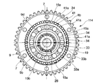
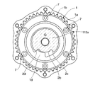
- FIG. 4 is a cross-sectional view of the variable valve timing device shown in FIG. 3, taken along the line AA.
- FIG. 4 is a sectional view taken along line BB of the variable valve timing device shown in FIG. 3.
- It is a functional block diagram which shows an aspect of the control function of ECM and an electric VTC controller. It is a functional block diagram of a VTC angle change amount calculation part and a VTC angle calculation part. It is a functional block diagram of a torque/rotation angle conversion unit.
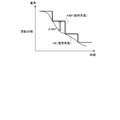
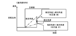
- FIG. 6 is a time chart showing an interpolation process based on the amount of change ⁇ RAP. It is a time chart which shows the mode of the amount of calibration at the time of advance operation.
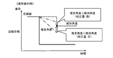
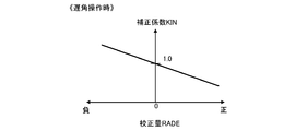
- FIG. 6 is a diagram showing a correlation between a calibration amount and a correction coefficient during an advance operation. It is a time chart which shows the mode of the amount of calibration at the time of retard operation.
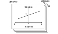
- FIG. 6 is a diagram showing a correlation between a calibration amount and a correction coefficient during a retard operation. It is a figure which shows the table which calculates
- FIG. 6 is a diagram for explaining a switching characteristic of a correction coefficient in the vicinity of a target value.
- 6 is a flowchart showing a correction coefficient setting process including switching of correction coefficients in the vicinity of a target value.
- 7 is a time chart showing changes in the calibration amount when the correction coefficient is excessive. It is a figure which shows the change of a correction coefficient table when a correction coefficient is excessive. It is a figure which shows the correction coefficient table which has a dead zone. 6 is a time chart for explaining learning of angle change estimation based on a motor drive current.
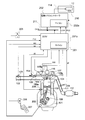
- FIG. 1 is a diagram showing one mode of an internal combustion engine for a vehicle provided with a variable valve timing device.
- the internal combustion engine 101 of FIG. 1 includes a flow rate sensor 103 in the intake duct 102, and the flow rate sensor 103 detects the intake air flow rate QA of the internal combustion engine 101.
- the intake valve 105 opens and closes the intake port of the combustion chamber 104 of each cylinder.
- the fuel injection valve 106 which is one mode of the fuel injection device, injects gasoline as fuel into the intake port 102a of each cylinder.
- the internal combustion engine 101 is a 4-stroke engine, and the piston 108 goes down to the top dead center to compress the air-fuel mixture during the intake stroke in which the piston 108 descends to suck the air containing fuel into the combustion chamber 104 via the intake valve 105.
- the air-fuel mixture ignited by the ignition plug 107 burns, the combustion gas expands and the piston 108 is pushed down to the bottom dead center, the piston 108 rises due to inertia, and the combustion gas burns through the exhaust valve 110.
- the exhaust process of pushing out toward the exhaust pipe 111 outside the chamber 104 is repeated.
- a catalytic converter 112 containing a catalyst such as a three-way catalyst is installed in the exhaust pipe 111.
- the intake valve 105 opens with the rotation of the intake camshaft 115a that is rotationally driven by the crankshaft 109.
- the exhaust valve 110 opens with the rotation of the exhaust camshaft 115b that is rotationally driven by the crankshaft 109.
- the variable valve timing device 114 is a device that continuously changes the valve timing of the intake valve 105, which is an engine valve, by changing the rotation phase of the intake camshaft 115a with respect to the crankshaft 109 according to the rotation speed of the motor 12 as an actuator.
- the motor 12 is, for example, a DC brush motor.
- the ignition module 116 is directly attached to the ignition plug 107 and supplies ignition energy to the ignition plug 107.
- the ignition module 116 includes an ignition coil and a power transistor that controls energization of the ignition coil.
- the control device that controls the operation of the internal combustion engine 101 includes an engine control module (hereinafter referred to as ECM) 201 that controls fuel injection by the fuel injection valve 106 and ignition by the spark plug 107, and a variable valve timing device 114.
- ECM engine control module
- An electric VTC controller 202 which is a control device for controlling is included.
- the ECM 201 is an electronic control device including a microcomputer 201a
- the electric VTC controller 202 is an electronic control device including a microcomputer 202a.
- the ECM 201 inputs signals from various sensors and performs arithmetic processing according to a program stored in a memory to calculate and output operation signals for the fuel injection valve 106, the ignition module 116, and the like. Further, the electric VTC controller 202 receives a signal transmitted by the ECM 201 and performs arithmetic processing according to a program stored in a memory, thereby calculating and outputting an operation signal of the variable valve timing device 114.
- the ECM 201 and the electric VTC controller 202 are configured to be able to communicate with each other via a communication circuit 211 such as a CAN (Controller Area Network).
- the internal combustion engine 101 includes, in addition to the flow rate sensor 103, a crank angle sensor 203 that outputs a crank angle signal POS at each predetermined angular position of the crankshaft 109, a depression amount of an accelerator pedal 207, in other words, an accelerator opening.
- Degree ACC for detecting the degree ACC
- a cam angle sensor 204 for outputting a cam angle signal CAM for each predetermined angular position of the intake camshaft 115a
- a water temperature sensor 208 for detecting the temperature TW of the cooling water of the internal combustion engine 101
- a catalyst The exhaust pipe 111 upstream of the converter 112 is provided with an air-fuel ratio sensor 209 for detecting the air-fuel ratio AF based on the oxygen concentration in the exhaust gas.
- the ECM 201 inputs signals from these various sensors, and further inputs signals from an ignition switch (in other words, engine switch) 205 which is a main switch for operating and stopping the internal combustion engine 101.
- an ignition switch in other words, engine switch
- the variable valve timing device 114 includes a current detector 210 that detects a drive current of the motor 12 (DC brush motor), and the electric VTC controller 202 includes a drive current detection signal (potential difference between both ends of the shunt resistor) output by the current detector 210. Signal).
- the electric VTC controller 202 adjusts the magnitude and direction of the drive current of the motor 12 by, for example, PWM-controlling a semiconductor switch forming an H-bridge circuit. Further, the electric VTC controller 202 controls the duty ratio in the PWM based on the difference between the detection value (control amount) regarding the rotation phase (valve timing) of the intake camshaft 115a with respect to the crankshaft 109 and the target value, thereby performing rotation. Perform phase feedback control.
- the electric VTC controller 202 determines the crank angle signal POS (rotation angle signal of the crankshaft 109) and the cam angle signal CAM (rotation angle signal of the intake camshaft 115a) duplicated by the ECM 201 in order to obtain the detection value regarding the rotation phase. ) Is input via a dedicated signal line.
- the electric VTC controller 202 can directly receive the rotation angle signal from the crank angle sensor 203 and the cam angle sensor 204.
- the ECM 201 calculates information about a target value (target rotation phase) in feedback control of the rotation phase based on engine operating conditions such as engine load and engine rotation speed, and sends information about the calculated target value to the communication circuit 211. Via the electric VTC controller 202.
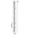
- FIG. 2 shows one aspect of output patterns of the crank angle signal POS and the cam angle signal CAM.
- the crank angle signal POS is a pulse signal for each unit crank angle, and the signal output pattern is set so that one or a plurality of continuous pulses are omitted for each crank angle corresponding to the stroke phase difference between the cylinders. I am doing it.
- the unit crank angle which is the output cycle of the crank angle signal POS is, for example, the crank angle of 10 deg CA.
- the stroke phase difference between the cylinders corresponds to the ignition interval, and the crank angle is 180 degCA in the 4-cylinder in-line engine.
- crank angle sensor 203 is a sensor that outputs a crank angle signal POS for each unit crank angle without setting a missing portion and a reference crank angle signal REF for each crank angle corresponding to a stroke phase difference between cylinders. be able to.
- the missing portion of the crank angle signal POS or the output position of the reference crank angle signal REF indicates that the piston of each cylinder is located at the reference piston position. That is, the ECM 201 uses the information on the missing portion of the crank angle signal POS to detect the reference crank angle position instead of the reference crank angle signal REF.
- the cam angle sensor 204 outputs the cam angle signal CAM for each crank angle corresponding to the stroke phase difference between the cylinders.
- the intake camshaft 115a rotates at a speed half that of the crankshaft 109. Therefore, when the internal combustion engine 101 is a 4-cylinder in-line engine and the crank angle corresponding to the stroke phase difference between the cylinders is 180 degCA, the crank angle 180 degCA corresponds to the rotation angle 90 deg of the intake camshaft 115a. That is, the cam angle sensor 204 outputs the cam angle signal CAM every time the intake camshaft 115a rotates 90 degrees.
- the ECM 201 executes a process (hereinafter, referred to as a cylinder discrimination process) for detecting a cylinder in which the piston position is the reference position based on the cam angle signal CAM output from the cam angle sensor 204.
- the cam angle sensor 204 outputs, for example, a cam angle signal CAM having a pulse number capable of distinguishing the cylinder number for each crank angle of 180 degCA in a 4-cylinder in-line engine.
- the cam angle sensor 204 outputs one pulse signal, two continuous pulse signals, two continuous pulse signals, and one pulse signal in this order for each crank angle of 180 degCA.
- the ECM 201 performs a cylinder discrimination process of discriminating in which of the four cylinders the piston is located at the reference piston position by counting the number of pulses of the cam angle signal CAM for each crank angle of 180 degCA. Then, the ECM 201 determines a cylinder on which fuel injection or ignition is performed based on the result of the cylinder discrimination processing, and controls the fuel injection valve 106 and the ignition module 116 for each cylinder.
- the number of pulses of the cam angle signal CAM for the cylinder discrimination process is not limited to the above pattern. Further, the output characteristic of the cam angle sensor 204 can be set so that the cylinder discrimination can be performed by the pulse width or the amplitude of the cam angle signal CAM.
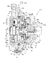
- variable valve timing device 114 shows one aspect of the structure of the variable valve timing device 114.
- the structure of the variable valve timing device 114 is not limited to that illustrated in FIGS. 3 to 5, and a known variable valve timing device that changes the rotational phase of the camshaft with respect to the crankshaft in accordance with the rotational speed of the motor is appropriately used. Can be adopted.
- the variable valve timing device 114 shown in FIG. 3 to FIG. 5 is rotatably supported on the cylinder head by a timing sprocket 1 that is a driving rotating body that is rotationally driven by the crankshaft 109 of the internal combustion engine 101 and a bearing 44.
- the intake camshaft 115a that is rotated by the rotational force transmitted from the timing sprocket 1, the cover member 3 that is arranged at the front position of the timing sprocket 1 and is fixed to the chain cover 40 by bolts, the timing sprocket 1 and the intake sprocket 1.
- a phase changing device 4 arranged between the camshafts 115a for changing the rotational phase of the intake camshaft 115a with respect to the timing sprocket 1.
- the timing sprocket 1 is composed of a sprocket body 1a and a gear portion 1b which is integrally provided on the outer periphery of the sprocket body 1a and receives a rotational force from the crankshaft 109 via the wound timing chain 42. .. Further, the timing sprocket 1 has a third ball interposed between a circular groove 1c formed on the inner circumference of the sprocket body 1a and an outer circumference of a flange portion 2a integrally provided at the front end of the intake camshaft 115a.
- the bearing 43 rotatably supports the intake camshaft 115a.
- annular protrusion 1e is integrally formed on the outer peripheral edge of the front end portion of the sprocket body 1a.
- annular member 19 coaxially positioned on the inner circumference of the annular protrusion 1e and having inner teeth 19a which are wavy meshing portions formed on the inner circumference, and an annular plate 6, The bolts 7 are fixed in the axial direction together.
- a stopper protrusion 1d which is an arc-shaped engaging portion, is formed over a predetermined range in the circumferential direction on a part of the inner peripheral surface of the sprocket body 1a.
- a cylindrical housing 5 is fixed to the outer periphery of the front end of the plate 6 with bolts 11 to cover the speed reducer 8 and the motor 12 that constitute the phase changing device 4.
- the motor 12 is an actuator of the variable valve timing device 114.
- the housing 5 is made of iron-based metal and functions as a yoke.
- the housing 5 integrally has an annular plate-shaped housing holding portion 5a at the front end, and the entire outer circumference including the housing holding portion 5a is covered by the cover member 3 with a predetermined gap. It is arranged to be covered with.
- the intake cam shaft 115a has a drive cam (not shown) on the outer circumference for opening the intake valve 105, and a driven member 9 which is a driven rotary body at the front end thereof is coupled from the axial direction by a cam bolt 10.
- the flange portion 2a of the intake camshaft 115a is provided with a stopper groove 2b, which is a locking portion into which the stopper protrusion 1d of the sprocket body 1a is engaged, along the circumferential direction.
- the stopper concave groove 2b is formed in an arc shape having a predetermined length along the circumferential direction, and both end edges of the stopper convex portion 1d rotated within this length range are opposed to the circumferential opposite edges 2c and 2d, respectively.
- the stopper protrusion 1d and the stopper groove 2b constitute a mechanical stopper
- the angular range in which the stopper protrusion 1d can move within the stopper groove 2b is the operating range of the variable valve timing device 114, in other words, the crank.
- This is the variable range of the rotational phase of the intake camshaft 115a with respect to the shaft 109.
- the position where the end edge of the stopper convex portion 1d contacts one of the opposing edges 2c and 2d of the stopper concave groove 2b becomes the most advanced position of the valve timing limited by the mechanical stopper, and the position where it contacts the other. , It is the most retarded position of valve timing limited by the mechanical stopper.
- a flange-shaped seat surface portion 10c is integrally formed at an end edge of the head portion 10a of the cam bolt 10.
- a male screw portion is formed on the outer periphery of the shaft portion 10b so as to be screwed from an end portion of the intake camshaft 115a to a female screw portion formed in the inner axial direction.
- the driven member 9 is made of an iron-based metal material and, as shown in FIG. 4, is composed of a disk portion 9a formed at the front end and a cylindrical cylindrical portion 9b integrally formed at the rear end. ..
- annular step projection 9c having substantially the same outer diameter as the flange portion 2a of the intake camshaft 115a is integrally provided on the disc portion 9a of the driven member 9 at a substantially radial center position of the rear end surface. Then, the outer peripheral surface of the annular step protrusion 9c and the outer peripheral surface of the flange portion 2a are arranged to be inserted through the inner periphery of the inner ring 43a of the third ball bearing 43. The outer ring 43b of the third ball bearing 43 is press-fitted and fixed to the inner peripheral surface of the circular groove 1c of the sprocket body 1a.
- a retainer 41 that holds the plurality of rollers 34 is integrally provided on the outer peripheral portion of the disk portion 9a of the driven member 9.
- the retainer 41 protrudes from the outer peripheral portion of the disc portion 9a in the same direction as the cylindrical portion 9b, and has a plurality of elongated protrusion portions 41a formed at predetermined circumferentially equidistant positions with predetermined gaps. ..
- the cylindrical portion 9b is formed with a through hole 9d through which the shaft portion 10b of the cam bolt 10 is inserted, and a first needle bearing 28 is provided on the outer periphery of the cylindrical portion 9b.
- the cover member 3 is made of a synthetic resin material and includes a cover body 3a that bulges like a cup and a bracket 3b that is integrally provided on the outer periphery of the rear end portion of the cover body 3a.
- the cover main body 3a is arranged so as to cover the front end of the phase changing device 4, that is, almost the entire axially holding portion 5b to the rear end portion of the housing 5 with a predetermined gap.
- the bracket 3b is formed in a substantially annular shape, and bolt insertion holes 3f are formed through the six boss portions, respectively.
- the bracket 3b is fixed to the chain cover 40 via a plurality of bolts 47, and inner and outer double slip rings 48a and 48b expose the inner end surfaces of the inner peripheral surface of the front end portion 3c of the cover body 3a. It is buried and fixed in the state. Further, a connector portion 49 having a connector terminal 49a connected to the slip rings 48a and 48b via a conductive member is provided at the upper end of the cover member 3. The connector terminal 49a is supplied with electric power from a battery power source (not shown) via the electric VTC controller 202.
- a first oil seal 50 which is a seal member, is interposed between the inner peripheral surface of the rear end portion of the cover body 3a and the outer peripheral surface of the housing 5.
- the first oil seal 50 has a substantially U-shaped cross section, and a core metal is embedded inside a synthetic rubber base material.
- the annular base portion 50a on the outer periphery of the first oil seal 50 is fitted and fixed in the circular groove 3d formed on the inner peripheral surface of the rear end portion of the cover body 3a. Further, on the inner circumference of the annular base portion 50a of the first oil seal 50, a seal surface 50b that abuts on the outer circumferential surface of the housing 5 is integrally formed.
- the phase changing device 4 is composed of a motor 12 arranged substantially coaxially with the front end of the intake camshaft 115a, and a speed reducer 8 that decelerates the rotation speed of the motor 12 and transmits it to the intake camshaft 115a.
- the motor 12 is a brushed DC motor (DC brush motor), and includes a housing 5 that is a yoke that rotates integrally with the timing sprocket 1, and a motor shaft that is an output shaft rotatably provided inside the housing 5. 13, a pair of semi-circular arc-shaped permanent magnets 14 and 15 fixed to the inner peripheral surface of the housing 5, and a stator 16 fixed to the inner bottom surface of the housing holding portion 5a.
- the motor shaft 13 is formed in a tubular shape and functions as an armature.
- An iron core rotor 17 having a plurality of poles is fixed to the outer periphery of the axial center, and an electromagnetic coil 18 is wound around the outer periphery of the iron core rotor 17.
- the commutator 20 is press-fitted and fixed to the outer periphery of the front end portion of the motor shaft 13, and the commutator 20 is connected with the electromagnetic coil 18 in each segment divided into the same number as the number of poles of the iron core rotor 17.
- the motor shaft 13 has a first needle bearing 28, which is a first bearing, and a fourth ball bearing 35, which is a bearing arranged on an axial side portion of the first needle bearing 28, on the outer peripheral surface of the shaft portion 10b. It is rotatably supported via. Further, a cylindrical eccentric shaft portion 30 forming a part of the speed reducer 8 is integrally provided at a rear end portion of the motor shaft 13.
- a second oil seal 32 is provided between the outer peripheral surface of the motor shaft 13 and the inner peripheral surface of the plate 6 to prevent the lubricating oil from leaking from the inside of the speed reducer 8 into the motor 12.
- the second oil seal 32 has an inner peripheral portion elastically contacting the outer peripheral surface of the motor shaft 13 to impart frictional resistance to the rotation of the motor shaft 13.
- the decelerator 8 includes an eccentric shaft portion 30 that performs eccentric rotary motion, a second ball bearing 33 that is a second bearing provided on the outer circumference of the eccentric shaft portion 30, and a roller provided on the outer circumference of the second ball bearing 33. 34, a retainer 41 that retains the roller 34 in the rolling direction and allows radial movement, and a driven member 9 that is integral with the retainer 41.
- the axis of the cam surface formed on the outer peripheral surface of the eccentric shaft portion 30 is slightly eccentric in the radial direction from the axis X of the motor shaft 13.
- the second ball bearing 33, the roller 34, etc. are configured as a planetary meshing portion.
- the second ball bearing 33 is arranged so as to be substantially entirely overlapped at the radial position of the first needle bearing 28.
- the inner ring 33a of the second ball bearing 33 is press-fitted and fixed to the outer peripheral surface of the eccentric shaft portion 30, and the roller 34 is always in contact with the outer peripheral surface of the outer ring 33b of the second ball bearing 33.
- An annular clearance C is formed on the outer periphery of the outer ring 33b, and the clearance C allows the entire second ball bearing 33 to move in the radial direction with the eccentric rotation of the eccentric shaft portion 30, that is, to allow eccentric movement. ing.
- Each roller 34 moves in the radial direction according to the eccentric movement of the second ball bearing 33 and fits into the internal tooth 19a of the annular member 19, and is also guided in the circumferential direction by the projection 41a of the retainer 41 in the radial direction. It is designed to swing.
- Lubricating oil is supplied to the inside of the speed reducer 8 by the lubricating oil supply means.
- the lubricating oil supply means is formed inside the bearing 44 of the cylinder head and is formed in the inner axial direction of the intake camshaft 115a and an oil supply passage 44a to which lubricating oil is supplied from a main oil gallery (not shown).
- An oil supply hole 48 communicating with the passage 44a through a groove groove is formed to penetrate the driven member 9 in the axial direction of the inner surface of the driven member 9, one end of which opens into the oil supply hole 48 and the other end of which is the first needle bearing 28 and the second ball bearing. It is composed of a small-diameter oil supply hole 45 opened near 33 and three large-diameter oil discharge holes (not shown) which are also formed through the driven member 9.
- variable valve timing device 114 The operation of the variable valve timing device 114 will be described below.
- the crankshaft 109 rotates, the timing sprocket 1 rotates via the timing chain 42, and the rotational force thereof causes the motor 12 to rotate synchronously via the housing 5, the annular member 19 and the plate 6.
- the rotational force of the annular member 19 is transmitted from the roller 34 to the intake camshaft 115a via the retainer 41 and the driven member 9, and the intake camshaft 115a rotates. Then, as the intake camshaft 115a rotates, the cam provided on the intake camshaft 115a opens and closes the intake valve 105.
- the electric VTC controller 202 energizes the motor 12 of the variable valve timing device 114 to generate torque when advancing or retarding the rotational phase of the intake camshaft 115a with respect to the crankshaft 109, that is, the valve timing of the intake valve 105. Let The output torque of the motor 12 is transmitted to the intake camshaft 115a via the speed reducer 8.
- each roller 34 is guided by the protrusion 41 a of the retainer 41 in each radial direction of the motor shaft 13 while being guided by one of the annular members 19. It moves over the inner teeth 19a while rolling while moving to the other adjacent inner teeth 19a, and rolling in the circumferential direction while repeating this in sequence.
- the rotation of the motor shaft 13 is decelerated by the rolling contact of the rollers 34, and the rotational force is transmitted to the driven member 9.
- the speed reduction ratio when the rotation of the motor shaft 13 is transmitted to the driven member 9 can be arbitrarily set depending on the number of rollers 34 and the like.
- the intake camshaft 115a rotates in the forward and reverse directions relative to the timing sprocket 1 and the rotational phase is converted, and the opening/closing timing (valve timing) of the intake valve 105 changes in the advance direction and the retard direction. That is, when the motor 12 receives the rotational driving force from the timing sprocket 1 and is driven to rotate and the motor shaft 13 rotates at the same rotational speed as the timing sprocket 1, the rotational phase of the intake camshaft 115 a with respect to the crankshaft 109 does not change. ..
- variable valve timing device 114 advances the valve timing in the advancing direction in accordance with the difference between the rotation amount of the motor shaft 13 and the rotation amount of the timing sprocket 1, in other words, the rotation speed of the motor shaft 13 with respect to the timing sprocket 1. It is a device that changes in the retard direction.
- the electric VTC controller 202 has a function as software that variably controls the rotational phase of the intake camshaft 115a with respect to the crankshaft 109 by adjusting the rotational speed of the motor 12.
- the electric VTC controller 202 performs feedback control of the rotational phase, which calculates the operation amount of the motor 12 so that the phase detection value RA approaches the target value TA.
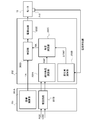
- FIG. 6 is a functional block diagram showing the control function of the variable valve timing device 114 in the ECM 201 and the electric VTC controller 202.
- the ECM 201 includes a VTC target value calculation unit 201A and a replication circuit 201B.
- the VTC target value calculation unit 201A calculates the target value TA of the rotation phase (in other words, the valve timing of the intake valve 105) based on the operating state of the internal combustion engine 101, such as the load and the rotation speed, and calculates the calculated target value TA. Is transmitted to the electric VTC controller 202.
- the duplication circuit 201B duplicates the crank angle signal POS output by the crank angle sensor 203 and the cam angle signal CAM output by the cam angle sensor 204, and outputs the duplicated crank angle signal POS and cam angle signal CAM to the electric VTC controller 202. Send to.
- the electric VTC controller 202 includes a VTC absolute angle calculation unit 202A, a VTC angle change amount calculation unit 202B, a VTC angle calculation unit 202C, a drive control unit 202D, and a motor drive circuit 202E.
- the VTC absolute angle calculation unit 202A, the VTC angle change amount calculation unit 202B, and the VTC angle calculation unit 202C configure a phase information acquisition unit that acquires phase information used for controlling the variable valve timing device 114.
- the VTC absolute angle calculation unit 202A calculates a phase detection value RAP, which is detection information of the absolute angle of the rotation phase, based on the crank angle signal POS and the cam angle signal CAM, which are duplicate signals transmitted by the ECM 201.
- the VTC absolute angle calculation unit 202A obtains the phase detection value RAP as the first phase information regarding the rotation phase based on the rotation angle signal of the crankshaft 109 and the rotation angle signal of the intake camshaft 115a (first step). ) Is carried out.
- the VTC absolute angle calculation unit 202A measures the crank angle [deg CA] from the reference crank angle position detected based on the crank angle signal POS until the cam angle signal CAM is input. Then, the phase detection value RAP [deg CA] of the intake camshaft 115a with respect to the crankshaft 109 is calculated.
- the VTC angle change amount calculation unit 202B calculates the rotation phase change amount ⁇ RAP per unit period based on the drive current of the motor 12 obtained from the output of the current detector 210. That is, the VTC angle change amount calculation unit 202B executes a process (second step) of obtaining the change amount ⁇ RAP, which is phase change information regarding the change amount of the rotation phase per unit period, based on the drive current of the motor 12.
- the VTC angle calculation unit 202C acquires the phase detection value RAP calculated by the VTC absolute angle calculation unit 202A and the change amount ⁇ RAP calculated by the VTC angle change amount calculation unit 202B, and between the update cycles of the phase detection value RAP.
- the final phase detection value RA is calculated by performing an interpolation process for obtaining the change in the rotation phase of the above based on the integrated value of the change amount ⁇ RAP. Then, when the phase detection value RAP is updated, the VTC angle calculation unit 202C carries out a calibration process of resetting the phase detection value RA to the phase detection value RAP.
- the VTC angle calculation unit 202C performs a process (third stage) of obtaining the phase detection value RA that is the second phase information regarding the rotation phase by interpolating the phase detection value RAP based on the change amount ⁇ RAP.
- the drive control unit 202D as an operation unit calculates the operation amount of the motor 12 based on the comparison between the phase detection value RA and the target value TA, and outputs the operation amount to the motor drive circuit 202E. That is, the drive control unit 202D performs a process (fifth step) of generating and outputting the operation signal of the motor 12 based on the comparison between the phase detection value RA and the target value TA.
- the motor drive circuit 202E outputs a drive voltage applied to the motor 12.
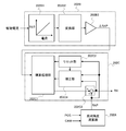
- FIG. 7 is a functional block diagram showing details of the VTC angle change amount calculation unit 202B and the VTC angle calculation unit 202C.
- the VTC angle change amount calculation unit 202B includes a current/torque conversion unit 202B1, a torque/rotation angle conversion unit 202B2, and a unit conversion unit 202B3.
- the current/torque conversion unit 202B1 converts the input motor drive current [A] into a motor torque [N ⁇ m] using a conversion table or a function having the motor drive current as a variable and outputs the motor torque.
- the torque/rotation angle conversion unit 202B2 obtains and outputs the motor rotation angle [deg] from the motor torque [N ⁇ m] calculated by the current/torque conversion unit 202B1.
- the unit conversion unit 202B3 converts the motor rotation angle [deg] calculated by the torque/rotation angle conversion unit 202B2 into the amount of change in the rotation phase per unit time (VTC angle change amount) ⁇ RAP [deg CA] to obtain the VTC angle. It is output to the arithmetic unit 202C.
- the change amount ⁇ RAP [deg CA] corresponds to phase change information that is information about the change amount of the rotation phase per unit period.
- FIG. 8 is a block diagram showing details of the torque/rotation angle conversion unit 202B2 for obtaining the motor rotation angle from the motor torque.
- the torque/rotation angle conversion unit 202B2 acquires information such as the motor torque [N ⁇ m], the cam torque [N ⁇ m], and the engine rotation speed [rpm].
- the torque/rotation angle conversion unit 202B2 obtains the torque acting on the change of the rotation phase based on the cam torque, the reduction ratio, and the gear efficiency, while obtaining the friction torque based on the engine rotation speed and the motor rotation angular velocity, and the motor By correcting the torque, the net motor torque that contributes to the change in the rotational phase is estimated. Then, the torque / rotation angle conversion portion 202B2 is, the motor torque, the rotor section moment of inertia, calculated motor rotation angular acceleration from the cam shaft inertia moment [rad / sec 2], the motor from the motor rotation angular acceleration [rad / sec 2] Calculate the rotational angular velocity [rad/sec]. Further, the torque/rotation angle conversion unit 202B2 obtains the motor rotation angle [rad] from the motor rotation angular velocity [rad/sec] and converts the motor rotation angle [rad] into the motor rotation angle [deg].
- the VTC angle calculation unit 202C includes an integration processing unit 202C1, a reset unit 202C2, an interpolation unit 202C3, and an estimated angle correction unit 202C4.
- the integration processing unit 202C1 integrates the change amount ⁇ RAP [deg CA] calculated by the VTC angle change amount calculation unit 202B.
- the reset unit 202C2 resets the integration result in the integration processing unit 202C1 to zero each time the phase detection value RAP [deg CA] is updated and calculated, in other words, each time the cam angle signal CAM is input.
- the interpolation unit 202C3 adds the integrated value [deg CA] of the variation ⁇ RAP obtained by the integration processing unit 202C1 to the phase detection value RAP [deg CA], and the addition result is the final phase detection.
- the VTC absolute angle calculation unit 202A updates and calculates the phase detection value RAP [deg CA] for each input of the cam angle signal CAM, but immediately after the update calculation until the next input of the cam angle signal CAM is calculated.
- the detected phase detection value RAP [deg CA] is held.
- the electric VTC controller 202 performs interpolation processing to estimate such a change in rotation phase from the motor drive current to control the motor.
- the phase detection value RA used for is shown to change close to the actual value.
- the estimated angle correction unit 202C4 shifts between the phase detection value RAP [deg CA] (absolute angle) at the time of updating and the phase detection value RA (estimated angle) immediately before being calibrated to the phase detection value RAP.
- a correction coefficient KIN correction value for correcting the phase detection value RA (estimated angle) until the phase detection value RAP [deg CA] is updated next time is set based on the calibration amount RADE.
- the estimated angle correction unit 202C4 corrects the phase detection value RA (estimated angle) with the obtained correction coefficient KIN, and calculates the operation amount of the motor 12 based on the corrected phase detection value RA (estimated angle). That is, the estimated angle correction unit 202C4 determines the correction coefficient KIN based on the calibration amount RADE when the phase detection value RAP [deg CA] is updated, and then corrects the phase detection value RA (estimated angle) using the correction coefficient KIN. It continues until the phase detection value RAP [deg CA] of is updated and the correction coefficient KIN is newly determined when the phase detection value RAP [deg CA] is updated.
- the estimated angle correction unit 202C4 uses the information of the change amount ⁇ RAP given to the VTC angle calculation unit 202C by the VTC angle change amount calculation unit 202B as the phase detection value RAP (absolute angle) at the update timing of the phase detection value RAP. And the phase detection value RA (estimated angle based on the amount of change ⁇ RAP), the VTC absolute angle calculation unit 202A changes the phase detection value RAP until the next update. , A process (fourth step) of changing the information of the amount of change ⁇ RAP used to obtain the phase detection value RA.
- the estimated angle correction unit 202C4 uses, for example, a VTC angle, a parameter that is multiplied by the correction coefficient KIN (a parameter that is directly corrected by the correction coefficient KIN) in the correction of the phase detection value RA (estimated angle) by the correction coefficient KIN. Any one or more of the change amount, the motor rotation speed, the motor torque, the motor drive current, and the like are set, and the estimated value (estimated angle) of the change amount of the rotation phase is corrected by the correction coefficient KIN.
- the estimated angle correction unit 202C4 estimates the change amount of the rotation phase in the update cycle of the phase detection value RAP [deg CA] (absolute angle) based on the motor drive current, the change amount of the rotation phase is smaller than the actual change amount. Based on the tendency to estimate small or large, the estimated value of the amount of change in the rotational phase is corrected by the correction coefficient KIN so as to approach the actual value, and as a result, the phase detection value RA (estimated angle) is actually rotated. Approach the phase.
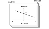
- 10 and 11 show the correlation between the correction amount RADE and the correction coefficient KIN during the operation of advancing the valve timing of the intake valve 105 (during the advancing operation).
- the most retarded position of the valve timing of the intake valve 105 is set as the reference position, and the rotation angle is represented by the advance angle from the reference position.
- the larger the estimation error the larger the absolute value of the calibration amount RADE becomes, and the negative value.
- the calibration amount RADE is information indicating the deviation amount between the absolute angle and the estimated angle and the deviation direction.
- the estimated angle correction unit 202C4 sets the correction coefficient KIN to a value smaller than 1.0 as the calibration amount RADE becomes smaller than zero, and then corrects the change amount ⁇ RAP [deg CA] by the set correction coefficient KIN. It is carried out until the detected value RAP (absolute angle) is updated.
- RAP absolute angle
- the phase detection value RAP [deg CA] is updated.
- the estimated angle correction unit 202C4 sets the correction coefficient KIN to a value larger than 1.0 as the calibration amount RADE becomes larger than zero.
- the advance angle change can be estimated to be larger, and the error in the estimated angle can be reduced.
- the phase detection value RAP [deg CA] is updated, the relationship of “estimated angle ⁇ absolute angle” is established, and when the calibration amount RADE is substantially zero, there is almost no estimation error and it is necessary to correct the estimated angle. Since there is almost nothing, the estimated angle correction unit 202C4 sets the correction coefficient KIN to 1.0 at which no substantial correction is performed when the calibration amount RADE is zero. Further, after the phase detection value RA converges to the target value TA and before the target value TA is changed next, the estimated angle correction unit 202C4 can stop the correction by the correction coefficient KIN.
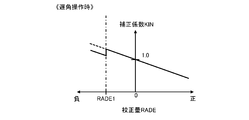
- the estimated angle correction unit 202C4 sets the correction coefficient KIN to a value larger than 1.0 as the calibration amount RADE becomes smaller than zero.
- the change amount ⁇ RAP [deg CA] based on the motor drive current tends to show a retard angle change smaller than the actual value
- the retard angle change can be estimated to be larger, and the error of the estimated angle can be reduced.
- the estimated angle correction unit 202C4 sets the correction coefficient KIN to a value smaller than 1.0 as the calibration amount RADE becomes larger than zero.
- the retard angle change can be estimated to be smaller and the error in the estimated angle can be reduced.
- the estimated angle correction unit 202C4 determines the magnitude and direction of the error of the estimated angle based on the calibration amount RADE, and corrects the estimated angle so that the error becomes smaller. Therefore, even if there is an error in the estimation of the rotation phase change based on the motor drive current, such an error can be compensated for, and the occurrence of overshoot and undershoot in feedback control of the rotation phase can be suppressed.
- the estimated angle correction unit 202C4 implements/stops the correction process of the change amount ⁇ RAP based on the calibration amount RADE or switches the correction degree according to the engine speed, thereby improving the accuracy of the interpolation process (estimated angle) and the calculation load. Can be reduced.
- the estimated angle correction unit 202C4 changes based on the calibration amount RADE when the engine rotation speed exceeds the threshold value (in other words, when the update cycle of the phase detection value RAP (absolute angle) is shorter than the threshold value).
- the correction processing of the amount ⁇ RAP is stopped and the engine speed is equal to or lower than the threshold value (in other words, the update cycle of the phase detection value RAP (absolute angle) is equal to or higher than the threshold value)
- the change based on the calibration amount RADE A correction process for the amount ⁇ RAP can be performed.
- the electric VTC controller 202 can prevent unnecessary interpolation calculation in a high rotation range where the effectiveness of interpolation is low, and can reduce the calculation load.
- the estimation angle correction unit 202C4 is configured as shown in FIGS. 14 and 15. Further, a correction coefficient table for advancing operation and a correction coefficient table for retarding operation are provided for each of a plurality of different engine rotational speed conditions, and the engine rotational speed (phase detection value RAP (absolute The correction coefficient KIN can be determined by referring to the correction coefficient table selected based on the update cycle) of the angle.
- the estimation error is likely to be accumulated and is easily affected by the estimation error.
- the estimated angle correction unit 202C4 sets the correction coefficient KIN according to the calibration amount RADE and the engine rotation speed, so that the correction coefficient KIN (correction value, correction degree) is appropriately set even under different engine rotation speed conditions. As a result, it is possible to prevent the correction from becoming insufficient. Further, the estimated angle correction unit 202C4 is a motor drive condition other than the engine rotation speed and affects operating conditions that affect the estimation accuracy of the rotation phase change based on the motor drive current (oil water temperature of the internal combustion engine 101, power supply voltage of the motor 12). , The energization history of the motor 12) and the calibration amount RADE can be used to calculate the correction coefficient KIN.
- the estimated angle correction unit 202C4 acts such that the operating conditions (influence factors such as oil/water temperature, power supply voltage, energization history, etc.) estimate the change amount ⁇ RAP per unit time to be larger than actual, or more than actual. It is possible to change the characteristic of the correction coefficient KIN according to the calibration amount RADE (and the engine rotation speed) depending on whether or not it acts so as to be estimated small. Further, when the estimated angle correction unit 202C4 sets the correction coefficient KIN based on the calibration amount RADE when updating the phase detection value RAP (absolute angle) and holds the correction coefficient KIN until the next update timing, the correction by the correction coefficient KIN is performed. May impair the convergence to the target value TA.
- the estimated angle correction unit 202C4 sets the correction coefficient KIN set based on the calibration amount RADE when updating the phase detection value RAP (absolute angle) to the phase detection value RA and the target value without waiting for the next update of the absolute angle.
- the correction coefficient KIN is set to a value larger than 1.0, After that, the amount of change ⁇ RAP is increased and corrected (see FIGS. 12 and 13).
- the increase correction of the change amount ⁇ RAP is estimated to be the actual angle.
- the deviation from the angle is increased to act in the direction of promoting undershoot (hunting phenomenon) (see FIGS. 16 and 17). That is, when the change in the rotational phase is estimated to be smaller than the actual value, the increase correction of the change amount ⁇ RAP by the correction coefficient KIN may promote undershoot (hunting phenomenon), and the increase correction of the change amount ⁇ RAP by the correction coefficient KIN may be performed. To reduce or stop the action of suppressing the undershoot (hunting phenomenon).
- the correction coefficient KIN is set to a value smaller than 1.0, and then the change amount ⁇ RAP is reduced and corrected, but in the vicinity of the target value TA, the change amount ⁇ RAP is set. If it is further reduced, it will act in the direction of suppressing undershoot (hunting phenomenon). Therefore, when the estimated angle correction unit 202C4 detects that the phase detection value RA is in a predetermined vicinity of the target value TA, the correction coefficient KIN (in other words, a change) in the direction of suppressing undershoot (hunting phenomenon). The change degree of the amount ⁇ RAP) is switched.
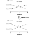
- FIG. 18 is a diagram for explaining the concept of switching processing of the correction coefficient KIN near the target value TA.
- the estimated angle correction unit 202C4 switches from the correction coefficient table B to the correction coefficient table A when the target position is approached, so that the same calibration amount RADE is obtained.
- the correction coefficient KIN is brought close to 1.0, and the increase correction of the change amount ⁇ RAP by the correction coefficient KIN is reduced.
- the estimated angle correction unit 202C4 switches from the correction coefficient table A to the correction coefficient table B when the target angle is approached, so that the same calibration amount RADE is obtained.
- the correction coefficient KIN in step 1 is moved away from 1.0, and the reduction correction of the change amount ⁇ RAP by the correction coefficient KIN is increased.
- FIG. 19 is a flowchart showing the flow of the process of setting the correction coefficient KIN by the estimated angle correction unit 202C4.
- the estimated angle correction unit 202C4 determines in step S501 whether or not the rotation phase has exceeded the target value TA (overshoot state) (see FIG. 17).
- the estimated angle correction unit 202C4 proceeds to step S502 and switches the correction coefficient KIN according to the condition of estimating the change of the rotational phase to be larger or smaller than the actual value.
- the estimated angle correction unit 202C4 proceeds from step S501 to step S503, and the rotation phase is in the vicinity of a predetermined target value TA (whether the rotation phase is a state immediately before reaching the target value TA or not). Is determined (see FIG. 16).
- the estimated angle correction unit 202C4 proceeds to step S504 and corrects it according to the condition of estimating the change of the rotation phase larger or smaller than the actual value. Switch the coefficient KIN. Note that the estimated angle correction unit 202C4 switches the correction coefficient KIN in step S504 when the rotation phase approaches a predetermined target value TA, and then proceeds to step S502 when an overshoot has occurred and proceeds to step S104. Based on the correction coefficient KIN switched in step 1, the correction coefficient KIN is further changed in the same direction.
- the estimated angle correction unit 202C4 determines the angle conversion state in steps S501 and S503 by determining the correlation between the target value TA and the current angle (absolute angle and/or estimated angle), and the correlation between the motor operation amount and the target value TA. , The estimated angle change speed/acceleration, the motor rotation speed, and the like.
- the estimated angle correction unit 202C4 proceeds from step S505 to step S506 to set the correction coefficient KIN based on the calibration amount RADE (error magnitude and direction). If the estimated angle correction unit 202C4 determines in step S505 that the calibration timing has not come, the estimated angle correction unit 202C4 proceeds to step S507 and holds the current correction coefficient KIN. As described above, the estimated angle correction unit 202C4 updates and sets the correction coefficient KIN at the calibration timing, and improves the convergence stability to the target value TA if the target value TA is approached during the calibration timing. Switch KIN.
- the estimated angle correction unit 202C4 switches the sign of the calibration amount RADE when the advance operation or the retard operation is continuously performed in the update setting of the correction coefficient KIN at the calibration timing (in other words, The direction of the estimation error is switched) and overcorrection is determined, and the correction coefficient table can be updated (correction of the correlation between the calibration amount RADE and the correction coefficient KIN).
- the update processing of the correction coefficient table will be described below with reference to FIGS. 20 and 21.
- the phase detection value RAP [deg CA] absolute angle
- the calibration amount RADE(1) becomes negative, and 1.0 A larger correction coefficient KIN(1) is set.
- the phase detection value RAP [deg CA] absolute angle
- the estimated angle correction unit 202C4 updates the correction coefficient table to be referred to in order to suppress excessive correction.
- the correction coefficient KIN is set to a larger value as the calibration amount RADE becomes smaller, the estimated angle correction unit 202C4 estimates that the correction amount is overcorrected at least in the region of the calibration amount RADE(1) or less, The correction coefficient KIN in the region of RADE(1) or less can be uniformly shifted in the decreasing direction by a constant value.
- updating of the correction coefficient table for overcorrection is not limited to the shift correction shown in FIG. 21, but may be, for example, tilt correction. Further, in the shift correction as shown in FIG. 21, the correction coefficient KIN can be updated so as to gradually change in the vicinity of the calibration amount RADE(1).
- the correction coefficient KIN is not limited to the configuration obtained by a linear function having the calibration amount RADE as a variable, and the correlation between the correction coefficient KIN and the calibration amount RADE can be set arbitrarily.
- the calibration amount RADE when the calibration amount RADE is within a predetermined range including 0, a dead zone in which the correction coefficient KIN is held at 1.0 can be provided, and the size of the dead zone can be changed to the angle conversion start. It can be made variable according to the response state of whether or not it is time, the operating state (engine speed, power supply voltage of the motor 12, oil/water temperature of the internal combustion engine 101) and the like.
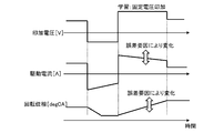
- the electric VTC controller 202 can include a learning function (learning unit) for learning each parameter used by the VTC angle change amount calculation unit 202B to estimate the change amount ⁇ RAP from the motor drive current.
- the electric VTC controller 202 applies a constant voltage to the motor 12, as shown in FIG. 23, in a steady state in which the oil/water temperature of the internal combustion engine 101, the motor power supply voltage, the rotation speed of the internal combustion engine 101, etc. are set values.
- the parameter value (electrical resistance, friction, etc.) used in the estimation process can be learned based on the motor drive current and the rotation phase change at that time.
- the electric VTC controller 202 can compensate the estimation error due to variations in the internal combustion engine 101 and the variable valve timing device 114, operating environment, aging, and the like.
- the correction coefficient KIN can be corrected until the learning is completed, and the correction coefficient KIN can be stopped after the learning is completed. That is, before the learning is completed, the error in the estimated angle is compensated by the correction coefficient KIN based on the calibration amount RADE, and if the error in the estimated angle becomes sufficiently small after the learning is completed, the correction request by the correction coefficient KIN becomes small. Even if the correction by the correction coefficient KIN is stopped, the rotation phase can be controlled with high accuracy.
- the ECM 201 can obtain the phase detection value RAP [deg CA] (absolute angle), and can transmit the obtained phase detection value RAP to the electric VTC controller 202. Further, the electric VTC controller 202 can determine the correction coefficient KIN for each elapsed time from the current update timing based on the calibration amount RADE at the update timing of the phase detection value RAP [deg CA] (absolute angle). That is, the correction coefficient KIN is not limited to the configuration in which the change amount ⁇ RAP is corrected with the constant correction coefficient KIN between the current update timing and the next update timing, and the correction coefficient KIN is corrected between the current update timing and the next update timing. Can be changed.
- variable valve timing device 114 is not limited to the device shown in FIGS. 3 to 5, and is disclosed in, for example, Japanese Unexamined Patent Application Publication No. 2008-069719, a sprocket, a cam plate, a link device, a guide plate, a speed reducer, Also, a variable valve timing device including a motor and the like can be adopted. Further, the variable valve timing device 114 can be provided in the internal combustion engine 101 as a device that changes the rotational phase of the exhaust camshaft 115b with respect to the crankshaft 109. In this case as well, the ECM 201 and the electric VTC controller 202 are the same as those described above. The variable valve timing device 114 can be controlled by the configuration and processing to achieve the same operational effect.
- the electric VTC controller 202 can continue the correction by the correction coefficient KIN based on the calibration amount RADE even after the learning is completed. it can.
- the electric VTC controller 202 changes the correction degree by the correction coefficient KIN to a small degree in the case of continuing the correction by the correction coefficient KIN even after the learning is completed, or re-learns when the calibration amount RADE exceeds the threshold value. You can Further, the electric VTC controller 202 can stop the interpolation process based on the change amount ⁇ RAP when the calibration amount RADE exceeds the threshold value.
Landscapes
- Engineering & Computer Science (AREA)
- Mechanical Engineering (AREA)
- General Engineering & Computer Science (AREA)
- Chemical & Material Sciences (AREA)
- Combustion & Propulsion (AREA)
- Valve Device For Special Equipments (AREA)
- Output Control And Ontrol Of Special Type Engine (AREA)
Abstract
本願発明に係る可変バルブタイミング装置の制御装置及び制御方法は、クランクシャフトの回転角信号とカムシャフトの回転角信号とに基づき求めた回転位相の絶対角度を、モータの駆動電流に基づき求めた回転位相の変化量に基づき補間する制御装置及び制御方法であって、絶対角度の更新時における絶対角度と補間による推定角度とのずれに基づき、絶対角度が次に更新されるまでの間でモータの駆動電流に基づく回転位相の変化量の推定を補正することで、バルブタイミング制御におけるオーバーシュート、アンダーシュートを抑制する。
Description
本発明は、可変バルブタイミング装置の制御装置及び制御方法に関し、詳しくは、実際の回転位相を求める技術に関する。
特許文献1が開示する可変バルブタイミング装置は、内燃機関の高回転域では、クランクシャフトとカムシャフトとの回転位相差に基づいてバルブタイミングを検出し、内燃機関の低回転域では、モータ回転角信号により検知されるアクチュエータの作動量に基づいて回転位相変化量を逐次演算し、回転位相変化量の積算値に基づいて実際のバルブタイミングを検出する。
ところで、可変バルブタイミング装置の制御装置が、モータの駆動電流に基づき回転位相変化量を演算する場合、モータ回転角信号に基づき回転位相変化量を演算する場合に比べて変化量の演算精度が低下し、バルブタイミングの制御においてオーバーシュート、アンダーシュートが発生し易くなるという問題があった。
本発明は、従来の実情に鑑みてなされたものであり、その目的は、モータの駆動電流に基づき回転位相の変化量を求める場合に、オーバーシュート、アンダーシュートの発生を抑制できる、可変バルブタイミング装置の制御装置及び制御方法を提供することにある。
そのため、本願発明に係る可変バルブタイミング装置の制御装置は、その一態様として、内燃機関のクランクシャフトに対するカムシャフトの回転位相に関する情報である第1位相情報を前記クランクシャフトの回転角信号と前記カムシャフトの回転角信号とに基づき求め、前記回転位相の単位期間当たりの変化量に関する情報である位相変化情報を可変バルブタイミング装置のモータの駆動電流に基づき求め、前記回転位相に関する情報である第2位相情報を、前記第1位相情報と前記位相変化情報とに基づき求める位相情報取得部と、前記位相情報取得部が前記第2位相情報の取得に用いる前記位相変化情報を、前記第1位相情報の更新タイミングでの前記第1位相情報と前記第2位相情報とのずれに基づき前記第1位相情報が次に更新されるまでの間において変更する変更部と、前記モータの操作信号を前記第2位相情報と目標値との比較に基づき生成して出力する操作部と、を備える。
また、本願発明に係る可変バルブタイミング装置の制御方法は、その一態様として、内燃機関のクランクシャフトに対するカムシャフトの回転位相に関する情報である第1位相情報を、前記クランクシャフトの回転角信号と前記カムシャフトの回転角信号とに基づき求める第1段階と、前記回転位相の単位期間当たりの変化量に関する情報である位相変化情報を、可変バルブタイミング装置のモータの駆動電流に基づき求める第2段階と、前記回転位相に関する情報である第2位相情報を、前記第1位相情報と前記位相変化情報とに基づき求める第3段階と、前記第3段階において前記第2位相情報の取得に用いる前記位相変化情報を、前記第1位相情報の更新タイミングでの前記第1位相情報と前記第2位相情報とのずれに基づき前記第1取得段階が前記第1位相情報を次に更新するまでの間において変更する第4段階と、前記モータの操作信号を前記第2位相情報と目標値との比較に基づき生成して出力する第5段階と、を含む。
上記発明によると、クランクシャフトの回転角信号とカムシャフトの回転角信号とに基づき求めた回転位相に関する情報と、モータの駆動電流に基づき求めた回転位相の変化量に関する情報とから、モータ制御に用いる回転位相の情報を求めるときに、回転位相情報の取得精度が向上し、回転位相のオーバーシュート、アンダーシュートの発生を抑制できる。
以下に本発明の実施の形態を説明する。
図1は、可変バルブタイミング装置を備えた車両用内燃機関の一態様を示す図である。
図1の内燃機関101は、吸気ダクト102に流量センサ103を備え、流量センサ103は、内燃機関101の吸入空気流量QAを検出する。
図1は、可変バルブタイミング装置を備えた車両用内燃機関の一態様を示す図である。
図1の内燃機関101は、吸気ダクト102に流量センサ103を備え、流量センサ103は、内燃機関101の吸入空気流量QAを検出する。
吸気バルブ105は、各気筒の燃焼室104の吸気口を開閉する。
燃料噴射装置の一態様である燃料噴射弁106は、各気筒の吸気ポート102a内に燃料としてのガソリンを噴射する。
燃料噴射装置の一態様である燃料噴射弁106は、各気筒の吸気ポート102a内に燃料としてのガソリンを噴射する。
内燃機関101は、4ストローク機関であり、ピストン108が下がって燃料を含んだ空気を吸気バルブ105を介して燃焼室104内に吸い込む吸入行程、ピストン108が上死点まで上がり混合気を圧縮する圧縮行程、点火プラグ107により点火された混合気が燃焼し、燃焼ガスが膨張してピストン108が下死点まで押し下げられる燃焼行程、慣性によりピストン108が上がり燃焼ガスを排気バルブ110を介して燃焼室104の外の排気管111に向けて押し出す排気行程を繰り返す。
三元触媒などの触媒を内蔵する触媒コンバータ112は排気管111に設置される。
吸気バルブ105は、クランクシャフト109によって回転駆動される吸気カムシャフト115aの回転に伴って開動作する。また、排気バルブ110は、クランクシャフト109によって回転駆動される排気カムシャフト115bの回転に伴って開動作する。
吸気バルブ105は、クランクシャフト109によって回転駆動される吸気カムシャフト115aの回転に伴って開動作する。また、排気バルブ110は、クランクシャフト109によって回転駆動される排気カムシャフト115bの回転に伴って開動作する。
可変バルブタイミング装置114は、アクチュエータとしてのモータ12の回転速度によってクランクシャフト109に対する吸気カムシャフト115aの回転位相を変化させることで、機関バルブである吸気バルブ105のバルブタイミングを連続的に変化させる装置である。
なお、モータ12は、例えば、DCブラシモータである。
また、点火モジュール116は点火プラグ107に直付けされ、点火プラグ107に点火エネルギーを供給する。点火モジュール116は、点火コイル及び点火コイルへの通電を制御するパワートランジスタを備える。
なお、モータ12は、例えば、DCブラシモータである。
また、点火モジュール116は点火プラグ107に直付けされ、点火プラグ107に点火エネルギーを供給する。点火モジュール116は、点火コイル及び点火コイルへの通電を制御するパワートランジスタを備える。
内燃機関101の運転を制御する制御装置は、燃料噴射弁106による燃料噴射や点火プラグ107による点火などを制御するエンジン・コントロール・モジュール(以下、ECMと称する)201と、可変バルブタイミング装置114を制御する制御装置である電動VTCコントローラ202とを含む。
ECM201は、マイクロコンピュータ201aを備えた電子制御装置であり、電動VTCコントローラ202は、マイクロコンピュータ202aを備えた電子制御装置である。
ECM201は、マイクロコンピュータ201aを備えた電子制御装置であり、電動VTCコントローラ202は、マイクロコンピュータ202aを備えた電子制御装置である。
ECM201は、各種センサの信号を入力し、メモリに格納されたプログラムに従って演算処理を行うことで、燃料噴射弁106、点火モジュール116などの操作信号を演算して出力する。
また、電動VTCコントローラ202は、ECM201が送信する信号などを受け、メモリに格納されたプログラムに従って演算処理を行うことで、可変バルブタイミング装置114の操作信号を演算して出力する。
ECM201と電動VTCコントローラ202とは、CAN(Controller Area Network)などの通信回路211を介して相互に通信可能に構成される。
また、電動VTCコントローラ202は、ECM201が送信する信号などを受け、メモリに格納されたプログラムに従って演算処理を行うことで、可変バルブタイミング装置114の操作信号を演算して出力する。
ECM201と電動VTCコントローラ202とは、CAN(Controller Area Network)などの通信回路211を介して相互に通信可能に構成される。
上記の各種センサとして、内燃機関101は、流量センサ103の他、クランクシャフト109の所定角度位置毎にクランク角信号POSを出力するクランク角センサ203、アクセルペダル207の踏込み量、換言すればアクセル開度ACCを検出するアクセル開度センサ206、吸気カムシャフト115aの所定角度位置毎にカム角信号CAMを出力するカム角センサ204、内燃機関101の冷却水の温度TWを検出する水温センサ208、触媒コンバータ112の上流の排気管111に設置され、排気中の酸素濃度に基づいて空燃比AFを検出する空燃比センサ209などを備える。
ECM201は、これら各種センサの信号を入力し、更に、内燃機関101の運転及び停止のメインスイッチであるイグニッションスイッチ(換言すれば、エンジンスイッチ)205の信号を入力する。
ECM201は、これら各種センサの信号を入力し、更に、内燃機関101の運転及び停止のメインスイッチであるイグニッションスイッチ(換言すれば、エンジンスイッチ)205の信号を入力する。
可変バルブタイミング装置114は、モータ12(DCブラシモータ)の駆動電流を検出する電流検出器210を備え、電動VTCコントローラ202は、電流検出器210が出力する駆動電流検出信号(シャント抵抗両端の電位差信号)を読み込む。
電動VTCコントローラ202は、モータ12の駆動電流の大きさ及び方向を、例えば、Hブリッジ回路を構成する半導体スイッチをPWM制御することで調整する。
また、電動VTCコントローラ202は、PWMにおけるデューティ比を、クランクシャフト109に対する吸気カムシャフト115aの回転位相(バルブタイミング)に関する検出値(制御量)と目標値との差に基づき制御することで、回転位相のフィードバック制御を実施する。
電動VTCコントローラ202は、モータ12の駆動電流の大きさ及び方向を、例えば、Hブリッジ回路を構成する半導体スイッチをPWM制御することで調整する。
また、電動VTCコントローラ202は、PWMにおけるデューティ比を、クランクシャフト109に対する吸気カムシャフト115aの回転位相(バルブタイミング)に関する検出値(制御量)と目標値との差に基づき制御することで、回転位相のフィードバック制御を実施する。
ここで、電動VTCコントローラ202は、回転位相に関する検出値を求めるために、ECM201が複製したクランク角信号POS(クランクシャフト109の回転角信号)及びカム角信号CAM(吸気カムシャフト115aの回転角信号)を、専用の信号線を介して入力する。なお、電動VTCコントローラ202は、クランク角センサ203、カム角センサ204から回転角信号を直接受け取ることができる。
また、ECM201は、機関負荷、機関回転速度などの機関運転条件に基づき、回転位相のフィードバック制御における目標値(目標回転位相)に関する情報を演算し、演算した目標値に関する情報を、通信回路211を介して電動VTCコントローラ202に送信する。
また、ECM201は、機関負荷、機関回転速度などの機関運転条件に基づき、回転位相のフィードバック制御における目標値(目標回転位相)に関する情報を演算し、演算した目標値に関する情報を、通信回路211を介して電動VTCコントローラ202に送信する。
図2は、クランク角信号POS及びカム角信号CAMの出力パターンの一態様を示す。
クランク角信号POSは、単位クランク角毎のパルス信号であって、気筒間の行程位相差に相当するクランク角毎に、1個若しくは連続する複数個のパルスが欠落するように信号出力パターンを設定してある。
クランク角信号POSの出力周期である単位クランク角は、例えばクランク角10deg CAである。また、気筒間の行程位相差は点火間隔に相当し、4気筒直列機関ではクランク角180degCAになる。
クランク角信号POSは、単位クランク角毎のパルス信号であって、気筒間の行程位相差に相当するクランク角毎に、1個若しくは連続する複数個のパルスが欠落するように信号出力パターンを設定してある。
クランク角信号POSの出力周期である単位クランク角は、例えばクランク角10deg CAである。また、気筒間の行程位相差は点火間隔に相当し、4気筒直列機関ではクランク角180degCAになる。
なお、クランク角センサ203を、欠落箇所の設定がない単位クランク角毎のクランク角信号POS、及び、気筒間の行程位相差に相当するクランク角毎の基準クランク角信号REFを出力するセンサとすることができる。
ここで、クランク角信号POSの欠落箇所若しくは基準クランク角信号REFの出力位置は、各気筒のピストンが基準ピストン位置に位置していることを示す。つまり、ECM201は、クランク角信号POSの欠落箇所の情報を、基準クランク角信号REFの代わりに基準クランク角位置の検出に用いる。
ここで、クランク角信号POSの欠落箇所若しくは基準クランク角信号REFの出力位置は、各気筒のピストンが基準ピストン位置に位置していることを示す。つまり、ECM201は、クランク角信号POSの欠落箇所の情報を、基準クランク角信号REFの代わりに基準クランク角位置の検出に用いる。
一方、カム角センサ204は、気筒間の行程位相差に相当するクランク角毎にカム角信号CAMを出力する。
吸気カムシャフト115aは、クランクシャフト109の回転速度の半分の速度で回転する。このため、内燃機関101が4気筒直列機関で、気筒間の行程位相差に相当するクランク角が180degCAである場合、クランク角180degCAは吸気カムシャフト115aの回転角90degに相当することになる。つまり、カム角センサ204は、吸気カムシャフト115aが90deg回転する毎にカム角信号CAMを出力する。
吸気カムシャフト115aは、クランクシャフト109の回転速度の半分の速度で回転する。このため、内燃機関101が4気筒直列機関で、気筒間の行程位相差に相当するクランク角が180degCAである場合、クランク角180degCAは吸気カムシャフト115aの回転角90degに相当することになる。つまり、カム角センサ204は、吸気カムシャフト115aが90deg回転する毎にカム角信号CAMを出力する。
ECM201は、カム角センサ204が出力するカム角信号CAMに基づき、ピストン位置が基準位置になっている気筒を検出する処理(以下、気筒判別処理という)を実施する。
上記気筒判別処理のため、カム角センサ204は、例えば、4気筒直列機関においてクランク角180degCA毎に気筒番号を区別できるパルス数のカム角信号CAMを出力する。
一例として、カム角センサ204は、クランク角180degCA毎に、1個のパルス信号、連続する2個のパルス信号、連続する2個のパルス信号、1個のパルス信号をこの順で出力する。
上記気筒判別処理のため、カム角センサ204は、例えば、4気筒直列機関においてクランク角180degCA毎に気筒番号を区別できるパルス数のカム角信号CAMを出力する。
一例として、カム角センサ204は、クランク角180degCA毎に、1個のパルス信号、連続する2個のパルス信号、連続する2個のパルス信号、1個のパルス信号をこの順で出力する。
ECM201は、クランク角180degCA毎にカム角信号CAMのパルス数を計数することで、4気筒のうちのいずれの気筒でピストンが基準ピストン位置に位置しているかを判別する気筒判別処理を実施する。
そして、ECM201は、気筒判別処理の結果に基づき、燃料噴射や点火を行わせる気筒を決定し、燃料噴射弁106、点火モジュール116を気筒別に制御する。
そして、ECM201は、気筒判別処理の結果に基づき、燃料噴射や点火を行わせる気筒を決定し、燃料噴射弁106、点火モジュール116を気筒別に制御する。
なお、気筒判別処理のためのカム角信号CAMのパルス数の設定は上記のパターンに限定されるものではない。
また、カム角信号CAMのパルス幅や振幅で気筒判別が実施できるように、カム角センサ204の出力特性を設定することができる。
また、カム角信号CAMのパルス幅や振幅で気筒判別が実施できるように、カム角センサ204の出力特性を設定することができる。
図3-図5は、可変バルブタイミング装置114の構造の一態様を示す。
但し、可変バルブタイミング装置114の構造は、図3-図5に例示したものに限定されず、モータの回転速度によってクランクシャフトに対するカムシャフトの回転位相を可変とする公知の可変バルブタイミング装置を適宜採用できる。
但し、可変バルブタイミング装置114の構造は、図3-図5に例示したものに限定されず、モータの回転速度によってクランクシャフトに対するカムシャフトの回転位相を可変とする公知の可変バルブタイミング装置を適宜採用できる。
図3-図5に示した可変バルブタイミング装置114は、内燃機関101のクランクシャフト109によって回転駆動される駆動回転体であるタイミングスプロケット1と、シリンダヘッド上に軸受44を介して回転自在に支持され、タイミングスプロケット1から伝達された回転力によって回転する吸気カムシャフト115aと、タイミングスプロケット1の前方位置に配置されて、チェーンカバー40にボルトによって固定されたカバー部材3と、タイミングスプロケット1と吸気カムシャフト115aの間に配置されて、タイミングスプロケット1に対する吸気カムシャフト115aの回転位相を変更する位相変更装置4と、を備える。
タイミングスプロケット1は、スプロケット本体1aと、スプロケット本体1aの外周に一体に設けられて、巻回されたタイミングチェーン42を介してクランクシャフト109からの回転力を受けるギア部1bと、で構成される。
また、タイミングスプロケット1は、スプロケット本体1aの内周に形成された円形溝1cと吸気カムシャフト115aの前端部に一体に設けられたフランジ部2aの外周との間に介装された第3ボールベアリング43によって、吸気カムシャフト115aに回転自在に支持されている。
また、タイミングスプロケット1は、スプロケット本体1aの内周に形成された円形溝1cと吸気カムシャフト115aの前端部に一体に設けられたフランジ部2aの外周との間に介装された第3ボールベアリング43によって、吸気カムシャフト115aに回転自在に支持されている。
スプロケット本体1aの前端部外周縁には、環状突起1eが一体に形成されている。
スプロケット本体1aの前端部には、環状突起1eの内周に同軸に位置決めされ内周に波形状の噛み合い部である内歯19aが形成された環状部材19と、円環状のプレート6とが、ボルト7によって軸方向から共締め固定されている。
スプロケット本体1aの前端部には、環状突起1eの内周に同軸に位置決めされ内周に波形状の噛み合い部である内歯19aが形成された環状部材19と、円環状のプレート6とが、ボルト7によって軸方向から共締め固定されている。
また、スプロケット本体1aの内周面の一部には、図5に示すように、円弧状の係合部であるストッパ凸部1dが、周方向に沿って所定範囲に亘り形成されている。
プレート6の前端外周には、位相変更装置4を構成する減速機8やモータ12などを覆う円筒状のハウジング5がボルト11によって固定されている。
なお、モータ12は、可変バルブタイミング装置114のアクチュエータである。
プレート6の前端外周には、位相変更装置4を構成する減速機8やモータ12などを覆う円筒状のハウジング5がボルト11によって固定されている。
なお、モータ12は、可変バルブタイミング装置114のアクチュエータである。
ハウジング5は、鉄系金属によって形成されてヨークとして機能し、前端に円環プレート状のハウジング保持部5aを一体に有すると共に、ハウジング保持部5aを含めた外周全体がカバー部材3によって所定の隙間をもって覆われるように配置されている。
吸気カムシャフト115aは、外周に吸気バルブ105を開作動させる駆動カム(図示省略)を有すると共に、前端部に従動回転体である従動部材9がカムボルト10によって軸方向から結合されている。
吸気カムシャフト115aは、外周に吸気バルブ105を開作動させる駆動カム(図示省略)を有すると共に、前端部に従動回転体である従動部材9がカムボルト10によって軸方向から結合されている。
また、吸気カムシャフト115aのフランジ部2aには、図5に示すように、スプロケット本体1aのストッパ凸部1dが係入する係止部であるストッパ凹溝2bが円周方向に沿って形成されている。
このストッパ凹溝2bは、円周方向に沿って所定長さの円弧状に形成され、この長さ範囲内で回動したストッパ凸部1dの両端縁が周方向の対向縁2c、2dにそれぞれ当接することによって、タイミングスプロケット1に対する吸気カムシャフト115aの進角方向及び遅角方向の相対回転位置を機械的に規制するようになっている。
このストッパ凹溝2bは、円周方向に沿って所定長さの円弧状に形成され、この長さ範囲内で回動したストッパ凸部1dの両端縁が周方向の対向縁2c、2dにそれぞれ当接することによって、タイミングスプロケット1に対する吸気カムシャフト115aの進角方向及び遅角方向の相対回転位置を機械的に規制するようになっている。
つまり、ストッパ凸部1d及びストッパ凹溝2bで機械的ストッパが構成され、ストッパ凸部1dがストッパ凹溝2b内で移動できる角度範囲が、可変バルブタイミング装置114の作動範囲、換言すれば、クランクシャフト109に対する吸気カムシャフト115aの回転位相の可変範囲となる。
そして、ストッパ凸部1dの端縁がストッパ凹溝2bの対向縁2c、2dの一方に当接する位置が、機械的ストッパで制限されるバルブタイミングの最進角位置となり、他方に当接する位置が、機械的ストッパで制限されるバルブタイミングの最遅角位置となる。
そして、ストッパ凸部1dの端縁がストッパ凹溝2bの対向縁2c、2dの一方に当接する位置が、機械的ストッパで制限されるバルブタイミングの最進角位置となり、他方に当接する位置が、機械的ストッパで制限されるバルブタイミングの最遅角位置となる。
カムボルト10の頭部10aの端縁には、フランジ状の座面部10cが一体に形成される。そして、軸部10bの外周には、吸気カムシャフト115aの端部から内部軸方向に形成された雌ねじ部に螺着する雄ねじ部が形成されている。
従動部材9は、鉄系金属材によって形成され、図4に示すように、前端に形成された円板部9aと、後端に一体に形成された円筒状の円筒部9bとで構成される。
従動部材9は、鉄系金属材によって形成され、図4に示すように、前端に形成された円板部9aと、後端に一体に形成された円筒状の円筒部9bとで構成される。
従動部材9の円板部9aには、後端面の径方向ほぼ中央位置に吸気カムシャフト115aのフランジ部2aとほぼ同外径の環状段差突起9cが一体に設けられる。
そして、環状段差突起9cの外周面とフランジ部2aの外周面が第3ボールベアリング43の内輪43aの内周に挿通配置される。第3ボールベアリング43の外輪43bは、スプロケット本体1aの円形溝1cの内周面に圧入固定される。
そして、環状段差突起9cの外周面とフランジ部2aの外周面が第3ボールベアリング43の内輪43aの内周に挿通配置される。第3ボールベアリング43の外輪43bは、スプロケット本体1aの円形溝1cの内周面に圧入固定される。
また、従動部材9の円板部9aの外周部には、複数のローラ34を保持する保持器41が一体に設けられている。
保持器41は、円板部9aの外周部から円筒部9bと同方向に突出し、円周方向のほぼ等間隔の位置に所定の隙間を有して複数の細長い突起部41aが形成されている。
円筒部9bは、中央にカムボルト10の軸部10bが挿通される挿通孔9dが貫通形成され、円筒部9bの外周には第1ニードルベアリング28が設けられる。
保持器41は、円板部9aの外周部から円筒部9bと同方向に突出し、円周方向のほぼ等間隔の位置に所定の隙間を有して複数の細長い突起部41aが形成されている。
円筒部9bは、中央にカムボルト10の軸部10bが挿通される挿通孔9dが貫通形成され、円筒部9bの外周には第1ニードルベアリング28が設けられる。
カバー部材3は、合成樹脂材によって形成され、カップ状に膨出したカバー本体3aと、カバー本体3aの後端部外周に一体に設けたブラケット3bとで構成される。
カバー本体3aは、位相変更装置4の前端、つまりハウジング5の軸方向の保持部5bから後端部のほぼ全体を、所定隙間をもって覆うように配置される。一方、ブラケット3bは、ほぼ円環状に形成され、6つのボス部にそれぞれボルト挿通孔3fが貫通形成されている。
カバー本体3aは、位相変更装置4の前端、つまりハウジング5の軸方向の保持部5bから後端部のほぼ全体を、所定隙間をもって覆うように配置される。一方、ブラケット3bは、ほぼ円環状に形成され、6つのボス部にそれぞれボルト挿通孔3fが貫通形成されている。
また、ブラケット3bは、チェーンカバー40に複数のボルト47を介して固定され、カバー本体3aの前端部3cの内周面には、内外2重のスリップリング48a,48bが各内端面を露出した状態で埋設固定されている。
さらに、カバー部材3の上端部には、スリップリング48a,48bに導電部材を介して接続されたコネクタ端子49aを有するコネクタ部49を設けてある。
なお、コネクタ端子49aには、電動VTCコントローラ202を介して図外のバッテリー電源からの電力が供給される。
さらに、カバー部材3の上端部には、スリップリング48a,48bに導電部材を介して接続されたコネクタ端子49aを有するコネクタ部49を設けてある。
なお、コネクタ端子49aには、電動VTCコントローラ202を介して図外のバッテリー電源からの電力が供給される。
カバー本体3aの後端部の内周面とハウジング5の外周面との間には、シール部材である第1オイルシール50が介装されている。
第1オイルシール50は、横断面がほぼコ字形状に形成され、合成ゴムの基材の内部に芯金が埋設されている。また、第1オイルシール50の外周の円環状基部50aは、カバー本体3a後端部の内周面に形成された円形溝3d内に嵌着固定される。
更に、第1オイルシール50の円環状基部50aの内周には、ハウジング5の外周面に当接するシール面50bが一体に形成されている。
第1オイルシール50は、横断面がほぼコ字形状に形成され、合成ゴムの基材の内部に芯金が埋設されている。また、第1オイルシール50の外周の円環状基部50aは、カバー本体3a後端部の内周面に形成された円形溝3d内に嵌着固定される。
更に、第1オイルシール50の円環状基部50aの内周には、ハウジング5の外周面に当接するシール面50bが一体に形成されている。
位相変更装置4は、吸気カムシャフト115aのほぼ同軸上前端に配置されたモータ12と、モータ12の回転速度を減速して吸気カムシャフト115aに伝達する減速機8と、で構成される。
モータ12は、ブラシ付きのDCモータ(DCブラシモータ)であって、タイミングスプロケット1と一体に回転するヨークであるハウジング5と、ハウジング5の内部に回転自在に設けられた出力軸であるモータ軸13と、ハウジング5の内周面に固定された半円弧状の一対の永久磁石14,15と、ハウジング保持部5aの内底面に固定された固定子16と、を備えている。
モータ12は、ブラシ付きのDCモータ(DCブラシモータ)であって、タイミングスプロケット1と一体に回転するヨークであるハウジング5と、ハウジング5の内部に回転自在に設けられた出力軸であるモータ軸13と、ハウジング5の内周面に固定された半円弧状の一対の永久磁石14,15と、ハウジング保持部5aの内底面に固定された固定子16と、を備えている。
モータ軸13は、筒状に形成されてアーマチュアとして機能し、軸方向のほぼ中央位置の外周に複数の極を持つ鉄心ロータ17が固定され、鉄心ロータ17の外周には電磁コイル18が巻回されている。
また、モータ軸13の前端部外周には、コミュテータ20が圧入固定されており、コミュテータ20には、鉄心ロータ17の極数と同数に分割された各セグメントに電磁コイル18が接続されている。
また、モータ軸13の前端部外周には、コミュテータ20が圧入固定されており、コミュテータ20には、鉄心ロータ17の極数と同数に分割された各セグメントに電磁コイル18が接続されている。
モータ軸13は、軸部10bの外周面に、第1軸受である第1ニードルベアリング28と該第1ニードルベアリング28の軸方向の側部に配置された軸受である第4ボールベアリング35とを介して回転自在に支持されている。
また、モータ軸13の後端部には、減速機8の一部を構成する円筒状の偏心軸部30が一体に設けられている。
また、モータ軸13の後端部には、減速機8の一部を構成する円筒状の偏心軸部30が一体に設けられている。
また、モータ軸13の外周面とプレート6の内周面との間には、減速機8内部からモータ12内への潤滑油のリークを阻止する第2オイルシール32が設けられている。
第2オイルシール32は、内周部がモータ軸13の外周面に弾接することによって、モータ軸13の回転に摩擦抵抗を付与する。
第2オイルシール32は、内周部がモータ軸13の外周面に弾接することによって、モータ軸13の回転に摩擦抵抗を付与する。
減速機8は、偏心回転運動を行う偏心軸部30と、偏心軸部30の外周に設けられた第2軸受である第2ボールベアリング33と、第2ボールベアリング33の外周に設けられたローラ34と、ローラ34を転動方向に保持しつつ径方向の移動を許容する保持器41と、保持器41と一体の従動部材9とで主に構成される。
偏心軸部30の外周面に形成されたカム面の軸心は、モータ軸13の軸心Xから径方向へ僅かに偏心している。なお、第2ボールベアリング33、ローラ34などが遊星噛み合い部として構成されている。
偏心軸部30の外周面に形成されたカム面の軸心は、モータ軸13の軸心Xから径方向へ僅かに偏心している。なお、第2ボールベアリング33、ローラ34などが遊星噛み合い部として構成されている。
第2ボールベアリング33は、第1ニードルベアリング28の径方向位置で全体がほぼオーバーラップする状態に配置される。
そして、第2ボールベアリング33の内輪33aが偏心軸部30の外周面に圧入固定されると共に、第2ボールベアリング33の外輪33bの外周面にはローラ34が常時当接している。
そして、第2ボールベアリング33の内輪33aが偏心軸部30の外周面に圧入固定されると共に、第2ボールベアリング33の外輪33bの外周面にはローラ34が常時当接している。
また、外輪33bの外周には円環状の隙間Cが形成され、この隙間Cによって第2ボールベアリング33全体が偏心軸部30の偏心回転に伴って径方向へ移動可能、つまり偏心動可能になっている。
各ローラ34は、第2ボールベアリング33の偏心動に伴って径方向へ移動しつつ環状部材19の内歯19aに嵌入すると共に、保持器41の突起部41aによって周方向にガイドされつつ径方向に揺動運動するようになっている。
各ローラ34は、第2ボールベアリング33の偏心動に伴って径方向へ移動しつつ環状部材19の内歯19aに嵌入すると共に、保持器41の突起部41aによって周方向にガイドされつつ径方向に揺動運動するようになっている。
減速機8の内部には、潤滑油供給手段によって潤滑油が供給される。
潤滑油供給手段は、シリンダヘッドの軸受44の内部に形成されて図外のメインオイルギャラリーから潤滑油が供給される油供給通路44aと、吸気カムシャフト115aの内部軸方向に形成されて油供給通路44aにグルーブ溝を介して連通した油供給孔48と、従動部材9の内部軸方向に貫通形成されて一端が油供給孔48に開口し他端が第1ニードルベアリング28と第2ボールベアリング33の付近に開口した小径なオイル供給孔45と、同じく従動部材9に貫通形成された図外の大径な3つのオイル排出孔と、から構成されている。
潤滑油供給手段は、シリンダヘッドの軸受44の内部に形成されて図外のメインオイルギャラリーから潤滑油が供給される油供給通路44aと、吸気カムシャフト115aの内部軸方向に形成されて油供給通路44aにグルーブ溝を介して連通した油供給孔48と、従動部材9の内部軸方向に貫通形成されて一端が油供給孔48に開口し他端が第1ニードルベアリング28と第2ボールベアリング33の付近に開口した小径なオイル供給孔45と、同じく従動部材9に貫通形成された図外の大径な3つのオイル排出孔と、から構成されている。
以下では、可変バルブタイミング装置114の作動を説明する。
クランクシャフト109が回転すると、タイミングチェーン42を介してタイミングスプロケット1が回転し、その回転力によりハウジング5、環状部材19及びプレート6を介してモータ12が同期回転する。
クランクシャフト109が回転すると、タイミングチェーン42を介してタイミングスプロケット1が回転し、その回転力によりハウジング5、環状部材19及びプレート6を介してモータ12が同期回転する。
一方、環状部材19の回転力が、ローラ34から保持器41及び従動部材9を経由して吸気カムシャフト115aに伝達され、吸気カムシャフト115aが回転する。そして、吸気カムシャフト115aが回転することで、吸気カムシャフト115aに設けたカムが吸気バルブ105を開閉動作させる。
電動VTCコントローラ202は、クランクシャフト109に対する吸気カムシャフト115aの回転位相、つまり、吸気バルブ105のバルブタイミングを進角又は遅角させる場合、可変バルブタイミング装置114のモータ12に通電してトルクを発生させる。モータ12の出力トルクは、減速機8を介して吸気カムシャフト115aに伝達される。
電動VTCコントローラ202は、クランクシャフト109に対する吸気カムシャフト115aの回転位相、つまり、吸気バルブ105のバルブタイミングを進角又は遅角させる場合、可変バルブタイミング装置114のモータ12に通電してトルクを発生させる。モータ12の出力トルクは、減速機8を介して吸気カムシャフト115aに伝達される。
すなわち、モータ軸13の回転に伴い偏心軸部30が偏心回転すると、各ローラ34がモータ軸13の1回転毎に保持器41の突起部41aに径方向へガイドされながら環状部材19の1つの内歯19aを乗り越えて隣接する他の内歯19aに転動しながら移動し、これを順次繰り返しながら円周方向へ転接する。
この各ローラ34の転接によってモータ軸13の回転が減速されつつ従動部材9に回転力が伝達される。なお、モータ軸13の回転が従動部材9に伝達されるときの減速比は、ローラ34の個数などによって任意に設定することが可能である。
この各ローラ34の転接によってモータ軸13の回転が減速されつつ従動部材9に回転力が伝達される。なお、モータ軸13の回転が従動部材9に伝達されるときの減速比は、ローラ34の個数などによって任意に設定することが可能である。
これにより、吸気カムシャフト115aがタイミングスプロケット1に対して正逆方向に相対回転して回転位相が変換され、吸気バルブ105の開閉タイミング(バルブタイミング)が進角方向、遅角方向に変化する。
つまり、モータ12がタイミングスプロケット1から回転駆動力を受けて従動回転し、モータ軸13がタイミングスプロケット1と同じ回転速度で回転するときは、クランクシャフト109に対する吸気カムシャフト115aの回転位相は変化しない。
つまり、モータ12がタイミングスプロケット1から回転駆動力を受けて従動回転し、モータ軸13がタイミングスプロケット1と同じ回転速度で回転するときは、クランクシャフト109に対する吸気カムシャフト115aの回転位相は変化しない。
一方、モータ12が正転方向の回転トルクを発生し、モータ軸13の回転速度がタイミングスプロケット1の回転速度よりも速くなると、クランクシャフト109に対する吸気カムシャフト115aの回転位相は遅角方向に変化する。
逆に、モータ12が逆転方向の回転トルクを発生し、モータ軸13の回転速度がタイミングスプロケット1の回転速度よりも遅くなると、クランクシャフト109に対する吸気カムシャフト115aの回転位相は進角方向に変化する。
逆に、モータ12が逆転方向の回転トルクを発生し、モータ軸13の回転速度がタイミングスプロケット1の回転速度よりも遅くなると、クランクシャフト109に対する吸気カムシャフト115aの回転位相は進角方向に変化する。
すなわち、可変バルブタイミング装置114は、モータ軸13の回転量とタイミングスプロケット1の回転量との差、換言すれば、モータ軸13のタイミングスプロケット1に対する回転速度に応じてバルブタイミングを進角方向若しくは遅角方向に変化させる装置である。
電動VTCコントローラ202は、モータ12の回転速度を調整することによって、クランクシャフト109に対する吸気カムシャフト115aの回転位相を可変に制御する機能をソフトウェアとして備える。ここで、電動VTCコントローラ202は、位相検出値RAを目標値TAに近づけるようにモータ12の操作量を演算する、回転位相のフィードバック制御を実施する。
電動VTCコントローラ202は、モータ12の回転速度を調整することによって、クランクシャフト109に対する吸気カムシャフト115aの回転位相を可変に制御する機能をソフトウェアとして備える。ここで、電動VTCコントローラ202は、位相検出値RAを目標値TAに近づけるようにモータ12の操作量を演算する、回転位相のフィードバック制御を実施する。
図6は、ECM201及び電動VTCコントローラ202における可変バルブタイミング装置114の制御機能を示す機能ブロック図である。
ECM201は、VTC目標値演算部201A及び複製回路201Bを備える。
ECM201は、VTC目標値演算部201A及び複製回路201Bを備える。
VTC目標値演算部201Aは、内燃機関101の負荷や回転速度などの運転状態に基づいて回転位相(換言すれば、吸気バルブ105のバルブタイミング)の目標値TAを演算し、演算した目標値TAの情報を電動VTCコントローラ202に送信する。
複製回路201Bは、クランク角センサ203が出力するクランク角信号POS、及び、カム角センサ204が出力するカム角信号CAMを複製し、複製したクランク角信号POS及びカム角信号CAMを電動VTCコントローラ202に送信する。
複製回路201Bは、クランク角センサ203が出力するクランク角信号POS、及び、カム角センサ204が出力するカム角信号CAMを複製し、複製したクランク角信号POS及びカム角信号CAMを電動VTCコントローラ202に送信する。
電動VTCコントローラ202は、VTC絶対角度演算部202A、VTC角度変化量演算部202B、VTC角度演算部202C、駆動制御部202D、モータ駆動回路202Eを備える。
ここで、VTC絶対角度演算部202A、VTC角度変化量演算部202B、及び、VTC角度演算部202Cは、可変バルブタイミング装置114の制御に用いる位相情報を取得する位相情報取得部を構成する。
VTC絶対角度演算部202Aは、ECM201が送信する複製信号であるクランク角信号POS及びカム角信号CAMに基づき、回転位相の絶対角度の検出情報である位相検出値RAPを演算する。
ここで、VTC絶対角度演算部202A、VTC角度変化量演算部202B、及び、VTC角度演算部202Cは、可変バルブタイミング装置114の制御に用いる位相情報を取得する位相情報取得部を構成する。
VTC絶対角度演算部202Aは、ECM201が送信する複製信号であるクランク角信号POS及びカム角信号CAMに基づき、回転位相の絶対角度の検出情報である位相検出値RAPを演算する。
つまり、VTC絶対角度演算部202Aは、クランクシャフト109の回転角信号と吸気カムシャフト115aの回転角信号とに基づき、回転位相に関する第1位相情報としての位相検出値RAPを求める処理(第1段階)を実施する。
VTC絶対角度演算部202Aは、クランク角信号POSに基づき検出した基準クランク角位置からカム角信号CAMを入力するまでのクランク角度[deg CA]を計測することで、カム角信号CAMを入力する毎にクランクシャフト109に対する吸気カムシャフト115aの位相検出値RAP[deg CA]を演算する。
VTC絶対角度演算部202Aは、クランク角信号POSに基づき検出した基準クランク角位置からカム角信号CAMを入力するまでのクランク角度[deg CA]を計測することで、カム角信号CAMを入力する毎にクランクシャフト109に対する吸気カムシャフト115aの位相検出値RAP[deg CA]を演算する。
VTC角度変化量演算部202Bは、電流検出器210の出力から求めたモータ12の駆動電流に基づき、単位期間当たりの回転位相の変化量ΔRAPを演算する。
つまり、VTC角度変化量演算部202Bは、モータ12の駆動電流に基づき、回転位相の単位期間当たりの変化量に関する位相変化情報である変化量ΔRAPを求める処理(第2段階)を実施する。
つまり、VTC角度変化量演算部202Bは、モータ12の駆動電流に基づき、回転位相の単位期間当たりの変化量に関する位相変化情報である変化量ΔRAPを求める処理(第2段階)を実施する。
VTC角度演算部202Cは、VTC絶対角度演算部202Aが演算した位相検出値RAP、及び、VTC角度変化量演算部202Bが演算した変化量ΔRAPを取得し、位相検出値RAPの更新周期の間での回転位相の変化を変化量ΔRAPの積分値に基づき求める補間処理を行って最終的な位相検出値RAを算出する。
そして、VTC角度演算部202Cは、位相検出値RAPが更新されると、位相検出値RAを位相検出値RAPにリセットする校正処理を実施する。
そして、VTC角度演算部202Cは、位相検出値RAPが更新されると、位相検出値RAを位相検出値RAPにリセットする校正処理を実施する。
つまり、VTC角度演算部202Cは、回転位相に関する第2位相情報である位相検出値RAを、位相検出値RAPを変化量ΔRAPに基づき補間して求める処理(第3段階)を実施する。
操作部としての駆動制御部202Dは、位相検出値RAと目標値TAとの比較に基づきモータ12の操作量を演算し、係る操作量をモータ駆動回路202Eに出力する。
つまり、駆動制御部202Dは、モータ12の操作信号を、位相検出値RAと目標値TAとの比較に基づき生成して出力する処理(第5段階)を実施する。
モータ駆動回路202Eは、モータ12に与える駆動電圧を出力する。
操作部としての駆動制御部202Dは、位相検出値RAと目標値TAとの比較に基づきモータ12の操作量を演算し、係る操作量をモータ駆動回路202Eに出力する。
つまり、駆動制御部202Dは、モータ12の操作信号を、位相検出値RAと目標値TAとの比較に基づき生成して出力する処理(第5段階)を実施する。
モータ駆動回路202Eは、モータ12に与える駆動電圧を出力する。
図7は、VTC角度変化量演算部202B及びVTC角度演算部202Cの詳細を示す機能ブロック図である。
VTC角度変化量演算部202Bは、電流/トルク変換部202B1、トルク/回転角度変換部202B2、単位換算部202B3を備える。
VTC角度変化量演算部202Bは、電流/トルク変換部202B1、トルク/回転角度変換部202B2、単位換算部202B3を備える。
電流/トルク変換部202B1は、入力したモータ駆動電流[A]を、変換テーブル又はモータ駆動電流を変数とする関数を用いてモータトルク[N・m]に変換して出力する。
トルク/回転角度変換部202B2は、電流/トルク変換部202B1が演算したモータトルク[N・m]からモータ回転角度[deg]を求めて出力する。
トルク/回転角度変換部202B2は、電流/トルク変換部202B1が演算したモータトルク[N・m]からモータ回転角度[deg]を求めて出力する。
単位換算部202B3は、トルク/回転角度変換部202B2が演算したモータ回転角度[deg]を、単位時間当たりの回転位相の変化量(VTC角度変化量)ΔRAP[deg CA]に換算し、VTC角度演算部202Cに出力する。
上記の変化量ΔRAP[deg CA]は、回転位相の単位期間当たりの変化量に関する情報である位相変化情報に相当する。
上記の変化量ΔRAP[deg CA]は、回転位相の単位期間当たりの変化量に関する情報である位相変化情報に相当する。
図8は、モータトルクからモータ回転角度を求めるトルク/回転角度変換部202B2の詳細を示すブロック図である。
トルク/回転角度変換部202B2は、モータトルク[N・m]の他、カムトルク[N・m]、機関回転速度[rpm]の情報などを取得する。
トルク/回転角度変換部202B2は、モータトルク[N・m]の他、カムトルク[N・m]、機関回転速度[rpm]の情報などを取得する。
そして、トルク/回転角度変換部202B2は、カムトルク、減速比、及びギヤ効率に基づき回転位相の変化に作用するトルクを求める一方、機関回転速度及びモータ回転角速度に基づき摩擦トルクを求め、これらでモータトルクを補正することで、回転位相の変化に寄与する正味のモータトルクを推定する。
次いで、トルク/回転角度変換部202B2は、モータトルク、ロータ部慣性モーメント、カムシャフト部慣性モーメントからモータ回転角加速度[rad/sec2]を求め、モータ回転角加速度[rad/sec2]からモータ回転角速度[rad/sec]を求める。
更に、トルク/回転角度変換部202B2は、モータ回転角速度[rad/sec]からモータ回転角度[rad]を求め、モータ回転角度[rad]をモータ回転角度[deg]に変換する。
次いで、トルク/回転角度変換部202B2は、モータトルク、ロータ部慣性モーメント、カムシャフト部慣性モーメントからモータ回転角加速度[rad/sec2]を求め、モータ回転角加速度[rad/sec2]からモータ回転角速度[rad/sec]を求める。
更に、トルク/回転角度変換部202B2は、モータ回転角速度[rad/sec]からモータ回転角度[rad]を求め、モータ回転角度[rad]をモータ回転角度[deg]に変換する。
VTC角度演算部202Cは、図7に示すように、積算処理部202C1、リセット部202C2、補間部202C3、推定角度補正部202C4を備える。
積算処理部202C1は、VTC角度変化量演算部202Bが演算した変化量ΔRAP[deg CA]を積算する。
積算処理部202C1は、VTC角度変化量演算部202Bが演算した変化量ΔRAP[deg CA]を積算する。
リセット部202C2は、位相検出値RAP[deg CA]の更新演算毎、換言すれば、カム角信号CAMの入力毎に、積算処理部202C1における積算結果を零にリセットする。
補間部202C3は、図9に示すように、積算処理部202C1が求めた変化量ΔRAPの積算値[deg CA]を位相検出値RAP[deg CA]に加算し、加算結果を最終的な位相検出値RA[deg CA]として駆動制御部202Dに出力し、位相検出値RAP[deg CA]の更新時には、位相検出値RA[deg CA]を位相検出値RAP[deg CA]に一致させる校正処理を実施する。
補間部202C3は、図9に示すように、積算処理部202C1が求めた変化量ΔRAPの積算値[deg CA]を位相検出値RAP[deg CA]に加算し、加算結果を最終的な位相検出値RA[deg CA]として駆動制御部202Dに出力し、位相検出値RAP[deg CA]の更新時には、位相検出値RA[deg CA]を位相検出値RAP[deg CA]に一致させる校正処理を実施する。
VTC絶対角度演算部202Aは、位相検出値RAP[deg CA]をカム角信号CAMの入力毎に更新演算するが、更新演算後から次にカム角信号CAMの入力があるまでは、直前に演算した位相検出値RAP[deg CA]を保持することになる。
しかし、実際の回転位相は、カム角信号CAMが出力される間においても変化し得るので、電動VTCコントローラ202は、係る回転位相の変化をモータ駆動電流から推定する補間処理を行って、モータ制御に用いる位相検出値RAが実際値に近い変化を示すようにする。
しかし、実際の回転位相は、カム角信号CAMが出力される間においても変化し得るので、電動VTCコントローラ202は、係る回転位相の変化をモータ駆動電流から推定する補間処理を行って、モータ制御に用いる位相検出値RAが実際値に近い変化を示すようにする。
但し、VTC角度変化量演算部202Bがモータ駆動電流に基づき推定する変化量ΔRAP[deg CA]には誤差が生じ、変化量ΔRAP[deg CA]に基づき推定した位相検出値RA(推定角度)と実位相との偏差(推定誤差)が大きくなると、回転位相のフィードバック制御におけるオーバーシュート、アンダーシュートが大きくなる。
そこで、推定角度補正部202C4は、更新時における位相検出値RAP[deg CA](絶対角度)と、位相検出値RAPに校正される直前での位相検出値RA(推定角度)との間のずれを示す校正量RADEに基づき、次に位相検出値RAP[deg CA]が更新されるまでの間において位相検出値RA(推定角度)を補正するための補正係数KIN(補正値)を設定する。
そこで、推定角度補正部202C4は、更新時における位相検出値RAP[deg CA](絶対角度)と、位相検出値RAPに校正される直前での位相検出値RA(推定角度)との間のずれを示す校正量RADEに基づき、次に位相検出値RAP[deg CA]が更新されるまでの間において位相検出値RA(推定角度)を補正するための補正係数KIN(補正値)を設定する。
そして、推定角度補正部202C4は、求めた補正係数KINによって位相検出値RA(推定角度)を補正し、補正後の位相検出値RA(推定角度)に基づきモータ12の操作量を演算させる。
つまり、推定角度補正部202C4は、位相検出値RAP[deg CA]の更新時における校正量RADEに基づき補正係数KINを決定し、係る補正係数KINによる位相検出値RA(推定角度)の補正を次の位相検出値RAP[deg CA]の更新時まで継続し、位相検出値RAP[deg CA]の更新時には新たに補正係数KINを決定することを繰り返す。
つまり、推定角度補正部202C4は、位相検出値RAP[deg CA]の更新時における校正量RADEに基づき補正係数KINを決定し、係る補正係数KINによる位相検出値RA(推定角度)の補正を次の位相検出値RAP[deg CA]の更新時まで継続し、位相検出値RAP[deg CA]の更新時には新たに補正係数KINを決定することを繰り返す。
換言すれば、推定角度補正部202C4は、VTC角度変化量演算部202BがVTC角度演算部202Cに与える変化量ΔRAPの情報を、位相検出値RAPの更新タイミングでの位相検出値RAP(絶対角度)と位相検出値RA(変化量ΔRAPに基づく推定角度)とのずれに基づき、VTC絶対角度演算部202Aが位相検出値RAPを次に更新するまでの間において変更する変更部であり、換言すれば、位相検出値RAの取得に用いる変化量ΔRAPの情報を変更する処理(第4段階)を実施する。
なお、推定角度補正部202C4は、補正係数KINによる位相検出値RA(推定角度)の補正において、補正係数KINを乗算するパラメータ(補正係数KINで直接的に補正するパラメータ)を、例えば、VTC角度変化量、モータ回転速度、モータトルク、モータ駆動電流などのうちのいずれか1つ或いは複数とし、回転位相の変化量の推定値(推定角度)を補正係数KINで補正する。
なお、推定角度補正部202C4は、補正係数KINによる位相検出値RA(推定角度)の補正において、補正係数KINを乗算するパラメータ(補正係数KINで直接的に補正するパラメータ)を、例えば、VTC角度変化量、モータ回転速度、モータトルク、モータ駆動電流などのうちのいずれか1つ或いは複数とし、回転位相の変化量の推定値(推定角度)を補正係数KINで補正する。
つまり、推定角度補正部202C4は、位相検出値RAP[deg CA](絶対角度)の更新周期における回転位相の変化量をモータ駆動電流に基づき推定するときに、回転位相の変化量を実際よりも小さく推定するか大きく推定するかの傾向に基づき、回転位相の変化量の推定値を実際値に近づけるように補正係数KINで補正し、結果的に位相検出値RA(推定角度)を実際の回転位相に近づける。
以下では、推定角度補正部202C4における校正量RADEと補正係数KINとの相関を説明する。
図10、図11は、吸気バルブ105のバルブタイミングを進角させる操作時(進角操作時)における校正量RADEと補正係数KINとの相関を示す。
なお、本実施形態では、吸気バルブ105のバルブタイミングの最遅角位置を基準位置とし、係る基準位置からの進角角度で回転位相を表すものとする。
図10、図11は、吸気バルブ105のバルブタイミングを進角させる操作時(進角操作時)における校正量RADEと補正係数KINとの相関を示す。
なお、本実施形態では、吸気バルブ105のバルブタイミングの最遅角位置を基準位置とし、係る基準位置からの進角角度で回転位相を表すものとする。
モータ駆動電流に基づく回転位相の変化量の推定処理が実際よりも大きな進角変化を推定する場合(図10における一点鎖線の場合)、位相検出値RAP[deg CA]が更新されるときの推定角度(補間で求めた回転位相RA)と絶対角度である位相検出値RAPとは“推定角度>絶対角度”の関係になり、校正量RADEを“校正量RADE=絶対角度-推定角度”とすると、推定誤差が大きいほど校正量RADEは絶対値が大きな負の値になる。
ここで、校正量RADEは、絶対角度と推定角度とのずれ量、及び、ずれの方向を示す情報である。
ここで、校正量RADEは、絶対角度と推定角度とのずれ量、及び、ずれの方向を示す情報である。
このとき、推定角度補正部202C4は、校正量RADEが零より小さくなるほど補正係数KINを1.0より小さい値に設定し、設定した補正係数KINによる変化量ΔRAP[deg CA]の補正を、次に位相検出値RAP(絶対角度)が更新されるまでの間において実施する。
これによって、モータ駆動電流に基づく変化量ΔRAP[deg CA]が実際よりも大きな進角変化を示す傾向のときに、進角変化をより小さく推定させることができ、推定角度の誤差を縮小させることができる。
これによって、モータ駆動電流に基づく変化量ΔRAP[deg CA]が実際よりも大きな進角変化を示す傾向のときに、進角変化をより小さく推定させることができ、推定角度の誤差を縮小させることができる。
一方、進角操作時で、モータ駆動電流に基づく推定処理が実際よりも小さい進角変化を推定する場合(図10における二点鎖線の場合)、位相検出値RAP[deg CA]が更新されるときに“推定角度<絶対角度”の関係になり、推定誤差が大きいほど校正量RADEは絶対値が大きな正の値になる。
このとき、推定角度補正部202C4は、校正量RADEが零より大きくなるほど補正係数KINを1.0より大きな値に設定する。
このとき、推定角度補正部202C4は、校正量RADEが零より大きくなるほど補正係数KINを1.0より大きな値に設定する。
これによって、モータ駆動電流に基づく変化量ΔRAP[deg CA]が実際よりも小さな進角変化を示す傾向のときに、進角変化をより大きく推定させることができ、推定角度の誤差を縮小させることができる。
なお、位相検出値RAP[deg CA]が更新されるときに“推定角度≒絶対角度”の関係になり校正量RADEが略零であるとき、推定誤差は殆どなく推定角度を補正する必要性が略無いから、推定角度補正部202C4は、校正量RADEが零であるときは補正係数KINを実質的の補正を行わない1.0に設定する。
また、位相検出値RAが目標値TAに収束した後、目標値TAが次に変更されるまでの間において、推定角度補正部202C4は、補正係数KINによる補正を停止することができる。
なお、位相検出値RAP[deg CA]が更新されるときに“推定角度≒絶対角度”の関係になり校正量RADEが略零であるとき、推定誤差は殆どなく推定角度を補正する必要性が略無いから、推定角度補正部202C4は、校正量RADEが零であるときは補正係数KINを実質的の補正を行わない1.0に設定する。
また、位相検出値RAが目標値TAに収束した後、目標値TAが次に変更されるまでの間において、推定角度補正部202C4は、補正係数KINによる補正を停止することができる。
図12、図13は、遅角操作時における校正量RADEと補正係数KINとの相関を示す。
遅角操作時で、モータ駆動電流に基づく回転位相の変化量の推定処理が実際よりも小さい遅角変化を推定する場合(図12における二点鎖線の場合)、位相検出値RAP[deg CA]が更新されるときに“推定角度>絶対角度”の関係になり、推定誤差が大きいほど校正量RADE(校正量RADE=絶対角度-推定角度)は絶対値が大きな負の値になる。
遅角操作時で、モータ駆動電流に基づく回転位相の変化量の推定処理が実際よりも小さい遅角変化を推定する場合(図12における二点鎖線の場合)、位相検出値RAP[deg CA]が更新されるときに“推定角度>絶対角度”の関係になり、推定誤差が大きいほど校正量RADE(校正量RADE=絶対角度-推定角度)は絶対値が大きな負の値になる。
このとき、推定角度補正部202C4は、校正量RADEが零より小さくなるほど補正係数KINを1.0より大きな値に設定する。これによって、モータ駆動電流に基づく変化量ΔRAP[deg CA]が実際よりも小さな遅角変化を示す傾向のときに、遅角変化をより大きく推定させることができ、推定角度の誤差を縮小させることができる。
一方、遅角操作時で、モータ駆動電流に基づく推定処理が実際よりも大きな遅角変化を推定する場合(図12における一点鎖線の場合)、位相検出値RAP[deg CA]が更新されるときに“推定角度<絶対角度”の関係になり、推定誤差が大きいほど校正量RADE(校正量RADE=絶対角度-推定角度)は絶対値が大きな正の値になる。
一方、遅角操作時で、モータ駆動電流に基づく推定処理が実際よりも大きな遅角変化を推定する場合(図12における一点鎖線の場合)、位相検出値RAP[deg CA]が更新されるときに“推定角度<絶対角度”の関係になり、推定誤差が大きいほど校正量RADE(校正量RADE=絶対角度-推定角度)は絶対値が大きな正の値になる。
このとき、推定角度補正部202C4は、校正量RADEが零より大きくなるほど補正係数KINを1.0より小さな値に設定する。これによって、モータ駆動電流に基づく変化量ΔRAP[deg CA]が実際よりも大きな遅角変化を示す傾向のときに、遅角変化をより小さく推定させることができ、推定角度の誤差を縮小させることができる。
つまり、推定角度補正部202C4は、校正量RADEに基づき推定角度の誤差の大きさと誤差の方向とを判断し、誤差が小さくなるように推定角度を補正する。
したがって、モータ駆動電流に基づき回転位相変化の推定に誤差があっても係る誤差を補償でき、回転位相のフィードバック制御におけるオーバーシュート、アンダーシュートの発生を抑制できる。
つまり、推定角度補正部202C4は、校正量RADEに基づき推定角度の誤差の大きさと誤差の方向とを判断し、誤差が小さくなるように推定角度を補正する。
したがって、モータ駆動電流に基づき回転位相変化の推定に誤差があっても係る誤差を補償でき、回転位相のフィードバック制御におけるオーバーシュート、アンダーシュートの発生を抑制できる。
ところで、内燃機関101の回転速度が低いほど、位相検出値RAP(絶対角度)の更新周期が長くなって、モータ駆動電流に基づく変化量ΔRAP[deg CA]の積算期間が長くなり、推定誤差が溜まり易くなる。
つまり、単位時間当たりの変化量ΔRAPの誤差が同程度であっても、内燃機関101が低速で運転されていて変化量ΔRAPの積算時間が長くなると、位相検出値RAP(絶対角度)の更新時における校正量RADEはより拡大することになる。
つまり、単位時間当たりの変化量ΔRAPの誤差が同程度であっても、内燃機関101が低速で運転されていて変化量ΔRAPの積算時間が長くなると、位相検出値RAP(絶対角度)の更新時における校正量RADEはより拡大することになる。
また、内燃機関101の回転速度が高くなって位相検出値RAP(絶対角度)の更新周期が短くなり、更新周期がモータ操作量の演算周期と同程度以下になると、補間の実効性が低下する。
そこで、推定角度補正部202C4は、校正量RADEに基づく変化量ΔRAPの補正処理の実施/停止或いは補正度合いを機関回転速度に応じて切り替えることで、補間処理(推定角度)の精度向上や演算負荷の軽減などを図ることができる。
そこで、推定角度補正部202C4は、校正量RADEに基づく変化量ΔRAPの補正処理の実施/停止或いは補正度合いを機関回転速度に応じて切り替えることで、補間処理(推定角度)の精度向上や演算負荷の軽減などを図ることができる。
詳細には、推定角度補正部202C4は、機関回転速度が閾値を超えるとき(換言すれば、位相検出値RAP(絶対角度)の更新周期が閾値よりも短いとき)に、校正量RADEに基づく変化量ΔRAPの補正処理を停止させ、機関回転速度が前記閾値以下であるとき(換言すれば、位相検出値RAP(絶対角度)の更新周期が閾値以上であるとき)に、校正量RADEに基づく変化量ΔRAPの補正処理を実施することができる。
これによって、電動VTCコントローラ202は、補間の実効性が低い高回転域において無用に補間演算を実施することを抑止し、演算負荷を軽減することができる。
これによって、電動VTCコントローラ202は、補間の実効性が低い高回転域において無用に補間演算を実施することを抑止し、演算負荷を軽減することができる。
また、前述のように、内燃機関101の回転速度が低いほど推定誤差が溜まり易く、回転位相変化の推定誤差の影響が大きくなるから、推定角度補正部202C4は、図14、図15に示すように、進角操作時用の補正係数テーブル及び遅角操作時用の補正係数テーブルを、複数の異なる機関回転速度条件毎に備え、校正処理の実施時における機関回転速度(位相検出値RAP(絶対角度)の更新周期)に基づき選択した補正係数テーブルを参照して、補正係数KINを決定することができる。
ここで、機関回転速度が低く位相検出値RAP(絶対角度)の更新周期が長いほど推定誤差が溜まり易く、推定誤差の影響を受け易いから、推定角度補正部202C4は、機関回転速度が低いときは、同じ校正量RADEに対する補正度合いを高回転時に比べて大きくする(校正量RADEに対する補正係数KINの傾きを急にする)ことができる。
ここで、機関回転速度が低く位相検出値RAP(絶対角度)の更新周期が長いほど推定誤差が溜まり易く、推定誤差の影響を受け易いから、推定角度補正部202C4は、機関回転速度が低いときは、同じ校正量RADEに対する補正度合いを高回転時に比べて大きくする(校正量RADEに対する補正係数KINの傾きを急にする)ことができる。
推定角度補正部202C4は、補正係数KINを校正量RADE及び機関回転速度に応じて設定することで、機関回転速度が異なる条件であっても補正係数KIN(補正値、補正度合い)を適切に設定して、補正の過不足が生じることを抑止することができる。
また、推定角度補正部202C4は、機関回転速度以外のモータ駆動条件であってモータ駆動電流に基づく回転位相変化の推定精度に影響を与える運転条件(内燃機関101の油水温、モータ12の電源電圧、モータ12の通電履歴など)及び校正量RADEを用いて補正係数KINを算出することができる。
また、推定角度補正部202C4は、機関回転速度以外のモータ駆動条件であってモータ駆動電流に基づく回転位相変化の推定精度に影響を与える運転条件(内燃機関101の油水温、モータ12の電源電圧、モータ12の通電履歴など)及び校正量RADEを用いて補正係数KINを算出することができる。
つまり、推定角度補正部202C4は、運転条件(油水温、電源電圧、通電履歴などの影響因子)が、単位時間当たりの変化量ΔRAPを実際よりも大きく推定するように作用するか、実際よりも小さく推定するように作用するかに応じて、校正量RADE(及び機関回転速度)に応じた補正係数KINの特性を変更することができる。
また、推定角度補正部202C4が、位相検出値RAP(絶対角度)の更新時に校正量RADEに基づき補正係数KINを設定し、次の更新タイミングまで補正係数KINを保持する場合、補正係数KINによる補正が目標値TAへの収束性を損なう可能性がある。
また、推定角度補正部202C4が、位相検出値RAP(絶対角度)の更新時に校正量RADEに基づき補正係数KINを設定し、次の更新タイミングまで補正係数KINを保持する場合、補正係数KINによる補正が目標値TAへの収束性を損なう可能性がある。
そこで、推定角度補正部202C4は、位相検出値RAP(絶対角度)の更新時に校正量RADEに基づき設定した補正係数KINを、次の絶対角度の更新を待たずに、位相検出値RAと目標値TAとの相関(角度変換状態、制御エラー状態)に応じて切り替える処理を実施することで、補正係数KINによる補正によって回転位相の収束性が低下することを抑止できる。
例えば、目標値TAに向けた遅角操作時であって、位相検出値RAP(絶対角度)の更新時に推定角度>絶対角度であった場合、補正係数KINは1.0よりも大きな値に設定され、その後変化量ΔRAPを増大補正することになる(図12、図13参照)。
例えば、目標値TAに向けた遅角操作時であって、位相検出値RAP(絶対角度)の更新時に推定角度>絶対角度であった場合、補正係数KINは1.0よりも大きな値に設定され、その後変化量ΔRAPを増大補正することになる(図12、図13参照)。
ここで、係る補正係数KINの更新設定が、目標値TA近傍であって実回転位相の変化方向が遅角から進角に切り替わるタイミングでなされると、変化量ΔRAPの増大補正が実角度と推定角度との乖離を増大させてアンダーシュート(ハンチング現象)を助長する方向に作用する可能性がある(図16、図17参照)。
つまり、回転位相の変化を実際よりも小さく推定する場合、補正係数KINによる変化量ΔRAPの増大補正がアンダーシュート(ハンチング現象)を助長する可能性があり、補正係数KINによる変化量ΔRAPの増大補正を縮小或いは停止させることが、アンダーシュート(ハンチング現象)を抑制する方向に作用する。
つまり、回転位相の変化を実際よりも小さく推定する場合、補正係数KINによる変化量ΔRAPの増大補正がアンダーシュート(ハンチング現象)を助長する可能性があり、補正係数KINによる変化量ΔRAPの増大補正を縮小或いは停止させることが、アンダーシュート(ハンチング現象)を抑制する方向に作用する。
一方、回転位相の変化を実際よりも大きく推定する場合、補正係数KINは1.0よりも小さい値に設定され、その後変化量ΔRAPを減少補正することになるが、目標値TA付近では、変化量ΔRAPを更に大きく減少させれば、アンダーシュート(ハンチング現象)を抑制する方向に作用することになる。
そこで、推定角度補正部202C4は、位相検出値RAが目標値TAの所定近傍状態であることを検知したときに、アンダーシュート(ハンチング現象)を抑制する方向に補正係数KIN(換言すれば、変化量ΔRAPの変更度合い)を切り替える。
そこで、推定角度補正部202C4は、位相検出値RAが目標値TAの所定近傍状態であることを検知したときに、アンダーシュート(ハンチング現象)を抑制する方向に補正係数KIN(換言すれば、変化量ΔRAPの変更度合い)を切り替える。
図18は、目標値TAの近傍での補正係数KINの切り替え処理の概念を説明するための図である。
回転位相の変化を実際よりも小さく推定する場合、推定角度補正部202C4は、目標付近になったときに補正係数テーブルBから補正係数テーブルAへの切り替えを行うことで、同じ校正量RADEでの補正係数KINを1.0に近づけ、補正係数KINによる変化量ΔRAPの増大補正を縮小させる。
一方、回転位相の変化を実際よりも大きく推定する場合、推定角度補正部202C4は、目標付近になったときに補正係数テーブルAから補正係数テーブルBへの切り替えを行うことで、同じ校正量RADEでの補正係数KINを1.0から遠ざけ、補正係数KINによる変化量ΔRAPの減少補正を増大させる。
回転位相の変化を実際よりも小さく推定する場合、推定角度補正部202C4は、目標付近になったときに補正係数テーブルBから補正係数テーブルAへの切り替えを行うことで、同じ校正量RADEでの補正係数KINを1.0に近づけ、補正係数KINによる変化量ΔRAPの増大補正を縮小させる。
一方、回転位相の変化を実際よりも大きく推定する場合、推定角度補正部202C4は、目標付近になったときに補正係数テーブルAから補正係数テーブルBへの切り替えを行うことで、同じ校正量RADEでの補正係数KINを1.0から遠ざけ、補正係数KINによる変化量ΔRAPの減少補正を増大させる。
図19は、推定角度補正部202C4による補正係数KINの設定処理の流れを示すフローチャートである。
推定角度補正部202C4は、ステップS501で、回転位相が目標値TAを行き過ぎた状態(オーバーシュート状態)であるか否かを判断する(図17参照)。
推定角度補正部202C4は、ステップS501で、回転位相が目標値TAを行き過ぎた状態(オーバーシュート状態)であるか否かを判断する(図17参照)。
そして、行き過ぎ状態であるとき、推定角度補正部202C4は、ステップS502に進み、回転位相の変化を実際よりも大きく推定するか小さく推定するかの条件に応じて補正係数KINを切り替える。
一方、行き過ぎ状態でないとき、推定角度補正部202C4は、ステップS501からステップS503に進み、回転位相が所定の目標値TA近傍状態(回転位相が目標値TAに到達する直前の状態であるか否かを判断する(図16参照)。
一方、行き過ぎ状態でないとき、推定角度補正部202C4は、ステップS501からステップS503に進み、回転位相が所定の目標値TA近傍状態(回転位相が目標値TAに到達する直前の状態であるか否かを判断する(図16参照)。
そして、回転位相が所定の目標値TA近傍状態であるとき、推定角度補正部202C4は、ステップS504に進み、回転位相の変化を実際よりも大きく推定するか小さく推定するかの条件に応じて補正係数KINを切り替える。
なお、推定角度補正部202C4は、回転位相が所定の目標値TA近傍状態になったときにステップS504で補正係数KINを切り替えた後、行き過ぎが発生してステップS502に進んだ場合は、ステップS104で切り替えた補正係数KINをベースとして、更に、同じ方向に補正係数KINを変化させる。
なお、推定角度補正部202C4は、回転位相が所定の目標値TA近傍状態になったときにステップS504で補正係数KINを切り替えた後、行き過ぎが発生してステップS502に進んだ場合は、ステップS104で切り替えた補正係数KINをベースとして、更に、同じ方向に補正係数KINを変化させる。
例えば、回転位相の変化を実際よりも小さく推定する場合であって、ステップS504で、校正量RADEに基づく補正係数KINを1.0に近づけた後に、行き過ぎが発生してステップS502に進んだときに、推定角度補正部202C4は、ステップS504で切り替えた補正係数KINを更に1.0に近づける。
なお、推定角度補正部202C4は、ステップS501、ステップS503における角度変換状態の判別を、目標値TAと現在角度(絶対角度及び/又は推定角度)との相関、目標値TAに対するモータ操作量の相関、推定角度の変化速度/加速度、モータ回転速度などに基づき行うことができる。
なお、推定角度補正部202C4は、ステップS501、ステップS503における角度変換状態の判別を、目標値TAと現在角度(絶対角度及び/又は推定角度)との相関、目標値TAに対するモータ操作量の相関、推定角度の変化速度/加速度、モータ回転速度などに基づき行うことができる。
また、推定角度補正部202C4は、ステップS503で、目標値TAの変化幅の所定割合(例えば、所定割合=90%)だけ位相検出値RAが変化したときや、目標値TAと位相検出値RAとの偏差が閾値以下になったときに、回転位相が所定の目標値TA近傍状態になったと判断できる。
一方、推定角度補正部202C4は、ステップS503で目標近傍ではないと判断すると、ステップS505に進み、位相検出値RAP[deg CA](絶対角度)の更新に伴う位相検出値RAの校正タイミングであるか否かを判断する。
一方、推定角度補正部202C4は、ステップS503で目標近傍ではないと判断すると、ステップS505に進み、位相検出値RAP[deg CA](絶対角度)の更新に伴う位相検出値RAの校正タイミングであるか否かを判断する。
そして、校正タイミングになると、推定角度補正部202C4は、ステップS505からステップS506に進み、校正量RADE(誤差の大きさ及び方向)に基づく補正係数KINの設定を実施する。
また、推定角度補正部202C4は、ステップS505で校正タイミングでないと判断すると、ステップS507に進み、現時点での補正係数KINを保持する。
このように、推定角度補正部202C4は、校正タイミングで補正係数KINの更新設定を行うとともに、校正タイミングの間で目標値TAに近づけば目標値TAへの収束安定性を向上させるための補正係数KINの切り替えを実施する。
また、推定角度補正部202C4は、ステップS505で校正タイミングでないと判断すると、ステップS507に進み、現時点での補正係数KINを保持する。
このように、推定角度補正部202C4は、校正タイミングで補正係数KINの更新設定を行うとともに、校正タイミングの間で目標値TAに近づけば目標値TAへの収束安定性を向上させるための補正係数KINの切り替えを実施する。
また、推定角度補正部202C4は、校正タイミングで補正係数KINの更新設定において、継続して進角操作又は遅角操作が行われているときに、校正量RADEの符号が切り替わる(換言すれば、推定誤差の方向が切り替わる)と過剰補正を判断し、補正係数テーブルの更新(校正量RADEと補正係数KINとの相関の補正)を行うことができる。
以下で、図20、図21を参照しつつ、補正係数テーブルの更新処理を説明する。
以下で、図20、図21を参照しつつ、補正係数テーブルの更新処理を説明する。
例えば遅角操作時の時刻t1にて、位相検出値RAP[deg CA](絶対角度)が更新され、このとき推定角度>絶対角度であることから校正量RADE(1)がマイナスになり、1.0より大きな補正係数KIN(1)が設定される。
そして、補正係数KIN(1)による補正状態である時刻t2にて位相検出値RAP[deg CA](絶対角度)が更新されたときに、推定角度<絶対角度であったとすると、補正係数KIN(1)による推定角度の増大補正が過剰であったことになる。
そして、補正係数KIN(1)による補正状態である時刻t2にて位相検出値RAP[deg CA](絶対角度)が更新されたときに、推定角度<絶対角度であったとすると、補正係数KIN(1)による推定角度の増大補正が過剰であったことになる。
そこで、推定角度補正部202C4は、過剰補正を抑制するために、参照する補正係数テーブルの更新を実施する。
ここで、校正量RADEが小さくなるほど補正係数KINがより大きな値に設定されるから、推定角度補正部202C4は、少なくとも校正量RADE(1)以下の領域で補正過剰になると推定して、校正量RADE(1)以下の領域の補正係数KINを一律に一定値だけ減少方向にシフトさせることができる。
ここで、校正量RADEが小さくなるほど補正係数KINがより大きな値に設定されるから、推定角度補正部202C4は、少なくとも校正量RADE(1)以下の領域で補正過剰になると推定して、校正量RADE(1)以下の領域の補正係数KINを一律に一定値だけ減少方向にシフトさせることができる。
なお、過剰補正に対する補正係数テーブルの更新は、図21に示したシフト補正に限定されず、例えば、傾きの補正とすることができる。
また、図21に示すようなシフト補正において、校正量RADE(1)付近で補正係数KINが徐々に変化するように更新することができる。
また、図21に示すようなシフト補正において、校正量RADE(1)付近で補正係数KINが徐々に変化するように更新することができる。
また、補正係数KINが校正量RADEを変数とする1次関数で求められる構成に限定されず、補正係数KINと校正量RADEとの相関は任意に設定できる。
また、図22に示すように、校正量RADEが0を含む所定範囲内であるときに、補正係数KINが1.0に保持される不感帯を設けることができ、不感帯の大きさを、角度変換の開始時であるか否かの応答状態や、運転状態(機関回転速度、モータ12の電源電圧、内燃機関101の油水温)などに応じて可変とすることができる。
また、図22に示すように、校正量RADEが0を含む所定範囲内であるときに、補正係数KINが1.0に保持される不感帯を設けることができ、不感帯の大きさを、角度変換の開始時であるか否かの応答状態や、運転状態(機関回転速度、モータ12の電源電圧、内燃機関101の油水温)などに応じて可変とすることができる。
また、電動VTCコントローラ202は、VTC角度変化量演算部202Bがモータ駆動電流から変化量ΔRAPの推定に用いる各パラメータを学習する学習機能(学習部)を備えることができる。
電動VTCコントローラ202は、内燃機関101の油水温、モータ電源電圧、内燃機関101の回転速度などが設定値である定常状態で、図23に示すように、モータ12に一定電圧を印加し、このときのモータ駆動電流や回転位相変化に基づき、推定処理に用いるパラメータ値(電気抵抗、フリクションなど)の学習を行うことができる。
電動VTCコントローラ202は、内燃機関101の油水温、モータ電源電圧、内燃機関101の回転速度などが設定値である定常状態で、図23に示すように、モータ12に一定電圧を印加し、このときのモータ駆動電流や回転位相変化に基づき、推定処理に用いるパラメータ値(電気抵抗、フリクションなど)の学習を行うことができる。
電動VTCコントローラ202は、上記の学習を実施することで、内燃機関101や可変バルブタイミング装置114のばらつき、作動環境、経年変化などによる推定誤差を補償することができる。
そして、係る学習機能を備える場合、学習完了までの間において補正係数KINによる補正を実施し、学習完了後は補正係数KINによる補正を停止することができる。
つまり、学習の完了前は、推定角度の誤差を校正量RADEに基づく補正係数KINで補償し、学習完了によって推定角度の誤差が十分に小さくなれば、補正係数KINによる補正要求が小さくなるので、補正係数KINによる補正を停止しても、回転位相の制御を高精度に実施できる。
そして、係る学習機能を備える場合、学習完了までの間において補正係数KINによる補正を実施し、学習完了後は補正係数KINによる補正を停止することができる。
つまり、学習の完了前は、推定角度の誤差を校正量RADEに基づく補正係数KINで補償し、学習完了によって推定角度の誤差が十分に小さくなれば、補正係数KINによる補正要求が小さくなるので、補正係数KINによる補正を停止しても、回転位相の制御を高精度に実施できる。
上記実施形態で説明した各技術的思想は、矛盾が生じない限りにおいて、適宜組み合わせて使用することができる。
また、好ましい実施形態を参照して本発明の内容を具体的に説明したが、本発明の基本的技術思想及び教示に基づいて、当業者であれば、種々の変形態様を採り得ることは自明である。
例えば、電動VTCコントローラ202の機能とECM201の機能とを備える1つの電子制御装置を設けることができる。
また、好ましい実施形態を参照して本発明の内容を具体的に説明したが、本発明の基本的技術思想及び教示に基づいて、当業者であれば、種々の変形態様を採り得ることは自明である。
例えば、電動VTCコントローラ202の機能とECM201の機能とを備える1つの電子制御装置を設けることができる。
また、ECM201が位相検出値RAP[deg CA](絶対角度)を求め、求めた位相検出値RAPを電動VTCコントローラ202に送信することができる。
また、電動VTCコントローラ202は、位相検出値RAP[deg CA](絶対角度)の更新タイミングにおける校正量RADEに基づき、今回の更新タイミングからの経過時間毎に補正係数KINを定めることができる。つまり、今回の更新タイミングから次の更新タイミングまでの間で、一定の補正係数KINで変化量ΔRAPを補正する構成に限定されず、今回の更新タイミングから次の更新タイミングまでの間で補正係数KINを変化させることができる。
また、電動VTCコントローラ202は、位相検出値RAP[deg CA](絶対角度)の更新タイミングにおける校正量RADEに基づき、今回の更新タイミングからの経過時間毎に補正係数KINを定めることができる。つまり、今回の更新タイミングから次の更新タイミングまでの間で、一定の補正係数KINで変化量ΔRAPを補正する構成に限定されず、今回の更新タイミングから次の更新タイミングまでの間で補正係数KINを変化させることができる。
また、可変バルブタイミング装置114は、図3-図5に示した装置に限定されず、例えば特開2008-069719号公報に開示される、スプロケット、カムプレート、リンク装置、ガイドプレート、減速機、及びモータで構成される可変バルブタイミング装置などを採用することができる。
また、可変バルブタイミング装置114を、クランクシャフト109に対する排気カムシャフト115bの回転位相を変化させる装置として内燃機関101に設けることができ、この場合も、ECM201及び電動VTCコントローラ202は、上記と同様な構成及び処理によって可変バルブタイミング装置114を制御して、同様な作用効果を奏することができる。
また、可変バルブタイミング装置114を、クランクシャフト109に対する排気カムシャフト115bの回転位相を変化させる装置として内燃機関101に設けることができ、この場合も、ECM201及び電動VTCコントローラ202は、上記と同様な構成及び処理によって可変バルブタイミング装置114を制御して、同様な作用効果を奏することができる。
また、電動VTCコントローラ202は、モータ駆動電流から変化量ΔRAPの推定に用いる各パラメータを学習する学習機能を備える場合に、学習完了後も校正量RADEに基づく補正係数KINによる補正を継続させることができる。
また、電動VTCコントローラ202は、学習完了後も補正係数KINによる補正を継続させる場合に、補正係数KINによる補正度合いを小さく変更したり、校正量RADEが閾値を超えたときに再学習を実施したりすることができる。
また、電動VTCコントローラ202は、校正量RADEが閾値を超えたときに、変化量ΔRAPに基づく補間処理を停止することができる。
また、電動VTCコントローラ202は、学習完了後も補正係数KINによる補正を継続させる場合に、補正係数KINによる補正度合いを小さく変更したり、校正量RADEが閾値を超えたときに再学習を実施したりすることができる。
また、電動VTCコントローラ202は、校正量RADEが閾値を超えたときに、変化量ΔRAPに基づく補間処理を停止することができる。
12…モータ、101…内燃機関、105…吸気バルブ、109…クランクシャフト、114…可変バルブタイミング装置、115a…吸気カムシャフト、201…ECM(エンジン・コントロール・モジュール)、202…電動VTCコントローラ、203…クランク角センサ、204…カム角センサ、210…電流検出器
Claims (7)
- 内燃機関のクランクシャフトに対するカムシャフトの回転位相をモータの回転によって可変とする可変バルブタイミング装置の制御装置であって、
前記回転位相に関する情報である第1位相情報を前記クランクシャフトの回転角信号と前記カムシャフトの回転角信号とに基づき求め、前記回転位相の単位期間当たりの変化量に関する情報である位相変化情報を前記モータの駆動電流に基づき求め、前記回転位相に関する情報である第2位相情報を、前記第1位相情報と前記位相変化情報とに基づき求める位相情報取得部と、
前記位相情報取得部が前記第2位相情報の取得に用いる前記位相変化情報を、前記第1位相情報の更新タイミングでの前記第1位相情報と前記第2位相情報とのずれに基づき前記第1位相情報が次に更新されるまでの間において変更する変更部と、
前記モータの操作信号を前記第2位相情報と目標値との比較に基づき生成して出力する操作部と、
を備える、可変バルブタイミング装置の制御装置。 - 請求項1記載の可変バルブタイミング装置の制御装置において、
前記変更部は、前記位相変化情報を、前記第1位相情報の更新タイミングでの前記第1位相情報と前記第2位相情報とのずれ及び前記内燃機関の回転速度に基づき変更する、
可変バルブタイミング装置の制御装置。 - 請求項1記載の可変バルブタイミング装置の制御装置において、
前記変更部は、前記位相変化情報の変更度合いを、前記第1位相情報又は前記第2位相情報が前記目標値の近傍になったときに切り替える、
可変バルブタイミング装置の制御装置。 - 請求項1記載の可変バルブタイミング装置の制御装置において、
前記変更部は、前記位相変化情報の変更度合いを、前記ずれの方向が切り替わったときに切り替える、
可変バルブタイミング装置の制御装置。 - 請求項1記載の可変バルブタイミング装置の制御装置において、
前記モータの駆動電流に基づき前記位相変化情報を求めるためのパラメータを学習する学習部を更に備え、
前記変更部は、前記位相変化情報の変更を、前記学習部による学習の完了に基づき停止する、
可変バルブタイミング装置の制御装置。 - 請求項1記載の可変バルブタイミング装置の制御装置において、
前記変更部は、前記位相変化情報を、前記ずれ及び前記モータの駆動条件に基づき変更する、
可変バルブタイミング装置の制御装置。 - 内燃機関のクランクシャフトに対するカムシャフトの回転位相をモータの回転によって可変とする可変バルブタイミング装置の制御方法であって、
前記回転位相に関する情報である第1位相情報を、前記クランクシャフトの回転角信号と前記カムシャフトの回転角信号とに基づき求める第1段階と、
前記回転位相の単位期間当たりの変化量に関する情報である位相変化情報を、前記モータの駆動電流に基づき求める第2段階と、
前記回転位相に関する情報である第2位相情報を、前記第1位相情報と前記位相変化情報とに基づき求める第3段階と、
前記第3段階において前記第2位相情報の取得に用いる前記位相変化情報を、前記第1位相情報の更新タイミングでの前記第1位相情報と前記第2位相情報とのずれに基づき前記第1位相情報が次に更新されるまでの間において変更する第4段階と、
前記モータの操作信号を前記第2位相情報と目標値との比較に基づき生成して出力する第5段階と、
を含む、可変バルブタイミング装置の制御方法。
Applications Claiming Priority (2)
| Application Number | Priority Date | Filing Date | Title |
|---|---|---|---|
| JP2019020410A JP7064454B2 (ja) | 2019-02-07 | 2019-02-07 | 可変バルブタイミング装置の制御装置及び制御方法 |
| JP2019-020410 | 2019-09-12 |
Publications (1)
| Publication Number | Publication Date |
|---|---|
| WO2020162308A1 true WO2020162308A1 (ja) | 2020-08-13 |
Family
ID=71947934
Family Applications (1)
| Application Number | Title | Priority Date | Filing Date |
|---|---|---|---|
| PCT/JP2020/003387 Ceased WO2020162308A1 (ja) | 2019-02-07 | 2020-01-30 | 可変バルブタイミング装置の制御装置及び制御方法 |
Country Status (2)
| Country | Link |
|---|---|
| JP (1) | JP7064454B2 (ja) |
| WO (1) | WO2020162308A1 (ja) |
Citations (4)
| Publication number | Priority date | Publication date | Assignee | Title |
|---|---|---|---|---|
| JP2007292038A (ja) * | 2006-03-27 | 2007-11-08 | Toyota Motor Corp | 可変バルブタイミング装置 |
| JP2012144993A (ja) * | 2011-01-07 | 2012-08-02 | Denso Corp | 可変バルブタイミング制御システムのモータ回転状態検出系異常診断装置 |
| WO2018150810A1 (ja) * | 2017-02-16 | 2018-08-23 | 日立オートモティブシステムズ株式会社 | 可変バルブタイミング装置の制御装置及び制御方法 |
| JP2018145874A (ja) * | 2017-03-06 | 2018-09-20 | 日立オートモティブシステムズ株式会社 | 内燃機関の制御装置及び制御方法 |
-
2019
- 2019-02-07 JP JP2019020410A patent/JP7064454B2/ja not_active Expired - Fee Related
-
2020
- 2020-01-30 WO PCT/JP2020/003387 patent/WO2020162308A1/ja not_active Ceased
Patent Citations (4)
| Publication number | Priority date | Publication date | Assignee | Title |
|---|---|---|---|---|
| JP2007292038A (ja) * | 2006-03-27 | 2007-11-08 | Toyota Motor Corp | 可変バルブタイミング装置 |
| JP2012144993A (ja) * | 2011-01-07 | 2012-08-02 | Denso Corp | 可変バルブタイミング制御システムのモータ回転状態検出系異常診断装置 |
| WO2018150810A1 (ja) * | 2017-02-16 | 2018-08-23 | 日立オートモティブシステムズ株式会社 | 可変バルブタイミング装置の制御装置及び制御方法 |
| JP2018145874A (ja) * | 2017-03-06 | 2018-09-20 | 日立オートモティブシステムズ株式会社 | 内燃機関の制御装置及び制御方法 |
Also Published As
| Publication number | Publication date |
|---|---|
| JP7064454B2 (ja) | 2022-05-10 |
| JP2020128703A (ja) | 2020-08-27 |
Similar Documents
| Publication | Publication Date | Title |
|---|---|---|
| JP6266364B2 (ja) | 内燃機関の制御装置 | |
| JP6378112B2 (ja) | 回転検出異常診断装置及び方法とそれを用いた回転位置制御装置 | |
| CN103032124B (zh) | 内燃机的可变阀门正时机构的控制装置及方法 | |
| JP5591202B2 (ja) | 可変バルブタイミング機構の制御装置 | |
| CN112996996B (zh) | 可变气门正时机构的控制装置及其控制方法 | |
| JP6716477B2 (ja) | 可変バルブタイミング装置の制御装置及び制御方法 | |
| JP6739377B2 (ja) | 内燃機関の制御装置及び制御方法 | |
| JP6027494B2 (ja) | 可変バルブタイミング機構の制御装置 | |
| WO2021002252A1 (ja) | 可変バルブタイミング機構の制御装置及びその制御方法 | |
| JP6672393B2 (ja) | バルブタイミングの制御装置 | |
| CN103670728B (zh) | 可变气门机构的控制装置及控制方法 | |
| JP7064454B2 (ja) | 可変バルブタイミング装置の制御装置及び制御方法 | |
| CN112292513B (zh) | 可变阀正时机构的控制装置以及控制方法 | |
| JP5015974B2 (ja) | 可変動弁機構の制御装置 | |
| JP7324378B2 (ja) | 可変バルブタイミング機構の制御装置及びその制御方法 | |
| JP2018123806A (ja) | 内燃機関の制御装置及び内燃機関の可変機構の制御方法 | |
| WO2022249612A1 (ja) | 可変バルブタイミング機構の制御装置及び制御方法 | |
| JP2010187425A (ja) | 自動車用ブラシレスモータの制御装置 | |
| JP2024054013A (ja) | 内燃機関の制御装置 |
Legal Events
| Date | Code | Title | Description |
|---|---|---|---|
| 121 | Ep: the epo has been informed by wipo that ep was designated in this application |
Ref document number: 20752165 Country of ref document: EP Kind code of ref document: A1 |
|
| NENP | Non-entry into the national phase |
Ref country code: DE |
|
| 122 | Ep: pct application non-entry in european phase |
Ref document number: 20752165 Country of ref document: EP Kind code of ref document: A1 |