WO2020162176A1 - 入力装置 - Google Patents
入力装置 Download PDFInfo
- Publication number
- WO2020162176A1 WO2020162176A1 PCT/JP2020/002096 JP2020002096W WO2020162176A1 WO 2020162176 A1 WO2020162176 A1 WO 2020162176A1 JP 2020002096 W JP2020002096 W JP 2020002096W WO 2020162176 A1 WO2020162176 A1 WO 2020162176A1
- Authority
- WO
- WIPO (PCT)
- Prior art keywords
- knob
- input device
- support member
- housing
- pressing
- Prior art date
- Legal status (The legal status is an assumption and is not a legal conclusion. Google has not performed a legal analysis and makes no representation as to the accuracy of the status listed.)
- Ceased
Links
Images






Classifications
-
- H—ELECTRICITY
- H01—ELECTRIC ELEMENTS
- H01H—ELECTRIC SWITCHES; RELAYS; SELECTORS; EMERGENCY PROTECTIVE DEVICES
- H01H25/00—Switches with compound movement of handle or other operating part
- H01H25/04—Operating part movable angularly in more than one plane, e.g. joystick
-
- H—ELECTRICITY
- H01—ELECTRIC ELEMENTS
- H01H—ELECTRIC SWITCHES; RELAYS; SELECTORS; EMERGENCY PROTECTIVE DEVICES
- H01H25/00—Switches with compound movement of handle or other operating part
- H01H25/06—Operating part movable both angularly and rectilinearly, the rectilinear movement being along the axis of angular movement
Definitions
- the present invention relates to an input device.
- knobs Conventionally, input devices that can rotate knobs have been known. Further, an input device capable of operating a plurality of types of knobs 1 such as tilt operation and rotation operation is also known.
- the conventional input devices were designed according to the type of operation of the knob 1 that is possible. Therefore, for example, the input device capable of operating the three types of knobs 1 cannot be used as the input device capable of operating the two types of knobs 1. As a result, when preparing a product lineup including a product including an input device capable of operating three types of knobs 1 and a product including an input device capable of operating two types of knobs 1, two types are available. Had to design each input device, and there was a problem that the design man-hour increased.
- the present invention has been made in view of the above problems, and an object thereof is to provide an input device that can easily change the type of operation of the knob 1 that is possible.
- An input device includes a housing having an opening, a knob that is exposed to the outside along a virtual central axis that passes through the opening of the housing, and that is operated by a user, and a first knob.
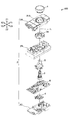
- the disassembled perspective view of the input device of FIG. FIG. 2 is an exploded perspective view of a housing of the input device shown in FIG. 1.
- the perspective view of the 1st support member of the input device of FIG. The perspective view of the 1st detection member of the input device of FIG.
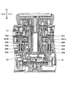
- the perspective view of the 2nd detection member of the input device of FIG. FIG. 2 is a sectional view of the input device of FIG. 1 taken along the line AA.
- FIG. 3 is a perspective view of a restriction member of the input device of FIG. 1.
- FIG. 2 is a sectional view of the input device of FIG. 1 taken along the line BB.
- the perspective view which removed the knob and the housing from the input device of FIG. The perspective view which removed the knob and the upper housing from the input device of FIG.
- the input device 100 is an input device that can change the type of operation of the knob 1 that can be performed by exchanging one component (regulating member 7).
- regulating member 7 There are two types of regulating members 7, which are referred to as regulating members 7A and 7B, respectively.
- the input device 100 can be used, for example, as an input device of a product in which the operation of the knob 1 is used. Products in which operation of the knob 1 is utilized include, but are not limited to, vehicles and game controllers.
- the input device 100 can operate the operation knob 1 of two or more kinds of knobs 1 including the first operation and the second operation.
- the first operation is an operation that does not involve horizontal movement of the knob 1.
- the first operation includes, but is not limited to, a rotating operation, a pressing operation, and a touch operation.
- the second operation is an operation that involves horizontal movement of the knob 1.
- the second operation includes, but is not limited to, a tilt operation and a slide operation.
- the input device 100 may be capable of performing only the first operation and the second operation, or in addition to the first operation and the second operation, one type that is different from the first operation and does not involve horizontal movement of the knob 1. The above operations may be possible.
- the input device 100 can regulate the second operation by exchanging the regulation member 7.
- the input device 100 can be used as an input device that cannot perform the second operation of the knob 1 by attaching the regulation member 7A as the regulation member 7, and the input that allows the second operation of the knob 1 by attaching the regulation member 7B as the regulation member 7. It can be used as a device. That is, the input device 100 can change the type of operation of the knob 1 that can be input by exchanging the restriction member 7.
- the input device 100 in which the first operation is a rotation operation, the second operation is a tilt operation, and the third operation is a pressing operation will be described.
- the first operation may be a pressing operation or a touch operation
- the second operation may be a slide operation
- the third operation may be a rotating operation or a touch operation. ..
- FIG. 1 is an external perspective view showing an example of the input device 100.
- FIG. 2 is an exploded perspective view of the input device 100 of FIG.
- FIG. 3 is an exploded perspective view of the housing 2 of the input device 100 of FIG.
- FIG. 4 is a perspective view of the input device 100 shown in FIG.
- FIG. 5 is a perspective view of the first support member 3 of the input device 100 of FIG.
- FIG. 6 is a perspective view of the first detection member 4 of the input device 100 of FIG.
- FIG. 7 is a perspective view of the second support member 5 of the input device 100 of FIG.
- FIG. 8 is a perspective view of the second detection member 6 of the input device 100 of FIG.
- FIG. 9 is a cross-sectional view of the input device 100 of FIG. 1 taken along the line AA.
- the line AA is a straight line passing through the centers of the actuators 65A and 65B.
- FIG. 10 is a perspective view of the cam member 66 of the input device 100 of FIG. 1 as viewed from below.
- FIG. 11 is a perspective view of the restriction member 7A of the input device 100 of FIG.
- FIG. 12 is a perspective view showing an example of the regulation member 7B.
- FIG. 13 is a cross-sectional view of the input device 100 of FIG. 1 taken along the line BB.
- the line BB is a straight line that passes through the virtual central axis L and extends in the Y direction.
- FIG. 14 is a perspective view of the input device 100 of FIG. 1 with the knob 1 and the housing 2 removed.
- FIG. 15 is a perspective view of the input device 100 of FIG.
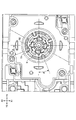
- FIG. 16 is a top view of the input device 100 of FIG. 1 with the knob 1 and the upper housing 2A removed.
- FIG. 17 is a top view of the input device 100 including the regulation member 7B (a modified example of the input device 100 of FIG. 1) from which the knob 1 and the upper housing 2A are removed.
- the input device 100 will be described with reference to the directions shown in the figure (X1, X2, Y1, Y2, Z1, Z2 directions).
- the X1 and X2 directions are collectively referred to as the X direction
- the Y1 and Y2 directions are collectively referred to as the Y direction
- the Z1 and Z2 directions are collectively referred to as the Z direction.
- the X, Y and Z directions are orthogonal to each other.
- the Z1 direction and the Z2 direction may be referred to as the upper side and the lower side, respectively.
- the input device 100 includes a knob 1, a housing 2, a first support member 3, a first detection member 4, a second support member 5, a second detection member 6, and a regulation member. And a member 7A.
- the knob 1 is a member operated by the user.
- the knob 1 of FIG. 1 has a substantially columnar shape, and the lower surface is fixed to the first support member 3 (see FIG. 13).
- the knob 1 is supported by the first support member 3 so as to be exposed to the outside along a virtual center axis L that extends in the Z direction through the opening 21A of the housing 2 (see FIGS. 1 and 2).
- the knob 1 can be rotated (first operation), tilted (second operation), and pressed (third operation).
- the rotation operation of the knob 1 is an operation of rotating the knob 1 rotatably supported by the first support member 3 in the XY plane about the virtual central axis L.
- the tilt operation of the knob 1 is an operation of tilting the knob 1 in at least one of the X direction and the Y direction, which is a direction intersecting the virtual central axis L.
- the pressing operation of the knob 1 is an operation of moving the knob 1 supported by the first support member 3 in a direction parallel to the virtual central axis L (Z2 direction).
- the knob 1 moves horizontally when the tilt operation is performed, but does not move horizontally even when the rotation operation and the pressing operation are performed.
- the horizontal movement here is movement in the XY plane, that is, movement in at least one of the X direction and the Y direction.
- knob 1 is not limited to the example shown in the figure.
- the knob 1 can have any shape that can be operated by the user.
- the housing 2 is a member that houses the first support member 3, the first detection member 4, the second support member 5, the second detection member 6, and the regulation member 7. As shown in FIG. 3, the housing 2 includes an upper housing 2A, a middle housing 2B, and a lower housing 2C.
- the upper housing 2A is a member that constitutes the upper part of the housing 2.
- the upper housing 2A is fixed to the upper side of the middle housing 2B.
- the upper housing 2A has an opening 21A, a plurality of push buttons 22A, and a plurality of pressing portions 23A.
- the opening 21A is an opening formed on the upper surface of the upper housing 2A for inserting the knob 1, the first supporting member 3, and the second supporting member 5.
- the opening 21A is formed wider than the movement range of the outer peripheral portion of the knob 1 so that the knob 1 can be tilted (see FIG. 13).
- the push button 22A is a push button arranged on the upper surface of the upper housing 2A.
- the push button 22A is arranged so as to be exposed on the upper surface of the upper housing 2A.
- the shape and number of the push buttons 22A are not limited to the example of FIG.
- the upper housing 2A may not include the push button 22A.
- the pressing portion 23A is a portion extending downward from the lower surface of the push button 22A.
- the pressing portion 23A is provided on the lower surface of the push button 22A.
- the lower end of the pressing portion 23A is in contact with the upper side of the dome portion 621, and the dome portion 621 is directly or indirectly pressed by the pressing operation of the push button 22A (see FIG. 13).
- the dome portion 621 will be described later.
- the middle casing 2B is a member that constitutes the central portion of the casing 2 in the Z direction.
- the middle case 2B is fixed to the lower side of the upper case 2A and is fixed to the upper side of the lower case 2C. Further, a part of the components of the second detection member 6 and the regulation member 7 are attached to the upper surface side of the middle housing 2B.
- the middle housing 2B has an opening 21B, storages 22B and 23B, and a through hole 24B.
- the opening 21B is an opening formed on the upper surface of the middle housing 2B for inserting the knob 1, the first supporting member 3, and the second supporting member 5.
- the opening 21B is formed wider than the movement range of the outer peripheral portions of the knob 1, the first support member 3, and the second support member 5 so that the knob 1 can be tilted (see FIG. 13).
- the storage portions 22B and 23B are concave portions that protrude downward from the upper surface of the middle housing 2B (convex shape in FIG. 4).
- the storages 22B and 23B are formed around the opening 21B.
- Coil springs 64A and 64B and actuators 65A and 65B are stored in the storage portions 22B and 23B, respectively (see FIG. 9). The coil springs 64A and 64B and the actuators 65A and 65B will be described later.
- the through hole 24B is a through hole formed between the upper surface and the lower surface of the middle housing 2B for inserting the upper end of the pressing member 67 (see FIG. 8).
- the through hole 24B is formed in a region close to the opening 21B.
- the pressing member 67 will be described later.
- the lower housing 2C is a member that constitutes the lower part of the housing 2.
- the lower housing 2C is fixed to the lower side of the middle housing 2B.
- the components of the first detection member 4 and the second detection member 6 are held between the lower surface of the middle housing 2B and the upper surface of the lower housing 2C.
- a recess 21C that supports the fulcrum portion 53 (see FIG. 13) of the second support member 5 is provided on the upper surface of the lower housing 2C.
- the configuration of the housing 2 is not limited to the example shown in the figure.
- the housing 2 may have any configuration capable of accommodating the first support member 3, the first detection member 4, the second support member 5, the second detection member 6, and the regulation member 7.
- the first support member 3 is a member that supports the knob 1 so that the knob 1 can be rotated (first operation) and pressed (third operation).
- the first support member 3 has a substantially shaft shape extending in a direction (Z direction) parallel to the virtual center axis L, and includes a shaft member 31, a bearing member 32, and a pressing member 33 (FIGS. 5 and 13 ). reference).
- the shaft member 31 is a substantially cylindrical member extending in a direction (Z direction) parallel to the virtual central axis L.
- the shaft member 31 is rotatably supported by the bearing member 32, and is arranged in contact with the upper side of the pressing member 33 (see FIGS. 9 and 13).
- the lower surface of the knob 1 is fixed to the upper end of the shaft member 31 with a bolt B.
- the knob 1 When the knob 1 is rotationally operated, the shaft member 31 rotates around the virtual central axis L together with the knob 1.
- the shaft member 31 tilts together with the knob 1 in a direction intersecting the virtual center axis L.
- the shaft member 31 moves together with the knob 1 in the direction parallel to the virtual center axis L.
- the direction parallel to the virtual center axis L coincides with the Z direction when the knob 1 is not tilted.
- the shaft member 31 has a light shielding portion 311 at the lower end.
- the light shielding portion 311 is a dome-shaped portion that spreads outward from the lower end of the shaft member 31 toward the outside. Substantially rectangular convex portions 312 are formed at equal intervals on the lower end of the light shielding portion 311.
- the light shielding unit 311 constitutes a part of an optical rotation sensor (rotation detection circuit). As will be described later, when the light blocking portion 311 rotates together with the knob 1, the first detection member 4 can detect the rotation of the knob 1.
- the bearing member 32 is a tubular member that supports the shaft member 31 so as to be rotatable about the virtual central axis L and movable in a direction parallel to the virtual central axis L.
- the bearing member 32 is fixed to the second support member 5, and the shaft member 31 is inserted inside. That is, the bearing member 32 is arranged between the shaft member 31 and the second support member 5 (see FIG. 13).
- the bearing member 32 functions as a bearing that suppresses the influence of the shaft member 31 that rotates and moves inside thereof from affecting the second support member 5.
- the pressing member 33 is a member that supports the shaft member 31 from below. As shown in FIG. 13, the pressing member 33 is arranged below the shaft member 31 and is arranged in contact with the upper side of the dome portion 421. When the knob 1 is pressed, the shaft member 31 descends in a direction parallel to the virtual center axis L, and the dome portion 421 is pressed via the pressing member 33. The dome portion 421 will be described later.
- the configuration of the first support member 3 is not limited to the example shown in the figure.
- the first support member 3 may not include the bearing member 32, and the shaft member 31 and the pressing member 33 may be integrally formed.
- the first support member 3 may have any configuration capable of supporting the knob 1 so that the knob 1 can be rotated and pressed.
- the first detection member 4 is a member that detects a rotating operation and a pressing operation (one example of each of the “first operation” and the “third operation”) of the knob 1.
- the first detection member 4 is arranged below the first support member 3 and is fixed to the lower housing 2C.
- the first detection member 4 includes a circuit board 41, a sheet member 42, and connection terminals 43 (see FIG. 6).
- the circuit board 41 is a board on which a rotation detecting circuit for detecting a rotating operation of the knob 1 and a pressing detecting circuit for detecting a pressing operation of the knob 1 are mounted.
- the circuit board 41 may be a rigid board or a flexible board.
- the rotation detection circuit is an optical type and has a transmissive optical sensor 44 that integrally includes an LED (Light Emitting Diode) and a light receiving element.
- This rotation detection circuit receives the reflected light of the light emitted by the LED by the light receiving element.
- the rotation speed (rotation angle) of the knob 1 can be calculated based on the change in the output waveform of the light receiving element.
- the pressing detection circuit includes a plurality of fixed contacts that are spaced apart from each other, and a detection circuit that detects conduction of the fixed contacts.
- the pressure detection circuit will be described later.
- the sheet member 42 is a sheet formed of an elastic member such as silicon rubber, and is arranged so as to cover the upper surface of the circuit board 41.
- the sheet member 42 functions as a dustproof sheet and a waterproof sheet of the circuit board 41.
- the sheet member 42 has three dome portions 421.
- the dome portion 421 is a dome-shaped portion that projects upward from the upper surface of the sheet member 42.
- the dome portions 421 are evenly arranged below the pressing member 33 so that the pressing member 33 can be stably supported.
- the dome portion 421 is formed so as to cover the plurality of fixed contacts.
- the movable contact is fixed to the lower surface of the dome portion 421 so as to cover the plurality of fixed contacts.
- the dome portion 421 is pressed via the pressing member 33.
- the dome portion 421 buckles when pressed with a predetermined force or more, and the lower surface thereof contacts the surface of the circuit board 41.
- the movable contact fixed to the lower surface of the dome portion 421 and a plurality of fixed contacts arranged below the dome portion 421 come into contact with each other, and Conducts.
- the pressing operation of the knob 1 can be detected by detecting the conduction by the detection circuit.
- the pressing operation of the knob 1 is completed (the user releases the finger from the knob 1)
- the shape of the dome portion 421 is restored by the elastic force of the sheet member 42.
- the first support member 3 is pushed up and returns to its original position.
- the knob 1 returns to the original position (initial position).
- the connection terminal 43 is a terminal for connecting the circuit board 41 and the circuit board 61.
- the output signal of the circuit board 41 (the detection result of the rotation operation and the pressing operation) is output to the external device of the input device 100 via the circuit board 61.
- the circuit board 61 will be described later.
- the configuration of the first detection member 4 is not limited to the example shown in the figure.
- the rotation detection circuit may be magnetic or photoelectric.
- the pressure detection circuit may be configured by a disc spring or the like.
- the sheet member 42 may have one, two, or four or more dome portions 421.
- the first detection member 4 can have any configuration capable of detecting the rotation operation and the pressing operation of the knob 1.
- the second support member 5 is a tubular member that supports the first support member 3 so that the knob 1 can be tilted.
- the second support member 5 has the first support member 3 inserted therein, and the inner peripheral surface thereof is fixed to the bearing member 32.
- the first support member 3 tilts, and the second support member 5 fixed to the bearing member 32 tilts together with the first support member 3.
- the second support member 5 is also connected to the annular member 63.
- the annular member 63 will be described later.
- the second support member 5 has four convex portions 51, four groove portions 52, and a fulcrum portion 53.
- the convex portion 51 is a substantially cylindrical member that extends outward from the outer peripheral surface of the second support member 5.
- the convex portion 51 is inserted with a degree of freedom in the Z direction into the connecting groove 634 provided in the annular member 63.
- the four convex portions 51 are arranged at equal intervals on the outer peripheral surface of the second support member 5.
- the second support member 5 is tilted, and the convex portion 51 moves in the Z direction inside the connection groove 634 provided in the annular member 63 while the connection groove 634 of the connection groove 634 is formed.
- the tilting motion of the second support member 5 is converted into the sliding motion of the annular member 63 in the horizontal direction.
- the number of convex portions 51 is not limited to the example shown in the figure.
- the connection structure of the second support member 5 and the annular member 63 when the knob 1 is slid in the horizontal direction (XY plane direction) is different from the connection structure of the protrusion 51 in the connection groove 634 in the Z direction. Similar to the above-described tilt operation, the annular member 63 slides in the same direction as the sliding operation by the sliding operation of the knob 1.
- the groove 52 is a groove formed on the outer peripheral surface of the second support member 5 and extending in a direction parallel to the virtual central axis L (Z direction).
- the groove 52 is fitted with a rib 73 extending in a direction (Z direction) parallel to the virtual central axis L of the regulating member 7A (see FIGS. 11 and 16).
- the four groove portions 52 are formed at equal intervals on the outer peripheral surface around the virtual center axis L of the second support member 5.
- the groove portion 52 is provided at a position that forms a predetermined angle ⁇ (for example, ⁇ is about 15 to 25 degrees in the present embodiment) with respect to the tilt operation direction (X direction and Y direction) of the knob 1. Accordingly, when a horizontal load is applied to the second support member 5, the load is distributed to the plurality of groove portions 52, so that damage to the groove portions 52 can be suppressed.
- the number of grooves 52 and the angles at which they are arranged are not limited to the example shown in the figure.
- the fulcrum portion 53 is a projecting portion provided on the lower end of the second support member 5, as shown in FIG.
- the fulcrum portion 53 is supported by the recess 21C provided on the upper surface of the lower housing 2C, and functions as a tilt fulcrum of the second support member 5. That is, the second support member 5 tilts with the support portion 53 as a fulcrum.
- the configuration of the second support member 5 is not limited to the example shown in the figure.
- the second support member 5 may have any configuration capable of supporting the first support member 3 such that the knob 1 can be tilted.
- the second detection member 6 is a member that detects a tilt operation of the knob 1 (an example of “second operation”). In the second detection member 6, some of the components are held between the upper surface of the middle casing 2B and the regulating member 7, and the other components are formed between the lower surface of the middle casing 2B and the upper surface of the lower casing 2C. Held in between. As shown in FIGS. 8 to 10, the second detection member 6 includes a circuit board 61, a sheet member 62, an annular member 63, coil springs 64A and 64B, actuators 65A and 65B, and cam members 66A and 66B. And a pressing member 67.
- the circuit board 61 is a board on which a tilt detection circuit for detecting the tilt operation of the knob 1 is mounted.
- the circuit board 61 may be a rigid board or a flexible board.
- the lower surface of the circuit board 61 is provided with output terminals for outputting the output signals of the circuit boards 41 and 61 to an external device.
- the tilt detection circuit includes a plurality of fixed contacts that are spaced apart from each other, and a detection circuit that detects conduction of the fixed contacts.
- the tilt detection circuit will be described later.
- the sheet member 62 is a sheet formed of an elastic member such as silicon rubber, and is arranged so as to cover the upper surface of the circuit board 61.
- the sheet member 62 functions as a dustproof sheet and a waterproof sheet of the circuit board 61.
- the sheet member 62 has a plurality of dome portions 621 and four dome portions 622.
- the dome portion 621 is a dome-shaped portion protruding upward from the upper surface of the sheet member 62.
- the plurality of dome portions 621 are arranged in contact with the lower sides of the plurality of pressing portions 23A that are inserted into through holes (not shown) provided in the middle housing 2B.
- the dome portion 621 is formed so as to cover the plurality of fixed contacts.
- the movable contact is fixed to the lower surface of the dome portion 621 so as to cover the plurality of fixed contacts.
- the dome portion 621 When the push button 22A is pushed, the dome portion 621 is pushed via the pushing portion 23A provided on the lower surface of the push button 22A.
- the dome portion 621 buckles when pressed with a predetermined force or more, and the lower surface thereof contacts the surface of the circuit board 61.
- the movable contact fixed to the lower surface of the dome portion 621 and a plurality of fixed contacts arranged below the dome portion 621 come into contact with each other. Conducts.
- the pressing operation of the push button 22A can be detected.
- the push button 22A when the push operation of the push button 22A is completed (the user releases the push button 22A), the shape of the dome portion 621 is restored by the elastic force of the sheet member 62. As a result, the push button 22A is pushed up and returns to its original position.
- the dome portion 622 is a dome-shaped portion that protrudes upward from the upper surface of the sheet member 62. All of the four dome portions 622 are arranged in contact with the lower side of the pressing member 67. The four dome portions 622 are arranged at equal intervals in the operation direction (X1, X2, Y1, Y2 side) of the knob 1 with respect to the central portion of the pressing member 67 so that the pressing member 67 can be stably supported. Will be placed.
- the dome portion 622 is formed so as to cover the plurality of fixed contacts.
- the movable contact is fixed to the lower surface of the dome portion 622 so as to cover the plurality of fixed contacts. The operation of the dome portion 622 will be described later.
- the annular member 63 is an annular member that converts the tilt operation of the knob 1 into a horizontal sliding operation.
- the annular member 63 is arranged so as to surround the outer peripheral surface of the second support member 5, and is connected to the second support member 5.
- the annular member 63 moves horizontally while the height in the Z direction (position movable in the direction parallel to the virtual center axis L) is restricted by the upper surface of the middle housing 2B and the lower surface of the restriction member 7. Retained as possible.
- the annular member 63 has cam fixing portions 631 and 632, a pressing portion 633, and a connecting groove 634.
- the cam fixing portions 631 and 632 are portions that protrude outward from the outer peripheral portion of the annular member 63, and are formed at positions facing each other with the virtual central axis L in between.
- the cam fixing portions 631 and 632 have the cam members 66A and 66B fixed to the lower surfaces thereof, respectively.
- the cam members 66 having the same shape are arranged at opposite positions with good balance, but the annular member 63 may have three or more cam fixing portions, or may have one.
- the pressing unit 633 will be described later.
- connection groove 634 is a groove formed in the inner peripheral surface of the annular member 63 and extending in the Z direction.
- the connection groove 634 is connected to the protrusion 51 so that the protrusion 51 of the second support member 5 can move in the Z direction.
- the coil springs 64A and 64B are elastic members that are housed in the housing parts 22B and 23B of the middle housing 2B, respectively, inserted through the actuators 65A and 65B, and supported in a state of extending in the Z direction. ..
- the coil springs 64A and 64B have their lower ends abutted on the bottom surfaces of the storage portions 22B and 23B, and their upper ends abutted on the lower surfaces of the abutting portions of the actuators 65A and 65B, and urge the actuators 65A and 65B upward.
- the actuators 65A and 65B are rod-shaped members that are housed in the housing portions 22B and 23B of the middle housing 2B and inserted into the coil springs 64A and 64B, and that extend in the Z direction.
- the actuator 65 has an abutting portion formed thicker than the coil spring 64 on the upper portion, and the lower surface of the abutting portion abuts the upper end of the coil spring 64.
- the actuator 65 is biased upward by the coil spring 64.
- the cam members 66A and 66B are members having cam surfaces 661A and 661B on their lower surfaces, and are fixed to the lower surfaces of the cam fixing portions 631 and 632.
- the upper end of the actuator 65 contacts the cam surface 661 of the cam member 66 while being pressed by the bias of the coil spring 64.
- the cam surface 661 is formed in a cross shape. More specifically, the cam surface 661 has a concave portion 662 formed in the central portion and a guide curved surface 663 inclined from the concave portion 662 in the tilt operation direction (X direction and Y direction).
- the recess 662 corresponds to the initial position of the knob 1, and contacts the upper end of the actuator 65 while the knob 1 is in the initial position.
- the cam surface 661 tilts as the annular member 63 tilts, and the guide curved surface 663 and the upper end of the actuator 65 come into contact with each other.
- the load on the cam member 66 from the actuator 65 varies, and a click feeling occurs.
- the knob 1 (cam member 66) is automatically moved at the end of the tilt operation. Can be returned to the initial position.
- the pressing member 67 is a disk-shaped member that selectively presses the dome portion 622 of the sheet member 62.
- the pressing member 67 is arranged in contact with the upper sides of the four dome portions 622, and is arranged below the tip of the pressing portion 633 of the annular member 63. Further, the pressing member 67 is inserted into the through hole 24B of the middle housing 2B and is swingably supported near the lower outlet of the through hole 24B, and is tilted with respect to the respective directions of the four dome portions 622. It is possible.
- the pressing portion 633 is a portion that projects outward from the outer peripheral portion of the annular member 63, and the tip portion extends downward.
- the tip portion of the pressing portion 633 is arranged so as to surround the upper end portion of the pressing member 67, presses the upper end portion of the pressing member 67 during movement, and tilts the pressing member 67 in the moving direction.
- the height of the annular member 63 is restricted by the restricting member 7, so that the annular member 63 slides in the tilting direction together with the second supporting member 5.
- the tip of the pressing portion 633 moves in the operating direction of the knob 1
- the operating direction side of the pressing member 67 is pressed, and the pressing member 67 tilts toward the dome portion 622 arranged on the operating direction side with the central portion of the pressing member 67 as a fulcrum.
- the dome portion 622 arranged on the operation direction side is pressed downward.
- the dome portion 622 buckles when pressed with a predetermined force or more, and the surface of the dome shape facing the circuit board 61 contacts the surface of the circuit board 61.
- the facing surface of the dome portion 622 comes into contact with the surface of the circuit board 61
- the movable contact fixed to the facing surface of the dome portion 622 and a plurality of fixed contacts arranged on the surface of the circuit board 61 come into contact with each other and are fixed. There is continuity between the contacts.
- the tilt operation of the knob 1 in the operation direction can be detected by detecting the conduction by the detection circuit.
- the shape of the dome portion 622 is restored by the elastic force of the sheet member 62.
- the pressing member 67 is pushed up by the restoring force of the shape of the dome portion 622.
- the annular member 63 is pressed together with the cam member 66 in the direction along the cam surface 661 by the elastic force of the coil spring 64 against the actuator 65 that is in contact with the cam member 66. As a result, the annular member 63 returns to its original position, and the knob 1 returns to its original position.
- the configuration of the second detection member 6 is not limited to the example shown in the figure.
- the tilt detection circuit may be configured by a disc spring or the like.
- the second detection member 6 may be biased by one or three or more coil springs 64.
- the sheet member 62 may have two or more sets of four dome portions 622 for detecting the tilt operation of the knob 1, and the four dome portions 622 are pressed by different pressing members 67. Good.
- the second detection member 6 can have any configuration capable of detecting the tilt operation of the knob 1.
- the restriction member 7 is a member that restricts the movement of the second detection member 6 in the direction parallel to the virtual central axis L (Z direction). As shown in FIG. 15, the restriction member 7 is detachably attached to the middle housing 2B with a bolt B.
- the regulating member 7 is arranged on the upper side of the annular member 63, which is a component of the second detection member 6, and holds the annular member 63 between the lower surface of the annular member 63 and the upper surface of the middle housing 2B. Restrict movement in the Z direction. This enables stable movement of the annular member 63 in the sliding direction (the direction intersecting with the virtual central axis L).
- the regulation member 7 includes a regulation member 7A and a regulation member 7B.
- the regulation member 7A is a regulation member 7 that regulates the tilt of the second support member 5
- the regulation member 7B is a regulation member 7 that does not regulate the tilt of the second support member 5.
- the regulation member 7A has a plate-shaped portion 71, an annular portion 72, and four ribs 73.
- the plate-like portion 71 is a flat plate-like portion, and has attachment portions 71A having through holes (not shown) through which the bolts B are inserted at four corners, and is attached to the upper surface of the middle housing 2B by the bolts B.
- the upper surface of the annular member 63 biased upward by the coil spring 64 is pressed against the lower surface of the plate-shaped portion 71.
- the plate-shaped portion 71 has an opening 711 in the center thereof for inserting the second support member 5.
- the annular portion 72 is an annular portion that surrounds the opening 711 formed in the plate-shaped portion 71. Ribs 73 are formed on the inner peripheral surface of the annular portion 72.
- the rib 73 is a portion that protrudes inward from the inner peripheral surface of the annular portion 72 and extends in the Z direction.
- the ribs 73 are fitted into the groove portions 52 of the second support member 5 by inserting the ribs 73 from the top to the bottom when the regulation member 7A is attached to the middle housing B2, and regulate the tilt of the second support member 5. ..
- the four ribs 73 are formed at positions corresponding to the groove portions 52 of the second support member 5, respectively. Further, the rib 73 is provided at a position forming a predetermined angle ⁇ with respect to the operation direction of the knob 1 (X direction and Y direction).
- the configuration of the regulation member 7A is not limited to the example shown in the figure.
- the regulating member 7A when the regulating member 7A can form the rib 73 on the inner peripheral surface of the opening 711, the regulating member 7A does not have to have the annular portion 72.
- the number of ribs 73 is not limited to the example shown in the figure.
- the method of attaching the regulation member 7 to the middle housing 2B is not limited to the bolt B.
- the restricting member 7A may have any configuration that restricts the movement of the second detection member 6 in the direction parallel to the virtual center axis L and allows the movement in the direction intersecting the virtual center axis L.
- the input device 100 is an input device capable of rotating and pressing the knob 1.
- the rib 73 is provided at a position forming a predetermined angle ⁇ with respect to the operating direction of the knob 1 (X direction and Y direction).
- the regulating member 7B has a plate-shaped portion 71 and an annular portion 72. That is, the configuration of the regulation member 7B is the same as that of the regulation member 7A except that the rib 73 is not provided.
- the input device 100 is an input device capable of rotating, tilting, and pressing the knob 1.
- the input device 100 can rotate and push the knob 1 when the regulating member 7A is attached, and can rotate the knob 1 when the regulating member 7B is attached. Tilt operation and push operation are possible. That is, by exchanging the restricting member 7, it is possible to change whether or not the tilt operation of the knob 1 in the input device 100 can be performed. Further, since the regulating member 7 is detachably attached to the middle housing 2B, it can be easily replaced. Therefore, the input device 100 can easily change the type of operation of the knob 1 that can be performed (whether or not the tilt operation is possible).
- the configurations of the regulating members 7A and 7B are the same except for the presence or absence of the rib 73. Therefore, the two types of regulating members 7 can be easily designed and manufactured. As a result, the design cost of the input device 100 can be reduced. Also, the same equipment can be used in the assembly process, and the equipment investment can be reduced.
- the fulcrum portion 53 is provided at the lower end of the second support member 5, and the housing 2 supports the fulcrum portion 53 to enable the tilt operation of the second support member 5, but the fulcrum portion 53 is eliminated. Then, the entire second support member 5 may be supported by the housing 2 so as to be slidable.
- Knob 2 Housing 2A: Upper housing 2B: Middle housing 2C: Lower housing 3: First support member 4: First detection member 5: Second support member 6: Second detection member 7: Restriction member 21A and 21B: Opening 31: Shaft member 32: Bearing member 33: Pressing member 41: Circuit board 42: Sheet member 43: Connection terminal 51: Convex portion 52: Groove portion 53: Support point portion 61: Circuit board 62: Sheet member 63 : Annular members 64A, 64B: coil springs 65A, 65B: actuators 66A, 66B: cam members 67: pressing members 71: plate-like parts 72: annular parts 73: ribs 100: input device L: virtual central axis ⁇ : predetermined angle
Landscapes
- Switches With Compound Operations (AREA)
- Position Input By Displaying (AREA)
Abstract
可能なノブ1の操作の種類を容易に変更できる入力装置を提供する。 一実施形態に係る入力装置は、開口部を有する筐体と、前記筐体の前記開口部を通る仮想中心軸に沿って外部に露出され、ユーザにより操作されるノブと、前記ノブを第1操作が可能なように支持する第1支持部材と、前記第1支持部材を、前記ノブの第2操作が可能なように支持する第2支持部材と、前記第1操作を検出する第1検出部材と、前記第2操作を検出する第2検出部材と、前記第2検出部材の移動を規制する、前記筐体に対して着脱可能な規制部材と、を備え、前記第2支持部材は、外周面に、前記仮想中心軸と平行な方向に延びる溝部を有し、ユーザによる前記第2操作を不可とする場合には、前記溝部に嵌合するリブを有する前記規制部材が取り付けられ、ユーザによる前記第2操作を可能とする場合には、前記溝部に嵌合するリブを有しない前記規制部材が取り付けられる。
Description
本発明は、入力装置に関する。
従来、ノブの回転操作が可能な入力装置が知られている。また、チルト操作や回転操作などの、複数種類のノブ1の操作が可能な入力装置も知られている。
従来の入力装置は、可能なノブ1の操作の種類に応じてそれぞれ設計されていた。このため、例えば、3種類のノブ1の操作が可能な入力装置を、2種類のノブ1の操作が可能な入力装置として利用することができなかった。この結果、製品ラインナップとして、3種類のノブ1の操作が可能な入力装置を備えた製品と、2種類のノブ1の操作が可能な入力装置を備えた製品と、を用意する場合、2種類の入力装置をそれぞれ設計しなければならず、設計工数が多くなるという問題があった。
本発明は、上記の課題に鑑みてなされたものであり、可能なノブ1の操作の種類を容易に変更できる入力装置を提供することを目的とする。
一実施形態に係る入力装置は、開口部を有する筐体と、前記筐体の前記開口部を通る仮想中心軸に沿って外部に露出され、ユーザにより操作されるノブと、前記ノブを第1操作が可能なように支持する第1支持部材と、前記第1支持部材を、前記ノブの第2操作が可能なように支持する第2支持部材と、前記第1操作を検出する第1検出部材と、前記第2操作を検出する第2検出部材と、前記第2検出部材の移動を規制する、前記筐体に対して着脱可能な規制部材と、を備え、ユーザによる前記第2操作を不可とする場合には、前記溝部に嵌合するリブを有する前記規制部材が取り付けられ、ユーザによる前記第2操作を可能とする場合には、前記溝部に嵌合するリブを有しない前記規制部材が取り付けられる。
本発明の各実施形態によれば、可能なノブ1の操作の種類を容易に変更できる入力装置を提供できる。
以下、本発明の各実施形態について、添付の図面を参照しながら説明する。なお、各実施形態に係る明細書及び図面の記載に関して、実質的に同一の機能構成を有する構成要素については、同一の符号を付することにより重畳した説明を省略する。
一実施形態に係る入力装置100について、図1~図17を参照して説明する。入力装置100は、1つの部品(規制部材7)を交換することにより、可能なノブ1の操作の種類を変更できる入力装置である。規制部材7は2種類あり、それぞれ規制部材7A,7Bと称す。入力装置100は、例えば、ノブ1の操作が利用される製品の入力装置として利用できる。ノブ1の操作が利用される製品は、車両及びゲームコントローラを含むが、これに限られない。
入力装置100は、第1操作及び第2操作を含む2種類以上のノブ1の操作ノブ1の操作が可能である。第1操作は、ノブ1の水平移動を伴わない操作である。第1操作は、回転操作、押圧操作、及びタッチ操作を含むが、これに限られない。第2操作は、ノブ1の水平移動を伴う操作である。第2操作は、チルト操作及びスライド操作を含むが、これに限られない。入力装置100は、第1操作及び第2操作のみが可能であってもよいし、第1操作及び第2操作に加えて、第1操作とは異なる、ノブ1の水平移動を伴わない1種類以上の操作が可能であってもよい。
また、入力装置100は、規制部材7の交換により、第2操作の規制が可能である。入力装置100は、規制部材7として規制部材7Aを取り付けることにより、ノブ1を第2操作できない入力装置として利用でき、規制部材7として規制部材7Bを取り付けることにより、ノブ1を第2操作できる入力装置として利用できる。すなわち、入力装置100は、規制部材7の交換により、入力可能なノブ1の操作の種類を変更することができる。
以下、一例として本実施形態では、第1操作が回転操作、第2操作がチルト操作、第3操作が押圧操作である入力装置100について説明する。なお、本実施形態において、第1操作は押圧操作又はタッチ操作であってもよいし、第2操作はスライド操作であってもよいし、第3操作は回転操作又はタッチ操作であってもよい。
図1は、入力装置100の一例を示す外観斜視図である。図2は、図1の入力装置100の分解斜視図である。図3は、図1の入力装置100の筐体2の分解斜視図である。図4は、図1の入力装置100の中筐体2Bの下側から見た斜視図である。図5は、図1の入力装置100の第1支持部材3の斜視図である。図6は、図1の入力装置100の第1検出部材4の斜視図である。図7は、図1の入力装置100の第2支持部材5の斜視図である。図8は、図1の入力装置100の第2検出部材6の斜視図である。図9は、図1の入力装置100のA-A線断面図である。A-A線は、アクチュエータ65A,65Bの中心を通る直線である。図10は、図1の入力装置100のカム部材66を下側から見た斜視図である。図11は、図1の入力装置100の規制部材7Aの斜視図である。図12は、規制部材7Bの一例を示す斜視図である。図13は、図1の入力装置100のB-B線断面図である。B-B線は、仮想中心軸Lを通りY方向に延びる直線である。図14は、図1の入力装置100からノブ1及び筐体2を除いた斜視図である。図15は、図1の入力装置100からノブ1及び上筐体2Aを除いた斜視図である。図16は、図1の入力装置100からノブ1及び上筐体2Aを除いた上面図である。図17は、規制部材7Bを備えた入力装置100(図1の入力装置100の変形例)からノブ1及び上筐体2Aを除いた上面図である。
以下、入力装置100について図に示す方向(X1,X2,Y1,Y2,Z1,Z2方向)を基準として説明する。X1,X2方向をX方向、Y1,Y2方向をY方向、Z1,Z2方向をZ方向と総称する。X,Y,Z方向は互いに直交する。また、Z1方向及びZ2方向をそれぞれ上方及び下方と称する場合がある。
入力装置100は、図2に示すように、ノブ1と、筐体2と、第1支持部材3と、第1検出部材4と、第2支持部材5と、第2検出部材6と、規制部材7Aと、を備える。
ノブ1は、ユーザにより操作される部材である。図1のノブ1は、略円柱形状を有し、下面を第1支持部材3に固定される(図13参照)。ノブ1は、筐体2の開口部21Aを通りZ方向に延びる仮想中心軸Lに沿って外部に露出するように、第1支持部材3により支持される(図1及び図2参照)。
上述の通り、ノブ1の操作として、回転操作(第1操作)、チルト操作(第2操作)、及び押圧操作(第3操作)が可能である。ノブ1の回転操作は、第1支持部材3に回転可能に支持されたノブ1を、仮想中心軸Lを中心としてXY平面内で回転させる操作である。ノブ1のチルト操作は、ノブ1を仮想中心軸Lと交差する方向であるX方向及びY方向の少なくとも一方に傾倒させる操作である。ノブ1の押圧操作は、第1支持部材3に支持されたノブ1を仮想中心軸Lに平行な方向(Z2方向)に移動させる操作である。ノブ1は、チルト操作を行うと水平移動するが、回転操作及び押圧操作を行っても水平移動しない。ここでいう水平移動とは、XY平面内の移動、すなわち、X方向及びY方向の少なくとも一方への移動のことである。
なお、ノブ1の構成は、図の例に限られない。ノブ1は、ユーザが操作可能な任意の形状とすることができる。
筐体2は、第1支持部材3、第1検出部材4、第2支持部材5、第2検出部材6、及び規制部材7を収納する部材である。図3に示すように、筐体2は、上筐体2Aと、中筐体2Bと、下筐体2Cと、を備える。
上筐体2Aは、筐体2の上部を構成する部材である。上筐体2Aは、中筐体2Bの上側に固定される。上筐体2Aは、開口部21Aと、複数の押ボタン22Aと、複数の押圧部23Aと、を有する。
開口部21Aは、ノブ1、第1支持部材3、及び第2支持部材5を挿通させるために、上筐体2Aの上面に形成された開口部である。開口部21Aは、ノブ1をチルト操作可能なように、ノブ1の外周部の移動範囲より広く形成される(図13参照)。
押ボタン22Aは、上筐体2Aの上面に配置された押ボタンである。押ボタン22Aは、上筐体2Aの上面に露出するように配置される。押ボタン22Aを設けることにより、入力装置100の入力方法を多様化できる。なお、押ボタン22Aの形状及び数は、図3の例に限られない。また、上筐体2Aは、押ボタン22Aを備えなくてもよい。
押圧部23Aは、押ボタン22Aの下面から下方に延びる部分である。押圧部23Aは、押ボタン22Aの下面にそれぞれ設けられる。詳細形状は図示しないが、押圧部23Aの下端は、ドーム部621の上側に当接され、押ボタン22Aの押圧操作で、直接的または間接的にドーム部621を押圧する(図13参照)。ドーム部621については後述する。
中筐体2Bは、筐体2のZ方向の中央部を構成する部材である。中筐体2Bは、上筐体2Aの下側に固定され、下筐体2Cの上側に固定される。また、中筐体2Bの上面側には、第2検出部材6の一部の構成部品及び規制部材7が取り付けられる。中筐体2Bは、開口部21Bと、収納部22B,23Bと、貫通孔24Bと、を有する。
開口部21Bは、ノブ1、第1支持部材3、及び第2支持部材5を挿通させるために、中筐体2Bの上面に形成された開口部である。開口部21Bは、ノブ1をチルト操作可能なように、ノブ1、第1支持部材3、及び第2支持部材5の外周部の移動範囲より広く形成される(図13参照)。
収納部22B,23Bは、中筐体2Bの上面から下方に突出した凹状の部分である(図4では凸状)。収納部22B,23Bは、開口部21Bの周囲に形成される。収納部22B,23Bには、それぞれコイルばね64A,64Bと、アクチュエータ65A,65Bと、が収納される(図9参照)。コイルばね64A,64B及びアクチュエータ65A,65Bについては後述する。
貫通孔24Bは、押圧部材67の上端を挿通させるために、中筐体2Bの上面と下面との間に形成された貫通孔である(図8参照)。貫通孔24Bは、開口部21Bに近接する領域に形成される。押圧部材67については後述する。
下筐体2Cは、筐体2の下部を構成する部材である。下筐体2Cは、中筐体2Bの下側に固定される。また、中筐体2Bの下面と下筐体2Cの上面との間には、第1検出部材4及び第2検出部材6の構成部品が保持される。下筐体2Cの上面には、第2支持部材5の支点部53(図13参照)を支持する凹部21Cが設けられる。
なお、筐体2の構成は、図の例に限られない。筐体2は、第1支持部材3、第1検出部材4、第2支持部材5、第2検出部材6、及び規制部材7を収納可能な任意の構成とすることができる。
第1支持部材3は、ノブ1を回転操作(第1操作)及び押圧操作(第3操作)が可能なように支持する部材である。第1支持部材3は、仮想中心軸Lに平行な方向(Z方向)に延びる略軸状であり、軸部材31と、軸受部材32と、押圧部材33と、を備える(図5及び図13参照)。
軸部材31は、仮想中心軸Lに平行な方向(Z方向)に延びる略円筒状の部材である。軸部材31は、軸受部材32により回転可能に支持され、押圧部材33の上側に当接した状態で配置される(図9、図13参照)。軸部材31の上端には、ボルトBにより、ノブ1の下面を固定される。ノブ1が回転操作されると、軸部材31は、ノブ1と共に仮想中心軸Lの周りを回転する。また、ノブ1がチルト操作されると、軸部材31は、ノブ1と共に仮想中心軸Lと交差する方向に傾倒する。また、ノブ1が押圧操作されると、軸部材31は、ノブ1と共に仮想中心軸Lと平行な方向に移動する。なお、仮想中心軸Lと平行な方向は、ノブ1のチルト操作が非操作時において、Z方向と一致する。軸部材31は、下端に遮光部311を有する。
遮光部311は、図5に示すように、軸部材31の下端から外側下方に向かって広がるドーム状の部分である。遮光部311の下端には、略矩形の凸部312が等間隔に形成される。遮光部311は、光学式の回転センサ(回転検出回路)の一部を構成する。後述する通り、遮光部311がノブ1と共に回転することにより、第1検出部材4は、ノブ1の回転を検出することができる。
軸受部材32は、軸部材31が仮想中心軸Lの周りを回転可能かつ仮想中心軸Lと平行な方向に移動可能なように支持する筒状の部材である。軸受部材32は、第2支持部材5に固定され、軸部材31を内側に挿通される。すなわち、軸受部材32は、軸部材31と第2支持部材5との間に配置される(図13参照)。軸受部材32は、その内側で回転及び移動する軸部材31の影響が、第2支持部材5に及ぶことを抑制する軸受として機能する。
押圧部材33は、軸部材31を下方から支持する部材である。図13に示すように、押圧部材33は、軸部材31の下側に配置され、ドーム部421の上側に当接して配置される。ノブ1が押圧操作されると、軸部材31が仮想中心軸Lと平行な方向に下降し、押圧部材33を介して、ドーム部421が押圧される。ドーム部421については後述する。
なお、第1支持部材3の構成は、図の例に限られない。例えば、第1支持部材3は、軸受部材32を備えなくてもよいし、軸部材31と押圧部材33とが一体に形成されていてもよい。第1支持部材3は、ノブ1を回転操作及び押圧操作が可能なように支持可能な任意の構成とすることができる。
第1検出部材4は、ノブ1の回転操作及び押圧操作(「第1の操作」及び「第3の操作」のそれぞれの一例)を検出する部材である。第1検出部材4は、第1支持部材3の下側に配置され、下筐体2Cに固定される。第1検出部材4は、回路基板41と、シート部材42と、接続端子43と、を備える(図6参照)。
回路基板41は、ノブ1の回転操作を検出するための回転検出回路と、ノブ1の押圧操作を検出するための押圧検出回路と、を実装された基板である。回路基板41は、リジッド基板であってもよいし、フレキシブル基板であってもよい。
回転検出回路は、光学式であり、LED(Light Emitting Diode)及び受光素子を一体に備える透過型の光センサ44を有する。この回転検出回路は、LEDが発した光の反射光を、受光素子によって受光する。上述の通り、ノブ1が回転操作されると、ノブ1と共に遮光部311が回転し、LEDが発した光の反射光が変化する。したがって、受光素子の出力波形の変化に基づいて、ノブ1の回転数(回転角度)を算出することができる。
押圧検出回路は、離間して配置された複数の固定接点と、固定接点の導通を検出する検出回路と、を備える。押圧検出回路については後述する。
シート部材42は、シリコンゴムなどの弾性部材により形成されたシートであり、回路基板41の上面を覆うように配置される。シート部材42は、回路基板41の防塵シート及び防水シートとして機能する。シート部材42は、3つのドーム部421を有する。
ドーム部421は、シート部材42の上面から上方に突出したドーム状の部分である。ドーム部421は、押圧部材33を安定して支持可能なように、押圧部材33の下側に均等に配置される。ドーム部421は、複数の固定接点を覆うように形成される。ドーム部421の下面には、複数の固定接点を覆うように、可動接点が固定される。
上述の通り、ノブ1が押圧操作されると、押圧部材33を介して、ドーム部421が押圧される。ドーム部421は、所定以上の力で押圧されると座屈し、その下面が回路基板41の表面と接触する。ドーム部421の下面が回路基板41の表面と接触すると、ドーム部421の下面に固定された可動接点と、ドーム部421の下方に配置された複数の固定接点と、が接触し、固定接点間が導通する。検出回路により当該導通を検出することにより、ノブ1の押圧操作を検出することができる。
また、ノブ1の押圧操作が終了する(ユーザがノブ1から指を離す)と、シート部材42の弾性力により、ドーム部421の形状が復帰する。これにより、第1支持部材3が押し上げられ、元の位置に復帰する。結果として、ノブ1が元の位置(初期位置)に復帰する。
接続端子43は、回路基板41と回路基板61とを接続するための端子である。回路基板41の出力信号(回転操作及び押圧操作の検出結果)は、回路基板61を介して、入力装置100の外部装置に出力される。回路基板61については後述する。
なお、第1検出部材4の構成は、図の例に限られない。例えば、回転検出回路は、磁気式又は光電式であってもよい。また、押圧検出回路は、皿バネなどにより構成されていてもよい。また、シート部材42は、1つ、2つ、又は4つ以上のドーム部421を有してもよい。第1検出部材4は、ノブ1の回転操作及び押圧操作を検出可能な任意の構成とすることができる。
第2支持部材5は、第1支持部材3を、ノブ1のチルト操作が可能なように支持する筒状の部材である。第2支持部材5は、内側に第1支持部材3を挿通され、内周面を軸受部材32に固定される。ノブ1がチルト操作されると、第1支持部材3が傾倒し、軸受部材32に固定された第2支持部材5が第1支持部材3と共に傾倒する。また、第2支持部材5は、環状部材63と連結される。環状部材63については後述する。図7に示すように、第2支持部材5は、4つの凸部51と、4つの溝部52と、支点部53と、を有する。
凸部51は、第2支持部材5の外周面から外側に延びる略円柱状の部材である。凸部51は、環状部材63に設けられた連結溝634にZ方向の自由度を持って挿通される。4つの凸部51は、第2支持部材5の外周面に等間隔に配置される。ノブ1がチルト操作されると、第2支持部材5が傾倒し、第2支持部材5に連結された環状部材63が、第2支持部材5の傾倒動作に伴って水平方向(XY平面)に移動する。より詳細には、ノブ1がチルト操作されると、第2支持部材5が傾倒し、凸部51が環状部材63に設けられた連結溝634内をZ方向に移動しながら、連結溝634の壁面を水平方向に押圧することで、第2支持部材5の傾倒動作を環状部材63の水平方向へのスライド動作に変換される。なお、凸部51の数は、図の例に限られない。また、ノブ1を水平方向(XY平面方向)にスライド操作する場合の第2支持部材5と環状部材63の連結構造は、凸部51が連結溝634内をZ方向に移動しないこと以外は、上述したチルト操作時と同様であり、ノブ1のスライド操作により環状部材63がスライド操作の方向と同じ方向へスライド動作する。
溝部52は、第2支持部材5の外周面に形成された、仮想中心軸Lと平行な方向(Z方向)に延びる溝部である。溝部52は、規制部材7Aの仮想中心軸Lと平行な方向(Z方向)に延びるリブ73と嵌合する(図11及び図16参照)。溝部52とリブ73とが隙間なく嵌合することにより、第2支持部材5の傾倒が規制され、ノブ1が仮想中心軸L上に保持される。4つの溝部52は、第2支持部材5の仮想中心軸Lの周りの外周面に等間隔に形成される。また、溝部52は、ノブ1のチルト操作の方向(X方向及びY方向)に対して所定の角度θ(一例として、本実施形態ではθは約15~25度)を成す位置に設けられる。これにより、第2支持部材5に水平方向の荷重が加わった場合、荷重が複数の溝部52に分散するため、溝部52の破損を抑制することができる。なお、溝部52の数及び配置される角度は、図の例に限られない。
支点部53は、図13に示すように、第2支持部材5の下端に設けられた突起状の部分である。支点部53は、下筐体2Cの上面に設けられた凹部21Cに支持され、第2支持部材5の傾倒支点として機能する。すなわち、第2支持部材5は、支持部53を支点として傾倒する。
なお、第2支持部材5の構成は、図の例に限られない。第2支持部材5は、第1支持部材3を、ノブ1のチルト操作が可能なように支持可能な任意の構成とすることができる。
第2検出部材6は、ノブ1のチルト操作(「第2操作」の一例)を検出する部材である。第2検出部材6は、一部の構成部品が中筐体2Bの上面と規制部材7との間に保持され、他の構成部品が中筐体2Bの下面と下筐体2Cの上面との間に保持される。図8~図10に示すように、第2検出部材6は、回路基板61と、シート部材62と、環状部材63と、コイルばね64A,64Bと、アクチュエータ65A,65Bと、カム部材66A,66Bと、押圧部材67と、を備える。
回路基板61は、ノブ1のチルト操作を検出するためのチルト検出回路を実装された基板である。回路基板61は、リジッド基板であってもよいし、フレキシブル基板であってもよい。図示省略されているが、回路基板61の下面には、回路基板41,61の出力信号を外部装置に出力するための出力端子が設けられる。
チルト検出回路は、離間して配置された複数の固定接点と、固定接点の導通を検出する検出回路と、を備える。チルト検出回路については後述する。
シート部材62は、シリコンゴムなどの弾性部材により形成されたシートであり、回路基板61の上面を覆うように配置される。シート部材62は、回路基板61の防塵シート及び防水シートとして機能する。シート部材62は、複数のドーム部621と、4つのドーム部622と、を有する。
ドーム部621は、シート部材62の上面から上方に突出したドーム状の部分である。複数のドーム部621は、それぞれ中筐体2Bに設けられた貫通孔(図示せず)に挿通された複数の押圧部23Aの下側に当接した状態で配置される。ドーム部621は、複数の固定接点を覆うように形成される。ドーム部621の下面には、複数の固定接点を覆うように、可動接点が固定される。
押ボタン22Aが押圧操作されると、当該押ボタン22Aの下面に設けられた押圧部23Aを介して、ドーム部621が押圧される。ドーム部621は、所定以上の力で押圧されると座屈し、その下面が回路基板61の表面と接触する。ドーム部621の下面が回路基板61の表面と接触すると、ドーム部621の下面に固定された可動接点と、ドーム部621の下方に配置された複数の固定接点と、が接触し、固定接点間が導通する。検出回路により当該導通を検出することにより、押ボタン22Aの押圧操作を検出することができる。
また、押ボタン22Aの押圧操作が終了する(ユーザが押ボタン22Aから指を離す)と、シート部材62の弾性力により、ドーム部621の形状が復帰する。これにより、押ボタン22Aが押し上げられ、元の位置に復帰する。
ドーム部622は、シート部材62の上面から上方に突出したドーム状の部分である。4つのドーム部622は、いずれも押圧部材67の下側に当接した状態で配置される。4つのドーム部622は、押圧部材67を安定して支持可能なように、押圧部材67の中央部を基準として、ノブ1の操作方向(X1,X2,Y1,Y2側)にそれぞれ等間隔に配置される。ドーム部622は、複数の固定接点を覆うように形成される。ドーム部622の下面には、複数の固定接点を覆うように、可動接点が固定される。ドーム部622の動作については後述する。
環状部材63は、ノブ1のチルト操作を水平方向のスライド動作へと変換する環状の部材である。環状部材63は、第2支持部材5の外周面を囲むように配置され、第2支持部材5と連結される。環状部材63は、中筐体2Bの上面と規制部材7の下面とによりZ方向の高さ(仮想中心軸Lに平行な方向へ移動可能な位置)を規制された状態で、水平方向に移動可能に保持される。環状部材63は、カム固定部631,632と、押圧部633と、連結溝634と、を有する。
カム固定部631,632は、環状部材63の外周部から外側に突出した部分であり、仮想中心軸Lを挟んで対向する位置に形成される。カム固定部631,632は、下面側にカム部材66A,66Bをそれぞれ固定される。本実施形態ではバランス良く同じ形状のカム部材66を対向する位置に配置したが、環状部材63は、3つ以上のカム固定部を有してもよいし、1つでもよい。
押圧部633については後述する。
連結溝634は、環状部材63の内周面に形成されたZ方向に延びる溝である。連結溝634は、第2支持部材5の凸部51がZ方向に移動可能なように、凸部51に連結される。
コイルばね64A,64Bは、図9に示すように、それぞれ中筐体2Bの収納部22B,23Bに収納され、アクチュエータ65A,65Bを挿通され、Z方向に延びる状態で支持される弾性部材である。コイルばね64A,64Bは、それぞれ下端が収納部22B,23Bの底面に当接し、上端がアクチュエータ65A,65Bの当接部の下面に当接し、アクチュエータ65A,65Bを上方に付勢する。
アクチュエータ65A,65Bは、それぞれ中筐体2Bの収納部22B,23Bに収納され、コイルばね64A,64Bに挿通された、Z方向に延びる棒状部材である。アクチュエータ65は、コイルばね64より太く形成された当接部を上部に有し、当接部の下面がコイルばね64の上端と当接する。アクチュエータ65は、コイルばね64により上方に付勢される。
カム部材66A,66Bは、それぞれ下面にカム面661A,661Bを有する部材であり、カム固定部631,632の下面側に固定される。カム部材66のカム面661には、アクチュエータ65の上端が、コイルばね64による付勢により押しつけられた状態で当接する。
図10に示すように、カム面661は、十字形状に形成される。より詳細には、カム面661は、中央部に形成された凹部662と、凹部662からチルト操作の方向(X方向及びY方向)に向かって傾斜するガイド曲面663と、を有する。凹部662は、ノブ1の初期位置に対応しており、ノブ1が初期位置にある間、アクチュエータ65の上端と当接する。ノブ1がチルト操作されると、環状部材63の傾斜に伴ってカム面661が傾斜し、ガイド曲面663とアクチュエータ65の上端とが当接する。これにより、チルト操作時に、カム部材66に対するアクチュエータ65からの負荷が変動するため、クリック感が発生する。また、ガイド曲面663とアクチュエータ65の当接により、カム面661に対して、カム部材66を初期位置に戻す方向の負荷が加わるため、チルト操作の終了時に、ノブ1(カム部材66)を自動的に初期位置に復帰させることができる。
押圧部材67は、シート部材62のドーム部622を選択的に押圧する円盤状の部材である。押圧部材67は、4つのドーム部622の上側に当接した状態で配置され、環状部材63の押圧部633の先端の下側に配置される。また、押圧部材67は、中筐体2Bの貫通孔24Bに挿通され、貫通孔24Bの下側出口近傍で揺動自在に支持されており、4つのドーム部622のそれぞれの方向に対して傾倒可能である。
押圧部633は、環状部材63の外周部から外側に突出した部分であり、先端部が下方に延びる。押圧部633の先端部は、押圧部材67の上側端部の周囲を囲むように配置され、移動時には押圧部材67の上側端部を押圧し、押圧部材67を移動方向に傾倒する。
ノブ1がチルト操作されると、環状部材63は、規制部材7により高さを規制されているため、第2支持部材5と共に傾倒方向にスライド動作する。押圧部633の先端がノブ1の操作方向に移動すると、押圧部材67は、操作方向側が押圧され、押圧部材67の中央部を支点として操作方向側に配置されたドーム部622の方向に傾倒し、操作方向側に配置されたドーム部622を下方に押圧する。
ドーム部622は、所定以上の力で押圧されると座屈し、そのドーム形状内側の回路基板61との対向面が回路基板61の表面と接触する。ドーム部622の対向面が回路基板61の表面と接触すると、ドーム部622の対向面に固定された可動接点と、回路基板61の表面に配置された複数の固定接点と、が接触し、固定接点間が導通する。検出回路により当該導通を検出することにより、操作方向へのノブ1のチルト操作を検出することができる。
また、ノブ1のチルト操作が終了する(ユーザがノブ1から指を離す)と、シート部材62の弾性力により、ドーム部622の形状が復帰する。これにより、ドーム部622の形状の復帰力により押圧部材67が押し上げられる。また、カム部材66に当接したアクチュエータ65に対するコイルばね64の弾性力により、環状部材63がカム部材66とともにカム面661に沿った方向に押圧される。この結果、環状部材63が元の位置に復帰し、ノブ1が元の位置に復帰する。
なお、第2検出部材6の構成は、図の例に限られない。例えば、チルト検出回路は、皿バネなどにより構成されていてもよい。また、第2検出部材6は、1つ又は3つ以上のコイルばね64により付勢されてもよい。また、シート部材62は、ノブ1のチルト操作を検出するための4つのドーム部622の組を2つ以上有してもよいし、4つのドーム部622がそれぞれ異なる押圧部材67により押圧されてもよい。第2検出部材6は、ノブ1のチルト操作を検出可能な任意の構成とすることができる。
規制部材7は、第2検出部材6の仮想中心軸Lと平行な方向(Z方向)への移動を規制する部材である。図15に示すように、規制部材7は、ボルトBにより、中筐体2Bに着脱可能に取り付けられる。規制部材7は、第2検出部材6の構成部品である環状部材63の上側に配置され、その下面と中筐体2Bの上面との間で環状部材63を保持することにより、環状部材63のZ方向への移動を規制する。これにより、環状部材63のスライド方向(仮想中心軸Lと交差する方向)への安定した移動が可能となる。
本実施形態では、規制部材7として、規制部材7A及び規制部材7Bがそれぞれ用意される。規制部材7Aは、第2支持部材5の傾倒を規制する規制部材7であり、規制部材7Bは、第2支持部材5の傾倒を規制しない規制部材7である。図11に示すように、規制部材7Aは、板状部71と、環状部72と、4つのリブ73と、を有する。
板状部71は、平板状の部分であり、ボルトBが挿通される貫通孔(図示せず)を有する取付部71Aを4隅に備え、中筐体2Bの上面にボルトBにより取り付けられる。板状部71の下面には、コイルばね64により上方に付勢された環状部材63の上面が押し付けられる。板状部71は、中央部に、第2支持部材5を挿通させるための開口部711を有する。
環状部72は、板状部71に形成された開口部711を囲む環状の部分である。環状部72の内周面にリブ73が形成される。
リブ73は、環状部72の内周面から内側に突出しZ方向に延びた部分である。リブ73は、中筐体B2に規制部材7Aを取り付ける際に、第2支持部材5の溝部52に上から下に向かって挿入することで嵌合し、第2支持部材5の傾倒を規制する。4つのリブ73は、それぞれ第2支持部材5の溝部52と対応する位置に形成される。また、リブ73は、ノブ1の操作方向(X方向及びY方向)に対して所定の角度θを成す位置に設けられる。
なお、規制部材7Aの構成は図の例に限られない。規制部材7Aは、例えば、開口部711の内周面にリブ73を形成可能である場合、規制部材7Aは、環状部72を有しなくてもよい。また、リブ73の数は図の例に限られない。また、規制部材7を中筐体2Bに取り付ける方法は、ボルトBに限られない。規制部材7Aは、第2検出部材6の仮想中心軸Lと平行な方向への移動を規制し、仮想中心軸Lと交差する方向への移動を可能とする任意の構成とすることができる。
規制部材7Aを中筐体2Bに取り付けた場合、図16に示すように、4つのリブ73が、それぞれ対応する溝部52に嵌合し、第2支持部材5の傾倒が規制される。この結果、ノブ1のチルト操作ができなくなる。すなわち、入力装置100は、ノブ1の回転操作及び押圧操作が可能な入力装置となる。
また、リブ73は、ノブ1の操作方向(X方向及びY方向)に対して所定の角度θを成す位置に設けられる。これにより、第2支持部材5に水平方向の荷重が加わった場合、操作方向と所定の角度(θ又は90°-θ)を成す全てのリブ73に対して荷重が発生するので、所定の角度が無い(θ=ゼロ)、すなわち操作方向に対して平行もしくは垂直なリブ73のみを設ける場合と比較して、操作荷重がより多くの複数のリブ73に分散する。この結果、リブ73の破損を抑制することができる。
一方、図12に示すように、規制部材7Bは、板状部71と、環状部72と、を有する。すなわち、規制部材7Bの構成は、リブ73を有しない点を除き、規制部材7Aと同様である。
規制部材7として、規制部材7Bを中筐体2Bに取り付けた場合、図17に示すように、第2支持部材5と規制部材7Bとの間に隙間ができるため、第2支持部材5の傾倒が規制されない。この結果、ノブ1のチルト操作が可能となる。すなわち、入力装置100は、ノブ1の回転操作、チルト操作、及び押圧操作が可能な入力装置となる。
このように、本実施形態によれば、入力装置100は、規制部材7Aを取り付けた場合、ノブ1の回転操作及び押圧操作が可能となり、規制部材7Bを取り付けた場合、ノブ1の回転操作、チルト操作、及び押圧操作が可能となる。すなわち、規制部材7を交換することにより、入力装置100におけるノブ1のチルト操作の可否を変更できる。また、規制部材7は、中筐体2Bに着脱可能に取り付けられるため、容易に交換可能である。したがって、入力装置100は、可能なノブ1の操作の種類(チルト操作の可否)を容易に変更することができる。
また、規制部材7A,7Bの構成は、リブ73の有無を除いて同様である。したがって、2種類の規制部材7を容易に設計し、製造することができる。結果として、入力装置100の設計コストを低減できる。また、組み立て工程も、同じ設備を使用することができ、設備投資を低減することができる。
なお、上記実施形態に挙げた構成等に、その他の要素との組み合わせなど、ここで示した構成に本発明が限定されるものではない。これらの点に関しては、本発明の趣旨を逸脱しない範囲で変更可能であり、その応用形態に応じて適切に定めることができる。
例えば、本実施形態では第2支持部材5の下端に支点部53を設け、筐体2で支点部53を支持して第2支持部材5をチルト操作を可能としたが、支点部53を無くして、第2支持部材5全体を筐体2でスライド動作可能に支持するようにしてもよい。
なお、本国際出願は、2019年2月7日に出願した日本国特許出願2019-021006に基づく優先権を主張するものであり、その全内容は本国際出願にここでの参照により援用されるものとする。
1:ノブ
2:筐体
2A:上筐体
2B:中筐体
2C:下筐体
3:第1支持部材
4:第1検出部材
5:第2支持部材
6:第2検出部材
7:規制部材
21A,21B:開口部
31:軸部材
32:軸受部材
33:押圧部材
41:回路基板
42:シート部材
43:接続端子
51:凸部
52:溝部
53:支点部
61:回路基板
62:シート部材
63:環状部材
64A,64B:コイルばね
65A,65B:アクチュエータ
66A,66B:カム部材
67:押圧部材
71:板状部
72:環状部
73:リブ
100:入力装置
L:仮想中心軸
θ:所定の角度
2:筐体
2A:上筐体
2B:中筐体
2C:下筐体
3:第1支持部材
4:第1検出部材
5:第2支持部材
6:第2検出部材
7:規制部材
21A,21B:開口部
31:軸部材
32:軸受部材
33:押圧部材
41:回路基板
42:シート部材
43:接続端子
51:凸部
52:溝部
53:支点部
61:回路基板
62:シート部材
63:環状部材
64A,64B:コイルばね
65A,65B:アクチュエータ
66A,66B:カム部材
67:押圧部材
71:板状部
72:環状部
73:リブ
100:入力装置
L:仮想中心軸
θ:所定の角度
Claims (7)
- 開口部を有する筐体と、
前記筐体の前記開口部を通る仮想中心軸に沿って外部に露出され、ユーザにより操作されるノブと、
前記ノブを第1操作が可能なように支持する第1支持部材と、
前記第1支持部材を、前記ノブの第2操作が可能なように支持する第2支持部材と、
前記第1操作を検出する第1検出部材と、
前記第2操作を検出する第2検出部材と、
前記第2検出部材の移動を規制する、前記筐体に対して着脱可能な規制部材と、
を備え、
前記第2支持部材は、外周面に、前記仮想中心軸と平行な方向に延びる溝部を有し、
ユーザによる前記第2操作を不可とする場合には、前記溝部に嵌合するリブを有する前記規制部材が取り付けられ、
ユーザによる前記第2操作を可能とする場合には、前記溝部に嵌合するリブを有しない前記規制部材が取り付けられる
入力装置。 - 前記第2支持部材の前記溝部は、前記仮想中心軸の周りに等間隔に4つ設けられる
請求項1に記載の入力装置。 - 前記第2支持部材の前記溝部は、前記第2操作の操作方向に対して所定の角度を成す位置に設けられる
請求項1または請求項2に記載の入力装置。 - 前記第1操作は、前記仮想中心軸周りの回転操作又は前記仮想中心軸と平行な方向の押圧操作である
請求項1から請求項3までのいずれか1項に記載の入力装置。 - 前記第2操作は、前記仮想中心軸に交差する方向のチルト操作又は前記仮想中心軸に交差する方向のスライド操作である
請求項1から請求項4までのいずれか1項に記載の入力装置。 - 前記第1支持部材は、前記ノブを第3操作が可能なように支持する
請求項1から請求項5までのいずれか1項に記載の入力装置。 - 前記第3操作は、前記第1操作とは異なる操作であり、前記仮想中心軸と平行な方向の押圧操作又は前記仮想中心軸周りの回転操作である
請求項6に記載の入力装置。
Priority Applications (4)
| Application Number | Priority Date | Filing Date | Title |
|---|---|---|---|
| CN202080006929.9A CN113168987B (zh) | 2019-02-07 | 2020-01-22 | 输入装置 |
| DE112020000736.7T DE112020000736T5 (de) | 2019-02-07 | 2020-01-22 | Eingabevorrichtung |
| JP2020571084A JP7077428B2 (ja) | 2019-02-07 | 2020-01-22 | 入力装置 |
| US17/377,469 US11710610B2 (en) | 2019-02-07 | 2021-07-16 | Input apparatus |
Applications Claiming Priority (2)
| Application Number | Priority Date | Filing Date | Title |
|---|---|---|---|
| JP2019-021006 | 2019-02-07 | ||
| JP2019021006 | 2019-02-07 |
Related Child Applications (1)
| Application Number | Title | Priority Date | Filing Date |
|---|---|---|---|
| US17/377,469 Continuation US11710610B2 (en) | 2019-02-07 | 2021-07-16 | Input apparatus |
Publications (1)
| Publication Number | Publication Date |
|---|---|
| WO2020162176A1 true WO2020162176A1 (ja) | 2020-08-13 |
Family
ID=71947854
Family Applications (1)
| Application Number | Title | Priority Date | Filing Date |
|---|---|---|---|
| PCT/JP2020/002096 Ceased WO2020162176A1 (ja) | 2019-02-07 | 2020-01-22 | 入力装置 |
Country Status (5)
| Country | Link |
|---|---|
| US (1) | US11710610B2 (ja) |
| JP (1) | JP7077428B2 (ja) |
| CN (1) | CN113168987B (ja) |
| DE (1) | DE112020000736T5 (ja) |
| WO (1) | WO2020162176A1 (ja) |
Families Citing this family (2)
| Publication number | Priority date | Publication date | Assignee | Title |
|---|---|---|---|---|
| JP7538030B2 (ja) * | 2020-12-23 | 2024-08-21 | 東洋電装株式会社 | 操作装置 |
| JP1730176S (ja) * | 2022-02-02 | 2022-11-18 | 車載用操作装置 |
Citations (4)
| Publication number | Priority date | Publication date | Assignee | Title |
|---|---|---|---|---|
| JP2000195383A (ja) * | 1998-12-28 | 2000-07-14 | Jaleco Ltd | 多方向操作スイッチ装置 |
| JP2002312047A (ja) * | 2001-04-16 | 2002-10-25 | Alps Electric Co Ltd | 手動入力装置 |
| JP2006286334A (ja) * | 2005-03-31 | 2006-10-19 | Alps Electric Co Ltd | 多方向入力装置 |
| JP2012204069A (ja) * | 2011-03-24 | 2012-10-22 | Denso Corp | 操作入力装置 |
Family Cites Families (9)
| Publication number | Priority date | Publication date | Assignee | Title |
|---|---|---|---|---|
| US5219070A (en) * | 1991-07-12 | 1993-06-15 | Westinghouse Electric Corp. | Lockable rotary handle operator for circuit breaker |
| JP2004055392A (ja) * | 2002-07-22 | 2004-02-19 | Alps Electric Co Ltd | 多方向入力装置 |
| US6737594B2 (en) * | 2002-10-21 | 2004-05-18 | Eaton Corporation | Locking attachment for an electrical switching apparatus |
| JP5379657B2 (ja) * | 2009-11-27 | 2013-12-25 | 株式会社ユーシン | 多方向入力スイッチ装置 |
| EP2410550B1 (de) * | 2010-07-23 | 2016-08-17 | Eaton Electrical IP GmbH & Co. KG | Verriegelungsfähiger Drehgriff |
| US8901443B2 (en) * | 2012-08-10 | 2014-12-02 | Honda Motor Co., Ltd. | Multi-position switch assembly for controlling a vehicle display screen |
| JP2014232582A (ja) * | 2013-05-28 | 2014-12-11 | アルプス電気株式会社 | 多方向入力装置 |
| JP6946802B2 (ja) | 2017-07-17 | 2021-10-06 | 株式会社デンソー | 車両情報収集システム |
| JP7537318B2 (ja) * | 2021-03-09 | 2024-08-21 | アルプスアルパイン株式会社 | スイッチ装置 |
-
2020
- 2020-01-22 WO PCT/JP2020/002096 patent/WO2020162176A1/ja not_active Ceased
- 2020-01-22 DE DE112020000736.7T patent/DE112020000736T5/de active Granted
- 2020-01-22 CN CN202080006929.9A patent/CN113168987B/zh active Active
- 2020-01-22 JP JP2020571084A patent/JP7077428B2/ja active Active
-
2021
- 2021-07-16 US US17/377,469 patent/US11710610B2/en active Active
Patent Citations (4)
| Publication number | Priority date | Publication date | Assignee | Title |
|---|---|---|---|---|
| JP2000195383A (ja) * | 1998-12-28 | 2000-07-14 | Jaleco Ltd | 多方向操作スイッチ装置 |
| JP2002312047A (ja) * | 2001-04-16 | 2002-10-25 | Alps Electric Co Ltd | 手動入力装置 |
| JP2006286334A (ja) * | 2005-03-31 | 2006-10-19 | Alps Electric Co Ltd | 多方向入力装置 |
| JP2012204069A (ja) * | 2011-03-24 | 2012-10-22 | Denso Corp | 操作入力装置 |
Also Published As
| Publication number | Publication date |
|---|---|
| JP7077428B2 (ja) | 2022-05-30 |
| US11710610B2 (en) | 2023-07-25 |
| US20210343492A1 (en) | 2021-11-04 |
| JPWO2020162176A1 (ja) | 2021-10-14 |
| CN113168987A (zh) | 2021-07-23 |
| CN113168987B (zh) | 2024-12-17 |
| DE112020000736T5 (de) | 2021-10-21 |
Similar Documents
| Publication | Publication Date | Title |
|---|---|---|
| CA2210118C (en) | Joystick device | |
| KR101423107B1 (ko) | 복합 조작형 입력 장치 | |
| JP5219988B2 (ja) | 複合操作型入力装置 | |
| US12027327B2 (en) | Composite input device | |
| US11687113B2 (en) | Pointing device | |
| JP6336760B2 (ja) | 多方向入力装置 | |
| JP7077428B2 (ja) | 入力装置 | |
| WO2020246076A1 (ja) | 入力装置、入力システム、操作検出方法、プログラム及び非一時的記録媒体 | |
| JP2006278084A (ja) | 多方向入力装置 | |
| US20250028348A1 (en) | Control Device | |
| JP2012089405A (ja) | スイッチ装置 | |
| JP5626197B2 (ja) | ダイヤル式スイッチ | |
| JP5818914B2 (ja) | 操作子及び操作装置 | |
| CN112840427B (zh) | 按压式输入装置以及按压兼旋转式输入装置 | |
| JP2006286328A (ja) | 複合操作型入力装置 | |
| JP2006286331A (ja) | 多方向入力装置 | |
| WO2026105176A1 (ja) | 多方向入力装置 | |
| JP2006286334A (ja) | 多方向入力装置 | |
| JP2024158791A (ja) | 多方向入力装置 | |
| WO2026105175A1 (ja) | 多方向入力装置 | |
| JP2002170462A (ja) | 揺動操作型電気部品 | |
| JP2024093688A (ja) | ポインティングデバイス | |
| JP5198238B2 (ja) | 電子機器 | |
| JP2006286335A (ja) | 多方向入力装置 | |
| JP2003346609A (ja) | 複合操作型入力装置 |
Legal Events
| Date | Code | Title | Description |
|---|---|---|---|
| 121 | Ep: the epo has been informed by wipo that ep was designated in this application |
Ref document number: 20752152 Country of ref document: EP Kind code of ref document: A1 |
|
| ENP | Entry into the national phase |
Ref document number: 2020571084 Country of ref document: JP Kind code of ref document: A |
|
| 122 | Ep: pct application non-entry in european phase |
Ref document number: 20752152 Country of ref document: EP Kind code of ref document: A1 |