WO2020162108A1 - 車両用表示装置 - Google Patents
車両用表示装置 Download PDFInfo
- Publication number
- WO2020162108A1 WO2020162108A1 PCT/JP2020/000811 JP2020000811W WO2020162108A1 WO 2020162108 A1 WO2020162108 A1 WO 2020162108A1 JP 2020000811 W JP2020000811 W JP 2020000811W WO 2020162108 A1 WO2020162108 A1 WO 2020162108A1
- Authority
- WO
- WIPO (PCT)
- Prior art keywords
- display device
- vehicle
- cover member
- cover
- display
- Prior art date
- Legal status (The legal status is an assumption and is not a legal conclusion. Google has not performed a legal analysis and makes no representation as to the accuracy of the status listed.)
- Ceased
Links
Images


Classifications
-
- B—PERFORMING OPERATIONS; TRANSPORTING
- B60—VEHICLES IN GENERAL
- B60K—ARRANGEMENT OR MOUNTING OF PROPULSION UNITS OR OF TRANSMISSIONS IN VEHICLES; ARRANGEMENT OR MOUNTING OF PLURAL DIVERSE PRIME-MOVERS IN VEHICLES; AUXILIARY DRIVES FOR VEHICLES; INSTRUMENTATION OR DASHBOARDS FOR VEHICLES; ARRANGEMENTS IN CONNECTION WITH COOLING, AIR INTAKE, GAS EXHAUST OR FUEL SUPPLY OF PROPULSION UNITS IN VEHICLES
- B60K35/00—Instruments specially adapted for vehicles; Arrangement of instruments in or on vehicles
- B60K35/20—Output arrangements, i.e. from vehicle to user, associated with vehicle functions or specially adapted therefor
- B60K35/21—Output arrangements, i.e. from vehicle to user, associated with vehicle functions or specially adapted therefor using visual output, e.g. blinking lights or matrix displays
- B60K35/22—Display screens
-
- B—PERFORMING OPERATIONS; TRANSPORTING
- B60—VEHICLES IN GENERAL
- B60K—ARRANGEMENT OR MOUNTING OF PROPULSION UNITS OR OF TRANSMISSIONS IN VEHICLES; ARRANGEMENT OR MOUNTING OF PLURAL DIVERSE PRIME-MOVERS IN VEHICLES; AUXILIARY DRIVES FOR VEHICLES; INSTRUMENTATION OR DASHBOARDS FOR VEHICLES; ARRANGEMENTS IN CONNECTION WITH COOLING, AIR INTAKE, GAS EXHAUST OR FUEL SUPPLY OF PROPULSION UNITS IN VEHICLES
- B60K35/00—Instruments specially adapted for vehicles; Arrangement of instruments in or on vehicles
- B60K35/50—Instruments characterised by their means of attachment to or integration in the vehicle
-
- B—PERFORMING OPERATIONS; TRANSPORTING
- B60—VEHICLES IN GENERAL
- B60K—ARRANGEMENT OR MOUNTING OF PROPULSION UNITS OR OF TRANSMISSIONS IN VEHICLES; ARRANGEMENT OR MOUNTING OF PLURAL DIVERSE PRIME-MOVERS IN VEHICLES; AUXILIARY DRIVES FOR VEHICLES; INSTRUMENTATION OR DASHBOARDS FOR VEHICLES; ARRANGEMENTS IN CONNECTION WITH COOLING, AIR INTAKE, GAS EXHAUST OR FUEL SUPPLY OF PROPULSION UNITS IN VEHICLES
- B60K35/00—Instruments specially adapted for vehicles; Arrangement of instruments in or on vehicles
- B60K35/80—Arrangements for controlling instruments
- B60K35/81—Arrangements for controlling instruments for controlling displays
-
- B—PERFORMING OPERATIONS; TRANSPORTING
- B60—VEHICLES IN GENERAL
- B60R—VEHICLES, VEHICLE FITTINGS, OR VEHICLE PARTS, NOT OTHERWISE PROVIDED FOR
- B60R11/00—Arrangements for holding or mounting articles, not otherwise provided for
- B60R11/02—Arrangements for holding or mounting articles, not otherwise provided for for radio sets, television sets, telephones, or the like; Arrangement of controls thereof
-
- G—PHYSICS
- G06—COMPUTING OR CALCULATING; COUNTING
- G06F—ELECTRIC DIGITAL DATA PROCESSING
- G06F1/00—Details not covered by groups G06F3/00 - G06F13/00 and G06F21/00
- G06F1/16—Constructional details or arrangements
- G06F1/1601—Constructional details related to the housing of computer displays, e.g. of CRT monitors, of flat displays
-
- G—PHYSICS
- G06—COMPUTING OR CALCULATING; COUNTING
- G06F—ELECTRIC DIGITAL DATA PROCESSING
- G06F1/00—Details not covered by groups G06F3/00 - G06F13/00 and G06F21/00
- G06F1/16—Constructional details or arrangements
- G06F1/1613—Constructional details or arrangements for portable computers
- G06F1/1633—Constructional details or arrangements of portable computers not specific to the type of enclosures covered by groups G06F1/1615 - G06F1/1626
- G06F1/1637—Details related to the display arrangement, including those related to the mounting of the display in the housing
-
- G—PHYSICS
- G06—COMPUTING OR CALCULATING; COUNTING
- G06F—ELECTRIC DIGITAL DATA PROCESSING
- G06F1/00—Details not covered by groups G06F3/00 - G06F13/00 and G06F21/00
- G06F1/16—Constructional details or arrangements
- G06F1/1613—Constructional details or arrangements for portable computers
- G06F1/1633—Constructional details or arrangements of portable computers not specific to the type of enclosures covered by groups G06F1/1615 - G06F1/1626
- G06F1/1656—Details related to functional adaptations of the enclosure, e.g. to provide protection against EMI, shock, water, or to host detachable peripherals like a mouse or removable expansions units like PCMCIA cards, or to provide access to internal components for maintenance or to removable storage supports like CDs or DVDs, or to mechanically mount accessories
-
- G—PHYSICS
- G09—EDUCATION; CRYPTOGRAPHY; DISPLAY; ADVERTISING; SEALS
- G09F—DISPLAYING; ADVERTISING; SIGNS; LABELS OR NAME-PLATES; SEALS
- G09F9/00—Indicating arrangements for variable information in which the information is built-up on a support by selection or combination of individual elements
-
- B—PERFORMING OPERATIONS; TRANSPORTING
- B60—VEHICLES IN GENERAL
- B60K—ARRANGEMENT OR MOUNTING OF PROPULSION UNITS OR OF TRANSMISSIONS IN VEHICLES; ARRANGEMENT OR MOUNTING OF PLURAL DIVERSE PRIME-MOVERS IN VEHICLES; AUXILIARY DRIVES FOR VEHICLES; INSTRUMENTATION OR DASHBOARDS FOR VEHICLES; ARRANGEMENTS IN CONNECTION WITH COOLING, AIR INTAKE, GAS EXHAUST OR FUEL SUPPLY OF PROPULSION UNITS IN VEHICLES
- B60K2360/00—Indexing scheme associated with groups B60K35/00 or B60K37/00 relating to details of instruments or dashboards
- B60K2360/60—Structural details of dashboards or instruments
- B60K2360/65—Features of dashboards
- B60K2360/652—Crash protection features
-
- B—PERFORMING OPERATIONS; TRANSPORTING
- B60—VEHICLES IN GENERAL
- B60K—ARRANGEMENT OR MOUNTING OF PROPULSION UNITS OR OF TRANSMISSIONS IN VEHICLES; ARRANGEMENT OR MOUNTING OF PLURAL DIVERSE PRIME-MOVERS IN VEHICLES; AUXILIARY DRIVES FOR VEHICLES; INSTRUMENTATION OR DASHBOARDS FOR VEHICLES; ARRANGEMENTS IN CONNECTION WITH COOLING, AIR INTAKE, GAS EXHAUST OR FUEL SUPPLY OF PROPULSION UNITS IN VEHICLES
- B60K2360/00—Indexing scheme associated with groups B60K35/00 or B60K37/00 relating to details of instruments or dashboards
- B60K2360/60—Structural details of dashboards or instruments
- B60K2360/68—Features of instruments
- B60K2360/691—Housings
-
- B—PERFORMING OPERATIONS; TRANSPORTING
- B60—VEHICLES IN GENERAL
- B60K—ARRANGEMENT OR MOUNTING OF PROPULSION UNITS OR OF TRANSMISSIONS IN VEHICLES; ARRANGEMENT OR MOUNTING OF PLURAL DIVERSE PRIME-MOVERS IN VEHICLES; AUXILIARY DRIVES FOR VEHICLES; INSTRUMENTATION OR DASHBOARDS FOR VEHICLES; ARRANGEMENTS IN CONNECTION WITH COOLING, AIR INTAKE, GAS EXHAUST OR FUEL SUPPLY OF PROPULSION UNITS IN VEHICLES
- B60K2360/00—Indexing scheme associated with groups B60K35/00 or B60K37/00 relating to details of instruments or dashboards
- B60K2360/60—Structural details of dashboards or instruments
- B60K2360/68—Features of instruments
- B60K2360/693—Cover plate features
-
- B—PERFORMING OPERATIONS; TRANSPORTING
- B60—VEHICLES IN GENERAL
- B60K—ARRANGEMENT OR MOUNTING OF PROPULSION UNITS OR OF TRANSMISSIONS IN VEHICLES; ARRANGEMENT OR MOUNTING OF PLURAL DIVERSE PRIME-MOVERS IN VEHICLES; AUXILIARY DRIVES FOR VEHICLES; INSTRUMENTATION OR DASHBOARDS FOR VEHICLES; ARRANGEMENTS IN CONNECTION WITH COOLING, AIR INTAKE, GAS EXHAUST OR FUEL SUPPLY OF PROPULSION UNITS IN VEHICLES
- B60K2360/00—Indexing scheme associated with groups B60K35/00 or B60K37/00 relating to details of instruments or dashboards
- B60K2360/816—Fastening of displays or touch screens
-
- B—PERFORMING OPERATIONS; TRANSPORTING
- B60—VEHICLES IN GENERAL
- B60K—ARRANGEMENT OR MOUNTING OF PROPULSION UNITS OR OF TRANSMISSIONS IN VEHICLES; ARRANGEMENT OR MOUNTING OF PLURAL DIVERSE PRIME-MOVERS IN VEHICLES; AUXILIARY DRIVES FOR VEHICLES; INSTRUMENTATION OR DASHBOARDS FOR VEHICLES; ARRANGEMENTS IN CONNECTION WITH COOLING, AIR INTAKE, GAS EXHAUST OR FUEL SUPPLY OF PROPULSION UNITS IN VEHICLES
- B60K2360/00—Indexing scheme associated with groups B60K35/00 or B60K37/00 relating to details of instruments or dashboards
- B60K2360/92—Manufacturing of instruments
-
- B—PERFORMING OPERATIONS; TRANSPORTING
- B60—VEHICLES IN GENERAL
- B60K—ARRANGEMENT OR MOUNTING OF PROPULSION UNITS OR OF TRANSMISSIONS IN VEHICLES; ARRANGEMENT OR MOUNTING OF PLURAL DIVERSE PRIME-MOVERS IN VEHICLES; AUXILIARY DRIVES FOR VEHICLES; INSTRUMENTATION OR DASHBOARDS FOR VEHICLES; ARRANGEMENTS IN CONNECTION WITH COOLING, AIR INTAKE, GAS EXHAUST OR FUEL SUPPLY OF PROPULSION UNITS IN VEHICLES
- B60K35/00—Instruments specially adapted for vehicles; Arrangement of instruments in or on vehicles
- B60K35/10—Input arrangements, i.e. from user to vehicle, associated with vehicle functions or specially adapted therefor
-
- B—PERFORMING OPERATIONS; TRANSPORTING
- B60—VEHICLES IN GENERAL
- B60K—ARRANGEMENT OR MOUNTING OF PROPULSION UNITS OR OF TRANSMISSIONS IN VEHICLES; ARRANGEMENT OR MOUNTING OF PLURAL DIVERSE PRIME-MOVERS IN VEHICLES; AUXILIARY DRIVES FOR VEHICLES; INSTRUMENTATION OR DASHBOARDS FOR VEHICLES; ARRANGEMENTS IN CONNECTION WITH COOLING, AIR INTAKE, GAS EXHAUST OR FUEL SUPPLY OF PROPULSION UNITS IN VEHICLES
- B60K35/00—Instruments specially adapted for vehicles; Arrangement of instruments in or on vehicles
- B60K35/40—Instruments specially adapted for improving the visibility thereof to the user, e.g. fogging prevention or anti-reflection arrangements
-
- G—PHYSICS
- G06—COMPUTING OR CALCULATING; COUNTING
- G06F—ELECTRIC DIGITAL DATA PROCESSING
- G06F2200/00—Indexing scheme relating to G06F1/04 - G06F1/32
- G06F2200/16—Indexing scheme relating to G06F1/16 - G06F1/18
- G06F2200/161—Indexing scheme relating to constructional details of the monitor
- G06F2200/1612—Flat panel monitor
-
- G—PHYSICS
- G06—COMPUTING OR CALCULATING; COUNTING
- G06F—ELECTRIC DIGITAL DATA PROCESSING
- G06F2200/00—Indexing scheme relating to G06F1/04 - G06F1/32
- G06F2200/16—Indexing scheme relating to G06F1/16 - G06F1/18
- G06F2200/163—Indexing scheme relating to constructional details of the computer
- G06F2200/1633—Protecting arrangement for the entire housing of the computer
Definitions
- the present disclosure relates to a vehicle display device installed and used within a predetermined distance from a seat.
- a vehicle display device used in a state of being erected on the upper surface of the instrument panel and a vehicle display device used in a state of being embedded in the instrument panel are known. Further, in recent years, as such a vehicle display device, various configurations have been proposed in which the cover member for protecting the screen is made of glass for the purpose of improving the visibility of the display screen and improving the design. (For example, Patent Document 1).
- Patent Document 1 also discloses a configuration having a touch panel function as a vehicle display device for the purpose of improving display operability.
- Patent Document 1 discloses a configuration in which a cover member is made of tempered glass and a touch panel having a specific thickness is adopted in order to reduce the risk of breaking the glass due to an impact on the glass surface. Note that, hereinafter, the glass cover member is referred to as a cover glass for convenience.
- the vehicle display device may be in a range where the head of the occupant can collide when a vehicle collision accident occurs (hereinafter, head impact range).
- head impact range a vehicular display device having a touch panel function may be arranged within a range reachable by a driver's occupant ( ⁇ within a head impact range) in order to ensure operability of the occupant. Therefore, it is preferable that the cover member such as the cover glass is configured so as not to be easily broken for the purpose of protecting the occupant.
- the above head impact range may be set based on the regulations of the area where the vehicle is used.
- the head impact range is the "Technical Standard for Shock Absorption of Instrument Panel” in "Article 20 Boarding Device” of "Safety Standards for Road Transport Vehicles” shown by the Japanese Ministry of Land, Infrastructure, Transport and Tourism. It may be set based on the range shown in the above.
- Patent Document 1 it is expected that the strength against a shock (in other words, bending fracture) from a direction substantially perpendicular to the main surface of the cover glass can be expected.
- the display device for a vehicle of Patent Document 1 is configured on the assumption that the head collides with the surface portion of the cover glass in a direction orthogonal to the surface portion.
- Patent Document 1 does not consider the case where the head collides with the edge portion of the cover glass from diagonally above.
- the edge portion of the cover glass here refers to a terminal portion including a corner portion of the cover glass.
- the collision position (in other words, the attack point) between the occupant's head and the vehicle display device can be not the surface portion of the cover glass but the upper end portion on the visible side of the vehicle display device.
- the impact on the upper end portion on the visible side of the vehicle display device directly or indirectly acts on the upper edge portion of the cover glass.
- the impact on the edge portion of the cover glass is more likely to cause glass breakage than when the impact point is located on the surface portion of the cover glass, because the impact force is concentrated on a small area.
- the impact on the edge portion may be cracked by a mechanism closer to Hertz fracture than bending fracture because the impact action area is small. Therefore, it is preferable that the display device for a vehicle is configured so that the cover glass is not easily broken even when the head collides obliquely from the upper end on the viewing side of the device.
- a frame in other words, a bezel
- the width of the bezel is relatively large, it is possible to reduce the risk that an impact on the upper end portion of the vehicle display device directly or indirectly acts on the upper edge portion of the cover glass.
- the smaller the bezel width the better the appearance. Therefore, in recent years, a vehicle display device having a reduced bezel width has been demanded.
- the cover member made of acrylic or polycarbonate also has a property of being easily broken when an impact is applied to the edge portion. That is, even when the cover member is made of acrylic or polycarbonate, it has the same problem as the cover glass with respect to the edge impact.
- An object of the present disclosure is to provide a vehicle display device in which the bezel width is suppressed and the cover member is hard to break.
- a vehicular display device is a vehicular display device that is mounted and used in a vehicle, and includes a display unit that displays information and a tubular member that laterally surrounds the display unit. And a surrounding member whose end on the visible side is formed as an opening, and a plate-shaped cover member arranged on the visible side of the display surface of the display unit so as to close the opening of the surrounding member, , Is provided.
- the visible side end of the surrounding member does not cover the visible side surface of the cover member, and is the visible side end of the upper surrounding part that is a portion of the surrounding member located above the display section. Is configured to project to the viewing side from the viewing side surface of the cover member, and the projection amount of the upper viewing side end portion with respect to the cover member is set to 0.1 mm or more and 2.0 mm or less.
- the front end portion (that is, the upper viewing side end portion) of the portion of the surrounding member located above the display unit is configured to project a small amount toward the viewing side from the surface of the cover member. Therefore, the primary collision position with the head of the occupant is the end on the upper visual side, and it is possible to prevent the impact due to the collision between the vehicle display device and the head from being directly applied to the edge portion of the cover member. it can. Further, since the upper visible side end portion projects toward the visible side from the surface of the cover member, the upper visible side end portion tends to be displaced downward due to the impact of the head collision. That is, the upper visible side end portion continues to be interposed between the head portion and the edge portion of the cover member. As a result, it is possible to reduce the risk of collision impact on the edge portion of the cover member. Therefore, it is possible to reduce the risk of the cover member cracking due to a head collision with the vehicle display device.
- the end portion of the surrounding member on the visible side corresponds to the bezel.
- the above operation and effect can be obtained by projecting the upper visible side end portion by a small amount toward the visible side from the surface of the cover member. Therefore, it is not necessary to increase the width of the visible side end portion (that is, the bezel) of the surrounding member. That is, according to the above configuration, it is possible to provide the vehicular display device in which the bezel width is suppressed and the cover member is hard to break.
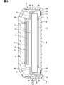
- FIG. 1 is an external perspective view showing an overall image of a vehicle display device. It is sectional drawing which shows the internal structure of the display apparatus for vehicles. It is sectional drawing which expands and shows the internal structure near the upper surface part. It is a figure for demonstrating the collision mode of the head with respect to the display apparatus for vehicles. It is a figure for demonstrating the subject of a comparison structure. It is a figure for demonstrating the effect of embodiment. It is a figure which shows the modification of the shape of an internal frame edge part.
- FIG. 10 is a diagram showing an internal configuration of a vehicle display device of Modification 2; It is a figure which shows an example of the shape of a reinforcement member. It is a figure which shows another example of the shape of a reinforcement member. It is a figure which shows another example of the shape of a reinforcement member.
- FIGS. 1 and 2 are diagrams showing an example of a schematic configuration of a vehicle display device 100 according to the present disclosure.
- the vehicle display device 100 is installed on an instrument panel 200 of the vehicle and is configured as a device that displays various information. More specifically, the vehicular display device 100 is arranged in a region of the upper surface of the instrument panel 200 located in the central portion in the vehicle width direction with the display surface of the display 1 facing the rear of the vehicle.
- the direction in which information is displayed on the vehicle display device 100 is referred to as the viewing side.
- the viewing side corresponds to the front side of the vehicular display device 100.
- the driver's seat is provided on the right side of the vehicle in FIG. 1, the vehicle provided with the vehicle display device 100 may be a vehicle having the driver's seat on the left side.
- the vehicle display device 100 may be used in a fully autonomous vehicle having no driver seat.
- the vehicle display device 100 is preset with the vertical direction and the horizontal direction.
- the vehicle display device 100 is attached so that the vertical direction is substantially parallel to the vertical direction of the vehicle.
- the vehicle display device 100 is attached so that the left-right direction is substantially parallel to the left-right direction of the vehicle (in other words, the vehicle width direction).
- the term “substantially parallel” includes not only the completely parallel state but also the state of being inclined by about 30° from the completely parallel state. That is, the vehicular display device 100 is attached to the instrument panel 200 in such a posture that an occupant seated in the driver's seat can recognize the display screen of the display 1 with respect to the horizontal surface of the vehicle without feeling uncomfortable. Is also good.
- the vehicle horizontal plane refers to a plane perpendicular to the height direction of the vehicle.
- the vehicle display device 100 includes a display surface 110 on which an image is displayed, a device side surface portion 120, and a device back surface portion.
- the rear surface of the device refers to the surface opposite to the display surface 110.
- the device side surface portion 120 corresponds to a surface formed along the viewing direction in the vehicular display device 100.
- the vehicle display device 100 includes a left side surface portion, a right side surface portion, an upper surface portion 120A, and a lower surface portion as the device side surface portion 120 so as to correspond to the vertical and horizontal directions of the vehicle display device 100.
- the vehicle display device 100 is formed in a flat rectangular parallelepiped shape whose thickness direction is a direction perpendicular to the display surface 110.
- the vehicle display device 100 is formed such that the length in the left-right direction is longer than the length in the up-down direction.
- the viewing direction in the vehicular display device 100 can be understood as a direction along the normal line of the display surface 110.
- the lower surface part is provided with a coupling part 130 for fixing the vehicle display device 100 to the instrument panel 200, for example.
- the vehicle display device 100 is fixed to the instrument panel 200 by inserting the coupling portion 130 into an insertion hole (not shown) provided in the instrument panel 200.
- various methods such as screwing can be adopted.
- the coupling unit 130 is an arbitrary element.
- the upper surface portion 120A corresponds to a portion of the surrounding member 5 described below that is located above the display 1.
- a portion of the surrounding member 5 located above the display 1 corresponds to an upper surrounding portion.
- the visible side end of the upper surrounding portion corresponds to the upper visible side end.
- the “viewing side end of the surrounding member 5” below refers to the viewing side end of the portion of the surrounding member 5 located above the display 1 (that is, the upper surface 120A).
- the following description can be applied to a portion other than the upper surface portion 120A.
- the side surface portion of a certain member refers to a surface of the member facing a direction substantially orthogonal to the viewing direction.
- the visual recognition side end of a certain member refers to the frontmost end (that is, the front end) of the member.
- the vehicle display device 100 is realized by combining a display 1, a circuit board 2, an inner case 3, a back case 4, an enclosing member 5, and a cover member 6.
- the configuration in which the rear case 4 and the surrounding member 5 are combined corresponds to a housing for the display 1.
- the inner case 3, the circuit board 2, and the display 1 are arranged in this order on the rear case 4.
- FIG. 3 in order to clearly show the boundaries of the respective members, some of the members that are supposed to be in contact with each other are shown separated from each other.
- the display 1 is a device that is driven based on a control signal from a display controller mounted on the circuit board 2 to display an image.
- the display 1 corresponds to the display unit.
- the display 1 includes a rectangular display surface as an example.
- the display 1 is configured to be capable of full color display.
- various displays such as a liquid crystal display, an organic EL (Electro-Luminescence) display, and a plasma display can be adopted.
- the display 1 is realized by using a liquid crystal panel 11 using a thin film transistor (TFT) and a backlight 12.
- the liquid crystal panel 11 is, for example, an active matrix type liquid crystal panel formed from a plurality of liquid crystal pixels arranged in a two-dimensional direction.
- the backlight 12 is a light source panel that emits light toward the liquid crystal panel 11.
- the backlight 12 is realized by using one or a plurality of LEDs.
- the backlight 12 is arranged on the back side of the liquid crystal panel 11.
- the liquid crystal panel 11 is fixed to the backlight 12 via a light source frame 13 attached to the edge of the backlight 12.
- the light source frame 13 and the liquid crystal panel 11 may be bonded with an elastic adhesive or an elastic double-sided tape.
- the elastic double-sided tape refers to a double-sided tape having elasticity (in other words, cushioning property, stretchability) in which an adhesive is applied to both surfaces such as a nonwoven fabric and sponge.
- the elastic double-sided tape is, for example, a double-sided tape using acrylic foam.
- the light source frame 13 may be formed of a metal material such as aluminum, magnesium, stainless steel, or a steel plate, or may be realized by using a resin material such as polycarbonate (PC: polycarbonate).
- PC polycarbonate
- the backlight 12 is configured by a direct type, but as another aspect, the backlight 12 may be configured by an edge light type.
- the circuit board 2 is a board on which an electric circuit of the vehicle display device 100 is formed.
- the circuit board 2 is formed in a flat plate shape with a synthetic resin such as glass epoxy.
- a display controller, a power supply circuit, etc. are mounted on the circuit board 2.
- the circuit board 2 is arranged on the back side of the display 1 so as to face the display 1.
- the circuit board 2 is fixed to the inner case 3 so as to be sandwiched between the inner case 3 and the display 1 (specifically, the backlight 12 ).
- the circuit board 2 may be arranged on the back side of the inner case 3.
- the circuit board 2 may be arranged between the inner case 3 and the rear case 4.
- the inner case 3 is a member that covers the display 1 and the circuit board 2 from the back side and integrally supports these.
- the inner case 3 is configured to have a light-shielding property by using, for example, a synthetic resin such as polycarbonate.
- the inner case 3 may be formed of a metal material such as aluminum, magnesium, stainless steel, or a steel plate.
- the inner case 3 may be configured by combining a plurality of parts.
- the inner case 3 is formed in the shape of a rectangular plate with a bottom, the edge portion of which is formed to spread outward at another stage. Specifically, the display receiving portion 31 for supporting the display 1 from the back side, the recess 32 formed so as to fall from the display receiving portion 31 to the back side, and the inner frame 33 covering the side surface portion of the display 1. And
- the display receiving portion 31 is configured to be substantially flat so as to come into contact with the edge of the back surface of the display 1.
- the contact here includes not only the actual contact but also the condition that the separation distance is 0.1 mm or less (that is, the condition where the contact is extremely close).
- the display receiving portion 31 is set to have substantially the same size as the back surface portion of the display 1. Specifically, the display receiving portion 31 is formed to be larger than the display 1 by a small amount (for example, about several millimeters) so that the inner frame 33 provided upright on the edge thereof can accommodate the display 1. ..
- the display receiving portion 31 is provided with an opening serving as a visible side end of the concave portion 32 (a convex portion according to another aspect) at a portion separated from the edge portion by a certain distance. That is, the display receiving portion 31 is configured as a rectangular plate-shaped member having an opening.
- the recess 32 has a bottom plate 321 that is formed to have substantially the same size as the opening of the display receiver 31, and a recess wall 322 that connects the edge of the bottom plate 321 and the opening of the display receiver 31.
- the bottom plate portion 321 is formed so as to face the back surface portion of the display 1 at a predetermined interval.
- the recessed wall portion 322 extends from the opening of the display receiving portion 31 toward the back side.
- the circuit board 2 described above is fixed to the bottom plate portion 321. If the bottom plate portion 321 is regarded as the first bottom portion that is the rearmost bottom portion in the inner case 3, the display receiving portion 31 corresponds to the second bottom portion formed outside the first bottom portion and on the viewing side.
- the recessed wall portion 322 corresponds to a configuration that connects the first bottom portion and the second bottom portion.
- the internal frame 33 is configured to extend from the edge of the display receiving portion 31 toward the viewing side.
- the inner frame 33 is formed along the side surface of the display 1.
- the inner frame 33 corresponds to the inner frame portion.
- An end portion of the inner frame 33 on the visible side (hereinafter, the inner frame end portion 331) is separated from the side surface portion of the display 1 by 1.0 mm or more, and an inner side surface of the surrounding member 5 described later (in particular, the bezel back side portion 54). It is configured to be close to.
- Proximity here means a state where the separation is within 2.0 mm, for example.
- the inner frame end 331 corresponds to the visible side end of the inner frame.
- the inner frame 33 has a side surface supporting portion 332 configured to come into contact with a side surface portion of the display 1 and a side surface supporting portion with a distance from the side surface portion of the display 1. And a separating portion 333 that is set to be larger than 332.
- the side surface support portion 332 corresponds to a configuration for protecting the side surface portion of the display 1 and restricting the movement of the display 1 in the left-right and up-down directions.
- the size of the spacing portion 333 is adjusted so that the spacing D1 from the inner peripheral surface of the surrounding member 5 is about 1 mm.
- the inner frame end portion 331 corresponds to the visible side end portion of the separating portion 333.
- the spacing portion 333 including the inner frame end portion 331 plays a role of suppressing the deformation of the surrounding member 5 from the inside. Specifically, the cover receiving portion 52 and the like of the surrounding member 5 are prevented from being deformed downward.
- such a configuration of the internal frame 33 corresponds to a configuration in which the internal frame 33 expands in multiple stages from the back side toward the viewing side.
- the inner case 3 is fixed to the rear case 4 by a snap fit mechanism, for example.
- the method for maintaining the state in which these members are combined (hereinafter referred to as the fixing method) is not limited to this.
- the inner case 3 and the rear case 4 may be joined by screwing or welding.
- the back case 4 is a structure for supporting the inner case 3 from the back side.
- the back case 4 is made of a synthetic resin such as polycarbonate so as to have a light blocking effect.
- the rear case 4 is formed to have a necessary and sufficient size for accommodating the inner case 3.
- the back case 4 is formed in a rectangular dish shape with a bottom. That is, the rear case 4 has a shape in which the edge portion is gradually curved toward the viewing side with respect to the bottom portion.
- a fitting groove for fitting with a fitting claw provided on the back side of the surrounding member 5 is provided on the outer peripheral portion of the back case 4. Illustration of the fitting claws and the fitting grooves is omitted. It suffices that the fitting groove is provided at a position corresponding to the fitting claw, and the number and forming place thereof may be appropriately designed.
- the fitting groove may be formed over the entire circumference. From the viewpoint of improving waterproofness, an O-ring or the like may be arranged at the connecting portion between the back case 4 and the surrounding member 5. That is, various waterproof and dust-proof structures can be applied to the connection portion between the back case 4 and the surrounding member 5.
- the back case 4 and the surrounding member 5 may be fixed by screws, welding, or an elastic adhesive.
- the surrounding member 5 is a cylindrical member that surrounds the inner case 3 including the display 1 from the side to the entire circumference.
- the lateral direction here means a direction orthogonal to the thickness direction of the display 1.
- the visible end and the rear end of the surrounding member 5 are formed as openings.
- the tubular shape here is not limited to a cylindrical shape having a circular/elliptical cross section, and includes a rectangular tubular shape having a rectangular cross section.
- the surrounding member 5 is made of a resin material such as PC resin so as to have a light shielding property.
- the surrounding member 5 integrally includes a peripheral wall portion 51, a cover receiving portion 52, and a bezel portion 53.
- the configurations such as the peripheral wall portion 51, the cover receiving portion 52, and the bezel portion 53 all indicate a part of the surrounding member 5.
- the configuration including the peripheral wall portion 51, the cover receiving portion 52, and the bezel portion 53 is physically (in other words, as a substance) integrally and continuously connected.
- the peripheral wall portion 51 is a portion that surrounds the display 1, the circuit board 2, and the inner case 3 from the outer peripheral side by being fitted to the rear case 4.
- the peripheral wall portion 51 corresponds to the main body portion of the surrounding member 5.
- a fitting claw for engaging with a fitting groove provided in the outer peripheral portion of the back case 4 is provided at the rear end of the peripheral wall portion 51.
- a cover receiving portion 52 is formed at an end portion on the visible side of the peripheral wall portion 51 so as to project radially inward. From another viewpoint, the peripheral wall portion 51 corresponds to a tubular structure extending from the cover receiving portion 52 toward the viewing side.
- the cover receiving portion 52 is configured to support the edge portion of the cover member 6 from the back side.
- the cover receiving portion 52 is continuously provided so as to make a round around the inside of the peripheral wall portion 51.
- the visible portion of the cover receiving portion 52 is flat so as to be parallel to the display surface of the display 1.
- the protrusion amount D2 of the cover receiving portion 52 with respect to the peripheral wall portion 51 is set to, for example, 10 mm.
- the protrusion amount D2 of the cover receiving portion 52 with respect to the peripheral wall portion 51 may be set to another value such as 8 mm or 12 mm.
- the width D3 of the portion of the cover receiving portion 52 on which the cover member 6 is placed (hereinafter, the placement surface 521) is set to 7 mm, for example.
- the width D3 of the mounting surface 521 may be 5 mm or the like.
- a portion of the cover receiving portion 52 located on the back side of the mounting surface 521 is formed in a curved shape having a predetermined radius of curvature so as to be continuously connected to the inner side surface of the peripheral wall portion 51. That is, the cover receiving portion 52 projects inward from the inner surface portion of the peripheral wall portion 51 in a semi-arched shape.
- the radius of curvature is, for example, 5 mm, 10 mm, 20 mm, or the like, and the bezel portion 53 is displaced downward (in other words, the direction in which the cover member 6 is present) by the impact from the diagonally upper side on the viewing side that acts on the bezel portion 53. It should have been done.
- the boundary portion between the peripheral wall portion 51 and the cover receiving portion 52 corresponds to the portion located on the back side of the bezel portion 53. Therefore, this portion is referred to as the bezel back side portion 54.
- the back side portion 54 of the bezel corresponds to the back side portion of the cover receiving portion 52.
- the cover receiving portion 52 extends inward from the inner surface portion of the peripheral wall portion 51 in a semi-arched shape, but is not limited to this.
- the cover receiving portion 52 may be formed so as to stand up from the inner surface portion of the peripheral wall portion 51 toward the inside.
- the bezel portion 53 is a portion of the enclosing member 5 that is located on the visible side of the cover receiving portion 52.
- the bezel portion 53 is erected on the edge portion of the cover receiving portion 52 so as to surround the edge portion (in other words, the edge portion) of the cover member 6.
- the bezel portion 53 is erected substantially perpendicular to the mounting surface 521 so as not to cover the visible side surface of the cover member 6. That is, the surrounding member 5 is configured so as not to cover the visible side surface of the cover member 6.
- the thickness D4 of the bezel portion 53 is set to 2.5 mm, for example.
- the outer edge of the bezel portion 53 is chamfered. For example, the width of the bezel portion 53 is gradually reduced from the innermost portion toward the tip portion.
- the thickness D4 of the bezel portion 53 corresponds to the width of the surrounding member 5 that is visible around the cover member 6. Further, the thickness D4 of the bezel portion 53 corresponds to the vertical width of the upper visual recognition side end portion.
- the thickness D4 of the bezel portion 53 may be set to 10 mm or less. Further, the thickness D4 of the bezel portion 53 is preferably set to 5.0 mm or less at the most from the viewpoint of designability. The thickness D4 of the bezel portion 53 is more preferably set to 3.0 mm or less from the viewpoint of designability.
- the height (the length in the viewing direction) D5 of the bezel portion 53 with respect to the mounting surface 521 has a likelihood of 0.5 mm added to the value obtained by adding the thickness D6 of the cover member 6 and the thickness D7 of the elastic adhesive member 7. Is set to the given value.
- the height D5 of the bezel portion 53 with respect to the mounting surface 521 is set to 2.4 mm. That is, the tip portion of the bezel portion 53 is configured so as to project by 0.5 mm from the visible side surface of the cover member 6. Since the amount D8 of protrusion of the bezel portion 53 with respect to the cover member 6 is extremely small, the bezel portion 53 does not function as a dial plate (in other words, a hood).
- the bezel portion 53 may be configured such that the protrusion amount D8 of the bezel portion 53 with respect to the cover member 6 is 0.1 mm or more and 2.0 mm or less. It suffices that the bezel portion 53 is configured to project beyond the surface of the cover member 6 on the viewing side, and the projection amount D8 is more preferably 0.3 mm or more. Further, from the viewpoint of design, it is preferable that the bezel portion 53 is configured such that the protrusion amount D8 of the bezel portion 53 with respect to the cover member 6 is 1.0 mm or less.
- the cover member 6 is configured to protect the display surface of the display 1.
- the cover member 6 is a transparent plate member.
- the cover member 6 is made of glass.
- the glass here includes tempered glass.
- the cover member 6 is preferably made of glass from the viewpoint of translucency, but as another aspect, the cover member 6 may be made of resin such as acrylic or polycarbonate.
- the thickness D6 of the cover member 6 is set to about 1.5 mm.
- the thickness D6 of the cover member 6 can be changed as appropriate.
- the cover member 6 may have a thickness D6 of 0.25 mm, 0.5 mm, 1.0 mm, 2.0 mm, or the like.
- the cover member 6 is formed to have substantially the same inner dimension as the bezel portion 53 of the surrounding member 5. Specifically, the cover member 6 is formed in such a size that a gap of about 0.5 mm is formed between the cover member 6 and the bezel portion 53 (that is, a small amount is small) in a state of being attached to the surrounding member 5. According to the configuration in which the distance D9 between the bezel portion 53 and the cover member 6 is set to about 0.5 mm, the bezel portion 53 and the cover member 6 come into contact with each other due to the difference in linear expansion coefficient between the two. It is possible to reduce the risk that stress is applied to the cover member 6.
- the distance D9 between the bezel portion 53 and the cover member 6 may be set to 0.1 mm or more and 2.0 mm or less.
- the manufacturing target value (design value) of the separation D9 between the bezel portion 53 and the cover member 6 may be 0.2 mm, 0.8 mm, 1.0 mm, 1.5 mm, or the like.
- the cover member 6 is bonded to the mounting surface 521 of the surrounding member 5 by using a predetermined elastic bonding member 7 so as to close the opening of the surrounding member 5 on the visible side.
- the elastic adhesive member 7 is realized by using an elastic adhesive or an elastic double-sided tape.
- the thickness D7 of the elastic adhesive member 7 is set to 0.4 mm. Since the cover member 6 is fixed to the surrounding member 5 by the elastic adhesive member 7, the displacement of the mounting surface 521 due to the impact on the upper end portion of the vehicle display device 100 acts on the cover member 6 as bending stress. Can ease things. Further, the elastic adhesive member 7 can absorb the stress (so-called thermal stress) generated due to the difference in linear expansion coefficient between the cover member 6 and the surrounding member 5. Therefore, it is possible to prevent the cover member 6 from cracking due to thermal deformation of the surrounding member 5.
- the linear expansion coefficient here means the rate at which the length of an object changes in response to an increase in temperature.
- the cover member 6 is bonded to the display surface of the display 1 by using a predetermined translucent resin material (hereinafter, optical bonding material). That is, the cover member 6 is optically bonded to the display 1.
- the cover member 6 will be referred to as an optical adhesive layer 8 that is a resin layer that fills a gap with the display 1.
- the optical binding material a resin that is colorless and transparent and has elasticity may be used, and various resin materials can be adopted. Acrylic, silicone, and urethane resins (so-called OCR: Optical Clear Resin) are suitable as the optical bonding material.
- the optical adhesive layer 8 may be realized by using a sheet-shaped OCA (Optical Clear Adhesive).
- the optical adhesive layer 8 is provided between the display 1 and the cover member 6, it is possible to suppress light reflection and improve visibility. Due to the translucency, the cover member 6 and the optical adhesive layer 8 allow the occupant to visually see the display of the display 1.
- the optical adhesive layer 8 is an optional element and can be omitted.
- the vehicle display device 100 is disposed below the occupant's head, and is arranged in a range in which the occupant's head can collide due to the impact of a front end collision of the vehicle (hereinafter, head impact range). sell.
- head impact range a range in which the occupant's head can collide due to the impact of a front end collision of the vehicle
- FIG. 5 is a configuration for testing a position where a spherical head model Md having a diameter of 165 mm, which imitates the head of an occupant, collides with the vehicle display device 100 placed on the instrument panel 200, and , The collision position is shown.
- the head collision range here is, for example, a range in which the spherical head model Md statically contacts when the spherical head model Md is rotated from a predetermined rotation center C at a predetermined rotation radius R.
- the radius of gyration R may be set to a value corresponding to the distance from the hip joint point of the human body to the center of the head, such as 705 mm.
- the radius of gyration R may be adjusted within the range of 654.5 mm to 755.5 mm.
- the center of rotation C can be a seating reference point, for example.
- the seating reference point refers to a position of a hip joint point when a human body model is seated on a seat such as a driver's seat by a seating method defined in ISO6549-1980, or a design standard position set on a seat corresponding to this.
- the center of rotation C has moved a predetermined amount (eg, 127 mm) forward of the seating reference point and a predetermined amount (eg, 19 mm) vertically upward. Points can be adopted.
- the direction in which the impact from the head acts on the collision position is the direction perpendicular to the tangent line at the collision position (that is, the normal direction at the collision position).
- the head model collision test may be carried out on the assumption that a vehicle traveling at a speed of 20 km/h collides with the front end.
- the collision speed of the head model may be set to 20 ⁇ 1 km/h.
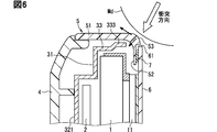
- the bezel portion 53 is impacted by a head collision.
- the head portion can directly collide with the edge portion 61 of the cover member 6 by being displaced upward/backward. Therefore, the cover member 6 is relatively easily cracked.
- the edge portion 61 is also referred to as a terminal portion.
- the edge portion 61 also includes a corner portion.
- the solid arrow in FIG. 6 indicates the action direction of the impact (that is, the collision direction), and the broken arrow indicates the displacement direction of the bezel portion 53.
- the front end portion of the surrounding member 5 (that is, the bezel portion 53) is configured to project from the surface of the cover member 6 by a small amount toward the visible side. Therefore, the primary collision position with the head of the occupant is the bezel portion 53 of the upper surface portion 120A. In other words, it is possible to prevent the impact due to the collision between the vehicle display device 100 and the head from being directly applied to the edge portion of the cover member 6. Further, since the bezel portion 53 projects toward the viewing side with respect to the surface of the cover member 6, the bezel portion 53 does not displace upward/backward due to an impact, but displaces downward as shown in FIG. try to.
- the bezel portion 53 continues to be interposed between the head portion and the edge portion 61 of the cover member 6, and it is possible to reduce the risk that a collision impact acts on the edge portion 61 of the cover member 6.
- the broken line arrow in FIG. 7 indicates the displacement direction of the bezel portion 53.
- the downward displacement of the bezel portion 53 is restricted by the inner frame end portion 331.
- the inner side surface of the peripheral wall portion 51 and the inner frame end portion 331 come into contact with each other, so that the bezel portion 53 is prevented from being displaced significantly downward. it can.
- the thickness D4 of the bezel portion 53 is set to 2.5 mm, and the outer edge portion of the bezel portion 53 is chamfered. With such a configuration, it is possible to achieve both design and panel rigidity.
- the cover member 6 cracks according to the configuration in which the thickness D4 of the bezel portion 53 is set to 2.0 mm and the protrusion amount D8 is set to 0.5 mm. It has been confirmed that the probability can be suppressed within a predetermined allowable range. That is, according to the configuration of the present embodiment, the cover member 6 can be made difficult to break.
- the thickness of the elastic adhesive member 7 is set to 0.4 mm.
- the elastic adhesive member 7 absorbs the thermal stress resulting from the difference in the coefficient of thermal expansion (for example, the coefficient of linear expansion) between the cover member 6 and the surrounding member 5. Therefore, the risk that the cover member 6 and the surrounding member 5 are cracked by thermal stress can be reduced.
- the configuration that is, the housing
- the configuration that is, the housing
- the configuration that provides the appearance of the vehicular display device 100, such as the surrounding member 5 and the rear case 4
- Such a structure has an advantage that a complicated design can be easily realized, as compared with a structure in which the housing is realized by using a metal material.
- thermoplastic resin such as polybutylene terephthalate (PBT) or polyphenylene sulfide (PPS) can be used in addition to the PC resin.
- a synthetic resin obtained by mixing PC resin with acrylonitrile butadiene styrene copolymer (ABS) resin may be used.
- various resins such as polypropylene (PP) can be used.
- PC resin or a synthetic resin in which ABS resin is mixed with PC resin from the viewpoint of impact resistance, heat resistance, and workability.
- the elastic adhesive described above one having a predetermined elasticity in a cured state is preferable.
- elastic adhesives such as those containing silicone rubber as the main component (so-called silicone adhesives), those containing polyurethane as the main component, those containing rubber as the main component, and those containing acrylic monomer as the main component. It is possible to use various materials. It is preferable that the elastic adhesive is mainly composed of a highly viscous elastomer.
- the silicone-based pressure-sensitive adhesive also includes one having a modified silicone resin as a main component.
- the elastic adhesive is a pressure-sensitive adhesive that maintains stickiness and elasticity without solidifying in a temperature range that can be taken by the vehicle instrument panel surface (for example, -40°C to 110°C) (in other words, It is preferably an adhesive).
- the elastic adhesive various elastic adhesives such as moisture-curing type and ultraviolet-curing type can be used.
- the elastic adhesive used in the vehicle display device 100 is preferably a hot-melt type adhesive.
- the hot-melt type elastic adhesive is suitable from the viewpoint of manufacturability (workability), since the coating amount (height, width) can be controlled by using a liquid quantitative discharge device (so-called dispenser).
- the vehicular display device 100 is configured by using a pressure sensitive adhesive containing a one-liquid type modified silicone resin as a main component as the elastic adhesive.
- the hot-melt type elastic adhesive is an adhesive that melts at a predetermined temperature (for example, 110° C.) or higher and cures at the temperature or lower, and corresponds to an elastic adhesive having thermoplasticity.
- a predetermined temperature for example, 110° C.
- a two-liquid mixed type adhesive can also be adopted.
- the inner frame end portion 331 may be configured to have a circular cross-sectional shape, as shown in FIG. According to this structure, the rigidity of the surrounding member 5 against a head collision can be further improved. Note that the inner frame end portion 331 may be configured to contact the back side portion 54 of the bezel. Further, as shown in FIG. 9, the inner frame 33 may be formed such that its end portion is along the back side portion 54 of the bezel. With the above configuration, the inner frame 33 acts to increase the rigidity of the surrounding member 5.
- the inner frame end portion 331 is preferably configured to function as a reinforcing portion that enhances the rigidity of the surrounding member 5.
- a reinforcing member 9 may be disposed near the back side portion 54 of the bezel for improving the rigidity against a head collision with the upper end of the surrounding member 5.
- the reinforcing member 9 is, for example, a cylindrical/cylindrical member, and is arranged in parallel to the left and right below the back side portion 54 of the bezel located above the display 1.
- the reinforcing member 9 may be fixed to, for example, the inner surface of the surrounding member 5 corresponding to the left side surface portion or the right side surface portion.
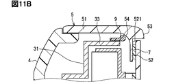
- the reinforcing member 9 may be attached to the inner frame end portion 331 as shown in FIGS. 11A to 11C.
- the reinforcing member 9 may be configured so as to enhance the rigidity of the surrounding member 5, and its cross-sectional shape may be an L-shape as shown in FIG. 11A, or a circular end as shown in FIG. 11B. It may be formed to have a portion.
- the reinforcing member 9 may be formed along the back side portion 54 of the bezel.
- the reinforcing member 9 may be made of resin, or may be realized by using stainless steel or copper material.
- the shape of the reinforcing member 9 is not limited to the columnar shape or the cylindrical shape.
- the reinforcing member 9 may be configured as a leaf spring so as to easily follow the curved surface shape.
- the reinforcing member 9 may be introduced into the configuration disclosed as the above-described embodiment or modification 1.
- the vehicle display device 100 may include a touch panel.
- a touch panel may be arranged between the cover member 6 and the optical adhesive layer 8.
- the surface of the cover member 6 may be subjected to AR (Anti-Reflection) processing, or an antireflection film may be attached.
- AR processing the cover member 6 may be subjected to AG (anti-glare) processing.
- the cover member 6 may be provided with a viewing angle control film for controlling the light output direction of the image light.
- the viewing angle control film is also called a louver film (LAF: Louver Array Film). According to the configuration in which the viewing angle control film is provided on the cover member 6, it is possible to prevent the display screen of the display 1 from being reflected on the windshield.
- LAF Louver Array Film
- the vehicle display device 100 may be configured as a device having a curved display surface (so-called curved display), as shown in FIGS. 12A and 12B.
- the curved direction of the display surface is not limited to the direction illustrated in FIGS. 12A and 12B, and can be changed as appropriate.
- the display surface of the vehicular display device 100 is not limited to the rectangular shape, and may be an elliptical shape or the like.
- the vehicle display device 100 may be used by being attached to a part other than the instrument panel 200. Further, it may be mounted and used at a position where a passenger in the back seat can be visually recognized.
- the vehicle display device 100 may be used by being attached to the back portion of the backrest portion of the front seat so that the occupant in the rear seat can visually recognize it.
- the vehicle display device 100 may be attached and used within a certain distance from the seat.
- the vehicle display device 100 may be used by being attached to a position separated from the seat by a certain distance or more (for example, outside the head collision range).
Landscapes
- Engineering & Computer Science (AREA)
- Computer Hardware Design (AREA)
- Theoretical Computer Science (AREA)
- General Engineering & Computer Science (AREA)
- Mechanical Engineering (AREA)
- Transportation (AREA)
- Chemical & Material Sciences (AREA)
- Combustion & Propulsion (AREA)
- General Physics & Mathematics (AREA)
- Physics & Mathematics (AREA)
- Human Computer Interaction (AREA)
- Instrument Panels (AREA)
- Devices For Indicating Variable Information By Combining Individual Elements (AREA)
- Fittings On The Vehicle Exterior For Carrying Loads, And Devices For Holding Or Mounting Articles (AREA)
Priority Applications (1)
| Application Number | Priority Date | Filing Date | Title |
|---|---|---|---|
| US17/391,628 US11904689B2 (en) | 2019-02-05 | 2021-08-02 | Display device for vehicle |
Applications Claiming Priority (2)
| Application Number | Priority Date | Filing Date | Title |
|---|---|---|---|
| JP2019018886A JP6950715B2 (ja) | 2019-02-05 | 2019-02-05 | 車両用表示装置 |
| JP2019-018886 | 2019-02-05 |
Related Child Applications (1)
| Application Number | Title | Priority Date | Filing Date |
|---|---|---|---|
| US17/391,628 Continuation US11904689B2 (en) | 2019-02-05 | 2021-08-02 | Display device for vehicle |
Publications (1)
| Publication Number | Publication Date |
|---|---|
| WO2020162108A1 true WO2020162108A1 (ja) | 2020-08-13 |
Family
ID=71947091
Family Applications (1)
| Application Number | Title | Priority Date | Filing Date |
|---|---|---|---|
| PCT/JP2020/000811 Ceased WO2020162108A1 (ja) | 2019-02-05 | 2020-01-14 | 車両用表示装置 |
Country Status (3)
| Country | Link |
|---|---|
| US (1) | US11904689B2 (https=) |
| JP (1) | JP6950715B2 (https=) |
| WO (1) | WO2020162108A1 (https=) |
Cited By (1)
| Publication number | Priority date | Publication date | Assignee | Title |
|---|---|---|---|---|
| US20240276655A1 (en) * | 2023-02-13 | 2024-08-15 | Charles Jarod Gharamti | Novel touch screen assembly using improved bonding method |
Families Citing this family (7)
| Publication number | Priority date | Publication date | Assignee | Title |
|---|---|---|---|---|
| KR102797828B1 (ko) * | 2019-04-12 | 2025-04-22 | 현대자동차주식회사 | 사이드링크 통신을 수행하는 방법 및 그 장치 |
| WO2020239851A1 (de) * | 2019-05-28 | 2020-12-03 | Behr-Hella Thermocontrol Gmbh | Anzeigevorrichtung für ein fahrzeug |
| JP7559624B2 (ja) * | 2021-03-05 | 2024-10-02 | 株式会社デンソー | 表示装置 |
| JP7436414B2 (ja) * | 2021-03-26 | 2024-02-21 | トヨタ自動車株式会社 | 車両構造 |
| DE102021131779A1 (de) * | 2021-12-02 | 2023-06-07 | Marelli Stuttgart (Germany) GmbH | Verfahren zum Zusammenbau einer Anzeigeeinheit eines Kraftfahrzeugs und nach dem Verfahren zusammengebaute Anzeigeeinheit |
| EP4227138B1 (en) * | 2022-02-15 | 2024-10-16 | Marelli Europe S.p.A. | Display assembly, in particular for a motor vehicle dashboard, and assembling method for assembling such an assembly |
| US20250093693A1 (en) * | 2023-09-19 | 2025-03-20 | Shanghai Tianma Micro-electronics Co., Ltd. | Display device and manufacturing method for display device |
Citations (4)
| Publication number | Priority date | Publication date | Assignee | Title |
|---|---|---|---|---|
| US20130169125A1 (en) * | 2011-12-30 | 2013-07-04 | Sony Ericsson Mobile Communications Ab | Corner improvement in window carrier for crack window |
| JP2015184397A (ja) * | 2014-03-24 | 2015-10-22 | 京セラディスプレイ株式会社 | 表示装置 |
| JP2016122151A (ja) * | 2014-12-25 | 2016-07-07 | アルパイン株式会社 | 表示装置 |
| JP2018045053A (ja) * | 2016-09-13 | 2018-03-22 | パナソニックIpマネジメント株式会社 | 携帯型情報端末及びその製造方法 |
Family Cites Families (4)
| Publication number | Priority date | Publication date | Assignee | Title |
|---|---|---|---|---|
| JP6702067B2 (ja) | 2016-08-03 | 2020-05-27 | Agc株式会社 | カバー部材および表示装置 |
| JP7036058B2 (ja) * | 2019-02-20 | 2022-03-15 | 株式会社デンソー | 表示装置、および、表示装置の製造方法 |
| US10914973B2 (en) * | 2019-06-19 | 2021-02-09 | Wuhan China Star Optoelectronics Technology Co., Ltd. | Liquid crystal display device |
| CN116819839A (zh) * | 2019-09-29 | 2023-09-29 | 群创光电股份有限公司 | 电子装置 |
-
2019
- 2019-02-05 JP JP2019018886A patent/JP6950715B2/ja active Active
-
2020
- 2020-01-14 WO PCT/JP2020/000811 patent/WO2020162108A1/ja not_active Ceased
-
2021
- 2021-08-02 US US17/391,628 patent/US11904689B2/en active Active
Patent Citations (4)
| Publication number | Priority date | Publication date | Assignee | Title |
|---|---|---|---|---|
| US20130169125A1 (en) * | 2011-12-30 | 2013-07-04 | Sony Ericsson Mobile Communications Ab | Corner improvement in window carrier for crack window |
| JP2015184397A (ja) * | 2014-03-24 | 2015-10-22 | 京セラディスプレイ株式会社 | 表示装置 |
| JP2016122151A (ja) * | 2014-12-25 | 2016-07-07 | アルパイン株式会社 | 表示装置 |
| JP2018045053A (ja) * | 2016-09-13 | 2018-03-22 | パナソニックIpマネジメント株式会社 | 携帯型情報端末及びその製造方法 |
Cited By (1)
| Publication number | Priority date | Publication date | Assignee | Title |
|---|---|---|---|---|
| US20240276655A1 (en) * | 2023-02-13 | 2024-08-15 | Charles Jarod Gharamti | Novel touch screen assembly using improved bonding method |
Also Published As
| Publication number | Publication date |
|---|---|
| JP6950715B2 (ja) | 2021-10-13 |
| US11904689B2 (en) | 2024-02-20 |
| JP2020126155A (ja) | 2020-08-20 |
| US20210354560A1 (en) | 2021-11-18 |
Similar Documents
| Publication | Publication Date | Title |
|---|---|---|
| JP6950715B2 (ja) | 車両用表示装置 | |
| EP3037871B1 (en) | Display device | |
| US20150138484A1 (en) | Display device | |
| CN103163647B (zh) | 平视显示装置 | |
| JP2020129068A (ja) | 車両用表示装置 | |
| US11932107B2 (en) | Display apparatus comprising a self-illuminated screen element, motor vehicle comprising a display apparatus, and associated operating method | |
| KR20190037340A (ko) | 표시 장치 | |
| US11299096B2 (en) | Rear-view mirror device mounted in a vehicle, vehicle-mounted display device, vehicle-mounted display system | |
| JP6988857B2 (ja) | 車両用表示装置 | |
| US10036908B2 (en) | Medical monitor, electronic apparatus, and video display unit | |
| WO2016046972A1 (ja) | 表示装置及び表示装置の製造方法 | |
| JP7106223B2 (ja) | 表示装置 | |
| JP2009151025A (ja) | 電子機器および画像表示装置 | |
| US20240164038A1 (en) | Vehicle display device with protective film to contain glass fragments | |
| US20250093693A1 (en) | Display device and manufacturing method for display device | |
| US9891660B2 (en) | Display device | |
| KR20260000406A (ko) | 차량용 디스플레이 장치 | |
| JP2025044120A (ja) | 表示装置及び表示装置の製造方法 | |
| JP2024124177A (ja) | 車両用表示装置 | |
| JP2009109886A (ja) | 表示装置 | |
| US20200309998A1 (en) | Display device with touch screen function | |
| JP2025128941A (ja) | 表示装置 | |
| JP2024147309A (ja) | 車両用表示装置 | |
| WO2019244494A1 (ja) | 車両用表示装置 |
Legal Events
| Date | Code | Title | Description |
|---|---|---|---|
| 121 | Ep: the epo has been informed by wipo that ep was designated in this application |
Ref document number: 20752145 Country of ref document: EP Kind code of ref document: A1 |
|
| NENP | Non-entry into the national phase |
Ref country code: DE |
|
| 122 | Ep: pct application non-entry in european phase |
Ref document number: 20752145 Country of ref document: EP Kind code of ref document: A1 |