WO2020162089A1 - 回転電機の固定子及び絶縁部材 - Google Patents
回転電機の固定子及び絶縁部材 Download PDFInfo
- Publication number
- WO2020162089A1 WO2020162089A1 PCT/JP2020/000232 JP2020000232W WO2020162089A1 WO 2020162089 A1 WO2020162089 A1 WO 2020162089A1 JP 2020000232 W JP2020000232 W JP 2020000232W WO 2020162089 A1 WO2020162089 A1 WO 2020162089A1
- Authority
- WO
- WIPO (PCT)
- Prior art keywords
- insulating member
- protrusion
- stator
- coil
- long
- Prior art date
- Legal status (The legal status is an assumption and is not a legal conclusion. Google has not performed a legal analysis and makes no representation as to the accuracy of the status listed.)
- Ceased
Links
Images











Classifications
-
- H—ELECTRICITY
- H02—GENERATION; CONVERSION OR DISTRIBUTION OF ELECTRIC POWER
- H02K—DYNAMO-ELECTRIC MACHINES
- H02K3/00—Details of windings
- H02K3/32—Windings characterised by the shape, form or construction of the insulation
- H02K3/34—Windings characterised by the shape, form or construction of the insulation between conductors or between conductor and core, e.g. slot insulation
-
- Y—GENERAL TAGGING OF NEW TECHNOLOGICAL DEVELOPMENTS; GENERAL TAGGING OF CROSS-SECTIONAL TECHNOLOGIES SPANNING OVER SEVERAL SECTIONS OF THE IPC; TECHNICAL SUBJECTS COVERED BY FORMER USPC CROSS-REFERENCE ART COLLECTIONS [XRACs] AND DIGESTS
- Y02—TECHNOLOGIES OR APPLICATIONS FOR MITIGATION OR ADAPTATION AGAINST CLIMATE CHANGE
- Y02T—CLIMATE CHANGE MITIGATION TECHNOLOGIES RELATED TO TRANSPORTATION
- Y02T10/00—Road transport of goods or passengers
- Y02T10/60—Other road transportation technologies with climate change mitigation effect
- Y02T10/64—Electric machine technologies in electromobility
Definitions
- the present invention relates to a stator of a rotating electric machine.
- High output is required for rotating electrical machines, and it is desired to increase the lamination pressure of the electromagnetic steel plates that make up the stator and to make the coil turn more. Further, the conductor wire of the coil arranged in the stator core is covered with a slot liner made of paper for its fixing and insulation.
- Patent Document 1 Japanese Patent Laid-Open No. 2013-208033 discloses an armature core provided with a plurality of slots in the circumferential direction, an armature winding inserted into the slot and wound around the armature core, and an armature core.
- each slit has a width corresponding to the depth of the slot, and these insulators cooperate with each other in the slot.
- the electric wire individual accommodating space to be inserted while being insulated from each other and adjacent to each other is formed in accordance with the number of electric wires to be inserted into the slot.
- the slots provided in the stator core become longer and the coil conductor wire becomes longer.
- the coil conductor wire may be deformed, and the performance of the rotary electric machine may be deteriorated.
- the slot liner may be deformed and the insulation performance between the coil conductors may be deteriorated.
- Patent Document 1 Although the insulator described in Patent Document 1 is configured by assembling two insulators, it does not solve the above-mentioned problems.
- stator core that prevents deformation of coil conductors and slot liners within slots, has high insulation performance between coils, and is easy to manufacture.
- a stator of a rotating electric machine comprising a coil, an insulating member that is in contact with the coil, and a core portion that forms a housing space for the coil and the insulating member, and the insulating members are combined with each other. It is composed of a first insulating member and a second insulating member forming a rectangle for inserting a coil, and the first insulating member is a plate-shaped first base portion arranged along an inner wall of the accommodation space, and a radial direction.
- a plurality of first protrusions that are arranged side by side and that protrude from the first base toward the second insulating member, wherein the second insulating member is arranged along an inner wall of the accommodation space. And a plurality of second projecting parts that are arranged side by side along the radial direction and project from the second base part toward the first insulating member. And the second protrusion are in contact with each other on a surface extending in the circumferential direction.
- FIG. 3 is a perspective view of the slot liner according to the first embodiment in which a stator coil is mounted.
- FIG. 3 is a view of a stator core on which the slot liner of the first embodiment is mounted, viewed from the axial direction. It is a figure which shows the slot liner of Example 1 mounted in the slot. It is a one part enlarged view of FIG.
- FIG. 9 is a perspective view of a slot liner of Example 2.
- FIG. It is a perspective view of the slot liner of Example 2 in which the stator coil was mounted. It is a figure which shows the slot liner of Example 2M mounted in the slot. It is the figure which expanded a part of FIG. It is the figure which looked at the slot liner of the modification of Example 2 mounted in the slot from the axial direction. It is a one part enlarged view of FIG. 11 is a perspective view of a slot liner of Example 3.
- FIG. It is a perspective view of the slot liner of Example 3 with which the stator coil was mounted. It is the figure which looked at the slot liner of the modification of Example 3 mounted in the slot from the axial direction. It is a partially expanded view of FIG.
- FIG. 20 is an enlarged view of a part of FIG. 19. It is the figure which looked at the slot liner of Example 5 mounted in the slot from the axial direction.
- FIG. 22 is an enlarged view of a part of FIG. 21.
- 16 is a perspective view of a slot liner of Example 6.
- FIG. It is a perspective view of the slot liner of Example 6 with which the stator coil was mounted.
- FIG. 26 is a partially enlarged view of FIG. 25.
- 16 is a cross-sectional view of the slot liner of Example 7.
- FIG. It is a figure which shows the slot liner of Example 7 at the time of inserting a stator coil. It is a figure which shows the slot liner of Example 7 after inserting a stator coil.
- the rotary electric machine according to the present embodiment is a rotary electric machine that is suitable for use in traveling of an automobile.
- a so-called electric vehicle using a rotating electric machine includes a hybrid type electric vehicle (HEV) including both an engine and a rotating electric machine, and a pure electric vehicle (EV) traveling only by the rotating electric machine without using an engine.
- HEV hybrid type electric vehicle
- EV pure electric vehicle
- the rotating electric machine described below can be used for both types.
- FIG. 1 is a schematic diagram showing an overall configuration of a rotary electric machine 100 according to an embodiment of the present invention.
- a part of the rotary electric machine 100 is shown as a cross section to show the inside of the rotary electric machine 100.
- the rotating electrical machine 100 is disposed inside the case 10, and includes a housing 112, a stator 130 having a stator core 132 fixed to the housing 112, and a rotor 150 rotatably disposed in the stator 130.
- the case 10 may be configured by an engine case or a transmission case.
- This rotary electric machine 100 is a three-phase synchronous motor with a built-in permanent magnet.
- a three-phase synchronous motor will be described as an example of the rotary electric machine 100, but the present invention can also be applied to an induction motor.
- the rotary electric machine 100 of the present embodiment operates as an electric motor that rotates the rotor 150 by supplying a three-phase alternating current to the stator coil 138 wound around the stator core 132.
- the rotating electric machine 100 When the rotating electric machine 100 is driven by the engine, the rotating electric machine 100 operates as a generator and outputs three-phase AC generated power. That is, the rotary electric machine 100 has both a function as an electric motor that generates a rotation torque based on electric energy and a function as a generator that generates electric power based on mechanical energy. Functions can be selectively used.
- the stator 130 is fixed to the housing 112.
- the stator 130 is fixed and held in the case 10 by fastening the flange 115 provided on the housing 112 to the case 10 with the bolt 12.
- the rotor 150 fixed to the rotary shaft 118 is supported by the bearings 14A and 14B of the case 10, and is rotatably held inside the stator core 132.
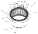
- FIG. 2 is a perspective view showing the stator 130 attached to the housing 112
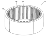
- FIG. 3 is a perspective view of the stator core 132.
- the housing 112 is formed into a cylindrical shape by drawing a steel plate (such as a high-tensile steel plate) having a thickness of about 2 to 5 mm.
- a flange 115 is provided on one end of the housing 112 in the axial direction, and is fixed to the case 10 with a bolt as described above (see FIG. 1 ).
- the flange 115 is formed integrally with the housing 112 by drawing.
- the stator 130 may be directly fixed to the case 10 without providing the housing 112.
- the stator 130 is fixed to the inner peripheral side of the housing 112, and has a cylindrical stator core 132 and a stator coil 138 mounted on the stator core 132.
- the stator core 132 is formed by laminating a plurality of electromagnetic steel plates 133 formed by punching or etching with a thickness of about 0.05 to 1.0 mm, for example.
- the laminated electromagnetic steel plates 133 are connected and fixed by welding, and deformation of the electromagnetic steel plates 133 due to the tightening force when press-fitted into the housing 112 is suppressed.
- a plurality of slots 420 extending in the axial direction are formed in the stator core 132 at equal intervals in the circumferential direction.
- the number of slots 420 is, for example, 72 in this embodiment.
- the stator coil 138 is housed in the slot 420.
- the slot 420 is an open slot, and an opening is formed on the inner peripheral side of the stator core 132.
- the width of the opening in the circumferential direction may be substantially equal to or slightly smaller than the coil mounting portion of each slot 420 in which the stator coil 138 is mounted.
- the slot liner 300 is arranged in each slot 420.
- the slot liner 300 is formed of a resin having heat resistance into a predetermined shape, and has a thickness of about 0.1 to 0.5 mm.
- the slot liner 300 is arranged in the slot 420 and the coil ends 140a and 140b.
- the slot liner 300 is disposed between the coils inserted into the slots 420 and between the coils and the inner surface of the slot 420, and functions as an insulating member to provide a space between the coils and between the coil and the inner surface of the slot 420.
- the dielectric strength is improved.
- the stator coil 138 is formed by connecting a plurality of U-shaped segment coils 28 to each other.
- the segment coil 28 is arranged such that one end thereof is adjacent to the other segment coil 28 so that the end thereof is exposed from the slot 420 (that is, the stator 130), and the other end thereof is further segmented. It is arranged adjacent to the coil 28.
- the segment coils 28 whose ends are adjacent to each other are connected to each other at their adjacent ends to form a stator coil 138 wound around the stator core 132.
- the segment coil 28 may be of a type in which the end exposed from the slot 420 is connected by welding, or may be of a type in which segment coils inserted from both sides of the stator core 132 are connected inside the slot 420. (See FIGS. 28 and 29).
- the slot liner 300 disposed on the coil ends 140a and 140b is annularly disposed between the coils for interphase insulation and interconductor insulation at the coil ends 140a and 140b.
- the slot liner 300 is provided inside the slot 420 and on the coil ends 140a and 140b, it is necessary even if the insulating coating of the coil is damaged or deteriorated. Can maintain high dielectric strength.
- Teeth 430 are formed between slots 420, and each tooth 430 is formed integrally with an annular core back 440.
- the stator core 132 is an integral core in which the teeth 430 and the core back 440 are integrally molded.
- the teeth 430 guide the rotating magnetic field generated by the stator coil 138 to the rotor 150 and cause the rotor 150 to generate a rotating torque.
- the rotor 150 has a rotor core 152 and a permanent magnet 154 held in a magnet insertion hole formed in the rotor core 152.
- the rotor core 152 has rectangular parallelepiped magnet insertion holes formed at equal intervals in the circumferential direction in the vicinity of the outer peripheral portion.
- a permanent magnet 154 is embedded in each magnet insertion hole and is fixed with an adhesive or the like.
- the width of the magnet insertion hole in the circumferential direction is larger than the width of the permanent magnet 154 in the circumferential direction, and magnetic gaps 156 are formed on both sides of the permanent magnet 154.
- An adhesive may be embedded in the magnetic gap 156, or the magnetic gap 156 may be integrally fixed to the permanent magnet 154 with resin.
- the permanent magnet 154 forms the field pole of the rotor 150.
- one permanent magnet 154 forms one magnetic pole, but one magnetic pole may be formed by a plurality of permanent magnets.
- the magnetic flux density of each magnetic pole generated by the permanent magnet is increased, and the magnet torque can be increased.
- a neodymium-based or samarium-based sintered magnet, a ferrite magnet, a neodymium-based bonded magnet, or the like can be used, but the residual magnetic flux density of the permanent magnet 154 is about 0.4 to 1.3T.
- a neodymium magnet is more suitable.
- An auxiliary magnetic pole may be formed between each permanent magnet 154.
- the slot liner 300 of the stator 130 of the present invention includes a first insulating member having a plurality of first protrusions and a second insulating member having a plurality of second protrusions, as illustrated in each of the embodiments described below. And are combined to form an insulator having a ladder-shaped cross section when viewed in the axial direction.
- the first projecting portion and the second projecting portion are in contact with each other not on the cross section but on the side surfaces (surfaces extending in the circumferential direction and facing each other in the radial direction) to form a plurality of rectangular coil insertion holes 330. ..
- the slot liner 300 of the stator 130 of the present invention forms a hollow portion (in which the stator coil 138 is inserted into the hollow portion, not the bean jam), like a skin during a snack. It has a monaca structure.
- the shape of the slot liner 300 of each embodiment will be described in detail.
- FIGS. 4, 5, 6, 7, and 8. 4 is a perspective view of the slot liner 300 of the first embodiment
- FIG. 5 is a perspective view of the slot liner 300 having the stator coil 138 mounted thereon
- FIG. 6 is a stator core 132 having the slot liner 300 mounted therein
- FIG. 7 is an axial view of FIG. 7
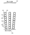
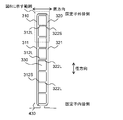
- FIG. 7 is an axial view of the slot liner 300 mounted in the slot 420
- FIG. 8 is an enlarged view of part of FIG. 7.
- the slot liner 300 of the first embodiment forms a plurality of rectangular coil insertion holes 330, and one stator coil 138 is arranged in one coil insertion hole 330.
- the slot liner 300 of the first embodiment includes a first insulating member 310 having a first protruding portion 312 and a second insulating member 320 having a second protruding portion 322, and the first insulating member 310 and the second insulating member. In combination with 320, an even number (eight in the figure) of coil insertion holes 330 is formed.
- one stator coil 138 is arranged in one coil insertion hole 330.
- the first insulating member 310 includes a plate-shaped first base 311 arranged along the inner wall of the slot 420 and a plurality of first bases 311 that vertically project from the first base 311 in the circumferential direction. It is composed of a protruding portion 312.
- the plurality of first protrusions 312 are composed of five first long protrusions 312L and four first short protrusions 312S.
- the first long protrusion 312L has a longer protrusion length from the first base than the first short protrusion 312S.
- the second insulating member 320 includes a plate-shaped second base portion 321 arranged along the inner wall of the slot 420, and a plurality of second protruding portions 322 vertically projecting from the second base portion 321 in the circumferential direction. Composed.
- the plurality of second protrusions 322 include five second long protrusions 322L and four second short protrusions 322S.
- the second long protrusion 322L has a longer protrusion length from the first base than the second short protrusion 322S.
- the first insulating member 310 and the second insulating member 320 have the same shape, and by combining two parts having the same shape as the first insulating member 310 and the second insulating member 320, the slot liner 300 is formed.
- the four first long protrusions 312L and the four second short protrusions 322S from the outer peripheral side are in contact with each other at a side surface (a surface extending in the circumferential direction and facing in the radial direction). Further, the four first short protrusions 312S and the four second long protrusions 322L from the inner peripheral side are in contact with each other at their side surfaces (surfaces extending in the circumferential direction and facing in the radial direction). Further, the middle (fifth in the radial direction) first protruding portion 312 and the middle (fifth in the radial direction) second protruding portion 322 are side surfaces (surfaces extending in the circumferential direction and facing in the radial direction). Contact with.
- the first long protrusion 312L and The stator coil 138 is separated by the two insulators of the second long protrusion 322L. Since two insulators are arranged in the center of the coil insertion holes 330 arranged side by side, sufficient insulation can be secured even if coils of different phases are arranged on both sides of the place. For example, a U-phase coil can be mounted on the outer peripheral side of the central portion where two insulators are arranged, and a V-phase coil can be mounted on the inner peripheral side.
- the thickness (radial size) of the first long protruding portion 312L is preferably about 0.1 to 0.5 mm, but the phase difference of the currents flowing through the adjacent stator coils 138 and the stator coil are different.
- the thickness may be adjusted according to the voltage applied to 138. By setting the thickness of the protruding portion in this manner, the insulation between the stator coils 138 can be improved without lowering the space factor of the stator coils 138.
- the location where the two insulators are placed may be other than the central location.
- the number of the first long protrusions 312L of the first insulating member 310 and the number of the second long protrusions 322L of the second insulating member 320 can be made different so that the two insulators can be arranged at positions other than the center. For example, if the number of the first long protrusions 312L is set to 6 and the number of the second long protrusions 322L is set to 4, two insulators are arranged at positions deviated from the center by one.
- the number of the first long protrusions 312L may be greater than four, the number of the second long protrusions 322L may be greater than four, and two insulators may be arranged other than the central one place. Good. For example, if the number of the first long protrusions 312L is set to 5 and the number of the second long protrusions 322L is set to 5, two insulators are arranged at the center and at three places on both sides.
- the insulation between the coils can be improved at the location where the two insulators are arranged, and sufficient insulation can be secured even between the coils of different phases.
- a stopper portion 313 protruding laterally on the outer upper portion of the first insulating member 310.
- a concave portion is provided in the molding die at that portion, the resin of the first insulating member 310 is thickened, and a step is provided on the outer side surface in the state assembled as the slot liner 300 to form the stopper portion 313. ..
- the step due to the stopper portion 313 comes into contact with the axial end surface of the stator core 132, so that the slot liner 300 is accurately positioned on the stator core 132. it can.
- the stopper portion 313 may be provided on the second insulating member 320, but may be provided on at least one of the first insulating member 310 and the second insulating member 320.
- the insulating members 310 and 320 having such a structure may be warped and deformed outward (on the side of the bases 311 and 321) after molding. If the insulating members 310 and 320 are combined in a warped state, a gap may be formed between the first protrusion 312 and the second protrusion 322, and the insulation performance may deteriorate. However, in this embodiment, since the first insulating member 310 and the second insulating member 320 are combined and housed in the slot 420, the width of the slot 420 determines the distance between the first base 311 and the second base 321. The first protruding portion 312 and the second protruding portion 322 come into contact with each other on the side surface without a gap.
- the slot liner 300 can be configured in which the insulation performance does not deteriorate even if the insulating members 310 and 320 warp due to resin molding.
- the slot liner 300 of the first embodiment is configured by combining the first insulating member 310 and the second insulating member 320, the first protruding portion and the second protruding portion (second Since the first long protruding portion 312L and the second short protruding portion 322S, and the first short protruding portion 312S and the second long protruding portion 322L) are combined to bring the protruding portions into contact with each other on the side surface, the stator coils 138 and the stator A gap between the coil 138 and the inner wall of the slot 420, which is an insulator made of resin, can be eliminated, and the insulation property can be improved.
- a gap may be formed between the first protruding portion 312 and the second protruding portion 322 due to dimensional variation of parts and aging.
- the insulating property of the stator coil 138 can be secured without causing a gap between the first projecting portion 312 and the second projecting portion 322 due to variations in the dimensions of parts and aging. ..
- the slot liner in the stator core 132 having a large laminated thickness, the slot liner may be deformed in the slot.
- the slot liner 300 that is long in the axial direction by resin molding, thus, the deformation of the slot liner 300 can be prevented, and the stator coil 138 can be easily mounted on the stator core 132.
- the cost of the parts can be reduced by combining the two parts having the same shape (the first insulating member 310 and the second insulating member 320) to form the slot liner 300.
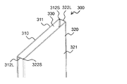
- FIG. 9 is a perspective view of the slot liner 300 of the second embodiment
- FIG. 10 is a perspective view of the slot liner 300 on which the stator coil 138 is mounted.
- differences from the above-described first embodiment will be mainly described, members having the same structure and function will be denoted by the same reference numerals, and description thereof will be omitted.
- the slot liner 300 of the second embodiment has two coil insertion holes 330, and a plurality of (four in the illustrated example) stator coils 138 are arranged in one coil insertion hole 330.
- the slot liner 300 of the second embodiment includes a first insulating member 310 having a first protruding portion 312 and a second insulating member 320 having a second protruding portion 322.
- the first insulating member 310 and the second insulating member are included. In combination with 320, an even number (two in the figure) of coil insertion holes 330 is formed.
- the first insulating member 310 includes a plate-shaped first base portion 311 arranged along the inner wall of the slot 420, and three first long protruding portions 312L vertically protruding from the first base portion 311 in the circumferential direction. Composed.
- the second insulating member 320 includes a plate-shaped second base portion 321 arranged along the inner wall of the slot 420, and three second long protruding portions 322L vertically protruding from the second base portion 321 in the circumferential direction. Composed.
- the first long protrusion 312L and the second long protrusion 322L are in contact with each other at the side surfaces (the surfaces extending in the circumferential direction and facing each other in the radial direction) over most of the circumferential width of the slot 420. That is, in the second embodiment, the first insulating member 310 and the second insulating member 320 have the same shape, and by combining two parts having the same shape as the first insulating member 310 and the second insulating member 320, the slot liner 300 is formed.
- a stopper portion 313 protruding laterally is provided on the upper outside of the first insulating member 310 and the second insulating member 320. Good.
- the slot liner 300 can be configured by combining the first insulating member 310 and the second insulating member 320, the cost of parts can be reduced.
- FIG. 11 is an axial view of the slot liner 300 of Modification 1 mounted in the slot 420
- FIG. 12 is an enlarged view of part of FIG. 11.
- the plurality of first protrusions 312 vertically protruding in the circumferential direction from the first base 311 are configured by three first long protrusions 312L.
- the second protruding portion 322 that vertically protrudes from the second base portion 321 in the circumferential direction is composed of three second long protruding portions 322L.
- the first long protrusion 312L and the second long protrusion 322L, which are arranged at opposite positions, are in contact with each other at a side surface (a surface extending in the circumferential direction and facing in the radial direction).
- the slot liner 300 is formed by combining the first insulating member 310 and the second insulating member 320 having the same shape.
- FIG. 13 is an axial view of the slot liner 300 of Modification 2 mounted in the slot 420
- FIG. 14 is an enlarged view of part of FIG. 13.
- the plurality of first protrusions 312 vertically protruding in the circumferential direction from the first base 311 are composed of three first long protrusions 312L.
- the second protruding portion 322 that vertically protrudes from the second base portion 321 in the circumferential direction is composed of three second short protruding portions 322S.
- the first long projecting portion 312L and the second short projecting portion 322S that are arranged at the opposite positions are in contact with each other at the side surface (the surface that extends in the circumferential direction and face each other in the radial direction), and are arranged at the opposite positions.
- the formed first short protruding portion 312S and the second long protruding portion 322L are in contact with each other at a side surface (a surface extending in the circumferential direction and facing in the radial direction).
- the slot liner 300 is formed by combining the first insulating member 310 and the second insulating member 320 having different shapes.
- the insulator is not provided between the stator coils 138 of the same phase, and the stator coils 138 of the different phases are provided. Since the insulator is provided in the coil, the space factor of the coil can be improved without sacrificing the insulating property.
- FIG. 15 is a perspective view of the slot liner 300 of the third embodiment
- FIG. 16 is a perspective view of the slot liner 300 on which the stator coil 138 is mounted.
- differences from the above-described embodiments will be mainly described, members having the same structure and function will be denoted by the same reference numerals, and description thereof will be omitted.
- the slot liner 300 of the third embodiment forms one coil insertion hole 330, and a plurality of (eight in the illustrated example) stator coils 138 are arranged in one coil insertion hole 330.
- the slot liner 300 of the third embodiment includes a first insulating member 310 having a first protruding portion 312 and a second insulating member 320 having a second protruding portion 322, and the first insulating member 310 and the second insulating member. By combining with 320, one coil insertion hole 330 is formed.
- the insulation between the plurality of stator coils 138 mounted in one coil insertion hole 330 depends on the coating of the electric wires that form the coil, so the plurality of stator coils 138 mounted in one coil insertion hole 330 It is recommended that the currents flowing in the same phase be in phase.
- the first insulating member 310 includes a plate-shaped first base portion 311 arranged along the inner wall of the slot 420, and one first long protruding portion vertically protruding in the circumferential direction from an end portion of the first base portion 311. 312L and one first short protruding portion 312S that vertically protrudes from the other end of the first base portion 311 in the circumferential direction.
- the second insulating member 320 includes a plate-shaped second base 321 arranged along the inner wall of the slot 420, and a second second base 321 vertically protruding from the end of the second base 321 in the circumferential direction.
- the long protrusion 322L and one second short protrusion 322S vertically protruding in the circumferential direction from the other end of the second base 321 are included.
- the first long projecting portion 312L and the second short projecting portion 322S that are arranged at opposite positions are in contact with each other at the side surface (the surface that extends in the circumferential direction and face each other in the radial direction), and are arranged at the opposite positions.
- the formed first short protruding portion 312S and the second long protruding portion 322L are in contact with each other at a side surface (a surface extending in the circumferential direction and facing in the radial direction).
- the first insulating member 310 and the second insulating member 320 have the same shape, and by combining two parts having the same shape as the first insulating member 310 and the second insulating member 320, the slot liner 300 is formed. Form.
- a stopper portion 313 protruding laterally may be provided on the upper outside of the first insulating member 310 and the second insulating member 320.
- FIG. 17 is a view of a modified slot liner 300 mounted in the slot 420 as seen from the axial direction
- FIG. 18 is a partially enlarged view of FIG.
- the first insulating member 310 includes a plate-shaped first base 311 arranged along the inner wall of the slot 420, and two first bases 311 vertically projecting from the first base 311 in the circumferential direction. It is configured with the first long protrusion 312L.
- the second insulating member 320 includes a plate-shaped second base portion 321 arranged along the inner wall of the slot 420, and two second short protruding portions 322S vertically protruding from the second base portion 321 in the circumferential direction. Composed.
- the first long protrusion 312L and the second long protrusion 322L are in contact with each other at a side surface (a surface extending in the circumferential direction and facing in the radial direction).
- the space factor of the coil is reduced. Can be improved.
- FIGS. 19 and 20 are axial views of the slot liner 300 of the fourth embodiment mounted in the slot 420
- FIG. 20 is a partially enlarged view of FIG.
- differences from the above-described embodiment will be mainly described, members having the same structure and function will be denoted by the same reference numerals, and description thereof will be omitted.
- the slot liner 300 of the fourth embodiment has a plurality of coil insertion holes 330, and one stator coil 138 is arranged in one coil insertion hole 330.
- the slot liner 300 according to the fourth embodiment includes a first insulating member 310 having a first long protrusion 312L and a second insulating member 320 having a second short protrusion 322S. By combining with the insulating member 320, an even number (eight in the figure) of coil insertion holes 330 is formed.
- all the first protrusions 312 of the first insulating member 310 are the first long protrusions 312L
- all the second protrusions 322 of the second insulating member 320 are the second short protrusions 322S. ..
- the first insulating member 310 includes a plate-shaped first base 311 arranged along the inner wall of the slot 420, and a plurality of first insulating members 310 vertically projecting from the first base 311 in the circumferential direction. 9) first long protrusions 312L.
- the second insulating member 320 includes a plate-shaped second base portion 321 arranged along the inner wall of the slot 420, and a plurality of (nine in the figure) second short portions vertically projecting from the second base portion 321 in the circumferential direction. And a protrusion 322S.
- the first long protruding portion 312L and the second short protruding portion 322S which are arranged at opposite positions, are in contact with each other at a side surface (a surface extending in the circumferential direction and facing in the radial direction).
- the length of some of the second short protrusions 322S may be increased to form the second long protrusions 322L.
- two insulators of the first long protrusion 312L and the second long protrusion 322L are arranged between the adjacent stator coils 138. The insulation between the child coils 138 can be improved, and sufficient insulation can be ensured between the coils even when currents of different phases are passed.
- a stopper portion 313 protruding laterally may be provided on the upper outside of the first insulating member 310 and the second insulating member 320.
- the first insulating member 310 is provided with the first long protrusion 312L and the second insulating member 320 is provided with the second short protrusion 322S. Since the protruding portions provided on the insulating member have the same length, it is possible to suppress warping of the insulating members 310 and 320. For this reason, when the first insulating member 310 and the second insulating member 320 are arranged in the slot 420, the coil insertion hole 330 does not become narrow, and the deterioration of the insertability of the stator coil 138 can be suppressed and the workability is improved. it can.
- FIGS. 21 and 22 are axial views of the slot liner 300 of the fifth embodiment mounted in the slot 420
- FIG. 22 is a partially enlarged view of FIG.
- differences from the above-described embodiment will be mainly described, members having the same structure and function will be denoted by the same reference numerals, and description thereof will be omitted.
- the slot liner 300 of the fifth embodiment has a plurality of coil insertion holes 330, and one stator coil 138 is arranged in one coil insertion hole 330.
- the slot liner 300 according to the fifth embodiment includes a first insulating member 310 having a first long protruding portion 312L and a second insulating member 320 having a second long protruding portion 322L. By combining with the insulating member 320, an even number (eight in the figure) of coil insertion holes 330 is formed.
- all the first protrusions 312 of the first insulating member 310 are the first long protrusions 312L
- all the second protrusions 322 of the second insulating member 320 are the second long protrusions 322L. ..
- the first insulating member 310 includes a plate-shaped first base portion 311 arranged along an inner wall of the slot 420, and a plurality of first insulating members 310 vertically projecting from the first base portion 311 in the circumferential direction (in the figure, 9) first long protrusions 312L.
- the second insulating member 320 includes a plate-shaped second base 321 arranged along the inner wall of the slot 420, and a plurality of (nine in the figure) second lengths that vertically project from the second base 321 in the circumferential direction. It is composed of a protrusion 322L.
- the first long protrusion 312L and the second long protrusion 322L which are arranged at opposite positions, are in contact with each other at a side surface (a surface extending in the circumferential direction and facing in the radial direction).
- one stator coil 138 is arranged in one coil insertion hole 330, and the first long protrusion 312L and the second long protrusion 322L are provided between the adjacent stator coils 138. Since the two insulators are arranged, the insulation between the adjacent stator coils 138 can be improved, and sufficient insulation can be ensured between the coils even when currents of different phases are passed.
- the length of a part of the second long protrusion 322L may be shortened to form the second short protrusion 322S.
- two insulators of the first long protrusion 312L and the second long protrusion 322L are arranged between the adjacent stator coils 138. The insulation between the child coils 138 can be improved, and sufficient insulation can be ensured between the coils even when currents of different phases are passed.
- the insulator by the first long protruding portion 312L is arranged between the adjacent stator coils 138, so that the stator coil 138 inside the slot 420 is Area (space factor) can be improved.
- a stopper portion 313 protruding laterally may be provided on the upper outside of the first insulating member 310 and the second insulating member 320.
- the two insulators of the first long protrusion 312L and the second long protrusion 322L are arranged between the adjacent stator coils 138.
- the insulation between the adjacent stator coils 138 can be improved.
- the width (circumferential size) of the stator coil 138 is different, and the same insulating member is used even if the width of the slot 420 is wide. Can be used.
- the width (size in the circumferential direction) of the stator coil 138 is small and the width of the slot 420 is narrow, the first long protrusion 312L and the second long protrusion 322L arranged between the stator coils 138 are arranged. Since it has a large overlap with, the insulation performance can be improved.
- the long protruding portions 312L and 322L and the short protruding portions 312S and 322S are various other than those illustrated. Arrangement of various patterns is conceivable. A modified example of the arrangement of the long protrusions 312L and 322L and the short protrusions 312S and 322S will be described below.
- stator coil 138 is wound.
- a predetermined number may be even. That is, the number of the coil insertion holes 330 varies depending on the winding form of the stator coil 138, and may be 8, 4, 2, 1, or an even number exceeding 8.
- All the first protrusions 312 of the first insulating member 310 may be first long protrusions 312L having a length that reaches the second base portion 321 of the second insulating member 320, and some of the first protrusions 312 may be included.
- the first long protrusion 312L may be used.
- all the first protrusions 312 of the second insulating member 320 may be the second long protrusions 322L having a length that reaches the first base 311 of the first insulating member 310, and some of the second protrusions. 322 may be the second long protrusion 322L.
- the overlap length at which the first long protrusion 312L and the second long protrusion 322L contact each other May be part of the length of slot 420 or full width. That is, the length of the first long protrusion 312L and the second long protrusion 322L may be substantially the same as the width of the slot 420 (the length in the radial direction) or shorter than the width of the slot 420.
- the lengths of the plurality of first long protrusions 312L may be the same or different. Further, the lengths of the plurality of second long protrusions 322L may be the same or different. The length of the first long protrusion 312L and the length of the second long protrusion 322L may be the same or different.
- the first long protruding portion 312 When a part of the first protruding portion 312 is the first long protruding portion 312L, the first long protruding portion 312L and the first short protruding portion 312L and the first short protruding portion 312L are continuously provided on the outer peripheral side or the inner peripheral side.
- the protrusions 312S may be provided in a mixed manner (for example, the first long protrusions 312L and the first short protrusions 312S may be alternately provided).
- the second projecting portion 322 when a part of the second projecting portion 322 is the second long projecting portion 322L, even if the second long projecting portion 322L is continuously provided on the outer peripheral side or the inner peripheral side, the second long projecting portion 322L is not provided.
- the second short protrusions 322S may be mixed (for example, the first long protrusions 312L and the first short protrusions 312S may be alternately provided).
- the second protrusion 322 provided at a position corresponding to the first long protrusion 312L may be the second long protrusion 322L or the second short protrusion 322S.
- the second projecting portion 322 provided at a position corresponding to the second long projecting portion 322L becomes the second long projecting portion 322L.
- FIGS. 23, 24, 25 and 26 23 is a perspective view of the slot liner 300 of the sixth embodiment
- FIG. 24 is a perspective view of the slot liner 300 in which the stator coil 138 is mounted
- FIG. 25 is an axial view of the slot liner 300 in which the slot 420 is mounted
- FIG. 26 is a view seen from the direction
- FIG. 26 is an enlarged view of a part of FIG. 25.
- differences from the above-described embodiments will be mainly described, members having the same structure and function are designated by the same reference numerals, and description thereof will be omitted.
- the slot liner 300 of the sixth embodiment has a plurality of coil insertion holes 330, and one stator coil 138 is arranged in one coil insertion hole 330.
- the slot liner 300 of the sixth embodiment includes a first insulating member 310 having a first protruding portion 312 and a second insulating member 320 having a second protruding portion 322, and the first insulating member 310 and the second insulating member. In combination with 320, an even number (eight in the figure) of coil insertion holes 330 is formed.
- the innermost first long protrusion 312L of the first insulating member 310 is thick, that is, a large protrusion 340 having a large radial size.
- the thick protrusion 340 may be formed by the innermost long protrusions 312L and 322L, and thus may be provided on either the first insulating member 310 or the second insulating member 320. It may be provided on both of the two insulating members 320.
- the stator coil 138 is arranged closer to the outer peripheral side in the slot 420, so that the eddy current flowing in the stator core 132 can be reduced and the rotating electric machine 100 can be reduced. The efficiency of can be improved.
- FIGS. 27, 28 and 29 are cross-sectional views of the slot liner 300 in which the first insulating member 310 and the second insulating member 320 are combined
- FIG. 28 is a diagram showing the slot liner 300 when the stator coil 138 is inserted
- 29 is a view showing the slot liner 300 after the stator coil 138 is inserted.
- differences from the above-described first embodiment will be mainly described, members having the same structure and function will be denoted by the same reference numerals, and description thereof will be omitted.
- the slot liner 300 of the seventh embodiment has a plurality of coil insertion holes 330, and one stator coil 138 is arranged in one coil insertion hole 330.
- the narrow mouth portion 331 is provided inside the coil insertion hole 330.
- the narrow mouth portion 331 may be provided inside the slot liner 300, but in the case of a structure in which two segment coils are connected inside the slot 420, the narrow mouth portion 331 has a narrow length in a predetermined axial direction including the connection position.
- the portion 331 may be provided.
- the direction of the coil insertion hole 330 is directed to one or more of these walls. It is advisable to form the narrow mouth portion 331 by providing a convex portion projecting to the side by resin molding. It should be noted that the convex portion forming the narrow mouth portion 331 may be provided on both opposing surfaces (for example, the set of the first base 311 and the second base 321, the set of the protrusions 312, 322), but one surface It may be provided only in.
- the position of the stator coil 138 can be easily determined, and the deviation of the stator coil 138 before injecting the varnish can be suppressed. it can.
- the insulating members are combined with each other to form the rectangle (coil insertion hole 330) for coil insertion.
- the second insulating member 320 is arranged side by side along the radial direction with the plate-shaped first base portion 311 arranged along the inner wall of the accommodation space (slot 420).
- the second insulating member 320 has a plurality of first protruding portions 312 protruding from the first base portion 311 toward the second insulating member 320, and the second insulating member 320 is a plate-shaped second base portion arranged along the inner wall of the slot 420.
- the first protrusion 312 and the second protrusion 322 are provided. Since it is in contact with 322 on the surface extending in the circumferential direction, it is possible to eliminate the gap of the insulator made of resin between the stator coils 138 and between the stator coil 138 and the inner wall of the slot 420, thereby improving the insulation property. it can. Further, the slot liner 300 can be prevented from being deformed in the slot 420, and the stator coil 138 can be easily mounted on the stator core 132.
- the plurality of first protrusions 312 include at least one of the first long protrusion 312L and the first short protrusion 312S shorter than the first long protrusion 312L, and the plurality of second protrusions 322 are At least one of the second long protrusion 322L and the second short protrusion 322S shorter than the second long protrusion 322L is included, and the second long protrusion 322L or the second long protrusion 322L is provided at a position facing the first long protrusion 312L.
- the short protruding portion 322S is arranged and the second long protruding portion 322L is arranged at a position facing the first short protruding portion 312S, two parts having the same shape (the first insulating member 310 and the second insulating member). 320) can be combined to form the slot liner 300, and the cost of parts can be reduced.
- the stator coils 138 are separated from each other by the two insulators of the first long protruding portion 312L and the second long protruding portion 322L, the insulation between the coils can be improved at that portion, and even between the coils of different phases. Sufficient insulation can be secured.
- the first protrusion 312 is the first long protrusion 312L
- the second protrusion 322 is the second short protrusion 322S
- the length of the first long protrusion 312L is the same as that of the first insulating member 310.
- the coil insertion hole 330 does not become narrow, and the deterioration of the insertability of the stator coil 138 can be suppressed and the workability can be improved. ..
- first insulating member 310 and the second insulating member 320 have the same shape, and the first insulating member 310 and the second insulating member 320 are symmetrically arranged and combined to form a rectangle for coil insertion (coil insertion Since the insulating member (slot liner 300) having the hole 330) is configured, the slot liner 300 can be configured by combining two parts (first insulating member 310, second insulating member 320) of the same shape, and the cost of the part Can be reduced.
- N is a positive integer (for example, 9)
- 2N-1 first long protrusions 312L are arranged side by side from the one end side (outer peripheral side) and the other end side (inner peripheral side) in the first base 311.
- 2N-1 second short protrusions 322L are arranged side by side from the other end side (inner circumference side) to the second base 321 and one short side end (outer circumference).
- 2N second short protrusions 322S are arranged side by side from the side), and the 2N ⁇ 1th first long protrusion 312L from the one end side (outer peripheral side) of the first base 311 and the other end side (inside) of the second base 321
- the second long protrusion 322L which is the 2N ⁇ 1th position from the circumferential side), comes into contact with the surface extending in the circumferential direction, so that the space factor of the stator coil 138 is not lowered and the second coil is fixed at that position.
- the insulation between the child coils 138 can be improved.
- first protruding portion 312 and the second protruding portion 322 have the same length, and the first protruding portion 312 has a length in which the first insulating member 310 and the second insulating member 320 are insulating members (slot liner 300). ), the surface extending in the circumferential direction has a length that allows contact with the second projecting portion 322, so that the insulation between the adjacent stator coils 138 can be improved by the two insulators. .. Further, even if the width (size in the circumferential direction) of the stator coil 138 is different and the width of the slot 420 is wide, the same insulating member can be used.
- a step is provided on at least one outer surface of the first base 311 and the second base 321, Since the stopper portion 313 is configured and the stopper portion 313 and the axial end surface of the stator core 132 contact each other, the slot liner 300 can be accurately positioned on the stator core 132 when the slot liner 300 is inserted into the slot 420. .. Further, even when the stator coil 138 is inserted into the slot 420, the axial position of the slot liner 300 in the stator core 132 can be maintained, and the displacement of the slot liner 300 can be prevented.
- At least one of the innermost first protrusion portion 312 of the first insulating member 310 and the innermost second protrusion portion 322 of the second insulating member 320 is provided to the other first protruding portions 312 and Since the radial direction is larger than that of the second projecting portion 322, the stator coil 138 is arranged closer to the outer peripheral side in the slot 420, so that the eddy current flowing in the stator core 132 can be reduced and the efficiency of the rotating electric machine 100 can be improved. Can be improved.
- At least one of the first base portion 311, the first protruding portion 312, the second base portion 321, and the second protruding portion 322 is provided with a convex portion that protrudes inward of the rectangular shape for inserting the coil, and has a narrow mouth portion. Since 331 is configured, the position of the stator coil 138 can be easily determined, and the deviation of the stator coil 138 before injecting the varnish can be suppressed. In particular, it is possible to prevent the coil from being displaced when the conductor wire is bent on the welding side of the stator coil 138 in a later step. Further, it is possible to suppress the movement of the connecting portion of the two segment coils connected inside the slot 420, and to suppress the conduction failure.
- the above description is merely an example, and when interpreting the invention, there is no limitation or restriction on the correspondence between the items described in the above embodiment and the items described in the claims.
- the rotating electric machine in which the rotor is provided with the permanent magnet has been described as an example, but the present invention can be similarly applied to the stator of the rotating electric machine such as an induction motor. Further, the present invention can be applied to other than a vehicle driving rotating electric machine.
- the present invention is not limited to the above-described embodiments, but includes various modifications and equivalent configurations within the spirit of the appended claims.
- the above-described embodiments have been described in detail in order to explain the present invention in an easy-to-understand manner, and the present invention is not necessarily limited to those having all the configurations described.
- part of the configuration of one embodiment may be replaced with the configuration of another embodiment.
- the configuration of another embodiment may be added to the configuration of one embodiment.
- a part of the configuration of each embodiment may be added/deleted/replaced with another configuration.
Landscapes
- Engineering & Computer Science (AREA)
- Power Engineering (AREA)
- Insulation, Fastening Of Motor, Generator Windings (AREA)
Abstract
本発明の課題は、コイル間の絶縁性能が高く、製造が容易な固定子を提供することである。 回転電機の固定子であって、コイルと、前記コイルと接する絶縁部材と、前記コイル及び前記絶縁部材の収容空間を形成するコア部と、を備え、前記絶縁部材は、互いに組み合わされてコイル挿入用の矩形を形成する第1絶縁部材及び第2絶縁部材によって構成され、前記第1絶縁部材は、前記収容空間の内壁に沿って配置される板状の第1基部と、径方向に沿って並んで配置され、前記第1基部から前記第2絶縁部材に向けて突出する複数の第1突出部とを有し、前記第2絶縁部材は、前記収容空間の内壁に沿って配置される板状の第2基部と、径方向に沿って並んで配置され、前記第2基部から前記第1絶縁部材に向けて突出する複数の第2突出部とを有し、前記第1突出部と前記第2突出部とは周方向に延在する面で接触する。
Description
本発明は、回転電機の固定子に関する。
回転電機は高出力が求められており、固定子を構成する電磁鋼板の積層圧を大きくし、コイルを高ターン化することが望まれている。また、固定子コア内に配置されるコイルの導線は、その固定や絶縁のために紙で構成されるスロットライナーによって覆われている。
本技術分野の背景技術として、以下の先行技術がある。特許文献1(特開2013-208033号)には、周方向に複数のスロットが設けられた電機子鉄心と、スロットに挿入され電機子鉄心に巻回された電機子巻線と、電機子鉄心と電機子巻線とを絶縁するインシュレータを備え、インシュレータは、スロットの深さに対応した幅を有する絶縁板材を折り曲げて形成した第1の折り曲げ絶縁体と、これと同等形状の第2の折り曲げ絶縁体を組み合わせて形成され、この組み合わせのためにスリットを形成し、各スリット同士を嵌め合わせることでスロットの深さに対応した幅を有しかつスロット内でこれら絶縁体が協働してスロットに挿入する隣接する電線同士互いに絶縁して挿入する電線個別収容空間をスロットに挿入する電線の本数に合わせて形成している。
しかし、固定子の積層圧が大きくなると、固定子コアに設けられるスロットが長くなり、コイル導線が長くなる。また、コイルが高ターン化すると、一つのスロットに多数の導線が挿入される。このため、スロットにコイルを挿入する際に、コイル導線が変形し、回転電機の性能が低下する可能性がある。また、スロットライナーの装着後にコイルを挿入する際に、スロットライナーが変形し、コイル導線間の絶縁性能が低下する可能性がある。
また、特許文献1に記載されたインシュレータは、二つの絶縁体を組み立てて構成されているものの、前述した課題を解決するものではない。
このため、スロット内でのコイル導線やスロットライナーの変形を防止し、コイル間の絶縁性能が高く、製造が容易な固定子コアが求められている。
本願において開示される発明の代表的な一例を示せば以下の通りである。すなわち、回転電機の固定子であって、コイルと、前記コイルと接する絶縁部材と、前記コイル及び前記絶縁部材の収容空間を形成するコア部と、を備え、前記絶縁部材は、互いに組み合わされてコイル挿入用の矩形を形成する第1絶縁部材及び第2絶縁部材によって構成され、前記第1絶縁部材は、前記収容空間の内壁に沿って配置される板状の第1基部と、径方向に沿って並んで配置され、前記第1基部から前記第2絶縁部材に向けて突出する複数の第1突出部とを有し、前記第2絶縁部材は、前記収容空間の内壁に沿って配置される板状の第2基部と、径方向に沿って並んで配置され、前記第2基部から前記第1絶縁部材に向けて突出する複数の第2突出部とを有し、前記第1突出部と前記第2突出部とは周方向に延在する面で接触することを特徴とする。
本発明によれば、コイル間の絶縁性能が高く、製造が容易な固定子を提供できる。前述した以外の課題、構成及び効果は、以下の実施例の説明によって明らかにされる。
以下、図面を参照して本発明の実施例を説明する。
<回転電機の全体構成>
本実施形態に係る回転電機は、自動車の走行への使用が好適な回転電機である。ここで、回転電機を使用するいわゆる電気自動車には、エンジンと回転電機の両方を備えるハイブリッドタイプの電気自動車(HEV)と、エンジンを用いないで回転電機のみで走行する純粋な電気自動車(EV)とがあるが、以下に説明する回転電機は両方のタイプに利用できる。
本実施形態に係る回転電機は、自動車の走行への使用が好適な回転電機である。ここで、回転電機を使用するいわゆる電気自動車には、エンジンと回転電機の両方を備えるハイブリッドタイプの電気自動車(HEV)と、エンジンを用いないで回転電機のみで走行する純粋な電気自動車(EV)とがあるが、以下に説明する回転電機は両方のタイプに利用できる。
図1は、本発明の実施例にかかる回転電機100の全体構成を示す模式図である。図1では、回転電機100の一部分を断面として、回転電機100の内部を示している。回転電機100は、ケース10の内部に配設され、ハウジング112と、ハウジング112に固定される固定子コア132を有する固定子130と、固定子130内に回転自在に配設される回転子150とを有する。ケース10は、エンジンのケースや変速機のケースによって構成されてもよい。
この回転電機100は、永久磁石内蔵型の三相同期モータである。本実施例では、回転電機100の例として三相同期モータについて説明するが、本発明は誘導モータにも適用できる。
本実施例の回転電機100は、固定子コア132に巻回される固定子コイル138に三相交流電流が供給されることで、回転子150を回転させる電動機として作動する。また、回転電機100は、エンジンによって駆動されると、発電機として作動して三相交流の発電電力を出力する。つまり、回転電機100は、電気エネルギーに基づいて回転トルクを発生する電動機としての機能と、機械エネルギーに基づいて発電する発電機としての機能の両方を有しており、自動車の走行状態によって前述した機能を選択的に利用できる。
固定子130はハウジング112に固定されている。固定子130は、ハウジング112に設けられたフランジ115がボルト12によりケース10に締結されることによって、ケース10内に固定され、保持されている。回転軸118に固定された回転子150は、ケース10の軸受け14A、14Bにより支承され、固定子コア132の内側において回転可能に保持される。
図2は、ハウジング112に取り付けられた固定子130を示す斜視図であり、図3は固定子コア132の斜視図である。ハウジング112は、厚さ2~5mm程度の鋼板(高張力鋼板など)を絞り加工によって円筒形状に形成されている。ハウジング112の軸方向一端にはフランジ115が設けられており、前述したようにケース10にボルトで固定される(図1参照)。フランジ115は、絞り加工によってハウジング112と一体に形成される。なお、ハウジング112を設けずに、固定子130をケース10に直接固定してもよい。
固定子130は、ハウジング112の内周側に固定され、円筒状の固定子コア132と、固定子コア132に装着される固定子コイル138とを有している。固定子コア132は、例えば、厚さが0.05~1.0mm程度の打ち抜き加工又はエッチング加工によって成形された複数の電磁鋼板133を積層して形成される。積層された電磁鋼板133は溶接によって接続されて、固定され、ハウジング112に圧入した際の締め付け力に起因する電磁鋼板133の変形が抑制される。
固定子コア132には、軸方向に延在する複数のスロット420が周方向に等間隔となるように形成されている。スロット420の数は、例えば本実施の形態では72個である。スロット420には、図2に示すように固定子コイル138が収容される。図3に示す例では、スロット420は開スロットであり、固定子コア132の内周側には開口が形成されている。この開口の周方向の幅は、固定子コイル138が装着される各スロット420のコイル装着部とほぼ同等又はコイル装着部よりも若干小さいとよい。
なお、各スロット420内には、スロットライナー300が配置されている。スロットライナー300は、例えば耐熱性を有する樹脂で所定の形状に成形されており、厚さは0.1~0.5mm程である。スロットライナー300は、スロット420やコイルエンド140a、140bに配設される。スロットライナー300をスロット420に挿通されるコイルの相互間、及びコイルとスロット420の内面との間に配設され、絶縁部材として機能して、コイル間やコイルとスロット420の内面との間の絶縁耐圧を向上している。
固定子コイル138は、U字形状の複数のセグメントコイル28が互いに接続されて形成される。セグメントコイル28は、その端部がスロット420(すなわち固定子130)から露出するように、一つの端部が他のセグメントコイル28と隣接するように配置され、他方の端部がさらに他のセグメントコイル28と隣接して配置されている。端部が隣接するセグメントコイル28は、その隣接する端部において互いに接続されることによって、固定子コア132に巻回される固定子コイル138を形成している。本実施例において、セグメントコイル28は、スロット420から露出した端部が溶接によって接続されるタイプの他、固定子コア132の両側から挿入されたセグメントコイルがスロット420内部で接続されるタイプでもよい(図28、図29参照)。
また、コイルエンド140a、140bに配設されるスロットライナー300は、コイルエンド140a、140bにおける相間絶縁や導体間絶縁のためにコイル間に環状に配設される。このように、本実施例の回転電機100では、スロット420の内側やコイルエンド140a、140bにスロットライナー300が配設されているため、コイルの絶縁被膜が傷ついたり劣化したりしても、必要な絶縁耐圧を保持できる。
スロット420間にはティース430が形成されており、各ティース430は環状のコアバック440と一体に成形されている。固定子コア132は、各ティース430とコアバック440とが一体に成形された一体型コアとされている。ティース430は、固定子コイル138によって発生した回転磁界を回転子150に導き、回転子150に回転トルクを発生させる。
回転子150は、回転子鉄心152と、回転子鉄心152に形成された磁石挿入孔に保持されている永久磁石154とを有している。
回転子鉄心152には、直方体形状の磁石挿入孔が外周部近傍において周方向に等間隔で形成されている。各磁石挿入孔には永久磁石154が埋め込まれ、接着剤などで固定されている。磁石挿入孔の円周方向の幅は、永久磁石154の円周方向の幅よりも大きく形成されており、永久磁石154の両側には磁気的空隙156が形成されている。この磁気的空隙156は接着剤を埋め込んでもよいし,樹脂で永久磁石154と一体に固めてもよい。
永久磁石154は、回転子150の界磁極を形成するものである。なお、本実施例では、一つの永久磁石154で一つの磁極を形成する構成としているが、一つの磁極を複数の永久磁石によって構成してもよい。各磁極を形成するための永久磁石を複数に増やすことで、永久磁石が発する各磁極の磁束密度が大きくなり、磁石トルクを増大することができる。永久磁石154には、ネオジウム系、サマリウム系の焼結磁石やフェライト磁石、ネオジウム系のボンド磁石などを用いることができるが、永久磁石154の残留磁束密度は、0.4~1.3T程度が望ましく、ネオジウム系の磁石がより適している。各永久磁石154間に補助磁極が形成されてもよい。
三相交流電流が固定子コイル138に供給されることにより固定子130に回転磁界が発生すると、この回転磁界が回転子150の永久磁石154に作用して磁石トルクが発生する。回転子150には、この磁石トルクに加えて、上述のリラクタンストルクが発生するので、回転子150には上述の磁石トルクとリラクタンストルクとの両方のトルクが回転トルクとして作用し、大きな回転トルクを得ることができる。
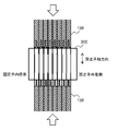
本発明の固定子130のスロットライナー300は、以下に説明する各実施例で図示するように、複数の第1突出部を有する第1絶縁部材と複数の第2突出部を有する第2絶縁部材とが組み合わされて、軸方向から見て梯子状の断面を有する絶縁体が形成される。第1突出部と第2突出部とは、その断面ではなく側面(周方向に延在し、径方向で相対する面)で接触して、複数個の矩形のコイル挿入穴330が形成される。このように、本発明の固定子130のスロットライナー300は、いわば、お菓子の最中の皮のように中空部(中空部には餡ではなく固定子コイル138が挿入される)を形成するモナカ構造となっている。以下、各実施例のスロットライナー300の形状について詳しく説明する。
<実施例1>
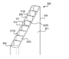
図4、図5、図6、図7及び図8を参照して実施例1のスロットライナー300について説明する。図4は実施例1のスロットライナー300の斜視図であり、図5は固定子コイル138が実装されたスロットライナー300の斜視図であり、図6はスロットライナー300が実装された固定子コア132を軸方向から見た図であり、図7はスロット420に実装されたスロットライナー300を軸方向から見た図であり、図8は図7の一部の拡大図である。
図4、図5、図6、図7及び図8を参照して実施例1のスロットライナー300について説明する。図4は実施例1のスロットライナー300の斜視図であり、図5は固定子コイル138が実装されたスロットライナー300の斜視図であり、図6はスロットライナー300が実装された固定子コア132を軸方向から見た図であり、図7はスロット420に実装されたスロットライナー300を軸方向から見た図であり、図8は図7の一部の拡大図である。
実施例1のスロットライナー300は複数個の矩形のコイル挿入穴330を形成し、一つのコイル挿入穴330に1本の固定子コイル138が配置される。実施例1のスロットライナー300は、第1突出部312を有する第1絶縁部材310と、第2突出部322を有する第2絶縁部材320とで構成され、第1絶縁部材310と第2絶縁部材320とを組み合わせて偶数個(図では8個)のコイル挿入穴330が形成される。実施例1では、一つのコイル挿入穴330に1本の固定子コイル138が配置される。
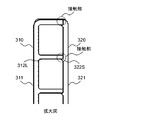
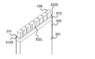
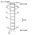
図7に示すように、第1絶縁部材310は、スロット420の内壁に沿うように配置される板状の第1基部311と、第1基部311から垂直に周方向に突出する複数の第1突出部312で構成される。複数の第1突出部312は、5個の第1長突出部312Lと4個の第1短突出部312Sとで構成される。第1長突出部312Lは、第1基部からの突出長が第1短突出部312Sより長い。同様に、第2絶縁部材320は、スロット420の内壁に沿うように配置される板状の第2基部321と、第2基部321から垂直に周方向に突出する複数の第2突出部322で構成される。複数の第2突出部322は、5個の第2長突出部322Lと4個の第2短突出部322Sとで構成される。第2長突出部322Lは、第1基部からの突出長が第2短突出部322Sより長い。つまり、実施例1では、第1絶縁部材310と第2絶縁部材320とは同じ形状であり、同じ形状の二つの部品を第1絶縁部材310及び第2絶縁部材320として組み合わせることによって、スロットライナー300が形成される。
外周側から4個の第1長突出部312Lと4個の第2短突出部322Sとは、側面(周方向に延在し、径方向で相対する面)で接触する。また、内周側から4個の第1短突出部312Sと4個の第2長突出部322Lとは、側面(周方向に延在し、径方向で相対する面)で接触する。また、真中(径方向で5番目)の第1突出部312と真中(径方向で5番目)の第2突出部322とは、側面(周方向に延在し、径方向で相対する面)で接触する。このため、径方向に4番目のコイル挿入穴330と5番目のコイル挿入穴330との間(内周側から数えても、外周側から数えても同じ)では、第1長突出部312Lと第2長突出部322Lの2枚の絶縁体によって固定子コイル138が離隔される。複数が並んで配置されたコイル挿入穴330の中央に2枚の絶縁体が配置されるので、当該箇所の両側で異なる相のコイルを配置しても、十分な絶縁性を確保できる。例えば、2枚の絶縁体が配置される中央部の外周側にはU相のコイルを実装し、内周側にはV相のコイルを実装できる。
第1長突出部312Lの厚さ(径方向の大きさ)は、望ましくは0.1~0.5mm程度であるが、隣接する固定子コイル138に流れる電流の相の異同や、固定子コイル138に印加される電圧に応じて厚さを調整してもよい。このように突出部の厚さを設定すると、固定子コイル138の占積率を低下させずに、固定子コイル138の間の絶縁性を向上できる。
なお、2枚の絶縁体が配置される箇所は中央の1箇所以外でもよい。第1絶縁部材310の第1長突出部312Lの数と、第2絶縁部材320の第2長突出部322Lの数とを異ならせて、2枚の絶縁体を中央ではない位置に配置できる。例えば、第1長突出部312Lの数を6個にし、第2長突出部322Lの数を4個にすると、中央から一つずれた箇所に2枚の絶縁体が配置される。
また、第1長突出部312Lの数を4個より多くし、第2長突出部322Lの数を4個より多くして、中央の1箇所以外にも2枚の絶縁体を配置してもよい。例えば、第1長突出部312Lの数を5個にし、第2長突出部322Lの数を5個にすると、中央と両隣の3箇所に2枚の絶縁体が配置される。
このように、2枚の絶縁体が配置される箇所ではコイル間の絶縁性を向上でき、異なる相のコイル間でも十分な絶縁性を確保できる。
また、図4及び図5に示すように、第1絶縁部材310の外側上部に側方に突出するストッパー部313を設けるとよい。ストッパー部313は、その部分において成型金型に凹を設け、第1絶縁部材310の樹脂を厚くして、スロットライナー300として組み立てられた状態における外側側面に段差を設けてストッパー部313を形成する。ストッパー部313によって、スロットライナー300をスロット420に挿入した際に、ストッパー部313による段差が固定子コア132の軸方向の端面と当接することによって、スロットライナー300を固定子コア132に正確に位置決めできる。また、スロット420への固定子コイル138の挿入時にも、固定子コア132におけるスロットライナー300の軸方向の位置を維持し、スロットライナー300のズレを防止できる。ストッパー部313は、第2絶縁部材320に設けてもよいが、第1絶縁部材310と第2絶縁部材320との少なくとも一方に設ければよい。
このような構造の絶縁部材310、320は、成形後に外側(基部311、321側)に反って変形することがある。絶縁部材310、320が反った状態で組み合わせると、第1突出部312と第2突出部322との隙間が生じ、絶縁性能が低下する可能性がある。しかし、本実施例では、第1絶縁部材310と第2絶縁部材320とを組み合わせてスロット420内に収容するので、スロット420の幅によって、第1基部311と第2基部321との距離が決まり、第1突出部312と第2突出部322とが隙間なく側面で接触する。つまり、絶縁部材310、320が反っている場合、スロット420の内部において、第1基部311と第2基部321との距離が定まり、第1突出部312と第2突出部322とが予め定められた長さだけオーバーラップする。そして、コイル挿入穴330に固定子コイル138を挿入することによって、第1基部311及び第2基部321の反りが小さくなり、第1突出部312と第2突出部322とが適切に接触するようになる。このように、樹脂成形によって絶縁部材310、320の反りが生じても、絶縁性能が低下しないスロットライナー300を構成できる。
以上に説明したように、実施例1のスロットライナー300は、第1絶縁部材310と第2絶縁部材320とを組み合わせて構成したので、スロット420内で第1突起部と第2突出部(第1長突出部312Lと第2短突出部322S、第1短突出部312Sと第2長突出部322L)を組み合わせて、該突起部同士を側面で接触させるので、固定子コイル138間や固定子コイル138とスロット420の内壁との間で樹脂による絶縁体の隙間をなくすことができ、絶縁性を向上できる。
換言すると、突起部を端面で接触させる構造では、部品の寸法のバラツキや経年変化によって第1突出部312と第2突出部322との間に隙間が生じることがある。しかし、本実施例の構成では、部品の寸法のバラツキや経年変化によっても第1突出部312と第2突出部322との間に隙間が生じることなく、固定子コイル138の絶縁性を確保できる。
また、梯子状の断面を有するボビン構造の絶縁体を一体で形成し、固定子コイル138間を離隔する突出部312、322の厚さを薄く成型するのは困難であり、成型金型からの取り出しが困難となることがある。しかし、二つの部材を組み合わせて中空部が形成されるモナカ構造の絶縁体を形成することによって、各部材は成型金型からの取り出しが容易な形状となり、積層厚さが厚い固定子コア132に対応する軸方向に長い樹脂成型品を成形できる。特に、突出部312、322の厚みを薄くしても、樹脂成形の絶縁体を容易に製造できる。
また、紙のスロットライナーでは、積層厚さが厚い固定子コア132では、スロット内でスロットライナーが変形することがある、樹脂成型で軸方向に長いスロットライナー300を構成することによって、スロット420内でスロットライナー300の変形を防止でき、固定子コイル138を固定子コア132へ容易に実装できる。
また、同じ形状の二つの部品(第1絶縁部材310、第2絶縁部材320)を組み合わせてスロットライナー300を構成することによって、部品のコストを低減できる。
<実施例2>
次に、図9、図10、図11、図12、図13及び図14を参照して実施例2のスロットライナー300について説明する。図9は実施例2のスロットライナー300の斜視図であり、図10は固定子コイル138が実装されたスロットライナー300の斜視図である。実施例2において、前述した実施例1との相違点を主に説明し、同じ構造及び機能の部材には同じ符号を付し、それらの説明は省略する。
次に、図9、図10、図11、図12、図13及び図14を参照して実施例2のスロットライナー300について説明する。図9は実施例2のスロットライナー300の斜視図であり、図10は固定子コイル138が実装されたスロットライナー300の斜視図である。実施例2において、前述した実施例1との相違点を主に説明し、同じ構造及び機能の部材には同じ符号を付し、それらの説明は省略する。
実施例2のスロットライナー300は二つのコイル挿入穴330を形成し、一つのコイル挿入穴330に複数本(図示した例では4本)の固定子コイル138が配置される。実施例2のスロットライナー300は、第1突出部312を有する第1絶縁部材310と、第2突出部322を有する第2絶縁部材320とで構成され、第1絶縁部材310と第2絶縁部材320とを組み合わせて偶数個(図では2個)のコイル挿入穴330が形成される。一つのコイル挿入穴330に実装される複数本の固定子コイル138の間の絶縁はコイルを構成する電線の被覆によるので、一つのコイル挿入穴330に実装される複数本の固定子コイル138に流れる電流は同相とするとよい。
第1絶縁部材310は、スロット420の内壁に沿うように配置される板状の第1基部311と、第1基部311から垂直に周方向に突出する3個の第1長突出部312Lとで構成される。第2絶縁部材320は、スロット420の内壁に沿うように配置される板状の第2基部321と、第2基部321から垂直に周方向に突出する3個の第2長突出部322Lとで構成される。第1長突出部312Lと第2長突出部322Lとは、スロット420の周方向の幅の大部分にわたって、側面(周方向に延在し、径方向で相対する面)で接触する。つまり、実施例2では、第1絶縁部材310と第2絶縁部材320とは同じ形状であり、同じ形状の二つの部品を第1絶縁部材310及び第2絶縁部材320として組み合わせることによって、スロットライナー300が形成される。
また、図9及び図10に示すように、実施例2においても、実施例1と同様に、第1絶縁部材310及び第2絶縁部材320の外側上部に側方に突出するストッパー部313を設けるとよい。
このように構成すると、前述した第1実施例と同様に、二つのコイル挿入穴330の間に2枚の絶縁体が配置されるので、異相のコイル間で十分な絶縁性を確保できる。また、第1絶縁部材310と第2絶縁部材320とは同じ形状となり、第1絶縁部材310と第2絶縁部材320とを組み合わせてスロットライナー300を構成できるので、部品のコストを低減できる。
次に、実施例2のスロットライナー300の変形例を説明する。
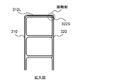
図11はスロット420に実装された変形例1のスロットライナー300を軸方向から見た図であり、図12は図11の一部の拡大図である。
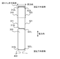
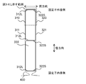
図11に示す変形例1において、第1基部311から垂直に周方向に突出する複数の第1突出部312は、3個の第1長突出部312Lで構成される。第2基部321から垂直に周方向に突出する第2突出部322は、3個の第2長突出部322Lで構成される。相対する位置に配置された第1長突出部312Lと第2長突出部322Lとは、側面(周方向に延在し、径方向で相対する面)で接触する。この変形例1では、同じ形状の第1絶縁部材310と第2絶縁部材320とを組み合わせて、スロットライナー300が形成される。
この変形例1では、スロットライナー300の中央の隣接する固定子コイル138の間に第1長突出部312Lと第2長突出部322Lとの2枚の絶縁体が配置されるので、隣接する固定子コイル138の間の絶縁性を向上でき、異なる相の電流を流してもコイル間で十分な絶縁性を確保できる。また、固定子コイル138とスロット420の内壁の間に第1長突出部312Lと第2長突出部322Lとの2枚の絶縁体が配置されるので、固定子コイル138と固定子コア132の間の絶縁性を向上できる。
図13はスロット420に実装された変形例2のスロットライナー300を軸方向から見た図であり、図14は図13の一部の拡大図である。
図13に示す変形例2において、第1基部311から垂直に周方向に突出する複数の第1突出部312は、3個の第1長突出部312Lで構成される。第2基部321から垂直に周方向に突出する第2突出部322は、3個の第2短突出部322Sで構成される。相対する位置に配置された第1長突出部312Lと第2短突出部322Sとは、側面(周方向に延在し、径方向で相対する面)で接触しており、相対する位置に配置された第1短突出部312Sと第2長突出部322Lとは、側面(周方向に延在し、径方向で相対する面)で接触する。この変形例2では、異なる形状の第1絶縁部材310と第2絶縁部材320とを組み合わせて、スロットライナー300が形成される。
以上に説明したように、実施例2のスロットライナー300は、実施例1で説明した効果に加えて、同相の固定子コイル138の間に絶縁体を設けず、異相の固定子コイル138の間に絶縁体を設けるので、絶縁性を犠牲にすることなく、コイルの占積率を向上できる。
<実施例3>
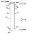
次に、図15、図16、図17及び図18を参照して実施例3のスロットライナー300について説明する。図15は実施例3のスロットライナー300の斜視図であり、図16は固定子コイル138が実装されたスロットライナー300の斜視図である。実施例3において、前述した実施例との相違点を主に説明し、同じ構造及び機能の部材には同じ符号を付し、それらの説明は省略する。
次に、図15、図16、図17及び図18を参照して実施例3のスロットライナー300について説明する。図15は実施例3のスロットライナー300の斜視図であり、図16は固定子コイル138が実装されたスロットライナー300の斜視図である。実施例3において、前述した実施例との相違点を主に説明し、同じ構造及び機能の部材には同じ符号を付し、それらの説明は省略する。
実施例3のスロットライナー300は一つのコイル挿入穴330を形成し、一つのコイル挿入穴330に複数本(図示した例では8本)の固定子コイル138が配置される。実施例3のスロットライナー300は、第1突出部312を有する第1絶縁部材310と、第2突出部322を有する第2絶縁部材320とで構成され、第1絶縁部材310と第2絶縁部材320とを組み合わせて1個のコイル挿入穴330が形成される。1個のコイル挿入穴330に実装される複数本の固定子コイル138の間の絶縁はコイルを構成する電線の被覆によるので、一つのコイル挿入穴330に実装される複数本の固定子コイル138に流れる電流は同相とするとよい。
第1絶縁部材310は、スロット420の内壁に沿うように配置される板状の第1基部311と、第1基部311の端部から垂直に周方向に突出する1個の第1長突出部312Lと、第1基部311の他端部から垂直に周方向に突出する1個の第1短突出部312Sとで構成される。同様に、第2絶縁部材320は、スロット420の内壁に沿うように配置される板状の第2基部321と、第2基部321の端部から垂直に周方向に突出する1個の第2長突出部322Lと、第2基部321の他端部から垂直に周方向に突出する1個の第2短突出部322Sとで構成される。相対する位置に配置された第1長突出部312Lと第2短突出部322Sとは、側面(周方向に延在し、径方向で相対する面)で接触しており、相対する位置に配置された第1短突出部312Sと第2長突出部322Lとは、側面(周方向に延在し、径方向で相対する面)で接触する。実施例3では、第1絶縁部材310と第2絶縁部材320とは同じ形状であり、同一形状の二つの部品を第1絶縁部材310及び第2絶縁部材320として組み合わせることによって、スロットライナー300を形成する。
また、実施例3においても、実施例1、2と同様に、第1絶縁部材310及び第2絶縁部材320の外側上部に側方に突出するストッパー部313を設けてもよい。
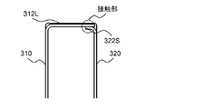
次に、実施例3のスロットライナー300の変形例を説明する。図17はスロット420に実装された変形例のスロットライナー300を軸方向から見た図であり、図18は図17の一部の拡大図である。
図17に示す変形例において、第1絶縁部材310は、スロット420の内壁に沿うように配置される板状の第1基部311と、第1基部311から垂直に周方向に突出する2個の第1長突出部312Lとで構成される。第2絶縁部材320は、スロット420の内壁に沿うように配置される板状の第2基部321と、第2基部321から垂直に周方向に突出する2個の第2短突出部322Sとで構成される。第1長突出部312Lと第2長突出部322Lとは、側面(周方向に延在し、径方向で相対する面)で接触する。
以上に説明したように、実施例3のスロットライナー300は、実施例1、2で説明した効果に加えて、同相の固定子コイル138の間に絶縁体を設けないので、コイルの占積率を向上できる。
<実施例4>
次に、図19及び図20を参照して実施例4のスロットライナー300について説明する。図19はスロット420に実装された実施例4のスロットライナー300を軸方向から見た図であり、図20は図19の一部の拡大図である。実施例4において、前述した実施例との相違点を主に説明し、同じ構造及び機能の部材には同じ符号を付し、それらの説明は省略する。
次に、図19及び図20を参照して実施例4のスロットライナー300について説明する。図19はスロット420に実装された実施例4のスロットライナー300を軸方向から見た図であり、図20は図19の一部の拡大図である。実施例4において、前述した実施例との相違点を主に説明し、同じ構造及び機能の部材には同じ符号を付し、それらの説明は省略する。
実施例4のスロットライナー300は、実施例1と同様に、複数のコイル挿入穴330を形成し、一つのコイル挿入穴330に1本の固定子コイル138が配置される。実施例4のスロットライナー300は、第1長突出部312Lを有する第1絶縁部材310と、第2短突出部322Sを有する第2絶縁部材320とで構成され、第1絶縁部材310と第2絶縁部材320とを組み合わせて偶数個(図では8個)のコイル挿入穴330が形成される。実施例4では、第1絶縁部材310の全ての第1突出部312は第1長突出部312Lであり、第2絶縁部材320の全ての第2突出部322は第2短突出部322Sである。
図19に示すように、第1絶縁部材310は、スロット420の内壁に沿うように配置される板状の第1基部311と、第1基部311から垂直に周方向に突出する複数(図では9個)の第1長突出部312Lとで構成される。第2絶縁部材320は、スロット420の内壁に沿うように配置される板状の第2基部321と、第2基部321から垂直に周方向に突出する複数(図では9個)の第2短突出部322Sとで構成される。相対する位置に配置された第1長突出部312Lと第2短突出部322Sとは、側面(周方向に延在し、径方向で相対する面)で接触する。
実施例4のスロットライナー300は、一つのコイル挿入穴330に1本の固定子コイル138が配置されるので、隣接する固定子コイルに異なる相(例えば、U相とV相)の電流を流しても、良好な絶縁を確保できる。
なお、一部の第2短突出部322Sの長さを長くして第2長突出部322Lとしてもよい。第2長突出部322Lを設けた箇所では、隣接する固定子コイル138の間に第1長突出部312Lと第2長突出部322Lとの2枚の絶縁体が配置されるので、隣接する固定子コイル138の間の絶縁性を向上でき、異なる相の電流を流してもコイル間で十分な絶縁性を確保できる。
また、実施例4においても、実施例1、2と同様に、第1絶縁部材310及び第2絶縁部材320の外側上部に側方に突出するストッパー部313を設けてもよい。
以上に説明したように、実施例4のスロットライナー300は、第1絶縁部材310に第1長突出部312Lを設け、第2絶縁部材320に第2短突出部322Sを設けたので、一つの絶縁部材に設けられる突出部の長さが同じであることから、絶縁部材310、320の反りを抑制できる。このため、第1絶縁部材310及び第2絶縁部材320をスロット420内に配置した際に、コイル挿入穴330が狭くならず、固定子コイル138の挿入性の低下を抑制でき、作業性を向上できる。
<実施例5>
次に、図21及び図22を参照して実施例5のスロットライナー300について説明する。図21はスロット420に実装された実施例5のスロットライナー300を軸方向から見た図であり、図22は図21の一部の拡大図である。実施例5において、前述した実施例との相違点を主に説明し、同じ構造及び機能の部材には同じ符号を付し、それらの説明は省略する。
次に、図21及び図22を参照して実施例5のスロットライナー300について説明する。図21はスロット420に実装された実施例5のスロットライナー300を軸方向から見た図であり、図22は図21の一部の拡大図である。実施例5において、前述した実施例との相違点を主に説明し、同じ構造及び機能の部材には同じ符号を付し、それらの説明は省略する。
実施例5のスロットライナー300は、実施例1、4と同様に、複数のコイル挿入穴330を形成し、一つのコイル挿入穴330に1本の固定子コイル138が配置される。実施例5のスロットライナー300は、第1長突出部312Lを有する第1絶縁部材310と、第2長突出部322Lを有する第2絶縁部材320とで構成され、第1絶縁部材310と第2絶縁部材320とを組み合わせて偶数個(図では8個)のコイル挿入穴330が形成される。実施例5では、第1絶縁部材310の全ての第1突出部312は第1長突出部312Lであり、第2絶縁部材320の全ての第2突出部322は第2長突出部322Lである。
図21に示すように、第1絶縁部材310は、スロット420の内壁に沿うように配置される板状の第1基部311と、第1基部311から垂直に周方向に突出する複数(図では9個)の第1長突出部312Lとで構成される。第2絶縁部材320は、スロット420の内壁に沿うように配置される板状の第2基部321と、第2基部321から垂直に周方向に突出する複数(図では9個)の第2長突出部322Lとで構成される。相対する位置に配置された第1長突出部312Lと第2長突出部322Lとは、側面(周方向に延在し、径方向で相対する面)で接触する。
実施例5のスロットライナー300は、一つのコイル挿入穴330に1本の固定子コイル138が配置され、隣接する固定子コイル138の間に第1長突出部312Lと第2長突出部322Lとの2枚の絶縁体が配置されるので、隣接する固定子コイル138の間の絶縁性を向上でき、異なる相の電流を流してもコイル間で十分な絶縁性を確保できる。
なお、一部の第2長突出部322Lの長さを短くして第2短突出部322Sとしてもよい。第2長突出部322Lを設けた箇所では、隣接する固定子コイル138の間に第1長突出部312Lと第2長突出部322Lとの2枚の絶縁体が配置されるので、隣接する固定子コイル138の間の絶縁性を向上でき、異なる相の電流を流してもコイル間で十分な絶縁性を確保できる。一方、第2短突出部322Sを設けた箇所では、隣接する固定子コイル138の間に1枚の第1長突出部312Lによる絶縁体が配置されるので、スロット420内の固定子コイル138の面積(占積率)を向上できる。
また、実施例5においても、実施例1、2と同様に、第1絶縁部材310及び第2絶縁部材320の外側上部に側方に突出するストッパー部313を設けてもよい。
以上に説明したように、実施例5のスロットライナー300は、隣接する固定子コイル138の間に第1長突出部312Lと第2長突出部322Lとの2枚の絶縁体が配置されるので、隣接する固定子コイル138の間の絶縁性を向上できる。
また、第1長突出部312Lと第2長突出部322Lとが相対することによって、固定子コイル138の幅(周方向の大きさ)が異なり、スロット420の幅が広くても、同じ絶縁部材を使用できる。一方、固定子コイル138の幅(周方向の大きさ)が小さく、スロット420の幅が狭い場合でも、固定子コイル138の間に配置される第1長突出部312Lと第2長突出部322Lとの重なりが大きいので、絶縁性能を向上できる。
以上、本発明の実施例1から5において、第1絶縁部材310と第2絶縁部材320の構成例について説明したが、長突出部312L、322Lと短突出部312S、322Sは図示した以外の様々なパターンの配置が考えられる。以下に、長突出部312L、322Lと短突出部312S、322Sの配置の変形例について説明する。
第1絶縁部材310と第2絶縁部材320とが組み合わされて形成されるスロットライナー300に挿入される固定子コイル138の本数は、8本でなくても、固定子コイル138の巻回しの形態によっては、所定数の偶数でもよい。すなわち、コイル挿入穴330の数は、固定子コイル138の巻回しの形態によって変わり、8個、4個、2個、1個の他、8個を超える偶数でもよい。
第1絶縁部材310の全ての第1突出部312は、第2絶縁部材320の第2基部321に到達する長さを有する第1長突出部312Lでもよく、一部の第1突出部312が第1長突出部312Lでもよい。また、第2絶縁部材320の全ての第1突出部312は、第1絶縁部材310の第1基部311に到達する長さを有する第2長突出部322Lでもよく、一部の第2突出部322が第2長突出部322Lでもよい。
第1絶縁部材310の第1長突出部312Lと第2絶縁部材320の第2長突出部322Lとが相対する場合、第1長突出部312Lと第2長突出部322Lとが接するオーバーラップ長はスロット420の一部の長さでも全幅でもよい。つまり、第1長突出部312Lと第2長突出部322Lの長さは、スロット420の幅(径方向の長さ)と略同一でも、スロット420の幅より短くてもよい。
複数の第1長突出部312Lの長さは同じでも異なってもよい。また、複数の第2長突出部322Lの長さは同じでも異なってもよい。また、第1長突出部312Lの長さと第2長突出部322Lの長さは、同じでも異なってもよい。
第1突出部312の一部が第1長突出部312Lである場合、第1長突出部312Lは外周側又は内周側に連続して設けても、第1長突出部312Lと第1短突出部312Sとを混在して(例えば、第1長突出部312Lと第1短突出部312Sとを交互に)設けてもよい。同様に、第2突出部322の一部が第2長突出部322Lである場合、第2長突出部322Lは外周側又は内周側に連続して設けても、第2長突出部322Lと第2短突出部322Sとを混在して(例えば、第1長突出部312Lと第1短突出部312Sとを交互に)設けてもよい。
第1長突出部312Lに対応する位置に設けられる第2突出部322は、第2長突出部322Lでも第2短突出部322Sでもよい。第2長突出部322Lに対応する位置に設けられる第2突出部322は、第2長突出部322Lとなる。第1長突出部312Lと第2長突出部322Lとを対応する位置に設けると、第1長突出部312Lの側面と第2長突出部322Lの側面とが重なる面積が大きくなり、沿面距離を長くできる。
<実施例6>
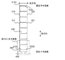
次に、図23、図24、図25及び図26を参照して実施例6のスロットライナー300について説明する。図23は実施例6のスロットライナー300の斜視図であり、図24は固定子コイル138が実装されたスロットライナー300の斜視図であり、図25はスロット420に実装されたスロットライナー300を軸方向から見た図であり、図26は図25の一部の拡大図である。実施例6において、前述した実施例との相違点を主に説明し、同じ構造及び機能の部材には同じ符号を付し、それらの説明は省略する。
次に、図23、図24、図25及び図26を参照して実施例6のスロットライナー300について説明する。図23は実施例6のスロットライナー300の斜視図であり、図24は固定子コイル138が実装されたスロットライナー300の斜視図であり、図25はスロット420に実装されたスロットライナー300を軸方向から見た図であり、図26は図25の一部の拡大図である。実施例6において、前述した実施例との相違点を主に説明し、同じ構造及び機能の部材には同じ符号を付し、それらの説明は省略する。
実施例6のスロットライナー300は、実施例1と同様に、複数のコイル挿入穴330を形成し、一つのコイル挿入穴330に1本の固定子コイル138が配置される。実施例6のスロットライナー300は、第1突出部312を有する第1絶縁部材310と、第2突出部322を有する第2絶縁部材320とで構成され、第1絶縁部材310と第2絶縁部材320とを組み合わせて偶数個(図では8個)のコイル挿入穴330が形成される。
図25及び図26に示すように、第1絶縁部材310の最内周の第1長突出部312Lは厚く、すなわち径方向の大きさが大きい太突出部340を構成している。この太突出部340は、最内周の長突出部312L、322Lで形成すればよいので、第1絶縁部材310と第2絶縁部材320のいずれに設けてもよく、第1絶縁部材310及び第2絶縁部材320の両方に設けてもよい。
以上に説明したように、実施例6のスロットライナー300では、スロット420内の外周側に寄って固定子コイル138が配置されるので、固定子コア132に流れる渦電流を低減でき、回転電機100の効率を向上できる。
<実施例7>
次に、図27、図28及び図29を参照して実施例7のスロットライナー300について説明する。図27は、第1絶縁部材310と第2絶縁部材320とが組み合わされたスロットライナー300の断面図であり、図28は固定子コイル138の挿入時のスロットライナー300の示す図であり、図29は固定子コイル138の挿入後のスロットライナー300の示す図である。実施例7において、前述した実施例1との相違点を主に説明し、同じ構造及び機能の部材には同じ符号を付し、それらの説明は省略する。
次に、図27、図28及び図29を参照して実施例7のスロットライナー300について説明する。図27は、第1絶縁部材310と第2絶縁部材320とが組み合わされたスロットライナー300の断面図であり、図28は固定子コイル138の挿入時のスロットライナー300の示す図であり、図29は固定子コイル138の挿入後のスロットライナー300の示す図である。実施例7において、前述した実施例1との相違点を主に説明し、同じ構造及び機能の部材には同じ符号を付し、それらの説明は省略する。
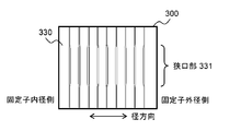
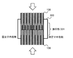
実施例7のスロットライナー300は、実施例1と同様に、複数のコイル挿入穴330を形成し、一つのコイル挿入穴330に1本の固定子コイル138が配置される。実施例7のスロットライナー300は、コイル挿入穴330の内部に狭口部331が設けられている。
狭口部331はスロットライナー300の内部に設ければよいが、スロット420の内部で2本のセグメントコイルが接続される構造の場合、当該接続位置を含む軸方向の所定の長さにおいて狭口部331を設けるとよい。
コイル挿入穴330は第1基部311、第1突出部312、第2基部321、第2突出部322が壁面となって形成されることから、これらの壁の1以上にコイル挿入穴330の方向に突出した凸部を樹脂成形によって設けて、狭口部331を形成するとよい。なお、狭口部331を形成する凸部は、相対する面の両方(例えば、第1基部311及び第2基部321の組、突出部312、322の組)に設けるとよいが、一つの面のみに設けてもよい。
このように、実施例7では、スロットライナー300の内部に狭口部331を設けることによって、固定子コイル138の位置を容易に定められ、ワニスを注入する前の固定子コイル138のズレを抑制できる。特に、後工程において固定子コイル138の溶接側で導線を曲げる際のコイルのズレを防止できる。また、スロット420の内部で接続される2本のセグメントコイルの接続部の動きを抑制し、導通不良を抑制できる。
以上に説明したように、本発明の実施例の固定子130は、絶縁部材(スロットライナー300)は、互いに組み合わされてコイル挿入用の矩形(コイル挿入穴330)を形成する第1絶縁部材310及び第2絶縁部材320によって構成され、第1絶縁部材310は、収容空間(スロット420)の内壁に沿って配置される板状の第1基部311と、径方向に沿って並んで配置され、第1基部311から第2絶縁部材320に向けて突出する複数の第1突出部312とを有し、第2絶縁部材320は、スロット420の内壁に沿って配置される板状の第2基部321と、径方向に沿って並んで配置され、第2基部321から第1絶縁部材310に向けて突出する複数の第2突出部322とを有し、第1突出部312と第2突出部322とは周方向に延在する面で接触するので、固定子コイル138間や固定子コイル138とスロット420の内壁との間で樹脂による絶縁体の隙間をなくすことができ、絶縁性を向上できる。また、スロット420内でスロットライナー300の変形を防止でき、固定子コイル138を固定子コア132へ容易に実装できる。
また、複数の第1突出部312は、第1長突出部312Lと、第1長突出部312Lより短い第1短突出部312Sとの少なくとも一方を含み、複数の第2突出部322は、第2長突出部322Lと、第2長突出部322Lより短い第2短突出部322Sとの少なくとも一方を含み、第1長突出部312Lと相対する位置には、第2長突出部322L又は第2短突出部322Sが配置され、第1短突出部312Sと相対する位置には、第2長突出部322Lが配置されるので、同じ形状の二つの部品(第1絶縁部材310、第2絶縁部材320)を組み合わせてスロットライナー300が構成でき、部品のコストを低減できる。
また、第1長突出部312Lと第2長突出部322Lとが相対する位置では、第1長突出部312Lと第2長突出部322Lとが周方向に延在する面で接触しており、固定子コイル138の間は第1長突出部312L及び第2長突出部322Lの2枚の絶縁体で離隔されるので、当該箇所ではコイル間の絶縁性を向上でき、異なる相のコイル間でも十分な絶縁性を確保できる。
また、第1突出部312は第1長突出部312Lであり、第2突出部322は第2短突出部322Sであり、第1長突出部312Lの長さは、第1絶縁部材310と第2絶縁部材320とが組み合わされて絶縁体が構成される際に、周方向に延在する面で第2短突出部322Sと接触可能な長さとしたので、絶縁部材310、320の反りを抑制でき、第1絶縁部材310及び第2絶縁部材320をスロット420内に配置した際に、コイル挿入穴330が狭くならず、固定子コイル138の挿入性の低下を抑制でき、作業性を向上できる。
また、第1絶縁部材310と第2絶縁部材320とは同じ形状であり、第1絶縁部材310と第2絶縁部材320とを対称に配置して組み合わせることによって、コイル挿入用の矩形(コイル挿入穴330)を有する絶縁部材(スロットライナー300)が構成されるので、同じ形状の二つの部品(第1絶縁部材310、第2絶縁部材320)を組み合わせてスロットライナー300が構成でき、部品のコストを低減できる。
また、Nを正の整数(例えば9個)として、第1基部311には、一端側(外周側)から第1長突出部312Lが2N-1個並べて配置され、他端側(内周側)から第1短突出部312Sが2N個並べて配置され、第2基部321には、他端側(内周側)から第2長突出部322Lが2N-1個並べて配置され、一端側(外周側)から第2短突出部322Sが2N個並べて配置され、第1基部311の一端側(外周側)から2N-1番目の第1長突出部312Lと第2基部321の他端側(内周側)から数えて2N-1番目の第2長突出部322Lとは、周方向に延在する面で接触するので、固定子コイル138の占積率を低下させずに、当該箇所では固定子コイル138の間の絶縁性を向上できる。
また、第1突出部312と第2突出部322とは同じ長さであり、第1突出部312の長さは、第1絶縁部材310と第2絶縁部材320とが絶縁部材(スロットライナー300)として組み合わされた状態で、周方向に延在する面で第2突出部322と接触可能な長さとしたので、2枚の絶縁体によって隣接する固定子コイル138の間の絶縁性を向上できる。また、固定子コイル138の幅(周方向の大きさ)が異なり、スロット420の幅が広くても、同じ絶縁部材を使用できる。
また、第1絶縁部材310と第2絶縁部材320とが絶縁部材(スロットライナー300)として組み合わされた状態で、第1基部311及び第2基部321の少なくとも一つの外側面に段差を設けて、ストッパー部313を構成し、ストッパー部313と固定子コア132の軸方向端面とが当接するので、スロットライナー300をスロット420に挿入した際に、スロットライナー300を固定子コア132に正確に位置決めできる。また、スロット420への固定子コイル138の挿入時にも、固定子コア132におけるスロットライナー300の軸方向の位置を維持し、スロットライナー300のズレを防止できる。
また、第1絶縁部材310の最内周側の第1突出部312と、第2絶縁部材320の最内周側の第2突出部322との少なくとも一つが、他の第1突出部312及び第2突出部322より、径方向が大きいので、スロット420内の外周側に寄って固定子コイル138が配置されるので、固定子コア132に流れる渦電流を低減でき、回転電機100の効率を向上できる。
また、第1基部311、第1突出部312、第2基部321及び第2突出部322の少なくとも一つに、前記コイル挿入用の矩形の内側方向に突出する凸部を設けて、狭口部331を構成したので、固定子コイル138の位置を容易に定められ、ワニスを注入する前の固定子コイル138のズレを抑制できる。特に、後工程において固定子コイル138の溶接側で導線を曲げる際のコイルのズレを防止できる。また、スロット420の内部で接続される2本のセグメントコイルの接続部の動きを抑制し、導通不良を抑制できる。
なお、以上の説明はあくまでも一例であり、発明を解釈する際、上記実施の形態の記載事項と特許請求の範囲の記載事項の対応関係に何ら限定も拘束もされない。例えば、上述した実施の形態では回転子に永久磁石を備えた回転電機を例に説明したが、本発明は、誘導モータ等の回転電機の固定子にも同様に適用することができる。また、車両駆動用回転電機以外にも適用できる。
なお、本発明は前述した実施例に限定されるものではなく、添付した特許請求の範囲の趣旨内における様々な変形例及び同等の構成が含まれる。例えば、前述した実施例は本発明を分かりやすく説明するために詳細に説明したものであり、必ずしも説明した全ての構成を備えるものに本発明は限定されない。また、ある実施例の構成の一部を他の実施例の構成に置き換えてもよい。また、ある実施例の構成に他の実施例の構成を加えてもよい。また、各実施例の構成の一部について、他の構成の追加・削除・置換をしてもよい。
10 ケース
12 ボルト
14A、14B 軸受け
28 セグメントコイル
100 回転電機
112 ハウジング
115 フランジ
118 回転軸
130 固定子
132 固定子コア
133 電磁鋼板
138 固定子コイル
140a コイルエンド
140b コイルエンド
150 回転子
152 回転子鉄心
154 永久磁石
156 磁気的空隙
300 スロットライナー
310 第1絶縁部材
311 第1基部
312 第1突出部
312L 第1長突出部
312S 第1短突出部
313 ストッパー部
320 第2絶縁部材
321 第2基部
322 第2突出部
322L 第2長突出部
322S 第2短突出部
330 コイル挿入穴
331 狭口部
340 太突出部
420 スロット
430 ティース
440 コアバック
Claims (11)
- 回転電機の固定子であって、
コイルと、
前記コイルと接する絶縁部材と、
前記コイル及び前記絶縁部材の収容空間を形成するコア部と、を備え、
前記絶縁部材は、互いに組み合わされてコイル挿入用の矩形を形成する第1絶縁部材及び第2絶縁部材によって構成され、
前記第1絶縁部材は、前記収容空間の内壁に沿って配置される板状の第1基部と、径方向に沿って並んで配置され、前記第1基部から前記第2絶縁部材に向けて突出する複数の第1突出部とを有し、
前記第2絶縁部材は、前記収容空間の内壁に沿って配置される板状の第2基部と、径方向に沿って並んで配置され、前記第2基部から前記第1絶縁部材に向けて突出する複数の第2突出部とを有し、
前記第1突出部と前記第2突出部とは周方向に延在する面で接触することを特徴とする回転電機の固定子。 - 請求項1に記載の回転電機の固定子であって、
前記複数の第1突出部は、第1長突出部と、前記第1長突出部より短い第1短突出部との少なくとも一方を含み、
前記複数の第2突出部は、第2長突出部と、前記第2長突出部より短い第2短突出部との少なくとも一方を含み、
第1長突出部と相対する位置には、前記第2長突出部又は前記第2短突出部が配置され、
第1短突出部と相対する位置には、前記第2長突出部が配置されることを特徴とする回転電機の固定子。 - 請求項2に記載の回転電機の固定子であって、
前記第1長突出部と前記第2長突出部とが相対する位置では、前記第1長突出部と前記第2長突出部とが周方向に延在する面で接触しており、前記コイルの間は前記第1長突出部及び前記第2長突出部の2枚の絶縁体で離隔されることを特徴とする回転電機の固定子。 - 請求項2に記載の回転電機の固定子であって、
前記第1突出部は前記第1長突出部であり、
前記第2突出部は前記第2短突出部であり、
前記第1長突出部の長さは、前記第1絶縁部材と前記第2絶縁部材とが絶縁部材として組み合わされた状態で、周方向に延在する面で前記第2短突出部と接触可能な長さであることを特徴とする回転電機の固定子。 - 請求項2に記載の回転電機の固定子であって、
前記第1絶縁部材と前記第2絶縁部材とは同じ形状であり、
前記第1絶縁部材と前記第2絶縁部材とを対称に配置して組み合わせることによって、前記コイル挿入用の矩形を有する絶縁部材が構成されることを特徴とする回転電機の固定子。 - 請求項5に記載の回転電機の固定子であって、
Nを正の整数として、
前記第1基部には、一端側から前記第1長突出部が2N-1個並べて配置され、他端側から前記第1短突出部が2N個並べて配置され、
前記第2基部には、前記他端側から前記第2長突出部が2N-1個並べて配置され、前記一端側から前記第2短突出部が2N個並べて配置され、
前記第1基部の前記一端側から2N-1番目の前記第1長突出部と前記第2基部の前記他端側から数えて2N-1番目の前記第2長突出部とは、周方向に延在する面で接触することを特徴とする回転電機の固定子。 - 請求項1に記載の回転電機の固定子であって、
前記第1突出部と前記第2突出部とは同じ長さであり、
前記第1突出部の長さは、前記第1絶縁部材と前記第2絶縁部材とが絶縁部材として組み合わされた状態で、周方向に延在する面で前記第2突出部と接触可能な長さであることを特徴とする回転電機の固定子。 - 請求項1に記載の回転電機の固定子であって、
前記第1絶縁部材と前記第2絶縁部材とが絶縁部材として組み合わされた状態で、前記第1基部及び前記第2基部の少なくとも一つの外側面に段差を設け、
前記段差と前記コア部の軸方向端面とが当接することを特徴とする回転電機の固定子。 - 請求項1に記載の回転電機の固定子であって、
前記第1絶縁部材の最内周側の第1突出部と、前記第2絶縁部材の最内周側の第2突出部との少なくとも一つが、他の前記第1突出部及び前記第2突出部より、径方向に大きいことを特徴とする回転電機の固定子。 - 請求項1に記載の回転電機の固定子であって、
前記第1基部、前記第1突出部、前記第2基部及び前記第2突出部の少なくとも一つに、前記コイル挿入用の矩形の内側方向に突出する凸部を設けたことを特徴とする回転電機の固定子。 - 回転電機の固定子に実装される絶縁部材であって、
前記固定子は、コイル及び前記絶縁部材の収容空間を形成するコア部を有し、
前記絶縁部材は、互いに組み合わされてコイル挿入用の矩形を形成する第1絶縁部材及び第2絶縁部材によって構成され、
前記第1絶縁部材は、前記収容空間の内壁に沿って配置される板状の第1基部と、径方向に沿って並んで配置され、前記第1基部から前記第2絶縁部材に向けて突出する複数の第1突出部とを有し、
前記第2絶縁部材は、前記収容空間の内壁に沿って配置される板状の第2基部と、径方向に沿って並んで配置され、前記第2基部から前記第1絶縁部材に向けて突出する複数の第2突出部とを有し、
前記第1突出部と前記第2突出部とは周方向に延在する面で接触することを特徴とする絶縁部材。
Applications Claiming Priority (2)
| Application Number | Priority Date | Filing Date | Title |
|---|---|---|---|
| JP2019-020787 | 2019-02-07 | ||
| JP2019020787A JP2022053555A (ja) | 2019-02-07 | 2019-02-07 | 回転電機の固定子及び絶縁部材 |
Publications (1)
| Publication Number | Publication Date |
|---|---|
| WO2020162089A1 true WO2020162089A1 (ja) | 2020-08-13 |
Family
ID=71947202
Family Applications (1)
| Application Number | Title | Priority Date | Filing Date |
|---|---|---|---|
| PCT/JP2020/000232 Ceased WO2020162089A1 (ja) | 2019-02-07 | 2020-01-08 | 回転電機の固定子及び絶縁部材 |
Country Status (2)
| Country | Link |
|---|---|
| JP (1) | JP2022053555A (ja) |
| WO (1) | WO2020162089A1 (ja) |
Citations (2)
| Publication number | Priority date | Publication date | Assignee | Title |
|---|---|---|---|---|
| JP2003070201A (ja) * | 2001-08-23 | 2003-03-07 | Toyota Motor Corp | 回転電機のステータおよびその製造方法 |
| JP2007259649A (ja) * | 2006-03-24 | 2007-10-04 | Denso Corp | 絶縁部材及びその組付け方法 |
-
2019
- 2019-02-07 JP JP2019020787A patent/JP2022053555A/ja active Pending
-
2020
- 2020-01-08 WO PCT/JP2020/000232 patent/WO2020162089A1/ja not_active Ceased
Patent Citations (2)
| Publication number | Priority date | Publication date | Assignee | Title |
|---|---|---|---|---|
| JP2003070201A (ja) * | 2001-08-23 | 2003-03-07 | Toyota Motor Corp | 回転電機のステータおよびその製造方法 |
| JP2007259649A (ja) * | 2006-03-24 | 2007-10-04 | Denso Corp | 絶縁部材及びその組付け方法 |
Also Published As
| Publication number | Publication date |
|---|---|
| JP2022053555A (ja) | 2022-04-06 |
Similar Documents
| Publication | Publication Date | Title |
|---|---|---|
| EP2639933B1 (en) | Dynamo-electric machine | |
| JP6711901B2 (ja) | 電動機および空気調和機 | |
| JP5314908B2 (ja) | 回転電機の固定子および回転電機 | |
| US20190372408A1 (en) | Rotating electric machine | |
| JP6720306B2 (ja) | 回転電機の固定子 | |
| CN105723596B (zh) | 磁感应式电动机及其制造方法 | |
| CN108370178A (zh) | 轴向间隙型旋转电机及其制造方法 | |
| CN102132472A (zh) | 电机 | |
| CN112136264A (zh) | 旋转机以及绝缘体 | |
| JP6545387B2 (ja) | コンシクエントポール型の回転子、電動機および空気調和機 | |
| KR102492064B1 (ko) | 계자 권선형 모터용 로터 | |
| WO2018037455A1 (ja) | コンシクエントポール型の回転子、電動機および空気調和機 | |
| JP4535147B2 (ja) | 回転電機の固定子及び回転電機 | |
| JP2013207946A (ja) | 回転電機 | |
| JP7166207B2 (ja) | 回転電機およびその製造方法 | |
| US12308718B2 (en) | Molded coil, stator, and rotary electric machine | |
| CN112470369B (zh) | 旋转电机的定子 | |
| US20250192636A1 (en) | A bobbin | |
| KR20230073840A (ko) | 모터 | |
| JP7850892B2 (ja) | 回転子及び電動機 | |
| JP6429400B2 (ja) | ステータコア、ステータ及び回転電機 | |
| JP2017103986A (ja) | 電動機 | |
| JP7150171B2 (ja) | 回転電機の固定子、端子台及び回転電機 | |
| JP2022053555A (ja) | 回転電機の固定子及び絶縁部材 | |
| JP7800212B2 (ja) | 電機子及び回転電機 |
Legal Events
| Date | Code | Title | Description |
|---|---|---|---|
| 121 | Ep: the epo has been informed by wipo that ep was designated in this application |
Ref document number: 20752849 Country of ref document: EP Kind code of ref document: A1 |
|
| NENP | Non-entry into the national phase |
Ref country code: DE |
|
| 122 | Ep: pct application non-entry in european phase |
Ref document number: 20752849 Country of ref document: EP Kind code of ref document: A1 |
|
| NENP | Non-entry into the national phase |
Ref country code: JP |