WO2020162026A1 - 光配向用露光装置及び光配向用露光方法 - Google Patents
光配向用露光装置及び光配向用露光方法 Download PDFInfo
- Publication number
- WO2020162026A1 WO2020162026A1 PCT/JP2019/047893 JP2019047893W WO2020162026A1 WO 2020162026 A1 WO2020162026 A1 WO 2020162026A1 JP 2019047893 W JP2019047893 W JP 2019047893W WO 2020162026 A1 WO2020162026 A1 WO 2020162026A1
- Authority
- WO
- WIPO (PCT)
- Prior art keywords
- light
- alignment
- photo
- optical filter
- exposure
- Prior art date
- Legal status (The legal status is an assumption and is not a legal conclusion. Google has not performed a legal analysis and makes no representation as to the accuracy of the status listed.)
- Ceased
Links
Images


Classifications
-
- G—PHYSICS
- G02—OPTICS
- G02B—OPTICAL ELEMENTS, SYSTEMS OR APPARATUS
- G02B5/00—Optical elements other than lenses
- G02B5/20—Filters
- G02B5/26—Reflecting filters
-
- G—PHYSICS
- G02—OPTICS
- G02B—OPTICAL ELEMENTS, SYSTEMS OR APPARATUS
- G02B5/00—Optical elements other than lenses
- G02B5/30—Polarising elements
-
- G—PHYSICS
- G02—OPTICS
- G02F—OPTICAL DEVICES OR ARRANGEMENTS FOR THE CONTROL OF LIGHT BY MODIFICATION OF THE OPTICAL PROPERTIES OF THE MEDIA OF THE ELEMENTS INVOLVED THEREIN; NON-LINEAR OPTICS; FREQUENCY-CHANGING OF LIGHT; OPTICAL LOGIC ELEMENTS; OPTICAL ANALOGUE/DIGITAL CONVERTERS
- G02F1/00—Devices or arrangements for the control of the intensity, colour, phase, polarisation or direction of light arriving from an independent light source, e.g. switching, gating or modulating; Non-linear optics
- G02F1/01—Devices or arrangements for the control of the intensity, colour, phase, polarisation or direction of light arriving from an independent light source, e.g. switching, gating or modulating; Non-linear optics for the control of the intensity, phase, polarisation or colour
- G02F1/13—Devices or arrangements for the control of the intensity, colour, phase, polarisation or direction of light arriving from an independent light source, e.g. switching, gating or modulating; Non-linear optics for the control of the intensity, phase, polarisation or colour based on liquid crystals, e.g. single liquid crystal display cells
- G02F1/133—Constructional arrangements; Operation of liquid crystal cells; Circuit arrangements
- G02F1/1333—Constructional arrangements; Manufacturing methods
- G02F1/1337—Surface-induced orientation of the liquid crystal molecules, e.g. by alignment layers
Definitions
- the present invention relates to an exposure device and an exposure method used to perform optical alignment of a liquid crystal alignment film.
- the pretilt angle is an angle formed by the long axis of the liquid crystal molecules along the liquid crystal alignment axis and the alignment surface, and is a factor for adjusting the alignment process that greatly affects the display characteristics of the LCD.
- the "diagonal exposure method” in which light is obliquely irradiated to the surface of the photo-alignment film at an arbitrary angle from the normal direction.
- an exposure apparatus for performing the “oblique exposure method” there is known an exposure apparatus including an irradiation unit that sets an irradiation angle with respect to a photo-alignment film via a plurality of reflection plates by using a light source having high directivity. (See Patent Document 1 below).
- the above-described conventional exposure apparatus that performs the “oblique exposure method” has a problem that the light source is limited to a relatively expensive and highly directional light source, and a plurality of reflectors and a space for securing the optical path length are required.
- the problem was that the irradiation part became large.
- the present invention aims to address such a problem. That is, it is possible to use an inexpensive scattering light source (volume light source) in a photo-alignment exposure apparatus that performs an oblique exposure method that allows a stable pretilt angle to appear, and to perform uniform light irradiation even in a compact form. That is the issue.
- volume light source volume light source
- the present invention has the following configurations.
- An exposure apparatus for optical alignment for performing polarized light scanning exposure on a surface to be illuminated that becomes a photo-alignment film, a light source that emits scattered light toward the surface to be illuminated, and light emitted from the light source,
- An optical filter that selectively emits the photosensitive wavelength of the photo-alignment film, and a light limiting member that asymmetrically limits the light passing through the optical filter in the front-back direction of the scanning direction, and the optical filter is in the scanning direction.
- optical alignment characterized by having a wavelength transmission characteristic in which the transmittance of light of the above-mentioned photosensitive wavelength becomes a peak in oblique exposure in which the irradiation angle along the line is a set angle or more with respect to the normal direction of the surface to be irradiated. Exposure equipment.
- the exposure method for photo-alignment which has wavelength transmission characteristics in which the transmittance of the light of the photosensitive wavelength reaches a peak, and asymmetrically restricts the light passing through the optical filter in the front-back direction of the scanning direction.
- the X direction in the drawing indicates the scanning direction
- the Y direction in the drawing indicates the direction intersecting with the scanning direction in the horizontal plane
- the Z direction in the drawing indicates the vertical direction (the normal direction of the irradiated surface).
- the photo-alignment exposure apparatus 1 performs polarization scanning exposure on a surface to be irradiated 10S that is a photo-alignment film, and in the illustrated example, a substrate mounted on a stage 20.
- the exposed surface 10S of the photosensitive resin film formed on the surface of 10 is subjected to scanning exposure for irradiating polarized light having a photosensitive wavelength.
- scanning exposure light irradiation is performed on the surface to be irradiated 10S while moving the optical alignment exposure device 1 with respect to the stage 20 in the X direction shown in the drawing, or the stage 20 is provided with respect to the optical alignment exposure device 1 in the X direction shown in the drawing.
- Light irradiation is performed on the surface to be irradiated 10S while moving to 10. Further, scanning exposure may be performed by moving the optical alignment exposure device 1 and the stage 20 in opposite directions along the X direction in the drawing.
- the exposure apparatus 1 for photo-alignment includes a light source 2 that emits scattered light toward the surface (irradiated surface 10S) of a photosensitive resin film on the substrate 10, and a photo-alignment film of the light emitted from the light source 2.
- An optical filter 3 that selectively emits a wavelength (a reaction wavelength of the photosensitive resin film), and a light limiting member 4 that asymmetrically limits the light passing through the optical filter 3 in the front-back direction of the scanning direction (X direction in the drawing),
- the polarizer 5 is provided to convert the light to be irradiated onto the surface to be irradiated 10S into polarized light.
- the light source 2 includes a long lamp 2A along the scanning direction (X direction in the drawing), and a reflector 2B that directs scattered light emitted from the lamp 2A toward the irradiation surface 10S.
- the reflector 2B has a parabolic or elliptic arc-shaped reflection surface as shown in FIG. 1 in a cross section orthogonal to the scanning direction (X direction in the drawing).
- the irradiation angle is not limited to the light on the surface perpendicular to 10S and parallel to the scanning direction. Therefore, the light on this surface enters the optical filter 3 at various irradiation angles.
- light along the scanning direction refers to light on a surface that is perpendicular to the surface to be illuminated 10S and that is parallel to the scanning direction
- the irradiation angle along the scanning direction is as shown in FIG.
- the irradiation angle of light on a surface that is perpendicular to the surface to be irradiated 10S and that is parallel to the scanning direction is indicated.
- the irradiation angle refers to the irradiation angle of light with respect to the normal direction of the surface to be irradiated 10S.
- the optical filter 3 transmits the wavelength of the irradiation light along the scanning direction so that the wavelength of the light that obliquely exposes the surface to be irradiated 10S becomes the photosensitive wavelength (the reaction wavelength of the photosensitive resin film serving as the photo-alignment film).
- the characteristic is set.
- Such an optical filter 3 can be formed by a dielectric multilayer filter.
- the dielectric multilayer filter has a difference in the optical path length when passing through each layer between the light passing vertically through each film layer and the light passing diagonally, so the selected wavelength changes depending on the passing angle of the transmitted light. Will be done. Utilizing the characteristics of this dielectric multilayer film filter, as shown in FIG.
- the selected wavelength ⁇ v of the light Lv emitted in the direction normal to the surface 10S to be illuminated is ⁇ v> ⁇ s.
- FIG. 3 shows the wavelength transmission characteristics of the optical filter 3.
- the optical filter 3 has a wavelength transmission where the transmittance of the photosensitive wavelength reaches a peak in oblique exposure in which the irradiation angle along the scanning direction is a set angle ⁇ s or more with respect to the normal direction of the surface to be irradiated 10S. It has characteristics. In the illustrated example, when the set angle ⁇ s is 55° or more, the transmittance of the photosensitive wavelength has a peak.
- the characteristics of the optical filter 3 shown in FIG. 3 are preferably such that the transmittance rises more steeply near the set angle as the irradiation angle increases.
- the light restricting member 4 in the exposure apparatus 1 for optical alignment realizes oblique exposure of light having a photosensitive wavelength by restricting the light passing through the optical filter 3 asymmetrically in the front-back direction of the scanning direction.
- the scattered light emitted from the lamp 2A is not restricted in the direction of the light along the scanning direction. Therefore, when the light restricting member 4 does not exist, the irradiation light having the set angle ⁇ s or more is on both front and rear sides in the scanning direction. And symmetrically exist, and their combined specific gravity irradiation angles are ⁇ 0°. Therefore, substantially oblique exposure cannot be realized without the light limiting member 4.
- the light limiting member 4 may be any one that can realize oblique exposure by breaking this symmetry, and as shown in FIG. 2, an angle ⁇ s that is symmetric with respect to the light Ls having the irradiation angle of the set angle ⁇ s. It is sufficient that the light Ls′ is blocked.
- FIG. 4 shows a specific configuration example of the light limiting member 4.
- the light restricting member 4 shields one of the oblique exposures that are symmetrical in the front-rear direction of the scanning direction, and when performing the oblique exposure at the set angle ⁇ s, the light along the scanning direction is set at the set angle ⁇ s.
- the openings 4A that allow the obliquely irradiated light Ls to pass therethrough and the light shielding portions 4B that are symmetrical to the openings 4A and shield the light Ls' having an irradiation angle of - ⁇ s are alternately provided.
- the light restricting member 4 does not need to regulate the angle of light passing therethrough as long as it can impart asymmetry to the irradiation angle of light along the scanning direction. Need not be processed.
- the polarizer 5 in the exposure apparatus 1 for photo-alignment is for making the light passing through the optical filter 3 and the light restricting member 4 into polarized light and irradiating the irradiated surface 10S with a wire grid having no polarization dependence on the polarization characteristics. It is preferable to use a polarizer.
- the polarizer 5 can also serve as the light limiting member 4, and the individual light limiting member 4 can be omitted. ..
- FIG. 5 shows an example of the configuration of the photo-alignment exposure device 1 in which the polarizer 5 also serves as a light limiting member.
- the polarizer 5 is provided with two wire grid polarizers 5A and 5B for one lamp 2A, each wire grid polarizer 5A and 5B is held by a holder 5H, and the holder 5H is mounted on a support frame 5F. It is supported.
- the set angle ⁇ s in the optical filter 3 is When the relationship of ⁇ a ⁇ s is satisfied, by providing the light shield 6 that closes the opening of the wire grid polarizer 5B (or 5A) on one side, it is possible to perform oblique exposure with the photosensitive wavelength even if the light limiting member is omitted. Become. This is because the light shield 6 imparts asymmetry to the irradiation angle ⁇ s of light along the scanning direction.
- the optical filter 3 has a method in which the irradiation angle along the scanning direction is the irradiated surface 10S.
- It has a wavelength transmission characteristic that the transmittance of light of a photosensitive wavelength has a peak when oblique exposure is performed at a set angle or more with respect to the line direction, and light passing through the optical filter 3 is asymmetrically limited in the front-back direction of the scanning direction. ..
- oblique exposure that allows the pretilt angle to appear stably can be performed using an inexpensive scattering light source (volume light source), and even if the photo-alignment exposure apparatus 1 is compact, it is uniform. Various light irradiation becomes possible. Furthermore, since an optical member (louver or the like) for precisely limiting the irradiation direction of light obliquely is not necessary, it is possible to realize oblique exposure that effectively makes the pretilt angle appear with relatively inexpensive equipment.
- 1 exposure device for optical alignment
- 2 light source
- 2A lamp
- 2B reflector
- 3 optical filter
- 4 light limiting member
- 5 polarizer
- 5A, 5B Wire grid polarizer
- 5H Holder
- 5F Support frame
- 6 Light shield
- 10 Substrate
- 10S Irradiated surface
- 20 Stage
Landscapes
- Physics & Mathematics (AREA)
- General Physics & Mathematics (AREA)
- Optics & Photonics (AREA)
- Nonlinear Science (AREA)
- Spectroscopy & Molecular Physics (AREA)
- Mathematical Physics (AREA)
- Chemical & Material Sciences (AREA)
- Crystallography & Structural Chemistry (AREA)
- Liquid Crystal (AREA)
- Exposure And Positioning Against Photoresist Photosensitive Materials (AREA)
- Optical Filters (AREA)
- Polarising Elements (AREA)
Abstract
本発明は、プレチルト角を安定して出現させる斜め露光法を行う光配向露光装置において、安価な散乱光源(体積光源)を用いることができ、コンパクトな形態であっても均一な光照射を可能にすることを課題とする。 本発明の光配向用露光装置(1)は、光配向膜となる被照射面に対して偏光走査露光を行うものであり、被照射面に向けて散乱光を出射する光源(2)と、光源(2)から出射された光のうち、光配向膜の感光波長を選択的に出射する光学フィルタ(3)と、光学フィルタ(3)を通過した光を走査方向(X)の前後方向で非対称に制限する光制限部材(4)とを備え、光学フィルタ(3)は、走査方向(X)に沿った照射角度が被照射面の法線方向に対して設定角度(θs)以上の斜め露光で、感光波長の光の透過率がピークになる波長透過特性を有する。
Description
本発明は、液晶配向膜の光配向を行うために用いられる露光装置及び露光方法に関するものである。
液晶ディスプレイ(LCD)の使用用途の多様化の中で、VR(仮想現実)やAR(拡張現実)などの用途を目的とした高精細化、応答速度の高速化、透過率の向上を進める上で、液晶配向処理におけるプレチルト角の安定化とコントラストの向上が重要な課題になっている。プレチルト角とは、液晶配向軸に沿った液晶分子の長軸と配向面とのなす角度であり、LCDの表示特性に大きく影響する配向処理の調整因子である。
光配向法において安定したプレチルト角を出現させるには、光配向膜表面に対して法線方向から任意の角度で斜めに光照射を行う「斜め露光法」が有効であるとされている。従来、「斜め露光法」を行う露光装置としては、指向性の高い光源を用いて、複数の反射板を介して光配向膜に対する照射角度を設定する照射部を備えたものが知られている(下記特許文献1参照)。
「斜め露光法」を行う前述した従来の露光装置は、光源が比較的高価な指向性の高いものに限定される問題があると共に、複数の反射板と光路長確保のための空間を要することで、照射部が大型になることが問題になっていた。
本発明は、このような問題に対処することを課題としている。すなわち、プレチルト角を安定して出現させる斜め露光法を行う光配向露光装置において、安価な散乱光源(体積光源)を用いることができること、コンパクトな形態であっても均一な光照射が可能であること、などを課題としている。
このような課題を解決するために、本発明は、以下の構成を具備するものである。
光配向膜となる被照射面に対して偏光走査露光を行う光配向用露光装置であって、前記被照射面に向けて散乱光を出射する光源と、前記光源から出射された光のうち、前記光配向膜の感光波長を選択的に出射する光学フィルタと、前記光学フィルタを通過した光を走査方向の前後方向で非対称に制限する光制限部材とを備え、前記光学フィルタは、走査方向に沿った照射角度が前記被照射面の法線方向に対して設定角度以上となる斜め露光で、前記感光波長の光の透過率がピークになる波長透過特性を有することを特徴とする光配向用露光装置。
光配向膜となる被照射面に対して偏光走査露光を行う光配向用露光装置であって、前記被照射面に向けて散乱光を出射する光源と、前記光源から出射された光のうち、前記光配向膜の感光波長を選択的に出射する光学フィルタと、前記光学フィルタを通過した光を走査方向の前後方向で非対称に制限する光制限部材とを備え、前記光学フィルタは、走査方向に沿った照射角度が前記被照射面の法線方向に対して設定角度以上となる斜め露光で、前記感光波長の光の透過率がピークになる波長透過特性を有することを特徴とする光配向用露光装置。
光配向膜となる被照射面に対して偏光走査露光を行う光配向用露光方法であって、光源からの散乱光を光学フィルタを通過させて前記被照射面に出射し、前記光学フィルタは、前記光源から出射された光のうち、前記光配向膜の感光波長を選択的に出射し、走査方向に沿った照射角度が前記被照射面の法線方向に対して設定角度以上となる斜め露光で、前記感光波長の光の透過率がピークになる波長透過特性を有し、前記光学フィルタを通過した光を走査方向の前後方向で非対称に制限することを特徴とする光配向用露光方法。
以下、図面を参照して本発明の実施形態を説明する。以下の説明で異なる図における同一符号は同一機能の部位を示しており、各図における重複説明は適宜省略する。図示のX方向が走査方向を示し、図示のY方向は、水平面内での走査方向と交差する方向を示し、図示のZ方向は、鉛直方向(被照射面の法線方向)を示している。
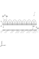
図1に示すように、光配向用露光装置1は、光配向膜となる被照射面10Sに対して偏光走査露光を行うものであり、図示の例では、ステージ20上に載置された基板10の表面に形成された感光性樹脂膜の被照射面10Sに、感光波長の偏光光を照射する走査露光を行っている。走査露光は、ステージ20に対して光配向用露光装置1を図示X方向に移動させながら被照射面10Sに対する光照射を行うか、或いは光配向用露光装置1に対してステージ20を図示X方向に移動させながら被照射面10Sに対する光照射を行う。また、光配向用露光装置1とステージ20とを図示X方向に沿って互いに逆向きに移動させることで走査露光を行ってもよい。
光配向用露光装置1は、基板10上の感光樹脂膜の表面(被照射面10S)に向けて散乱光を出射する光源2と、光源2から出射された光のうち、光配向膜の感光波長(感光性樹脂膜の反応波長)を選択的に出射する光学フィルタ3と、光学フィルタ3を通過した光を走査方向(図示X方向)の前後方向で非対称に制限する光制限部材4と、被照射面10Sに照射する光を偏光光にする偏光子5を備えている。
光源2は、図2に示すように、走査方向(図示X方向)に沿って長尺なランプ2Aと、ランプ2Aから出射される散乱光を被照射面10Sに向けるリフレクタ2Bを備えている。リフレクタ2Bは、走査方向(図示X方向)に直交する断面では、図1に示すように放物線又は楕円弧状の反射面を有しているが、ランプ2Aから出射される光のうち、被照射面10Sに垂直な面であり且つ走査方向と平行な面上の光には照射角度の制限を加えていない。このため、この面上の光は様々な照射角度で光学フィルタ3に入射することになる。
なお、以下の説明で、走査方向に沿った光とは、被照射面10Sに垂直な面であり走査方向と平行な面上の光を指し、走査方向に沿った照射角度とは、図2に示すように、被照射面10Sに垂直な面であり走査方向と平行な面上の光の照射角度を指している。また、照射角度とは、被照射面10Sの法線方向に対する光の照射角度を指している。
光学フィルタ3は、走査方向に沿った照射光のうち、被照射面10Sを斜め露光する光の波長が感光波長(光配向膜となる感光性樹脂膜の反応波長)になるように、波長透過特性が設定されている。このような光学フィルタ3は、誘電体多層膜フィルタによって形成することができる。誘電体多層膜フィルタは、各膜の層を垂直に通過する光と斜めに通過する光とでは各層を通過する際の光路長に差が生じるので、透過する光の通過角度で選択波長が変化することになる。この誘電体多層膜フィルタの特性を利用すると、図2に示すように、光学フィルタ3を通過する光のうち、被照射面10Sの法線方向に向けて照射される光Lvの選択波長λvと、被照射面10Sの法線方向に対して設定角度θsで斜め照射される光Lsの選択波長λsとの関係は、λv>λsになる。
図3は、光学フィルタ3の波長透過特性を示している。ここでは、光配向膜の感光波長に着目して、被照射面10Sの法線方向に対する照射角度と透過率との関係を示している。図示のように、光学フィルタ3は、走査方向に沿った照射角度が被照射面10Sの法線方向に対して設定角度θs以上となる斜め露光で、感光波長の透過率がピークになる波長透過特性を有している。図示の例では、設定角度θsが55°以上で、感光波長の透過率がピークになっている。光配向膜に安定したプレチルト角を付与するためには、図3に示す光学フィルタ3の特性は、照射角度の上昇に対して透過率が設定角度付近でより急峻に立ち上がることが好ましい。
光配向用露光装置1における光制限部材4は、光学フィルタ3を通過した光を走査方向の前後方向で非対称に制限することで、感光波長の光の斜め露光を実現する。ランプ2Aから出射される散乱光は、走査方向に沿った光の方向が制限されていないので、光制限部材4が存在しない場合には、設定角度θs以上の照射光は、走査方向の前後両側で対称的に存在し、これらの合成比重照射角は±0°になる。よって、光制限部材4無しでは、実質的な斜め露光が実現できなくなる。光制限部材4は、この対称性を崩すことで、斜め露光を実現できるものであればよく、図2に示すように、設定角度θsの照射角の光Lsに対して対称となる角度-θsの光Ls’を遮光するものなどであればよい。
図4は、光制限部材4の具体的な構成例を示している。この光制限部材4は、走査方向の前後方向で対称となる斜め露光の一方を遮光するものであり、設定角度θsで斜め露光を行う際には、走査方向に沿った光で設定角度θsで斜めに照射される光Lsを通過させる開口部4Aと、それとは対称の-θsの照射角度の光Ls’を遮光する遮光部4Bを交互に備えている。光制限部材4は、それ自体で通過する光の角度を規制する必要は無く、走査方向に沿った光の照射角度に非対称性が付与できれば良いので、高い加工精度で開口部4Aや遮光部4Bを加工する必要が無い。
光配向用露光装置1における偏光子5は、光学フィルタ3と光制限部材4を通過した光を偏光光にして被照射面10Sに照射するものであり、偏光特性に角度依存性がないワイヤーグリッド偏光子を用いることが好ましい。また、偏光子5の配置によって、走査方向の前後方向の光に非対称性が付与できる場合には、偏光子5に光制限部材4を兼用させ、個別の光制限部材4を省略することができる。
図5は、偏光子5によって光制限部材を兼用させた光配向用露光装置1の構成例を示している。ここでは、偏光子5が一つのランプ2Aに付き2つのワイヤーグリッド偏光子5A,5Bを備えており、各ワイヤーグリッド偏光子5A,5Bがホルダー5Hで保持され、ホルダー5Hは、支持枠5Fに支持されている。
このような構成において、ランプ2Aから照射される光が2つのワイヤーグリッド偏光子5A,5Bの境界部分のホルダー5Hに制限される照射上限角をθaとすると、光学フィルタ3における設定角度θsが、θa<θsの関係にあるときに、片側のワイヤーグリッド偏光子5B(又は5A)の開口を塞ぐ遮光体6を設けることで、光制限部材を省略しても、感光波長による斜め露光が可能になる。これは、遮光体6によって、走査方向に沿った光の照射角度θsに非対称性が付与されることになるからである。
このような光配向用露光装置1を用いた露光方法では、光配向膜となる被照射面に対して偏光走査露光を行うに際して、光源2からの散乱光を被照射面10Sに出射し、光学フィルタ3を通過することで、光源2から出射された光のうち、光配向膜の感光波長を選択的に出射し、光学フィルタ3は、走査方向に沿った照射角度が被照射面10Sの法線方向に対して設定角度以上となる斜め露光で、感光波長の光の透過率がピークになる波長透過特性を有し、光学フィルタ3を通過した光を走査方向の前後方向で非対称に制限する。
これによって、プレチルト角を安定して出現させることができる斜め露光を安価な散乱光源(体積光源)を用いて行うことができ、また、光配向用露光装置1がコンパクトな形態であっても均一な光照射が可能になる。更には、光の照射方向を精度良く斜めに制限する光学部材(ルーバーなど)が不要になるので、比較的安価な設備で、プレチルト角を効果的に出現させる斜め露光を実現することができる。
以上、本発明の実施の形態について図面を参照して詳述してきたが、具体的な構成はこれらの実施の形態に限られるものではなく、本発明の要旨を逸脱しない範囲の設計の変更等があっても本発明に含まれる。また、上述の各実施の形態は、その目的及び構成等に特に矛盾や問題がない限り、互いの技術を流用して組み合わせることが可能である。
1:光配向用露光装置,
2:光源,2A:ランプ,2B:リフレクタ,
3:光学フィルタ,4:光制限部材,5:偏光子,
5A,5B:ワイヤーグリッド偏光子,5H:ホルダー,5F:支持枠,
6:遮光体,10:基板,10S:被照射面,20:ステージ
2:光源,2A:ランプ,2B:リフレクタ,
3:光学フィルタ,4:光制限部材,5:偏光子,
5A,5B:ワイヤーグリッド偏光子,5H:ホルダー,5F:支持枠,
6:遮光体,10:基板,10S:被照射面,20:ステージ
Claims (10)
- 光配向膜となる被照射面に対して偏光走査露光を行う光配向用露光装置であって、
前記被照射面に向けて散乱光を出射する光源と、
前記光源から出射された光のうち、前記光配向膜の感光波長を選択的に出射する光学フィルタと、
前記光学フィルタを通過した光を走査方向の前後方向で非対称に制限する光制限部材とを備え、
前記光学フィルタは、走査方向に沿った照射角度が前記被照射面の法線方向に対して設定角度以上となる斜め露光で、前記感光波長の光の透過率がピークになる波長透過特性を有することを特徴とする光配向用露光装置。 - 前記光源は、走査方向に沿って長尺なランプを走査方向に交差する方向に複数並列していることを特徴とする請求項1記載の光配向用露光装置。
- 前記光制限部材は、走査方向の前後方向で対称となる前記斜め露光の一方を遮光することを特徴とする請求項1又は2に記載の光配向用露光装置。
- 前記光学フィルタは、誘電体多層膜フィルタであることを特徴とする請求項1~3のいずれか1項記載の光配向用露光装置。
- 前記光学フィルタを通過した光が通過する偏光子を備え、
前記偏光子は、ワイヤーグリッド偏光子であることを特徴とする請求項1~4のいずれか1項記載の光配向用露光装置。 - 光配向膜となる被照射面に対して偏光走査露光を行う光配向用露光方法であって、
光源からの散乱光を光学フィルタを通過させて前記被照射面に出射し、
前記光学フィルタは、前記光源から出射された光のうち、前記光配向膜の感光波長を選択的に出射し、走査方向に沿った照射角度が前記被照射面の法線方向に対して設定角度以上となる斜め露光で、前記感光波長の光の透過率がピークになる波長透過特性を有し、
前記光学フィルタを通過した光を走査方向の前後方向で非対称に制限することを特徴とする光配向用露光方法。 - 前記光源として、走査方向に沿って長尺なランプを走査方向に交差する方向に複数並列したものを用いることを特徴とする請求項6記載の光配向用露光方法。
- 前記光学フィルタを通過した光は、走査方向の前後方向で対称となる前記斜め露光の一方が遮光されることで非対称に制限されることを特徴とする請求項6又は7に記載の光配向用露光方法。
- 前記光学フィルタとして、誘電体多層膜フィルタを用いることを特徴とする請求項6~8のいずれか1項記載の光配向用露光方法。
- 前記光学フィルタを通過した光は、ワイヤーグリッド偏光子によって偏光光とされることを特徴とする請求項6~9のいずれか1項記載の光配向用露光方法。
Priority Applications (1)
| Application Number | Priority Date | Filing Date | Title |
|---|---|---|---|
| CN201980090616.3A CN113366380A (zh) | 2019-02-07 | 2019-12-06 | 光取向用曝光装置及光取向用曝光方法 |
Applications Claiming Priority (2)
| Application Number | Priority Date | Filing Date | Title |
|---|---|---|---|
| JP2019-020692 | 2019-02-07 | ||
| JP2019020692A JP2020129028A (ja) | 2019-02-07 | 2019-02-07 | 光配向用露光装置及び光配向用露光方法 |
Publications (1)
| Publication Number | Publication Date |
|---|---|
| WO2020162026A1 true WO2020162026A1 (ja) | 2020-08-13 |
Family
ID=71948216
Family Applications (1)
| Application Number | Title | Priority Date | Filing Date |
|---|---|---|---|
| PCT/JP2019/047893 Ceased WO2020162026A1 (ja) | 2019-02-07 | 2019-12-06 | 光配向用露光装置及び光配向用露光方法 |
Country Status (3)
| Country | Link |
|---|---|
| JP (1) | JP2020129028A (ja) |
| CN (1) | CN113366380A (ja) |
| WO (1) | WO2020162026A1 (ja) |
Citations (5)
| Publication number | Priority date | Publication date | Assignee | Title |
|---|---|---|---|---|
| JP2004144884A (ja) * | 2002-10-23 | 2004-05-20 | Ushio Inc | 光配向用偏光光照射装置 |
| JP2008116674A (ja) * | 2006-11-02 | 2008-05-22 | Au Optronics Corp | 液晶パネル製造装置及び液晶パネルの製造方法 |
| US20120194753A1 (en) * | 2011-02-01 | 2012-08-02 | Kyoung Ju Shin | Method of forming a vertical alignment layer, a method of manufacturing a display apparatus using the same, and a display apparatus made with the manufacturing method |
| WO2018008485A1 (ja) * | 2016-07-05 | 2018-01-11 | シャープ株式会社 | 液晶表示パネル用基板の光配向処理装置、及び、液晶表示パネルの製造方法 |
| WO2019031453A1 (ja) * | 2017-08-09 | 2019-02-14 | 株式会社ブイ・テクノロジー | 光配向用露光装置 |
Family Cites Families (9)
| Publication number | Priority date | Publication date | Assignee | Title |
|---|---|---|---|---|
| US6061138A (en) * | 1997-08-05 | 2000-05-09 | Elsicon, Inc. | Optical exposure systems and processes for alignment of liquid crystals |
| JP2004029180A (ja) * | 2002-06-24 | 2004-01-29 | Nitto Denko Corp | 紫外線偏光光源装置及びそれを用いた液晶配向膜の製造方法 |
| JP2005234266A (ja) * | 2004-02-20 | 2005-09-02 | Hayashi Telempu Co Ltd | 偏光露光方法 |
| JP2011053584A (ja) * | 2009-09-04 | 2011-03-17 | Seiko Epson Corp | 光照射装置 |
| JP2012083383A (ja) * | 2010-10-06 | 2012-04-26 | V Technology Co Ltd | 露光装置 |
| JP2012123206A (ja) * | 2010-12-08 | 2012-06-28 | Hitachi High-Technologies Corp | 露光装置及び露光方法 |
| JP2012173693A (ja) * | 2011-02-24 | 2012-09-10 | Hitachi High-Technologies Corp | 露光装置及び露光方法 |
| JP2013104960A (ja) * | 2011-11-11 | 2013-05-30 | Toppan Printing Co Ltd | フォトマスクおよび露光方法 |
| WO2018225611A1 (ja) * | 2017-06-07 | 2018-12-13 | シャープ株式会社 | 液晶パネルの製造方法、及び、液晶パネル用基板の光配向処理装置 |
-
2019
- 2019-02-07 JP JP2019020692A patent/JP2020129028A/ja active Pending
- 2019-12-06 WO PCT/JP2019/047893 patent/WO2020162026A1/ja not_active Ceased
- 2019-12-06 CN CN201980090616.3A patent/CN113366380A/zh active Pending
Patent Citations (5)
| Publication number | Priority date | Publication date | Assignee | Title |
|---|---|---|---|---|
| JP2004144884A (ja) * | 2002-10-23 | 2004-05-20 | Ushio Inc | 光配向用偏光光照射装置 |
| JP2008116674A (ja) * | 2006-11-02 | 2008-05-22 | Au Optronics Corp | 液晶パネル製造装置及び液晶パネルの製造方法 |
| US20120194753A1 (en) * | 2011-02-01 | 2012-08-02 | Kyoung Ju Shin | Method of forming a vertical alignment layer, a method of manufacturing a display apparatus using the same, and a display apparatus made with the manufacturing method |
| WO2018008485A1 (ja) * | 2016-07-05 | 2018-01-11 | シャープ株式会社 | 液晶表示パネル用基板の光配向処理装置、及び、液晶表示パネルの製造方法 |
| WO2019031453A1 (ja) * | 2017-08-09 | 2019-02-14 | 株式会社ブイ・テクノロジー | 光配向用露光装置 |
Also Published As
| Publication number | Publication date |
|---|---|
| CN113366380A (zh) | 2021-09-07 |
| JP2020129028A (ja) | 2020-08-27 |
Similar Documents
| Publication | Publication Date | Title |
|---|---|---|
| JP4666417B2 (ja) | 液晶表示装置の製造方法及び配向処理用露光装置 | |
| JP5205498B2 (ja) | 光照射装置 | |
| JP5564695B2 (ja) | 光配向露光装置及び光配向露光方法 | |
| JP2008164729A (ja) | 光照射器及び光照射装置並びに露光方法 | |
| TW512251B (en) | Irradiation device for polarized light for optical alignment of a liquid crystal cell element | |
| JP2002022955A (ja) | 液晶配向膜の光配向用偏光光照射装置の偏光素子 | |
| TW200306462A (en) | Exposure apparatus for irradiating a sensitized substrate | |
| CN103620487A (zh) | 光定向照射装置 | |
| WO2020162026A1 (ja) | 光配向用露光装置及び光配向用露光方法 | |
| US6532047B1 (en) | Irradiation device for polarized light for optical alignment of a liquid crystal cell element | |
| KR102580415B1 (ko) | 레이저 조명기용 레이저 균질화 장치 | |
| JP4135557B2 (ja) | 光配向用偏光光照射装置 | |
| WO2019031453A1 (ja) | 光配向用露光装置 | |
| CN209979947U (zh) | 一种振动式扩散消散斑装置 | |
| JP2020086022A (ja) | 光配向用露光装置及び光配向用露光方法 | |
| JP7191434B2 (ja) | 光照射装置、およびこれを備える露光装置 | |
| JP7035376B2 (ja) | 偏光光照射装置および偏光光照射方法 | |
| JPH0915601A (ja) | 紫外光照射により物質表面を改質する方法及び紫外光照射装置 | |
| KR101200296B1 (ko) | 편광자를 이용한 액정표시소자의 광배향 조사장치 | |
| JP2009145452A (ja) | 光照射装置 | |
| JP2014194481A (ja) | 光配向露光装置 | |
| JP2016024416A (ja) | 光配向照射装置及び光配向照射方法 | |
| CN113498488A (zh) | 光学装置 | |
| JP2013167832A (ja) | 偏光光照射方法、露光済み材製造方法及び露光装置 | |
| JP2013145382A (ja) | 光照射装置 |
Legal Events
| Date | Code | Title | Description |
|---|---|---|---|
| 121 | Ep: the epo has been informed by wipo that ep was designated in this application |
Ref document number: 19914536 Country of ref document: EP Kind code of ref document: A1 |
|
| NENP | Non-entry into the national phase |
Ref country code: DE |
|
| 122 | Ep: pct application non-entry in european phase |
Ref document number: 19914536 Country of ref document: EP Kind code of ref document: A1 |