WO2020162016A1 - 内燃機関のバルブタイミング制御装置 - Google Patents
内燃機関のバルブタイミング制御装置 Download PDFInfo
- Publication number
- WO2020162016A1 WO2020162016A1 PCT/JP2019/047363 JP2019047363W WO2020162016A1 WO 2020162016 A1 WO2020162016 A1 WO 2020162016A1 JP 2019047363 W JP2019047363 W JP 2019047363W WO 2020162016 A1 WO2020162016 A1 WO 2020162016A1
- Authority
- WO
- WIPO (PCT)
- Prior art keywords
- combustion engine
- internal combustion
- shaft
- valve timing
- control device
- Prior art date
- Legal status (The legal status is an assumption and is not a legal conclusion. Google has not performed a legal analysis and makes no representation as to the accuracy of the status listed.)
- Ceased
Links
Images




Classifications
-
- F—MECHANICAL ENGINEERING; LIGHTING; HEATING; WEAPONS; BLASTING
- F01—MACHINES OR ENGINES IN GENERAL; ENGINE PLANTS IN GENERAL; STEAM ENGINES
- F01L—CYCLICALLY OPERATING VALVES FOR MACHINES OR ENGINES
- F01L1/00—Valve-gear or valve arrangements, e.g. lift-valve gear
- F01L1/34—Valve-gear or valve arrangements, e.g. lift-valve gear characterised by the provision of means for changing the timing of the valves without changing the duration of opening and without affecting the magnitude of the valve lift
- F01L1/344—Valve-gear or valve arrangements, e.g. lift-valve gear characterised by the provision of means for changing the timing of the valves without changing the duration of opening and without affecting the magnitude of the valve lift changing the angular relationship between crankshaft and camshaft, e.g. using helicoidal gear
- F01L1/352—Valve-gear or valve arrangements, e.g. lift-valve gear characterised by the provision of means for changing the timing of the valves without changing the duration of opening and without affecting the magnitude of the valve lift changing the angular relationship between crankshaft and camshaft, e.g. using helicoidal gear using bevel or epicyclic gear
-
- F—MECHANICAL ENGINEERING; LIGHTING; HEATING; WEAPONS; BLASTING
- F01—MACHINES OR ENGINES IN GENERAL; ENGINE PLANTS IN GENERAL; STEAM ENGINES
- F01M—LUBRICATING OF MACHINES OR ENGINES IN GENERAL; LUBRICATING INTERNAL COMBUSTION ENGINES; CRANKCASE VENTILATING
- F01M1/00—Pressure lubrication
- F01M1/06—Lubricating systems characterised by the provision therein of crankshafts or connecting rods with lubricant passageways, e.g. bores
-
- F—MECHANICAL ENGINEERING; LIGHTING; HEATING; WEAPONS; BLASTING
- F01—MACHINES OR ENGINES IN GENERAL; ENGINE PLANTS IN GENERAL; STEAM ENGINES
- F01M—LUBRICATING OF MACHINES OR ENGINES IN GENERAL; LUBRICATING INTERNAL COMBUSTION ENGINES; CRANKCASE VENTILATING
- F01M9/00—Lubrication means having pertinent characteristics not provided for in, or of interest apart from, groups F01M1/00 - F01M7/00
- F01M9/10—Lubrication of valve gear or auxiliaries
Definitions
- the present invention relates to a valve timing control device for an internal combustion engine that controls the opening/closing timing of an intake valve and an exhaust valve, for example.
- Patent Document 1 As a conventional valve timing control device for an internal combustion engine, the one described in Patent Document 1 below is known.
- This valve timing control device uses a planetary gear device as a speed reducer.
- a planetary gear device as a speed reducer.
- the lubricating oil discharged from the mechanical pump to the introduction passage formed inside the cam shaft is introduced into the lubrication chamber through the introduction port.
- the lubricating oil is sequentially supplied to the friction generating portion of the planetary gear device.
- the introduction passage is formed from one end of the cam shaft to the inside along the direction of the rotation axis deviating from the rotation axis. For this reason, the processing operation becomes complicated, and the processing cost may increase.
- the present invention has been devised in view of the above-described conventional technical problems, and is an internal combustion engine that can reduce the cost and ease of working an oil passage hole for supplying lubricating oil to a speed reducer. It is an object to provide a valve timing control device.
- a speed reducer that is provided between the driving rotary body and the driven rotary body, and rotates the input shaft relative to the driven rotary body with respect to the drive rotary body
- An electric motor having a motor shaft for rotating the input shaft through a joint
- a cam bolt for coupling the driven rotating body to a cam shaft, which has an oil passage hole communicating with a supply passage for supplying lubricating oil to the inside of the internal combustion engine and capable of supplying lubricating oil to the joint and the speed reducer inside.
- a cam bolt having the same.
- the work of working the oil passage hole for supplying the lubricating oil to the speed reducer is facilitated and the cost rise can be suppressed.
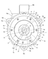
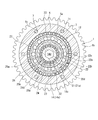
- FIG. 2 is a sectional view taken along the line AA of FIG. 1. It is a B arrow line view of FIG. It is a front view of the electric motor provided for the present embodiment.
- FIG. 2 is a sectional view taken along line CC of FIG. 1.
- the eccentric shaft used for this embodiment is shown, A is a side view of the eccentric shaft, B is a front view of the eccentric shaft, and C is a sectional view taken along line DD of B.
- valve timing control device It is a partial longitudinal cross-sectional view of the valve timing control device in a second embodiment of the present invention. It is a partial longitudinal cross-sectional view of a valve timing control device in a third embodiment of the present invention. It is a partial longitudinal cross-sectional view of the valve timing control device in a fourth embodiment of the present invention. It is a perspective view which shows the front cover provided for 4th Embodiment.
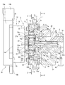
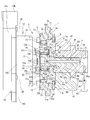
- FIG. 1 is a partial vertical cross-sectional view showing a valve timing control device according to this embodiment
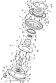
- FIG. 2 is an exploded perspective view showing main constituent members used in this embodiment
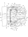
- FIG. 3 is a view of this embodiment shown in FIG.
- FIG. 4 is an enlarged view of a main part
- FIG. 4 is a sectional view taken along the line AA of FIG.
- valve timing control device is rotatably supported by a timing sprocket 1 (hereinafter referred to as sprocket 1), which is a driving rotating body, and a bearing 02 on a cylinder head 01.
- sprocket 1 a timing sprocket 1
- a camshaft 2 and a phase changing mechanism 3 that is arranged between the sprocket 1 and the camshaft 2 and that changes the relative rotational phase of the both 1, 2 according to the engine operating state are provided.
- the sprocket 1 is integrally formed of an iron-based metal, which is a metal material, in an annular shape.
- the sprocket body 1 a has an annular shape, and the sprocket body 1 a is integrally provided on the outer periphery of the sprocket body 1 a and wound around the outer periphery.
- a gear portion 1b that receives a rotational force from the crankshaft of the internal combustion engine via an external timing chain.
- a chain case (not shown) connected to the cylinder block of the internal combustion engine and the cylinder head 01 is provided on the outer periphery of the sprocket 1.
- an annular internal gear 5 that forms a part of a speed reducer 13 described later is integrally provided.
- the internal gear 5 is integrally connected to the sprocket body 1a in the rotation axis direction, and has a plurality of corrugated internal teeth 5a formed on the inner periphery thereof.
- the sprocket body 1a is provided with a slide bearing mechanism 6 between an inner peripheral surface of the sprocket body 1a and an outer peripheral surface of a driven member 9 which will be described later and is a driven rotating body fixed to one end 2a of the cam shaft 2 in the rotation axis direction. There is.
- the plain bearing mechanism 6 rotatably supports the sprocket 1 on the outer periphery of the driven member 9 (camshaft 2).
- a holding plate 8 is fixed to the rear end surface of the sprocket body 1a opposite to the internal gear 5 in the axial direction.
- the holding plate 8 is formed in an annular shape by a plate material of an iron-based metal which is a metal material, and its outer diameter is set to be substantially the same as the outer diameter of the sprocket body 1a.
- the holding plate 8 has a central hole 8a formed at the center thereof so that the inner peripheral portion 8b on the side of the central hole 8a covers one end opening on the cam shaft 2 side of a bearing recess 10 of the sliding bearing mechanism 6 which will be described later. It is located in.
- a portion serving as a hole edge of the central hole 8a is located inside the tooth bottom surface of the internal tooth 5a of the internal gear 5.
- the holding plate 8 is integrally provided with a stopper convex portion 8c projecting radially inward, that is, toward the central axis direction, at a predetermined position on the inner peripheral edge of the central hole 8a.
- the stopper projection 8c is formed in a substantially inverted trapezoidal shape, and the tip end surface is formed in an arc shape along the arc inner surface of the stopper groove 9f of the fixed end portion 9b of the driven member 9 described later. ..
- FIG. 5 is a view on arrow B of FIG.
- a front cover 15 which is a cover member, is provided on the front end surface of the sprocket 1 on the internal gear 5 side. As shown in FIGS. 1, 2 and 5, the front cover 15 is formed by punching an iron-based metal plate into a ring shape by press molding, and an eccentric shaft 21 described later is inserted and arranged in the center. An insertion hole 15a is formed therethrough.
- each outer peripheral portion of the sprocket body 1a including the internal gear 5 and the front cover 15 six bolt insertion holes 1c and 15b through which a plurality of (six in the present embodiment) bolts 7 are inserted are located at substantially equal intervals in the circumferential direction. Are formed to penetrate each. Further, the holding plate 8 is formed with six female screw holes 8d into which the male screw portions 7a at the tips of the bolts 7 are screwed, at positions corresponding to the bolt insertion holes 1c and 15b.
- two positioning pins 28a and 28b are inserted into the respective side portions of the two bolt insertion holes 1c of the sprocket body 1a and the corresponding two female screw holes 8d of the holding plate 8. Small holes 1d and 8e for positioning are provided respectively. By these, the holding plate 8 is positioned with respect to the sprocket 1 in the circumferential direction and the axial direction.
- the camshaft 2 has two drive cams per cylinder that open the intake valve (not shown) on the outer periphery. Further, the cam shaft 2 is integrally provided with a flange portion 2b for axially positioning via a bearing 02 at one end portion 2a on the phase changing mechanism 3 side in the rotation axis direction.
- the camshaft 2 also has an insertion hole 2c formed along the inner axial direction from the tip surface of the one end 2a.
- a shaft portion 14b of a cam bolt 14 to be described later is inserted into the insertion hole 2c, and a female screw portion 2d to which a male screw portion 14c of the cam bolt 14 is fastened is formed on a part of an inner peripheral surface of the one end portion 2a side. ..
- an oil supply passage 34 forming a part of a lubricating oil supply passage, which will be described later, for allowing the lubricating oil to flow therethrough is continuously formed inside the female screw portion 2d.
- a positioning pin 2g for positioning the driven member 9 in the rotational direction is press-fitted and fixed to the tip of the one end 2a of the camshaft 2 in the rotational axis direction.
- the driven member 9 is integrally formed of iron-based metal, and as shown in FIGS. 1 to 4, a disc-shaped body 9a and a circle integrally formed on the rear end side (camshaft 2 side) of the disc-shaped body 9a. It is mainly composed of an annular fixed end portion 9b.
- the disk-shaped main body 9a is integrally provided with a journal portion 11 forming a part of the slide bearing mechanism 6 on the outer peripheral surface. Further, the disk-shaped main body 9a is formed with a bolt insertion hole 9c through which an intermediate shaft portion 14g of a cam bolt 14, which will be described later, is inserted and fitted in the inner axial direction including the fixed end portion 9b.
- the bolt insertion hole 9c has an inner diameter larger than that of the insertion hole 2c of the camshaft 2.
- the fixed end 9b has a constant wall thickness and protrudes from the disc-shaped body 9a toward the camshaft 2. Further, the fixed end portion 9b has an annular fitting groove 9d into which the tip end of the one end portion 2a of the camshaft 2 fits, at approximately the center of the outer surface on the camshaft 2 side (outer peripheral side of the bolt insertion hole 9c). Has been formed. On the bottom surface of the fitting groove 9d, there is formed a positioning hole 9e into which the positioning pin 2g of the cam shaft 2 is inserted in the axial direction.
- the fixed end portion 9b is formed with a stopper concave groove 9f along the circumferential direction in which the stopper convex portion 8c of the holding plate 8 enters on the outer peripheral surface.
- the stopper groove 9f is formed in an arc shape having a predetermined length in the circumferential direction. Both side surfaces of the stopper convex portion 8c, which are rotated in the arcuate length range of the stopper concave groove 9f, respectively come into contact with the circumferential facing surfaces of the stopper concave groove 9f. As a result, the relative rotation position of the camshaft 2 with respect to the timing sprocket 1 on the maximum advance side or the maximum retard side is mechanically restricted.
- the driven member 9 is configured to be fastened and fixed to the camshaft 2 by the cam bolt 14 in the axial direction with the tip end of the one end 2a of the camshaft 2 fitted in the fitting groove 9d in the axial direction.
- the sliding bearing mechanism 6 is provided in an annular bearing recess 10 formed on the inner peripheral surface of the sprocket body 1 a and an outer peripheral surface of the disk-shaped main body 9 a. It has a journal portion 11 arranged inside and the holding plate 8 that covers one end opening of the bearing recess 10.
- the bearing recess 10 is formed only on the inner peripheral surface side of the sprocket body 1a, which is closer to the camshaft 2 side, without extending from one side surface of the sprocket body 1a on the holding plate 8 side to the internal gear 5. Further, as shown in FIG. 1, the bearing recess 10 has a substantially rectangular cross-sectional shape along the radial direction from the rotational axis of the sprocket 1, and a part thereof is formed at the formation position of each gear part 1b. It is arranged so as to overlap with the axial direction.
- the bearing recess 10 has a slide bearing surface 10a formed on the bottom surface of the annular shape. Further, in the bearing recess 10, an inner side surface 10b provided on the other end side opposite to the holding plate 8 in the axial direction is cut out from the sliding bearing surface 10a at a substantially right angle in the radial direction. As described above, the bearing recess 10 is opened to the outside by opening the other end portion on the camshaft 2 side, and the released other end opening is formed by the inner surface 8f of the inner peripheral portion 8b of the holding plate 8. Is covered.
- the journal portion 11 projects radially outward from the outer peripheral surface of the disk-shaped main body 9a and is formed in a rectangular shape whose cross-sectional shape is substantially similar to that of the bearing recess 10. Since the bearing recess 10 axially overlaps each gear portion 1b, the journal portion 11 is also partially axially overlapped with each gear portion 1b of the sprocket 1.
- journal portion 11 has annular grooves formed on both sides in the axial direction of the base portion 11a, which is a connecting portion with the disc-shaped main body 9a. Further, the journal portion 11 has an annular outer peripheral surface slidable over the sliding bearing surface 10 a of the bearing recess 10. Each annular groove prevents the journal portion from coming into contact with the inner side surface 8f of the holding plate 8 and the inner side surface 10b of the bearing recess 10 when the driven member 9 rotates.
- journal portion 11 is configured such that one end surface on the front cover 15 side in the axial direction can slide on the inner side surface 10b of the bearing recess 10.
- the inner side surface 10b comes into contact with one end surface of the journal portion 11 when the sprocket 1 is tilted, and restricts one thrust movement.
- the other end surface of the journal portion 11 on the side of the holding plate 8 in the axial direction is slidable on the inner side surface 8f of the inner peripheral portion 8b of the holding plate 8.
- the inner side surface 8f of the holding plate 8 comes into contact with the other end surface of the journal portion 11 when the sprocket 1 is tilted to regulate the thrust movement of the other.
- the cam bolt 14 is formed on a substantially cylindrical head portion 14a, a shaft portion 14b integrally fixed to the head portion 14a, and an outer peripheral surface of the shaft portion 14b.
- the male screw portion 14c screwed to the female screw portion 2d of the camshaft 2 is included.
- the head 14a has a hexagonal tool hole 14d formed at the tip to insert a tool such as a hexagon wrench. Further, the head 14a has a hardness higher than that of the other parts of the head 14a by subjecting the entire outer peripheral surface 14e to heat treatment such as induction hardening.
- the other portion is, for example, a seat surface 14f which is an axial side surface of the head portion 14a to which an intermediate shaft portion 14g of the shaft portion 14b described later is coupled. Further, each needle roller 25a of the needle bearing 25 is rotatably supported by the high hardness outer peripheral surface 14e of the head portion 14a.
- the seat surface 14f is located on the opposite surface outside the hole edge of the bolt insertion hole 9c of the disk-shaped body 9a of the driven member 9 when the male screw portion 14c of the cam bolt 14 is screwed into the female screw portion 2d of the cam shaft 2 and fastened. I am supposed to sit down.
- the shaft portion 14b is integrally provided with a large-diameter intermediate shaft portion 14g at the base of the head portion 14a, that is, in the center of the seat surface 14f in the axial direction of the head portion 14a.
- the outer diameter of the intermediate shaft portion 14g is larger than the outer diameter of the male screw portion 14c of the shaft portion 14b, and is slightly smaller than the inner diameter of the bolt insertion hole 9c of the driven member 9.
- the intermediate shaft portion 14g is inserted and fitted in the inner peripheral surface of the bolt insertion hole 9c with a minute clearance, and the coaxiality between the driven member 9 and the cam shaft 2 is ensured.
- the intermediate shaft portion 14g is inserted and fitted into the bolt insertion hole 9c to ensure the coaxiality between the driven member 9 and the camshaft 2.
- the insertion fitting of the intermediate shaft portion 14g into the bolt insertion hole 9c is a state close to a so-called intermediate fitting which is a mechanical fitting for ensuring the coaxiality between the driven member 9 and the cam shaft 2.
- the axial length of the intermediate shaft portion 14g is set to be substantially the same as the axial length of the bolt insertion hole 9c, and the tapered portion 14h is formed at the connecting portion of the shaft portion 14b with the male screw portion 14c. It is provided.
- An outer peripheral surface of the tapered portion 14h is formed so as to be inclined downward from the outer peripheral surface of the intermediate shaft portion 14g to the male screw portion 14c at a predetermined angle.
- an arcuate groove 14i is formed between the seat surface 14f of the head portion 14a and the intermediate shaft portion 14g (root portion). As shown in FIG. 3, the arcuate groove 14i is formed in an annular shape along the outer circumference of the intermediate shaft portion 14g.
- the cam bolt 14 when the cam bolt 14 is fastened to the camshaft 2 by the arcuate groove 14i, the seat surface 14f of the head portion 14a and the root of the intermediate shaft portion 14g are aligned with the hole edge of the bolt insertion hole 9c of the driven member 9. Is in a non-contact state without contact.
- the phase changing mechanism 3 is transmitted from the electric motor 12 arranged on the front end side of the fixed end portion 9b of the driven member 9 and the electric motor 12 via the Oldham coupling 20. It mainly comprises a speed reducer 13 that reduces the rotational speed and transmits it to the camshaft 2.
- FIG. 6 is a front view of the electric motor 12, and FIG. 7 is a sectional view taken along the line CC of FIG.
- the electric motor 12 is a so-called brushless DC type motor, and as shown in FIGS. 1, 2 and 6, a bottomed cylindrical motor housing 16 fixed to a chain case and a rear of the motor housing 16.
- a motor stator (not shown) which is provided at the end and accommodates a stator coil and the like inside, a motor shaft 17 arranged on the inner peripheral side of the stator coil, and a cylindrical shape fixed to the outer periphery of the motor shaft 17.
- a power feeding mechanism 18 provided at the front end of the motor housing 16 on the side opposite to the sprocket 1.
- the motor housing 16 is formed in a substantially cup shape, and a through hole (not shown) through which the motor shaft 17 is inserted is formed in substantially the center of the front end (bottom wall).
- a flange portion 16a protruding outward in the radial direction is integrally provided on the outer circumference of the rear end portion.
- the flange portion 16a is integrally provided with three bracket pieces 16b at a position of about 120° in the circumferential direction.
- bolt insertion holes 16c through which bolts for coupling to a chain case (not shown) are inserted are formed through the three bracket pieces 16b.
- each bolt 29 is adapted to connect the power feeding mechanism 18 to the motor housing 16.
- the motor stator is integrally formed mainly by a resin portion of synthetic resin material, and the stator coil is fixed inside the mold.
- the power feeding mechanism 18 has a box-shaped housing 18a made of a synthetic resin material. Inside the housing 18a, an energizing circuit such as a bus bar for supplying power to the electric motor 12, a rotation sensor for detecting the rotation position of the motor shaft 17, and the like are housed. Further, in the power feeding mechanism 18, a power feeding connector 18b electrically connected to a power feeding circuit and a signal connector (not shown) are integrally provided in the housing 18a.
- the power supply connector 18b has an internal terminal connected to a control unit (not shown) via a female terminal to a battery as a power source.
- the built-in terminal is connected to the control unit via the female terminal, and the rotation angle signal detected by the rotation sensor is output to the control unit.
- the motor shaft 17 is made of a metal material in a cylindrical shape, and has two width portions 17b and 17c formed along the tangential direction on the outer surface of the tip end 17a on the speed reducer 13 side. Further, as shown in FIG. 6, a pair of fitting grooves 17d and 17e are formed on the tip edge side of the tip portion 17a, the notch being cut out in a direction orthogonal to the two width portions 17b and 17c. A stopper member 19 for restricting the movement of the intermediate member 30 described later toward the cam bolt 14 is fitted and fixed in the both fitting grooves 17d and 17e in the radial direction.
- the motor shaft 17 is arranged such that the tip portion 17a is close to the head portion 14a of the cam bolt 14 with a slight clearance C from the rotation axis direction. Further, the entire tip portion 17a including the stopper member 19 can be inserted into the tool hole 14d from the axial direction.
- the stopper member 19 is formed in a C-ring shape, and is elastically deformable in the radial direction and the radial direction by its own elastic force.
- An intermediate member 30 is provided on the tip portion 17a of the motor shaft 17.
- the intermediate member 30 constitutes a part of the Oldham's joint 20, which is a joint connected to the speed reducer 13, and has a tubular shape fixed to the tip portion 17 a of the motor shaft 17, as shown in FIG. 6. It has a base 31.
- the tubular base portion 31 has a pair of flat portions 31a and 31b having a width across flats on both sides of the circular outer surface, that is, at a position of 180° in the circumferential direction, whereby the outer shape is substantially oval. Is formed in.
- a through hole 32 into which the tip portion 17a of the motor shaft 17 is inserted is formed at the center of the cylindrical base portion 31.
- the through hole 32 has a circular inner peripheral surface formed with a pair of facing surfaces 32 a and 32 b having a width across flat from the rotation axis of the motor shaft 17 in the radial direction. As a result, it is formed in an oval shape that is long in the radial direction and is similar to the outer shape of the tubular base 31. Therefore, the intermediate member 30 is movable in the radial direction (vertical direction in FIG. 6) with respect to the tip portion 17a of the motor shaft 17 via the oval through hole 32.
- the tubular base portion 31 is provided with two transmission keys 33a and 33b, which are a pair of projecting portions, at substantially central positions in the longitudinal direction (vertical direction in FIG. 6) of the pair of flat surface portions 31a and 31b.
- Each of the transmission keys 33a and 33b is formed in a substantially rectangular plate shape and protrudes radially outward from the two flat surface portions 31a and 31b of the tubular base portion 31.
- the speed reducer 13 is provided separately from the electric motor 12 in the axial direction, and each component is housed and arranged inside the sprocket 1 between the holding plate 8 and the front cover 15. ing.
- the speed reducer 13 includes a cylindrical eccentric shaft 21 which is an input shaft partially arranged inside the sprocket body 1a, and A ball bearing 22 which is a bearing provided on the outer circumference of the eccentric shaft 21, and a plurality of rollers 23 provided on the outer circumference of the ball bearing 22 and rotatably held in each internal tooth 5a of the internal gear 5,
- the driven member 9 is mainly provided with a retainer 24 which is integrally provided on the outer peripheral side of the disk-shaped body 9a and holds the plurality of rollers 23 in the rolling direction while permitting radial movement.
- FIG. 8 shows the eccentric shaft 21, A is a side view of the eccentric shaft 21, B is a front view of the eccentric shaft 21, and C is a sectional view taken along line DD of B.
- the eccentric shaft 21 includes an eccentric shaft portion 21a arranged on the outer periphery of a needle bearing 25, which is a bearing provided on the outer periphery of the head 14a of the cam bolt 14, And a large-diameter cylindrical portion 21b which is a connecting portion of the eccentric shaft portion 21a on the electric motor 12 side.
- the eccentric shaft portion 21a is formed in a cylindrical shape whose axial length is longer than the axial length of the needle bearing 25. Further, in the eccentric shaft portion 21a, the wall thickness t of the entire circumferential direction changes so that the shaft center X is slightly eccentric with respect to the shaft center Y of the cam bolt 14 (see FIGS. 2 and 8C).
- the large-diameter cylindrical portion 21b has a uniform thickness and is formed into a substantially circular shape, and is slightly thicker than the eccentric shaft portion 21a.
- the large-diameter cylindrical portion 21b projects from the inside of the sprocket body 1a toward the electric motor 12 through the insertion hole 15a of the front cover 15.
- the large-diameter cylindrical portion 21b constitutes the Oldham's joint 20 together with the intermediate member 30.
- the large-diameter cylindrical portion 21b is formed therein with a two-width-shaped fitting hole 21c into which the tubular base portion 31 of the intermediate member 30 can be fitted in the axial direction.
- the large-diameter cylindrical portion 21b is provided with a pair of crescent-shaped convex portions 21f and 21g forming a width across flats at a position of approximately 180° in the circumferential direction on the inner peripheral surface of the fitting hole 21c. Therefore, the inner peripheral surface of the fitting hole 21c is a large diameter portion, and the pair of convex portions 21f and 21g are configured as a small diameter portion.
- a pair of key grooves 21d and 21e into which the two transmission keys 33a and 33b of the tubular base portion 31 can be fitted in the rotational axis direction are provided at substantially the upper and lower central positions of the pair of convex portions 21f and 21g in FIG. 8B. Are formed.
- the key grooves 21d and 21e are formed in a rectangular shape similar to the transmission keys 33a and 33b, and the depth thereof is set to be substantially the same as the width of the transmission keys 33a and 33b.
- the pair of convex portions 21f and 21g function as a suppressing portion that suppresses excessive supply of the lubricating oil injected from the first oil hole 38 of the lubricating oil supply mechanism described later to the electric motor 12 (Oldham coupling 20). It has become.
- the needle bearing 25 is fixed to a plurality of needle rollers 25a rolling on the outer peripheral surface 14e of the head 14a of the cam bolt 14 and a stepped surface formed on the inner peripheral surface of the eccentric shaft portion 21a, and needle needles 25 are formed on the inner peripheral surface.
- a cylindrical shell 25b having a plurality of groove portions that rotatably hold the roller 25a.
- the ball bearings 22 are arranged in a state where they are substantially overlapped at the radial position of the needle bearing 25.
- the ball bearing 22 includes an inner ring 22a, an outer ring 22b, balls 22c interposed between the two wheels 22a and 22b, and a cage 22d holding the balls 22c.
- the inner ring 22a is press-fitted and fixed to the outer peripheral surface of the eccentric shaft portion 21a, while the outer ring 22b is in a free state without being fixed in the axial direction. That is, one end surface of the outer ring 22b on the electric motor 12 side in the axial direction is in a non-contact state with the inner surface of the front cover 15 via a minute clearance. Further, the other end surface of the outer ring 22b in the axial direction is also in a non-contact state with the back surface of the disk-shaped main body 9a of the driven member 9 facing it through a minute clearance.
- the outer ring 22b is in rollable contact with the outer peripheral surface of each roller 23. Further, an annular clearance is formed between the outer peripheral surface of the outer ring 22b and the inner surface of the cage 24. Therefore, the ball bearing 22 can be eccentrically moved in the radial direction along with the eccentric rotation of the eccentric shaft portion 21a via the clearance.
- the cage 24 is formed in a cylindrical shape and is integrally provided on the outer peripheral portion of the disk-shaped main body 9a. That is, the cage 24 linearly projects from the base portion 11a of the journal portion 11 of the disk-shaped main body 9a toward the front cover 15. A predetermined clearance is formed between the tip surface 24 a of the cage 24 and the inner surface of the front cover 15.
- the retainer 24 has a plurality of substantially rectangular roller holding holes 24b, which hold the plurality of rollers 23 rollably, respectively, formed along the axial direction.
- the plurality of roller holding holes 24b are provided at equidistant positions in the circumferential direction of the cage 24, and the tip end side is closed to form an elongated rectangular shape in the front-rear direction.
- the total number of roller holding holes 24b (the number of rollers 23) is smaller than the total number of teeth of the internal teeth 5a of the internal gear 5, so that a predetermined reduction ratio can be obtained. ing.
- Each roller 23 is made of iron-based metal, and is fitted into the internal teeth 5a of the internal gear 5 while moving in the radial direction due to the eccentric movement of the ball bearing 22. Further, each roller 23 is configured to swing in the radial direction while being guided in the circumferential direction by both side edges of each roller holding hole 24b.
- the reduction gear 13 and the Oldham coupling 20 described above are configured such that lubricating oil is supplied to the inside through a lubricating oil supply mechanism.
- the lubricating oil supply mechanism includes the oil supply passage 34 formed in the inner axial direction of the camshaft 2 and the bottom center of the tool hole 14d of the head 14a of the cam bolt 14. It has an oil passage hole 35 penetratingly formed along the inner axial direction of the shaft portion 14b, and an oil pump 36 for supplying lubricating oil to the oil supply passage 34.
- the oil supply passage 34 is formed long along the inner axial direction of the camshaft 2 and is also used as a means for supplying lubricating oil to a plurality of bearings (not shown) of the camshaft 2.
- the oil supply passage 34 communicates with the discharge passage 36a of the oil pump 36 via a supply hole 34a formed along the radial direction of the camshaft 2.
- the oil passage hole 35 includes a main passage hole 37 formed in a part of the head portion 14a of the cam bolt 14 and an inner axial direction of the shaft portion 14b, and an inner axial direction of the head portion 14a. And a first oil hole 38 which is formed on the lower end of the main passage hole 37 and communicates with the other end portion 37b on the downstream side of the main passage hole 37, and which communicates with the other end portion 37b of the main passage hole 37 that extends radially from the axial center of the head portion 14a. And a second oil hole 39.
- the main passage hole 37 is formed in a straight line along the axis of the cam bolt 14, and one upstream end portion 37 a opens into the oil supply passage 34 of the cam shaft 2.
- the other end portion 37b on the downstream side is located inside the head portion 14a and is connected to the first and second oil holes 38 and 39.
- the main passage hole 37 has a uniform inner diameter of about 2 mm.
- the upstream end of the first oil hole 38 is continuously connected to the other end 37b of the main passage hole 37 from the axial direction, while the first opening 38a at the downstream end opens to the tool hole 14d.
- the first opening 38a is adapted to supply a lubricating oil to the Oldham's joint 20 by being directed to a tip portion 17a of a motor shaft 17, which will be described later, from the axial direction.
- the inner diameter of the first oil hole 38 is set to about 1 mm, and the first oil hole 38 functions as an orifice narrowed down from the main passage hole 37. Therefore, as shown by the arrow in FIG.
- the lubricating oil that has flowed into the main passage hole 37 flows from the first opening portion 38a of the first oil hole 38 into the tip portion 17a of the motor shaft 17, that is, the tool hole 14d. It is injected, diffused from here, and supplied to the friction generation site of the Oldham's joint 20 and the speed reducer 13.
- the upstream end of the second oil hole 39 is connected to the other end 37b of the main passage hole 37 in the radial direction, and the downstream second opening 39a opens inside the speed reducer 13.
- the second opening 39a is directed from the radial direction to one axial end of the shell 25b of the needle bearing 25.
- the second oil hole 39 has an inner diameter set to about 1 mm like the first oil hole 38 and functions as an orifice narrowed down from the main passage hole 37 of about 2 mm. Therefore, the lubricating oil that has flowed into the main passage hole 37 is jetted from the second opening 39 a of the second oil hole 39 to the speed reducer 13. That is, the lubricating oil injected from the second opening 39a is supplied to the entire speed reducer 13 including the needle bearing 25, the ball bearing 22, the cage 24, and the like.
- the lubricating oil that has flowed into the speed reducer 13 from the second oil hole 39 passes through the inside of the ball bearing 22 and the retainer 24 on the outer peripheral side due to centrifugal force during driving, and from here, the bearing recess 10 is formed. And the journal portion 11. That is, the lubricating oil passes through between the both end surfaces and the outer peripheral surface of the journal portion 11 and the inner side surface 10b of the bearing recess 10 and the sliding bearing surface 10a to be used for lubrication.
- the oil pump 36 is a general pump such as a trochoid, and the discharge passage 36a communicates with a main oil gallery (not shown) that mainly supplies lubricating oil that lubricates the inside of the internal combustion engine.
- the control unit detects the current engine operating state based on information signals from various sensors such as a crank angle sensor, an air flow meter, a water temperature sensor, and an accelerator opening sensor (not shown), and controls the engine based on this. Is going.
- the control unit controls the rotation of the motor shaft 17 by energizing the coil portion based on the information signals and the rotational position detection mechanism, and controls the rotation phase of the camshaft 2 with respect to the timing sprocket 1 by the speed reducer 13. It is designed to be controlled. [Operation and effect of this embodiment] The operation of the valve timing control device in this embodiment will be described below.
- a control current from the control unit is supplied to the coil portion of the electric motor 12 to drive the motor shaft 17 in the forward and reverse directions.
- the rotational force of the motor shaft 17 is transmitted to the eccentric shaft 21 via the Oldham coupling 20 and the rotational force reduced by the operation of the speed reducer 13 is transmitted to the camshaft 2.
- each intake valve is controlled to convert the opening/closing timing to the advance side or the retard side.
- the inside of the Oldham coupling 20 and the speed reducer 13 can be effectively lubricated by the lubricating oil supply function.
- the lubricating oil discharged to the discharge passage 36a by the drive of the oil pump 36 is partially supplied to the inside of the engine from the main oil gallery, but the other part is supplied to the oil supply passage 34 from the supply hole 34a.
- the lubricating oil supplied to the oil supply passage 34 flows into the oil passage hole 35 from the one end 37a and the first oil hole 38 and the second oil hole 38 from the other end 37b, as shown by the arrows in FIGS. 1 and 3. It diverts to the oil hole 39.
- the lubricating oil in the first oil hole 38 is sprayed from the first opening 38a through the tool hole 14d to the tip portion 17a of the motor shaft 17 in the axial direction to collide and scatter.
- the scattered lubricating oil is supplied to the inside of the Oldham coupling 20.
- the lubricating oil injected from the first oil hole 38 partially passes through the clearance C by the centrifugal force and is partially supplied to the one end side of the needle bearing 25 on the electric motor 12 side in the axial direction, The other part goes around to the front end side of the eccentric shaft 21 and is supplied to the axial front end side of the ball bearing 22. As a result, the needle bearing 25 and the ball bearing 22 are lubricated.
- the lubricating oil injected from the first oil hole 38 is suppressed from scattering from the eccentric shaft 21 to the outside by the both convex portions 21f and 21g of the eccentric shaft 21. Therefore, it is efficiently supplied to the Oldham coupling 20 and the speed reducer 13.
- the lubricating oil that has flowed into the second oil hole 39 from the other end of the oil passage hole 35 is injected from the second opening 39a as shown by the arrow in FIG. Supplied to the department side. Further, from here, it is supplied to the axial rear end side of the ball bearing 22 by centrifugal force during driving, and is also supplied between each roller holding hole 24b of the holder 24 and each roller 23. Further, this lubricating oil is supplied between the sliding bearing surface 10a of the bearing recess 10 and the outer peripheral surface of the journal portion 11 by centrifugal force.
- the lubricity for the speed reducer 13 is further promoted and the lubricity for the bearing between the driven member 9 and the sprocket 1 is also improved.
- the lubricating oil supplied from the first and second oil holes 38 and 39 to the Oldham's joint 20 and the speed reducer 13 passes through the clearance C, the fitting hole 21c, etc. by centrifugal force, as shown by the arrow, The oil is discharged into the oil pan 45 from the insertion hole 15a of the cover 15.
- the lubricating oil supplied from the oil passage hole 35 to the first oil hole 38 and the second oil hole 39 is in an injection state due to the throttling function of both oil holes 38, 39, so an excessive supply amount is suppressed. To be done.
- the lubricating oil injected from the first oil hole 38 is prevented from excessive diffusion by the inner peripheral surface of the tool hole 14d and the both convex portions 21f and 21g of the fitting hole 21c. Therefore, it becomes possible to efficiently supply the lubricating oil to the Oldham coupling 20 and the speed reducer 13.
- the oil passage hole 35 of the lubricating oil supply mechanism is formed inside the cam bolt 14 instead of inside the cam shaft 2, so that the forming work is simplified and the work cost can be reduced.
- the camshaft 2 is simply provided with an existing oil supply passage 34 for lubricating the bearing of the camshaft 2.
- the oil passage hole 35 for lubricating the speed reducer 13 and the like is formed by the main passage hole 37a in the inner axial direction of the cam bolt 14 and the first and second oil holes 38, 39 in the radial direction. There is. That is, since the oil passage hole 35 can be formed only by drilling the cam bolt 14, for example, the working operation can be facilitated and the working cost can be reduced.
- the second oil hole 39 is formed inside the head portion 14a, not the shaft portion 14b of the cam bolt 14, it is possible to suppress the decrease in strength of the cam bolt 14.
- the intermediate member 14g causes the driven member 9 and the cam shaft 2 to be coaxial (alignment). Can be obtained.
- the intermediate shaft portion 14g is inserted into and fitted into the bolt insertion hole 9c in a substantially intermediate fit state, and the female screw portion 2d and the male screw portion 14c are fastened to each other, so that the driven member 9 and the cam shaft 2 are coaxial with each other. It will be possible to obtain.
- the seat surface 14f of the head portion 14a causes the peripheral surface of the hole on the electric motor 12 side of the bolt insertion hole 9c of the driven member 9 (the peripheral surface of the disk-shaped main body 9a). Press against. Even if the seat 14f side of the head 14a is buckled and deformed in the radial direction by this pressure, this deformation has little influence on the tightening torque. Therefore, it becomes possible to obtain a desired fastening torque by the cam bolt 14.
- the bolt insertion hole 9c of the driven member 9 is formed to have a relatively large diameter for inserting and fitting the intermediate shaft portion 14g having an inner diameter larger than the outer diameter of the shaft portion 14b (male screw portion 14c). Therefore, the cam bolt 14 can insert the shaft portion 14b into the bolt insertion hole 9c with a margin through the gap between the two portions 9c and 14b. Therefore, it is possible to prevent the external thread portion 14c from interfering with and damaging the hole edge of the bolt insertion hole 9c at the time of this insertion.
- the taper portion 14h provided on the tip side of the intermediate shaft portion 14g functions as a guide when the shaft portion 14b of the cam bolt 14 is inserted into the bolt insertion hole 9c. Therefore, the work of inserting the cam bolt 14 into the bolt insertion hole 9c becomes easy.
- the outer peripheral surface 14e of the head portion 14a is induction hardened to have high hardness, so that the following effects can be obtained.
- a reverse input to the reducer 13 acts on the cam bolt 14 due to the positive and negative alternating torque of the camshaft 2 generated while the engine is being driven, and a radial load is input to the outer peripheral surface 14e of the head 14a.
- the needle bearing 25 may interfere with the outer peripheral surface 14e of the head portion 14a.
- the outer peripheral surface 14e of the head 14a has a high hardness, it is possible to suppress the occurrence of damage.
- the bearing surface 14f of the head portion 14a has a hardness lower than that of the outer peripheral surface 14e, it is possible to sufficiently secure the fastening force of the cam bolt 14 due to the high toughness.
- the tip portion 17a (including the stopper member 19) of the motor shaft 17 of the electric motor 12 can be inserted into the tool hole 14d of the cam bolt 14 from the rotation axis direction. Therefore, when the motor shaft 17 or the cam shaft 2 (driven member 9) moves in the rotation axis direction due to the vibration of the engine or the like, the tip portion 17a of the motor shaft 17 enters the tool hole 14d to absorb the movement. it can. This makes it possible to shorten the axial distance between the motor shaft 17 and the cam bolt 14 as much as possible.
- the overall valve timing control device can be shortened in the axial direction, so the device can be downsized and the mountability in the engine room is improved.
- the intermediate member 30 can be moved in the radial direction with respect to the motor shaft 17 through the respective facing surfaces 32a and 32b of the through hole 32 and the two-face width portions 17b and 17c of the motor shaft tip portion 17a. ing. Further, the eccentric shaft 21 can be moved in the radial direction orthogonal to the radial movement of the intermediate member 30 via the two key grooves 21d and 21e and the two transmission keys 33a and 33b of the intermediate member 30.
- the inner side surface 8f of the inner peripheral portion 8b of the holding plate 8 contacts the other end surface of the journal portion 11 to receive and regulate the thrust load F2 in the other direction.
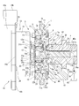
- FIG. 9 shows a second embodiment of the present invention, in which the motor shaft 17 of the electric motor 12 and the tubular base portion 31 of the Oldham coupling 20 are separated from the front end surface of the head portion 14a of the cam bolt 14 in the axial direction to form a gap C. Has a large axial width.
- the second oil hole 39 of the oil passage hole 35 is eliminated and only the first oil hole 38 is provided.
- Other configurations are the same as those in the first embodiment.
- the lubricating oil pressure-fed from the oil pump 36 to the main passage hole 37a of the oil passage hole 35 is injected from the first oil hole 38 to the tip portion 17a of the motor shaft 17 from the axial direction, as shown by the arrow in FIG. To be done.
- the injected lubricating oil collides with the tip portion 17a and scatters to lubricate the inside and outside of the tubular base 31, that is, the Oldham coupling 20.
- a part of the injected lubricating oil is supplied to one end portion of the needle bearing 25 in the axial direction through the clearance C by a centrifugal force or the like, and lubricates the inside of the needle bearing 25 while the ball bearing on the outer peripheral side. 22 is supplied inside.
- the lubricating oil is further supplied from here between the roller holding holes 24b on the outer peripheral side and the rollers 23, and is also supplied to the journal portion 11. Therefore, the friction generating parts such as the speed reducer 13 and the periphery of the journal 11 are effectively lubricated.
- the lubricating oil that lubricated the Oldham coupling 20 is discharged into the oil pan 45 as it is.
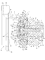
- FIG. 10 shows a third embodiment.
- a pair of passage grooves 40 and 41 are formed on the outer peripheral surface of the shaft portion 14b of the cam bolt 14, and a driven member is formed.
- An L-shaped communication hole 42 is formed in the inner peripheral portion of the member 9.
- the pair of passage grooves 40, 41 are formed at a position of approximately 180° in the circumferential direction of the shaft portion 14b, and are formed by linearly traversing the male screw portion 14c on the outer peripheral surface of the shaft portion 14b along the axial direction. It is provided in.
- the camshaft 2 has an annular groove groove 43 formed on the inner peripheral surface of the insertion hole 2c on the one end 2a side.
- Each of the passage grooves 40, 41 has one end portion 40 a, 41 a on the upstream side opening to the oil supply passage 34 of the camshaft 2, while the other end portion 40 b, 41 b on the downstream side opens to the groove groove 43. ..
- the communication hole 42 is provided with a radial hole 42a provided in the bottom surface of the fitting groove 9d of the driven member 9 so as to extend in the radial direction with respect to the rotation axis, and an axis formed through the disk-shaped body 9a in the rotation axis direction. And a direction hole 42b.
- the radial hole 42a is formed in an elongated groove shape, and one end on the inner side communicates with one end of the groove groove 43, and the other end on the outer side communicates with the axial hole 42b.
- the one end of the axial hole 42b opposite to the radial hole 42a is opened along the axial direction at the other end of the needle bearing 25 in the axial direction.
- the lubricating oil pressure-fed from the oil supply passage 34 to the passage grooves 40, 41 flows into the communication hole 42 via the groove groove 43 as shown by the arrow in the figure. Then, the lubricating oil flowing into the radial hole 42a of the communication hole 42 is injected from the axial hole 42b to the other end side of the needle bearing 25. After that, the lubricating oil is supplied to the outer ball bearing 22 by centrifugal force or the like, is further supplied between the roller holding hole 24b and the roller 23, and is further supplied around the journal portion 11. Therefore, each friction generating portion such as the speed reducer 13 is effectively lubricated.
- FIG. 11 shows a fourth embodiment, which has the same basic configuration as the second embodiment, but the structure of the front cover 15 which is a cover member is modified.
- the outer peripheral portion 15c of the front cover 15 is formed in a flat annular flange shape, but the inner peripheral portion 15d around the central insertion hole 15a bulges toward the electric motor 12 side. It is deforming. That is, the inner peripheral portion 15d is bent and deformed into a crank shape in a vertical cross section so as to project toward the electric motor 12, and the entire front cover 15 is formed in a bowl shape.
- the inner peripheral portion 15d is formed in a truncated cone shape, and the front end portion 15d on the insertion hole 15a side covers the outer periphery of the large-diameter cylindrical portion 21b of the eccentric shaft 21 via a predetermined gap C1.
- the lubricating oil pressure-fed from the oil pump 36 to the main passage hole 37a of the oil passage hole 35 is injected from the first oil hole 38 to the tip portion 17a of the motor shaft 17 from the axial direction, as shown by the arrow in FIG. To be done.
- the injected lubricating oil collides with the tip portion 17a and scatters to lubricate the inside and outside of the cylindrical base portion 31, that is, the Oldham coupling 20.
- a part of the injected lubricating oil is supplied to one end portion of the needle bearing 25 in the axial direction through the gap C by a centrifugal force or the like, and lubricates the inside of the needle bearing 25 while the ball bearing on the outer peripheral side. 22 is supplied inside. Further, the lubricating oil is supplied from here between the roller holding holes 24b on the outer peripheral side and the rollers 23, and is also supplied to the journal portion 11. Therefore, the friction generating parts such as the speed reducer 13 and the periphery of the journal 11 are effectively lubricated.
- the inner peripheral portion 15b of the front cover 15 functions as a guide and a trap for the lubricating oil, the supply amount of the lubricating oil such as the speed reducer 13 is increased and a higher lubricating performance is obtained.
- the reduction gear 13 may be, for example, a planetary gear device or the like.
- first and second oil holes 38 and 39 of each embodiment may be formed to have the same inner diameter as the oil passage hole 35, and conversely, the oil passage hole 35 may be formed to the first and second oil holes 38. , 39 and the same orifice-shaped small diameter.
- valve timing control device for an internal combustion engine based on the embodiment described above, for example, the following modes are conceivable.
- a driving rotary body to which the rotational force from the crankshaft is transmitted a driven rotary body that is provided so as to be rotatable relative to the driving rotary body, and is fixed to the camshaft,
- a reduction gear that is provided between the driving rotary body and the driven rotary body and rotates the input rotary shaft relative to the drive rotary body by rotating the input shaft, and rotates the input shaft via a joint.
- An electric motor having a motor shaft for driving, and a cam bolt for coupling the driven rotor to the cam shaft, the cam bolt communicating with a supply passage for supplying lubricating oil into the internal combustion engine, and at least one of the joint and the speed reducer.
- the cam bolt having an oil passage hole capable of supplying lubricating oil therein.
- the joint includes an intermediate member that is integrally rotatably held on the motor shaft, and a connecting portion that is provided on the input shaft and that is integrally rotatably connected to the intermediate member. ..
- the oil passage hole has an opening on the downstream side that opens in the axial direction so as to face the joint.
- the opening of the oil passage hole opens in the joint in the axial direction, lubricity to the joint is improved.
- the input shaft has a suppressing portion that suppresses excessive supply of lubricating oil from the oil passage hole to the electric motor side.
- the lubricating oil flowing out from the oil passage hole to the joint side can be prevented from being scattered to the outside by the suppressing portion, so that the lubricity of the joint and the speed reducer is improved.
- the suppressing portion is provided on the inner circumference of the input shaft, and includes a large-diameter portion provided on the camshaft side in the axial direction and a motor shaft side in the axial direction with respect to the large-diameter portion. And at least a part of the small diameter portion is formed to have a diameter smaller than the inner diameter of the large diameter portion.
- the cam bolt has a head portion whose seating surface can come into axial contact with the driven rotating body, and a bolt insertion hole formed in the driven rotating body extending from the seating surface in the cam shaft direction. And a male screw portion formed on the outer peripheral surface of the shaft portion and screwed into a female screw portion formed in the inner axial direction of the cam shaft, wherein the oil passage hole is ,
- a main passage hole provided mainly along the inner axial direction of the cam bolt from the tip end side of the shaft portion, and a main passage hole continuously provided along the inner axial direction of the head portion on the tip end side.
- a first oil hole having the opening and having an inner diameter smaller than the inner diameter of the main passage hole is provided.
- the lubricating oil flowing into the main passage hole is supplied from the first oil hole to the joint in an injection state. Moreover, the excessive supply of lubricating oil is suppressed by the throttling function of the first oil hole.
- the first oil hole is opened in a tool hole provided in the head of the cam bolt.
- the lubricating oil injected from the first oil hole through the opening diffuses in the tool hole, it is possible to supply it to the entire joint.
- the cam bolt has a head portion whose seating surface can come into axial contact with the driven rotating body, and a bolt insertion hole formed in the driven rotating body extending from the seating surface in the cam shaft direction. And a male screw portion formed on the outer peripheral surface of the shaft portion and screwed into a female screw portion formed in the inner axial direction of the cam shaft, wherein the oil passage hole is A main passage hole provided along the inner axial direction mainly from the tip side of the shaft portion of the cam bolt, and an inner radial direction of the head portion, one end of which communicates with the main passage hole, The other end has a second oil hole having a second opening opening toward the speed reducer.
- the lubricating oil that has flowed into the second oil hole from the main passage hole is directly supplied to the speed reducer from the second opening, so that the lubricating performance of the speed reducer is improved.
- the second oil hole is formed in the highly rigid head portion of the cam bolt, it is possible to suppress the decrease in strength of the cam bolt as compared with the case where the second oil hole is formed in the shaft portion or the male screw portion of the shaft portion.
- the second opening portion opens radially inward of the speed reducer.
- the lubricating oil that has flowed into the second oil hole from the main passage hole can be supplied to the reducer from the radially inner side through the second opening by utilizing the discharge pressure and the centrifugal force. , Can be sufficiently supplied to the speed reducer.
- a bearing forming a part of the speed reducer is provided between the outer peripheral surface of the head of the cam bolt and the inner peripheral surface of the input shaft, and the second opening of the second oil hole is The bearing is arranged closer to the contact portion between the bearing surface of the head and the driven rotating body than the center position of the bearing in the axial direction.
- the lubricating oil that has flowed into the second oil hole from the main passage hole can be directly supplied to the bearing of the speed reducer from the second opening. Therefore, it becomes possible to supply the lubricating oil to the bearing more efficiently than when supplying the lubricating oil from the tip end side of the head.
- the speed reducer includes an internal gear provided on an inner circumference of the drive rotating body, a bearing arranged on an outer circumference of the input shaft, and an outer circumference of the bearing and an inner tooth of the inner gear.
- a plurality of rolling elements arranged in the same manner, and a retainer that is provided integrally with the driven rotating body and holds the plurality of rolling elements at predetermined circumferential intervals, and the bearing and the oil passage hole are It is in communication.
- the lubricating oil supplied to the oil passage hole can be positively supplied to the bearing of the speed reducer via the oil passage hole, so that the lubrication performance of the bearing can be improved. ..
- a seat surface has a head portion that can come into contact with the driven rotor in the axial direction, and a bolt insertion hole formed in the driven rotor that extends from the seat surface in the cam shaft direction.
- a male screw portion formed on the outer peripheral surface of the shaft portion and screwed into a female screw portion formed in the inner axial direction of the cam shaft, wherein the oil passage hole is
- An opening at a downstream end opens to the electric motor side of the head, and the bearing has one end portion on the electric motor side in the axial direction of the bearing more than a front end portion of the head on the electric motor side in the axial direction. It is arranged near the electric motor.
- the lubricating oil flowing out from the downstream side opening through the oil passage hole scatters in the radial direction by the rotating centrifugal force and passes through the front end face of the head, and one end portion of the bearing. It will be collected by. This improves the lubricity of the bearing.
- the cam bolt is formed in the driven rotating body by extending from the seating surface of the head in the camshaft direction to a head having a seating surface that can come into contact with the driven rotating body in the axial direction.
- the oil passage hole has an opening at the downstream end that opens toward the electric motor of the head, and the drive rotor has at least a portion that covers the end of the input shaft on the electric motor side in the axial direction.
- the lubricating oil flowing out from the opening at the downstream end through the oil passage hole is scattered from the inner side of the head to the outer peripheral side by the centrifugal force, but a part of the scattered lubricating oil. Are collected on the inner surface of the cover member and supplied to the inside of the speed reducer. This improves the lubricity of parts such as the bearings and rollers of the speed reducer.
- a driving rotary body to which the rotational force from the crankshaft is transmitted, a driven rotary body fixed to a camshaft so as to be rotatable relative to the driving rotary body, and the driving rotary body
- a reduction gear that is provided between the body and the driven rotating body, and that rotates the input shaft by rotating the input shaft, and a motor shaft that rotates the input shaft via a joint.
- a cam bolt for coupling the driven rotating body to a cam shaft, the shaft portion having a male screw portion screwed into a female screw hole provided in the cam shaft inner axial direction, and the male screw portion.
- the cam bolt having a passage groove provided along the axial direction of the outer peripheral surface of the shaft portion for allowing lubricating oil to flow therethrough, and the driven rotor provided with the passage groove and the speed reducer communicating with each other. And a communication hole for connecting.
- the lubricating oil that has flowed into the passage groove formed on the outer peripheral surface of the shaft portion of the cam bolt can be supplied to the reduction gear through the communication hole.
- the forming work is easy because the passage groove along the axial direction is simply formed on the outer peripheral surface of the shaft portion (including the male screw portion) of the cam bolt. Therefore, the molding workability is improved and the cost can be reduced.
- the cam bolt has a head portion whose seating surface abuts on the driven rotor in the axial direction, and a bearing is provided between the outer circumference of the head portion and the inner circumference of the input shaft.
- the hole has a radial tip end position that is the same as the bearing or is located inside the bearing from the rotation axis of the driven rotor.
- the tip of the communication hole is located at the same position as or inside the bearing, it is easy to lubricate the bearing.
- the passage groove is provided across the thread of the male screw portion.
- Eccentric shaft input shaft
- 21a... Eccentric shaft Part 21b... Large-diameter cylindrical part (connecting part), 21c... Fitting hole (large-diameter part, suppressing part), 21g ⁇ 21f... Convex part (small-diameter part, suppressing part), 22... Ball bearing (bearing), 23 ... roller, 24... cage, 24b... roller holding hole, 25... needle bearing (bearing), 30... intermediate member, 31... cylindrical base, 34... oil supply passage, 37... oil passage hole 35a... main passage hole, 38... 1st oil hole, 38a... 1st opening part, 39... 2nd oil hole, 39a... 2nd opening part, 40*41... Passage groove, 42... Communication hole, 42a... Radial hole, 42b... Axial direction Hole.
Landscapes
- Engineering & Computer Science (AREA)
- Mechanical Engineering (AREA)
- General Engineering & Computer Science (AREA)
- Valve Device For Special Equipments (AREA)
- Lubrication Of Internal Combustion Engines (AREA)
Abstract
偏心軸21が回転することによってスプロケット1に対して従動部材9を相対回転させる減速機13と、オルダム継手20を介して偏心軸を回転させるモータ軸17を有する電動モータ12と、従動部材をカムシャフト2に結合させるカムボルト14と、を備えている。このカムボルトは、内部軸方向に貫通形成され、内燃機関の内部に潤滑油を供給する油供給通路34と連通する油通路孔35を有している。この油通路孔は、大径な主通路孔37aの下流側に小径な第1油孔38と第2油孔39を有し、この両油孔から噴射された潤滑油によってオルダム継手と減速機の少なくとも一方を直接的に潤滑するようになっている。
Description
本発明は、例えば吸気弁や排気弁の開閉タイミングを制御する内燃機関のバルブタイミング制御装置に関する。
従来の内燃機関のバルブタイミング制御装置としては、以下の特許文献1に記載されたものが知られている。
このバルブタイミング制御装置は、減速機として遊星歯車装置が用いられている。この遊星歯車装置への潤滑方法としては、メカポンプからカム軸の内部に形成された導入通路に吐出された潤滑油が、導入口を通じて潤滑室へと導入されるようになっている。これによって、潤滑室では、遊星歯車装置の摩擦発生部位に潤滑油が順次供給されるようになっている。
しかしながら、前記従来のバルブタイミング制御装置にあっては、前述のように、導入通路が、カム軸の一端部から内部へ回転軸心から外れた回転軸方向に沿って形成されている。このため、加工作業が煩雑になり、加工コストなどが高騰するおそれがある。
本発明は、前記従来の技術的課題に鑑みて案出されたもので、減速機へ潤滑油を供給するための油通路孔の加工作業の容易性とコストの低減化が図り得る内燃機関のバルブタイミング制御装置を提供することを一つの目的としている。
好ましい態様の一つとしては、とりわけ、駆動回転体と従動回転体との間に設けられ、入力軸が回転することによって前記駆動回転体に対して前記従動回転体を相対回転させる減速機と、継手を介して前記入力軸を回転させるモータ軸を有する電動モータと、
前記従動回転体をカムシャフトに結合させるカムボルトであって、内燃機関の内部に潤滑油を供給する供給通路と連通し、前記継手と前記減速機に潤滑油を供給可能な油通路孔を内部に有する前記カムボルトと、を備えたことを特徴としている。
前記従動回転体をカムシャフトに結合させるカムボルトであって、内燃機関の内部に潤滑油を供給する供給通路と連通し、前記継手と前記減速機に潤滑油を供給可能な油通路孔を内部に有する前記カムボルトと、を備えたことを特徴としている。
本発明の好ましい態様によれば、減速機への潤滑油を供給する油通路孔の加工作業が容易になり、コストの高騰を抑制できる。
以下、本発明に係る内燃機関のバルブタイミング制御装置の実施形態を図面に基づいて詳述する。なお、本実施形態では、バルブタイミング制御装置を吸気側に適用したものを示しているが、排気側に適用することも可能である。
〔第1実施形態〕
図1は本実施形態におけるバルブタイミング制御装置を示す一部縦断面図、図2は本実施形態に供される主要な構成部材を示す分解斜視図、図3は図1に示す本実施形態の要部拡大図、図4は図1のA-A線断面図である。
〔第1実施形態〕
図1は本実施形態におけるバルブタイミング制御装置を示す一部縦断面図、図2は本実施形態に供される主要な構成部材を示す分解斜視図、図3は図1に示す本実施形態の要部拡大図、図4は図1のA-A線断面図である。
バルブタイミング制御装置は、図1及び図2に示すように、駆動回転体であるタイミングスプロケット1(以下、スプロケット1という。)と、シリンダヘッド01上に軸受02を介して回転自在に支持されたカムシャフト2と、スプロケット1とカムシャフト2との間に配置されて、機関運転状態に応じて両者1,2の相対回転位相を変更する位相変更機構3と、を備えている。
スプロケット1は、全体が金属材である鉄系金属によって環状一体に形成されており、円環状のスプロケット本体1aと、このスプロケット本体1aの外周に一体に設けられて、外周に巻回された図外のタイミングチェーンを介して内燃機関のクランクシャフトから回転力を受ける歯車部1bと、を備えている。
なお、スプロケット1の外周には、内燃機関のシリンダブロックとシリンダヘッド01に結合された図外のチェーンケースが設けられている。
スプロケット本体1aの前端側には、後述する減速機13の一部を構成する円環状の内歯車5が一体に設けられている。この内歯車5は、スプロケット本体1aに回転軸方向から一体に結合されていると共に、内周に波形状の複数の内歯5aが形成されている。
スプロケット本体1aは、その内周面とカムシャフト2の回転軸方向の一端部2aに固定された従動回転体である後述する従動部材9の外周面との間に滑り軸受機構6が設けられている。この滑り軸受機構6は、従動部材9(カムシャフト2)の外周でスプロケット1を相対回転可能に軸受けしている。
さらに、スプロケット本体1aの内歯車5と軸方向で反対側の後端面には、保持プレート8が固定されている。この保持プレート8は、図1、図2及び図4に示すように、金属材である鉄系金属の板材によって円環状に形成され、外径がスプロケット本体1aの外径とほぼ同一に設定されている。また、保持プレート8は、中央に中央孔8aが貫通形成されて、この中央孔8a側の内周部8bが滑り軸受機構6の後述する軸受凹部10のカムシャフト2側の一端開口を覆うように配置されている。この内周部8bは、中央孔8aの孔縁となる部位が、内歯車5の内歯5aの歯底面よりも内側に位置している。
また、保持プレート8は、中央孔8aの内周縁の所定位置に、径方向内側、つまり中心軸方向に向かって突出したストッパ凸部8cが一体に設けられている。このストッパ凸部8cは、ほぼ逆台形状に形成されて、先端面が従動部材9の後述する固定端部9bのストッパ凹溝9fの円弧状内周面に沿った円弧状に形成されている。
図5は図1のB矢視図である。
また、スプロケット1の内歯車5側の前端面には、カバー部材であるフロントカバー15が設けられている。このフロントカバー15は、図1、図2及び図5に示すように、例えば鉄系金属板を円環状にプレス成形で打ち抜き形成されたもので、中央には後述する偏心軸21が挿入配置される挿入孔15aが貫通形成されている。
内歯車5を含むスプロケット本体1aとフロントカバー15の各外周部には、複数(本実施形態では6本)のボルト7が挿通する6つのボルト挿通孔1c、15bが周方向のほぼ等間隔位置にそれぞれ貫通形成されている。また、保持プレート8は、前記各ボルト挿通孔1c、15bに対応する位置に各ボルト7の先端部の雄ねじ部7aが螺着する6つの雌ねじ孔8dが形成されている。
なお、図2に示すように、スプロケット本体1aの2つのボルト挿通孔1cと保持プレート8の対応する2つの雌ねじ孔8dの各側部には、2つの位置決め用のピン28a、28bが挿入する位置決め用の小孔1d、8eがそれぞれ設けられている。これらによって、保持プレート8が、スプロケット1に対して周方向及び軸方向の位置決めがなされるようになっている。
カムシャフト2は、外周に図外の吸気弁を開作動させる一気筒当たり2つの駆動カムを有している。また、カムシャフト2は、回転軸方向の位相変更機構3側の一端部2aに軸受02を介して軸方向の位置決めを行うフランジ部2bが一体に設けられている。
また、カムシャフト2は、一端部2aの先端面から内部軸心方向に沿って形成された挿入孔2cを有している。この挿入孔2cは、後述するカムボルト14の軸部14bが挿入されると共に、一端部2a側の内周面の一部にカムボルト14の雄ねじ部14cが締結される雌ねじ部2dが形成されている。また、この挿入孔2cは、雌ねじ部2dよりも深い内部に、潤滑油を通流させる後述の潤滑油供給通路の一部を構成する油供給通路34が連続して形成されている。
さらに、カムシャフト2の一端部2aの先端には、従動部材9との回転方向の位置決めを行う位置決め用のピン2gが回転軸方向から圧入固定されている。
従動部材9は、鉄系金属によって一体に形成され、図1~図4に示すように、円盤状本体9aと、この円盤状本体9aの後端側(カムシャフト2側)に一体に有する円環状の固定端部9bと、から主として構成されている。
円盤状本体9aは、外周面に滑り軸受機構6の一部を構成するジャーナル部11が一体に設けられている。また円盤状本体9aは、固定端部9bを含む内部軸心方向に後述するカムボルト14の中間軸部14gが挿通嵌合されるボルト挿通孔9cが貫通形成されている。このボルト挿通孔9cは、内径がカムシャフト2の挿入孔2cの内径よりも大きく形成されている。
固定端部9bは、一定の肉厚を有して円盤状本体9aからカムシャフト2方向へ突出している。また、固定端部9bは、カムシャフト2側の外側面のほぼ中央(ボルト挿通孔9cの外周側)にカムシャフト2の一端部2aの先端部が嵌合する円環状の嵌合溝9dが形成されている。この嵌合溝9dの底面には、前述したカムシャフト2の位置決め用のピン2gが軸方向から挿入される位置決め用の孔9eが形成されている。
また、固定端部9bは、外周面に保持プレート8のストッパ凸部8cが入り込むストッパ凹溝9fが円周方向に沿って形成されている。このストッパ凹溝9fは、円周方向へ所定長さの円弧状に形成されている。ストッパ凸部8cは、ストッパ凹溝9fの円弧状の長さ範囲で回動した両側面がストッパ凹溝9fの周方向の対向面にそれぞれ当接するようになっている。これによって、タイミングスプロケット1に対するカムシャフト2の最大進角側、あるいは最大遅角側の相対回転位置を機械的に規制するようになっている。
また、従動部材9は、嵌合溝9dにカムシャフト2の一端部2aの先端部が軸方向から嵌合した状態で、カムボルト14によってカムシャフト2に軸方向から締結固定されるようになっている。
滑り軸受機構6は、図1及び図2に示すように、スプロケット本体1aの内周面に形成された円環状の軸受凹部10と、円盤状本体9aの外周面に設けられ、軸受凹部10の内部に配置されたジャーナル部11と、軸受凹部10の一端開口を覆う前記保持プレート8と、を有している。
軸受凹部10は、スプロケット本体1aの保持プレート8側の一方側面から内歯車5まで延びることなく、カムシャフト2側に寄ったスプロケット本体1aの内周面側のみに形成されている。また、軸受凹部10は、図1に示すように、スプロケット1の回転軸心から径方向に沿った断面形状がほぼ矩形状に形成されていると共に、その一部が各歯車部1bの形成位置と軸方向でオーバーラップするように配置されている。
さらに、軸受凹部10は、円環状の底面に滑り軸受面10aが形成されている。また、軸受凹部10は、軸方向で保持プレート8と反対側の他端側に有する内側面10bが滑り軸受面10aから径方向へほぼ直角に切欠されている。また、軸受凹部10は、前述したように、カムシャフト2側の他端部が開口されて外部に解放され、この解放された他端開口が保持プレート8の内周部8bの内側面8fによって覆われている。
ジャーナル部11は、円盤状本体9aの外周面から径方向外側へ突出して、断面形状が軸受凹部10の断面形状とほぼ相似形の矩形状に形成されている。また、このジャーナル部11は、軸受凹部10が各歯車部1bと軸方向でオーバーラップしていることから、同じく一部がスプロケット1の各歯車部1bと軸方向でオーバーラップ配置されている。
さらに、ジャーナル部11は、円盤状本体9aとの結合部位である基部11aの軸方向両側にそれぞれ円環溝が形成されている。また、ジャーナル部11は、環状の外周面が軸受凹部10の滑り軸受面10a全体に摺動可能になっている。各円環溝は、従動部材9の回転時においてジャーナル部が、保持プレート8の内側面8fと軸受凹部10の内側面10bと接触するのを回避するようになっている。
また、ジャーナル部11は、軸方向のフロントカバー15側の一端面が軸受凹部10の内側面10bに摺動可能になっている。この内側面10bは、スプロケット1の傾動時においてジャーナル部11の一端面に当接して一方のスラスト移動を規制するようになっている。
また、ジャーナル部11は、軸方向の保持プレート8側の他端面が保持プレート8の内周部8bの内側面8fに摺動可能になっている。この保持プレート8の内側面8fが、スプロケット1の傾動時においてジャーナル部11の他端面に当接して他方のスラスト移動を規制するようになっている。
カムボルト14は、図1~図3に示すように、ほぼ円柱状の頭部14aと、この頭部14aに一体に固定された軸部14bと、この軸部14bの外周面に形成されて、カムシャフト2の雌ねじ部2dに螺着する雄ねじ部14cと、を有している。
頭部14aは、先端部に六角レンチなどの工具が挿入される六角形の工具穴14dが形成されている。また、頭部14aは、外周面14e全体に高周波焼き入れなどの熱処理が施されて、硬度が頭部14aの他の部位よりも高くなっている。この他の部位とは、例えば、軸部14bの後述する中間軸部14gが結合された頭部14aの軸方向の側面である座面14fである。また、頭部14aの高硬度の外周面14eには、ニードルベアリング25の各ニードルローラ25aが転動可能に支持されている。座面14fは、カムボルト14の雄ねじ部14cをカムシャフト2の雌ねじ部2dにねじ込んで締結した際に、従動部材9の円盤状本体9aのボルト挿通孔9cの孔縁よりも外側の対向面に着座するようになっている。
軸部14bは、頭部14aとの付け根部、つまり、頭部14aの軸方向の座面14f中央に、大径な中間軸部14gが一体に設けられている。この中間軸部14gは、外径が軸部14bの雄ねじ部14cの外径よりも大きく形成されていると共に、従動部材9のボルト挿通孔9cの内径よりも僅かに小さく形成されている。これによって、中間軸部14gは、ボルト挿通孔9c内周面に微小クリアランスをもって挿入嵌合して、従動部材9とカムシャフト2との同軸性を確保するようになっている。
すなわち、中間軸部14gは、カムボルト14によって従動部材9をカムシャフト2に結合する際において、ボルト挿通孔9cに挿入嵌合することによって従動部材9とカムシャフト2の同軸性を確保するようになっている。したがって、中間軸部14gのボルト挿通孔9cに対する挿入嵌合とは、従動部材9とカムシャフト2との同軸性を確保するために機械的な嵌め合いであるいわゆる中間嵌めに近い状態であることをいう。
また、中間軸部14gは、その軸方向の長さがボルト挿通孔9cの軸方向の長さとほぼ同一に設定されていると共に、軸部14bの雄ねじ部14cとの結合箇所にテーパ部14hが設けられている。このテーパ部14hは、外周面が中間軸部14gの外周面から雄ねじ部14cに掛けて所定角度で下り傾斜状に形成されている。
また、頭部14aの座面14fと中間軸部14gとの間(付け根部)には、円弧状溝14iが形成されている。この円弧状溝14iは、図3に示すように、中間軸部14gの外周に沿った円環状に形成されている。カムボルト14は、円弧状溝14iによって、カムボルト14をカムシャフト2に締め付けた際に、頭部14aの座面14f及び中間軸部14gの付け根部が従動部材9のボルト挿通孔9cの孔縁とは接触することなく非接触状態になっている。
位相変更機構3は、図1及び図2に示すように、従動部材9の固定端部9bの前端側に配置された電動モータ12と、この電動モータ12からオルダム継手20を介して伝達された回転速度を減速してカムシャフト2に伝達する減速機13と、から主として構成されている。
図6は電動モータ12の正面図、図7は図1のC-C線断面図である。
電動モータ12は、いわゆるブラシレスの直流型モータであって、図1、図2及び図6に示すように、チェーンケースに固定される有底円筒状のモータハウジング16と、このモータハウジング16の後端部に設けられて、内部にステータコイルなどが収容された図外のモータステータと、ステータコイルの内周側に配置されたモータ軸17と、該モータ軸17の外周に固定された円筒状の永久磁石と、モータハウジング16のスプロケット1と反対側の前端部に設けられた給電機構18と、を有している。
モータハウジング16は、ほぼカップ状に形成されて、前端部(底壁)のほぼ中央にモータ軸17が挿通する図外の貫通孔が形成されている。一方、後端部の外周には、径方向外側に突出したフランジ部16aが一体に設けられている。このフランジ部16aは、円周方向の約120°位置に3つのブラケット片16bが一体に設けられている。また、この3つのブラケット片16bには、図外のチェーンケースに結合するためのボルトが挿通されるボルト挿通孔16cがそれぞれ貫通形成されている。
さらに、フランジ部16aの円周方向の各ブラケット片16bの間には、3つのボルト29が挿通する別異の3つのボルト挿通孔が形成されている。各ボルト29は、モータハウジング16に給電機構18を結合するようになっている。
なお、ボルト挿通孔16cやボルト29などは、さらに増加することも可能である。
モータステータは、主として合成樹脂材の樹脂部によって一体に形成されて、内部にステータコイルがモールド固定されている。
給電機構18は、合成樹脂材によってボックス状に形成されたハウジング18aを有している。このハウジング18aの内部には、電動モータ12へ給電するバスバーなどの通電回路やモータ軸17の回転位置を検出する回転センサなどが収容配置されている。また、給電機構18は、ハウジング18aに通電回路に電気的に接続される給電用コネクタ18bと図外の信号用コネクタが一体に設けられている。
給電用コネクタ18bは、内部の端子が図外のコントロールユニットに雌端子を介して電源であるバッテリーに接続されている。一方、信号用コネクタは、内蔵された端子がコントロールユニットに雌端子を介して接続され、回転センサで検出された回転角信号をコントロールユニットに出力するようになっている。
モータ軸17は、金属材によって円柱状に形成されて、減速機13側の先端部17aの外面には接線方向に沿って形成された二面幅部17b、17cを有している。また、先端部17aの先端縁側には、図6に示すように、二面幅部17b、17cに対して直交する方向から切り欠かれた一対の嵌着溝17d、17eが形成されている。この両嵌着溝17d、17eには、後述する中間部材30のカムボルト14側への移動を規制するストッパ部材19が径方向から嵌着固定されている。
また、モータ軸17は、図3にも示すように、先端部17aがカムボルト14の頭部14aに回転軸方向から僅かな隙間Cをもって近接配置されている。また、先端部17aは、ストッパ部材19を含めた全体が工具穴14dの内部に軸方向から挿入可能になっている。
ストッパ部材19は、Cリング状に形成されて、自身の弾性力によって拡径方向及び縮径方向へ弾性変形可能になっている。
また、モータ軸17の先端部17aには、中間部材30が設けられている。この中間部材30は、減速機13に接続される継手であるオルダム継手20の一部を構成するものであって、図6に示すように、モータ軸17の先端部17aに固定される筒状基部31を有している。この筒状基部31は、円形状の外面の両側、つまり円周方向の180°位置に二面幅状の一対の平面部31a、31bを有しており、これによって、外形がほぼ長円状に形成されている。
また筒状基部31の中央位置には、モータ軸17の先端部17aが挿入される貫通孔32が形成されている。
この貫通孔32は、円形状の内周面にモータ軸17の回転軸から径方向に沿った二面幅状の一対の対向面32a、32bが形成されている。これによって、筒状基部31の外形と相似形の径方向に長い長円形状に形成されている。したがって、中間部材30は、長円状の貫通孔32を介してモータ軸17の先端部17aに対して径方向(図6中、上下方向)へ移動可能になっている。
筒状基部31は、一対の平面部31a、31bの長手方向(図6の上下方向)のほぼ中央位置に、一対の突出部である2つの伝達キー33a、33bが設けられている。各伝達キー33a、33bは、ほぼ矩形板状に形成されて、筒状基部31の2つの平面部31a、31bから径方向外側に向かって突出している。
減速機13は、図1に示すように、電動モータ12とは軸方向から分離独立して設けられ、各構成部材が保持プレート8とフロントカバー15との間のスプロケット1の内部に収容配置されている。
具体的に説明すれば、減速機13は、図1~図3及び図7に示すように、スプロケット本体1aの内部に一部が配置された入力軸である円筒状の偏心軸21と、該偏心軸21の外周に設けられたベアリングであるボールベアリング22と、該ボールベアリング22の外周に設けられ、内歯車5の各内歯5a内に転動自在に保持された複数のローラ23と、従動部材9の円盤状本体9aの外周側に一体に設けられ、複数のローラ23を転動方向に保持しつつ径方向の移動を許容する保持器24と、から主として構成されている。
図8は偏心軸21を示し、Aは偏心軸21の側面図、Bは偏心軸21の正面図、CはBのD-D線断面図である。
偏心軸21は、図1~図3及び図8A~Cに示すように、カムボルト14の頭部14aの外周に設けられた軸受であるニードルベアリング25の外周に配置された偏心軸部21aと、該偏心軸部21aの電動モータ12側に有する連結部である大径円筒部21bと、を有している。
偏心軸部21aは、軸方向の長さがニードルベアリング25の軸方向の長さよりも長い円筒状に形成されている。また、偏心軸部21aは、周方向全体の肉厚tが厚薄変化して軸心Xがカムボルト14の軸心Yに対して僅かに偏心している(図2、図8C参照)。
大径円筒部21bは、均一な肉厚でほぼ真円状に形成されていると共に、偏心軸部21aよりも僅かに肉厚に形成されている。この大径円筒部21bは、スプロケット本体1aの内部からフロントカバー15の挿入孔15aを介して電動モータ12方向へ突出している。この大径円筒部21bは、中間部材30と共にオルダム継手20を構成している。
つまり、大径円筒部21bは、内部に中間部材30の筒状基部31が軸方向から嵌合可能な二面幅状の嵌合孔21cが形成されている。
大径円筒部21bは、嵌合孔21cの内周面の円周方向のほぼ180°の位置に、二面幅を構成する三日月状の一対の凸部21f、21gが設けられている。したがって、嵌合孔21cの内周面が大径部であり、一対の凸部21f、21gが小径部として構成されている。また、一対の凸部21f、21gの図8B中の上下のほぼ中央位置には、筒状基部31の2つの伝達キー33a、33bが回転軸方向から嵌合可能な一対のキー溝21d、21eが形成されている。この各キー溝21d、21eは、各伝達キー33a、33bと相似形の矩形状に形成されて、その深さが各伝達キー33a、33bの幅とほぼ同じ長さに設定されている。
一対の凸部21f、21gは、後述する潤滑油供給機構の第1油孔38から噴射された潤滑油を電動モータ12(オルダム継手20)への過剰な供給を抑制する抑制部として機能するようになっている。
ニードルベアリング25は、カムボルト14の頭部14aの外周面14eを転動する複数のニードルローラ25aと、偏心軸部21aの内周面に形成された段差面に固定されて、内周面にニードルローラ25aを転動可能に保持する複数の溝部を有する円筒状のシェル25bと、を有している。
ボールベアリング22は、図1に示すように、ニードルベアリング25の径方向位置で全体がほぼオーバーラップする状態に配置されている。また、ボールベアリング22は、内輪22aと、外輪22b、該両輪22a、22bとの間に介装されたボール22cと、該ボール22cを保持するケージ22dと、から構成されている。
内輪22aは、偏心軸部21aの外周面に圧入固定されているのに対して、外輪22bは、軸方向で固定されることなくフリーな状態になっている。つまり、この外輪22bは、軸方向の電動モータ12側の一端面がフロントカバー15の内側面に微小クリアランスを介して非接触状態になっている。また、外輪22bの軸方向の他端面も、これに対向する従動部材9の円盤状本体9aの背面に微小なクリアランスを介して非接触状態になっている。
外輪22bは、外周面に各ローラ23の外周面が転動可能に当接している。また、外輪22bの外周面と保持器24の内面との間に、円環状のクリアランスが形成されている。したがって、ボールベアリング22は、クリアランスを介して全体が偏心軸部21aの偏心回転に伴って径方向へ偏心動可能になっている。
保持器24は、円筒状に形成されて、円盤状本体9aの外周部に一体に設けられている。つまり、この保持器24は、円盤状本体9aのジャーナル部11の基部11aからフロントカバー15方向へ直線状に突出している。保持器24の先端面24aとフロントカバー15の内側面との間には、所定のクリアランスが形成されている。
また、保持器24は、複数のローラ23をそれぞれ転動自在に保持するほぼ長方形状の複数のローラ保持孔24bが軸方向に沿って形成されている。この複数のローラ保持孔24bは、保持器24の円周方向の等間隔位置に設けられ、先端部側が閉塞されて前後方向に細長い長方形状に形成されている。また、ローラ保持孔24bは、その全体の数(ローラ23の数)が内歯車5の内歯5aの全体の歯数よりも少なくなっており、これによって、所定の減速比を得るようになっている。
各ローラ23は、鉄系金属によって形成され、ボールベアリング22の偏心動に伴って径方向へ移動しつつ内歯車5の内歯5aに嵌入している。また各ローラ23は、各ローラ保持孔24bの両側縁によって周方向にガイドされつつ径方向へ揺動運動するようになっている。
また、前述した減速機13とオルダム継手20は、潤滑油供給機構を介して内部に潤滑油が供給されるようになっている。
すなわち、潤滑油供給機構は、図1及び図3に示すように、カムシャフト2の内部軸方向に形成された前記油供給通路34と、カムボルト14の頭部14aの工具穴14dの底面中央から軸部14bの内部軸心方向に沿って貫通形成された油通路孔35と、油供給通路34に潤滑油を供給するオイルポンプ36と、を有している。
油供給通路34は、カムシャフト2の内部軸心方向に沿って長く形成されて、カムシャフト2の図外の複数の軸受に対する潤滑油の供給手段としても用いられている。また、この油供給通路34は、カムシャフト2の半径方向に沿って形成された供給孔34aを介してオイルポンプ36の吐出通路36aに連通している。
油通路孔35は、図1及び図3に示すように、カムボルト14の頭部14aの一部と軸部14bの内部軸方向に形成された主通路孔37と、頭部14aの内部軸方向に形成されて主通路孔37の下流側の他端部37bと連通する第1油孔38と、頭部14aの軸心から径方向に延びて主通路孔37の他端部37bと連通する第2油孔39と、を備えている。
主通路孔37は、カムボルト14の軸心に沿って直線状に形成され、上流側の一端部37aがカムシャフト2の油供給通路34に開口している。一方、下流側の他端部37bは、頭部14aの内部に位置して、第1、第2油孔38、39に接続されている。また、この主通路孔37は、全体の内径が約2mmの均一径に設定されている。
第1油孔38は、上流端が主通路孔37の他端部37bに軸方向から連続的に接続されている一方、下流端の第1開口部38aが工具穴14dに開口している。この第1開口部38aは、後述するモータ軸17の先端部17aに軸方向から指向して、オルダム継手20に潤滑油を供給するようになっている。また、この第1油孔38は、内径が約1mm程度に設定されて、主通路孔37から絞り込まれたオリフィスとして機能するようになっている。よって、主通路孔37に流入した潤滑油は、図2の矢印で示すように、第1油孔38の第1開口部38aからモータ軸17の先端部17a、つまり、工具穴14dに対して噴射されて、ここから拡散してオルダム継手20や減速機13の摩擦発生部位に供給されるようになっている。
第2油孔39は、上流端が主通路孔37の他端部37bに径方向から接続されている一方、下流端の第2開口部39aが減速機13の内部に開口している。具体的には、この第2開口部39aは、ニードルベアリング25のシェル25bの軸方向の一端部に径方向から指向している。また、第2油孔39は、内径が第1油孔38と同じく約1mm程度に設定されて、約2mm程度の主通路孔37から絞り込まれたオリフィスとして機能するようになっている。よって、主通路孔37に流入した潤滑油は、第2油孔39の第2開口部39aから減速機13に対して噴射状に供給される。つまり、第2開口部39aから噴射された潤滑油は、ニードルベアリング25やボールベアリング22、保持器24などを含む減速機13全体に供給されるようになっている。
また、第2油孔39から減速機13の内部に流入した潤滑油は、駆動中の遠心力によって、ボールベアリング22の内部や外周側の保持器24内などを通り、ここから、軸受凹部10とジャーナル部11との間に流入する。つまり、潤滑油は、ジャーナル部11の両端面や外周面と軸受凹部10の内側面10bや滑り軸受面10aとの間を通って潤滑に供される。
オイルポンプ36は、トロコイドなどの一般的なポンプであって、吐出通路36aが主として内燃機関の内部を潤滑する潤滑油を供給する図外のメインオイルギャラリーに連通している。
コントロールユニットは、図外のクランク角センサやエアーフローメータ、水温センサ、アクセル開度センサなど各種のセンサ類からの情報信号に基づいて現在の機関運転状態を検出し、これに基づいて機関制御を行っている。また、コントロールユニットは、前記各情報信号や回転位置検出機構に基づいて、コイル部に通電してモータ軸17の回転制御を行い、減速機13によってカムシャフト2のタイミングスプロケット1に対する相対回転位相を制御するようになっている。
〔本実施形態の作用効果〕
以下、本実施形態におけるバルブタイミング制御装置の作用について説明する。
〔本実施形態の作用効果〕
以下、本実施形態におけるバルブタイミング制御装置の作用について説明する。
まず、機関のクランクシャフトの回転駆動に伴ってタイミングチェーンを介してタイミングスプロケット1が回転すると、この回転力が内歯車5に伝達される。この内歯車5の回転力が、各ローラ23から保持器24及び従動部材9を経由してカムシャフト2に伝達される。これによって、カムシャフト2の駆動カムが各吸気弁を開閉作動させる。
機関始動後の所定の機関運転時には、コントロールユニットからの制御電流が電動モータ12のコイル部に通電されてモータ軸17が正逆回転駆動される。このモータ軸17の回転力が、オルダム継手20を介して偏心軸21に伝達されて減速機13の作動によりカムシャフト2に対し減速された回転力が伝達される。
これによって、カムシャフト2が、タイミングスプロケット1に対して正逆相対回転して相対回転位相が変換される。したがって、各吸気弁は、開閉タイミングを進角側あるいは遅角側に変換制御されるのである。
このように、吸気弁の開閉タイミングが進角側あるいは遅角側へ連続的に変換されることによって、機関の燃費や出力などの機関性能の向上が図れる。
そして、本実施形態では、潤滑油供給機能によって、オルダム継手20や減速機13の内部を効果的に潤滑することができる。
すなわち、オイルポンプ36の駆動によって吐出通路36aに吐出された潤滑油は、一部がメインオイルギャラリーから機関内部に供給されるが、他の一部が供給孔34aから油供給通路34に供給される。
油供給通路34に供給された潤滑油は、図1及び図3の矢印で示すように、一端部37aから油通路孔35に流入して、他端部37bから第1油孔38と第2油孔39に分流する。この第1油孔38の潤滑油は、第1開口部38aから工具穴14dを介してモータ軸17の先端部17aに軸方向から噴射され衝突して飛散する。この飛散した潤滑油が、オルダム継手20の内部に供給される。つまり、筒状基部31の内周面とモータ軸17の先端部17aとの間や、各伝達キー33a、33bと偏心軸21のキー溝21d、21eとの間などの摩擦発生部位に供給されて、これら摩擦発生部位全体を効果的に潤滑する。これによって、オルダム継手20は、潤滑性能が向上して常時円滑な作動が得られる。
また、前述のように、第1油孔38から噴射された潤滑油は、遠心力により隙間Cを通って一部がニードルベアリング25の軸方向の電動モータ12側の一端部側に供給され、他の一部が偏心軸21の前端側に回り込んでボールベアリング22の軸方向前端側に供給される。これによって、ニードルベアリング25やボールベアリング22の潤滑に供される。
さらに、第1油孔38から噴射された潤滑油は、偏心軸21の両凸部21f、21gによって偏心軸21より外部への飛散が抑制される。このため、オルダム継手20や減速機13に対して効率良く供給される。
一方、油通路孔35の他端部から第2油孔39に流入した潤滑油は、図2の矢印で示すように、第2開口部39aから噴射されてニードルベアリング25の軸方向の他端部側に供給される。さらにここから駆動中の遠心力などによってボールベアリング22の軸方向後端側に供給されると共に、保持器24の各ローラ保持孔24bと各ローラ23との間に供給される。さらに、この潤滑油は、遠心力によって軸受凹部10の滑り軸受面10aとジャーナル部11の外周面の間に供給される。
このため、ニードルベアリング25やボールベアリング22、各ローラ保持孔24bと各ローラ23との間、並びに軸受凹部10の内面とジャーナル部11の外面全体の潤滑性が良好になる。
したがって、減速機13に対する潤滑性がさらに促進されると共に、従動部材9とスプロケット1との間の軸受に対する潤滑性も良好になる。
なお、第1、第2油孔38、39からオルダム継手20や減速機13に供給された潤滑油は、矢印に示すように、遠心力によって隙間Cや嵌合孔21cなどを通って、フロントカバー15の挿入孔15aからオイルパン45内に排出される。
また、油通路孔35から第1油孔38と第2油孔39に供給された潤滑油は、この両油孔38,39の絞り機能によって噴射状態になることから、過度な供給量が抑制される。
しかも、第1油孔38から噴射された潤滑油は、工具穴14dの内周面や嵌合孔21cの両凸部21f、21gによって過剰な拡散が抑制される。このため、潤滑油を、オルダム継手20や減速機13へ効率良く供給することが可能になる。
また、本実施形態では、潤滑油供給機構の油通路孔35を、カムシャフト2の内部ではなくカムボルト14の内部に形成したことから、その成形作業が簡単になり作業コストの低減化が図れる。
すなわち、カムシャフト2には、このカムシャフト2の軸受を潤滑するための既存の油供給通路34が形成されているだけである。換言すれば、減速機13などを潤滑するための油通路孔35は、カムボルト14の内部軸心方向の主通路孔37aと、径方向の第1、第2油孔38,39によって形成されている。つまり、カムボルト14に、例えばドリル加工を施すだけで油通路孔35を形成できるので、その加工作業が容易になり、加工コストの低減化が図れる。
また、第2油孔39は、カムボルト14の軸部14bではなく頭部14aの内部に形成したことから、カムボルト14の強度の低下を抑制できる。
また、本実施形態では、カムボルト14を従動部材9のボルト挿通孔9cを介してカムシャフト1に締結する際に、中間軸部14gによって従動部材9とカムシャフト2との同軸性(調心性)を得ることができる。
つまり、中間軸部14gが、ボルト挿通孔9cにほぼ中間ばめ状態で挿入嵌合すると共に、雌ねじ部2dと雄ねじ部14cを締結することによって、従動部材9とカムシャフト2との同軸性を得ることが可能になる。
また、カムボルト14を、所定の締め付けトルクで締め付けると、頭部14aの座面14fが、従動部材9のボルト挿通孔9cの電動モータ12側の孔の周面(円盤状本体9aの周面)に圧接する。この圧力によって、頭部14aの座面14f側が、たとえ径方向へ座屈変形したとしても、この変形による締め付けトルクへの影響が少ない。このため、カムボルト14による所望の締結トルクを得ることが可能になる。
また、従動部材9のボルト挿通孔9cは、内径が軸部14b(雄ねじ部14c)の外径より大径な中間軸部14gを挿入嵌合させるために比較的大径に形成されている。このため、カムボルト14は、軸部14bをボルト挿通孔9cに両者9c、14b間の隙間を介して余裕をもって挿入することができる。このため、この挿入時において雄ねじ部14cがボルト挿通孔9cの孔縁に干渉して損傷するのを抑制できる。
さらに、中間軸部14gの先端側に有するテーパ部14hは、カムボルト14の軸部14bをボルト挿通孔9cに挿入する際のガイドとして機能する。このため、カムボルト14のボルト挿通孔9cへの挿入作業が容易になる。
また、頭部14aと中間軸部14gとの間に形成された円弧状溝14iによって、カムボルト14の締め付け時において、頭部14aと中間軸部14gとの間の応力集中の発生を抑制できる。
また、本実施形態では、頭部14aの外周面14eに高周波焼き入れを施して高硬度にしたことから、以下のような作用効果が得られる。
すなわち、機関駆動中に発生するカムシャフト2の正負の交番トルクによって減速機13に逆入力がカムボルト14に作用して、頭部14aの外周面14eに径方向への荷重が入力される。これによって、頭部14aの外周面14eにニードルベアリング25が干渉するおそれがある。しかし、頭部14aの外周面14eは硬度が高いことから、損傷の発生を抑制できる。
一方、頭部14aの座面14fは、硬度が外周面14eよりも低いことから、高い靱性によりカムボルト14の締結力を十分に確保することができる。
また、電動モータ12のモータ軸17の先端部17a(ストッパ部材19を含む)が、カムボルト14の工具穴14dの内部に回転軸方向から挿入可能になっている。このため、機関の振動などによってモータ軸17やカムシャフト2(従動部材9)などが回転軸方向へ移動した際に、モータ軸17の先端部17aが工具穴14d内に入ってこの移動を吸収できる。これにより、モータ軸17とカムボルト14との軸方向の距離を可及的に短くすることが可能になる。
この結果、バルブタイミング制御装置は、全体の軸方向の長さを短くできるので装置の小型化が図れ、エンジンルーム内への搭載性が向上する。
また、中間部材30は、貫通孔32の各対向面32a、32bとモータ軸先端部17aの二面幅部17b、17cを介して、モータ軸17に対して径方向への移動が可能になっている。また、偏心軸21は、2つのキー溝21d、21eと中間部材30の2つの伝達キー33a、33bを介して中間部材30の径方向移動と直交する径方向の移動が可能になっている。
このため、オルダム継手20としての製造誤差や、モータ軸17や偏心軸21の回転時における径方向の誤差を効果的に吸収することができる。この結果、モータ軸17の回転力を従動部材9に効率良く伝達することが可能になる。
また、本実施形態では、回転駆動中においてスプロケット1に、従動部材9に対する傾き方向の力(スラスト荷重F1,F2)が発生すると(図1参照)、このスラスト荷重F1,F2をジャーナル部11によって受け止めることができる。したがって、スプロケット1の傾動を抑制することが可能になる。
すなわち、スプロケット1が、一方向へ傾動しようとすると、軸受凹部10の内側面10bがジャーナル部11の一端面に当接して一方向のスラスト荷重F1を受け止め規制する。
また、スプロケット1が他方向へ傾動しようとすると、保持プレート8の内周部8bの内側面8fがジャーナル部11の他端面に当接して他方向のスラスト荷重F2を受け止め規制する。
これによって、スプロケット1は、従動部材9に対する傾きを効果的に抑制される。
〔第2実施形態〕
図9は本発明の第2実施形態を示し、電動モータ12のモータ軸17とオルダム継手20の筒状基部31を、カムボルト14の頭部14aの前端面から軸方向へ離間させて、隙間Cの軸方向幅を大きく形成した。
〔第2実施形態〕
図9は本発明の第2実施形態を示し、電動モータ12のモータ軸17とオルダム継手20の筒状基部31を、カムボルト14の頭部14aの前端面から軸方向へ離間させて、隙間Cの軸方向幅を大きく形成した。
また、油通路孔35の第2油孔39を廃止して第1油孔38のみとしたものである。他の構成は、第1実施形態と同じである。
したがって、オイルポンプ36から油通路孔35の主通路孔37aに圧送された潤滑油は、図9の矢印で示すように、第1油孔38からモータ軸17の先端部17aに軸方向から噴射される。この噴射された潤滑油は、先端部17aに衝突して飛散し、筒状基部31の内外、つまり、オルダム継手20を潤滑する。
一方、前記噴射された潤滑油の一部は、遠心力などによって隙間Cを通ってニードルベアリング25の軸方向の一端部に供給され、このニードルベアリング25の内部を潤滑しつつ外周側のボールベアリング22の内部に供給される。潤滑油は、さらにここから外周側の各ローラ保持孔24bと各ローラ23との間に供給されると共に、ジャーナル部11にも供給される。したがって、減速機13やジャーナル部11周囲などの摩擦発生部位が効果的に潤滑される。
なお、オルダム継手20を潤滑した潤滑油は、そのままオイルパン45内に排出される。
他の作用効果は第1実施形態と同じであるが、本実施形態は、第2油孔39を廃止したことから、油通路孔35の加工作業がさらに容易になり、コストの低減化が図れる。
〔第3実施形態〕
図10は第3実施形態を示し、カムボルト14の内部に油通路孔を形成するのではなく、カムボルト14の軸部14bの外周面に一対の通路溝40、41が形成されると共に、従動部材9の内周部にL字形の連通孔42が形成されている。
〔第3実施形態〕
図10は第3実施形態を示し、カムボルト14の内部に油通路孔を形成するのではなく、カムボルト14の軸部14bの外周面に一対の通路溝40、41が形成されると共に、従動部材9の内周部にL字形の連通孔42が形成されている。
すなわち、一対の通路溝40、41は、軸部14bの円周方向のほぼ180°の位置であって、軸部14bの外周面の雄ねじ部14cを軸方向に沿って直線状に横切った形で設けられている。
また、カムシャフト2は、一端部2a側の挿入孔2cの内周面に円環状のグルーブ溝43が形成されている。
各通路溝40、41は、上流側の一端部40a、41aがカムシャフト2の油供給通路34に開口している一方、下流側の他端部40b、41bがグルーブ溝43に開口している。
連通孔42は、従動部材9の嵌合溝9dの底面に回転軸心に対して径方向に延びて設けられた径方向孔42aと、円盤状本体9aの回転軸方向に貫通形成された軸方向孔42bと、を有している。
径方向孔42aは、細長い溝状に形成されて、内側の一端がグルーブ溝43の一端部に連通し、外側の他端が軸方向孔42bに連通している。
軸方向孔42bは、径方向孔42aと反対側の一端部がニードルベアリング25の軸方向の他端部に軸方向に沿って開口している。
したがって、油供給通路34から各通路溝40,41に圧送された潤滑油は、図中矢印で示すように、グルーブ溝43内を介して連通孔42に流入する。そして、この連通孔42の径方向孔42aに流入した潤滑油は、軸方向孔42bからニードルベアリング25の他端部側に噴射される。その後、潤滑油は、遠心力などによって外側のボールベアリング22に供給され、さらにローラ保持孔24bとローラ23との間に供給され、さらにジャーナル部11周囲にも供給される。したがって、減速機13などの各摩擦発生部位を効果的に潤滑する。
よって、前記各実施形態と同様な作用効果が得られる。特に、この実施形態では、カムボルト14の軸部14bの外周に単に通路溝40,41を形成するだけであるから、この加工作業が容易であり、この加工コストの低減化が図れる。
〔第4実施形態〕
図11は第4実施形態を示し、基本構成は第2実施形態と同じであるが、カバー部材であるフロントカバー15の構造を変更したものである。
〔第4実施形態〕
図11は第4実施形態を示し、基本構成は第2実施形態と同じであるが、カバー部材であるフロントカバー15の構造を変更したものである。
フロントカバー15は、図12にも示すように、外周部15cが平坦な円環フランジ状に形成されているが、中央の挿入孔15aの周囲の内周部15dが電動モータ12側へ膨出変形させている。つまり、内周部15dを、電動モータ12方向へ突出するように縦断面クランク状に折曲変形させてフロントカバー15全体が碗状に形成されている。
内周部15dは、截頭円錐状に形成されて、挿入孔15a側の前端部15dが偏心軸21の大径円筒部21bの外周を所定の隙間C1を介して覆う状態になっている。
したがって、オイルポンプ36から油通路孔35の主通路孔37aに圧送された潤滑油は、図11の矢印で示すように、第1油孔38からモータ軸17の先端部17aに軸方向から噴射される。この噴射された潤滑油は、先端部17aに衝突して飛散し、筒状基部31の内外、つまり、オルダム継手20を潤滑する。
一方、前記噴射された潤滑油の一部は、遠心力などによって隙間Cを通ってニードルベアリング25の軸方向の一端部に供給され、このニードルベアリング25の内部を潤滑しつつ外周側のボールベアリング22の内部に供給される。さらに潤滑油は、ここから外周側の各ローラ保持孔24bと各ローラ23との間に供給されると共に、ジャーナル部11にも供給される。したがって、減速機13やジャーナル部11周囲などの摩擦発生部位が効果的に潤滑される。
また、ニードルベアリング25の一端部側に供給された潤滑油の一部は、遠心力によって隙間C1を通ってボールベアリング22方向へ案内される。これにより、ボールベアリング22やローラ23などの減速機13やジャーナル部11周囲の潤滑性がさらに向上する。
この実施形態では、フロントカバー15の内周部15bが、潤滑油の案内及び捕集として機能することから、減速機13などの潤滑油の供給量が多くなってさらに高い潤滑性能が得られる。
本発明は、前記各実施形態の構成に限定されるものではなく、例えば、減速機13としては例えば遊星歯車装置などであっても良い。
また、各実施形態の第1、第2油孔38,39は、油通路孔35と同じ内径に形成することも可能であり、逆に油通路孔35を、第1、第2油孔38、39と同じオリフィス状の小径とすることも可能である。
以上説明した実施形態に基づく内燃機関のバルブタイミング制御装置としては、例えば、以下に述べる態様のものが考えられる。
すなわち、本発明における好ましい態様としては、クランクシャフトからの回転力が伝達される駆動回転体と、前記駆動回転体に対して相対回転可能に設けられ、カムシャフトに固定される従動回転体と、前記駆動回転体と従動回転体との間に設けられ、入力軸が回転することによって前記駆動回転体に対して前記従動回転体を相対回転させる減速機と、継手を介して前記入力軸を回転させるモータ軸を有する電動モータと、前記従動回転体を前記カムシャフトに結合させるカムボルトであって、内燃機関の内部に潤滑油を供給する供給通路と連通し、前記継手と前記減速機の少なくとも一方に潤滑油を供給可能な油通路孔を内部に有する前記カムボルトと、を備えている。
さらに好ましくは、前記継手は、前記モータ軸に一体回転可能に保持された中間部材と、前記入力軸に設けられ、前記中間部材に一体回転可能に連結された連結部と、を有している。
さらに好ましくは、前記油通路孔は、下流側に前記継手に軸方向から対向して開口する開口部を有している。
この発明の態様によれば、油通路孔の開口部が、継手に軸方向から開口してことから継手への潤滑性が向上する。
さらに好ましくは、前記入力軸は、前記油通路孔から前記電動モータ側へ過剰な潤滑油の供給を抑制する抑制部を有している。
この発明の態様によれば、油通路孔から継手側へ流出した潤滑油は、抑制部によって外部へ飛散するのを抑制できるので、継手や減速機に対する潤滑性が向上する。
さらに好ましくは、前記抑制部は、前記入力軸の内周に有し、軸方向の前記カムシャフト側に設けられた大径部と、前記大径部よりも軸方向の前記モータ軸側のであって、少なくとも一部が前記大径部の内径よりも小径に形成された小径部と、によって構成されている。
さらに好ましくは、前記カムボルトは、座面が前記従動回転体に軸方向から当接可能な頭部と、前記座面から前記カムシャフト方向へ延びて、前記従動回転体に形成されたボルト挿入孔に挿入される軸部と、該軸部の外周面に形成されて、前記カムシャフトの内部軸方向に形成された雌ねじ部に螺着される雄ねじ部と、を有し、前記油通路孔は、前記カムボルトの主として前記軸部の先端側から内部軸方向に沿って設けられた主通路孔と、前記頭部の内部軸方向に沿って前記主通路孔に連続して設けられ、先端側に前記開口部を有すると共に、内径が前記主通路孔の内径よりも小さな第1油孔と、を備えている。
この発明の態様によれば、第1油孔が絞り機能を発揮することから、主通路孔内に流入した潤滑油が第1油孔から前記継手へ噴射状態で供給される。また、第1油孔の絞り機能によって過度な潤滑油の供給が抑制される。
さらに好ましくは、前記第1油孔は、前記カムボルトの頭部に有する工具穴に開口している。
この発明の態様によれば、第1油孔から開口部を介して噴射された潤滑油は、工具穴内で拡散するので、継手全体に供給することが可能になる。
さらに好ましくは、前記カムボルトは、座面が前記従動回転体に軸方向から当接可能な頭部と、前記座面から前記カムシャフト方向へ延びて、前記従動回転体に形成されたボルト挿入孔に挿入される軸部と、該軸部の外周面に形成されて、前記カムシャフトの内部軸方向に形成された雌ねじ部に螺着される雄ねじ部と、を有し、前記油通路孔は、前記カムボルトの主として前記軸部の先端側から内部軸方向に沿って設けられた主通路孔と、前記頭部の内部径方向に沿って設けられ、一端が前記主通路孔に連通する一方、他端が前記減速機に向かって開口する第2開口部を有する第2油孔と、を備えている。
この発明の態様によれば、主通路孔から第2油孔に流入した潤滑油は、第2開口部から減速機へ直接的に供給されることから、減速機の潤滑性能が向上する。また、第2油孔は、カムボルトの剛性高い頭部に形成されていることから、軸部や該軸部の雄ねじ部に形成される場合に比較してカムボルトの強度の低下を抑制できる。
さらに好ましくは、前記第2開口部は、前記減速機の径方向内側に開口している。
この発明の態様によれば、主通路孔から第2油孔に流入した潤滑油は、吐出圧と遠心力を利用して第2開口部から径方向内側から減速機に供給することができるので、減速機に対して十分に供給することができる。
さらに好ましくは、前記カムボルトの頭部の外周面と前記入力軸の内周面との間に、前記減速機の一部を構成する軸受を有し、前記第2油孔の第2開口部は、前記軸受の軸方向の中央位置よりも前記頭部の座面と前記従動回転体との接触部寄りに配置されている。
この発明の態様によれば、主通路孔から第2油孔に流入した潤滑油は、第2開口部から減速機の軸受に対して直接的に供給することができる。したがって、潤滑油を頭部の先端側から供給する場合よりも、効率良く軸受に供給することが可能になる。
さらに好ましくは、前記減速機は、前記駆動回転体の内周に設けられた内歯車と、前記入力軸の外周に配置されたベアリングと、該ベアリングの外周と前記内歯車の内歯との間に配置された複数の転動体と、前記従動回転体と一体に設けられ、前記複数の転動体を周方向の所定間隔で保持する保持器と、を有し、前記ベアリングと前記油通路孔が連通している。
この発明の態様によれば、油通路孔に供給された潤滑油を、前記油通路孔を介して減速機のベアリングに積極的に供給することができるので、該ベアリングの潤滑性能の向上が図れる。
さらに好ましくは、前記カムボルトは、座面が前記従動回転体に軸方向から当接可能な頭部と、前記座面から前記カムシャフト方向へ延びて、前記従動回転体に形成されたボルト挿入孔に挿入される軸部と、該軸部の外周面に形成されて、前記カムシャフトの内部軸方向に形成された雌ねじ部に螺着される雄ねじ部と、を有し、前記油通路孔は、下流端の開口部が前記頭部の前記電動モータ側に開口し、前記ベアリングは、軸方向の前記電動モータ側の一端部が前記頭部の軸方向の前記電動モータ側の前端部よりも前記電動モータ寄りに配置されている。
この発明の態様によれば、油通路孔を通って下流側開口部から流出した潤滑油は、回転遠心力で径方向へ飛散して前記頭部の前端面を通過して、ベアリングの一端部で捕集する形になる。これにより、ベアリングの潤滑性が向上する。
さらに好ましくは、前記カムボルトは、前記従動回転体に軸方向から当接可能な座面を有する頭部と、前記頭部の座面から前記カムシャフト方向へ延びて、前記従動回転体に形成されたボルト挿入孔に挿入される軸部と、該軸部の外周面に形成されて、前記カムシャフトの内部軸方向に形成された雌ねじ部に螺着される雄ねじ部と、を有し、前記油通路孔は、下流端の開口部が前記頭部の前記電動モータ側に開口し、前記駆動回転体は、少なくとも一部が前記入力軸の軸方向の前記電動モータ側の端部を覆うカバー部材を有している。
この発明の態様によれば、前記油通路孔を通って下流端の開口部から流出した潤滑油は、遠心力によって頭部の内側から外周側に飛散するが、この飛散した潤滑油の一部がカバー部材の内面で捕集されて減速機の内部に供給される。これにより、減速機の軸受やローラなどの部品の潤滑性が向上する。
別の好ましい態様としては、クランクシャフトからの回転力が伝達される駆動回転体と、前記駆動回転体に対して相対回転可能に設けられ、カムシャフトに固定される従動回転体と、前記駆動回転体と従動回転体との間に設けられ、入力軸が回転することによって前記駆動回転体に対して前記従動回転体を相対回転させる減速機と、継手を介して前記入力軸を回転させるモータ軸を有する電動モータと、前記従動回転体をカムシャフトに結合させるカムボルトであって、前記カムシャフト内部軸方向に設けられた雌ねじ孔に螺着する雄ねじ部が設けられた軸部と、この雄ねじ部を含む軸部の外周面の軸方向に沿って設けられ、潤滑油を通流させる通路溝と、を有する前記カムボルトと、前記従動回転体に設けられ、前記通路溝と前記減速機とを連通する連通孔と、を備えている。
この発明の態様によれば、カムボルトの軸部の外周面に形成された通路溝に流入した潤滑油は、連通孔を通って減速機に供給することができる。
特に、この発明では、単にカムボルトの軸部(雄ねじ部を含む)の外周面に軸方向に沿った通路溝を形成するだけであるから成形作業が簡単である。したがって、成形作業性が良好になりコストの低減化が図れる。
さらに好ましくは、前記カムボルトは、座面が前記従動回転体に軸方向から当接する頭部を有し、前記頭部の外周と前記入力軸の内周との間に軸受が設けられ、前記連通孔は、前記従動回転体の回転軸から径方向の先端位置が前記軸受と同じ位置か、前記軸受よりも内側に位置している。
この発明の態様によれば、連通孔の先端位置が軸受と同じかそれよりも内側に位置していることから、前記軸受に対して潤滑し易い。
さらに好ましくは、前記通路溝は、前記雄ねじ部のねじ山を横切って設けられている。
1…タイミングスプロケット(駆動回転体)、1a…スプロケット本体、1b…歯車部(外歯)、2…カムシャフト、2a…一端部、3…位相変更機構、8…保持プレート、9…従動部材(従動回転体)、9a…円盤状本体、9b…固定端部、11…ジャーナル部、12…電動モータ、13…減速機、14…カムボルト、14a…頭部、14b…軸部、14c…雄ねじ部、14e…外周面、14f…座面、14g…中間軸部、15…フロントカバー(カバー部材)、15a…挿入孔、15c…内周部、21…偏心軸(入力軸)、21a…偏心軸部、21b…大径円筒部(連結部)、21c…嵌合孔(大径部、抑制部)、21g・21f…凸部(小径部、抑制部)、22…ボールベアリング(軸受)、23…ローラ、24…保持器、24b…ローラ保持孔、25…ニードルベアリング(軸受)、30…中間部材、31…筒状基部、34…油供給通路、37…油通路孔35a…主通路孔、38…第1油孔、38a…第1開口部、39…第2油孔、39a…第2開口部、40・41…通路溝、42…連通孔、42a…径方向孔、42b…軸方向孔。
Claims (16)
- クランクシャフトからの回転力が伝達される駆動回転体と、
前記駆動回転体に対して相対回転可能に設けられ、カムシャフトに固定される従動回転体と、
前記駆動回転体と従動回転体との間に設けられ、入力軸が回転することによって前記駆動回転体に対して前記従動回転体を相対回転させる減速機と、
継手を介して前記入力軸を回転させるモータ軸を有する電動モータと、
前記従動回転体を前記カムシャフトに結合させるカムボルトであって、内燃機関の内部に潤滑油を供給する供給通路と連通し、前記継手と前記減速機の少なくとも一方に潤滑油を供給可能な油通路孔を内部に有する前記カムボルトと、
を備えたことを特徴とする内燃機関のバルブタイミング制御装置。 - 請求項1に記載の内燃機関のバルブタイミング制御装置において、
前記継手は、前記モータ軸に一体回転可能に保持された中間部材と、前記入力軸に設けられ、前記中間部材に一体回転可能に連結された連結部と、を有することを特徴とする内燃機関のバルブタイミング制御装置。 - 請求項2に記載の内燃機関のバルブタイミング制御装置において、
前記油通路孔は、下流側に前記継手に軸方向から対向して開口する開口部を有することを特徴とする内燃機関のバルブタイミング制御装置。 - 請求項3に記載の内燃機関のバルブタイミング制御装置において、
前記入力軸は、前記油通路孔から前記電動モータ側への潤滑油の供給を抑制する抑制部を有することを特徴とする内燃機関のバルブタイミング制御装置。 - 請求項4に記載の内燃機関のバルブタイミング制御装置において、
前記抑制部は、前記入力軸の内周に有し、軸方向の前記カムシャフト側に設けられた大径部と、前記大径部よりも軸方向の前記モータ軸側であって、少なくとも一部が前記大径部の内径よりも小径に形成された小径部と、によって構成されていることを特徴とする内燃機関のバルブタイミング制御装置。 - 請求項3に記載の内燃機関のバルブタイミング制御装置において、
前記カムボルトは、座面が前記従動回転体に軸方向から当接可能な頭部と、前記座面から前記カムシャフト方向へ延びて、前記従動回転体に形成されたボルト挿入孔に挿入される軸部と、該軸部の外周面に形成されて、前記カムシャフトの内部軸方向に形成された雌ねじ部に螺着される雄ねじ部と、を有し、
前記油通路孔は、前記カムボルトの主として前記軸部の先端側から内部軸方向に沿って設けられた主通路孔と、前記頭部の内部軸方向に沿って前記主通路孔に連続して設けられ、先端側に前記開口部を有すると共に、内径が前記主通路孔の内径よりも小さな第1油孔と、
を備えたことを特徴とする内燃機関のバルブタイミング制御装置。 - 請求項6に記載の内燃機関のバルブタイミング制御装置において、
前記第1油孔は、前記カムボルトの頭部に有する工具穴に開口していることを特徴とする内燃機関のバルブタイミング制御装置。 - 請求項1に記載の内燃機関のバルブタイミング制御装置において、
前記カムボルトは、座面が前記従動回転体に軸方向から当接可能な頭部と、前記座面から前記カムシャフト方向へ延びて、前記従動回転体に形成されたボルト挿入孔に挿入される軸部と、該軸部の外周面に形成されて、前記カムシャフトの内部軸方向に形成された雌ねじ部に螺着される雄ねじ部と、を有し、
前記油通路孔は、前記カムボルトの主として前記軸部の先端側から内部軸方向に沿って設けられた主通路孔と、前記頭部の内部径方向に沿って設けられ、一端が前記主通路孔に連通する一方、他端が前記減速機に向かって開口する第2開口部を有する第2油孔と、
を備えたことを特徴とする内燃機関のバルブタイミング制御装置。 - 請求項8に記載の内燃機関のバルブタイミング制御装置において、
前記第2開口部は、前記減速機の径方向内側に開口していることを特徴とする内燃機関のバルブタイミング制御装置。 - 請求項9に記載の内燃機関のバルブタイミング制御装置において、
前記カムボルトの頭部の外周面と前記入力軸の内周面との間に、前記減速機の一部を構成する軸受を有し、
前記第2油孔の第2開口部は、前記軸受の軸方向の中央位置よりも前記頭部の座面と前記従動回転体との接触部寄りに配置されていることを特徴とする内燃機関のバルブタイミング制御装置。 - 請求項1に記載の内燃機関のバルブタイミング制御装置において、
前記減速機は、前記駆動回転体の内周に設けられた内歯車と、前記入力軸の外周に配置されたベアリングと、該ベアリングの外周と前記内歯車の内歯との間に配置された複数の転動体と、前記従動回転体と一体に設けられ、前記複数の転動体を周方向の所定間隔で保持する保持器と、を有し、
前記ベアリングと前記油通路孔が連通していることを特徴とする内燃機関のバルブタイミング制御装置。 - 請求項11に記載の内燃機関のバルブタイミング制御装置において、
前記カムボルトは、座面が前記従動回転体に軸方向から当接可能な頭部と、前記座面から前記カムシャフト方向へ延びて、前記従動回転体に形成されたボルト挿入孔に挿入される軸部と、該軸部の外周面に形成されて、前記カムシャフトの内部軸方向に形成された雌ねじ部に螺着される雄ねじ部と、を有し、
前記油通路孔は、下流端の開口部が前記頭部の前記電動モータ側に開口し、
前記ベアリングは、軸方向の前記電動モータ側の一端部が前記頭部の軸方向の前記電動モータ側の前端部よりも前記電動モータ寄りに配置されていることを特徴とする内燃機関のバルブタイミング制御装置。 - 請求項1に記載の内燃機関のバルブタイミング制御装置において、
前記カムボルトは、前記従動回転体に軸方向から当接可能な座面を有する頭部と、前記頭部の座面から前記カムシャフト方向へ延びて、前記従動回転体に形成されたボルト挿入孔に挿入される軸部と、該軸部の外周面に形成されて、前記カムシャフトの内部軸方向に形成された雌ねじ部に螺着される雄ねじ部と、を有し、
前記油通路孔は、下流端の開口部が前記頭部の前記電動モータ側に開口し、
前記駆動回転体は、少なくとも一部が前記入力軸の軸方向の前記電動モータ側の端部を覆うカバー部材を有することを特徴とする内燃機関のバルブタイミング制御装置。 - クランクシャフトからの回転力が伝達される駆動回転体と、
前記駆動回転体に対して相対回転可能に設けられ、カムシャフトに固定される従動回転体と、
前記駆動回転体と従動回転体との間に設けられ、入力軸が回転することによって前記駆動回転体に対して前記従動回転体を相対回転させる減速機と、
継手を介して前記入力軸を回転させるモータ軸を有する電動モータと、
前記従動回転体をカムシャフトに結合させるカムボルトであって、前記カムシャフト内部軸方向に設けられた雌ねじ孔に螺着する雄ねじ部が設けられた軸部と、この雄ねじ部を含む軸部の外周面の軸方向に沿って設けられ、潤滑油を通流させる通路溝と、を有する前記カムボルトと、
前記従動回転体に設けられ、前記通路溝と前記減速機とを連通する連通孔とを備えたことを特徴とする内燃機関のバルブタイミング制御装置。 - 請求項14に記載の内燃機関のバルブタイミング制御装置において、
前記カムボルトは、座面が前記従動回転体に軸方向から当接する頭部を有し、
前記頭部の外周と前記入力軸の内周との間に軸受が設けられ、
前記連通孔は、前記従動回転体の回転軸から径方向の先端位置が前記軸受と同じ位置か、前記軸受よりも内側に位置していることを特徴とする内燃機関のバルブタイミング制御装置。 - 請求項15に記載の内燃機関のバルブタイミング制御装置において、
前記通路溝は、前記雄ねじ部のねじ山を横切って設けられていることを特徴とする内燃機関のバルブタイミング制御装置。
Priority Applications (1)
| Application Number | Priority Date | Filing Date | Title |
|---|---|---|---|
| JP2020571009A JPWO2020162016A1 (ja) | 2019-02-06 | 2019-12-04 | 内燃機関のバルブタイミング制御装置 |
Applications Claiming Priority (2)
| Application Number | Priority Date | Filing Date | Title |
|---|---|---|---|
| JP2019-019282 | 2019-02-06 | ||
| JP2019019282 | 2019-02-06 |
Publications (1)
| Publication Number | Publication Date |
|---|---|
| WO2020162016A1 true WO2020162016A1 (ja) | 2020-08-13 |
Family
ID=71948198
Family Applications (1)
| Application Number | Title | Priority Date | Filing Date |
|---|---|---|---|
| PCT/JP2019/047363 Ceased WO2020162016A1 (ja) | 2019-02-06 | 2019-12-04 | 内燃機関のバルブタイミング制御装置 |
Country Status (2)
| Country | Link |
|---|---|
| JP (1) | JPWO2020162016A1 (ja) |
| WO (1) | WO2020162016A1 (ja) |
Cited By (2)
| Publication number | Priority date | Publication date | Assignee | Title |
|---|---|---|---|---|
| CN120211904A (zh) * | 2023-12-27 | 2025-06-27 | 北京车和家汽车科技有限公司 | 增程式发动机及车辆 |
| WO2025140456A1 (zh) * | 2023-12-27 | 2025-07-03 | 北京车和家汽车科技有限公司 | 缸盖油路系统、增程式发动机、曲轴前端系统、减震结构、发动机以及车辆 |
Citations (7)
| Publication number | Priority date | Publication date | Assignee | Title |
|---|---|---|---|---|
| JPH02241914A (ja) * | 1989-03-14 | 1990-09-26 | Aisin Seiki Co Ltd | 弁開閉時期制御装置 |
| JPH062512A (ja) * | 1992-06-19 | 1994-01-11 | Mazda Motor Corp | エンジンのバルブタイミング制御装置 |
| JP2009293576A (ja) * | 2008-06-09 | 2009-12-17 | Hitachi Automotive Systems Ltd | 内燃機関のバルブタイミング制御装置 |
| JP2010090889A (ja) * | 2008-09-10 | 2010-04-22 | Ntn Corp | 可変バルブタイミング装置 |
| WO2018092390A1 (ja) * | 2016-11-18 | 2018-05-24 | アイシン精機株式会社 | 弁開閉時期制御装置 |
| US20180238200A1 (en) * | 2015-08-13 | 2018-08-23 | Thyssenkrupp Presta Teccenter Ag | Adjustable camshaft having a phase actuator |
| US20180283231A1 (en) * | 2015-10-28 | 2018-10-04 | Schaeffler Technologies AG & Co. KG | Camshaft Adjusting Device |
Family Cites Families (2)
| Publication number | Priority date | Publication date | Assignee | Title |
|---|---|---|---|---|
| JPH0528321Y2 (ja) * | 1988-09-30 | 1993-07-21 | ||
| JPH11141312A (ja) * | 1997-11-11 | 1999-05-25 | Unisia Jecs Corp | 内燃機関のバルブタイミング制御装置 |
-
2019
- 2019-12-04 JP JP2020571009A patent/JPWO2020162016A1/ja active Pending
- 2019-12-04 WO PCT/JP2019/047363 patent/WO2020162016A1/ja not_active Ceased
Patent Citations (7)
| Publication number | Priority date | Publication date | Assignee | Title |
|---|---|---|---|---|
| JPH02241914A (ja) * | 1989-03-14 | 1990-09-26 | Aisin Seiki Co Ltd | 弁開閉時期制御装置 |
| JPH062512A (ja) * | 1992-06-19 | 1994-01-11 | Mazda Motor Corp | エンジンのバルブタイミング制御装置 |
| JP2009293576A (ja) * | 2008-06-09 | 2009-12-17 | Hitachi Automotive Systems Ltd | 内燃機関のバルブタイミング制御装置 |
| JP2010090889A (ja) * | 2008-09-10 | 2010-04-22 | Ntn Corp | 可変バルブタイミング装置 |
| US20180238200A1 (en) * | 2015-08-13 | 2018-08-23 | Thyssenkrupp Presta Teccenter Ag | Adjustable camshaft having a phase actuator |
| US20180283231A1 (en) * | 2015-10-28 | 2018-10-04 | Schaeffler Technologies AG & Co. KG | Camshaft Adjusting Device |
| WO2018092390A1 (ja) * | 2016-11-18 | 2018-05-24 | アイシン精機株式会社 | 弁開閉時期制御装置 |
Cited By (2)
| Publication number | Priority date | Publication date | Assignee | Title |
|---|---|---|---|---|
| CN120211904A (zh) * | 2023-12-27 | 2025-06-27 | 北京车和家汽车科技有限公司 | 增程式发动机及车辆 |
| WO2025140456A1 (zh) * | 2023-12-27 | 2025-07-03 | 北京车和家汽车科技有限公司 | 缸盖油路系统、增程式发动机、曲轴前端系统、减震结构、发动机以及车辆 |
Also Published As
| Publication number | Publication date |
|---|---|
| JPWO2020162016A1 (ja) | 2021-12-02 |
Similar Documents
| Publication | Publication Date | Title |
|---|---|---|
| EP2415978B1 (en) | Variable valve timing device | |
| JPH1113426A (ja) | ローラ支持装置 | |
| KR101896672B1 (ko) | 밸브 타이밍 조정장치 | |
| JP2019007409A (ja) | 弁開閉時期制御装置 | |
| JP2012145037A (ja) | 内燃機関のバルブタイミング制御装置 | |
| JP2009293576A (ja) | 内燃機関のバルブタイミング制御装置 | |
| JP2010242721A (ja) | 内燃機関のバルブタイミング制御装置 | |
| JPWO2020162016A1 (ja) | 内燃機関のバルブタイミング制御装置 | |
| CN111043279B (zh) | 一种惰齿轮装置及发动机 | |
| JP2010138736A (ja) | 内燃機関のバルブタイミング制御装置 | |
| JP5180135B2 (ja) | 可変バルブタイミング装置およびこの可変バルブタイミング装置に組み込まれるローラ減速機 | |
| JP7256691B2 (ja) | 内燃機関のバルブタイミング制御装置 | |
| CN114402123A (zh) | 内燃机的气门正时控制装置 | |
| JP2024065122A (ja) | 内燃機関のバルブタイミング制御装置 | |
| JP2020056357A (ja) | 内燃機関のバルブタイミング制御装置 | |
| JP2024054435A (ja) | 内燃機関のバルブタイミング制御装置 | |
| WO2023101003A1 (ja) | 内燃機関のバルブタイミング制御装置 | |
| US20190078473A1 (en) | Electric phaser with orbiting eccentric gears | |
| WO2020090198A1 (ja) | 位相変更ユニット及びバルブタイミング変更装置 | |
| JP2021165547A (ja) | 内燃機関のバルブタイミング制御装置及び減速機 | |
| JP2024125442A (ja) | 内燃機関のバルブタイミング制御装置 | |
| JP2020033961A (ja) | 内燃機関のバルブタイミング制御装置 | |
| CN112840106B (zh) | 内燃机的气门正时控制装置 | |
| JP6817455B2 (ja) | 内燃機関のバルブタイミング制御装置 | |
| KR20130125768A (ko) | 내연기관의 캠축 조정기 |
Legal Events
| Date | Code | Title | Description |
|---|---|---|---|
| 121 | Ep: the epo has been informed by wipo that ep was designated in this application |
Ref document number: 19914451 Country of ref document: EP Kind code of ref document: A1 |
|
| ENP | Entry into the national phase |
Ref document number: 2020571009 Country of ref document: JP Kind code of ref document: A |
|
| NENP | Non-entry into the national phase |
Ref country code: DE |
|
| 122 | Ep: pct application non-entry in european phase |
Ref document number: 19914451 Country of ref document: EP Kind code of ref document: A1 |