WO2020158730A1 - セラミックノズルおよび巻線機 - Google Patents
セラミックノズルおよび巻線機 Download PDFInfo
- Publication number
- WO2020158730A1 WO2020158730A1 PCT/JP2020/002973 JP2020002973W WO2020158730A1 WO 2020158730 A1 WO2020158730 A1 WO 2020158730A1 JP 2020002973 W JP2020002973 W JP 2020002973W WO 2020158730 A1 WO2020158730 A1 WO 2020158730A1
- Authority
- WO
- WIPO (PCT)
- Prior art keywords
- ceramic nozzle
- peripheral surface
- roughness curve
- less
- roughness
- Prior art date
- Legal status (The legal status is an assumption and is not a legal conclusion. Google has not performed a legal analysis and makes no representation as to the accuracy of the status listed.)
- Ceased
Links
Images

Classifications
-
- B—PERFORMING OPERATIONS; TRANSPORTING
- B65—CONVEYING; PACKING; STORING; HANDLING THIN OR FILAMENTARY MATERIAL
- B65H—HANDLING THIN OR FILAMENTARY MATERIAL, e.g. SHEETS, WEBS, CABLES
- B65H54/00—Winding, coiling, or depositing filamentary material
- B65H54/02—Winding and traversing material on to reels, bobbins, tubes, or like package cores or formers
- B65H54/28—Traversing devices; Package-shaping arrangements
- B65H54/30—Traversing devices; Package-shaping arrangements with thread guides reciprocating or oscillating with fixed stroke
-
- B—PERFORMING OPERATIONS; TRANSPORTING
- B65—CONVEYING; PACKING; STORING; HANDLING THIN OR FILAMENTARY MATERIAL
- B65H—HANDLING THIN OR FILAMENTARY MATERIAL, e.g. SHEETS, WEBS, CABLES
- B65H57/00—Guides for filamentary materials; Supports therefor
- B65H57/12—Tubes
-
- H—ELECTRICITY
- H01—ELECTRIC ELEMENTS
- H01F—MAGNETS; INDUCTANCES; TRANSFORMERS; SELECTION OF MATERIALS FOR THEIR MAGNETIC PROPERTIES
- H01F41/00—Apparatus or processes specially adapted for manufacturing or assembling magnets, inductances or transformers; Apparatus or processes specially adapted for manufacturing materials characterised by their magnetic properties
- H01F41/02—Apparatus or processes specially adapted for manufacturing or assembling magnets, inductances or transformers; Apparatus or processes specially adapted for manufacturing materials characterised by their magnetic properties for manufacturing cores, coils, or magnets
- H01F41/04—Apparatus or processes specially adapted for manufacturing or assembling magnets, inductances or transformers; Apparatus or processes specially adapted for manufacturing materials characterised by their magnetic properties for manufacturing cores, coils, or magnets for manufacturing coils
- H01F41/06—Coil winding
- H01F41/082—Devices for guiding or positioning the winding material on the former
Definitions
- the present disclosure relates to a ceramic nozzle and a winding machine.
- a ceramic nozzle is used to guide the wire material for winding.
- Patent Document 1 proposes a ceramic nozzle having a through hole for guiding a wire and made of a brittle material such as ceramic.
- the ceramic nozzle of the present disclosure is provided with a through hole for guiding a wire rod along the axial direction, and cutting at a load length ratio of 25% in a roughness curve of an inner peripheral surface forming the through hole.
- the cutting level difference (R ⁇ c) in the roughness curve which represents the difference between the level and the cutting level at the load length ratio of 75% in the roughness curve, is 1.6 ⁇ m or less.
- the winding machine of the present disclosure uses the above ceramic nozzle.
- the schematic structure of the winding machine provided with the ceramic nozzle of this indication is shown, (a) is a top view and (b) is a side view. It is a schematic diagram which shows the state of the winding using the ceramic nozzle of this indication.
- (A) is a perspective view and (b) is sectional drawing containing an axis
- FIG. 1A and 1B show a schematic configuration of a winding machine including a ceramic nozzle of the present disclosure.
- FIG. 1A is a plan view and FIG. 1B is a side view.
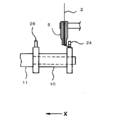
- FIG. 2 is a schematic diagram showing a winding state using the ceramic nozzle of the present disclosure.
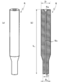
- FIG. 3 shows an example of the ceramic nozzle of the present disclosure, (a) is a perspective view, and (b) is a cross-sectional view including a shaft.
- the wire 2 supplied from the drum 1 is guided to the ceramic nozzle 5 made of a cylindrical body through the guide rollers 3 and 4, and the wire 2 guided to the ceramic nozzle 5 is The tip portion is clamped by the chuck 6.
- the ceramic nozzle 5 is provided with a through hole 5a for guiding the wire 2 along the axial direction, and the inner peripheral surface of the wire 2 on the supply port side and the discharge port side. Both of them are curved and expand in diameter.
- the ceramic nozzle 5 has, for example, a total length L 1 of 20 mm or more and 30 mm or less, an outer diameter D 1 of the wire 2 on the supply port side of 1.8 mm or more and 2 mm or less, and an outer diameter D 2 of the wire 2 on the discharge port side of 1 mm or more 1 0.4 mm or less, and the diameter D 3 of the through hole 5a is 0.05 mm or more and 0.15 mm or less.
- the ceramic nozzle 5 is supported by the block 9 via the plate 7 and the crank 8.
- the coil bobbin 10 for winding the wire 2 is installed so that the rotating shaft 11 for fixing the coil bobbin 10 at its tip is perpendicular to the axis of the ceramic nozzle 5.
- the ceramic nozzle 5 is rotated by the stroke of the air cylinder 12.
- the block 9 freely moves in the three-dimensional direction by the following mechanism, and the ceramic nozzle 5 also moves along with this movement.
- the block 9 is positioned in the X-axis direction by driving the pulse motor 13. Specifically, the block 9 is pushed and moved by the slide shaft 17 slidably supported by the frame 16 via the feed screw 14 and the block 15, and is positioned in the X-axis direction.
- the block 9 is driven by the pulse motor 18 in the Y-axis direction via the feed screw 19 and the block 20, and is driven by the pulse motor 21 in the Z-axis direction via the feed screw 22 and the slide block 23. Each is positioned.
- the position of the ceramic nozzle 5 in the three-dimensional direction is determined around the coil bobbin 10, and by this positioning, the winding work of the wire 2 on the coil bobbin 10 is performed as follows.
- the wire 2 which is given a tension between the ceramic nozzle 5 and the chuck 6 is inserted into the through hole 5a of the ceramic nozzle 5 and fixed to the first terminal 24 of the coil bobbin 10 as shown in FIG. It
- the rotary shaft 11 is rotationally driven by the pulse motor 25 via a pulley or the like, so that the coil bobbin 10 fixed to the tip end portion of the rotary shaft 11 rotates. Then, the wire rod 2 is wound around the coil bobbin 10. After the winding around the coil bobbin 10 is completed, the wire 2 is fixed to the second terminal 26.
- the ceramic nozzle 5 of the present disclosure included in the winding machine 30 illustrated in FIG. 1 has a cutting level at a load length ratio of 25% in the roughness curve of the inner peripheral surface 5b forming the through hole 5a, and the roughness.
- the cutting level difference (R ⁇ c) in the roughness curve which represents the difference from the cutting level at a load length ratio of 75% in the curve, is 1.6 ⁇ m or less.
- the cutting level C (Rrmr) corresponding to each of the two types of load length ratios corresponding to the load length ratio Rmr and the cutting level difference (R ⁇ c) indicating the difference between these cutting levels C (Rrmr) are also It corresponds to the surface height direction and the surface texture in the direction perpendicular to this height direction.
- the cutting level difference (R ⁇ c) is large, the unevenness on the surface to be measured is large, but when it is small, it can be said that the unevenness on the surface is small and relatively flat.
- the cutting level difference (R ⁇ c) is 1.6 ⁇ m or less, the irregularities on the inner peripheral surface 5b are small and relatively flat, so that shedding from the inner peripheral surface 5b is less likely to occur. As a result, even if the diameter of the through hole 5a becomes small, it is possible to suppress disconnection caused by grain shedding.
- the coefficient of variation of the cutting level difference (R ⁇ c) may be 0.3 or less.
- the coefficient of variation of the cutting level difference (R ⁇ c) is expressed by ⁇ V 1 /X 1, where the standard deviation of the cutting level difference (R ⁇ c) is ⁇ V 1 and the average value of the cutting level difference (R ⁇ c) is X 1. Value.
- the arithmetic mean roughness (Ra) in the roughness curve may be 1 ⁇ m or less.
- the arithmetic average roughness (Ra) is 1 ⁇ m or less, the unevenness of the inner peripheral surface 5b becomes smaller, so that shedding from the inner peripheral surface 5b becomes more difficult to occur, and the disconnection caused by this shedding can be suppressed. it can.
- the coefficient of variation of arithmetic mean roughness (Ra) may be 0.2 or less.
- the variation coefficient of the arithmetic average roughness (Ra) reduces the unevenness of the irregularities of the inner peripheral surface 5b, so that shedding from the inner peripheral surface 5b is more difficult to occur, and the effect of suppressing disconnection caused by this shedding is enhanced.
- both the cutting level difference (R ⁇ c) and the arithmetic average roughness (Ra) in the roughness curve have a laser microscope device having a measurement mode based on JIS B 0601:2001 (for example, manufactured by Keyence Corporation). (VK-9510)).
- the measurement mode is color super-depth
- the gain is 953
- the measurement magnification is 400 times
- the measurement range per location is 680 ⁇ m to 730 ⁇ m (axial direction) ⁇ 15 ⁇ m to 250 ⁇ m (circumferential direction).
- the measurement pitch is 0.05 ⁇ m
- the contour curve filter ⁇ s is 2.5 ⁇ m
- the contour curve filter ⁇ c is 0.08 mm.
- the number of measurement ranges is at least 8 at equal intervals on the inner peripheral surface 5b excluding the portion where the supply port side and the discharge port side of the wire are expanded, and the circumferential length is the same as that of the through hole 5a. It may be set so that the measurement range becomes wider according to the diameter.
- the skewness (R SK1 ) in the roughness curve along the axial direction of the inner peripheral surface 5b may be smaller than the skewness (R SK2 ) in the roughness curve in the circumferential direction of the outer peripheral surface.
- the skewness (R SK ) is defined in JIS B 0601:2001, and is an index indicating the ratio of peaks and valleys when the average height in the roughness curve is the center line.
- the flatness of the ridge portion on the inner peripheral surface 5b is higher than the flatness of the ridge portion on the outer peripheral surface 5c.
- the aggression of 5b is suppressed.
- the steepness of the ridges on the outer peripheral surface 5c is higher than the steepness of the ridges on the inner peripheral surface 5b. Therefore, when the outer peripheral surface 5c is bonded to the block 9 with an epoxy adhesive, the anchor effect is It is easy to obtain, and the reliability can be maintained even if the ceramic nozzle 5 vibrates.
- the arithmetic mean roughness (R a1 ) in the roughness curve along the axial direction of the inner peripheral surface 5 b and the arithmetic mean roughness (R a2 ) in the roughness curve along the circumferential direction of the outer peripheral surface are substantially equal.
- it also occurs in the case of 0.05 ⁇ m or more and 0.20 ⁇ m or less.
- the skewness (R SK1 ) is ⁇ 0.8 or more and 0.8 or less
- the skewness (R SK2 ) is 1 or more and 2 or less.
- the skewness (R SK1 ) is preferably 0 or a negative value, and the skewness (R SK2 ) is preferably a positive value.
- the aggressiveness of the inner peripheral surface 5b against the wire 2 is further suppressed and the reliability is improved.
- the skewness (R SK1 , R SK2 ) and the arithmetic mean roughness (R a1 , R a2 ) in the roughness curve are both laser microscopes having a measurement mode based on JIS B 0601:2001 ((shares)). It can be measured using VK-X1100 manufactured by Keyence or its successor model).
- the magnification is 480 times
- the cutoff value ⁇ s is not set
- the cutoff value ⁇ c is 0.08 mm
- the cutoff value ⁇ f is not set
- the measurement range for each spot is set to 705 ⁇ m ⁇ 530 ⁇ m.
- a representative portion showing the characteristics of the surface may be selected from the surface observed at a magnification of 480 times. Then, three lines to be measured are drawn along the longitudinal direction of the inner peripheral surface 5b and along the lateral direction of the outer peripheral surface 5c at substantially equal intervals for each measurement range. The line roughness may be measured for each line and the skewness (R SK1 ) and the skewness (R SK2 ) may be compared in nine combinations.
- the measured length on the outer peripheral surface 5c is 380 ⁇ m
- the measured length on the inner peripheral surface 5b is 550 ⁇ m.
- the ceramic nozzle of the present disclosure is, for example, a nozzle made of ceramics containing zirconium oxide, aluminum oxide, silicon carbide or silicon nitride as a main component.
- the main component in ceramics is a component that accounts for 70% by mass or more of the total 100% by mass of the components that make up the ceramics.
- the components forming the ceramics may be identified by using an X-ray diffraction device (XRD).
- XRD X-ray diffraction device
- the content of each component after identifying the component, the content of the element constituting the component is obtained by using a fluorescent X-ray analyzer (XRF) or an ICP emission spectroscopy analyzer, and converted to the identified component. Good.
- zirconium oxide is the main component, at least one selected from yttrium oxide (Y 2 O 3 ), cerium oxide (CeO 2 ), magnesium oxide (MgO), neodymium oxide (Nd 2 O 3 ) and calcium oxide (CaO). It may contain seeds.
- aluminum oxide When aluminum oxide is the main component, it may contain at least one selected from silicon oxide (SiO 2 ), magnesium oxide (MgO) and calcium oxide (CaO).
- a yttrium oxide powder is used in a total of 100 mol% of zirconium oxide powder and yttrium oxide powder. Is adjusted to be 2 mol% or more and 4 mol% or less.
- oxidation of the powder of the ceramic raw material and the Group 2 element is performed.
- the powder of the oxide of the Group 2 element is mixed in an amount of 8 mol% or more and 12 mol% or less in 100 mol% of the total powder of the product.
- the average particle size (D 50 ) of zirconium oxide is, for example, 0.1 ⁇ m or more and 1 ⁇ m or less.
- a thermoplastic resin such as isobutyl methacrylate (iBMA), isobutyl methacrylate (iBMA), polystyrene, paraffin wax, microwax, etc. is added as a binder to the prepared raw materials, and the mixture is kneaded using a kneading machine to be plasticized. A compounded mixture is obtained.
- the kneading device is, for example, a pressure kneader, and kneading may be performed at a temperature of about 140 to 160°C.
- the plasticized mixture After completion of the kneading, the plasticized mixture is put into an extruder which is heated to a temperature at which the plasticized mixture is softened to obtain a tubular molded body.
- the inner peripheral surface that forms the through-hole of the ceramic nozzle approximately copies the outer peripheral surface of the mandrel (core metal) installed in the extrusion molding machine in order to obtain a molded body.
- the difference between the cut level at a 25% load length ratio in the roughness curve and the cut level at a 75% load length ratio in the roughness curve is expressed as:
- a mandrel (core bar) having an outer peripheral surface with a cutting level difference (R ⁇ c) in the roughness curve of 1.6 ⁇ m or less is used.
- the variation coefficient of the cutting level difference (R ⁇ c) in the roughness curve of the outer peripheral surface of the mandrel (core metal) is set to 0. It may be set to 3 or less.
- the arithmetic average roughness (Ra) in the roughness curve of the outer peripheral surface of the mandrel (core) should be 1 ⁇ m or less. Good.
- the coefficient of variation of arithmetic average roughness (Ra) in the roughness curve of the outer peripheral surface of the mandrel (core) is calculated. It may be 0.2 or less.
- a cylindrical sintered body can be obtained by sequentially degreasing and firing the obtained molded body.
- the firing atmosphere may be an air atmosphere
- the firing temperature may be 1300° C. or higher and 1700° C. or lower
- the holding time may be 2 hours or longer and 4 hours or shorter.
- the ceramic nozzle of the present disclosure can be obtained by subjecting both end surfaces of the obtained sintered body to grinding.
- the inner peripheral surface is fired.
- the outer peripheral surface may be subjected to centerless processing along the radial direction.
- the outer peripheral surface is subjected to centerless processing along the radial direction, and JIS R 6001- An abrasive having a grain size specified by 2:2017 and having a grain size of #240 or less may be used.
Landscapes
- Engineering & Computer Science (AREA)
- Power Engineering (AREA)
- Manufacturing & Machinery (AREA)
- Guides For Winding Or Rewinding, Or Guides For Filamentary Materials (AREA)
- Mechanical Coupling Of Light Guides (AREA)
Abstract
本開示のセラミックノズルは、軸方向に沿って、線材を案内するための貫通孔を備え、前記貫通孔を形成する内周面の粗さ曲線における25%の負荷長さ率での切断レベルと、前記粗さ曲線における75%の負荷長さ率での切断レベルとの差を表す、前記粗さ曲線における切断レベル差(Rδc)が1.6μm以下である。
Description
本開示は、セラミックノズルおよび巻線機に関する。
従来、高周波コイル等のインダクタに巻線を行う自動巻線機では、巻線用の線材を案内するためのセラミックノズルが用いられている。
このようなセラミックノズルとして、特許文献1では、線材を案内するための貫通孔を備え、セラミック等の脆性材料からなるセラミックノズルが提案されている。
本開示のセラミックノズルは、軸方向に沿って、線材を案内するための貫通孔を備えてなり、前記貫通孔を形成する内周面の粗さ曲線における25%の負荷長さ率での切断レベルと、前記粗さ曲線における75%の負荷長さ率での切断レベルとの差を表す、前記粗さ曲線における切断レベル差(Rδc)が1.6μm以下である。
本開示の巻線機は、上記セラミックノズルを用いてなる。
以下、図面を参照して、本発明の実施形態について詳細に説明する。ただし、本明細書の全図において、混同を生じない限り、同一部分には同一符号を付し、その説明を適時省略する。
以下、図面を参照して、本開示のセラミックノズルおよび巻線機について詳細に説明する。
図1は、本開示のセラミックノズルを備えてなる巻線機の概略構成を示す、(a)は平面図であり、(b)は側面図である。
図2は、本開示のセラミックノズルを用いた巻線の状態を示す模式図である。
図3は、本開示のセラミックノズルの一例を示す、(a)は斜視図であり、(b)は軸を含む断面図である。
図1に示す巻線機30は、ドラム1から供給された線材2は、ガイドローラー3、4を経て円筒体からなるセラミックノズル5に案内され、セラミックノズル5に案内された線材2は、その先端部がチャック6により挟持される。
セラミックノズル5は、図3(b)に示すように、軸方向に沿って、線材2を案内するための貫通孔5aを備えており、線材2の供給口側および排出口側の内周面がいずれも湾曲しながら拡径している。
セラミックノズル5は、例えば、全長L1が20mm以上30mm以下、線材2の供給口側の外径D1が1.8mm以上2mm以下、線材2の排出口側の外径D2が1mm以上1.4mm以下、貫通孔5aの直径D3が0.05mm以上0.15mm以下である。
また、セラミックノズル5はプレート7およびクランク8を介してブロック9に支持されている。線材2を巻き付けるためのコイルボビン10は、コイルボビン10をその先端部で固定する回転軸11がセラミックノズル5の軸に対して垂直になるように設置されている。
ここで、セラミックノズル5はエアシリンダ12のストロークによって回転する。
また、ブロック9は、以下のような機構により、三次元方向に自由に移動し、この移動に伴ってセラミックノズル5も移動する。
まず、ブロック9はパルスモーター13の駆動により、X軸方向に位置決めされる。具体的には、送りねじ14およびブロック15を介して、フレーム16に摺動自在に支持されたスライド軸17によりブロック9が押し動かされ、X軸方向に位置決めされる。
同様に、ブロック9は、パルスモーター18の駆動により、送りねじ19およびブロック20を介してY軸方向に、また、パルスモーター21の駆動により送りねじ22およびスライドブロック23を介してZ軸方向にそれぞれ位置決めされる。
このように、コイルボビン10の周辺で、セラミックノズル5は三次元方向の位置が決められ、この位置決めによりコイルボビン10への線材2の巻線作業は以下のようにしてなされる。
まず、セラミックノズル5とチャック6との間で張力を与えられた線材2が、セラミックノズル5の貫通孔5aを挿通して、図2に示すように、コイルボビン10の第1端子24に固定される。
その後、セラミックノズル5がX軸方向へ移動させられつつ、回転軸11がプーリー等を介してパルスモーター25によって回転駆動させられることにより、回転軸11の先端部に固定されたコイルボビン10は回転して、線材2はコイルボビン10に巻き付けられる。コイルボビン10への巻き付けが終了した後、線材2は第2端子26に固定される。
図1に示す巻線機30に備えられた本開示のセラミックノズル5は、貫通孔5aを形成する内周面5bの粗さ曲線における25%の負荷長さ率での切断レベルと、粗さ曲線における75%の負荷長さ率での切断レベルとの差を表す、前記粗さ曲線における切断レベル差(Rδc)が1.6μm以下である。
負荷長さ率Rmrとは、以下の式(1)に示されるように、JIS B0601:2001で規定されている粗さ曲線から、その平均線の方向に基準長さLだけ抜き取り、この抜き取り部分の粗さ曲線を山頂線に平行な切断レベルで切断したときに得られる切断長さη1,η2,・・・、ηnの和(負荷長さηp)の、基準長さLに対する比を百分率で表した値であり、高さ方向およびこの高さ方向に垂直な方向の表面性状を示すものである。
Rmr=ηp/L×100・・・(1)
ηp:η1+η2+・・・・+ηn
このような負荷長さ率Rmrに対応する、2種類の負荷長さ率それぞれに対応する切断レベルC(Rrmr)およびこれら切断レベルC(Rrmr)同士の差を表す切断レベル差(Rδc)も、表面の高さ方向およびこの高さ方向に垂直な方向の表面性状に対応する。切断レベル差(Rδc)が大きい場合、測定の対象とする表面の凹凸は大きいが、小さい場合には、その表面の凹凸は小さく比較的平坦といえる。
Rmr=ηp/L×100・・・(1)
ηp:η1+η2+・・・・+ηn
このような負荷長さ率Rmrに対応する、2種類の負荷長さ率それぞれに対応する切断レベルC(Rrmr)およびこれら切断レベルC(Rrmr)同士の差を表す切断レベル差(Rδc)も、表面の高さ方向およびこの高さ方向に垂直な方向の表面性状に対応する。切断レベル差(Rδc)が大きい場合、測定の対象とする表面の凹凸は大きいが、小さい場合には、その表面の凹凸は小さく比較的平坦といえる。
切断レベル差(Rδc)が1.6μm以下であると、内周面5bの凹凸が小さく、比較的平坦となるので、内周面5bからの脱粒が発生しにくくなる。その結果、貫通孔5aの直径が小さくなっても、脱粒によって生じる断線を抑制することができる。
また、切断レベル差(Rδc)の変動係数が0.3以下であってもよい。
切断レベル差(Rδc)の変動係数は、切断レベル差(Rδc)の標準偏差を√V1、切断レベル差(Rδc)の平均値をX1としたとき、√V1/X1で表される値である。
切断レベル差(Rδc)の変動係数が上記範囲であると、内周面5bの凹凸のばらつきが小さくなるので、内周面5bからの脱粒がさらに発生しにくくなり、この脱粒によって生じる断線の抑制効果が高くなる。
また、粗さ曲線における算術平均粗さ(Ra)が1μm以下であってもよい。
算術平均粗さ(Ra)が1μm以下であると、内周面5bの凹凸がより小さくなるので、内周面5bからの脱粒がさらに発生しにくくなり、この脱粒によって生じる断線を抑制することができる。
また、算術平均粗さ(Ra)の変動係数が0.2以下であってもよい。
算術平均粗さ(Ra)の変動係数が内周面5bの凹凸のばらつきが小さくなるので、内周面5bからの脱粒がさらに発生しにくくなり、この脱粒によって生じる断線の抑制効果が高くなる。
ここで、算術平均粗さ(Ra)の変動係数は、算術平均粗さ(Ra)の標準偏差を√V2、算術平均粗さ(Ra)の平均値をX2としたとき、√V2/X2で表される値である。
本開示では、粗さ曲線における切断レベル差(Rδc)および算術平均粗さ(Ra)は、いずれもJIS B 0601:2001に準拠した測定モードを有するレーザー顕微鏡装置(例えば、(株)キーエンス社製(VK-9510))を用いて求めればよい。レーザー顕微鏡VK-9510を用いる場合、例えば、測定モードをカラー超深度、ゲインを953、測定倍率を400倍、1箇所当りの測定範囲を680μm~730μm(軸方向)×15μm~250μm(円周方向)、測定ピッチを0.05μm、輪郭曲線フィルタλsを2.5μm、輪郭曲線フィルタλcを0.08mmとして測定範囲毎に上記各表面性状を示す値を求めればよい。測定範囲の個数は、線材の供給口側および排出口側が拡径している部分を除く内周面5bのうち、等間隔に少なくとも8個とし、円周方向の長さは、貫通孔5aの直径に応じて測定範囲が広くなるように設定すればよい。
また、内周面5bの軸方向に沿う粗さ曲線におけるスキューネス(RSK1)は、外周面の円周方向の粗さ曲線におけるスキューネス(RSK2)よりも小さくてもよい。
ここで、スキューネス(RSK)とは、JIS B 0601:2001に規定されており、粗さ曲線における平均高さを中心線とした際における山部と谷部との比率を示す指標である。
スキューネス(RSK1)がスキューネス(RSK2)よりも小さいと、内周面5bにおける山の部分の平坦性が外周面5cにおける山の部分の平坦性よりも高くなるので、線材2に対する内周面5bの攻撃性が抑制される。一方、外周面5cにおける山の部分の急峻性は内周面5bにおける山の部分の急峻性よりも高くなるので、外周面5cをエポキシ系の接着剤によってブロック9に接着する場合、アンカー効果が得られやすく、セラミックノズル5が振動しても信頼性を維持することができる。
この効果は、内周面5bの軸方向に沿う粗さ曲線における算術平均粗さ(Ra1)と外周面の円周方向に沿う粗さ曲線における算術平均粗さ(Ra2)とがほぼ同等、例えば、0.05μm以上0.20μm以下である場合についても生じる。
例えば、スキューネス(RSK1)は-0.8以上0.8以下であり、スキューネス(RSK2)は1以上2以下である。
特に、スキューネス(RSK1)は0または負の値を示し、スキューネス(RSK2)は正の値を示すとよい。このような場合、線材2に対する内周面5bの攻撃性がさらに抑制されるとともに、信頼性が向上する。
本開示では、粗さ曲線におけるスキューネス(RSK1、RSK2)および算術平均粗さ(Ra1、Ra2)は、いずれもJIS B 0601:2001に準拠した測定モードを有するレーザー顕微鏡((株)キーエンス製、VK-X1100またはその後継機種)を用いて測定することができる。測定条件としては、まず、倍率を480倍、カットオフ値λsを無し、カットオフ値λcを0.08mm、カットオフ値λfを無し、測定対象とする内周面5bおよび外周面5cから1か所当たりの測定範囲をそれぞれ705μm×530μmに設定する。
本開示では、粗さ曲線におけるスキューネス(RSK1、RSK2)および算術平均粗さ(Ra1、Ra2)は、いずれもJIS B 0601:2001に準拠した測定モードを有するレーザー顕微鏡((株)キーエンス製、VK-X1100またはその後継機種)を用いて測定することができる。測定条件としては、まず、倍率を480倍、カットオフ値λsを無し、カットオフ値λcを0.08mm、カットオフ値λfを無し、測定対象とする内周面5bおよび外周面5cから1か所当たりの測定範囲をそれぞれ705μm×530μmに設定する。
ここで、測定範囲の設定にあたっては、倍率を480倍として観察した表面のうち、その表面の特徴を示す代表的な部分を選択すればよい。そして、各測定範囲毎に内周面5bは長手方向に、また、外周面5cは短手方向に沿って、略等間隔となるように測定対象とする線を3本引く。それぞれの線に対して線粗さ計測を行い、9通りの組み合わせでスキューネス(RSK1)とスキューネス(RSK2)とを比べればよい。なお、外周面5cにおける測定長は380μmであり、内周面5bにおける測定長は550μmである。
本開示のセラミックノズルは、例えば、酸化ジルコニウム、酸化アルミニウム、炭化珪素または窒化珪素を主成分とするセラミックスからなるノズルである。
セラミックスにおける主成分とは、セラミックスを構成する成分の合計100質量%のうち70質量%以上を占める成分をいう。セラミックスを構成する成分は、X線回折装置(XRD)を用いて同定すればよい。各成分の含有量は、成分を同定した後、蛍光X線分析装置(XRF)またはICP発光分光分析装置を用いて、成分を構成する元素の含有量を求め、同定された成分に換算すればよい。
酸化ジルコニウムが主成分である場合、酸化イットリウム(Y2O3)、酸化セリウム(CeO2)、酸化マグネシウム(MgO)、酸化ネオジム(Nd2O3)および酸化カルシウム(CaO)から選ばれる少なくとも1種を含んでいてもよい。
酸化アルミニウムが主成分である場合、酸化珪素(SiO2)、酸化マグネシウム(MgO)および酸化カルシウム(CaO)から選ばれる少なくとも1種を含んでいてもよい。
次に、本開示のセラミックノズルの製造方法の一例について説明する。
まず、酸化ジルコニウムを主成分として、イットリウムを酸化物に換算して2mol%以上4mol%以下含むセラミックノズルを得るには、酸化ジルコニウムの粉末および酸化イットリウムの粉末の合計100mol%中、酸化イットリウムの粉末が2mol%以上4mol%以下となるように調合する。
また、酸化ジルコニウムを主成分として、マグネシウムおよびカルシウムの少なくともいずれかを酸化物に換算して8mol%以上12mol%以下含むセラミックノズルを得るには、上記セラミック原料の粉末および上記第2族元素の酸化物の粉末の合計100mol%中、第2族元素の酸化物の粉末が8mol%以上12mol%以下となるように調合する。
酸化ジルコニウムの平均粒径(D50)は、例えば、0.1μm以上1μm以下である。
次に、調合した原料に、メタクリル酸イソブチル(iBMA)、メタクリル酸イソブチル(iBMA)、ポリスチレン等の熱可塑性樹脂およびパラフィンワックス、マイクロワックス等をバインダとして添加し、混練装置を用いて混練して可塑化混合物を得る。ここで、混練装置は、例えば、加圧式ニーダーであり、140~160℃程度の温度で混練すればよい。
次に、調合した原料に、メタクリル酸イソブチル(iBMA)、メタクリル酸イソブチル(iBMA)、ポリスチレン等の熱可塑性樹脂およびパラフィンワックス、マイクロワックス等をバインダとして添加し、混練装置を用いて混練して可塑化混合物を得る。ここで、混練装置は、例えば、加圧式ニーダーであり、140~160℃程度の温度で混練すればよい。
混練終了後、可塑化混合物が軟化する温度に加熱された押出成形機に可塑化混合物を投入して、筒状の成形体を得る。
なお、セラミックノズルの貫通孔を形成する内周面は成形体を得るために押出成形機内に設置されるマンドレル(芯金)の外周面を略転写する。
従って、本開示のセラミックノズルを得るには、粗さ曲線における25%の負荷長さ率での切断レベルと、粗さ曲線における75%の負荷長さ率での切断レベルとの差を表す、粗さ曲線における切断レベル差(Rδc)が1.6μm以下である外周面を有するマンドレル(芯金)を用いる。
同様に、切断レベル差(Rδc)の変動係数が0.3以下であるセラミックノズルを得るには、マンドレル(芯金)の外周面の粗さ曲線における切断レベル差(Rδc)の変動係数を0.3以下とすればよい。
また、粗さ曲線における算術平均粗さ(Ra)が1μm以下であるセラミックノズルを得るには、マンドレル(芯金)の外周面の粗さ曲線における算術平均粗さ(Ra)を1μm以下とすればよい。
また、算術平均粗さ(Ra)の変動係数が0.2以下であるセラミックノズルを得るには、マンドレル(芯金)の外周面の粗さ曲線における算術平均粗さ(Ra)の変動係数を0.2以下とすればよい。
得られた成形体を順次、脱脂、焼成することで、円筒状の焼結体を得ることができる。ここで、焼成雰囲気は大気雰囲気、焼成温度は1300℃以上1700℃以下とし、保持時間は2時間以上4時間以下とすればよい。得られた焼結体の両端面に研削加工を施すことにより、本開示のセラミックノズルを得ることができる。
内周面の軸方向に沿う粗さ曲線におけるスキューネス(RSK1)が、円筒体の外周面の径方向に沿う粗さ曲線におけるスキューネス(RSK2)よりも小さくするには、内周面を焼成面とし、外周面を径方向に沿ってセンタレス加工を施せばよい。
また、スキューネス(RSK1)が0または負の値を示し、スキューネス(RSK2)が正の値を示すようにするには、外周面を径方向に沿ってセンタレス加工を施し、JIS R 6001-2:2017で規定する粒度が#240以下の研削材を用いればよい。
なお、本開示は、前述した実施形態に限定されるものではなく、本開示の要旨を逸脱しない範囲において種々の変更、改良、組合せ等が可能である。
1 :ドラム
2 :線材
3、4:ガイドローラー
5 :セラミックノズル
6 :チャック
7 :プレート
8 :クランク
9 :ブロック
10 :コイルボビン
11 :回転軸
12 :エアシリンダ
13 :パルスモーター
14 :送りねじ
15 :ブロック
16 :フレーム
17 :スライド軸
18 :パルスモーター
19 :送りねじ
20 :ブロック
21 :パルスモーター
22 :送りねじ
23 :スライドブロック
24 :第1端子
25 :パルスモーター
26 :第2端子
30 :巻線機
2 :線材
3、4:ガイドローラー
5 :セラミックノズル
6 :チャック
7 :プレート
8 :クランク
9 :ブロック
10 :コイルボビン
11 :回転軸
12 :エアシリンダ
13 :パルスモーター
14 :送りねじ
15 :ブロック
16 :フレーム
17 :スライド軸
18 :パルスモーター
19 :送りねじ
20 :ブロック
21 :パルスモーター
22 :送りねじ
23 :スライドブロック
24 :第1端子
25 :パルスモーター
26 :第2端子
30 :巻線機
Claims (7)
- 軸方向に沿って、線材を案内するための貫通孔を備えてなる円筒体からなるセラミックノズルであって、前記貫通孔を形成する内周面の粗さ曲線における25%の負荷長さ率での切断レベルと、前記粗さ曲線における75%の負荷長さ率での切断レベルとの差を表す、前記粗さ曲線における切断レベル差(Rδc)が1.6μm以下である、セラミックノズル。
- 前記切断レベル差(Rδc)の変動係数が0.3以下である、請求項1に記載のセラミックノズル。
- 前記粗さ曲線における算術平均粗さ(Ra)が1μm以下である、請求項1または請求項2に記載のセラミックノズル。
- 前記算術平均粗さ(Ra)の変動係数が0.2以下である、請求項3に記載のセラミックノズル。
- 前記内周面の前記軸方向に沿う粗さ曲線におけるスキューネス(RSK1)は、前記円筒体の外周面の円周方向に沿う粗さ曲線におけるスキューネス(RSK2)よりも小さい、請求項4に記載のセラミックノズル。
- 前記スキューネス(RSK1)は0または負の値を示し、前記スキューネス(RSK2)は正の値を示す、請求項5に記載のセラミックノズル。
- 請求項1乃至請求項6のいずれかに記載のセラミックノズルを用いてなる、巻線機。
Priority Applications (1)
| Application Number | Priority Date | Filing Date | Title |
|---|---|---|---|
| JP2020569644A JP7158507B2 (ja) | 2019-01-29 | 2020-01-28 | セラミックノズルおよび巻線機 |
Applications Claiming Priority (2)
| Application Number | Priority Date | Filing Date | Title |
|---|---|---|---|
| JP2019013171 | 2019-01-29 | ||
| JP2019-013171 | 2019-01-29 |
Publications (1)
| Publication Number | Publication Date |
|---|---|
| WO2020158730A1 true WO2020158730A1 (ja) | 2020-08-06 |
Family
ID=71841798
Family Applications (1)
| Application Number | Title | Priority Date | Filing Date |
|---|---|---|---|
| PCT/JP2020/002973 Ceased WO2020158730A1 (ja) | 2019-01-29 | 2020-01-28 | セラミックノズルおよび巻線機 |
Country Status (2)
| Country | Link |
|---|---|
| JP (1) | JP7158507B2 (ja) |
| WO (1) | WO2020158730A1 (ja) |
Cited By (2)
| Publication number | Priority date | Publication date | Assignee | Title |
|---|---|---|---|---|
| WO2022107613A1 (ja) * | 2020-11-17 | 2022-05-27 | 京セラ株式会社 | 筒状体、配線部材および流路部材 |
| JP2022104027A (ja) * | 2020-12-28 | 2022-07-08 | 京セラ株式会社 | 構造体、その製造方法、接合体および粉砕機用ローター |
Citations (3)
| Publication number | Priority date | Publication date | Assignee | Title |
|---|---|---|---|---|
| JPS62180878A (ja) * | 1986-01-31 | 1987-08-08 | Kyocera Corp | 巻線用ノズル |
| WO2017057469A1 (ja) * | 2015-09-28 | 2017-04-06 | 京セラ株式会社 | 繊維ガイド |
| JP2017178665A (ja) * | 2016-03-30 | 2017-10-05 | 京セラ株式会社 | 多孔質セラミックスおよびガス分散板ならびに吸着用部材 |
Family Cites Families (1)
| Publication number | Priority date | Publication date | Assignee | Title |
|---|---|---|---|---|
| JP2771441B2 (ja) * | 1993-12-28 | 1998-07-02 | 日本碍子株式会社 | 圧延ライン用セラミックス製ガイド |
-
2020
- 2020-01-28 WO PCT/JP2020/002973 patent/WO2020158730A1/ja not_active Ceased
- 2020-01-28 JP JP2020569644A patent/JP7158507B2/ja active Active
Patent Citations (3)
| Publication number | Priority date | Publication date | Assignee | Title |
|---|---|---|---|---|
| JPS62180878A (ja) * | 1986-01-31 | 1987-08-08 | Kyocera Corp | 巻線用ノズル |
| WO2017057469A1 (ja) * | 2015-09-28 | 2017-04-06 | 京セラ株式会社 | 繊維ガイド |
| JP2017178665A (ja) * | 2016-03-30 | 2017-10-05 | 京セラ株式会社 | 多孔質セラミックスおよびガス分散板ならびに吸着用部材 |
Cited By (3)
| Publication number | Priority date | Publication date | Assignee | Title |
|---|---|---|---|---|
| WO2022107613A1 (ja) * | 2020-11-17 | 2022-05-27 | 京セラ株式会社 | 筒状体、配線部材および流路部材 |
| JP2022104027A (ja) * | 2020-12-28 | 2022-07-08 | 京セラ株式会社 | 構造体、その製造方法、接合体および粉砕機用ローター |
| JP7578487B2 (ja) | 2020-12-28 | 2024-11-06 | 京セラ株式会社 | 構造体、その製造方法、接合体および粉砕機用ローター |
Also Published As
| Publication number | Publication date |
|---|---|
| JPWO2020158730A1 (ja) | 2021-11-18 |
| JP7158507B2 (ja) | 2022-10-21 |
Similar Documents
| Publication | Publication Date | Title |
|---|---|---|
| CN202809036U (zh) | 纤维引导器 | |
| JP7158507B2 (ja) | セラミックノズルおよび巻線機 | |
| CN102528940B (zh) | 钢锯线及其生产方法 | |
| CN104507304B (zh) | 钓线用引导构件、具备该钓线用引导构件的钓线用引导件以及钓竿 | |
| CN114364479B (zh) | 齿轮磨削用多层磨石 | |
| JP6027298B1 (ja) | 繊維ガイド | |
| TWI535535B (zh) | 用於低速研磨操作之磨料物品 | |
| EP3326948B1 (en) | Fiber guide | |
| JP6208436B2 (ja) | リング部材、釣り糸用リング部材、釣り糸用ガイドおよび釣り竿、並びに繊維機械用リング部材 | |
| JP6346510B2 (ja) | 圧粉磁心の製造方法、並びに、圧粉磁心及びコイル部品 | |
| US20210187452A1 (en) | Rotating member, kneading machine member, and kneading machine using same, bearing and bearing unit using same | |
| JP2597371B2 (ja) | セラミックスコイルばねの成形装置 | |
| JP6338950B2 (ja) | 圧粉磁心の製造方法、圧粉磁心、及びコイル部品 | |
| US11958263B2 (en) | Molding die and manufacturing method for the same | |
| WO2018003800A1 (ja) | 繊維ガイド | |
| JP2019025506A (ja) | キャプスタンロール | |
| CN109476560A (zh) | 多孔质陶瓷颗粒以及多孔质陶瓷结构体 | |
| JPH10218492A (ja) | 繊維ガイド | |
| JP7117703B1 (ja) | 研磨ブラシ用線状砥材、および研磨ブラシ | |
| JP5791394B2 (ja) | セラミックス成形体の製造方法および焼結体の製造方法 | |
| TW202313473A (zh) | 研磨刷用線狀研磨材,以及研磨刷 | |
| JP7027086B2 (ja) | 仮撚機用ディスクおよび仮撚機用ディスクの製造方法 | |
| RU2384404C2 (ru) | Способ обработки отверстий в деталях из хрупких неметаллических материалов | |
| JP2004004893A (ja) | セラミックスフェルールブランクおよびセラミックスフェルール | |
| JP2007090633A (ja) | 押出成形装置 |
Legal Events
| Date | Code | Title | Description |
|---|---|---|---|
| 121 | Ep: the epo has been informed by wipo that ep was designated in this application |
Ref document number: 20747840 Country of ref document: EP Kind code of ref document: A1 |
|
| ENP | Entry into the national phase |
Ref document number: 2020569644 Country of ref document: JP Kind code of ref document: A |
|
| NENP | Non-entry into the national phase |
Ref country code: DE |
|
| 122 | Ep: pct application non-entry in european phase |
Ref document number: 20747840 Country of ref document: EP Kind code of ref document: A1 |