WO2020158549A1 - 収容容器及びその製造方法 - Google Patents
収容容器及びその製造方法 Download PDFInfo
- Publication number
- WO2020158549A1 WO2020158549A1 PCT/JP2020/002178 JP2020002178W WO2020158549A1 WO 2020158549 A1 WO2020158549 A1 WO 2020158549A1 JP 2020002178 W JP2020002178 W JP 2020002178W WO 2020158549 A1 WO2020158549 A1 WO 2020158549A1
- Authority
- WO
- WIPO (PCT)
- Prior art keywords
- container
- blow
- molded
- molded container
- outside air
- Prior art date
- Legal status (The legal status is an assumption and is not a legal conclusion. Google has not performed a legal analysis and makes no representation as to the accuracy of the status listed.)
- Ceased
Links
Images





Classifications
-
- B—PERFORMING OPERATIONS; TRANSPORTING
- B65—CONVEYING; PACKING; STORING; HANDLING THIN OR FILAMENTARY MATERIAL
- B65D—CONTAINERS FOR STORAGE OR TRANSPORT OF ARTICLES OR MATERIALS, e.g. BAGS, BARRELS, BOTTLES, BOXES, CANS, CARTONS, CRATES, DRUMS, JARS, TANKS, HOPPERS, FORWARDING CONTAINERS; ACCESSORIES, CLOSURES, OR FITTINGS THEREFOR; PACKAGING ELEMENTS; PACKAGES
- B65D1/00—Rigid or semi-rigid containers having bodies formed in one piece, e.g. by casting metallic material, by moulding plastics, by blowing vitreous material, by throwing ceramic material, by moulding pulped fibrous material or by deep-drawing operations performed on sheet material
- B65D1/02—Bottles or similar containers with necks or like restricted apertures, designed for pouring contents
Definitions
- the present invention relates to a storage container capable of storing contents.
- Patent Document 1 a laminated peeling container that suppresses air from entering the inside of the container due to shrinkage of the inner bag as the content decreases.
- the laminated release container of Patent Document 1 is constructed by covering the outer peripheral surface of the container formed by blow molding with a shrink film, but there is a case where an appearance that gives a higher-grade feeling is required.
- the present invention has been made in view of such circumstances, and provides a container having an excellent appearance.
- a storage container which comprises a container body in which an outer jacket is integrally molded so as to cover an outer peripheral surface of a blow molded container, and the outer jacket is an injection molded body.
- Blow molding has the advantage that it is easy to manufacture multi-layered containers, but the appearance of the container formed by blow molding (blow molded container) is inferior to that of the container formed by injection molding (injection molded container). There are cases.
- the container of the present invention has an outer jacket formed of an injection-molded body integrally formed on the outer peripheral surface of the blow-molded container, so that a multilayer structure is easily formed and the appearance is excellent.
- the jacket is integrally molded so as to cover the outer peripheral surface and the bottom surface of the blow-molded container.
- the blow-molded container has an outer shell and an inner bag, and the inner bag is configured to shrink as the contents decrease. is there.
- the outer jacket is provided with a ventilation portion that communicates a space outside the storage container with the outside air introduction portion.
- the outside air introducing portion is a storage container provided in the cut-out portion of the outer shell.
- the outer shell of the blow-molded container is a storage container provided with an outside air introducing portion at a portion where the blow-molded container is not covered with the outer jacket.
- the outside air introducing portion is a storage container provided in a portion covered by a tubular portion of a pump mounted on the mouth portion of the blow molding container.
- the container is the container described above, which is provided with a protective cover that covers the cut-out portion of the blow-molded container.
- the storage container is the storage container described above, wherein a projecting portion that projects from the bottom surface of the blow-molded container is provided in the cut-out portion of the blow-molded container.
- the method for manufacturing a storage container comprises an integral molding step of integrally molding a blow molded container and a jacket, wherein in the integral molding step, the outer peripheral surface of the blow molded container is arranged in a mold. It is a method of filling the space outside the blow molding container in the cavity of the mold with resin to form the outer jacket.
- it is the method described above, in which the inside of the blow-molded container is pressurized during the integral molding step.
- the blow-molded container is arranged in the mold with a protective cover covering the bite portion of the blow-molded container attached. is there.
- the resin is filled in a state in which the inner surface of the bottom surface of the blow-molded container is pressed by a support rod inserted in the blow-molded container. , Is the way.
- a projecting portion that projects from the bottom surface of the blow-molded container is provided in the biting part of the blow-molded container.
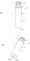
- FIG. 1A and 1B are perspective views of the container 1 of the first embodiment viewed from different directions.
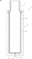
- 2A and 2B are perspective views of the container body 2 viewed from different directions. It is a cross-sectional view of the container body 2.
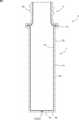
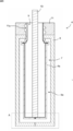
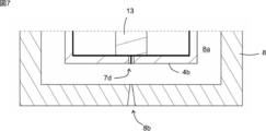
- 4A and 4B are perspective views of the blow-molded container 4 viewed from different directions. It is a cross-sectional view of the container 4. It is sectional drawing for demonstrating an integral molding process. It is an enlarged view of the area
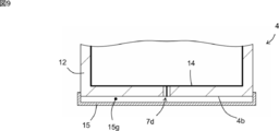
- FIG. 10A is an enlarged view corresponding to the vicinity of the bottom surface 4b of FIG.
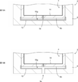
- FIG. 10A shows a state in which an outer jacket 5 is formed to cover the container 4 and the protective cover 15 in the state of FIG. 9, and FIG. 5 shows a state after the ventilation part 5c is formed.
- FIG. 4C is an enlarged view of the vicinity of the mouth portion 9 of FIG. 4A, showing a state in which the outside air introducing portion 4c is provided in the mouth portion 9 of the container 4 in the third embodiment.
- a storage container 1 As shown in FIG. 1, a storage container 1 according to the first embodiment of the present invention includes a container body 2 and a pump 3. As shown in FIG. 3, the container body 2 includes a blow-molded container 4 and an outer jacket 5 integrated with the blow-molded container 4. Each configuration will be described below.
- the blow-molded container 4 shown in FIGS. 4 to 5 can be formed by blow molding a parison.
- the blow molding may be direct blow molding or injection blow molding.
- direct blow molding a container is manufactured by sandwiching a molten parison extruded from an extruder with a pair of split molds and blowing air into the parison.
- the parison may have a tubular shape or a sheet shape.
- injection blow molding a test tube-shaped bottomed parison called a preform is formed by injection molding, and blow molding is performed using this parison to manufacture a container.
- the container 4 may have a single-layer structure, but preferably has a multi-layer structure. Since an injection-molded container having a multi-layered structure is not easy to manufacture, it is particularly significant to apply the present invention when the container 4 has a multi-layered structure.
- the parison When forming the container 4 having a multi-layered structure, the parison also has a multi-layered structure. A multi-layered parison (multi-layered parison) can be formed by coextrusion.
- the container 4 is a so-called laminated peeling container that has an outer shell 12 and an inner bag 14, and the inner bag 14 shrinks as the contents decrease.
- the inner bag 14 separates from the outer shell 12 as the contents decrease, the inner bag 14 separates from the outer shell 12 and contracts. In such a container, it is difficult for outside air to enter the inner bag 14, so that deterioration of the contents is suppressed.
- the outer shell 12 is made of, for example, low-density polyethylene, linear low-density polyethylene, high-density polyethylene, polypropylene, ethylene-propylene copolymer and a mixture thereof.
- the outer shell 12 may have a multilayer structure.
- the inner bag 14 is preferably composed of a plurality of layers.
- an EVOH layer made of an ethylene-vinyl alcohol copolymer (EVOH) resin is used for the layer in contact with the outer shell 12, and for the layer in contact with the contents, for example, low density polyethylene, linear low density polyethylene, high
- An inner surface layer made of polyolefin such as density polyethylene, polypropylene, ethylene-propylene copolymer and mixtures thereof can be used.
- An adhesive layer is preferably used between the EVOH layer and the inner surface layer.
- the container 4 has a bottomed tubular shape, and is provided with a storage portion 7 for storing the content and a mouth portion 9 for discharging the content from the storage portion 7.
- the accommodating portion 7 includes a body portion 7a, a bottom portion 7b, and a flange portion 7c.
- the flange portion 7c is provided on the upper end of the body portion 7a.
- the flange portion 7c is provided so as to project radially outward from the body portion 7a.
- the mouth 9 is provided with an engaging portion (male screw portion) 9d so that the pump 3 can be mounted.
- the container 4 when the container 4 is formed by direct blow molding, the container 4 has a cut-out portion 7d formed by crushing a parison with a pair of split molds.
- the cut-out portion 7d is provided on the bottom portion 7b of the container 4, and the opposite surfaces of the parison are welded to the cut-out portion 7d so that the bottom of the container 4 is closed.
- the biting portion 7d closes the bottoms of the outer shell 12 and the inner bag 14, but since the strength of the biting portion 7d is particularly weak in the outer shell 12, the outer shell 12 is impacted by applying an impact to the outer shell 12.
- the outside air introduction part 4c can be formed by opening the biting part 7d.
- the outside air can be introduced between the outer shell 12 and the inner bag 14 through the outside air introducing portion 4c.
- the outside air introducing portion 4c may be formed by punching the outer shell 12.
- the outside air introducing section 4c may be provided in the housing section 7 or the mouth section 9.
- the outer jacket 5 is an injection-molded body that is integrally molded so as to cover the outer peripheral surface 4a (preferably the outer peripheral surface 4a and the bottom surface 4b) of the container 4.
- the outer jacket 5 includes a tubular portion 5a and a bottom portion 5b.
- the cylindrical portion 5a and the bottom portion 5b cover the outer peripheral surface 4a and the bottom surface 4b, respectively.
- the outer jacket 5 is provided with a ventilation part 5c that connects the space outside the storage container 1 and the outside air introduction part 4c.
- the ventilation part 5c may be a through hole or a groove.
- the ventilation part 5c may be formed at the time of injection molding or may be formed by post-processing after injection molding.
- the outer jacket 5 covers at least the housing 7, and the mouth 9 may or may not be covered.
- the vent portion 5c becomes unnecessary when the outside air introducing portion 4c is provided in the mouth portion 9.
- the container body 2 can be manufactured by a method including an integral molding step of integrally molding the container 4 and the outer jacket 5. As shown in FIGS. 6 to 7, in the integral molding step, the mouth 9 is fixed to the fixing portion 11 having the opening 11a, and the outer peripheral surface 4a (preferably the outer peripheral surface 4a and the bottom surface 4b) of the container 4 is injection molded.
- the support rod 13 is inserted into the container 4 in a state where the support rod 13 is placed in the mold 8 and is pressed against the inner surface of the bottom surface 4b. This suppresses the displacement of the container 7 of the container 4 during injection molding.
- the outer space of the container 4 inside the cavity 8a of the mold 8 is filled with resin to form the mantle 5.
- the resin is filled from the gate 8b into the cavity 8a.
- the gate 8b is preferably arranged at a position facing the bottom surface 4b (preferably the cut-out portion 7d) of the container 4. This is because, in this case, the resin is likely to be uniformly filled all around the container 4.
- the resin for injection molding preferably has a fluidity necessary for injection molding at a temperature lower than the melting point of the resin forming the outer shell 12 of the container 4. It is preferable that the inner bag 14 of the container 4 is preliminarily peeled off before the integral molding step. This is because the preliminary peeling is easier before the outer jacket 5 is integrally molded with the container 4.
- a pin is arranged at a site corresponding to the ventilation part 5c, and when the container body 2 is taken out from the mold 8, the pin is pulled out from the outer jacket 5. Any method can be adopted.
- the pump 3 is configured to discharge the contents from the container 4.
- the pump 3 is preferably configured so as not to introduce outside air into the container 4.
- the pump 3 includes a main body portion 3a, a piston portion 3b, a nozzle 3c, and a tube 3d.
- the main body portion 3a includes a tubular portion 3a1, a cylinder portion 3a2, and an upper wall portion 3a3.
- An engagement portion (female screw portion) (not shown) that is engaged with the engagement portion (male screw portion) 9d is provided on the inner surface of the cylindrical portion 3a1.
- the cylinder portion 3a2 is inserted into the mouth portion 9.
- the outer diameter of the cylinder portion 3a2 substantially matches the inner diameter of the mouth portion 9.
- the cylinder portion 3a2 has a tubular shape, and the piston portion 3b is slidable in the cylinder portion 3a2.
- the internal space of the cylinder portion 3a2 communicates with the nozzle 3c and the tube 3d.
- a pump mechanism including an elastic member and a valve is built in the internal space of the cylinder portion 3a2.
- Second Embodiment A second embodiment of the present invention will be described with reference to FIGS. 9 to 10.
- the present embodiment is similar to the first embodiment, and the main difference is that the protective cover 15 is used. The difference will be mainly described below.
- a protective cover 15 is provided so as to cover the cut-and-cut portion 7d in order to suppress damage to the inner bag 14 due to heat.
- the protective cover 15 covers the entire bottom surface 4b, but the protective cover 15 may cover only a part of the bottom surface 4b including the cutout portion 7d.
- the protective cover 15 is not particularly limited in thickness and material as long as it can protect the inner bag 14 in the cut-out portion 7d, and is made of, for example, the same resin as the outer shell 12. In this case, the protective cover 15 is inconspicuous and has an excellent appearance. On the other hand, with emphasis on heat resistance, the outer shell 12 may be formed of a material having higher heat resistance.
- the protective cover 15 can be attached to the container 4 by a method such as fitting, welding or adhesion.
- a method such as fitting, welding or adhesion.
- FIG. 9 there is a step between the end of the protective cover 15 and the outer shell 12, but the protective cover 15 may be attached so that there is no step between the end of the protective cover 15 and the outer shell 12. In this case, the protective cover 15 is inconspicuous.
- a gap 15g is provided between the protective cover 15 and the container 4.
- the ventilation portion 5c can be formed in the outer jacket 5 by drilling using a drilling tool such as a drill.
- a drilling tool such as a drill.
- the gap 15g is provided between the protective cover 15 and the container 4, when forming the ventilation part 5c in the outer jacket 5, the drilling is stopped when the tip of the drilling tool reaches the gap 15g. It is possible to prevent the inner bag 14 from being damaged by the punching tool.
- the gap 15g can be omitted if unnecessary, and the protective cover 15 can be brought into close contact with the bottom surface 4b.
- the ventilation portion 5c is not necessary and the gap 15g is also unnecessary. ..
- FIGS. 11 to 12 The present embodiment is similar to the first embodiment, and the main difference is that a projecting portion 7e is provided in the cut-out portion 7d of the container 4. The difference will be mainly described below.
- the support rod 13 is pressed against the inner surface of the bottom surface 4b, but in this case, the pressing force of the support rod 13 causes the inner bag 14 to open at the bite portion 7d. There is a risk that it will end up. Therefore, in the present embodiment, in order to suppress the opening of the inner bag 14, as shown in FIG. 11, the protruding portion 7e is provided in the cut-out portion 7d of the container 4.
- the protruding portion 7e is formed by protruding the biting portion 7d from the bottom surface 4b. As a result, the welding area of the inner bag 14 at the cut-and-cut portion 7d increases, and the sealing strength of the inner bag 14 increases, so that the inner bag 14 is prevented from opening.
- the outer shell 12 is preferably sealed at the protrusion 7e as shown in FIG.
- the outer jacket 5 that covers the container 4 can be formed.
- the protrusion 7e can also prevent damage to the inner bag 14 due to heat of the resin injected from the gate 8b.
- the outside air introducing portion 4c is not provided in the cutting portion 7d, so it is preferable to form the outside air introducing portion 4c by providing a through hole in the outer shell 12. In this case, it is preferable that the outside air introducing portion 4c is provided at a portion where the container 4 is not covered with the outer jacket 5. In this case, it is not necessary to provide the outer cover 5 with the ventilation portion 5c.
- the outside air introducing portion 4c is preferably provided at the mouth portion 9 as shown in FIG. 12, and particularly preferably at a position covered by the tubular portion 3a1 of the pump 3 shown in FIG. In this case, when the pump 3 is mounted, the outside air introducing portion 4c is not visually recognized, which is excellent in appearance.
- the outside air introducing portion 4c can be vented to the outside through a ventilation path such as a gap between the piston portion 3b and the tubular portion 3a1 or a gap between the lower end of the tubular portion 3a1 and the container 4.
- the outside air introducing section 4c is preferably provided on the flat section 9a provided on the mouth section 9.
- the flat portion 9a may be provided at a position closer to the housing portion 7 than the engaging portion 9d, or may be provided so as to divide the engaging portion 9d. In the latter case, there is an advantage that it is not necessary to lengthen the mouth portion 9 in order to provide the flat portion 9a.
Landscapes
- Engineering & Computer Science (AREA)
- Ceramic Engineering (AREA)
- Mechanical Engineering (AREA)
- Containers Having Bodies Formed In One Piece (AREA)
- Packages (AREA)
Abstract
外観に優れた収容容器を提供する。 本発明によれば、ブロー成形容器の外周面を被覆するように外套が一体成形されている容器本体を備え、前記外套は、射出成形体である、収容容器が提供される。
Description
本発明は、内容物を収容可能な収容容器に関する。
従来、内容物の減少に伴って内袋が収縮することによって容器の内部に空気が入り込むことを抑制する積層剥離容器が知られている(例えば、特許文献1)。
特許文献1の積層剥離容器は、ブロー成形で形成した容器の外周面をシュリンクフィルムで覆って構成されているが、より高級感を醸し出す外観が求められる場合がある。
本発明はこのような事情に鑑みてなされたものであり、外観に優れた収容容器を提供するものである。
本発明によれば、ブロー成形容器の外周面を被覆するように外套が一体成形されている容器本体を備え、前記外套は、射出成形体である、収容容器が提供される。
ブロー成形は、多層構造の容器を製造しやすいという利点があるものの、ブロー成形で形成した容器(ブロー成形容器)の外観は、射出成形で形成した容器(射出成形容器)に比べて外観が劣る場合がある。本発明の収容容器は、ブロー成形容器の外周面に、射出成形体からなる外套が一体成形されているので、多層構造が形成しやすく、かつ外観に優れている。
以下、本発明の種々の実施形態を例示する。以下に示す実施形態は互いに組み合わせ可能である。
好ましくは、前記記載の収容容器であって、前記外套は、前記ブロー成形容器の外周面及び底面を被覆するように一体成形されている、収容容器である。
好ましくは、前記記載の収容容器であって、前記ブロー成形容器は、外殻と内袋とを有し且つ内容物の減少に伴って前記内袋が収縮するように構成される、収容容器である。
好ましくは、前記記載の収容容器であって、前記外套は、前記収容容器の外側の空間と前記外気導入部を連通する通気部を備える、収容容器である。
好ましくは、前記記載の収容容器であって、前記外気導入部は、前記外殻の喰切部に設けられる、収容容器である。
好ましくは、前記記載の収容容器であって、前記ブロー成形容器の外殻は、前記ブロー成形容器が前記外套で被覆されていない部位に外気導入部を備える、収容容器である。
好ましくは、前記記載の収容容器であって、前記外気導入部は、前記ブロー成形容器の口部に装着されるポンプの筒部で被覆される部位に設けられる、収容容器である。
好ましくは、前記記載の収容容器であって、前記ブロー成形容器の喰切部を覆う保護カバーを備える、収容容器である。
好ましくは、前記記載の収容容器であって、前記ブロー成形容器の喰切部に、前記ブロー成形容器の底面から突出する突出部が設けられている、収容容器である。
好ましくは、ブロー成形容器と外套を一体成形する一体成形工程を備える、収容容器の製造方法であって、前記一体成形工程では、前記ブロー成形容器の外周面を金型内に配置した状態で前記金型のキャビティ内の前記ブロー成形容器の外側の空間に樹脂を充填して前記外套を形成する、方法である。
好ましくは、前記記載の方法であって、前記一体成形工程の際に前記ブロー成形容器内を加圧する、方法である。
好ましくは、前記記載の方法であって、前記一体成形工程では、前記ブロー成形容器は、前記ブロー成形容器の喰切部を覆う保護カバーを装着した状態で前記金型内に配置される、方法である。
好ましくは、前記記載の方法であって、前記一体成形工程では、前記ブロー成形容器内に挿入された支持棒で、前記ブロー成形容器の底面の内面を押圧した状態で前記樹脂の充填が行われる、方法である。
好ましくは、前記記載の方法であって、前記ブロー成形容器の喰切部に、前記ブロー成形容器の底面から突出する突出部が設けられている、方法である。
好ましくは、前記記載の収容容器であって、前記外套は、前記ブロー成形容器の外周面及び底面を被覆するように一体成形されている、収容容器である。
好ましくは、前記記載の収容容器であって、前記ブロー成形容器は、外殻と内袋とを有し且つ内容物の減少に伴って前記内袋が収縮するように構成される、収容容器である。
好ましくは、前記記載の収容容器であって、前記外套は、前記収容容器の外側の空間と前記外気導入部を連通する通気部を備える、収容容器である。
好ましくは、前記記載の収容容器であって、前記外気導入部は、前記外殻の喰切部に設けられる、収容容器である。
好ましくは、前記記載の収容容器であって、前記ブロー成形容器の外殻は、前記ブロー成形容器が前記外套で被覆されていない部位に外気導入部を備える、収容容器である。
好ましくは、前記記載の収容容器であって、前記外気導入部は、前記ブロー成形容器の口部に装着されるポンプの筒部で被覆される部位に設けられる、収容容器である。
好ましくは、前記記載の収容容器であって、前記ブロー成形容器の喰切部を覆う保護カバーを備える、収容容器である。
好ましくは、前記記載の収容容器であって、前記ブロー成形容器の喰切部に、前記ブロー成形容器の底面から突出する突出部が設けられている、収容容器である。
好ましくは、ブロー成形容器と外套を一体成形する一体成形工程を備える、収容容器の製造方法であって、前記一体成形工程では、前記ブロー成形容器の外周面を金型内に配置した状態で前記金型のキャビティ内の前記ブロー成形容器の外側の空間に樹脂を充填して前記外套を形成する、方法である。
好ましくは、前記記載の方法であって、前記一体成形工程の際に前記ブロー成形容器内を加圧する、方法である。
好ましくは、前記記載の方法であって、前記一体成形工程では、前記ブロー成形容器は、前記ブロー成形容器の喰切部を覆う保護カバーを装着した状態で前記金型内に配置される、方法である。
好ましくは、前記記載の方法であって、前記一体成形工程では、前記ブロー成形容器内に挿入された支持棒で、前記ブロー成形容器の底面の内面を押圧した状態で前記樹脂の充填が行われる、方法である。
好ましくは、前記記載の方法であって、前記ブロー成形容器の喰切部に、前記ブロー成形容器の底面から突出する突出部が設けられている、方法である。
以下、本発明の実施形態について説明する。以下に示す実施形態中で示した各種特徴事項は、互いに組み合わせ可能である。また、各特徴について独立して発明が成立する。
1.第1実施形態
図1に示すように、本発明の第1実施形態の収容容器1は、容器本体2と、ポンプ3を備える。図3に示すように、容器本体2は、ブロー成形容器4と、これと一体化された外套5を備える。以下、各構成について説明する。
図1に示すように、本発明の第1実施形態の収容容器1は、容器本体2と、ポンプ3を備える。図3に示すように、容器本体2は、ブロー成形容器4と、これと一体化された外套5を備える。以下、各構成について説明する。
<ブロー成形容器4>
図4~図5に示すブロー成形容器4は、パリソンのブロー成形によって形成することができる。ブロー成形は、ダイレクトブロー成形であってもよく、インジェクションブロー成形であってもよい。ダイレクトブロー成形では、押出機から押し出された溶融状態のパリソンを一対の分割金型で挟んでパリソン内部にエアーを吹き込むことによって容器を製造する。パリソンは、筒状であっても、シート状であってもよい。インジェクションブロー成形では、プリフォームと呼ばれる試験管状の有底パリソンを射出成形によって形成し、このパリソンを用いてブロー成形を行うことによって容器を製造する。
図4~図5に示すブロー成形容器4は、パリソンのブロー成形によって形成することができる。ブロー成形は、ダイレクトブロー成形であってもよく、インジェクションブロー成形であってもよい。ダイレクトブロー成形では、押出機から押し出された溶融状態のパリソンを一対の分割金型で挟んでパリソン内部にエアーを吹き込むことによって容器を製造する。パリソンは、筒状であっても、シート状であってもよい。インジェクションブロー成形では、プリフォームと呼ばれる試験管状の有底パリソンを射出成形によって形成し、このパリソンを用いてブロー成形を行うことによって容器を製造する。
容器4は、単層構成であってもよいが、多層構成であることが好ましい。多層構成の射出成形容器は製造が容易ではないので、容器4が多層構成である場合に本発明を適用する意義が特に大きい。多層構成の容器4を形成する場合、パリソンも多層構成とする。多層構成のパリソン(多層パリソン)は、共押出成形によって形成可能である。
本実施形態では、図5に示すように、容器4は、外殻12と内袋14とを有し且つ内容物の減少に伴って内袋14が収縮する、いわゆる積層剥離容器である。内容物の減少に伴って内袋14が外殻12から離れることによって、内袋14が外殻12から離れて収縮する。このような容器では、内袋14内に外気が侵入しにくいので、内容物の劣化が抑制される。
外殻12は、例えば、低密度ポリエチレン、直鎖状低密度ポリエチレン、高密度ポリエチレン、ポリプロピレン、エチレン-プロピレン共重合体及びその混合物などで構成される。外殻12は、複数層構成であってもよい。内袋14は、複数の層から構成することが好ましい。例えば、外殻12と接触する層にエチレン-ビニルアルコール共重合体(EVOH)樹脂からなるEVOH層を用い、内容物に接触する層に、例えば、低密度ポリエチレン、直鎖状低密度ポリエチレン、高密度ポリエチレン、ポリプロピレン、エチレン-プロピレン共重合体及びその混合物などのポリオレフィンからなる内面層を用いることができる。そして、上記EVOH層と内面層との間には、接着層を用いることが好ましい。
容器4は、有底筒状であり、内容物を収容する収容部7と、収容部7から内容物を吐出する口部9を備える。収容部7は、胴部7aと、底部7bと、フランジ部7cを備える。フランジ部7cは、胴部7aの上端に設けられている。フランジ部7cは、胴部7aから径方向外側に突出するように設けられている。口部9には係合部(雄ねじ部)9dが設けられており、ポンプ3を装着可能になっている。
ところで、ダイレクトブロー成形によって容器4を形成する場合、容器4には、一対の分割金型でパリソンを押し潰して形成した喰切部7dが存在している。喰切部7dは容器4の底部7bに設けられており、喰切部7dにパリソンの対向する面同士が溶着されることよって容器4の底が閉じられている。喰切部7dは、外殻12と内袋14のそれぞれの底部を閉塞させているが、外殻12では喰切部7dの強度が特に弱いので、外殻12に衝撃を加えることによって外殻12において喰切部7dを開いて外気導入部4cを形成することができる。外気導入部4cを通じて外殻12と内袋14の間に外気を導入することができる。外気導入部4cは、外殻12を穿孔することによって形成してもよい。外気導入部4cは、収容部7に設けてもよく、口部9に設けてもよい。
<外套5>
図2~図3に示すように、外套5は、容器4の外周面4a(好ましくは外周面4a及び底面4b)を被覆するように一体成形されており、射出成形体である。外套5は、筒部5aと、底部5bを備える。筒部5a及び底部5bがそれぞれ、外周面4a及び底面4bを被覆する。
図2~図3に示すように、外套5は、容器4の外周面4a(好ましくは外周面4a及び底面4b)を被覆するように一体成形されており、射出成形体である。外套5は、筒部5aと、底部5bを備える。筒部5a及び底部5bがそれぞれ、外周面4a及び底面4bを被覆する。
容器4の外気導入部4cが外套5で被覆されてしまうと、外気導入部4cを通じて外気が導入されなくなる。このため、外套5には、収容容器1の外側の空間と外気導入部4cを連通する通気部5cを備える。通気部5cは貫通孔であってもよく、溝であってもよい。通気部5cは、射出成形の際に形成してもよく、射出成形後の後加工によって形成してもよい。
外套5は、収容部7を少なくとも被覆し、口部9は被覆してもしていなくてもよい。外套5が口部9を被覆しない場合、口部9に外気導入部4cを設けると、通気部5cが不要になる。
容器本体2は、容器4と外套5を一体成形する一体成形工程を備える方法によって製造可能である。図6~図7に示すように、一体成形工程では、開口部11aを有する固定部11に口部9を固定し、容器4の外周面4a(好ましくは外周面4a及び底面4b)を射出成形用の金型8内に配置した状態で、支持棒13を容器4内に挿入して、支持棒13を底面4bの内面に押し付ける。これによって、射出成形の際に容器4の収容部7が変位することが抑制される。
この状態で、金型8のキャビティ8a内の容器4の外側の空間に樹脂を充填して外套5を形成する。この際に、樹脂圧によって容器4が変形しないように、容器4の内部を加圧することが好ましい。加圧は、水やエアーを吹き込むことによって行うことができる。樹脂は、ゲート8bからキャビティ8a内に充填される。ゲート8bは、容器4の底面4b(好ましくは喰切部7d)に対向する位置に配置することが好ましい。この場合、容器4の周囲の全体に樹脂が均一に充填されやすいからである。
射出成形用の樹脂は、容器4の外殻12を構成する樹脂の融点より低い温度で、射出成形に必要な流動性を有するものが好ましい。容器4は、一体成形工程の前に、内袋14を予備剥離しておくことが好ましい。容器4に外套5を一体成形する前の方が予備剥離が容易であるからである。
射出成形の際に通気部5cを形成する場合には、例えば、通気部5cに相当する部位にピンを配置しておき、金型8から容器本体2を取り出す際に、外套5からピンを抜く方法が採用可能である。
<ポンプ3>
ポンプ3は、内容物を容器4から排出させるように構成されている。容器4が積層剥離容器である場合には、ポンプ3は、容器4内へ外気を導入させないように構成されていることが好ましい。
ポンプ3は、内容物を容器4から排出させるように構成されている。容器4が積層剥離容器である場合には、ポンプ3は、容器4内へ外気を導入させないように構成されていることが好ましい。
図8に示すように、ポンプ3は、本体部3aと、ピストン部3bと、ノズル3cと、チューブ3dを備える。本体部3aは、筒部3a1と、シリンダ部3a2と、上壁部3a3を備える。筒部3a1の内面には、係合部(雄ねじ部)9dに係合される係合部(雌ねじ部)(不図示)が設けられている。シリンダ部3a2は、口部9内に挿入される。シリンダ部3a2の外径は、口部9の内径とほぼ一致している。シリンダ部3a2は、筒状であり、ピストン部3bがシリンダ部3a2内で摺動可能になっている。シリンダ部3a2の内部空間は、ノズル3c及びチューブ3dに連通されている。シリンダ部3a2の内部空間には、弾性部材と弁で構成されるポンプ機構が内蔵されている。ピストン部3bを摺動させてポンプ機構を作動させることによって、チューブ3dを通じて吸い上げた内容物をノズル3cから排出することが可能になっている。
2.第2実施形態
図9~図10を用いて、本発明の第2実施形態について説明する。本実施形態は、第1実施形態に類似しており、保護カバー15を用いる点が主な相違点である。以下、相違点を中心に説明する。
図9~図10を用いて、本発明の第2実施形態について説明する。本実施形態は、第1実施形態に類似しており、保護カバー15を用いる点が主な相違点である。以下、相違点を中心に説明する。
図7に示すようにゲート8bが容器4の喰切部7dに対向する位置に配置している場合、ゲート8bから注入される高温の樹脂が、喰切部7dにおいて内袋14に接触して内袋14が熱によって損傷されやすい。そこで、本実施形態では、図9に示すように、熱による内袋14の損傷を抑制すべく、喰切部7dを覆うように保護カバー15を設けている。図9では、保護カバー15は、底面4bの全体を覆っているが、保護カバー15は、喰切部7dを含む、底面4bの一部のみを覆ってもよい。
保護カバー15は、喰切部7dにおいて内袋14を保護可能であれば、その厚さや材料は特に限定されず、例えば、外殻12と同様の樹脂で構成される。この場合、保護カバー15が目立ちにくく、外観に優れている。一方、耐熱性を重視して、外殻12よりも耐熱性に優れた材料で形成してもよい。
保護カバー15は、嵌合、溶着、接着などの方法によって、容器4に装着することができる。図9では、保護カバー15の端部と外殻12の間に段差があるが、保護カバー15の端部と外殻12の間に段差がないように保護カバー15を装着してもよい。この場合、保護カバー15が目立ちにくい。保護カバー15と容器4の間には隙間15gが設けられている。
容器4に保護カバー15を装着した状態のものを、図6に示す金型8内に配置して、第1実施形態と同様に一体成形工程を行うことによって、図10Aに示すように、容器4を覆う外套5を形成することができる。次に、図10Bに示すように、ドリルなどの穿孔工具を用いて穿孔することによって外套5に通気部5cを形成することができる。本実施形態では、保護カバー15と容器4の間に隙間15gが設けられているので、外套5に通気部5cを形成する際に、穿孔工具の先端が隙間15gに到達した時点で穿孔を停止させることができ、穿孔工具で内袋14を損傷させることが抑制される。
なお、隙間15gは不要な場合には省略可能であり、保護カバー15は底面4bに密着させることができる。例えば、図12に示すように、容器4が外套5で覆われていない部位(例:口部9)に外気導入部4cを設ける場合、通気部5cは不要であり、隙間15gも不要である。
3.第3実施形態
図11~図12を用いて、本発明の第3実施形態について説明する。本実施形態は、第1実施形態に類似しており、容器4の喰切部7dに突出部7eが設けられている点が主な相違点である。以下、相違点を中心に説明する。
図11~図12を用いて、本発明の第3実施形態について説明する。本実施形態は、第1実施形態に類似しており、容器4の喰切部7dに突出部7eが設けられている点が主な相違点である。以下、相違点を中心に説明する。
第1実施形態で述べたように、一体成形工程では、支持棒13を底面4bの内面に押し付けているが、この場合、支持棒13による押圧力によって、喰切部7dにおいて内袋14が開いてしまう虞がある。そこで、本実施形態では、内袋14の開きを抑制すべく、図11に示すように、容器4の喰切部7dに突出部7eを設けている。
突出部7eは、喰切部7dを底面4bから突出させることによって形成している。これによって、喰切部7dでの内袋14の溶着面積が増大して、内袋14のシール強度が高められるので、内袋14が開くことが抑制される。突出部7eでは、図11に示すように、外殻12がシールされていることが好ましい。
このような形状の容器4を図6に示す金型8内に配置して、第1実施形態と同様に一体成形工程を行うことによって、容器4を覆う外套5を形成することができる。突出部7eは、ゲート8bから注入される樹脂の熱による内袋14の損傷も抑制することができる。
外殻12がシールされている場合、喰切部7dに外気導入部4cが設けられないので、外殻12に貫通孔を設けて外気導入部4cを構成することが好ましい。この場合、外気導入部4cは、容器4が外套5で覆われていない部位に設けることが好ましい。この場合、外套5に通気部5cを設けることが不要になるからである。
外気導入部4cは、図12に示すように、口部9に設けることが好ましく、図8に示すポンプ3の筒部3a1で覆われる位置に設けることが特に好ましい。この場合、ポンプ3を装着した状態では、外気導入部4cが視認されないので、美観に優れている。外気導入部4cは、ピストン部3bと筒部3a1の間の隙間や、筒部3a1の下端と容器4の間の隙間等の通気路を通じて、外部に通気可能になっている。
また、外気導入部4cは、口部9に設けた平坦部9aに設けることが好ましい。この場合、ドリルなどの穿孔工具を用いて外気導入部4cを形成しやすいからである。平坦部9aは、係合部9dより収容部7に近い位置に設けてもよく、係合部9dを分断するように設けてもよい。後者の場合、平坦部9aを設けるために口部9を長くする必要がないという利点がある。
1:収容容器、2:容器本体、3:ポンプ、3a:本体部、3a1:筒部、3a2:シリンダ部、3a3:上壁部、3b:ピストン部、3c:ノズル、3d:チューブ、4:ブロー成形容器、4a:外周面、4b:底面、4c:外気導入部、5:外套、5a:筒部、5b:底部、5c:通気部、7:収容部、7a:胴部、7b:底部、7c:フランジ部、7d:喰切部、7e:突出部、8:金型、8a:キャビティ、8b:ゲート、9:口部、9d:係合部、11:固定部、11a:開口部、12:外殻、13:支持棒、14:内袋、15:保護カバー、15g:隙間
Claims (14)
- ブロー成形容器の外周面を被覆するように外套が一体成形されている容器本体を備え、
前記外套は、射出成形体である、収容容器。 - 請求項1に記載の収容容器であって、
前記外套は、前記ブロー成形容器の外周面及び底面を被覆するように一体成形されている、収容容器。 - 請求項1又は請求項2に記載の収容容器であって、
前記ブロー成形容器は、外殻と内袋とを有し且つ内容物の減少に伴って前記内袋が収縮するように構成される、収容容器。 - 請求項3に記載の収容容器であって、
前記外套は、前記収容容器の外側の空間と前記外気導入部を連通する通気部を備える、収容容器。 - 請求項3又は請求項4に記載の収容容器であって、
前記外気導入部は、前記外殻の喰切部に設けられる、収容容器。 - 請求項3に記載の収容容器であって、
前記ブロー成形容器の外殻は、前記ブロー成形容器が前記外套で被覆されていない部位に外気導入部を備える、収容容器。 - 請求項3又は請求項4に記載の収容容器であって、
前記外気導入部は、前記ブロー成形容器の口部に装着されるポンプの筒部で被覆される部位に設けられる、収容容器。 - 請求項1~請求項7の何れか1つに記載の収容容器であって、
前記ブロー成形容器の喰切部を覆う保護カバーを備える、収容容器。 - 請求項1~請求項8の何れか1つに記載の収容容器であって、
前記ブロー成形容器の喰切部に、前記ブロー成形容器の底面から突出する突出部が設けられている、収容容器。 - ブロー成形容器と外套を一体成形する一体成形工程を備える、収容容器の製造方法であって、
前記一体成形工程では、前記ブロー成形容器の外周面を金型内に配置した状態で前記金型のキャビティ内の前記ブロー成形容器の外側の空間に樹脂を充填して前記外套を形成する、方法。 - 請求項10に記載の方法であって、
前記一体成形工程の際に前記ブロー成形容器内を加圧する、方法。 - 請求項10又は請求項11に記載の方法であって、
前記一体成形工程では、前記ブロー成形容器は、前記ブロー成形容器の喰切部を覆う保護カバーを装着した状態で前記金型内に配置される、方法。 - 請求項10~請求項12の何れか1つに記載の方法であって、
前記一体成形工程では、前記ブロー成形容器内に挿入された支持棒で、前記ブロー成形容器の底面の内面を押圧した状態で前記樹脂の充填が行われる、方法。 - 請求項10~請求項13の何れか1つに記載の方法であって、
前記ブロー成形容器の喰切部に、前記ブロー成形容器の底面から突出する突出部が設けられている、方法。
Priority Applications (1)
| Application Number | Priority Date | Filing Date | Title |
|---|---|---|---|
| CN202080006856.3A CN113165767B (zh) | 2019-01-28 | 2020-01-22 | 收容容器及其制造方法 |
Applications Claiming Priority (4)
| Application Number | Priority Date | Filing Date | Title |
|---|---|---|---|
| JP2019-011851 | 2019-01-28 | ||
| JP2019011851 | 2019-01-28 | ||
| JP2019-119989 | 2019-06-27 | ||
| JP2019119989A JP7385102B2 (ja) | 2019-01-28 | 2019-06-27 | 収容容器及びその製造方法 |
Publications (1)
| Publication Number | Publication Date |
|---|---|
| WO2020158549A1 true WO2020158549A1 (ja) | 2020-08-06 |
Family
ID=71840965
Family Applications (1)
| Application Number | Title | Priority Date | Filing Date |
|---|---|---|---|
| PCT/JP2020/002178 Ceased WO2020158549A1 (ja) | 2019-01-28 | 2020-01-22 | 収容容器及びその製造方法 |
Country Status (1)
| Country | Link |
|---|---|
| WO (1) | WO2020158549A1 (ja) |
Citations (10)
| Publication number | Priority date | Publication date | Assignee | Title |
|---|---|---|---|---|
| JPH05213373A (ja) * | 1991-09-18 | 1993-08-24 | Kamaya Kagaku Kogyo Co Ltd | 容器およびその製造方法 |
| JPH1029634A (ja) * | 1996-07-15 | 1998-02-03 | Toyo Seikan Kaisha Ltd | 積層剥離ボトル及びその製造方法 |
| JP2004059077A (ja) * | 2002-07-30 | 2004-02-26 | Yoshino Kogyosho Co Ltd | ブロー成形容器とその成形方法 |
| JP2004231270A (ja) * | 2003-01-31 | 2004-08-19 | Yoshino Kogyosho Co Ltd | 合成樹脂製容器 |
| KR20100027314A (ko) * | 2008-09-02 | 2010-03-11 | 이승훈 | 적층용기 제조방법 및 이를 이용한 적층용기 |
| JP2010222057A (ja) * | 2009-02-27 | 2010-10-07 | Yoshino Kogyosho Co Ltd | 合成樹脂製ボトルとその成形方法 |
| JP2012101486A (ja) * | 2010-11-11 | 2012-05-31 | Yoshida Industry Co Ltd | オーバーモールド容器の製造方法、オーバーモールド容器の製造装置、ブロー成形装置、オーバーモールド容器 |
| JP2015199512A (ja) * | 2014-04-07 | 2015-11-12 | 株式会社クレハ | 喰い切り支持部を備え、カーボンラベリングされた表面層を備える合成樹脂製ブロー成形多層容器 |
| JP2017105497A (ja) * | 2015-12-09 | 2017-06-15 | 株式会社平和化学工業所 | 二重容器及びその製造方法 |
| WO2018168922A1 (ja) * | 2017-03-15 | 2018-09-20 | キョーラク株式会社 | 積層剥離容器 |
-
2020
- 2020-01-22 WO PCT/JP2020/002178 patent/WO2020158549A1/ja not_active Ceased
Patent Citations (10)
| Publication number | Priority date | Publication date | Assignee | Title |
|---|---|---|---|---|
| JPH05213373A (ja) * | 1991-09-18 | 1993-08-24 | Kamaya Kagaku Kogyo Co Ltd | 容器およびその製造方法 |
| JPH1029634A (ja) * | 1996-07-15 | 1998-02-03 | Toyo Seikan Kaisha Ltd | 積層剥離ボトル及びその製造方法 |
| JP2004059077A (ja) * | 2002-07-30 | 2004-02-26 | Yoshino Kogyosho Co Ltd | ブロー成形容器とその成形方法 |
| JP2004231270A (ja) * | 2003-01-31 | 2004-08-19 | Yoshino Kogyosho Co Ltd | 合成樹脂製容器 |
| KR20100027314A (ko) * | 2008-09-02 | 2010-03-11 | 이승훈 | 적층용기 제조방법 및 이를 이용한 적층용기 |
| JP2010222057A (ja) * | 2009-02-27 | 2010-10-07 | Yoshino Kogyosho Co Ltd | 合成樹脂製ボトルとその成形方法 |
| JP2012101486A (ja) * | 2010-11-11 | 2012-05-31 | Yoshida Industry Co Ltd | オーバーモールド容器の製造方法、オーバーモールド容器の製造装置、ブロー成形装置、オーバーモールド容器 |
| JP2015199512A (ja) * | 2014-04-07 | 2015-11-12 | 株式会社クレハ | 喰い切り支持部を備え、カーボンラベリングされた表面層を備える合成樹脂製ブロー成形多層容器 |
| JP2017105497A (ja) * | 2015-12-09 | 2017-06-15 | 株式会社平和化学工業所 | 二重容器及びその製造方法 |
| WO2018168922A1 (ja) * | 2017-03-15 | 2018-09-20 | キョーラク株式会社 | 積層剥離容器 |
Similar Documents
| Publication | Publication Date | Title |
|---|---|---|
| JP7108206B2 (ja) | 積層剥離容器 | |
| JP6959498B2 (ja) | 積層剥離容器 | |
| CN102328439B (zh) | 用于成形压力容器的容器内衬的方法和装置 | |
| JP6923788B2 (ja) | 積層剥離容器 | |
| JP6421458B2 (ja) | 積層剥離容器 | |
| WO2010073650A1 (ja) | プラスチック容器及びその製造方法 | |
| JP6780911B2 (ja) | 積層剥離容器 | |
| CN114502475B (zh) | 收容容器及其制造方法 | |
| JP2021127164A (ja) | 二重容器 | |
| JP2017081584A (ja) | 二重容器及びその製造方法 | |
| JP7004898B2 (ja) | 積層剥離容器及び積層剥離容器のエアリーク検査方法 | |
| JP7385102B2 (ja) | 収容容器及びその製造方法 | |
| JP7545019B2 (ja) | 収容容器及びその製造方法 | |
| JP2017145020A (ja) | 二重容器及びその製造方法 | |
| WO2020158549A1 (ja) | 収容容器及びその製造方法 | |
| JP7364891B2 (ja) | 容器及び容器口部のシール方法 | |
| JP7663813B2 (ja) | 二重容器及びその処理方法 | |
| JP6562594B2 (ja) | 積層剥離容器 | |
| JP7200400B2 (ja) | ブロー成形機及びこれを用いた圧力容器のための樹脂ライナーの製造方法 | |
| JP5776331B2 (ja) | チューブ容器の口部製造装置 | |
| JP5776331B6 (ja) | チューブ容器の口部製造装置 | |
| JP2012245696A6 (ja) | チューブ容器の口部製造装置 |
Legal Events
| Date | Code | Title | Description |
|---|---|---|---|
| 121 | Ep: the epo has been informed by wipo that ep was designated in this application |
Ref document number: 20747832 Country of ref document: EP Kind code of ref document: A1 |
|
| NENP | Non-entry into the national phase |
Ref country code: DE |
|
| 122 | Ep: pct application non-entry in european phase |
Ref document number: 20747832 Country of ref document: EP Kind code of ref document: A1 |