WO2020158538A1 - 空気調和装置システム - Google Patents
空気調和装置システム Download PDFInfo
- Publication number
- WO2020158538A1 WO2020158538A1 PCT/JP2020/002110 JP2020002110W WO2020158538A1 WO 2020158538 A1 WO2020158538 A1 WO 2020158538A1 JP 2020002110 W JP2020002110 W JP 2020002110W WO 2020158538 A1 WO2020158538 A1 WO 2020158538A1
- Authority
- WO
- WIPO (PCT)
- Prior art keywords
- time
- air conditioner
- wake
- temperature
- air conditioning
- Prior art date
- Legal status (The legal status is an assumption and is not a legal conclusion. Google has not performed a legal analysis and makes no representation as to the accuracy of the status listed.)
- Ceased
Links
Images

Classifications
-
- F—MECHANICAL ENGINEERING; LIGHTING; HEATING; WEAPONS; BLASTING
- F24—HEATING; RANGES; VENTILATING
- F24F—AIR-CONDITIONING; AIR-HUMIDIFICATION; VENTILATION; USE OF AIR CURRENTS FOR SCREENING
- F24F11/00—Control or safety arrangements
- F24F11/30—Control or safety arrangements for purposes related to the operation of the system, e.g. for safety or monitoring
- F24F11/48—Control or safety arrangements for purposes related to the operation of the system, e.g. for safety or monitoring prior to normal operation, e.g. pre-heating or pre-cooling
-
- F—MECHANICAL ENGINEERING; LIGHTING; HEATING; WEAPONS; BLASTING
- F24—HEATING; RANGES; VENTILATING
- F24F—AIR-CONDITIONING; AIR-HUMIDIFICATION; VENTILATION; USE OF AIR CURRENTS FOR SCREENING
- F24F11/00—Control or safety arrangements
- F24F11/50—Control or safety arrangements characterised by user interfaces or communication
- F24F11/56—Remote control
- F24F11/58—Remote control using Internet communication
-
- F—MECHANICAL ENGINEERING; LIGHTING; HEATING; WEAPONS; BLASTING
- F24—HEATING; RANGES; VENTILATING
- F24F—AIR-CONDITIONING; AIR-HUMIDIFICATION; VENTILATION; USE OF AIR CURRENTS FOR SCREENING
- F24F11/00—Control or safety arrangements
- F24F11/50—Control or safety arrangements characterised by user interfaces or communication
- F24F11/61—Control or safety arrangements characterised by user interfaces or communication using timers
-
- F—MECHANICAL ENGINEERING; LIGHTING; HEATING; WEAPONS; BLASTING
- F24—HEATING; RANGES; VENTILATING
- F24F—AIR-CONDITIONING; AIR-HUMIDIFICATION; VENTILATION; USE OF AIR CURRENTS FOR SCREENING
- F24F11/00—Control or safety arrangements
- F24F11/70—Control systems characterised by their outputs; Constructional details thereof
- F24F11/80—Control systems characterised by their outputs; Constructional details thereof for controlling the temperature of the supplied air
- F24F11/86—Control systems characterised by their outputs; Constructional details thereof for controlling the temperature of the supplied air by controlling compressors within refrigeration or heat pump circuits
-
- G—PHYSICS
- G04—HOROLOGY
- G04G—ELECTRONIC TIME-PIECES
- G04G15/00—Time-pieces comprising means to be operated at preselected times or after preselected time intervals
Definitions
- the present invention relates to an air conditioner system.
- This application claims priority based on Japanese Patent Application No. 2019-11902 filed in Japan on January 28, 2019, the content of which is incorporated herein by reference.
- Patent Document 1 discloses an air conditioner in which the heating and cooling operation is started at the alarm time of the alarm clock.
- One form of this invention aims at providing the air conditioning apparatus system which adjusts to a comfortable temperature, when a user gets up.
- the air conditioner system activates an alarm time acquisition unit that acquires an alarm time and an air conditioner installed in the first room based on the alarm time.
- a start time acquisition unit that acquires a start time
- an operation control unit that controls the air conditioner based on the wake-up time and the start time are included.
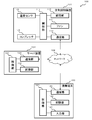
- FIG. 1 It is a figure which shows an example of the air conditioning apparatus system which concerns on 1st Embodiment. It is a figure which shows an example of the specific structure of the air conditioning apparatus shown in FIG. It is a figure which shows an example of a functional structure of the control part of the portable terminal shown in FIG. It is a figure which shows an example of a functional structure of the control part of the server apparatus shown in FIG. It is a figure which shows an example of driving time information. It is a figure which shows an example of the operating condition in an air conditioning apparatus with respect to each operation mode of an alarm mode. It is a figure which shows an example of the flow of the air conditioning apparatus which concerns on 1st Embodiment.
- FIG. 1 is a diagram showing an example of an air conditioner system according to the present embodiment.
- the air conditioning apparatus system 100 includes an air conditioning apparatus 101, a network 102, a mobile terminal 103, and a server device (information processing device) 104.
- the air conditioner 101, the mobile terminal 103, and the server device 104 are connected via a network 102.
- the air conditioner 101 is, for example, an air conditioner or the like, is installed in the user's bedroom, and air-conditions the bedroom.
- the network 102 corresponds to, for example, the Internet or Bluetooth (registered trademark).
- the mobile terminal 103 is, for example, a device such as a smartphone or a remote controller, and is a device for a user to input an alarm time or the like set in the air conditioning apparatus 101.
- the mobile terminal 103 in the present embodiment may be, for example, an alarm clock or the like connected to the network 102 as long as it can transmit an alarm time.
- the air conditioning apparatus 101 and the mobile terminal 103 are identified by, for example, an ID, and the mobile terminal 103 is registered in the air conditioning apparatus 101.
- the air conditioning apparatus 101 includes, for example, a control unit 111, a storage unit 112, a communication unit 113, a fan 114, a compressor 115, a temperature sensor 116, and the like.
- the control unit 111 is, for example, a CPU, an MPU, or the like, and executes various types of information processing according to a program stored in the storage unit 112.
- the storage unit 112 is, for example, a flash memory, a RAM, or the like, and holds a program executed by the control unit 111 and various data.
- the storage unit 112 also operates as a work memory for the control unit 111.
- the communication unit 113 is an interface or the like, and communicates with the mobile terminal 103 and the server device 104 via the network 102.
- the air conditioner 101 includes, for example, a louver and an ion generator in addition to the above-mentioned units, and is connected to and controlled by the control unit 111.
- the mobile terminal 103 includes, for example, a control unit 121, a storage unit 122, a communication unit 123, and an input unit 124, like the air conditioning apparatus 101.
- the main configurations of the control unit 121, the storage unit 122, and the communication unit 123 are the same as those of the air conditioning apparatus 101, and thus the description thereof will be omitted.
- the user inputs the alarm clock time, the set temperature, the operation mode, and the like from the input unit 124.
- the server device 104 includes, for example, a control unit 131, a storage unit 132, and a communication unit 133.
- the main configurations of the control unit 131, the storage unit 132, and the communication unit 133 are the same as those of the air conditioner 101, and thus the description thereof will be omitted.
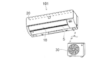
- FIG. 2 is a diagram showing a specific example of the air conditioner 101.
- the air conditioning apparatus 101 has, for example, an indoor unit 20 and an outdoor unit 30.
- the indoor unit 20 has a heat exchanger (not shown), a fan 114 (see FIG. 1), and a louver 18 provided at the outlet 5 inside. By operating the fan 114, the air is blown from the outlet 5, and the direction of the air is controlled by the louver 18.
- the outdoor unit 30 has a compressor 115 (see FIG. 1) inside.
- the heat exchanger and the compressor 115 are connected.
- the compressor 115 When the compressor 115 is driven, the refrigeration cycle is operated, and the heat exchanger performs heat exchange of the air (wind) blown out from the blowout port 5.
- cool air or warm air is blown out from the outlet 5, and the air conditioner 101 performs air conditioning of the installed space.
- the configuration of the air conditioning apparatus 101 is an example, and the present invention is not limited to this.
- the air conditioner 101 may be, for example, an attached remote controller and configured to set the temperature, air volume, and operation mode.
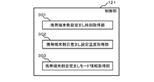
- FIG. 3 is a diagram showing an example of a functional configuration of the control unit 121 in the mobile terminal 103 shown in FIG.
- the control unit 121 of the mobile terminal 103 according to the present embodiment, for example, the mobile terminal side wakeup time acquisition unit 301, the mobile terminal side wakeup time set temperature acquisition unit 302, and the mobile terminal side mode information acquisition unit 303. including.
- the user can input the wake-up time, the wake-up time set temperature, and the wake-up mode described later from the input unit 124 of the mobile terminal 103.
- the portable terminal-side wake-up time acquisition unit 301 acquires, for example, a wake-up time that represents the time when the user wants to wake up. More specifically, for example, the mobile terminal side wake-up time acquisition unit 301 acquires the wake-up time (for example, 7:00 AM) input by the user from the input unit 124 of the mobile terminal 103.
- the portable terminal side wake-up time set temperature acquisition unit 302 acquires, for example, a wake-up time set temperature.
- the wake-up time set temperature represents the temperature set to be adjusted by the air conditioner 101 at the wake-up time. More specifically, for example, the portable terminal side alarm time set temperature acquisition unit 302 acquires the alarm time set temperature (for example, 25° C.) input by the user from the input unit 124 of the portable terminal 103.
- the portable terminal side alarm mode information acquisition unit 303 acquires alarm mode information.
- the wake-up mode information represents the operation mode in which the air conditioner 101 operates when adjusting to the wake-up time set temperature. This alarm mode information is selected from operation modes including a normal mode, an energy saving mode, a silent mode, and an energy saving silent mode, for example. Each of these operation modes will be described later. More specifically, for example, the portable terminal side alarm mode information acquisition unit 303 acquires alarm mode information (for example, energy saving mode) input by the user selecting the input unit 124.
- alarm mode information for example, energy saving mode
- the mobile terminal 103 transmits the acquired information (alarm time, alarm time set temperature, etc.) to the server device 104.
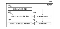
- FIG. 4 is a diagram showing an example of a functional configuration of the control unit 131 in the server device 104 shown in FIG.
- the control unit 131 of the server device 104 includes, for example, a wake-up time acquisition unit 401, a wake-up time set temperature acquisition unit 402, a wake-up mode information acquisition unit 403, and a startup time acquisition unit 404. ..
- the alarm time acquisition unit 401 acquires an alarm time. More specifically, for example, the wake-up time acquisition unit 401 acquires the wake-up time (for example, 7:00 AM) transmitted from the mobile terminal 103.
- the wakeup time set temperature acquisition unit 402 acquires the wakeup time set temperature. More specifically, for example, the wake-up time set temperature acquisition unit 402 acquires the wake-up time set temperature (for example, 25° C.) transmitted from the mobile terminal 103. Note that, without being limited to this, the wake-up time set temperature acquisition unit 402 may acquire, for example, the set temperature set in the air conditioning apparatus 101 at the past startup time from the air conditioning apparatus 101 as the wake-up time set temperature. .. Furthermore, the wake-up time set temperature acquisition unit 402 is based on the indoor temperature, the outdoor temperature, the temperature normally used in the air-conditioning apparatus 101 (the previous set temperature, the average of the set temperatures of the past several times, etc.) and the like. Alternatively, the alarm time setting temperature may be predicted. This prediction process may be processed by the server device 104, for example. As a result, the user does not need to set the wake-up time set temperature, which improves convenience.
- the wake-up time set temperature acquisition unit 402 acquires the wake-
- the alarm mode information acquisition unit 403 acquires the alarm mode information. More specifically, for example, the wake-up mode information acquisition unit 403 acquires the wake-up mode information (for example, energy saving mode) transmitted from the mobile terminal 103.
- this alarm mode may be set in advance by, for example, a remote controller in the air conditioning apparatus 101, or the server apparatus 104 stores the operation record of the past air conditioning apparatus 101, and the server apparatus 104 uses the record as a result. It may be configured to set. This eliminates the need for the user to set each time, improving convenience. Further, for example, the user may arbitrarily set the wake-up mode by using the remote controller attached to the air conditioner 101.
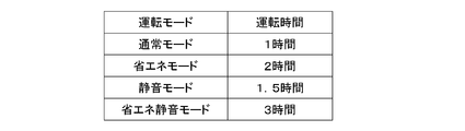
- the startup time acquisition unit 404 acquires the startup time for starting the air conditioning apparatus 101 based on the alarm mode information and the alarm time. More specifically, the activation time acquisition unit 404 acquires the driving time based on the alarm mode information, for example, by referring to the driving time information shown in FIG. 5, and based on the acquired driving time and the alarm time, Get the start time.
- the driving time information is, for example, information in which a driving mode selected in the wake-up mode and a driving time representing a driving time in each driving mode are associated with each other, for example, from a result obtained by an experiment or a simulation. It is set in advance and stored in the storage unit 132.
- the activation time acquisition unit 404 acquires the operation time: 2 hours in which the continuous mode corresponds to the energy saving mode, as shown in FIG. 5, since the alarm mode information is the energy saving mode. Then, since the wake-up time is 7:00 AM, the start-up time acquisition unit 304 subtracts the operating time: 2 hours and acquires the start-up time: AM5:00, which indicates the time when the air conditioning apparatus 101 is started.
- the above operating time is not limited to the above, and may be calculated based on, for example, the temperature of the bedroom, the outside temperature, the set temperature of the alarm clock, and the like.
- the operating time required to adjust to the wake-up time set temperature may be predicted from the wake-up time set temperature and the temperature and/or the outside air temperature acquired from the temperature sensor provided in the air conditioner.
- the operation control unit 405 controls the compressor 115 and the fan 114 in the air conditioner 101 to air-condition the bedroom based on the wake-up time, the wake-up time set temperature, the wake-up mode information, and the start-up time, for example.
- the air conditioner 101 is controlled based on the operating conditions in each operation mode of the alarm mode shown in the table of FIG. This operating condition is set in advance and is stored in, for example, the storage unit 112. The details of each operation mode selected in the alarm mode are as follows.
- the preset rotation speed of the compressor 115 (“high” above the rated compressor rotation speed) and the preset rotation speed of the fan 114 (“high” above the rated fan rotation speed).
- the required capacity is determined according to the number of tatami mats, and the rated capacity is displayed for air conditioners as a guide.
- the measurement method is determined by JIS C9612.
- the compressor speed at that time is called the rated compressor speed, and the fan speed is called the rated fan speed.
- the compressor speed in order to cool (warm) the room quickly, the compressor speed may be set to a high speed equal to or higher than the rated compressor speed, and the compressor speed may be reduced after the temperature difference in the room becomes small.
- the fan rotation speed in the normal mode, may be set to a high rotation speed equal to or higher than the rated fan rotation speed, and the fan rotation speed may be lowered after the temperature difference in the room becomes small.
- the rotation speed of the compressor 115 is set to "low” lower than the rated compressor rotation speed from the start time to the wake-up time, and the rotation speed of the fan 114 is set to the rated fan rotation speed.
- the operation is controlled at the above "high”.
- the rated fan rotation speed may be the maximum rotation speed of the fan.
- the rotation speed of the fan 114 is set to “low” lower than the rated fan rotation speed from the start time to the wake-up time, and the rotation speed of the compressor 115 is set to the rated compressor rotation speed.
- the operation is controlled at the above "high”.
- the rotation speed of the fan is reduced and the air volume is reduced, so it takes more time to adjust the temperature to a predetermined temperature than in the normal mode, but the noise caused by the fan can be reduced.
- the rotation speed of the fan in this silent mode is preferably the minimum rotation speed at which the fan can operate.
- the rotation speed of the compressor is set to "low” and the rotation speed of the fan is set to "low” from the start time to the wake-up time. is there.
- this energy-saving silent mode it takes more time to adjust the temperature to a predetermined temperature than in the energy-saving mode and the silent mode.
- each operation mode is not limited to the above, and various modifications are possible.
- the rotation speeds of the compressor 115 and the fan 114 in each operation mode may be adjusted according to the temperature to be adjusted, the time for adjustment, and the like.
- a rapid mode in which the number of rotations of the compressor 115 and the fan 114 is maximized and air conditioning is performed rapidly may be added as an operation mode.
- the operating conditions in each operation mode are not limited to the operating conditions shown in FIG.
- the above operating conditions may be set more finely, or may be set according to the temperature of the bedroom, the outside air temperature, the alarm time setting temperature, and the like.
- the operation control unit 405 activates the air conditioner 101 at the activation time (AM5:00), and based on the energy saving mode, referring to FIG. 6, changes the rotation speed of the compressor 115 to the rated compressor rotation speed.
- the number of rotations of the fan 114 is controlled to be “low”, which is lower than the number, and is “high”, which is equal to or higher than the rated fan rotation number.
- the bedroom is air-conditioned so as to reach the set temperature (25° C.) at the wake-up time (AM 7:00).
- the operation control unit 405 may adjust the temperature of the bedroom at the wake-up time to the wake-up time set temperature based on the outside air temperature, the temperature of the bedroom, the wake-up time set temperature, and the like. Thereby, it is possible to adjust the wake-up time set temperature at the wake-up time in consideration of the influence of the outside air temperature and the temperature of the bedroom.
- the temperature is adjusted by the air conditioner 101 has been described, but the present invention is not limited to this, and, for example, humidity can be adjusted in the same manner as the temperature.
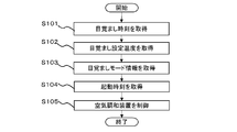
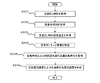
- FIG. 7 is a figure which shows an example of the flow of a process of the air conditioning apparatus system in this embodiment.
- the wake-up time acquisition unit 401 acquires the wake-up time (S101).
- the wake-up time set temperature acquisition unit 402 acquires the wake-up time set temperature (S102).
- the wake-up mode information acquisition unit 403 acquires the wake-up mode information (S103).
- the activation time acquisition unit 404 acquires the activation time (S104).
- the operation control unit 405 controls the air conditioner 101 based on the wake-up time, the wake-up time set temperature, the wake-up mode information, and the start-up time, and operates the compressor 115 and the fan 114, for example, to adjust the temperature of the bedroom. Yes (S105).
- the above flow can be changed as appropriate, and for example, S101 and S102 may be interchanged.
- control of the air conditioning apparatus 101 in S105 is performed, for example, in accordance with the performance of the air conditioning apparatus 101, the environment around the air conditioning apparatus 101, and the like of the compressor 115 and the fan 114 according to the alarm mode information. You may control each part of the harmony device 101. Accordingly, for example, the energy saving effect can be enhanced in the energy saving mode, and the silent effect can be enhanced in the silent mode.
- the alarm time set temperature acquisition unit 402 may be configured to correct the acquired alarm time set temperature.
- the wake-up time set temperature acquisition unit 402 corrects the acquired wake-up time set temperature by a predetermined value (for example, 2° C.).
- a predetermined value for example, 2° C.
- the temperature of the bedroom at the wake-up time is adjusted to be higher than the wake-up time set temperature by a predetermined value, so that it is possible to urge the user to rise in body temperature to wake up the user more comfortably. be able to.
- the temperature is corrected to be high in this way, for example, it is preferable that the temperature is gradually increased from a predetermined time (for example, one hour) before the wake-up time.
- the user since the temperature of the bedroom is adjusted to the wake-up time set temperature at the wake-up time, the user can wake up comfortably.
- the present invention is not limited to the above-described embodiment, and is substantially the same configuration as the configuration shown in the above-described embodiment, a configuration having the same action and effect, or a configuration capable of achieving the same object. May be replaced with.
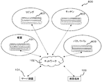
- the air conditioner system 800 of the present embodiment has a first linked air conditioner 801 installed in a living room and a first linked air conditioner 801 installed in a living room in addition to the air conditioner 101 installed in the bedroom.
- the second combined air conditioner 802 and the third combined air conditioner 803 installed in the bath/toilet.
- the first cooperative air conditioner 801 performs air conditioning of the living room
- the second cooperative air conditioner 802 performs air conditioning of the kitchen
- the third cooperative air conditioner 803 performs air conditioning of the bath/toilet. Since each of the linked air conditioners 801, 802, and 803 has the same configuration as the air conditioner 101, its details are omitted.
- the air conditioner 101 and the associated air conditioners 801, 802, and 803 are each provided with an ID, for example, and the installation location or the like is identified by this ID. Furthermore, the installation location of each of these air conditioners is identified, for example, by the user registering at the time of purchase.
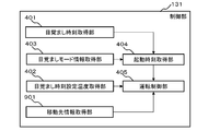
- FIG. 9 is a diagram showing an example of a functional configuration of the control unit 131 of the server device 104 according to the present embodiment.
- the control unit 131 according to the present embodiment further includes a move destination information acquisition unit 901 in the control unit of the server device 104 according to the first embodiment.
- the destination information acquisition unit 901 acquires destination information indicating a room to which the user moves after waking up in the bedroom.
- the destination information in which the order of the rooms to be moved by the user is associated may be acquired.
- the destination information is, for example, information input by the user through the input unit 124 of the mobile terminal 103, information preset by the user's action pattern, information set by the analysis result based on the movement history of the user's mobile terminal, or the like. , But is not limited thereto.
- the activation time acquisition unit 404 acquires, on the basis of the destination information, the associated air conditioner activation time for activating the associated air conditioner in the room that is the destination.
- This linked air conditioner startup time may be acquired in the same manner as when the startup time in the first embodiment is acquired.
- the operation control unit 405 controls the linked air conditioner installed in the room represented by the destination information based on the alarm time set temperature, the linked air conditioner startup time, the alarm time set temperature, and the destination information.
- the temperature of the room in which the air conditioner 101 and the associated air conditioners 801, 802, and 803 are installed is adjusted to the set alarm clock times.
- each linked air conditioner 801, 802.803 may be different for each room to which it is moved. This can further improve the comfort of the user.
- the set temperature of each room may be set, for example, by the control unit 131 of the server device 104 according to the alarm time set temperature set in the bedroom. As a result, the user does not need to set the temperature of each room individually, which improves convenience.
- FIG. 10 is a figure which shows an example of the flow of a process of the air conditioning apparatus system in this embodiment.
- the wake-up time acquisition unit 401 acquires the wake-up time (S201).
- the destination information acquisition unit 901 acquires the destination information (S202).
- the alarm time set temperature acquisition unit 402 acquires the alarm time set temperature (S203).
- the alarm mode information acquisition unit 403 acquires the alarm mode information (S204).
- the activation time acquisition unit 404 acquires the activation time of the air conditioner 101 and the associated air conditioning device activation time (S205).
- the operation control unit 405 controls the air conditioner 101 and each associated air conditioner 801, 802, 803 based on the alarm time, the alarm time set temperature, the alarm mode information, the activation time, and the associated air conditioner activation time, The temperature of the bedroom and the room in which each linked air conditioner is installed is adjusted (S206).
- the wake-up time set temperature acquisition unit 402 sets the wake-up time set temperature of the air conditioning apparatus 101 and the wake-up time set temperature of each of the linked air conditioning apparatuses 801, 802, and 803 separately, for example, so that they are different from each other. You may get it.
- the air conditioning by the associated air conditioning devices 801, 802, and 803 at the destination is not limited to the following, and various modifications can be made.
- the operation control unit 405 controls the linked air conditioning apparatus 801 installed in the living room to adjust the temperature of the living room.
- the alarm time set temperature A in the linked air conditioner 801 is set to be lower than the alarm time set temperature set in the air conditioner 101 installed in the bedroom by a predetermined temperature in summer, for example.
- the operation control unit 405 predicts the time from waking up to going to the living room, and controls the cooperative air conditioning apparatus 801 so that the temperature of the living room becomes the above-mentioned wake-up time temperature A at the wake-up time. Therefore, the starting time of the living room is later than the starting time of the air conditioner in the bedroom.
- the set temperature of the linked air conditioner 801 is returned to the set temperature that was set before the wake-up time set temperature A, for example, in the silent mode.
- the air conditioner 801 is controlled.
- the cooperative air conditioner 801 may be stopped. As a result, the user is urged to raise his/her body temperature at the wake-up time, can wake up comfortably, and can settle in the living room at the set temperature for daily living and can spend comfortably.
- the operation control unit 405 controls the linked air conditioning apparatus 802 set in the kitchen to adjust the temperature of the kitchen.
- the alarm time set temperature B in the linked air conditioning apparatus 802 is set lower than the alarm time set temperature set in the air conditioning apparatus 101 installed in the bedroom by a predetermined temperature, for example.
- the operation control unit 405 controls the cooperative air conditioning apparatus 802 so that the temperature of the kitchen becomes the above-mentioned alarm time temperature B at the alarm time.
- the set temperature of the linked air conditioner 802 is returned to the set temperature set before the wake-up time set temperature B, and, for example, the linked air is set in the silent mode.
- the harmony device 802 is controlled. As described above, since cooking and the like may occur in the kitchen and heat may be generated, it is preferable to set the cooperative air conditioning device wake-up time set temperature lower than the wake-up time set temperature. In addition, when the alarm time is exceeded, the cooperative air conditioner 802 may be stopped.
- the operation control unit 405 controls the linked air conditioner 803 set in the toilet/bus to adjust the temperature of the toilet/bus.
- the alarm time set temperature C in the linked air conditioner 803 is lower than the alarm time set temperature set in the air conditioner 101 installed in the bedroom during heating by a predetermined temperature, and lower than the alarm time set temperature A by a predetermined temperature.
- a predetermined temperature is set higher than the alarm time set temperature set by the air conditioner 101 installed in the bedroom, and set higher than the alarm time set temperature A by a predetermined temperature.
- the operation control unit 405 controls the cooperative air conditioning apparatus 803 so that the temperature of the toilet/bath becomes the above-mentioned alarm time temperature C at the alarm time.
- energy-saving driving can be performed without significantly impairing the comfort of the toilet/bus that has a low usage time.
- the set temperature of the linked air conditioner 803 is returned to the set temperature before being set to the wake-up time set temperature C, for example, in the silent mode.
- the cooperative air conditioner 803 is controlled.
- the cooperative air conditioner 803 may be stopped.
- the startup time acquisition unit 404 is configured to acquire the linked air conditioning device startup time based on the alarm mode information acquired by the alarm mode information acquisition unit 403, but is not limited to this.
- energy saving may be achieved by presetting the cooperative air conditioners 801, 802, 803 to operate in the energy saving mode. This is because there is no need to drive in the silent mode because the user is not sleeping in the destination room.
- the start time of each linked air conditioner 801, 802.803 may be different from the start time of the air conditioner 101 set in the bedroom, or may be different for each linked air conditioner.
- the start time of each associated air conditioner 801, 802.803 may be set according to the performance of each associated air conditioner 801, 802.803 and the environment of the room in which it is installed. ..
- the start time of each linked air conditioning apparatus 801, 802.803 is set to the air conditioning apparatus in consideration of the time for moving.
- the air conditioning of the room where the user heads after waking up is performed according to the lifestyle (action) of the user. be able to. Thereby, the comfort of the user can be improved.
- the present invention is not limited to the above-described embodiment, and can be replaced with a configuration substantially the same as the configuration shown in the above-described embodiment, a configuration having the same operation effect, or a configuration capable of achieving the same object. May be.
- the configuration may be modified as described below.
- the configuration may be as in the first modification.
- the control unit 131 of the server device 104 predicts a time when the user goes to bed based on the wake-up time, and the temperature of the bedroom becomes a predetermined temperature at the bedtime based on the bedtime.
- the air conditioner 101 is controlled as described above.
- the temperature of the bedroom is adjusted to a predetermined temperature at the bedtime, for example, the alarm time is replaced with the bedtime, and the temperature of the bedroom is adjusted as in the present embodiment. Thereby, the temperature of the bedroom can be adjusted to a comfortable temperature for the user at bedtime.
- the bedtime of the user may be predicted, for example, from the behavior pattern of the user, or may be predicted from the information about the room other than the bedroom, such as the operating status of the linked device set in the room other than the bedroom.
- the predetermined temperature of the bedroom at the bedtime may be, for example, the temperature set by the user with the mobile terminal or the air conditioner, or may be set with the air conditioner operating in a room other than the bedroom, for example. You may acquire and set the temperature which is.
- the predetermined temperature is set in the cooperative air conditioner operating in a room other than the bedroom.
- the preset temperature may be set.
- the temperature of the bedroom can be adjusted to a comfortable temperature that better suits the taste of the user.
- the air conditioning apparatus 101 in the energy saving mode according to the bedtime. Further, after bedtime, the air conditioner 101 may be controlled in the silent mode to control the set temperature in the bedroom. As a result, it is possible to prevent the user from sleeping.
- the louver and the fan of the air conditioning apparatus 101 are controlled at the wake-up time so that the air is blown toward the sleeping user.
- the fan rotation speed may be set to a high rotation speed from the silent mode at the wake-up time to intentionally increase the sound (produce a blowing noise).
- the user is prompted to wake up not by the unpleasant electronic sound of the alarm clock or the like but by the blowing noise that is closer to a natural sound, so that the user can wake up comfortably.
- each process is performed by the control unit of the server device, each process may be performed by another control unit provided in the air conditioning apparatus 101 or the like, for example. ..
- the control unit of the air conditioning apparatus 101 includes the wakeup time acquisition unit 401, the wakeup time set temperature acquisition unit 402, the wakeup mode information acquisition unit 403, the activation time acquisition unit 404, the operation control unit 405, the destination information acquisition unit 901, and the like. You may comprise so that each functional block of may be provided.
Landscapes
- Engineering & Computer Science (AREA)
- Chemical & Material Sciences (AREA)
- Combustion & Propulsion (AREA)
- Mechanical Engineering (AREA)
- General Engineering & Computer Science (AREA)
- Physics & Mathematics (AREA)
- Human Computer Interaction (AREA)
- General Physics & Mathematics (AREA)
- Thermal Sciences (AREA)
- Air Conditioning Control Device (AREA)
Abstract
ユーザーの起床時に、快適な温度に調節する空気調和装置システムを提供する。空気調和装置システムは、目覚まし時刻を取得する目覚まし時刻取得手段と、前記目覚まし時刻に基づいて、第1の部屋に設置された空気調和装置を起動させる起動時刻を取得する起動時刻取得手段と、前記目覚まし時刻および前記起動時刻に基づいて、前記空気調和装置を制御する運転制御手段と、を有する。
Description
本発明は、空気調和装置システムに関する。本願は、2019年1月28日に、日本に出願された特願2019-11902号に基づく優先権を主張するものであり、その内容をここに援用する。
例えば、特許文献1には、目覚まし時計のアラーム時刻に冷暖房の運転が開始される空気調和装置が開示されている。
しかしながら、特許文献1の空気調和装置においては、アラーム時刻に運転が開始されるため、ユーザーが起床するアラーム時刻に快適な温度に調節することは困難であった。本発明の一形態は、ユーザーの起床時に、快適な温度に調節する空気調和装置システムを提供することを目的とする。
本発明の一形態の空気調和装置システムは、空気調和装置システムは、目覚まし時刻を取得する目覚まし時刻取得手段と、前記目覚まし時刻に基づいて、第1の部屋に設置された空気調和装置を起動させる起動時刻を取得する起動時刻取得手段と、前記目覚まし時刻および前記起動時刻に基づいて、前記空気調和装置を制御する運転制御手段と、を有する。
以下、本発明の実施形態について、図面を参照しつつ説明する。なお、図面については、同一又は同等の要素には同一の符号を付し、重複する説明は省略する。
(第1の実施形態)
図1は、本実施の形態に係る空気調和装置システムの一例を示す図である。
図1は、本実施の形態に係る空気調和装置システムの一例を示す図である。
図1に示すように、本実施形態における空気調和装置システム100は、空気調和装置101、ネットワーク102、携帯端末103、サーバ装置(情報処理装置)104を含む。これら空気調和装置101、携帯端末103、サーバ装置104は、ネットワーク102を介して接続されている。空気調和装置101は、例えば、エアコン等であり、ユーザーの寝室に設置され、当該寝室の空調を行う。ネットワーク102は、例えば、インターネットやBluetooth(登録商標)等に相当する。携帯端末103は、例えば、スマートフォン、リモコン等の機器であり、空気調和装置101において設定される目覚まし時刻等をユーザーが入力するための機器である。なお、本実施形態における上記携帯端末103は、例えば、目覚まし時刻を送信できるものであればよく、ネットワーク102に接続された目覚まし時計等であってよい。なお、空気調和装置101および携帯端末103は、例えば、ID等で識別され、空気調和装置101に携帯端末103が登録されている。
次に、本実施の形態における空気調和装置101の制御部111を中心とした主な構成の一例について説明する。空気調和装置101は、例えば、制御部111、記憶部112、通信部113、ファン114、コンプレッサ115、温度センサ116等を含む。制御部111は、例えばCPU、MPU等であって、記憶部112に格納されるプログラムに従って各種の情報処理を実行する。記憶部112は、例えばフラッシュメモリやRAM等であって、制御部111によって実行されるプログラムや、各種のデータを保持する。また、記憶部112は、制御部111のワークメモリとしても動作する。通信部113は、インターフェース等であって、ネットワーク102を介して、携帯端末103、サーバ装置104と通信する。なお、空気調和装置101は、上記の各部の他に、例えばルーバー、イオン発生装置等を含み、それぞれ制御部111に接続され、制御される。
次に、本実施の形態における携帯端末103の制御部121を中心とした主な構成の一例について説明する。携帯端末103は、上記空気調和装置101と同様に、例えば、制御部121、記憶部122、通信部123、入力部124を含む。なお、制御部121、記憶部122、通信部123の主な構成は上記空気調和装置101と同様であるので、説明を省略する。また、入力部124からは、ユーザーにより目覚まし時刻、設定温度、運転モード等が入力される。
次に、本実施の形態におけるサーバ装置104の制御部131を中心として主な構成の一例について説明する。サーバ装置104は、例えば、制御部131、記憶部132、通信部133を含む。なお、制御部131、記憶部132、通信部133の主な構成は上記空気調和装置101と同様であるので、説明を省略する。
図2は、前記空気調和装置101の具体的な一例を示す図である。空気調和装置101は、例えば、室内機20および室外機30を有する。
室内機20は、内部に熱交換器(不図示)、ファン114(図1参照)、吹出し口5に設けられたルーバー18を有する。ファン114を動作させることにより、吹出し口5から送風され、ルーバー18によりその風向きが制御される。
室外機30は、内部にコンプレッサ115(図1参照)を有する。熱交換器とコンプレッサ115とは接続される。コンプレッサ115が駆動されると冷凍サイクルが運転され、熱交換器が吹出し口5から吹出される空気(風)の熱交換を行う。これにより、吹出し口5から冷気または暖気が吹出され、空気調和装置101は設置された空間の空気調和を行う。なお、上記空気調和装置101の構成は一例であって、これに限定されるものではない。なお、この空気調和装置101は、例えば、付属のリモコンにおり、温度、風量、運転モードが設定されるように構成されていてよい。
図3は、図1に示す携帯端末103における制御部121の機能的構成の一例を示す図である。図3に示すように、本実施形態における携帯端末103の制御部121は、例えば、携帯端末側目覚まし時刻取得部301、携帯端末側目覚まし時刻設定温度取得部302、携帯端末側モード情報取得部303を含む。なお、例えば、ユーザーは、携帯端末103の入力部124から、目覚まし時刻、目覚まし時刻設定温度、後述する目覚ましモードを入力することができる。
携帯端末側目覚まし時刻取得部301は、例えば、ユーザーが目を覚ましたい時刻を表す目覚まし時刻を取得する。より具体的には、例えば、携帯端末側目覚まし時刻取得部301は、携帯端末103の入力部124からユーザーにより入力された目覚まし時刻(例えば、AM7:00)を取得する。
携帯端末側目覚まし時刻設定温度取得部302は、例えば、目覚まし時刻設定温度を取得する。目覚まし時刻設定温度は、目覚まし時刻に空気調和装置101が調節するように設定された温度を表す。より具体的には、例えば、携帯端末側目覚まし時刻設定温度取得部302は、携帯端末103の入力部124からユーザーにより入力された目覚まし時刻設定温度(例えば、25℃)を取得する。
携帯端末側目覚ましモード情報取得部303は、目覚ましモード情報を取得する。目覚ましモード情報は、目覚まし時刻設定温度に調節する際に空気調和装置101にて運転される運転モードを表す。この目覚ましモード情報は、例えば、通常モード、省エネオード、静音モード、省エネ静音モード等を含む運転モードから選択される。これら各運転モードについては、後述する。より具体的には、例えば、携帯端末側目覚ましモード情報取得部303は、ユーザーが入力部124で選択することにより入力された目覚ましモード情報(例えば、省エネモード)を取得する。
そして、上記携帯端末103は、取得した各情報(目覚まし時刻、目覚まし時刻設定温度等)をサーバ装置104に送信する。
図4は、図1に示すサーバ装置104における制御部131の機能的構成の一例を示す図である。図3に示すように、本実施形態におけるサーバ装置104の制御部131は、例えば、目覚まし時刻取得部401、目覚まし時刻設定温度取得部402、目覚ましモード情報取得部403、起動時刻取得部404を含む。
目覚まし時刻取得部401は、目覚まし時刻を取得する。より具体的には、例えば、目覚まし時刻取得部401は、携帯端末103から送信された目覚まし時刻(例えば、AM7:00)を取得する。
目覚まし時刻設定温度取得部402は、目覚まし時刻設定温度を取得する。より具体的には、例えば、目覚まし時刻設定温度取得部402は、携帯端末103から送信された目覚まし時刻設定温度(例えば、25℃)を取得する。なお、これ限らず、目覚まし時刻設定温度取得部402は、例えば、過去の起動時刻において空気調和装置101で設定されている設定温度を、目覚まし時刻設定温度として空気調和装置101から取得してもよい。さらに、前記目覚まし時刻設定温度取得部402は、室内温度、室外気温、空気方調和装置101で普段使用している温度(前回の設定温度、過去数回の設定温度の平均等)等に基づいて、目覚まし時刻設定温度を予測処理してもよい。この予測処理は、例えばサーバ装置104で処理されてもよい。これにより、ユーザーは、目覚まし時刻設定温度を設定する必要はなく利便性が向上する。
目覚ましモード情報取得部403は、目覚ましモード情報を取得する。より具体的には、例えば、目覚ましモード情報取得部403は、携帯端末103から送信された目覚ましモード情報(例えば、省エネモード)を取得する。なお、この目覚ましモードは、例えば、空気調和装置101におけるリモコンにより予め設定されてもよいし、また、過去の空気調和装置101における運転実績をサーバ装置104が記憶し、この実績よりサーバ装置104が設定するように構成してもよい。これにより、ユーザーが都度設定する必要はなくなり、利便性が向上する。また、例えば、上記空気調和装置101における付属のリモコンで、ユーザーが任意に目覚ましモードを設定するように構成してもよい。
起動時刻取得部404は、目覚ましモード情報および目覚まし時刻に基づいて、空気調和装置101を起動させる起動時刻を取得する。より具体的には、起動時刻取得部404は、目覚ましモード情報に基づいて、例えば、図5に示す運転時間情報を参照して運転時間を取得し、取得した運転時間および目覚まし時刻に基づいて、起動時刻を取得する。上記運転時間情報は、例えば、目覚ましモードで選択される運転モードと、各運転モードで運転する時間を表す運転時間とが関連付けられた情報であり、例えば、実験やシミュレーション等で得られた結果より予め設定され、記憶部132に格納されている。上記の例では、起動時刻取得部404は、目覚ましモード情報が省エネモードであるので、図5に示すように、運連モードが省エネモードに対応する運転時間:2時間を取得する。そして、起動時刻取得部304は、目覚まし時刻がAM7:00であるので、運転時間:2時間を差し引いて、空気調和装置101が起動する時刻を表す起動時刻:AM5:00を取得する。
なお、上記運転時間は、上記に限らず、例えば、寝室の温度、外気温、目覚まし時刻設定温度等に基づいて、算出してもよい。例えば、目覚まし時刻設定温度と、空気調和装置に設けられた温度センサから取得した温度および/または外気温とから、目覚まし時刻設定温度に調節するために必要な運転時間を予測してもよい。
運転制御部405は、目覚まし時刻、目覚まし時刻設定温度、目覚ましモード情報、起動時刻に基づいて、例えば、空気調和装置101におけるコンプレッサ115およびファン114を制御して、寝室を空気調和する。なお、このコンプレッサ115およびファン114を制御する際には、例えば、図6の表に示す目覚ましモードの各運転モードにおける動作条件に基づいて、空気調和装置101を制御する。この動作条件は、予め設定され、例えば記憶部112に格納されている。また、上記目覚ましモードで選択される各運転モードの詳細は、以下の通りである。
通常モードは、空気調和装置101において、例えば予め設定されたコンプレッサ115の回転数(定格コンプレッサ回転数以上の「高」)および予め設定されたファン114の回転数(定格ファン回転数以上の「高」)で制御する運転である。一般的に、部屋畳数に応じた必要な能力が決っており、その目安としてエアコンでは定格能力を表示している。測定方法はJISC9612により決められた測定方法で測定し、その時のコンプレッサ回転数を定格コンプレッサ回転数、ファン回転数を定格ファン回転数という。なお、通常モードでは、早く部屋を冷やす(暖める)ために、コンプレッサ回転数を定格コンプレッサ回転数以上の高回転数にし、部屋の温度差が小さくなってからコンプレッサ回転数を下げればよい。同様に、通常モードでは、ファン回転数も定格ファン回転数以上の高回転数にし、部屋の温度差が小さくなってからファン回転数を下げるようにすればよい。
省エネモードは、空気調和装置101において、起動時刻から目覚まし時刻までの間、例えばコンプレッサ115の回転数を定格コンプレッサ回転数よりも低い「低」に設定し、ファン114の回転数を定格ファン回転数以上の「高」で制御する運転である。この省エネモードでは、コンプレッサの回転数を低くしているため、通常モードに比べて、所定の温度に調節するまでは時間がかかるが、空気調和装置101の消費電力量を低下させることができる。なお、上記定格ファン回転数はファンの最大回転数であってもよい。
静音モードは、空気調和装置101において、起動時刻から目覚まし時刻までの間、例えばファン114の回転数を定格ファン回転数よりも低い「低」に設定し、コンプレッサ115の回転数を定格コンプレッサ回転数以上の「高」で制御する運転である。この静音モードでは、ファンの回転数を低くして風量が低くなっているため、通常モードに比べて、所定の温度に調節するまでは時間がかかるが、ファンによる騒音を低下させることができる。なお、この静音モードにおけるファンの回転数は、ファンが動作可能な最小の回転数であることが好ましい。
省エネ静音モードは、空気調和装置101において、起動時刻から目覚まし時刻までの間、例えばコンプレッサの回転数を「低」に設定し、さらにファンの回転数を「低」に設定して制御する運転である。この省エネ静音モードでは、上記省エネモードおよび静音モードよりもさらに所定の温度に調節するまでに時間がかかるが、通常モードに比べて、省エネおよび静音を両立することができる。
なお、各運転モードは、上記に限定されるものではなく、種々の変形が可能である。例えば、各運転モードにおいてコンプレッサ115およびファン114の回転数を、調節する温度、調節するための時間等に応じて、調整するように構成してもよい。さらに、例えば、コンプレッサ115およびファン114の回転数を最大にして急速に空調する急速モードを運転モードとして追加してもよい。
また、各運転モードにおける動作条件は、図5の動作条件に限定されるものではない。例えば、上記動作条件は、さらに細かく設定されていてもよいし、寝室の温度、外気温、目覚まし時刻設定温度等に応じて設定されていてもよい。
運転制御部405は、上記の例の場合、起動時刻(AM5:00)に空気調和装置101を起動させ、省エネモードに基づいて、図6を参照して、コンプレッサ115の回転数を定格コンプレッサ回転数よりも低い「低」、ファン114の回転数を定格ファン回転数以上の「高」にて制御する。そして、目覚まし時刻(AM7:00)に設定温度(25℃)になるように寝室を空気調和する。
また、運転制御部405は、外気温、寝室の温度、目覚まし時刻設定温度等に基づいて、上記目覚まし時刻に寝室の温度が目覚まし時刻設定温度になるように調節してもよい。これにより、外気温、寝室の温度にも影響を考慮して、目覚まし時刻に目覚まし時刻設定温度に調節することができる。なお、上記では、空気調和装置101により温度を調節する例を説明したが、これに限らず、例えば、湿度についても温度と同様に調節することができる。
次に、本実施形態における空気調和装置システムにおける処理のフローの一例について説明する。図7は本実施形態における空気調和装置システムの処理のフローの一例を示す図である。
図7に示すように、目覚まし時刻取得部401は、目覚まし時刻を取得する(S101)。目覚まし時刻設定温度取得部402は、目覚まし時刻設定温度を取得する(S102)。目覚ましモード情報取得部403は、目覚ましモード情報を取得する(S103)。起動時刻取得部404は、起動時刻を取得する(S104)。運転制御部405は、目覚まし時刻、目覚まし時刻設定温度、目覚ましモード情報、起動時刻、に基づいて、空気調和装置101を制御し、例えば、コンプレッサ115およびファン114を動作させて、寝室の温度を調節する(S105)。なお、上記のフローは適宜変更可能であり、例えば、S101とS102が入れ替わってもよい。また、S105における空気調和装置101の制御は、例えば、上記目覚ましモード情報に合わせて、空気調和装置101の性能や空気調和装置101の周囲の環境等に応じて、コンプレッサ115およびファン114等の空気調和装置101の各部を制御してもよい。これにより、例えば、省エネモードであれば省エネ効果が高くなるように、静音モードであれば静音効果が高くなるようにできる。
例えば、S103において、目覚まし時刻設定温度取得部402は、取得した目覚まし時刻設定温度を補正するように構成してもよい。例えば、目覚まし時刻設定温度取得部402は、取得した目覚まし時刻設定温度を所定値(例えば、2℃)高く補正する。これにより、例えば、目覚まし時刻における寝室の温度が、目覚まし時刻設定温度よりも所定値高く調節されるため、ユーザーの起床に向けて体温の上昇を促すことができるため、より快適にユーザーを覚醒させることができる。このように温度を高く補正する場合には、例えば、目覚まし時刻の所定時間前(例えば、1時間前)から徐々に温度を上昇させるように調節することが好ましい。
本発明の空気調和装置システムによれば、目覚まし時刻に寝室の温度を目覚まし時刻設定温度に調節するため、ユーザーは快適に起床することができる。
本発明は、上記実施の形態に限定されるものではなく、上記実施の形態で示した構成と実質的に同一の構成、同一の作用効果を奏する構成又は同一の目的を達成することができる構成で置き換えてもよい。
(第2の実施形態)
次に、第2の実施形態について説明する。なお、下記において第1の実施形態と同様である点については説明を省略する。本実施形態は、空気調和装置101以外に、1つまたは複数の連携空気調和装置を有する点で、第1の実施形態と異なる。
次に、第2の実施形態について説明する。なお、下記において第1の実施形態と同様である点については説明を省略する。本実施形態は、空気調和装置101以外に、1つまたは複数の連携空気調和装置を有する点で、第1の実施形態と異なる。
本実施形態の空気調和装置システム800は、例えば、図8に示すように、寝室に設置された空気調和装置101の他に、リビングに設置された第1の連携空気調和装置801、キッチンに設置された第2の連携空気調和装置802、バス/トイレに設置された第3の連携空気調和装置803を含む。第1の連携空気調和装置801はリビングの空調を行い、第2の連携空気調和装置802はキッチンの空調を行い、第3の連携空気調和装置803はバス/トイレの空調を行う。なお、各連携空気調和装置801・802・803は、空気調和装置101と同様の構成であるのでその詳細については省略する。また、上記空気調和装置101、各連携空気調和装置801・802・803は、例えば、それぞれIDが付与されており、このIDによりその設置場所等が識別されるようになっている。さらにまた、これらの各空気調和装置の設置場所は、例えば、ユーザーが購入時に登録する等により識別されるようになっている。
図9は、本実施形態にかかるサーバ装置104の制御部131の機能的構成の一例を示す図である。本実施形態にかかる制御部131は、第1の実施形態におけるサーバ装置104の制御部において、さらに、移動先情報取得部901を有する。
上記移動先情報取得部901は、ユーザーが寝室で目覚めた後に移動する部屋を表す移動先情報を取得する。なお、複数の部屋に移動する場合には、ユーザーが移動する部屋の順番を関連付けた移動先情報を取得してもよい。なお、この移動先情報は、例えば、ユーザーが携帯端末103の入力部124か入力したもの、ユーザーの行動パターンから予め設定されたもの、ユーザーの携帯端末における移動履歴から分析結果から設定したもの等、ユーザーの行動パターンに基づくものであるが、これらに限定されるものではない。
そして、起動時刻取得部404は、移動先情報に基づいて、移動先である部屋の連携空気調和装置を起動させる連携空気調和装置起動時刻を取得する。この連携空気調和装置起動時刻は、第1の実施形態における起動時刻を取得した場合と同様に取得すればよい。そして、運転制御部405は、目覚まし時刻設定温度、連携空気調和装置起動時刻、目覚まし時刻設定温度、移動先情報に基づいて、移動先情報が表す部屋に設置された連携空気調和装置を制御し、空気調和装置101および各連携空気調和装置801・802・803の設置された部屋の温度を、それぞれに設定された目覚まし時刻設定温度に調節する。
なお、各連携空気調和装置801・802.803における目覚まし時刻設定温度は、移動先の部屋毎に、異なるように構成してもよい。これにより、よりユーザーの快適性を向上させ得る。また、各部屋の設定温度は、例えば、サーバ装置104の制御部131が、寝室に設定された目覚まし時刻設定温度に応じて設定するように構成してよい。これにより、ユーザーは各部屋の温度を個別に設定する必要がなく、利便性が向上する。
次に、本実施形態における空気調和装置システムにおける処理のフローの一例について説明する。図10は本実施形態における空気調和装置システムの処理のフローの一例を示す図である。
図10に示すように、目覚まし時刻取得部401は、目覚まし時刻を取得する(S201)。移動先情報取得部901は、移動先情報を取得する(S202)。目覚まし時刻設定温度取得部402は、目覚まし時刻設定温度を取得する(S203)。目覚ましモード情報取得部403は、目覚ましモード情報を取得する(S204)。起動時刻取得部404は、空気調和装置101の起動時刻および各連携空気調和装置起動時刻を取得する(S205)。運転制御部405は、目覚まし時刻、目覚まし時刻設定温度、目覚ましモード情報、起動時刻、連携空気調和装置起動時刻に基づいて、空気調和装置101および各連携空気調和装置801・802・803を制御し、寝室および各連携空気調和装置が設置された部屋の温度を調節する(S206)。なお、上記のフローは適宜変更可能であり、例えば、S101とS102が入れ替わってもよい。また、S203において、目覚まし時刻設定温度取得部402は、空気調和装置101の目覚まし時刻設定温度、各連携空気調和装置801・802・803の目覚まし時刻設定温度をそれぞれ別個に、例えばそれぞれが異なるように取得してもよい。
ここで、各移動先における連携空気調和装置による空気調和の具体例について、下記に説明する。なお、上記移動先における各連携空気調和装置801・802・803による空気調和は、下記に限定されるものではなく、種々の変更か可能である。
例えば、移動先情報が、リビングを表す場合、運転制御部405は、リビングに設置された連携空気調和装置801を制御して、リビングの温度を調節する。連携空気調和装置801における目覚まし時刻設定温度Aは、例えば、夏であれば、寝室に設置された空気調和装置101で設定された目覚まし時刻設定温度よりも所定温度低く設定される。そして、運転制御部405は、起床してからリビングに行くまでの時間を予測し、目覚まし時刻にリビングの温度を上記目覚まし時刻温度Aになるように、連携空気調和装置801を制御する。そのため、リビングの起動時刻は寝室でのエアコン起動時刻よりも遅くする。目覚まし時刻にリビングを目覚まし時刻設定温度Aに調節した後は、例えば、連携空気調和装置801の設定温度を目覚まし時刻設定温度Aの前に設定されていた設定温度に戻し、例えば、静音モードで連携空気調和装置801を制御する。なお、目覚まし時刻を超過した場合には、連携空気調和装置801を停止してもよい。これにより、ユーザーは、目覚まし時刻には体温上昇が促され、快適に起床でき、リビングでは普段生活する設定温度となり快適に過ごせる。
また、例えば、移動先情報が、キッチンを表す場合、運転制御部405は、キッチンに設定された連携空気調和装置802を制御して、キッチンの温度を調節する。連携空気調和装置802における目覚まし時刻設定温度Bは、例えば、寝室に設置された空気調和装置101で設定された目覚まし時刻設定温度よりも所定温度低く設定される。そして、運転制御部405は、目覚まし時刻にキッチンの温度を上記目覚まし時刻温度Bになるように、連携空気調和装置802を制御する。目覚まし時刻にキッチンを目覚まし時刻設定温度に調節した後は、例えば、連携空気調和装置802の設定温度を目覚まし時刻設定温度Bの前に設定されていた設定温度に戻し、例えば、静音モードで連携空気調和装置802を制御する。このように、キッチンでは、調理等が行われ熱が発生する可能性があるため、連携空気調和装置目覚まし時刻設定温度を目覚まし時刻設定温度よりも低く設定することが好ましい。なお、目覚まし時刻を超過した場合には、連携空気調和装置802を停止してもよい。
さらに、例えば、移動先情報がトイレ/バスを表す場合、運転制御部405は、トイレ/バスに設定された連携空気調和装置803を制御して、トイレ/バスの温度を調節する。連携空気調和装置803における目覚まし時刻設定温度Cは、例えば、暖房時には寝室に設置された空気調和装置101で設定された目覚まし時刻設定温度よりも所定温度低く、目覚まし時刻設定温度Aよりも所定温度低く設定し、一方冷房時には寝室に設置された空気調和装置101で設定された目覚まし時刻設定温度よりも所定温度高く、目覚まし時刻設定温度Aよりも所定温度高く設定される。そして、運転制御部405は、目覚まし時刻にトイレ/バスの温度を上記目覚まし時刻温度Cになるように、連携空気調和装置803を制御する。こうする事で使用時間の低いトイレ/バスの快適性を大きく損なうことなく省エネ運転する事ができる。目覚まし時刻にトイレ/バスを目覚まし時刻設定温度Cに調節した後は、例えば、連携空気調和装置803の設定温度を目覚まし時刻設定温度Cに設定される前の設定温度に戻し、例えば、静音モードで連携空気調和装置803を制御する。なお、目覚まし時刻を超えた場合には、連携空気調和装置803を停止してもよい。
また、上記では、起動時刻取得部404は、目覚ましモード情報取得部403で取得した目覚ましモード情報に基づいて、連携空気調和装置起動時刻を取得するように構成しているが、これに限らず、例えば、連携空気調和装置801・802・803を省エネモードで動作させるように予め設定し、省エネを図ってもよい。これは、移動先の部屋では、ユーザーが寝ていないので、静音モードで運転する必要がないためである。
さらに、各連携空気調和装置801・802.803の起動時刻は、寝室に設定された空気調和装置101の起動時刻と異なっていてもよいし、各連携空気調和装置で異なっていてもよい。例えば、各連携空気調和装置801・802.803における起動時刻は、各連携空気調和装置801・802.803の性能や設置されている部屋の環境に応じて設定されるように構成してもよい。また、例えば、上記のように移動先情報に移動する順番が関連付けている場合には、移動するための時間を考慮して、各連携空気調和装置801・802.803の起動時刻を空気調和装置101の起動時刻よりも遅く設定することで、空気調和装置101の起動時刻に各連携空気調和装置801・802・803を起動させるよりも、省エネを図り得る。
本実施形態における空気調和装置システムによれば、寝室にてユーザーが目を覚ました(起床した)のちの、ユーザーの生活スタイル(行動)に応じて、ユーザーが起床後に向かう部屋の空気調和を行うことができる。これにより、ユーザーの快適性を向上させることができる。
本発明は、上記実施形態に限定されるものではなく、上記実施形態で示した構成と実質的に同一の構成、同一の作用効果を奏する構成又は同一の目的を達成することができる構成で置き換えてもよい。例えば、下記変形例のように構成してもよい。
また、例えば、第1の変形例のように構成してもよい。第1の変形例では、サーバ装置104の制御部131は、目覚まし時刻に基づいて、ユーザーが就寝する時刻を予測し、この就寝時刻に基づいて、就寝時刻に寝室の温度が所定の温度になるように空気調和装置101を制御する。この就寝時刻に寝室の温度が所定の温度に調節する際には、例えば、目覚まし時刻を就寝時刻に置き換えて、本実施形態と同様に寝室の温度を調節する。これにより、就寝時に寝室の温度をユーザーの快適な温度に調節することができる。なお、ユーザーの就寝時刻は、例えば、ユーザーの行動パターンから予測してもよいし、寝室以外の部屋に設定された連携機器の動作状況等の寝室以外の部屋の情報から予測してもよい。また、上記就寝時刻に寝室の温度の所定の温度は、例えば、ユーザーが携帯端末や空気調和装置で設定した温度であってよいし、例えば寝室以外の部屋で稼働中の空気調和装置で設定されている温度を取得して設定してもよい。
また、第1の変形例においては、第2の実施形態のように、連携空気調和装置を有する場合に、例えば、上記所定の温度を、寝室以外の部屋で稼働中の連携空気調和装置で設定されている設定温度に設定してもよい。これにより、よりユーザーの好みにあった快適な温度に寝室の温度を調節することができる。
さらに、第1の変形例においては、上記就寝時刻に合わせた空気調和装置101を省エネモードで制御することにより、省エネを図ることが好ましい。そして、さらに就寝時刻以降は、空気調和装置101を静音モードで制御して、寝室の設定温度をコントロールしてもよい。これにより、ユーザーの就寝を妨げないようにすることができる。
また、第2の変形例では、目覚まし時刻に空気調和装置101のルーバーおよびファンを制御して、就寝中のユーザーに向けて送風するように構成する。これにより、就寝中のユーザーの起床を促すことができる。さらにまた、第2の変形例において、目覚まし時刻に静音モードからファン回転数を高回転にすることにより意図的に音を大きくする(送風騒音を出す)ように構成してもよい。これにより、ユーザーは、目覚まし時計等による不快な電子音ではなく、より自然の音に近い送風騒音により起床を促されるため、快適に起床できる。
本発明は、上記実施形態に限定されるものではなく、上記実施形態で示した構成と実質的に同一の構成、同一の作用効果を奏する構成又は同一の目的を達成することができる構成で置き換えてもよい。なお、上記サーバ装置の制御部にて、各処理を行うようにしているが、これらの各処理は、例えば空気調和装置101等に備えられた他の制御部で行うように構成してもよい。例えば、空気調和装置101の制御部が、目覚まし時刻取得部401、目覚まし時刻設定温度取得部402、目覚ましモード情報取得部403、起動時刻取得部404、運転制御部405、移動先情報取得部901等の各機能ブロックを備えるように構成してもよい。
Claims (9)
- 目覚まし時刻を取得する目覚まし時刻取得手段と、
前記目覚まし時刻に基づいて、第1の部屋に設置された空気調和装置を起動させる起動時刻を取得する起動時刻取得手段と、
前記目覚まし時刻および前記起動時刻に基づいて、前記空気調和装置を制御する運転制御手段と、
を有する、
空気調和装置システム。 - ネットワークを介して前記空気調和装置に接続された情報処理装置を有し、前記情報処理装置が、前記運転制御手段を有し、前記空気調和装置を制御する、請求項1に記載の空気調和装置システム。
- 前記運転制御手段は、設定された第1の温度に基づいて、前記空気調和装置を制御して、前記目覚まし時刻における前記第1の部屋の温度を調節する、請求項1または2に記載の空気調和装置システム。
- 前記設定された第1の温度を、所定値高く補正する、請求項3に記載の空気調和装置システム。
- 前記運転制御手段は、前記起動時刻から前記目覚まし時刻までの間、前記空気調和装置に設けられたコンプレッサの回転数を、定格回転数で運転するよりも低い回転数で制御する、請求項1~4のいずれか1項に記載の空気調和装置システム。
- さらに、第2の部屋に設置された連携空気調和装置を有し、
前記運転制御部は、前記起動時刻に基づいて、前記連携空気調和装置を起動させる、請求項1~5のいずれか1項に記載の空気調和装置システム。 - 前記運転制御部は、設定された第2の温度に基づいて、前記連携空気調和装置を制御して、前記目覚まし時刻における前記第2の部屋の温度を調節する、
請求項6に記載の空気調和装置システム。 - 前記運転制御部は、ユーザーの行動パターンに基づいて、前記空気調和装置および前記連携空気調和装置を制御する、請求項6または7に記載の空気調和装置システム。
- 前記運転制御部は、設定された就寝時刻設定温度に基づいて、前記空気調和装置を制御し、前記目覚まし時刻に基づいたユーザーの就寝時刻における前記第1の部屋の温度を調節する、請求項1~8のいずれか1項に記載の空気調和装置システム。
Applications Claiming Priority (2)
| Application Number | Priority Date | Filing Date | Title |
|---|---|---|---|
| JP2019-011902 | 2019-01-28 | ||
| JP2019011902 | 2019-01-28 |
Publications (1)
| Publication Number | Publication Date |
|---|---|
| WO2020158538A1 true WO2020158538A1 (ja) | 2020-08-06 |
Family
ID=71840441
Family Applications (1)
| Application Number | Title | Priority Date | Filing Date |
|---|---|---|---|
| PCT/JP2020/002110 Ceased WO2020158538A1 (ja) | 2019-01-28 | 2020-01-22 | 空気調和装置システム |
Country Status (1)
| Country | Link |
|---|---|
| WO (1) | WO2020158538A1 (ja) |
Cited By (2)
| Publication number | Priority date | Publication date | Assignee | Title |
|---|---|---|---|---|
| CN113805463A (zh) * | 2021-09-08 | 2021-12-17 | 珠海格力电器股份有限公司 | 一种空调定时时间校准的方法 |
| CN114413432A (zh) * | 2022-03-11 | 2022-04-29 | 深圳市众智空调设备有限公司 | 基于物联网的中央空调遥控器自动唤醒方法及空调系统 |
Citations (7)
| Publication number | Priority date | Publication date | Assignee | Title |
|---|---|---|---|---|
| JPS5526290U (ja) * | 1978-08-04 | 1980-02-20 | ||
| JPH02115643A (ja) * | 1988-10-25 | 1990-04-27 | Matsushita Electric Ind Co Ltd | 空気調和機のタイマー起動運転制御方法 |
| JPH09170797A (ja) * | 1995-12-20 | 1997-06-30 | Sharp Corp | 空気調和機 |
| JP2002340385A (ja) * | 2001-05-15 | 2002-11-27 | Daikin Ind Ltd | 空気調和装置 |
| JP2007240127A (ja) * | 2006-03-13 | 2007-09-20 | Daikin Ind Ltd | 空気調和機および空調制御システム |
| JP2015108500A (ja) * | 2013-10-22 | 2015-06-11 | パナソニック インテレクチュアル プロパティ コーポレーション オブアメリカPanasonic Intellectual Property Corporation of America | 情報端末装置の制御方法、プログラム、及び情報端末装置 |
| WO2015190001A1 (ja) * | 2014-06-13 | 2015-12-17 | 三菱電機株式会社 | 空気調和システム |
-
2020
- 2020-01-22 WO PCT/JP2020/002110 patent/WO2020158538A1/ja not_active Ceased
Patent Citations (7)
| Publication number | Priority date | Publication date | Assignee | Title |
|---|---|---|---|---|
| JPS5526290U (ja) * | 1978-08-04 | 1980-02-20 | ||
| JPH02115643A (ja) * | 1988-10-25 | 1990-04-27 | Matsushita Electric Ind Co Ltd | 空気調和機のタイマー起動運転制御方法 |
| JPH09170797A (ja) * | 1995-12-20 | 1997-06-30 | Sharp Corp | 空気調和機 |
| JP2002340385A (ja) * | 2001-05-15 | 2002-11-27 | Daikin Ind Ltd | 空気調和装置 |
| JP2007240127A (ja) * | 2006-03-13 | 2007-09-20 | Daikin Ind Ltd | 空気調和機および空調制御システム |
| JP2015108500A (ja) * | 2013-10-22 | 2015-06-11 | パナソニック インテレクチュアル プロパティ コーポレーション オブアメリカPanasonic Intellectual Property Corporation of America | 情報端末装置の制御方法、プログラム、及び情報端末装置 |
| WO2015190001A1 (ja) * | 2014-06-13 | 2015-12-17 | 三菱電機株式会社 | 空気調和システム |
Cited By (4)
| Publication number | Priority date | Publication date | Assignee | Title |
|---|---|---|---|---|
| CN113805463A (zh) * | 2021-09-08 | 2021-12-17 | 珠海格力电器股份有限公司 | 一种空调定时时间校准的方法 |
| CN113805463B (zh) * | 2021-09-08 | 2022-06-07 | 珠海格力电器股份有限公司 | 一种空调定时时间校准的方法 |
| CN114413432A (zh) * | 2022-03-11 | 2022-04-29 | 深圳市众智空调设备有限公司 | 基于物联网的中央空调遥控器自动唤醒方法及空调系统 |
| CN114413432B (zh) * | 2022-03-11 | 2022-08-02 | 深圳市众智空调设备有限公司 | 基于物联网的中央空调遥控器自动唤醒方法及空调系统 |
Similar Documents
| Publication | Publication Date | Title |
|---|---|---|
| CN101625147B (zh) | 空调控制系统及其使用的进气切换控制器、空调控制方法 | |
| CN105042785B (zh) | 空调器舒适节能控制方法 | |
| JP6333364B2 (ja) | 空調換気システム | |
| CN104422067B (zh) | 变频空调控制方法及空调器 | |
| WO2019095561A1 (zh) | 空调控制方法、装置及空调器 | |
| CN102778003B (zh) | 室内空气加湿的控制方法及系统 | |
| WO2018196580A1 (zh) | 空调器制热运行控制方法和控制装置 | |
| JP2023181510A (ja) | 空気調和システム | |
| US20230105512A1 (en) | Air conditioning system | |
| WO2015034079A1 (ja) | 空調制御システム | |
| WO2020158538A1 (ja) | 空気調和装置システム | |
| JP2015152192A (ja) | 空気調和システム | |
| JP6328902B2 (ja) | 空調システム | |
| JP2009041856A (ja) | 空調制御システム | |
| US20210207835A1 (en) | Hvac control during demand response event | |
| JP7173907B2 (ja) | 空調機の予冷運転又は予暖運転の運転条件を決定する機械学習装置 | |
| CN115435460A (zh) | 空调器的控制方法、空调装置、空调器及可读存储介质 | |
| CN115076979A (zh) | 空调加热除湿的方法、控制系统、电子设备和存储介质 | |
| JP2014224667A (ja) | 温度差利用温度制御換気扇 | |
| JP5730689B2 (ja) | 空調運転制御システム | |
| CN114992814A (zh) | 一种空调舒适性的控制方法、系统及空调 | |
| WO2018179732A1 (ja) | 空調制御システム、及び空調制御方法 | |
| JP2010190480A (ja) | 空調制御システムおよびこれに利用する給気切替コントローラ、空調制御方法 | |
| JP2015105816A (ja) | 空調システム及び空調システム用プログラム | |
| JP2013050302A (ja) | 空調制御装置、空調システム、空調制御方法、空調制御用プログラム |
Legal Events
| Date | Code | Title | Description |
|---|---|---|---|
| 121 | Ep: the epo has been informed by wipo that ep was designated in this application |
Ref document number: 20749528 Country of ref document: EP Kind code of ref document: A1 |
|
| NENP | Non-entry into the national phase |
Ref country code: DE |
|
| 122 | Ep: pct application non-entry in european phase |
Ref document number: 20749528 Country of ref document: EP Kind code of ref document: A1 |
|
| NENP | Non-entry into the national phase |
Ref country code: JP |