WO2020158319A1 - 車両用装置、車両用装置の時刻同期方法 - Google Patents
車両用装置、車両用装置の時刻同期方法 Download PDFInfo
- Publication number
- WO2020158319A1 WO2020158319A1 PCT/JP2020/000300 JP2020000300W WO2020158319A1 WO 2020158319 A1 WO2020158319 A1 WO 2020158319A1 JP 2020000300 W JP2020000300 W JP 2020000300W WO 2020158319 A1 WO2020158319 A1 WO 2020158319A1
- Authority
- WO
- WIPO (PCT)
- Prior art keywords
- time
- application
- vehicle device
- change
- tmm
- Prior art date
- Legal status (The legal status is an assumption and is not a legal conclusion. Google has not performed a legal analysis and makes no representation as to the accuracy of the status listed.)
- Ceased
Links
Images
Classifications
-
- H—ELECTRICITY
- H04—ELECTRIC COMMUNICATION TECHNIQUE
- H04W—WIRELESS COMMUNICATION NETWORKS
- H04W56/00—Synchronisation arrangements
- H04W56/001—Synchronization between nodes
- H04W56/002—Mutual synchronization
-
- B—PERFORMING OPERATIONS; TRANSPORTING
- B60—VEHICLES IN GENERAL
- B60R—VEHICLES, VEHICLE FITTINGS, OR VEHICLE PARTS, NOT OTHERWISE PROVIDED FOR
- B60R16/00—Electric or fluid circuits specially adapted for vehicles and not otherwise provided for; Arrangement of elements of electric or fluid circuits specially adapted for vehicles and not otherwise provided for
- B60R16/02—Electric or fluid circuits specially adapted for vehicles and not otherwise provided for; Arrangement of elements of electric or fluid circuits specially adapted for vehicles and not otherwise provided for electric constitutive elements
- B60R16/023—Electric or fluid circuits specially adapted for vehicles and not otherwise provided for; Arrangement of elements of electric or fluid circuits specially adapted for vehicles and not otherwise provided for electric constitutive elements for transmission of signals between vehicle parts or subsystems
-
- G—PHYSICS
- G04—HOROLOGY
- G04G—ELECTRONIC TIME-PIECES
- G04G21/00—Input or output devices integrated in time-pieces
- G04G21/04—Input or output devices integrated in time-pieces using radio waves
-
- G—PHYSICS
- G04—HOROLOGY
- G04G—ELECTRONIC TIME-PIECES
- G04G5/00—Setting, i.e. correcting or changing, the time-indication
-
- G—PHYSICS
- G04—HOROLOGY
- G04R—RADIO-CONTROLLED TIME-PIECES
- G04R20/00—Setting the time according to the time information carried or implied by the radio signal
- G04R20/02—Setting the time according to the time information carried or implied by the radio signal the radio signal being sent by a satellite, e.g. GPS
-
- G—PHYSICS
- G04—HOROLOGY
- G04R—RADIO-CONTROLLED TIME-PIECES
- G04R20/00—Setting the time according to the time information carried or implied by the radio signal
- G04R20/26—Setting the time according to the time information carried or implied by the radio signal the radio signal being a near-field communication signal
-
- G—PHYSICS
- G06—COMPUTING OR CALCULATING; COUNTING
- G06F—ELECTRIC DIGITAL DATA PROCESSING
- G06F1/00—Details not covered by groups G06F3/00 - G06F13/00 and G06F21/00
- G06F1/04—Generating or distributing clock signals or signals derived directly therefrom
- G06F1/10—Distribution of clock signals, e.g. skew
-
- G—PHYSICS
- G06—COMPUTING OR CALCULATING; COUNTING
- G06F—ELECTRIC DIGITAL DATA PROCESSING
- G06F9/00—Arrangements for program control, e.g. control units
- G06F9/06—Arrangements for program control, e.g. control units using stored programs, i.e. using an internal store of processing equipment to receive or retain programs
- G06F9/44—Arrangements for executing specific programs
- G06F9/455—Emulation; Interpretation; Software simulation, e.g. virtualisation or emulation of application or operating system execution engines
- G06F9/45533—Hypervisors; Virtual machine monitors
- G06F9/45558—Hypervisor-specific management and integration aspects
-
- H—ELECTRICITY
- H04—ELECTRIC COMMUNICATION TECHNIQUE
- H04W—WIRELESS COMMUNICATION NETWORKS
- H04W4/00—Services specially adapted for wireless communication networks; Facilities therefor
- H04W4/30—Services specially adapted for particular environments, situations or purposes
- H04W4/40—Services specially adapted for particular environments, situations or purposes for vehicles, e.g. vehicle-to-pedestrians [V2P]
-
- G—PHYSICS
- G06—COMPUTING OR CALCULATING; COUNTING
- G06F—ELECTRIC DIGITAL DATA PROCESSING
- G06F9/00—Arrangements for program control, e.g. control units
- G06F9/06—Arrangements for program control, e.g. control units using stored programs, i.e. using an internal store of processing equipment to receive or retain programs
- G06F9/44—Arrangements for executing specific programs
- G06F9/455—Emulation; Interpretation; Software simulation, e.g. virtualisation or emulation of application or operating system execution engines
- G06F9/45533—Hypervisors; Virtual machine monitors
- G06F9/45558—Hypervisor-specific management and integration aspects
- G06F2009/45595—Network integration; Enabling network access in virtual machine instances
Definitions
- the present disclosure relates to a vehicle device and a time synchronization method for the vehicle device.
- Patent Document 1 discloses that an accurate time is maintained by synchronizing with an external network time protocol server.
- the network time protocol is also referred to as NTP.
- the operating system is also referred to as the OS.
- an application that requires real-time processing, an application that displays an image, or the like is assigned to each OS in accordance with the required processing speed and characteristics to operate.
- Each OS has its own clock function, and each application operates using the clock function of the OS in which it is installed.
- the object of the present disclosure has been made in view of the above circumstances, and when operating a plurality of OSs on one CPU module at the same time, a vehicle device and a vehicle device that can synchronize the time of each OS.
- An object is to provide a time synchronization method for a device.
- the vehicular device of the present disclosure operates a plurality of operating systems simultaneously on one hardware module, and each operating system operates based on its own clock function.
- the system includes a synchronization unit that notifies each operating system of a time change made on the system and synchronizes the time of each operating system. With such a configuration, the time of each operating system can be synchronized.
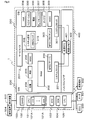
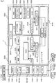
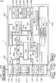
- FIG. 1 is a diagram schematically showing a configuration of a vehicle device as a functional block
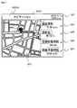
- FIG. 2 is a diagram schematically showing an example of a display screen
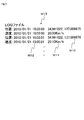
- FIG. 3 is a diagram schematically showing an example of the diagnostic information
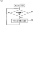
- FIG. 4 is a diagram showing the flow of setting the time at startup
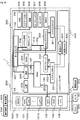
- FIG. 5 is a diagram schematically showing a time change mode based on GNSS.
- FIG. 6 is a diagram showing a flow of processing for changing the time in the application
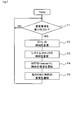
- FIG. 7 is a diagram showing a flow of processing for changing the time in TMM
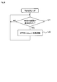
- FIG. 8 is a diagram showing a flow of processing for changing the time in the TMM thread
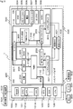
- FIG. 9 is a diagram schematically showing a time change mode based on a user operation
- FIG. 10 is a diagram schematically showing a time change mode based on connection with a mobile terminal
- FIG. 11 is a diagram schematically showing a time change mode based on the DCM.
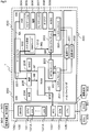
- the vehicular device 1 includes one CPU module 100 as a hardware module, and a plurality of operating systems, here, two operating systems, OS 200 and OS 300, operate on the CPU module 100. Is configured as a computerized environment.
- the operating system will be referred to as the OS.
- the OS 200 and the OS 300 operate on the hypervisor 400 at the same time.
- the CPU module 100 includes physical hardware such as a CPU 101, a Global Navigation Satellite System System 102 (hereinafter, GNSS module 102), a RealTimeClock 103 (hereinafter, RTC 103), a Data Communication Module 104 (hereinafter, DCM 104), and various interface groups 105. Etc. are provided.
- the hardware mounted on the CPU module 100 is not limited to these, and for example, a storage unit such as a memory storing a computer program is also mounted.
- the CPU 101 constitutes a main control unit of the vehicle device 1, and includes a plurality of cores 101A in this embodiment. Similar to a general virtualized environment, each core 101A is assigned with an appropriate number according to the processing capacity required by the OS 200 and the OS 300. The number and allocation of cores 101A are appropriately selected according to the required performance and the like.
- the GNSS module 102 receives a signal from an artificial satellite of the global positioning satellite system, and is used to specify a position and a time based on the received signal.
- the GNSS module 102 is provided with a module corresponding to a target method among various methods such as Global Positioning System, GLObal NAvigation Satellite System, Galileo, Quasi-Zenith Satellite System, and BeiDou Navigation Navigation Satellite System.
- RTC103 is a real-time clock and realizes a clock function.
- the RTC 103 holds a reference time in the vehicle device 1.
- the time stored in the RTC 103 is referred to as the basic time of the vehicle device 1 for convenience.
- the RTC 103 is connected to a backup battery (not shown), and keeps the time even when the vehicle device 1 is powered off.
- the RTC 103 stores Greenwich Mean Time.
- the DCM 104 is a data communication device for a vehicle, and communicates with a center provided outside the vehicle or with another Electronic Control Unit 50 (hereinafter, ECU 500) provided in the vehicle. To do.
- the DCM 104 sends vehicle information collected from the ECU 500 to a center via a network, receives information from the center and informs the user of the information, and automatically connects to the center in the event of an accident and automatically connects to the center. The location and time of occurrence are reported.
- the interface group 105 is composed of interfaces that perform various communications inside the vehicle.
- the interface group 105 includes a wired system, a wireless system, or both systems.
- the interface group 105 includes a CAN interface that communicates with the ECU 500 and the meter 501, a wired interface such as a USB that communicates with the portable terminal 502 owned by the user, and a short-range wireless interface. There is.
- the CPU module 100 is also connected to the display device 503.
- the display device 503 displays an operation menu of the vehicle device 1, a basic time, execution results of various applications, and the like.
- the number of display devices 503 is not limited to one, and a plurality of display devices 503 can be connected to the vehicle device 1.
- the CPU module 100 is connected to the operation device 504 to which a user operation is input.
- the operation device 504 is configured as an operation switch, a touch panel provided on the screen of the display device 503, or a combination thereof.
- the meter 501 may be configured by a liquid crystal panel, for example, and the CPU module 100 may be configured to perform image generation processing and display processing of a speedometer and a tachometer. That is, the number of display devices 503 connected to the vehicle device 1 is not limited to one, and a plurality of display devices 503 can be connected.
- the OS 200 and OS 300 will be described. Although various computer programs are executed on the OS 200 and OS 300, the computer programs executed by the OS 200 and OS 300 are referred to as applications in this embodiment for the sake of simplicity of description. However, when describing an application having a specific function, the application will also be referred to as a position application 204, a clock application 205, or the like, for example, as described later.
- a so-called real-time OS is adopted as the OS 200.
- the OS 200 is relatively excellent in real-time property as compared with the OS 300, and an application that requires a high processing speed is executed.
- the OS 200 operates based on the system clock 201 corresponding to the clock function. That is, the OS 200 has its own clock function that is not shared with the OS 300.
- the time stored in the system clock 201 is the basic time of the OS 200.
- a Time Management module 202 (hereinafter, TMM 202) as a synchronization part, a Network Time Protocol protocol daemon 203 (hereinafter, NTPD 203) that is a server side, a position application 204, a clock application 205, etc. are installed.
- TMM 202 a Time Management module 202
- NTPD 203 Network Time Protocol protocol daemon 203
- the applications installed on the OS 200 are not limited to these, and the Miscellaneous application 206 (hereinafter, MISC 206) required for the operation and control of the OS 200 and the vehicle device 1 is installed.
- MISC 206 Miscellaneous application 206
- the TMM 202 is a dedicated application that functions as a synchronization unit that synchronizes the time between the OS 200 and the OS 300. Although details will be described later, the TMM 202 reads the time from the RTC 103, rewrites the time held by the RTC 103, accepts a time change request from each application, and receives the change request, and then the other It has a function of notifying the time change to another OS 300 different from the OS 200 in which it operates.
- This TMM202 is installed in the OS200. Therefore, in the vehicle device 1, the time synchronization is performed in a mode in which the OS 200 is the master and the OS 300 is the slave. If three or more OSs are built on the CPU module 100, one of the OSs can be the master and the other OSs can be the slaves to build a similar environment.
- NTPD203 is an application that functions as a so-called Network Time Protocol server (hereinafter, NTP server).
- NTP server Network Time Protocol server
- the NTPD 203 provides the time held by itself in response to a request from the NTPD 303 on the client side provided on the OS 300 side. That is, in the vehicle device 1, time synchronization using NTP is performed.
- the location application 204 is an application that uses the GNSS module 102.
- the position application 204 has a function of specifying a current position and specifying an accurate time, for example. That is, the position application 204 is an application capable of acquiring time from outside the vehicle device 1. In other words, the position application 204 and other applications that can acquire the time to be described later can acquire the accurate time at which the basic time of the vehicular device 1 held in the RTC 103 can be changed or corrected to be accurate. It is an application.
- the position application 204 has a function of changing the time of the vehicle device 1 based on the specified time. However, as described later, in this embodiment, the time change by the position application 204 is configured to be performed via the TMM 202 in this embodiment.
- the clock application 205 is an application having a function of displaying the basic time, a function of accepting a time change from the user, and the like. That is, the clock application 205 is an application that can acquire the time from outside the vehicle device 1 and can set the time here. For example, as shown in FIG. 2, the clock application 205 displays the current time M1 on the screen 503A of the display device 503, such as January 1, 2010 at 10:00 am.
- the display mode of the current time and the like is not limited to the example shown in FIG. 2 and may be any display mode that can be recognized by the user.
- the clock application 205 also accepts a time change operation by the user.
- This changing operation includes, for example, an operation of adjusting the time in each country or region, and an operation of setting the time by the user himself/herself.
- the time change by the clock application 205 is configured to be performed via the TMM 202.
- the OS 200 is configured to be capable of various communications with the OS 300 by the service bus 207 realized by software.
- the OS 300 is a so-called general-purpose OS, and executes applications that do not require a relatively high processing speed as compared with the OS 200 and applications that require general-purpose processing such as images and moving images.
- the OS 300 operates based on the system clock 301 that realizes the clock function. That is, the OS 300 has its own clock function that is not shared with the OS 200.
- a system setting application 302 for example, a system setting application 302, a client side NTPD 303, an HMI application 304, a navigation application 305, a telephone application 306, a telematics application 307, a diagnosis application 308, etc. are installed.
- the applications installed on the OS 300 are not limited to these, and various MISC applications 309 necessary for the operation and control of the OS 300 and the vehicle device 1 are installed.
- the system setting application 302 is an application that makes various settings for the OS.
- the system setting application 302 includes an application for making various settings in the OS. Further, as one of the system setting applications 302, a TMM thread 310 that performs a process related to the change of the time in the OS is installed.
- the TMM thread 310 is an application that receives a notification from the TMM 202 of the OS 200. Although the details will be described later, the TMM thread 310 has a function of notifying the application such as the system clock 301 or the client side NTPD 303 of the change of the time notified from the TMM 202 by communicating with the TMM 202. There is.
- the time held by the system clock 301 is the basic time of the OS 300. It can be said that the TMM thread 310 is also a part of the program forming the synchronization unit.
- NTPD 303 is an application that functions as a so-called NTP client.
- the NTPD 303 acquires a reference time on the OS 300 side by communicating with the server-side NTPD 203 mounted on the OS 200 side.
- the HMI application 304 is an application that provides a human-machine interface.
- the HMI application 304 displays, for example, an operation menu of the vehicle device 1 and receives an operation input from the operation device 504. That is, the HMI application 304 is an application capable of acquiring the time from the outside of the vehicular device 1 by linking with the clock application 205 on the OS side, and setting by the user here.
- the navigation application 305 is an application that realizes so-called car navigation such as route guidance to a destination. For example, as shown in FIG. 2, when the destination is set, the navigation application 305 displays a destination mark M2, a route guidance screen M3, a current time M4, a route M5 to the destination, an estimated required time M6, or an estimated arrival time. Display M7, etc. Note that FIG. 2 is an example of the navigation screen, and the information to be displayed and the display format are not limited to this.
- the telephone application 306 is an application that enables the mobile terminal 502 owned by the user to be used from the vehicle device 1 side.
- the telephone application 306 performs processing for operating the vehicle device 1 and the mobile terminal 502 in cooperation with each other, such as acquisition of the time set in the mobile terminal 502, so-called hands-free call, and display of mail received by the mobile terminal 502. To do. That is, the telephone application 306 is an application that can acquire the time from outside the vehicle device 1.
- the processing performed by the telephone application 306 is not limited to these.
- the telematics application 307 is an application that collects vehicle information such as speed and position or vehicle shake, and acquires information including time from an external center. That is, the telematics application 307 is an application that can acquire the time from outside the vehicle device 1.
- the telematics application 307 performs processing such as analysis based on the collected vehicle information and notification to the center when a failure or accident occurs. However, the processing performed by the telematics application 307 is not limited to these.
- the diagnosis application 308 is an application that records a log of the vehicle device 1.
- the diagnosis application 308 performs a process of recording the collected vehicle information in time series, recording an event generated by the application, and the like.
- the processing performed by the diagnostic application 308 is not limited to these.
- the diagnostic application 308 attaches a time stamp M12 to the current position information M10 acquired on the OS200 side and the vehicle information M11 such as speed collected from another ECU 500 on the OS300 side. Then, it is recorded as a log M13.
- the vehicle was traveling at a position of 34.991022 degrees north latitude and 137.0009875 degrees east longitude at a speed of 20.00 km/h. Has been done.
- the log M13 illustrated in FIG. 3 is an example, and the information collected and recorded by the diagnostic application 308 and the recording mode thereof are not limited to this.
- the hypervisor 400 is an application that operates one or more OSs in a virtualized environment.
- the hypervisor 400 is realized by the function of the OS 200. Therefore, strictly speaking, the vehicle device 1 is configured such that the OS 200 operates on the CPU module 100 and the OS 300 operates on the hypervisor function of the OS 200.
- a virtual RTC 401 used when the OS 200 and OS 300 operate, and a virtual HIGH Precision Event Timer 402 (hereinafter, virtual HPET 402) that realizes a more detailed clock function than the virtual RTC 401 are installed.
- virtual HPET 402 virtual HIGH Precision Event Timer 402
- FIG. 1 Although not shown in FIG. 1, other virtual devices that virtualize various hardware are also mounted on the hypervisor 400. The number and types of virtual devices and OSs operating on the hypervisor 400 are not limited to these.
- the OS When the vehicle device 1 is powered on, the OS is first activated on the CPU module 100. It should be noted that in the present embodiment, since the hypervisor 400 is provided as a function of the OS 200 as described above, the OS 200 starts up first, but in the case of a general virtualized environment, the hypervisor 400 starts up first. Will be started.
- the TMM202 When the OS200 starts up, the TMM202 starts operating.
- the TMM 202 which has started the operation acquires the time from the RTC 103 as shown by an arrow 4A in FIG. Then, the TMM 202 sets the acquired time in the system clock 201 as indicated by an arrow 4B, and the NTPD 203 on the server side acquires the time from the system clock 201 as indicated by an arrow 4C. In this way, the basic time on the OS 200 side is set and held.
- the hypervisor 400 when the OS starts, the hypervisor 400 also starts operating. At this time, the time is set in the virtual RTC 401 and the virtual HPET 402. Then, when the OS 300 is activated on the hypervisor 400, the NTPD 303 on the client side accesses the NTPD 203 on the server side to acquire the time, as indicated by an arrow 4D. After that, as indicated by an arrow 4E, the acquired time is set in the system clock 301, and the basic time is set and held also in the OS 300 side.
- the OS 200 and the OS 300 have their respective basic times synchronized at the time of activation.
- the OS 200 operates based on the system clock 201
- the OS 300 operates based on the system clock 301.
- the current time M1 is a time based on the basic time held by the system clock 201 on the OS 200 side.
- the current time M4 displayed on the navigation screen is displayed based on the basic time held by the system clock 301 on the OS 300 side.
- the OS is There is a possibility that a time difference occurs between the OSs, that is, the time is not synchronized between the OSs.
- various problems may occur in the vehicle device 1. For example, in the example of FIG. 2, different times are displayed on one screen, which may confuse the user. Further, for example, in the example shown in FIG. 3, the time stamps of the position and the speed may be displaced, and a problem may occur during data analysis. Further, according to the NTP specifications, if a shift of 1000 msec or more occurs, it becomes impossible to synchronize the time using the NTP, and thus it may be impossible to synchronize the time between the OSs.
- the vehicle device 1 is configured to synchronize the time of each OS by the synchronization unit here, the TMM 202, which synchronizes the time of each OS.
- the TMM 202 which synchronizes the time of each OS.
- some factors that change the basic time of the vehicle device 1 and the operation of the TMM 202 with respect to the factors will be described.
- the operation of the application and the processing flow of the TMM 202 and the TMM thread 310 are basically the same, so for all the factors, the processing related to the time change is extracted. This will be described with reference to FIGS. 6 to 8.
- detailed description of the overlapping processing in each factor will be omitted.
- the GNSS can identify the current position and time using a signal emitted from an artificial satellite.
- the GNSS module 102 receives a signal, and the position application 204 specifies the current position and the time. At this time, the time used in the GNSS is very accurate, and therefore, if the specified time is set as the basic time, the basic time of the vehicular device 1 can be accurately maintained.
- the location application 204 is an application that runs on the OS 200. Therefore, even if the basic time of the OS 200 is changed by the position application 204, the change is completed in the OS 200 and is not reflected in the OS 300. Therefore, the position application 204 of the present embodiment is configured to notify the time to the TMM 202 when the time is specified, and entrust the TMM 202 to change the basic time.
- the position application 204 specifies the position and the time when it receives data from the GNSS module 102 as shown by an arrow 5A in FIG. Subsequently, the position application 204 determines whether to change the time in step S1 as shown in FIG.
- the position application 204 may be NO in step S1 and may determine not to change the time when, for example, only a short time has passed since the previous change.
- step S1 when the position application 204 determines to change the time, the result is YES in step S1 and the time is changed to the TMM 202 in step S2 so as to change to the specified time as shown by the arrow 5B in FIG. Notify the request.
- This change request is notified to the TMM 202 as data of the time to be changed or data capable of specifying the time to be changed.
- the TMM 202 determines in step T1 whether or not a change request from any application has been accepted, as shown in FIG.
- the determination in step T1 is NO, and the process proceeds to step T1 to wait for the change request.
- the process flow shown in FIG. 7 corresponds to the basic flow of the synchronization process.
- step T1 when the TMM 202 determines that the change request has been received, YES is obtained in step T1, and the time of the RTC 103 is changed in step T2 as indicated by an arrow 5C in FIG. Subsequently, the TMM 202 changes the time of the system clock 201 in step T3 as indicated by the arrow 5D in FIG. 5, and notifies the NTPD 203 of the time change in step T4 as indicated by the arrow 5E in FIG. To do. In this case, the TMM 202 may directly notify the NTPD 203 of the time change.
- the TMM 202 notifies the time change to the OS 300 via the service bus 207 in step T5 as shown by an arrow 5F in FIG. More specifically, the TMM 202 notifies the TMM thread 310 operating on another OS 300 of the change in time.
- the TMM thread 310 operating on the OS 300 side determines whether or not the time change is notified in step U1. If the TMM thread 310 determines that the time change has not been notified, the TMM thread 310 becomes NO in step U1 and moves to step U1 to wait for the notification.
- step U1 determines that it has received the change notification
- the determination result in step U1 is YES and the NTPD 303 on the client side is restarted in step U2 as indicated by an arrow 5G in FIG.
- the restarted NTPD 303 acquires the time from the NTPD 203 on the server side as shown by an arrow 5H in FIG. 5, and sets the acquired time as the system clock 301 as shown by an arrow 5I.
- the time synchronized with the OS 200 side is set and held in the system clock of the OS 300.
- the OS 200 side when the vehicle device 1 changes the basic time based on the GNSS, the OS 200 side, more strictly speaking, notifies the OS 300 side by the TMM 202 of the time change that occurs in the RTC 103. As a result, the time is synchronized between the OSs.
- the vehicle device 1 does not have the GNSS, the user cannot set the current time because the time cannot be specified by the GNSS. Further, even in the case of the configuration including the GNSS, it is assumed that some users intentionally advance the displayed time ahead of the accurate time so as not to be behind schedule. Therefore, the vehicle device 1 is equipped with a clock application 205 that performs a process of changing the basic time by a user operation.
- the clock application 205 is an application that runs on the OS 200. Therefore, even if the basic time is changed by the clock application 205, the change is completed in the OS 200 and is not reflected in the OS 300. Therefore, when the time is set, the clock application 205 of the present embodiment is configured to notify the TMM 202 of the time and entrust the TMM 202 to change the basic time.
- the time setting or changing operation is performed by the user, as shown by an arrow 9A in FIG. 9, from the HMI application 304 that receives an input of the operation device 504, via the service bus 207.
- the operation content is notified to the clock application 205.
- This operation content includes the time set by the user. That is, when the operation content is to change the time, the clock application 205 determines to change the time as shown in FIG. 6, the determination result in step S1 is YES, and as shown by an arrow 9B in FIG. In S2, the TMM 202 is notified of the time change request.
- step T1 When the TMM 202 determines that the change request has been accepted as shown in FIG. 7 as in the case of changing the basic time based on GNSS described above, YES is obtained in step T1 and the step shown by arrow 9C in FIG. 9 is performed.
- the time of the RTC 103 is changed at T2
- the time of the system clock 201 is changed at step T3 as indicated by arrow 9D
- the time change is notified to the NTPD 203 at step T4 as indicated by arrow 9E.
- the TMM 202 notifies the OS 300 of the time change via the service bus 207 in step T5.
- step U1 When the TMM thread 310 operating on the OS side determines that the notification of the change has been received as shown in FIG. 8, YES is obtained in step U1 and the NTPD 303 on the client side is shown in step U2 in step U2 as shown by an arrow 9G in FIG. To restart. Then, the restarted NTPD 303 acquires the time from the NTPD 203 on the server side as shown by an arrow 9H in FIG. 9, and sets the acquired time as the system clock 301 as shown by an arrow 9I. As a result, the time synchronized with the OS 200 side is set and held in the system clock of the OS 301.
- the OS 200 side when the vehicle device 1 changes the basic time based on the user's operation, the OS 200 side, more strictly speaking, notifies the OS 300 side of the time change occurring in the RTC 103 by the TMM 202. As a result, the time is synchronized between the OSs.
- the difference between the time set by the user and the basic time stored until then is stored as the offset time.
- the displayed time becomes the offset time added.
- an accurate time is set in the RTC 103. Therefore, the vehicle device 1 can operate at an accurate time while meeting the user's desire to advance the displayed time.
- the time set by the user is set as the basic time of the vehicle device 1.
- the basic time of the vehicular device 1 can be updated when the accurate time can be obtained by connecting to the mobile terminal 502 or the DCM 104 can obtain the accurate time.
- the offset time may be used.
- the vehicle device 1 can operate in cooperation with the mobile terminal 502 owned by the user as described above. Then, the portable terminal 502 is considered to hold the correct time via the communication line. In other words, if the time of the mobile terminal 502 is acquired, the basic time of the vehicular device 1 can be set to an accurate time. Therefore, the vehicle device 1 is equipped with a telephone application 306 that performs a process of changing the basic time of the vehicle device 1 based on the time stored in the connected portable terminal 502.
- the phone application 306 is an application that runs on the OS 300. Therefore, even if the basic time is changed by the telephone application 306, the change is completed in the OS 300 and is not reflected in the OS 200. Therefore, the telephone application 306 of this embodiment is configured to notify the TMM 202 of the time when it is connected to the mobile terminal 502 and specify the time, and entrusts the TMM 202 to change the basic time.
- the telephone application 306 acquires the time stored in the mobile terminal 502. Then, the telephone application 306 has determined that the time should be changed as shown in FIG. 6 because the correct time has been acquired, and YES is obtained in step S1 and the TMM 202 is obtained in step S2 as shown by an arrow 10A in FIG. Notify the time change request to.
- step T1 When the TMM 202 determines that the change request has been accepted as shown in FIG. 7 as in the case of changing the basic time based on GNSS described above, YES is obtained in step T1 and the step shown by arrow 10B in FIG.
- the time of the RTC 103 is changed at T2
- the time of the system clock 201 is changed at step T3 as indicated by arrow 10C
- the NTPD 203 is notified of the time change at step T4 as indicated by arrow 10D.
- the TMM 202 notifies the OS 300 of the time change via the service bus 207 in step T5, as indicated by an arrow 10E in FIG.
- step U1 YES is determined in step U1 and the NTPD 303 on the client side is determined in step U2 in step U2 as indicated by an arrow 10F in FIG.
- the restarted NTPD 303 acquires the time from the NTPD 203 on the server side as shown by an arrow 10G in FIG. 10, and sets the acquired time as the system clock 301 as shown by an arrow 10H.
- the time synchronized with the OS 200 side is set and held in the system clock 301 of the OS 300.
- the vehicle device 1 reflects the time change on the RTC 103 by notifying the OS 200 side by the TMM 202 of the time change that conventionally occurs only on the OS 300 side when connected to the mobile terminal 502. , The time synchronization between the OSs is realized.
- the vehicle device 1 includes the DCM 104 as described above.
- the DCM 104 is configured to be able to communicate with the center via a communication line, and can acquire the time from the center side. That is, it is considered that the vehicle device 1 can set the basic time to an accurate time based on the time acquired by the DCM 104. Therefore, the vehicle device 1 is equipped with a telematics application 307 that performs a process of changing the basic time of the vehicle device 1 based on the time acquired via the DCM 104.
- the telematics application 307 is an application that runs on the OS 300. Therefore, even if the basic time is changed by the telematics application 307, the change is completed in the OS 300 and is not reflected in the OS 200. Therefore, the telematics application 307 of the present embodiment is configured to notify the TMM 202 of the time when the time is specified, and entrust the TMM 202 to change the basic time.
- the telematics application 307 acquires the time via the DCM 104, the telematics application 307 determines that the time should be changed as shown in FIG. 6 because the accurate time can be acquired, and the result is YE in step S1. As shown by an arrow 11A in FIG. 11, the TMM 202 is notified of the time change request in step S2.
- step T1 When the TMM 202 determines that the change request has been received as shown in FIG. 7 as in the case of changing the basic time based on the GNSS described above, YES is obtained in step T1 and the step shown by arrow 11B in FIG. 11 is performed.
- the time of the RTC 103 is changed at T2
- the time of the system clock 201 is changed at step T3 as indicated by arrow 11C
- the NTPD 203 is notified of the time change at step T4 as indicated by arrow 11D.
- the TMM 202 notifies the OS 300 of the time change via the service bus 207 in step T5 as indicated by an arrow 11E in FIG.
- the TMM thread 310 operating on the O300S side determines that it has received the change notification as illustrated in FIG. 8, the determination is YES in step U1 and the NTPD 303 on the client side in step U2 in step U2 as illustrated by an arrow 11F in FIG. To restart. Then, the restarted NTPD 303 acquires the time from the NTPD 203 on the server side as shown by an arrow 11G in FIG. 11, and sets the acquired time as the system clock 301 as shown by an arrow 11H. As a result, the time synchronized with the OS 200 side is set and held in the system clock of the OS 300.
- the vehicular device 1 notifies the OS 200 side by the TMM 202 of the time change that conventionally occurs only on the OS 300 side, based on the time acquired via the DCM 104, thereby changing the time to the RTC 103. Reflection and time synchronization between the OSs are realized.
- the vehicle device 1 synchronizes the times of the plurality of OSs 200 and 300 operating on the CPU module 100 with the TMM 202 as a synchronization unit that synchronizes the times. Even when the time is changed by an application other than the application exemplified in the present embodiment, the time between the OSs can be similarly synchronized by using the TMM 202.
- the vehicular device 1 has a virtual environment in which a plurality of OSs such as OS 200 and OS 300 operate simultaneously on one CPU module 100.
- the OS 200 and the OS 300 OS operate based on their respective system clocks, that is, their own clock functions.
- the change made on a certain OS is completed within that OS and is not notified to other OSs. Therefore, even if the time is changed on one OS, the change is not reflected on the other OS, and there is a possibility that the time is not synchronized between the OSs.
- the vehicular apparatus 1 synchronizes the time of each OS by notifying the other OS of the time change performed in any OS by the TMM 202 corresponding to the synchronization unit.
- the vehicular device 1 is notified to other OSs of the time change performed on one of the OSs. Then, when the time change is notified, the OS on the notified side can change the time.
- a time synchronization method including a synchronization process for synchronizing the time of each OS by notifying the other OS of the change of the time performed on one of the OSs, or the control unit of the vehicle device 1, that is, the CPU module.
- the computer program that causes the 100 to execute the synchronization process can also synchronize the times between the plurality of OSs operating on the CPU module 100, and different times are displayed on one display device 503, which may confuse the user.
- the vehicle device 1 has a CPU module 100 on which an application for acquiring the time from outside the vehicle device 1 is installed. Then, the synchronization unit changes the time based on the time acquired by the application that acquires the time, and notifies each OS that the time has been changed. That is, each application entrusts the TMM 202 with the process of actually changing the time. As a result, it is possible to hold the accurate time and to ensure the notification to each OS when the time is changed.
- the application that acquires the time notifies the synchronization unit of the change request that requests the time change.
- the synchronization unit changes the time of the RTC 103 and notifies each OS that the time of the RTC 103 has been changed.
- the basic time of the vehicular device 1 can be changed based on the acquired accurate time, and the basic time of each OS is changed based on the accurate time. Therefore, the time can be synchronized in the entire vehicle device 1. Further, by delegating the process of actually changing the time to the TMM 202, in other words, by setting the change of the time of the RTC 103, which is the reference of the vehicular device 1, to the synchronizing unit, the time is changed.
- the notification to each OS can be made reliable.
- the TMM 202 as the synchronization unit is implemented as an application on any one OS. That is, since the synchronization unit is realized by software, it is not necessary to add additional hardware or change existing hardware. Therefore, it becomes easy to provide the synchronization unit in the vehicle device 1, and it is possible to easily provide the synchronization unit in the existing device.
- An application that receives a time change from the satellite positioning system such as the position application 204 of the embodiment, is installed in the vehicle device as an application that acquires the time from outside the vehicle device 1. Accordingly, if the accurate time is acquired based on the GNSS, the accurate time can be set as the basic time of each OS and the vehicle device 1. Therefore, the vehicle device 1 can be operated based on an accurate time.
- the vehicle device 1 is equipped with an application that receives a time change from the user, such as the clock application 205 of the embodiment, as an application that acquires the time from outside the vehicle device 1. Accordingly, the time desired by the user can be set as the basic time of the vehicular device 1. Therefore, the vehicle device 1 can be operated based on the time desired by the user.
- an application that receives a time change from the user such as the clock application 205 of the embodiment, as an application that acquires the time from outside the vehicle device 1. Accordingly, the time desired by the user can be set as the basic time of the vehicular device 1. Therefore, the vehicle device 1 can be operated based on the time desired by the user.
- the vehicle device 1 is equipped with an application that receives a time change from the portable terminal 502, as the telephone application 306 of the embodiment, as an application that acquires the time from outside the vehicle device 1. It is considered that the mobile terminal 502 acquires the accurate time via the communication line. Therefore, if a correct time is acquired by connecting to a mobile phone, the correct time can be set as the basic time of each OS and the vehicle device 1. Therefore, the vehicle device 1 can be operated based on an accurate time.
- the vehicle device 1 is equipped with an application that receives a time change from the DCM 104, as the telematics app 307 of the embodiment, as an application that acquires the time from the outside of the vehicle device 1. It is considered that the DCM 104 acquires the correct time via the communication line. Therefore, if the accurate time is acquired based on the DCM 104, the accurate time can be set as the basic time of each OS and the vehicle device 1. Therefore, the vehicle device 1 can be operated based on an accurate time.
- the vehicle device 1 is equipped with the NTPD 203 on the server side and the NTPD 303 on the client side, and synchronizes the time by NTP. As a result, it is possible to easily synchronize the time using the existing protocol, and it is possible to prevent a slight deviation in the time of each OS due to the time required for the notification.
- the time of each OS can be synchronized even if the time difference exceeds the NTP specification. ..
- the TMM 202 notifies the TMM thread 310 that the time has been changed has been described, but the TMM thread 310 or another OS may be notified of the changed time.
- the TMM 202 as the synchronization unit is mounted on the OS 200
- the TMM 202 may be mounted on the hypervisor 400. That is, the synchronization unit can be implemented as an application on the hypervisor 400 that operates each OS. With such a configuration, the time of each OS can be synchronized as in the above-described embodiment.
- the server-side NTPD 203 is installed in the OS 200, and the example in which the OS 200, that is, the OS running on the hypervisor 400, serves as a master when synchronizing the time is described.
- the server-side NTPD 203 is a hypervisor. It is also possible to adopt a configuration in which it is installed in 400, and the NTPD 303 on the client side is installed in each OS. That is, the hypervisor 400 can be configured to be a master when synchronizing the time. With such a configuration, the time of each OS can be synchronized as in the above-described embodiment.
- the hypervisor 400 is mounted by the function of the OS 200
- a general virtualization environment configuration in which the dedicated hypervisor 400 is mounted on the CPU module 100 and a plurality of OSs operate on the hypervisor 400
- the time can be synchronized between the OSs by the method and program shown in the embodiment.
- the TMM 202 and the NTPD 203 on the server side can be mounted on the OS as in the embodiment, or can be mounted on the hypervisor 400.
- the example in which the client-side NTPD 303 is restarted by the TMM thread 310 is shown, but it is also possible to notify the client-side NTPD 303 of re-acquisition of the time, and to restart when the re-acquisition is not possible. ..
- the configuration in which one CPU 101 is provided on one CPU module 100 has been illustrated, but a plurality of CPUs 101 are provided on one CPU module 100 and the hypervisor 400 operates on the plurality of CPUs 101. It can also be configured as a processor. That is, the configuration may be such that the synchronization unit is provided in one virtual environment built in one vehicle device 1. With such a configuration, the time of each OS can be synchronized as in the embodiment.
- control unit and the method described in the present disclosure are realized by a dedicated computer provided by configuring a processor and a memory programmed to execute one or a plurality of functions embodied by a computer program. May be done.
- control unit and the method thereof described in the present disclosure may be realized by a dedicated computer provided by configuring a processor with one or more dedicated hardware logic circuits.
- control unit and the method thereof described in the present disclosure are based on a combination of a processor and a memory programmed to execute one or more functions and a processor configured by one or more hardware logic circuits. It may be implemented by one or more dedicated computers configured.
- the computer program may be stored in a computer-readable non-transition tangible recording medium as an instruction executed by the computer.
Landscapes
- Engineering & Computer Science (AREA)
- Physics & Mathematics (AREA)
- General Physics & Mathematics (AREA)
- Theoretical Computer Science (AREA)
- Software Systems (AREA)
- Signal Processing (AREA)
- Computer Networks & Wireless Communication (AREA)
- General Engineering & Computer Science (AREA)
- Mechanical Engineering (AREA)
- Radar, Positioning & Navigation (AREA)
- Remote Sensing (AREA)
- Electric Clocks (AREA)
- Synchronisation In Digital Transmission Systems (AREA)
- Computer And Data Communications (AREA)
Priority Applications (1)
| Application Number | Priority Date | Filing Date | Title |
|---|---|---|---|
| US17/336,787 US12108311B2 (en) | 2019-02-01 | 2021-06-02 | Vehicular apparatus, and time synchronization method for vehicular apparatus |
Applications Claiming Priority (2)
| Application Number | Priority Date | Filing Date | Title |
|---|---|---|---|
| JP2019-017071 | 2019-02-01 | ||
| JP2019017071A JP7135903B2 (ja) | 2019-02-01 | 2019-02-01 | 車両用装置、車両用装置の時刻同期方法 |
Related Child Applications (1)
| Application Number | Title | Priority Date | Filing Date |
|---|---|---|---|
| US17/336,787 Continuation US12108311B2 (en) | 2019-02-01 | 2021-06-02 | Vehicular apparatus, and time synchronization method for vehicular apparatus |
Publications (1)
| Publication Number | Publication Date |
|---|---|
| WO2020158319A1 true WO2020158319A1 (ja) | 2020-08-06 |
Family
ID=71842046
Family Applications (1)
| Application Number | Title | Priority Date | Filing Date |
|---|---|---|---|
| PCT/JP2020/000300 Ceased WO2020158319A1 (ja) | 2019-02-01 | 2020-01-08 | 車両用装置、車両用装置の時刻同期方法 |
Country Status (3)
| Country | Link |
|---|---|
| US (1) | US12108311B2 (https=) |
| JP (1) | JP7135903B2 (https=) |
| WO (1) | WO2020158319A1 (https=) |
Cited By (1)
| Publication number | Priority date | Publication date | Assignee | Title |
|---|---|---|---|---|
| EP3852342A1 (en) * | 2020-01-20 | 2021-07-21 | Beijing Baidu Netcom Science And Technology Co., Ltd. | Automated and assisted parking based on in-vehicle operating systems |
Families Citing this family (6)
| Publication number | Priority date | Publication date | Assignee | Title |
|---|---|---|---|---|
| JP7625962B2 (ja) | 2021-04-30 | 2025-02-04 | 株式会社オートネットワーク技術研究所 | 車載装置、車載ネットワークシステムおよび情報処理方法 |
| DE102021207635A1 (de) | 2021-07-16 | 2023-01-19 | Siemens Mobility GmbH | Verfahren und Anordnung zur Zeitsynchronisation von Geräten eines Schienenfahrzeugs |
| JP2023077659A (ja) * | 2021-11-25 | 2023-06-06 | 日本特殊陶業株式会社 | 車両情報管理システム |
| CN114430303B (zh) * | 2022-01-25 | 2023-11-07 | 同济大学 | 一种用于车路协同的时间同步实现方法及实现系统 |
| US12325437B2 (en) * | 2022-04-29 | 2025-06-10 | Volvo Car Corporation | Method for synchronizing a clock-free computational node in a vehicle, method for performing an action at a pre-defined time, first computational node, second computational node and computational system for a vehicle |
| CN116679796A (zh) * | 2023-05-15 | 2023-09-01 | 国能朔黄铁路发展有限责任公司 | 时间同步方法、装置、存储介质和电子设备 |
Citations (7)
| Publication number | Priority date | Publication date | Assignee | Title |
|---|---|---|---|---|
| JP2006285875A (ja) * | 2005-04-04 | 2006-10-19 | Hitachi Ltd | 計算機システム、ログ収集方法、及びコンピュータプログラム |
| JP2014134989A (ja) * | 2013-01-11 | 2014-07-24 | Hitachi Ltd | 計算機システム及び計算機管理方法 |
| JP2014157386A (ja) * | 2013-02-14 | 2014-08-28 | Mitsubishi Electric Corp | データ処理システム |
| WO2015186220A1 (ja) * | 2014-06-05 | 2015-12-10 | 株式会社日立製作所 | ストレージ装置及びストレージ装置の動作解析方法 |
| WO2017061203A1 (ja) * | 2015-10-08 | 2017-04-13 | 株式会社デンソー | 無線通信装置、無線通信システム |
| JP2018044842A (ja) * | 2016-09-14 | 2018-03-22 | カシオ計算機株式会社 | 電子時計、電子時計の時刻変更方法、および、プログラム |
| JP2018112425A (ja) * | 2017-01-10 | 2018-07-19 | 株式会社デンソーテン | システム時刻同期方法 |
Family Cites Families (18)
| Publication number | Priority date | Publication date | Assignee | Title |
|---|---|---|---|---|
| US6792466B1 (en) * | 2000-05-09 | 2004-09-14 | Sun Microsystems, Inc. | Trusted construction of message endpoints in a distributed computing environment |
| CN101309168A (zh) * | 2000-07-31 | 2008-11-19 | 株式会社东芝 | 代理程序系统 |
| US8799478B2 (en) * | 2004-03-01 | 2014-08-05 | Avaya Inc. | Web services and session initiation protocol endpoint for converged communication over internet protocol networks |
| JP2007170867A (ja) | 2005-12-19 | 2007-07-05 | Calsonic Kansei Corp | 自動車内時計の同期システム |
| US20090182805A1 (en) * | 2008-01-15 | 2009-07-16 | Vishnu-Kumar Shivaji-Rao | Methods and Systems for Peripheral-Device-Assisted Networking |
| US8265042B1 (en) * | 2009-03-02 | 2012-09-11 | Sprint Communications Company L.P. | Ethernet backhaul architecture |
| US8135866B2 (en) * | 2010-01-22 | 2012-03-13 | Research In Motion Limited | System and method for detecting and processing stale messages |
| US8666643B2 (en) * | 2010-02-01 | 2014-03-04 | Miovision Technologies Incorporated | System and method for modeling and optimizing the performance of transportation networks |
| JP2012113504A (ja) | 2010-11-24 | 2012-06-14 | Seiko Precision Inc | 通信端末、該通信端末の制御方法、及びプログラム |
| US8959514B2 (en) * | 2012-11-06 | 2015-02-17 | Red Hat Israel, Ltd. | Virtual machine monitor display split using multiple client devices in a virtualization system |
| US9819593B1 (en) * | 2013-01-22 | 2017-11-14 | Hypori, Inc. | System, method and computer program product providing bypass mechanisms for a virtual mobile device platform |
| US9852147B2 (en) * | 2015-04-01 | 2017-12-26 | Dropbox, Inc. | Selective synchronization and distributed content item block caching for multi-premises hosting of digital content items |
| US10425477B2 (en) * | 2015-09-15 | 2019-09-24 | Microsoft Technology Licensing, Llc | Synchronizing file data between computer systems |
| US10691718B2 (en) * | 2015-10-29 | 2020-06-23 | Dropbox, Inc. | Synchronization protocol for multi-premises hosting of digital content items |
| WO2018067817A1 (en) * | 2016-10-05 | 2018-04-12 | Convida Wireless, Llc | Service layer time synchronization |
| US10593198B2 (en) * | 2016-12-06 | 2020-03-17 | Flir Commercial Systems, Inc. | Infrastructure to vehicle communication protocol |
| US10355799B2 (en) * | 2017-09-28 | 2019-07-16 | Ciena Corporation | Pseudowire clock recovery |
| JP7574629B2 (ja) * | 2020-12-03 | 2024-10-29 | 株式会社デンソー | 情報送信方法及び通信装置 |
-
2019
- 2019-02-01 JP JP2019017071A patent/JP7135903B2/ja active Active
-
2020
- 2020-01-08 WO PCT/JP2020/000300 patent/WO2020158319A1/ja not_active Ceased
-
2021
- 2021-06-02 US US17/336,787 patent/US12108311B2/en active Active
Patent Citations (7)
| Publication number | Priority date | Publication date | Assignee | Title |
|---|---|---|---|---|
| JP2006285875A (ja) * | 2005-04-04 | 2006-10-19 | Hitachi Ltd | 計算機システム、ログ収集方法、及びコンピュータプログラム |
| JP2014134989A (ja) * | 2013-01-11 | 2014-07-24 | Hitachi Ltd | 計算機システム及び計算機管理方法 |
| JP2014157386A (ja) * | 2013-02-14 | 2014-08-28 | Mitsubishi Electric Corp | データ処理システム |
| WO2015186220A1 (ja) * | 2014-06-05 | 2015-12-10 | 株式会社日立製作所 | ストレージ装置及びストレージ装置の動作解析方法 |
| WO2017061203A1 (ja) * | 2015-10-08 | 2017-04-13 | 株式会社デンソー | 無線通信装置、無線通信システム |
| JP2018044842A (ja) * | 2016-09-14 | 2018-03-22 | カシオ計算機株式会社 | 電子時計、電子時計の時刻変更方法、および、プログラム |
| JP2018112425A (ja) * | 2017-01-10 | 2018-07-19 | 株式会社デンソーテン | システム時刻同期方法 |
Cited By (2)
| Publication number | Priority date | Publication date | Assignee | Title |
|---|---|---|---|---|
| EP3852342A1 (en) * | 2020-01-20 | 2021-07-21 | Beijing Baidu Netcom Science And Technology Co., Ltd. | Automated and assisted parking based on in-vehicle operating systems |
| US11584363B2 (en) | 2020-01-20 | 2023-02-21 | Apollo Intelligent Driving Technology (Beijing) Co., Ltd. | Method, system, and apparatus for processing parking, and vehicle controller |
Also Published As
| Publication number | Publication date |
|---|---|
| JP2020126317A (ja) | 2020-08-20 |
| JP7135903B2 (ja) | 2022-09-13 |
| US20210289328A1 (en) | 2021-09-16 |
| US12108311B2 (en) | 2024-10-01 |
Similar Documents
| Publication | Publication Date | Title |
|---|---|---|
| US12108311B2 (en) | Vehicular apparatus, and time synchronization method for vehicular apparatus | |
| JP7263440B2 (ja) | 車両の時間同期方法、装置、機器、及び記憶媒体 | |
| JP6838222B2 (ja) | 車両制御装置、及び車両システム | |
| EP3779713B1 (en) | Processing device | |
| JP2024541174A (ja) | 車載オペレーティングシステム、デバッグシステム及び方法、電子機器及び記憶媒体 | |
| CN110569210B (zh) | 车载终端的主从结构及其方法 | |
| US10673808B2 (en) | Method and device for bus addressing, and method and device for providing information | |
| US20250321774A1 (en) | Signal processing device in vehicle and vehicle communication device including the same | |
| CN116318512B (zh) | 车辆时间授时方法、装置、车辆及存储介质 | |
| WO2022163315A1 (ja) | 車両用装置 | |
| US11336714B1 (en) | Queue-based distributed timer | |
| CN115250159A (zh) | 时间同步方法、装置、电子设备、存储介质及程序产品 | |
| CN116707692A (zh) | 多时间域时钟处理方法、装置、设备及存储介质 | |
| JP2022114164A (ja) | 車両用装置、車両用システム、外部装置 | |
| CN113810494B (zh) | 音频播放控制方法、装置、终端及存储介质 | |
| US20130027740A1 (en) | Identifying newly connected printers | |
| US20250311017A1 (en) | In-vehicle device, information processing method, and information processing program | |
| US12468656B2 (en) | Signal processing device and vehicle communication device including the same | |
| CN121750132A (zh) | 车辆时间同步方法、装置、存储介质以及车辆 | |
| CN117970996A (zh) | 域控制器的时间同步方法和装置、存储介质 | |
| EP4506815A1 (en) | Signal processing device and vehicle display device including same | |
| CN119283792A (zh) | 数据交互方法、装置、车辆控制器及车辆 | |
| CN121664346A (zh) | 一种授时方法和车辆 | |
| CN120890444A (zh) | 应用于辅助驾驶的数据处理方法、装置、设备及存储介质 | |
| CN118796752A (zh) | 核间通信方法、装置、芯片及电子设备 |
Legal Events
| Date | Code | Title | Description |
|---|---|---|---|
| 121 | Ep: the epo has been informed by wipo that ep was designated in this application |
Ref document number: 20749443 Country of ref document: EP Kind code of ref document: A1 |
|
| NENP | Non-entry into the national phase |
Ref country code: DE |
|
| 122 | Ep: pct application non-entry in european phase |
Ref document number: 20749443 Country of ref document: EP Kind code of ref document: A1 |