WO2020158319A1 - Vehicular device, and time synchronization method for vehicular device - Google Patents
Vehicular device, and time synchronization method for vehicular device Download PDFInfo
- Publication number
- WO2020158319A1 WO2020158319A1 PCT/JP2020/000300 JP2020000300W WO2020158319A1 WO 2020158319 A1 WO2020158319 A1 WO 2020158319A1 JP 2020000300 W JP2020000300 W JP 2020000300W WO 2020158319 A1 WO2020158319 A1 WO 2020158319A1
- Authority
- WO
- WIPO (PCT)
- Prior art keywords
- time
- application
- vehicle device
- change
- tmm
- Prior art date
Links
Images
Classifications
-
- H—ELECTRICITY
- H04—ELECTRIC COMMUNICATION TECHNIQUE
- H04W—WIRELESS COMMUNICATION NETWORKS
- H04W56/00—Synchronisation arrangements
- H04W56/001—Synchronization between nodes
- H04W56/002—Mutual synchronization
-
- B—PERFORMING OPERATIONS; TRANSPORTING
- B60—VEHICLES IN GENERAL
- B60R—VEHICLES, VEHICLE FITTINGS, OR VEHICLE PARTS, NOT OTHERWISE PROVIDED FOR
- B60R16/00—Electric or fluid circuits specially adapted for vehicles and not otherwise provided for; Arrangement of elements of electric or fluid circuits specially adapted for vehicles and not otherwise provided for
- B60R16/02—Electric or fluid circuits specially adapted for vehicles and not otherwise provided for; Arrangement of elements of electric or fluid circuits specially adapted for vehicles and not otherwise provided for electric constitutive elements
- B60R16/023—Electric or fluid circuits specially adapted for vehicles and not otherwise provided for; Arrangement of elements of electric or fluid circuits specially adapted for vehicles and not otherwise provided for electric constitutive elements for transmission of signals between vehicle parts or subsystems
-
- G—PHYSICS
- G04—HOROLOGY
- G04G—ELECTRONIC TIME-PIECES
- G04G21/00—Input or output devices integrated in time-pieces
- G04G21/04—Input or output devices integrated in time-pieces using radio waves
-
- G—PHYSICS
- G04—HOROLOGY
- G04G—ELECTRONIC TIME-PIECES
- G04G5/00—Setting, i.e. correcting or changing, the time-indication
-
- G—PHYSICS
- G04—HOROLOGY
- G04R—RADIO-CONTROLLED TIME-PIECES
- G04R20/00—Setting the time according to the time information carried or implied by the radio signal
- G04R20/02—Setting the time according to the time information carried or implied by the radio signal the radio signal being sent by a satellite, e.g. GPS
-
- G—PHYSICS
- G04—HOROLOGY
- G04R—RADIO-CONTROLLED TIME-PIECES
- G04R20/00—Setting the time according to the time information carried or implied by the radio signal
- G04R20/26—Setting the time according to the time information carried or implied by the radio signal the radio signal being a near-field communication signal
-
- G—PHYSICS
- G06—COMPUTING; CALCULATING OR COUNTING
- G06F—ELECTRIC DIGITAL DATA PROCESSING
- G06F1/00—Details not covered by groups G06F3/00 - G06F13/00 and G06F21/00
- G06F1/04—Generating or distributing clock signals or signals derived directly therefrom
- G06F1/10—Distribution of clock signals, e.g. skew
-
- G—PHYSICS
- G06—COMPUTING; CALCULATING OR COUNTING
- G06F—ELECTRIC DIGITAL DATA PROCESSING
- G06F9/00—Arrangements for program control, e.g. control units
- G06F9/06—Arrangements for program control, e.g. control units using stored programs, i.e. using an internal store of processing equipment to receive or retain programs
- G06F9/44—Arrangements for executing specific programs
- G06F9/455—Emulation; Interpretation; Software simulation, e.g. virtualisation or emulation of application or operating system execution engines
- G06F9/45533—Hypervisors; Virtual machine monitors
- G06F9/45558—Hypervisor-specific management and integration aspects
-
- H—ELECTRICITY
- H04—ELECTRIC COMMUNICATION TECHNIQUE
- H04W—WIRELESS COMMUNICATION NETWORKS
- H04W4/00—Services specially adapted for wireless communication networks; Facilities therefor
- H04W4/30—Services specially adapted for particular environments, situations or purposes
- H04W4/40—Services specially adapted for particular environments, situations or purposes for vehicles, e.g. vehicle-to-pedestrians [V2P]
-
- G—PHYSICS
- G06—COMPUTING; CALCULATING OR COUNTING
- G06F—ELECTRIC DIGITAL DATA PROCESSING
- G06F9/00—Arrangements for program control, e.g. control units
- G06F9/06—Arrangements for program control, e.g. control units using stored programs, i.e. using an internal store of processing equipment to receive or retain programs
- G06F9/44—Arrangements for executing specific programs
- G06F9/455—Emulation; Interpretation; Software simulation, e.g. virtualisation or emulation of application or operating system execution engines
- G06F9/45533—Hypervisors; Virtual machine monitors
- G06F9/45558—Hypervisor-specific management and integration aspects
- G06F2009/45595—Network integration; Enabling network access in virtual machine instances
Definitions
- the present disclosure relates to a vehicle device and a time synchronization method for the vehicle device.
- Patent Document 1 discloses that an accurate time is maintained by synchronizing with an external network time protocol server.
- the network time protocol is also referred to as NTP.
- the operating system is also referred to as the OS.
- an application that requires real-time processing, an application that displays an image, or the like is assigned to each OS in accordance with the required processing speed and characteristics to operate.
- Each OS has its own clock function, and each application operates using the clock function of the OS in which it is installed.
- the object of the present disclosure has been made in view of the above circumstances, and when operating a plurality of OSs on one CPU module at the same time, a vehicle device and a vehicle device that can synchronize the time of each OS.
- An object is to provide a time synchronization method for a device.
- the vehicular device of the present disclosure operates a plurality of operating systems simultaneously on one hardware module, and each operating system operates based on its own clock function.
- the system includes a synchronization unit that notifies each operating system of a time change made on the system and synchronizes the time of each operating system. With such a configuration, the time of each operating system can be synchronized.
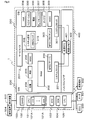
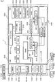
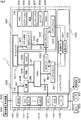
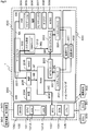
- FIG. 1 is a diagram schematically showing a configuration of a vehicle device as a functional block
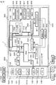
- FIG. 2 is a diagram schematically showing an example of a display screen
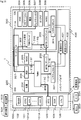
- FIG. 3 is a diagram schematically showing an example of the diagnostic information
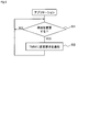
- FIG. 4 is a diagram showing the flow of setting the time at startup
- FIG. 5 is a diagram schematically showing a time change mode based on GNSS.
- FIG. 6 is a diagram showing a flow of processing for changing the time in the application
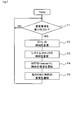
- FIG. 7 is a diagram showing a flow of processing for changing the time in TMM
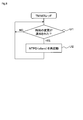
- FIG. 8 is a diagram showing a flow of processing for changing the time in the TMM thread
- FIG. 9 is a diagram schematically showing a time change mode based on a user operation
- FIG. 10 is a diagram schematically showing a time change mode based on connection with a mobile terminal
- FIG. 11 is a diagram schematically showing a time change mode based on the DCM.
- the vehicular device 1 includes one CPU module 100 as a hardware module, and a plurality of operating systems, here, two operating systems, OS 200 and OS 300, operate on the CPU module 100. Is configured as a computerized environment.
- the operating system will be referred to as the OS.
- the OS 200 and the OS 300 operate on the hypervisor 400 at the same time.
- the CPU module 100 includes physical hardware such as a CPU 101, a Global Navigation Satellite System System 102 (hereinafter, GNSS module 102), a RealTimeClock 103 (hereinafter, RTC 103), a Data Communication Module 104 (hereinafter, DCM 104), and various interface groups 105. Etc. are provided.
- the hardware mounted on the CPU module 100 is not limited to these, and for example, a storage unit such as a memory storing a computer program is also mounted.
- the CPU 101 constitutes a main control unit of the vehicle device 1, and includes a plurality of cores 101A in this embodiment. Similar to a general virtualized environment, each core 101A is assigned with an appropriate number according to the processing capacity required by the OS 200 and the OS 300. The number and allocation of cores 101A are appropriately selected according to the required performance and the like.
- the GNSS module 102 receives a signal from an artificial satellite of the global positioning satellite system, and is used to specify a position and a time based on the received signal.
- the GNSS module 102 is provided with a module corresponding to a target method among various methods such as Global Positioning System, GLObal NAvigation Satellite System, Galileo, Quasi-Zenith Satellite System, and BeiDou Navigation Navigation Satellite System.
- RTC103 is a real-time clock and realizes a clock function.
- the RTC 103 holds a reference time in the vehicle device 1.
- the time stored in the RTC 103 is referred to as the basic time of the vehicle device 1 for convenience.
- the RTC 103 is connected to a backup battery (not shown), and keeps the time even when the vehicle device 1 is powered off.
- the RTC 103 stores Greenwich Mean Time.
- the DCM 104 is a data communication device for a vehicle, and communicates with a center provided outside the vehicle or with another Electronic Control Unit 50 (hereinafter, ECU 500) provided in the vehicle. To do.
- the DCM 104 sends vehicle information collected from the ECU 500 to a center via a network, receives information from the center and informs the user of the information, and automatically connects to the center in the event of an accident and automatically connects to the center. The location and time of occurrence are reported.
- the interface group 105 is composed of interfaces that perform various communications inside the vehicle.
- the interface group 105 includes a wired system, a wireless system, or both systems.
- the interface group 105 includes a CAN interface that communicates with the ECU 500 and the meter 501, a wired interface such as a USB that communicates with the portable terminal 502 owned by the user, and a short-range wireless interface. There is.
- the CPU module 100 is also connected to the display device 503.
- the display device 503 displays an operation menu of the vehicle device 1, a basic time, execution results of various applications, and the like.
- the number of display devices 503 is not limited to one, and a plurality of display devices 503 can be connected to the vehicle device 1.
- the CPU module 100 is connected to the operation device 504 to which a user operation is input.
- the operation device 504 is configured as an operation switch, a touch panel provided on the screen of the display device 503, or a combination thereof.
- the meter 501 may be configured by a liquid crystal panel, for example, and the CPU module 100 may be configured to perform image generation processing and display processing of a speedometer and a tachometer. That is, the number of display devices 503 connected to the vehicle device 1 is not limited to one, and a plurality of display devices 503 can be connected.
- the OS 200 and OS 300 will be described. Although various computer programs are executed on the OS 200 and OS 300, the computer programs executed by the OS 200 and OS 300 are referred to as applications in this embodiment for the sake of simplicity of description. However, when describing an application having a specific function, the application will also be referred to as a position application 204, a clock application 205, or the like, for example, as described later.
- a so-called real-time OS is adopted as the OS 200.
- the OS 200 is relatively excellent in real-time property as compared with the OS 300, and an application that requires a high processing speed is executed.
- the OS 200 operates based on the system clock 201 corresponding to the clock function. That is, the OS 200 has its own clock function that is not shared with the OS 300.
- the time stored in the system clock 201 is the basic time of the OS 200.
- a Time Management module 202 (hereinafter, TMM 202) as a synchronization part, a Network Time Protocol protocol daemon 203 (hereinafter, NTPD 203) that is a server side, a position application 204, a clock application 205, etc. are installed.
- TMM 202 a Time Management module 202
- NTPD 203 Network Time Protocol protocol daemon 203
- the applications installed on the OS 200 are not limited to these, and the Miscellaneous application 206 (hereinafter, MISC 206) required for the operation and control of the OS 200 and the vehicle device 1 is installed.
- MISC 206 Miscellaneous application 206
- the TMM 202 is a dedicated application that functions as a synchronization unit that synchronizes the time between the OS 200 and the OS 300. Although details will be described later, the TMM 202 reads the time from the RTC 103, rewrites the time held by the RTC 103, accepts a time change request from each application, and receives the change request, and then the other It has a function of notifying the time change to another OS 300 different from the OS 200 in which it operates.
- This TMM202 is installed in the OS200. Therefore, in the vehicle device 1, the time synchronization is performed in a mode in which the OS 200 is the master and the OS 300 is the slave. If three or more OSs are built on the CPU module 100, one of the OSs can be the master and the other OSs can be the slaves to build a similar environment.
- NTPD203 is an application that functions as a so-called Network Time Protocol server (hereinafter, NTP server).
- NTP server Network Time Protocol server
- the NTPD 203 provides the time held by itself in response to a request from the NTPD 303 on the client side provided on the OS 300 side. That is, in the vehicle device 1, time synchronization using NTP is performed.
- the location application 204 is an application that uses the GNSS module 102.
- the position application 204 has a function of specifying a current position and specifying an accurate time, for example. That is, the position application 204 is an application capable of acquiring time from outside the vehicle device 1. In other words, the position application 204 and other applications that can acquire the time to be described later can acquire the accurate time at which the basic time of the vehicular device 1 held in the RTC 103 can be changed or corrected to be accurate. It is an application.
- the position application 204 has a function of changing the time of the vehicle device 1 based on the specified time. However, as described later, in this embodiment, the time change by the position application 204 is configured to be performed via the TMM 202 in this embodiment.
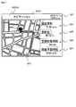
- the clock application 205 is an application having a function of displaying the basic time, a function of accepting a time change from the user, and the like. That is, the clock application 205 is an application that can acquire the time from outside the vehicle device 1 and can set the time here. For example, as shown in FIG. 2, the clock application 205 displays the current time M1 on the screen 503A of the display device 503, such as January 1, 2010 at 10:00 am.
- the display mode of the current time and the like is not limited to the example shown in FIG. 2 and may be any display mode that can be recognized by the user.
- the clock application 205 also accepts a time change operation by the user.
- This changing operation includes, for example, an operation of adjusting the time in each country or region, and an operation of setting the time by the user himself/herself.
- the time change by the clock application 205 is configured to be performed via the TMM 202.
- the OS 200 is configured to be capable of various communications with the OS 300 by the service bus 207 realized by software.
- the OS 300 is a so-called general-purpose OS, and executes applications that do not require a relatively high processing speed as compared with the OS 200 and applications that require general-purpose processing such as images and moving images.
- the OS 300 operates based on the system clock 301 that realizes the clock function. That is, the OS 300 has its own clock function that is not shared with the OS 200.
- a system setting application 302 for example, a system setting application 302, a client side NTPD 303, an HMI application 304, a navigation application 305, a telephone application 306, a telematics application 307, a diagnosis application 308, etc. are installed.
- the applications installed on the OS 300 are not limited to these, and various MISC applications 309 necessary for the operation and control of the OS 300 and the vehicle device 1 are installed.
- the system setting application 302 is an application that makes various settings for the OS.
- the system setting application 302 includes an application for making various settings in the OS. Further, as one of the system setting applications 302, a TMM thread 310 that performs a process related to the change of the time in the OS is installed.
- the TMM thread 310 is an application that receives a notification from the TMM 202 of the OS 200. Although the details will be described later, the TMM thread 310 has a function of notifying the application such as the system clock 301 or the client side NTPD 303 of the change of the time notified from the TMM 202 by communicating with the TMM 202. There is.
- the time held by the system clock 301 is the basic time of the OS 300. It can be said that the TMM thread 310 is also a part of the program forming the synchronization unit.
- NTPD 303 is an application that functions as a so-called NTP client.
- the NTPD 303 acquires a reference time on the OS 300 side by communicating with the server-side NTPD 203 mounted on the OS 200 side.
- the HMI application 304 is an application that provides a human-machine interface.
- the HMI application 304 displays, for example, an operation menu of the vehicle device 1 and receives an operation input from the operation device 504. That is, the HMI application 304 is an application capable of acquiring the time from the outside of the vehicular device 1 by linking with the clock application 205 on the OS side, and setting by the user here.
- the navigation application 305 is an application that realizes so-called car navigation such as route guidance to a destination. For example, as shown in FIG. 2, when the destination is set, the navigation application 305 displays a destination mark M2, a route guidance screen M3, a current time M4, a route M5 to the destination, an estimated required time M6, or an estimated arrival time. Display M7, etc. Note that FIG. 2 is an example of the navigation screen, and the information to be displayed and the display format are not limited to this.
- the telephone application 306 is an application that enables the mobile terminal 502 owned by the user to be used from the vehicle device 1 side.
- the telephone application 306 performs processing for operating the vehicle device 1 and the mobile terminal 502 in cooperation with each other, such as acquisition of the time set in the mobile terminal 502, so-called hands-free call, and display of mail received by the mobile terminal 502. To do. That is, the telephone application 306 is an application that can acquire the time from outside the vehicle device 1.
- the processing performed by the telephone application 306 is not limited to these.
- the telematics application 307 is an application that collects vehicle information such as speed and position or vehicle shake, and acquires information including time from an external center. That is, the telematics application 307 is an application that can acquire the time from outside the vehicle device 1.
- the telematics application 307 performs processing such as analysis based on the collected vehicle information and notification to the center when a failure or accident occurs. However, the processing performed by the telematics application 307 is not limited to these.
- the diagnosis application 308 is an application that records a log of the vehicle device 1.
- the diagnosis application 308 performs a process of recording the collected vehicle information in time series, recording an event generated by the application, and the like.
- the processing performed by the diagnostic application 308 is not limited to these.
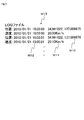
- the diagnostic application 308 attaches a time stamp M12 to the current position information M10 acquired on the OS200 side and the vehicle information M11 such as speed collected from another ECU 500 on the OS300 side. Then, it is recorded as a log M13.
- the vehicle was traveling at a position of 34.991022 degrees north latitude and 137.0009875 degrees east longitude at a speed of 20.00 km/h. Has been done.
- the log M13 illustrated in FIG. 3 is an example, and the information collected and recorded by the diagnostic application 308 and the recording mode thereof are not limited to this.
- the hypervisor 400 is an application that operates one or more OSs in a virtualized environment.
- the hypervisor 400 is realized by the function of the OS 200. Therefore, strictly speaking, the vehicle device 1 is configured such that the OS 200 operates on the CPU module 100 and the OS 300 operates on the hypervisor function of the OS 200.
- a virtual RTC 401 used when the OS 200 and OS 300 operate, and a virtual HIGH Precision Event Timer 402 (hereinafter, virtual HPET 402) that realizes a more detailed clock function than the virtual RTC 401 are installed.
- virtual HPET 402 virtual HIGH Precision Event Timer 402
- FIG. 1 Although not shown in FIG. 1, other virtual devices that virtualize various hardware are also mounted on the hypervisor 400. The number and types of virtual devices and OSs operating on the hypervisor 400 are not limited to these.
- the OS When the vehicle device 1 is powered on, the OS is first activated on the CPU module 100. It should be noted that in the present embodiment, since the hypervisor 400 is provided as a function of the OS 200 as described above, the OS 200 starts up first, but in the case of a general virtualized environment, the hypervisor 400 starts up first. Will be started.
- the TMM202 When the OS200 starts up, the TMM202 starts operating.
- the TMM 202 which has started the operation acquires the time from the RTC 103 as shown by an arrow 4A in FIG. Then, the TMM 202 sets the acquired time in the system clock 201 as indicated by an arrow 4B, and the NTPD 203 on the server side acquires the time from the system clock 201 as indicated by an arrow 4C. In this way, the basic time on the OS 200 side is set and held.
- the hypervisor 400 when the OS starts, the hypervisor 400 also starts operating. At this time, the time is set in the virtual RTC 401 and the virtual HPET 402. Then, when the OS 300 is activated on the hypervisor 400, the NTPD 303 on the client side accesses the NTPD 203 on the server side to acquire the time, as indicated by an arrow 4D. After that, as indicated by an arrow 4E, the acquired time is set in the system clock 301, and the basic time is set and held also in the OS 300 side.
- the OS 200 and the OS 300 have their respective basic times synchronized at the time of activation.
- the OS 200 operates based on the system clock 201
- the OS 300 operates based on the system clock 301.
- the current time M1 is a time based on the basic time held by the system clock 201 on the OS 200 side.
- the current time M4 displayed on the navigation screen is displayed based on the basic time held by the system clock 301 on the OS 300 side.
- the OS is There is a possibility that a time difference occurs between the OSs, that is, the time is not synchronized between the OSs.
- various problems may occur in the vehicle device 1. For example, in the example of FIG. 2, different times are displayed on one screen, which may confuse the user. Further, for example, in the example shown in FIG. 3, the time stamps of the position and the speed may be displaced, and a problem may occur during data analysis. Further, according to the NTP specifications, if a shift of 1000 msec or more occurs, it becomes impossible to synchronize the time using the NTP, and thus it may be impossible to synchronize the time between the OSs.
- the vehicle device 1 is configured to synchronize the time of each OS by the synchronization unit here, the TMM 202, which synchronizes the time of each OS.
- the TMM 202 which synchronizes the time of each OS.
- some factors that change the basic time of the vehicle device 1 and the operation of the TMM 202 with respect to the factors will be described.
- the operation of the application and the processing flow of the TMM 202 and the TMM thread 310 are basically the same, so for all the factors, the processing related to the time change is extracted. This will be described with reference to FIGS. 6 to 8.
- detailed description of the overlapping processing in each factor will be omitted.
- the GNSS can identify the current position and time using a signal emitted from an artificial satellite.
- the GNSS module 102 receives a signal, and the position application 204 specifies the current position and the time. At this time, the time used in the GNSS is very accurate, and therefore, if the specified time is set as the basic time, the basic time of the vehicular device 1 can be accurately maintained.
- the location application 204 is an application that runs on the OS 200. Therefore, even if the basic time of the OS 200 is changed by the position application 204, the change is completed in the OS 200 and is not reflected in the OS 300. Therefore, the position application 204 of the present embodiment is configured to notify the time to the TMM 202 when the time is specified, and entrust the TMM 202 to change the basic time.
- the position application 204 specifies the position and the time when it receives data from the GNSS module 102 as shown by an arrow 5A in FIG. Subsequently, the position application 204 determines whether to change the time in step S1 as shown in FIG.
- the position application 204 may be NO in step S1 and may determine not to change the time when, for example, only a short time has passed since the previous change.
- step S1 when the position application 204 determines to change the time, the result is YES in step S1 and the time is changed to the TMM 202 in step S2 so as to change to the specified time as shown by the arrow 5B in FIG. Notify the request.
- This change request is notified to the TMM 202 as data of the time to be changed or data capable of specifying the time to be changed.
- the TMM 202 determines in step T1 whether or not a change request from any application has been accepted, as shown in FIG.
- the determination in step T1 is NO, and the process proceeds to step T1 to wait for the change request.
- the process flow shown in FIG. 7 corresponds to the basic flow of the synchronization process.
- step T1 when the TMM 202 determines that the change request has been received, YES is obtained in step T1, and the time of the RTC 103 is changed in step T2 as indicated by an arrow 5C in FIG. Subsequently, the TMM 202 changes the time of the system clock 201 in step T3 as indicated by the arrow 5D in FIG. 5, and notifies the NTPD 203 of the time change in step T4 as indicated by the arrow 5E in FIG. To do. In this case, the TMM 202 may directly notify the NTPD 203 of the time change.
- the TMM 202 notifies the time change to the OS 300 via the service bus 207 in step T5 as shown by an arrow 5F in FIG. More specifically, the TMM 202 notifies the TMM thread 310 operating on another OS 300 of the change in time.
- the TMM thread 310 operating on the OS 300 side determines whether or not the time change is notified in step U1. If the TMM thread 310 determines that the time change has not been notified, the TMM thread 310 becomes NO in step U1 and moves to step U1 to wait for the notification.
- step U1 determines that it has received the change notification
- the determination result in step U1 is YES and the NTPD 303 on the client side is restarted in step U2 as indicated by an arrow 5G in FIG.
- the restarted NTPD 303 acquires the time from the NTPD 203 on the server side as shown by an arrow 5H in FIG. 5, and sets the acquired time as the system clock 301 as shown by an arrow 5I.
- the time synchronized with the OS 200 side is set and held in the system clock of the OS 300.
- the OS 200 side when the vehicle device 1 changes the basic time based on the GNSS, the OS 200 side, more strictly speaking, notifies the OS 300 side by the TMM 202 of the time change that occurs in the RTC 103. As a result, the time is synchronized between the OSs.
- the vehicle device 1 does not have the GNSS, the user cannot set the current time because the time cannot be specified by the GNSS. Further, even in the case of the configuration including the GNSS, it is assumed that some users intentionally advance the displayed time ahead of the accurate time so as not to be behind schedule. Therefore, the vehicle device 1 is equipped with a clock application 205 that performs a process of changing the basic time by a user operation.
- the clock application 205 is an application that runs on the OS 200. Therefore, even if the basic time is changed by the clock application 205, the change is completed in the OS 200 and is not reflected in the OS 300. Therefore, when the time is set, the clock application 205 of the present embodiment is configured to notify the TMM 202 of the time and entrust the TMM 202 to change the basic time.
- the time setting or changing operation is performed by the user, as shown by an arrow 9A in FIG. 9, from the HMI application 304 that receives an input of the operation device 504, via the service bus 207.
- the operation content is notified to the clock application 205.
- This operation content includes the time set by the user. That is, when the operation content is to change the time, the clock application 205 determines to change the time as shown in FIG. 6, the determination result in step S1 is YES, and as shown by an arrow 9B in FIG. In S2, the TMM 202 is notified of the time change request.
- step T1 When the TMM 202 determines that the change request has been accepted as shown in FIG. 7 as in the case of changing the basic time based on GNSS described above, YES is obtained in step T1 and the step shown by arrow 9C in FIG. 9 is performed.
- the time of the RTC 103 is changed at T2
- the time of the system clock 201 is changed at step T3 as indicated by arrow 9D
- the time change is notified to the NTPD 203 at step T4 as indicated by arrow 9E.
- the TMM 202 notifies the OS 300 of the time change via the service bus 207 in step T5.
- step U1 When the TMM thread 310 operating on the OS side determines that the notification of the change has been received as shown in FIG. 8, YES is obtained in step U1 and the NTPD 303 on the client side is shown in step U2 in step U2 as shown by an arrow 9G in FIG. To restart. Then, the restarted NTPD 303 acquires the time from the NTPD 203 on the server side as shown by an arrow 9H in FIG. 9, and sets the acquired time as the system clock 301 as shown by an arrow 9I. As a result, the time synchronized with the OS 200 side is set and held in the system clock of the OS 301.
- the OS 200 side when the vehicle device 1 changes the basic time based on the user's operation, the OS 200 side, more strictly speaking, notifies the OS 300 side of the time change occurring in the RTC 103 by the TMM 202. As a result, the time is synchronized between the OSs.
- the difference between the time set by the user and the basic time stored until then is stored as the offset time.
- the displayed time becomes the offset time added.
- an accurate time is set in the RTC 103. Therefore, the vehicle device 1 can operate at an accurate time while meeting the user's desire to advance the displayed time.
- the time set by the user is set as the basic time of the vehicle device 1.
- the basic time of the vehicular device 1 can be updated when the accurate time can be obtained by connecting to the mobile terminal 502 or the DCM 104 can obtain the accurate time.
- the offset time may be used.
- the vehicle device 1 can operate in cooperation with the mobile terminal 502 owned by the user as described above. Then, the portable terminal 502 is considered to hold the correct time via the communication line. In other words, if the time of the mobile terminal 502 is acquired, the basic time of the vehicular device 1 can be set to an accurate time. Therefore, the vehicle device 1 is equipped with a telephone application 306 that performs a process of changing the basic time of the vehicle device 1 based on the time stored in the connected portable terminal 502.
- the phone application 306 is an application that runs on the OS 300. Therefore, even if the basic time is changed by the telephone application 306, the change is completed in the OS 300 and is not reflected in the OS 200. Therefore, the telephone application 306 of this embodiment is configured to notify the TMM 202 of the time when it is connected to the mobile terminal 502 and specify the time, and entrusts the TMM 202 to change the basic time.
- the telephone application 306 acquires the time stored in the mobile terminal 502. Then, the telephone application 306 has determined that the time should be changed as shown in FIG. 6 because the correct time has been acquired, and YES is obtained in step S1 and the TMM 202 is obtained in step S2 as shown by an arrow 10A in FIG. Notify the time change request to.
- step T1 When the TMM 202 determines that the change request has been accepted as shown in FIG. 7 as in the case of changing the basic time based on GNSS described above, YES is obtained in step T1 and the step shown by arrow 10B in FIG.
- the time of the RTC 103 is changed at T2
- the time of the system clock 201 is changed at step T3 as indicated by arrow 10C
- the NTPD 203 is notified of the time change at step T4 as indicated by arrow 10D.
- the TMM 202 notifies the OS 300 of the time change via the service bus 207 in step T5, as indicated by an arrow 10E in FIG.
- step U1 YES is determined in step U1 and the NTPD 303 on the client side is determined in step U2 in step U2 as indicated by an arrow 10F in FIG.
- the restarted NTPD 303 acquires the time from the NTPD 203 on the server side as shown by an arrow 10G in FIG. 10, and sets the acquired time as the system clock 301 as shown by an arrow 10H.
- the time synchronized with the OS 200 side is set and held in the system clock 301 of the OS 300.
- the vehicle device 1 reflects the time change on the RTC 103 by notifying the OS 200 side by the TMM 202 of the time change that conventionally occurs only on the OS 300 side when connected to the mobile terminal 502. , The time synchronization between the OSs is realized.
- the vehicle device 1 includes the DCM 104 as described above.
- the DCM 104 is configured to be able to communicate with the center via a communication line, and can acquire the time from the center side. That is, it is considered that the vehicle device 1 can set the basic time to an accurate time based on the time acquired by the DCM 104. Therefore, the vehicle device 1 is equipped with a telematics application 307 that performs a process of changing the basic time of the vehicle device 1 based on the time acquired via the DCM 104.
- the telematics application 307 is an application that runs on the OS 300. Therefore, even if the basic time is changed by the telematics application 307, the change is completed in the OS 300 and is not reflected in the OS 200. Therefore, the telematics application 307 of the present embodiment is configured to notify the TMM 202 of the time when the time is specified, and entrust the TMM 202 to change the basic time.
- the telematics application 307 acquires the time via the DCM 104, the telematics application 307 determines that the time should be changed as shown in FIG. 6 because the accurate time can be acquired, and the result is YE in step S1. As shown by an arrow 11A in FIG. 11, the TMM 202 is notified of the time change request in step S2.
- step T1 When the TMM 202 determines that the change request has been received as shown in FIG. 7 as in the case of changing the basic time based on the GNSS described above, YES is obtained in step T1 and the step shown by arrow 11B in FIG. 11 is performed.
- the time of the RTC 103 is changed at T2
- the time of the system clock 201 is changed at step T3 as indicated by arrow 11C
- the NTPD 203 is notified of the time change at step T4 as indicated by arrow 11D.
- the TMM 202 notifies the OS 300 of the time change via the service bus 207 in step T5 as indicated by an arrow 11E in FIG.
- the TMM thread 310 operating on the O300S side determines that it has received the change notification as illustrated in FIG. 8, the determination is YES in step U1 and the NTPD 303 on the client side in step U2 in step U2 as illustrated by an arrow 11F in FIG. To restart. Then, the restarted NTPD 303 acquires the time from the NTPD 203 on the server side as shown by an arrow 11G in FIG. 11, and sets the acquired time as the system clock 301 as shown by an arrow 11H. As a result, the time synchronized with the OS 200 side is set and held in the system clock of the OS 300.
- the vehicular device 1 notifies the OS 200 side by the TMM 202 of the time change that conventionally occurs only on the OS 300 side, based on the time acquired via the DCM 104, thereby changing the time to the RTC 103. Reflection and time synchronization between the OSs are realized.
- the vehicle device 1 synchronizes the times of the plurality of OSs 200 and 300 operating on the CPU module 100 with the TMM 202 as a synchronization unit that synchronizes the times. Even when the time is changed by an application other than the application exemplified in the present embodiment, the time between the OSs can be similarly synchronized by using the TMM 202.
- the vehicular device 1 has a virtual environment in which a plurality of OSs such as OS 200 and OS 300 operate simultaneously on one CPU module 100.
- the OS 200 and the OS 300 OS operate based on their respective system clocks, that is, their own clock functions.
- the change made on a certain OS is completed within that OS and is not notified to other OSs. Therefore, even if the time is changed on one OS, the change is not reflected on the other OS, and there is a possibility that the time is not synchronized between the OSs.
- the vehicular apparatus 1 synchronizes the time of each OS by notifying the other OS of the time change performed in any OS by the TMM 202 corresponding to the synchronization unit.
- the vehicular device 1 is notified to other OSs of the time change performed on one of the OSs. Then, when the time change is notified, the OS on the notified side can change the time.
- a time synchronization method including a synchronization process for synchronizing the time of each OS by notifying the other OS of the change of the time performed on one of the OSs, or the control unit of the vehicle device 1, that is, the CPU module.
- the computer program that causes the 100 to execute the synchronization process can also synchronize the times between the plurality of OSs operating on the CPU module 100, and different times are displayed on one display device 503, which may confuse the user.
- the vehicle device 1 has a CPU module 100 on which an application for acquiring the time from outside the vehicle device 1 is installed. Then, the synchronization unit changes the time based on the time acquired by the application that acquires the time, and notifies each OS that the time has been changed. That is, each application entrusts the TMM 202 with the process of actually changing the time. As a result, it is possible to hold the accurate time and to ensure the notification to each OS when the time is changed.
- the application that acquires the time notifies the synchronization unit of the change request that requests the time change.
- the synchronization unit changes the time of the RTC 103 and notifies each OS that the time of the RTC 103 has been changed.
- the basic time of the vehicular device 1 can be changed based on the acquired accurate time, and the basic time of each OS is changed based on the accurate time. Therefore, the time can be synchronized in the entire vehicle device 1. Further, by delegating the process of actually changing the time to the TMM 202, in other words, by setting the change of the time of the RTC 103, which is the reference of the vehicular device 1, to the synchronizing unit, the time is changed.
- the notification to each OS can be made reliable.
- the TMM 202 as the synchronization unit is implemented as an application on any one OS. That is, since the synchronization unit is realized by software, it is not necessary to add additional hardware or change existing hardware. Therefore, it becomes easy to provide the synchronization unit in the vehicle device 1, and it is possible to easily provide the synchronization unit in the existing device.
- An application that receives a time change from the satellite positioning system such as the position application 204 of the embodiment, is installed in the vehicle device as an application that acquires the time from outside the vehicle device 1. Accordingly, if the accurate time is acquired based on the GNSS, the accurate time can be set as the basic time of each OS and the vehicle device 1. Therefore, the vehicle device 1 can be operated based on an accurate time.
- the vehicle device 1 is equipped with an application that receives a time change from the user, such as the clock application 205 of the embodiment, as an application that acquires the time from outside the vehicle device 1. Accordingly, the time desired by the user can be set as the basic time of the vehicular device 1. Therefore, the vehicle device 1 can be operated based on the time desired by the user.
- an application that receives a time change from the user such as the clock application 205 of the embodiment, as an application that acquires the time from outside the vehicle device 1. Accordingly, the time desired by the user can be set as the basic time of the vehicular device 1. Therefore, the vehicle device 1 can be operated based on the time desired by the user.
- the vehicle device 1 is equipped with an application that receives a time change from the portable terminal 502, as the telephone application 306 of the embodiment, as an application that acquires the time from outside the vehicle device 1. It is considered that the mobile terminal 502 acquires the accurate time via the communication line. Therefore, if a correct time is acquired by connecting to a mobile phone, the correct time can be set as the basic time of each OS and the vehicle device 1. Therefore, the vehicle device 1 can be operated based on an accurate time.
- the vehicle device 1 is equipped with an application that receives a time change from the DCM 104, as the telematics app 307 of the embodiment, as an application that acquires the time from the outside of the vehicle device 1. It is considered that the DCM 104 acquires the correct time via the communication line. Therefore, if the accurate time is acquired based on the DCM 104, the accurate time can be set as the basic time of each OS and the vehicle device 1. Therefore, the vehicle device 1 can be operated based on an accurate time.
- the vehicle device 1 is equipped with the NTPD 203 on the server side and the NTPD 303 on the client side, and synchronizes the time by NTP. As a result, it is possible to easily synchronize the time using the existing protocol, and it is possible to prevent a slight deviation in the time of each OS due to the time required for the notification.
- the time of each OS can be synchronized even if the time difference exceeds the NTP specification. ..
- the TMM 202 notifies the TMM thread 310 that the time has been changed has been described, but the TMM thread 310 or another OS may be notified of the changed time.
- the TMM 202 as the synchronization unit is mounted on the OS 200
- the TMM 202 may be mounted on the hypervisor 400. That is, the synchronization unit can be implemented as an application on the hypervisor 400 that operates each OS. With such a configuration, the time of each OS can be synchronized as in the above-described embodiment.
- the server-side NTPD 203 is installed in the OS 200, and the example in which the OS 200, that is, the OS running on the hypervisor 400, serves as a master when synchronizing the time is described.
- the server-side NTPD 203 is a hypervisor. It is also possible to adopt a configuration in which it is installed in 400, and the NTPD 303 on the client side is installed in each OS. That is, the hypervisor 400 can be configured to be a master when synchronizing the time. With such a configuration, the time of each OS can be synchronized as in the above-described embodiment.
- the hypervisor 400 is mounted by the function of the OS 200
- a general virtualization environment configuration in which the dedicated hypervisor 400 is mounted on the CPU module 100 and a plurality of OSs operate on the hypervisor 400
- the time can be synchronized between the OSs by the method and program shown in the embodiment.
- the TMM 202 and the NTPD 203 on the server side can be mounted on the OS as in the embodiment, or can be mounted on the hypervisor 400.
- the example in which the client-side NTPD 303 is restarted by the TMM thread 310 is shown, but it is also possible to notify the client-side NTPD 303 of re-acquisition of the time, and to restart when the re-acquisition is not possible. ..
- the configuration in which one CPU 101 is provided on one CPU module 100 has been illustrated, but a plurality of CPUs 101 are provided on one CPU module 100 and the hypervisor 400 operates on the plurality of CPUs 101. It can also be configured as a processor. That is, the configuration may be such that the synchronization unit is provided in one virtual environment built in one vehicle device 1. With such a configuration, the time of each OS can be synchronized as in the embodiment.
- control unit and the method described in the present disclosure are realized by a dedicated computer provided by configuring a processor and a memory programmed to execute one or a plurality of functions embodied by a computer program. May be done.
- control unit and the method thereof described in the present disclosure may be realized by a dedicated computer provided by configuring a processor with one or more dedicated hardware logic circuits.
- control unit and the method thereof described in the present disclosure are based on a combination of a processor and a memory programmed to execute one or more functions and a processor configured by one or more hardware logic circuits. It may be implemented by one or more dedicated computers configured.
- the computer program may be stored in a computer-readable non-transition tangible recording medium as an instruction executed by the computer.
Abstract
A vehicular device 1 according to an embodiment of the present invention operates a plurality of OSs simultaneously on a single CPU module 100. At this time, each OS is operated on the basis of its own clock function. Furthermore, the vehicular device 1 is provided with a TMM 202 serving as a synchronization unit for synchronizing the times of each OS by communicating a time change performed in any OS to each OS.
Description
本出願は、2019年2月1日に出願された日本出願番号2019-017071号に基づくもので、ここにその記載内容を援用する。
This application is based on Japanese application No. 2019-017071 filed on February 1, 2019, and the content of the description is incorporated herein.
本開示は、車両用装置、車両用装置の時刻同期方法に関する。
The present disclosure relates to a vehicle device and a time synchronization method for the vehicle device.
車両には、ユーザに時刻を提示したり車載システムを正しく動作させたりするために時計機能が設けられている。そして、例えば特許文献1には、外部のネットワークタイムプロトコルサーバと同期させることにより、正確な時刻を保つようにすることが開示されている。以下、ネットワークタイムプロトコルをNTPとも称する。
The vehicle is equipped with a clock function to show the time to the user and operate the in-vehicle system correctly. Then, for example, Patent Document 1 discloses that an accurate time is maintained by synchronizing with an external network time protocol server. Hereinafter, the network time protocol is also referred to as NTP.
さて、近年の車両用装置では、1つのハードウェアモジュール上で複数のオペレーティングシステムを同時に動作させるものがある。以下、オペレーティングシステムをOSとも称する。このような車両用装置では、例えばリアルタイム性を必要とするアプリケーションや画像等を表示するアプリケーションなどを、要求される処理速度や特性に応じて各OSに割り振って動作させている。そして、各OSは、それぞれ独自の時計機能を有しており、各アプリケーションは、自身が実装されているOSの時計機能を利用して動作する。
By the way, there are some devices for vehicles in recent years that operate multiple operating systems simultaneously on one hardware module. Hereinafter, the operating system is also referred to as the OS. In such a vehicle device, for example, an application that requires real-time processing, an application that displays an image, or the like is assigned to each OS in accordance with the required processing speed and characteristics to operate. Each OS has its own clock function, and each application operates using the clock function of the OS in which it is installed.
しかしながら、従来では、例えばあるOSのアプリケーションで時刻が変更されたとしても、その変更を他のOSに反映させることは行われていなかった。そのため、各OSは、時刻がずれたままの状態、つまりは、時刻が同期していない状態で動作する可能性があった。
However, in the past, even if the time was changed by an application of a certain OS, for example, the change was not reflected in the other OS. Therefore, there is a possibility that each OS operates in a state where the time is still shifted, that is, a state where the time is not synchronized.
そして、各OSの時刻が同期していない状態では、例えばあるOSで収集する車両情報を別のOSで時系列的に記録するダイアグ機能に不具合が生じることが懸念される。また、近年では情報の提供と娯楽の提供とを行う車載インフォテイメント機能を備えたものが広まりつつあるが、あるOSで現在時刻を表示するアプリケーションを実行し、他のOSで経路案内のアプリケーションを実行している場合には、異なる時刻が表示されてユーザが混乱することが懸念される。
Then, when the time of each OS is not synchronized, there is a concern that, for example, the diagnostic function of recording the vehicle information collected by one OS in a time series by another OS will have a problem. Further, in recent years, a vehicle equipped with an in-vehicle infotainment function for providing information and entertainment is becoming widespread. However, an application that displays the current time is executed by one OS and a route guidance application is executed by another OS. When running, there is concern that different times may be displayed and the user may be confused.
本開示の目的は、上記した事情に鑑みてなされたものであり、1つのCPUモジュール上で複数のOSを同時に動作させる場合において、各OSの時刻を同期させることができる車両用装置、車両用装置の時刻同期方法を提供することにある。
The object of the present disclosure has been made in view of the above circumstances, and when operating a plurality of OSs on one CPU module at the same time, a vehicle device and a vehicle device that can synchronize the time of each OS. An object is to provide a time synchronization method for a device.
本開示の車両用装置は、1つのハードウェアモジュール上で複数のオペレーティングシステムを同時に動作させるものであって、各オペレーティングシステムはそれぞれ独自の時計機能に基づいて動作するものであり、いずれかのオペレーティングシステム上で行われる時刻の変更を各オペレーティングシステムに通知して、各オペレーティングシステムの時刻を同期させる同期部を備えている。このような構成により、各オペレーティングシステムの時刻を同期させることができる。
The vehicular device of the present disclosure operates a plurality of operating systems simultaneously on one hardware module, and each operating system operates based on its own clock function. The system includes a synchronization unit that notifies each operating system of a time change made on the system and synchronizes the time of each operating system. With such a configuration, the time of each operating system can be synchronized.
以下、実施形態について図面を参照しながら説明する。
図1に示すように、車両用装置1は、ハードウェアモジュールとして1つのCPUモジュール100を備えており、そのCPUモジュール100上で複数のオペレーティングシステム、ここでは、OS200とOS300の2つが動作する仮想化環境として構成されている。以下、オペレーティングシステムを、OSと称する。これらOS200およびOS300は、ハイパーバイザ400上で同時に動作する。 Hereinafter, embodiments will be described with reference to the drawings.
As shown in FIG. 1, thevehicular device 1 includes one CPU module 100 as a hardware module, and a plurality of operating systems, here, two operating systems, OS 200 and OS 300, operate on the CPU module 100. Is configured as a computerized environment. Hereinafter, the operating system will be referred to as the OS. The OS 200 and the OS 300 operate on the hypervisor 400 at the same time.
図1に示すように、車両用装置1は、ハードウェアモジュールとして1つのCPUモジュール100を備えており、そのCPUモジュール100上で複数のオペレーティングシステム、ここでは、OS200とOS300の2つが動作する仮想化環境として構成されている。以下、オペレーティングシステムを、OSと称する。これらOS200およびOS300は、ハイパーバイザ400上で同時に動作する。 Hereinafter, embodiments will be described with reference to the drawings.
As shown in FIG. 1, the
CPUモジュール100には、物理的なハードウェアとしてCPU101、Global Navigation Satellite Systemモジュール102(以下、GNSSモジュール102)、RealTimeClock103(以下、RTC103)、Data Communication Module104(以下、DCM104)、および各種のインターフェース群105などが設けられている。なお、CPUモジュール100上に実装されているハードウェアはこれらに限定されず、例えばコンピュータプログラムを記憶するメモリなどの記憶部等も実装されている。
The CPU module 100 includes physical hardware such as a CPU 101, a Global Navigation Satellite System System 102 (hereinafter, GNSS module 102), a RealTimeClock 103 (hereinafter, RTC 103), a Data Communication Module 104 (hereinafter, DCM 104), and various interface groups 105. Etc. are provided. The hardware mounted on the CPU module 100 is not limited to these, and for example, a storage unit such as a memory storing a computer program is also mounted.
CPU101は、車両用装置1の主たる制御部を構成しており、本実施形態では複数のコア101Aを備えている。各コア101Aは、一般的な仮想化環境と同様に、OS200およびOS300で必要とされる処理能力に応じて適切な数がそれぞれ割り当てられている。コア101Aの数や割り当ては、必要とされる性能等に応じて適宜選択される。
The CPU 101 constitutes a main control unit of the vehicle device 1, and includes a plurality of cores 101A in this embodiment. Similar to a general virtualized environment, each core 101A is assigned with an appropriate number according to the processing capacity required by the OS 200 and the OS 300. The number and allocation of cores 101A are appropriately selected according to the required performance and the like.
GNSSモジュール102は、全球測位衛星システムの人工衛星から信号を受信するものであり、受信した信号に基づく位置の特定、および時刻の特定に用いられる。GNSSモジュール102は、例えばGlobal Positioning System、GLObal NAvigation Satellite System、Galileo、準天頂衛星システム、BeiDou Navigation Satellite Systemなどの各種の方式のうち、対象となる方式に対応するものが設けられている。
The GNSS module 102 receives a signal from an artificial satellite of the global positioning satellite system, and is used to specify a position and a time based on the received signal. The GNSS module 102 is provided with a module corresponding to a target method among various methods such as Global Positioning System, GLObal NAvigation Satellite System, Galileo, Quasi-Zenith Satellite System, and BeiDou Navigation Navigation Satellite System.
RTC103は、リアルタイムクロックであり、時計機能を実現する。このRTC103は、車両用装置1における基準となる時刻を保持している。以下、RTC103に保持されている時刻を、便宜的に車両用装置1の基本時刻と称する。RTC103は、図示しないバックアップ電池が接続されており、車両用装置1の電源が切られた場合でも時刻を保持し続ける。このRTC103は、グリニッジ標準時を記憶している。
RTC103 is a real-time clock and realizes a clock function. The RTC 103 holds a reference time in the vehicle device 1. Hereinafter, the time stored in the RTC 103 is referred to as the basic time of the vehicle device 1 for convenience. The RTC 103 is connected to a backup battery (not shown), and keeps the time even when the vehicle device 1 is powered off. The RTC 103 stores Greenwich Mean Time.
DCM104は、車両用のデータ通信装置であり、車両の外部に設けられているセンターとの間、あるいは、車両に設けられている他のElectronic Control Unit50(以下、ECU500)との間やで通信を行う。例えば、DCM104は、ECU500から収集した車両情報をネットワーク経由でセンターに送ったり、センターからの情報を受信してユーザに報知したり、万が一事故が発生した場合には自動でセンターに接続して事故が発生した位置や時刻を伝えたりする。
The DCM 104 is a data communication device for a vehicle, and communicates with a center provided outside the vehicle or with another Electronic Control Unit 50 (hereinafter, ECU 500) provided in the vehicle. To do. For example, the DCM 104 sends vehicle information collected from the ECU 500 to a center via a network, receives information from the center and informs the user of the information, and automatically connects to the center in the event of an accident and automatically connects to the center. The location and time of occurrence are reported.
インターフェース群105は、車内で各種の通信を行うインターフェースで構成されている。インターフェース群105は、有線方式や無線方式あるいは双方の方式のものを備えている。例えば、インターフェース群105は、ECU500やメータ501との間で通信を行うCANインターフェースや、ユーザが所有する携帯端末502との間で通信を行うUSBのような有線インターフェースや近距離無線インターフェースを備えている。
The interface group 105 is composed of interfaces that perform various communications inside the vehicle. The interface group 105 includes a wired system, a wireless system, or both systems. For example, the interface group 105 includes a CAN interface that communicates with the ECU 500 and the meter 501, a wired interface such as a USB that communicates with the portable terminal 502 owned by the user, and a short-range wireless interface. There is.
また、CPUモジュール100は、表示装置503に接続されている。表示装置503は、車両用装置1の操作メニューや基本時間あるいは各種のアプリケーションの実行結果などを表示する。ただし、表示装置503は1つに限らず、車両用装置1に複数接続することができる。
The CPU module 100 is also connected to the display device 503. The display device 503 displays an operation menu of the vehicle device 1, a basic time, execution results of various applications, and the like. However, the number of display devices 503 is not limited to one, and a plurality of display devices 503 can be connected to the vehicle device 1.
また、CPUモジュール100は、ユーザの操作が入力される操作装置504に接続されている。この操作装置504は、操作スイッチや表示装置503の画面に設けられているタッチパネル、あるいはそれらを組み合わせたものとして構成されている。なお、メータ501を例えば液晶パネルで構成し、CPUモジュール100で速度計や回転数計の画像の生成処理や表示処理を行う構成とすることもできる。つまり、車両用装置1に接続される表示装置503は、1つに限定されず、複数個に接続する構成とすることができる。
Further, the CPU module 100 is connected to the operation device 504 to which a user operation is input. The operation device 504 is configured as an operation switch, a touch panel provided on the screen of the display device 503, or a combination thereof. Note that the meter 501 may be configured by a liquid crystal panel, for example, and the CPU module 100 may be configured to perform image generation processing and display processing of a speedometer and a tachometer. That is, the number of display devices 503 connected to the vehicle device 1 is not limited to one, and a plurality of display devices 503 can be connected.
次にOS200およびOS300について説明する。なお、OS200、OS300上では各種のコンピュータプログラムが実行されるが、説明の簡略化のために、本実施形態ではOS200およびOS300で実行されるコンピュータプログラムをアプリケーションと称している。ただし、特定の機能を有するアプリケーションについて説明する場合には、例えば後述するように、位置アプリ204や時計アプリ205等とも称する。
Next, the OS 200 and OS 300 will be described. Although various computer programs are executed on the OS 200 and OS 300, the computer programs executed by the OS 200 and OS 300 are referred to as applications in this embodiment for the sake of simplicity of description. However, when describing an application having a specific function, the application will also be referred to as a position application 204, a clock application 205, or the like, for example, as described later.
さて、1つの車両用装置1で複数のOSを動作させる場合、リアルタイム性能が要求されるOSと、マルチメディア処理などの汎用的な処理が得意なOSとを混在させることが一般的に行われている。
When operating a plurality of OSs in one vehicle device 1, it is common to mix an OS that requires real-time performance and an OS that is good at general-purpose processing such as multimedia processing. ing.
本実施形態の場合、OS200として、いわゆるリアルタイムOSを採用している。このOS200は、OS300に比べて相対的にリアルタイム性に優れており、高い処理速度が必要とされるアプリケーションが実行される。このとき、OS200は、時計機能に相当するシステムクロック201に基づいて動作する。つまり、OS200は、OS300とは共有されていない独自の時計機能を有している。システムクロック201に保持されている時刻は、OS200の基本時刻になる。
In the case of this embodiment, a so-called real-time OS is adopted as the OS 200. The OS 200 is relatively excellent in real-time property as compared with the OS 300, and an application that requires a high processing speed is executed. At this time, the OS 200 operates based on the system clock 201 corresponding to the clock function. That is, the OS 200 has its own clock function that is not shared with the OS 300. The time stored in the system clock 201 is the basic time of the OS 200.
このOS200上では、例えば同期部としてのTime Management module202(以下、TMM202)、サーバ側となるNetwork Time Protocol daemon203(以下、NTPD203)、位置アプリ204、時計アプリ205などが実装されている。ただし、OS200上に実装されているアプリケーションはこれらに限定されず、OS200および車両用装置1の動作や制御に必要となるMiscellaneousアプリ206(以下、MISC206)が実装されている。
On this OS 200, for example, a Time Management module 202 (hereinafter, TMM 202) as a synchronization part, a Network Time Protocol protocol daemon 203 (hereinafter, NTPD 203) that is a server side, a position application 204, a clock application 205, etc. are installed. However, the applications installed on the OS 200 are not limited to these, and the Miscellaneous application 206 (hereinafter, MISC 206) required for the operation and control of the OS 200 and the vehicle device 1 is installed.
TMM202は、OS200とOS300との間で時刻を同期させる同期部として機能する専用のアプリケーションである。このTMM202は、詳細は後述するが、RTC103からの時刻の読み出し、RTC103が保持している時刻の書き替え、各アプリケーションからの時刻の変更要求の受け付け、および、変更要求を受け付けた後に他方つまりは自身が動作するOS200とは異なる別のOS300に対して時刻の変更を通知する機能を備えている。
The TMM 202 is a dedicated application that functions as a synchronization unit that synchronizes the time between the OS 200 and the OS 300. Although details will be described later, the TMM 202 reads the time from the RTC 103, rewrites the time held by the RTC 103, accepts a time change request from each application, and receives the change request, and then the other It has a function of notifying the time change to another OS 300 different from the OS 200 in which it operates.
このTMM202は、OS200に実装されている。そのため、車両用装置1内では、OS200がマスターとなり、OS300がスレーブとなる態様で時刻の同期が行われる。なお、CPUモジュール100上に3以上のOSが構築されている場合には、いずれか1つのOSがマスターとなり、他のOSはスレーブとすることで同様の環境を構築できる。
This TMM202 is installed in the OS200. Therefore, in the vehicle device 1, the time synchronization is performed in a mode in which the OS 200 is the master and the OS 300 is the slave. If three or more OSs are built on the CPU module 100, one of the OSs can be the master and the other OSs can be the slaves to build a similar environment.
NTPD203は、いわゆるNetwork Time Protocolサーバ(以下、NTPサーバ)として機能するアプリケーションである。このNTPD203は、OS300側に設けられているクライアント側のNTPD303からの要求に応じて自身が保持している時刻を提供する。つまり、車両用装置1内では、NTPを利用した時刻の同期が行われている。
NTPD203 is an application that functions as a so-called Network Time Protocol server (hereinafter, NTP server). The NTPD 203 provides the time held by itself in response to a request from the NTPD 303 on the client side provided on the OS 300 side. That is, in the vehicle device 1, time synchronization using NTP is performed.
位置アプリ204は、GNSSモジュール102を利用するアプリケーションである。位置アプリ204は、例えば現在位置の特定および正確な時刻の特定を行う機能を備えている。つまり、位置アプリ204は、車両用装置1の外部から時刻を取得可能なアプリケーションである。換言すると、位置アプリ204および後述する時刻を取得可能な他のアプリケーションは、RTC103に保持されている車両用装置1の基本時間を正確なものに変更または修正することができる正確な時刻を取得できるアプリケーションである。
The location application 204 is an application that uses the GNSS module 102. The position application 204 has a function of specifying a current position and specifying an accurate time, for example. That is, the position application 204 is an application capable of acquiring time from outside the vehicle device 1. In other words, the position application 204 and other applications that can acquire the time to be described later can acquire the accurate time at which the basic time of the vehicular device 1 held in the RTC 103 can be changed or corrected to be accurate. It is an application.
位置アプリ204は、特定した時刻に基づいて車両用装置1の時刻を変更する機能を備えている。ただし、後述するように、本実施形態では位置アプリ204による時刻の変更は、本実施形態ではTMM202を介して行われる構成となっている。
The position application 204 has a function of changing the time of the vehicle device 1 based on the specified time. However, as described later, in this embodiment, the time change by the position application 204 is configured to be performed via the TMM 202 in this embodiment.
時計アプリ205は、基本時刻を表示する機能や、ユーザからの時刻の変更を受け付ける機能などを備えたアプリケーションである。つまり、時計アプリ205は、車両用装置1の外部からの時刻の取得ここでは時刻の設定が可能なアプリケーションである。この時計アプリ205は、例えば図2に示すように、表示装置503の画面503Aに、現在時刻M1を例えば2010年1月1日、10:00amのように表示する。なお、現在時刻等の表示態様は図2に示す例に限定されず、ユーザが認識可能な表示態様であればよい。
The clock application 205 is an application having a function of displaying the basic time, a function of accepting a time change from the user, and the like. That is, the clock application 205 is an application that can acquire the time from outside the vehicle device 1 and can set the time here. For example, as shown in FIG. 2, the clock application 205 displays the current time M1 on the screen 503A of the display device 503, such as January 1, 2010 at 10:00 am. The display mode of the current time and the like is not limited to the example shown in FIG. 2 and may be any display mode that can be recognized by the user.
また、時計アプリ205は、ユーザによる時刻の変更操作を受け付ける。この変更操作には、例えば各国や地域の時間に合わせる操作や、ユーザ自身が時刻を設定する操作が含まれる。ただし、後述するように、本実施形態では時計アプリ205による時刻の変更は、TMM202を介して行われる構成となっている。
The clock application 205 also accepts a time change operation by the user. This changing operation includes, for example, an operation of adjusting the time in each country or region, and an operation of setting the time by the user himself/herself. However, as will be described later, in this embodiment, the time change by the clock application 205 is configured to be performed via the TMM 202.
このOS200は、ソフトウェアで実現されているサービスバス207によってOS300との間で各種の通信可能に構成されている。OS300は、いわゆる汎用OSであり、OS200に比べて相対的に処理速度が必要とされないアプリケーションや、画像や動画など汎用的な処理が必要となるアプリケーションなどが実行される。このとき、OS300は、時計機能を実現しているシステムクロック301に基づいて動作する。つまり、OS300は、OS200とは共有されていない独自の時計機能を有している。
The OS 200 is configured to be capable of various communications with the OS 300 by the service bus 207 realized by software. The OS 300 is a so-called general-purpose OS, and executes applications that do not require a relatively high processing speed as compared with the OS 200 and applications that require general-purpose processing such as images and moving images. At this time, the OS 300 operates based on the system clock 301 that realizes the clock function. That is, the OS 300 has its own clock function that is not shared with the OS 200.
このOS300上では、例えばシステム設定アプリ302、クライアント側となるNTPD303、HMIアプリ304、ナビゲーションアプリ305、電話アプリ306、テレマティックスアプリ307、ダイアグアプリ308などが実装されている。ただし、OS300上に実装されているアプリケーションはこれらに限定されず、OS300および車両用装置1の動作や制御に必要となる各種のMISCアプリ309が実装されている。
On this OS 300, for example, a system setting application 302, a client side NTPD 303, an HMI application 304, a navigation application 305, a telephone application 306, a telematics application 307, a diagnosis application 308, etc. are installed. However, the applications installed on the OS 300 are not limited to these, and various MISC applications 309 necessary for the operation and control of the OS 300 and the vehicle device 1 are installed.
システム設定アプリ302は、OSに対する各種の設定を行うアプリケーションである。このシステム設定アプリ302には、OS内の各種の設定を行うアプリケーションが含まれている。また、このシステム設定アプリ302の1つとして、OS内の時刻の変更に関連する処理を行うTMMスレッド310が実装されている。
The system setting application 302 is an application that makes various settings for the OS. The system setting application 302 includes an application for making various settings in the OS. Further, as one of the system setting applications 302, a TMM thread 310 that performs a process related to the change of the time in the OS is installed.
TMMスレッド310は、OS200のTMM202からの通知を受け取るアプリケーションである。TMMスレッド310は、詳細は後述するが、TMM202との間で通信を行うことにより、TMM202から通知された時刻の変更を例えばシステムクロック301やクライアント側のNTPD303などのアプリケーションに通知する機能を備えている。システムクロック301が保持する時刻は、OS300の基本時刻になる。なお、TMMスレッド310も、同期部を構成するプログラムの一部であると言える。
The TMM thread 310 is an application that receives a notification from the TMM 202 of the OS 200. Although the details will be described later, the TMM thread 310 has a function of notifying the application such as the system clock 301 or the client side NTPD 303 of the change of the time notified from the TMM 202 by communicating with the TMM 202. There is. The time held by the system clock 301 is the basic time of the OS 300. It can be said that the TMM thread 310 is also a part of the program forming the synchronization unit.
NTPD303は、いわゆるNTPクライアントとして機能するアプリケーションである。NTPD303は、OS200側に実装されているサーバ側のNTPD203と通信することによってOS300側の基準となる時刻を取得する。
NTPD 303 is an application that functions as a so-called NTP client. The NTPD 303 acquires a reference time on the OS 300 side by communicating with the server-side NTPD 203 mounted on the OS 200 side.
HMIアプリ304は、ヒューマンマシンインターフェースを提供するアプリケーションである。このHMIアプリ304は、例えば車両用装置1の操作メニューなどを表示するとともに、操作装置504から入力された操作を受け付ける。つまり、HMIアプリ304は、OS側の時計アプリ205と連係することにより車両用装置1の外部から時刻を取得、ここではユーザによる設定が可能なアプリケーションである。
The HMI application 304 is an application that provides a human-machine interface. The HMI application 304 displays, for example, an operation menu of the vehicle device 1 and receives an operation input from the operation device 504. That is, the HMI application 304 is an application capable of acquiring the time from the outside of the vehicular device 1 by linking with the clock application 205 on the OS side, and setting by the user here.
ナビゲーションアプリ305は、目的地までの経路案内などのいわゆるカーナビゲーションを実現するアプリケーションである。ナビゲーションアプリ305は、例えば図2に示すように、目的地が設定されると、目的地マークM2、経路案内画面M3、現在時刻M4、目的地までの経路M5、予想所要時間M6あるいは予想到着時刻M7などを表示する。なお、図2はナビゲーション画面の一例であり、表示する情報や表示形式はこれに限定されない。
The navigation application 305 is an application that realizes so-called car navigation such as route guidance to a destination. For example, as shown in FIG. 2, when the destination is set, the navigation application 305 displays a destination mark M2, a route guidance screen M3, a current time M4, a route M5 to the destination, an estimated required time M6, or an estimated arrival time. Display M7, etc. Note that FIG. 2 is an example of the navigation screen, and the information to be displayed and the display format are not limited to this.
電話アプリ306は、ユーザが所有する携帯端末502を車両用装置1側から利用可能にするアプリケーションである。電話アプリ306は、携帯端末502に設定されている時刻の取得、いわゆるハンズフリー通話、携帯端末502が受信したメールの表示など、車両用装置1と携帯端末502とを連係させて動作する処理を行う。つまり、電話アプリ306は、車両用装置1の外部から時刻を取得可能なアプリケーションである。ただし、電話アプリ306が行う処理はこれらに限定されない。
The telephone application 306 is an application that enables the mobile terminal 502 owned by the user to be used from the vehicle device 1 side. The telephone application 306 performs processing for operating the vehicle device 1 and the mobile terminal 502 in cooperation with each other, such as acquisition of the time set in the mobile terminal 502, so-called hands-free call, and display of mail received by the mobile terminal 502. To do. That is, the telephone application 306 is an application that can acquire the time from outside the vehicle device 1. However, the processing performed by the telephone application 306 is not limited to these.
テレマティックスアプリ307は、速度や位置あるいは車両の振れなどの車両情報の収集、外部のセンターから時刻を含む情報の取得などを行うアプリケーションである。つまり、テレマティックスアプリ307は、車両用装置1の外部から時刻を取得可能なアプリケーションである。テレマティックスアプリ307は、収集した車両情報に基づく解析や故障や事故が発生した場合のセンターへの通報などの処理を行う。ただし、テレマティックスアプリ307が行う処理はこれらに限定されない。
The telematics application 307 is an application that collects vehicle information such as speed and position or vehicle shake, and acquires information including time from an external center. That is, the telematics application 307 is an application that can acquire the time from outside the vehicle device 1. The telematics application 307 performs processing such as analysis based on the collected vehicle information and notification to the center when a failure or accident occurs. However, the processing performed by the telematics application 307 is not limited to these.
ダイアグアプリ308は、車両用装置1のログを記録するアプリケーションである。ダイアグアプリ308は、収集した車両情報を時系列的に記録したり、アプリケーションで生じたイベントなどを記録したりする処理を行う。ただし、ダイアグアプリ308が行う処理はこれらに限定されない。
The diagnosis application 308 is an application that records a log of the vehicle device 1. The diagnosis application 308 performs a process of recording the collected vehicle information in time series, recording an event generated by the application, and the like. However, the processing performed by the diagnostic application 308 is not limited to these.
ダイアグアプリ308は、例えば図3に一例を示すように、OS200側で取得された現在位置情報M10と、OS300側で他のECU500から収集した例えば速度等の車両情報M11とをタイムスタンプM12を付してログM13として記録する。図3の場合、2010年1月1日の午前10時00分00秒に、北緯34.991022度、東経137.009875度の位置を、速度20.00km/hで走行していることが記録されている。なお、図3に示すログM13は一例であり、ダイアグアプリ308が収集および記録する情報やその記録態様はこれに限定されない。
As shown in an example in FIG. 3, the diagnostic application 308 attaches a time stamp M12 to the current position information M10 acquired on the OS200 side and the vehicle information M11 such as speed collected from another ECU 500 on the OS300 side. Then, it is recorded as a log M13. In the case of FIG. 3, at 10:00:00 am on January 1, 2010, it was recorded that the vehicle was traveling at a position of 34.991022 degrees north latitude and 137.0009875 degrees east longitude at a speed of 20.00 km/h. Has been done. Note that the log M13 illustrated in FIG. 3 is an example, and the information collected and recorded by the diagnostic application 308 and the recording mode thereof are not limited to this.
ハイパーバイザ400は、仮想化環境において1つまたは複数のOSを動作させるアプリケーションである。本実施形態の場合、ハイパーバイザ400は、OS200が備える機能により実現されている。そのため、車両用装置1は、厳密に言えばCPUモジュール100上でOS200が動作し、そのOS200のハイパーバイザ機能上でOS300が動作する構成となっている。
The hypervisor 400 is an application that operates one or more OSs in a virtualized environment. In the case of the present embodiment, the hypervisor 400 is realized by the function of the OS 200. Therefore, strictly speaking, the vehicle device 1 is configured such that the OS 200 operates on the CPU module 100 and the OS 300 operates on the hypervisor function of the OS 200.
このハイパーバイザ400上には、OS200およびOS300が動作する際に利用される仮想RTC401や、仮想RTC401よりも詳細な時計機能を実現する仮想HIGH プレシジョン Event Timer402(以下、仮想HPET402)などが実装されている。ただし、図1では図示を省略しているが、ハイパーバイザ400上には各種のハードウェアを仮想化した他の仮想デバイスも実装されている。ハイパーバイザ400上で動作する仮想デバイスやOSの数や種類はこれらに限定されない。
On this hypervisor 400, a virtual RTC 401 used when the OS 200 and OS 300 operate, and a virtual HIGH Precision Event Timer 402 (hereinafter, virtual HPET 402) that realizes a more detailed clock function than the virtual RTC 401 are installed. There is. However, although not shown in FIG. 1, other virtual devices that virtualize various hardware are also mounted on the hypervisor 400. The number and types of virtual devices and OSs operating on the hypervisor 400 are not limited to these.
次に、上記した構成の作用について説明する。
まず、車両用装置1の起動時において時刻を設定するシーケンスに基づいて、各OSの時計機能にどのようにして初期の時刻が設定されるのかを説明する。 Next, the operation of the above configuration will be described.
First, how the initial time is set in the clock function of each OS will be described based on the sequence of setting the time when thevehicle device 1 is activated.
まず、車両用装置1の起動時において時刻を設定するシーケンスに基づいて、各OSの時計機能にどのようにして初期の時刻が設定されるのかを説明する。 Next, the operation of the above configuration will be described.
First, how the initial time is set in the clock function of each OS will be described based on the sequence of setting the time when the
車両用装置1の電源がオンされると、CPUモジュール100上ではOSが最初に起動する。なお、本実施形態では上記したようにハイパーバイザ400がOS200の機能として提供されていることからOS200が最初に起動することになるが、一般的な仮想化環境の場合にはハイパーバイザ400が最初に起動することになる。
When the vehicle device 1 is powered on, the OS is first activated on the CPU module 100. It should be noted that in the present embodiment, since the hypervisor 400 is provided as a function of the OS 200 as described above, the OS 200 starts up first, but in the case of a general virtualized environment, the hypervisor 400 starts up first. Will be started.
OS200が起動すると、TMM202が動作を開始する。動作を開始したTMM202は、図4に矢印4Aにて示すようにRTC103から時刻を取得する。そして、TMM202は、取得した時刻を矢印4Bにて示すようにシステムクロック201に設定し、システムクロック201からサーバ側のNTPD203が矢印4Cにて示すように時刻が取得される。このようにして、OS200側の基本時刻は設定および保持される。
When the OS200 starts up, the TMM202 starts operating. The TMM 202 which has started the operation acquires the time from the RTC 103 as shown by an arrow 4A in FIG. Then, the TMM 202 sets the acquired time in the system clock 201 as indicated by an arrow 4B, and the NTPD 203 on the server side acquires the time from the system clock 201 as indicated by an arrow 4C. In this way, the basic time on the OS 200 side is set and held.
さて、OSが起動すると、ハイパーバイザ400も動作を開始する。このとき、仮想RTC401および仮想HPET402に時刻が設定される。そして、ハイパーバイザ400上でOS300が起動すると、矢印4Dにて示すように、クライアント側のNTPD303がサーバ側のNTPD203にアクセスして時刻を取得する。その後、矢印4Eにて示すように、取得した時刻がシステムクロック301に設定され、OS300側にも基本時刻が設定および保持される。
Now, when the OS starts, the hypervisor 400 also starts operating. At this time, the time is set in the virtual RTC 401 and the virtual HPET 402. Then, when the OS 300 is activated on the hypervisor 400, the NTPD 303 on the client side accesses the NTPD 203 on the server side to acquire the time, as indicated by an arrow 4D. After that, as indicated by an arrow 4E, the acquired time is set in the system clock 301, and the basic time is set and held also in the OS 300 side.
このため、OS200およびOS300は、起動した時点ではそれぞれの基本時刻が同期している。そして、OS200はシステムクロック201に基づいて動作し、OS300はシステムクロック301に基づいて動作する。このとき、例えば図2に示したように現在時刻M1を表示しつつナビゲーション画面にも時刻を表示する場合には、現在時刻M1はOS200側のシステムクロック201が保持する基本時間に基づいた時刻が表示され、ナビゲーション画面の現在時刻M4はOS300側のシステムクロック301が保持する基本時間に基づいて表示される。
For this reason, the OS 200 and the OS 300 have their respective basic times synchronized at the time of activation. The OS 200 operates based on the system clock 201, and the OS 300 operates based on the system clock 301. At this time, for example, when the time is also displayed on the navigation screen while displaying the current time M1 as shown in FIG. 2, the current time M1 is a time based on the basic time held by the system clock 201 on the OS 200 side. The current time M4 displayed on the navigation screen is displayed based on the basic time held by the system clock 301 on the OS 300 side.
さて、従来では、例えばOS200側のアプリケーションで時刻が変更されたとしても、その変更をOS300側に反映させることは行われていなかった。そのため、ユーザやアプリケーションによって時刻の変更が行われた場合、あるいは、仮想化環境に特有の事例としてOS200側の処理能力を高めるためにOS300側の処理速度を低下させるような場合などにおいては、OS間で時刻のずれが生じた状態、すなわち、OS間で時刻の同期がとれていない状態となる可能性があった。
By the way, in the past, even if the time was changed by the application on the OS 200 side, for example, the change was not reflected on the OS 300 side. Therefore, when the time is changed by the user or the application, or when the processing speed on the OS 300 side is decreased to increase the processing capacity on the OS 200 side as a case peculiar to the virtual environment, the OS is There is a possibility that a time difference occurs between the OSs, that is, the time is not synchronized between the OSs.
そして、OS間で時刻の同期がとれていない状態では、車両用装置1に各種の問題が発生するおそれがある。例えば図2の例であれば、1つの画面上に異なる時刻が表示されてしまい、ユーザが混乱するおそれがある。また、例えば図3に示す例であれば、位置と速度とのタイムスタンプがずれてしまい、データ解析時に不具合が生じるおそれがある。また、NTPの仕様により、1000msec以上のずれが発生しているとNTPを利用した時刻の同期させることができなくなるため、OS間で時刻を同期させること自体ができなくなるおそれがある。
Then, when the time is not synchronized between the OSs, various problems may occur in the vehicle device 1. For example, in the example of FIG. 2, different times are displayed on one screen, which may confuse the user. Further, for example, in the example shown in FIG. 3, the time stamps of the position and the speed may be displaced, and a problem may occur during data analysis. Further, according to the NTP specifications, if a shift of 1000 msec or more occurs, it becomes impossible to synchronize the time using the NTP, and thus it may be impossible to synchronize the time between the OSs.
そこで、車両用装置1は、各OSの時刻を同期させる同期部ここではTMM202により、各OSの時刻を同期させる構成となっている。以下、車両用装置1の基本時刻が変更される幾つかの要因と、その要因に対するTMM202の動作とを説明する。ただし、要因が異なる場合であってもアプリケーションの動作、TMM202およびTMMスレッド310の処理の流れは基本的には共通しているため、いずれの要因についても、時刻の変更に関連する処理を抽出した図6から図8を参照して説明する。また、各要因において処理が重複する部分については詳細な説明は省略する。
Therefore, the vehicle device 1 is configured to synchronize the time of each OS by the synchronization unit here, the TMM 202, which synchronizes the time of each OS. Hereinafter, some factors that change the basic time of the vehicle device 1 and the operation of the TMM 202 with respect to the factors will be described. However, even if the factors are different, the operation of the application and the processing flow of the TMM 202 and the TMM thread 310 are basically the same, so for all the factors, the processing related to the time change is extracted. This will be described with reference to FIGS. 6 to 8. In addition, detailed description of the overlapping processing in each factor will be omitted.
<GNSSに基づく基本時刻の変更>
GNSSは、人工衛星から発射される信号を用いて現在位置や時刻の特定を行うことができる。車両用装置1の場合、GNSSモジュール102で信号を受信し、位置アプリ204によって現在位置の特定および時刻の特定を行っている。このとき、GNSSで利用される時刻は非常に正確であるため、特定した時刻を基本時刻として設定すれば、車両用装置1の基本時刻を正確に維持することができる。 <Change of basic time based on GNSS>
The GNSS can identify the current position and time using a signal emitted from an artificial satellite. In the case of thevehicle device 1, the GNSS module 102 receives a signal, and the position application 204 specifies the current position and the time. At this time, the time used in the GNSS is very accurate, and therefore, if the specified time is set as the basic time, the basic time of the vehicular device 1 can be accurately maintained.
GNSSは、人工衛星から発射される信号を用いて現在位置や時刻の特定を行うことができる。車両用装置1の場合、GNSSモジュール102で信号を受信し、位置アプリ204によって現在位置の特定および時刻の特定を行っている。このとき、GNSSで利用される時刻は非常に正確であるため、特定した時刻を基本時刻として設定すれば、車両用装置1の基本時刻を正確に維持することができる。 <Change of basic time based on GNSS>
The GNSS can identify the current position and time using a signal emitted from an artificial satellite. In the case of the
ところで、位置アプリ204は、OS200上で動作するアプリケーションである。このため、位置アプリ204によってOS200の基本時刻を変更しても、その変更は、OS200内で完結しており、OS300には反映されない。そのため、本実施形態の位置アプリ204は、時刻を特定すると、その時刻をTMM202に通知し、基本時刻の変更をTMM202に委ねる構成となっている。
By the way, the location application 204 is an application that runs on the OS 200. Therefore, even if the basic time of the OS 200 is changed by the position application 204, the change is completed in the OS 200 and is not reflected in the OS 300. Therefore, the position application 204 of the present embodiment is configured to notify the time to the TMM 202 when the time is specified, and entrust the TMM 202 to change the basic time.
具体的には、位置アプリ204は、図5に矢印5Aにて示すようにGNSSモジュール102からデータを受け取ると、位置および時刻を特定する。続いて、位置アプリ204は、図6に示すように、ステップS1において時刻を変更するか否かを判定する。位置アプリ204は、例えば前回の変更からごく短時間しか経過していない場合などには、ステップS1においてNOとなり、時刻を変更しないという判定をする場合もある。
Specifically, the position application 204 specifies the position and the time when it receives data from the GNSS module 102 as shown by an arrow 5A in FIG. Subsequently, the position application 204 determines whether to change the time in step S1 as shown in FIG. The position application 204 may be NO in step S1 and may determine not to change the time when, for example, only a short time has passed since the previous change.
一方、位置アプリ204は、時刻を変更すると判定した場合には、ステップS1においてYESとなり、図5に矢印5Bにて示すように特定した時刻に変更するように、ステップS2においてTMM202に時刻の変更要求を通知する。この変更要求は、変更すべき時刻のデータ、あるいは、変更すべき時刻を特定可能なデータとしてTMM202に通知される。
On the other hand, when the position application 204 determines to change the time, the result is YES in step S1 and the time is changed to the TMM 202 in step S2 so as to change to the specified time as shown by the arrow 5B in FIG. Notify the request. This change request is notified to the TMM 202 as data of the time to be changed or data capable of specifying the time to be changed.
このとき、TMM202は、図7に示すように、ステップT1においていずれかのアプリケーションからの変更要求を受け付けたか否かを判定している。そして、TMM202は、変更要求を受け付けていないと判定した場合には、ステップT1においてNOとなり、ステップT1に移行して変更要求を待機する。この図7に示す処理の流れが、同期処理の基本的な流れに相当する。
At this time, the TMM 202 determines in step T1 whether or not a change request from any application has been accepted, as shown in FIG. When the TMM 202 determines that the change request has not been accepted, the determination in step T1 is NO, and the process proceeds to step T1 to wait for the change request. The process flow shown in FIG. 7 corresponds to the basic flow of the synchronization process.
一方、TMM202は、変更要求を受け付けたと判定した場合には、ステップT1においてYESとなり、図5に矢印5Cにて示すように、ステップT2においてRTC103の時刻を変更する。続いて、TMM202は、図5に矢印5Dにて示すように、ステップT3においてシステムクロック201の時刻を変更し、図5に矢印5Eにて示すように、ステップT4においてNTPD203に時刻の変更を通知する。この場合、TMM202から直接的にNTPD203に時刻の変更を通知する構成とすることもできる。
On the other hand, when the TMM 202 determines that the change request has been received, YES is obtained in step T1, and the time of the RTC 103 is changed in step T2 as indicated by an arrow 5C in FIG. Subsequently, the TMM 202 changes the time of the system clock 201 in step T3 as indicated by the arrow 5D in FIG. 5, and notifies the NTPD 203 of the time change in step T4 as indicated by the arrow 5E in FIG. To do. In this case, the TMM 202 may directly notify the NTPD 203 of the time change.
そして、TMM202は、図5に矢印5Fにて示すように、ステップT5においてサービスバス207を経由してOS300に時刻の変更を通知する。より具体的には、TMM202は、他のOS300上で動作しているTMMスレッド310に対して時刻の変更を通知する。
Then, the TMM 202 notifies the time change to the OS 300 via the service bus 207 in step T5 as shown by an arrow 5F in FIG. More specifically, the TMM 202 notifies the TMM thread 310 operating on another OS 300 of the change in time.
OS300側で動作しているTMMスレッド310は、図8に示すように、ステップU1において時刻の変更が通知されたか否かを判定している。TMMスレッド310は、時刻の変更が通知されていないと判定した場合には、ステップU1においてNOとなり、ステップU1に移行して通知を待機する。
As shown in FIG. 8, the TMM thread 310 operating on the OS 300 side determines whether or not the time change is notified in step U1. If the TMM thread 310 determines that the time change has not been notified, the TMM thread 310 becomes NO in step U1 and moves to step U1 to wait for the notification.
一方、TMMスレッド310は、変更の通知を受け付けたと判定した場合には、ステップU1においてYESとなり、図5に矢印5Gにて示すように、ステップU2においてクライアント側のNTPD303を再起動させる。そして、再起動したNTPD303は、図5に矢印5Hにて示すようにサーバ側のNTPD203から時刻を取得し、矢印5Iにて示すように取得した時刻をシステムクロック301に設定する。これにより、OS300のシステムクロックには、OS200側と同期した時刻が設定および保持される。
On the other hand, when the TMM thread 310 determines that it has received the change notification, the determination result in step U1 is YES and the NTPD 303 on the client side is restarted in step U2 as indicated by an arrow 5G in FIG. Then, the restarted NTPD 303 acquires the time from the NTPD 203 on the server side as shown by an arrow 5H in FIG. 5, and sets the acquired time as the system clock 301 as shown by an arrow 5I. As a result, the time synchronized with the OS 200 side is set and held in the system clock of the OS 300.
このように、車両用装置1は、GNSSに基づいて基本時刻を変更する際、OS200側、より厳密に言えばRTC103に生じる時刻の変更をTMM202によってOS300側に通知している。これにより、各OS間で時刻が同期される。
As described above, when the vehicle device 1 changes the basic time based on the GNSS, the OS 200 side, more strictly speaking, notifies the OS 300 side by the TMM 202 of the time change that occurs in the RTC 103. As a result, the time is synchronized between the OSs.
<ユーザの操作に基づく基本時刻の変更>
車両用装置1は、GNSSを備えていない構成の場合、GNSSによる時刻の特定はできないためユーザが現在時刻を設定する必要がある。また、GNSSを備えている構成の場合であっても、ユーザによっては、表示される時刻を敢えて正確な時刻よりも進めておくことで予定に遅れないようにするといった状況が想定される。そのため、車両用装置1には、ユーザの操作によって基本時刻を変更する処理を行う時計アプリ205が実装されている。 <Change of basic time based on user operation>
If thevehicle device 1 does not have the GNSS, the user cannot set the current time because the time cannot be specified by the GNSS. Further, even in the case of the configuration including the GNSS, it is assumed that some users intentionally advance the displayed time ahead of the accurate time so as not to be behind schedule. Therefore, the vehicle device 1 is equipped with a clock application 205 that performs a process of changing the basic time by a user operation.
車両用装置1は、GNSSを備えていない構成の場合、GNSSによる時刻の特定はできないためユーザが現在時刻を設定する必要がある。また、GNSSを備えている構成の場合であっても、ユーザによっては、表示される時刻を敢えて正確な時刻よりも進めておくことで予定に遅れないようにするといった状況が想定される。そのため、車両用装置1には、ユーザの操作によって基本時刻を変更する処理を行う時計アプリ205が実装されている。 <Change of basic time based on user operation>
If the
この時計アプリ205は、OS200上で動作するアプリケーションである。このため、時計アプリ205によって基本時刻を変更しても、その変更は、OS200内で完結してしまい、OS300には反映されない。そのため、本実施形態の時計アプリ205は、時刻が設定されると、その時刻をTMM202に通知し、基本時刻の変更をTMM202に委ねる構成となっている。
The clock application 205 is an application that runs on the OS 200. Therefore, even if the basic time is changed by the clock application 205, the change is completed in the OS 200 and is not reflected in the OS 300. Therefore, when the time is set, the clock application 205 of the present embodiment is configured to notify the TMM 202 of the time and entrust the TMM 202 to change the basic time.
具体的には、ユーザによって時刻の設定あるいは変更の操作が行われた場合、図9に矢印9Aにて示すように、操作装置504の入力を受け付けるHMIアプリ304から、サービスバス207を経由して操作内容が時計アプリ205に通知される。この操作内容には、ユーザが設定した時刻が含まれている。つまり、時計アプリ205は、操作内容が時刻を変更するものである場合、図6に示すように時刻を変更すると判定し、ステップS1においてYESとなり、図9に矢印9Bにて示すように、ステップS2においてTMM202に時刻の変更要求を通知する。
Specifically, when the time setting or changing operation is performed by the user, as shown by an arrow 9A in FIG. 9, from the HMI application 304 that receives an input of the operation device 504, via the service bus 207. The operation content is notified to the clock application 205. This operation content includes the time set by the user. That is, when the operation content is to change the time, the clock application 205 determines to change the time as shown in FIG. 6, the determination result in step S1 is YES, and as shown by an arrow 9B in FIG. In S2, the TMM 202 is notified of the time change request.
TMM202は、上記したGNSSに基づく基本時刻の変更と同様に、図7に示すように変更要求を受け付けたと判定した場合には、ステップT1においてYESとなり、図9に矢印9Cにて示すようにステップT2においてRTC103の時刻を変更し、矢印9Dにて示すようにステップT3においてシステムクロック201の時刻を変更し、矢印9Eにて示すようにステップT4においてNTPD203に時刻の変更を通知する。そして、TMM202は、図9に矢印9Fにて示すように、ステップT5においてサービスバス207を経由してOS300に時刻の変更を通知する。
When the TMM 202 determines that the change request has been accepted as shown in FIG. 7 as in the case of changing the basic time based on GNSS described above, YES is obtained in step T1 and the step shown by arrow 9C in FIG. 9 is performed. The time of the RTC 103 is changed at T2, the time of the system clock 201 is changed at step T3 as indicated by arrow 9D, and the time change is notified to the NTPD 203 at step T4 as indicated by arrow 9E. Then, as shown by an arrow 9F in FIG. 9, the TMM 202 notifies the OS 300 of the time change via the service bus 207 in step T5.
OS側で動作しているTMMスレッド310は、図8に示すように変更の通知を受け付けたと判定すると、ステップU1においてYESとなり、図9に矢印9Gにて示すようにステップU2においてクライアント側のNTPD303を再起動させる。そして、再起動したNTPD303は、図9に矢印9Hにて示すようにサーバ側のNTPD203から時刻を取得し、矢印9Iにて示すように取得した時刻をシステムクロック301に設定する。これにより、OS301のシステムクロックには、OS200側と同期した時刻が設定および保持される。
When the TMM thread 310 operating on the OS side determines that the notification of the change has been received as shown in FIG. 8, YES is obtained in step U1 and the NTPD 303 on the client side is shown in step U2 in step U2 as shown by an arrow 9G in FIG. To restart. Then, the restarted NTPD 303 acquires the time from the NTPD 203 on the server side as shown by an arrow 9H in FIG. 9, and sets the acquired time as the system clock 301 as shown by an arrow 9I. As a result, the time synchronized with the OS 200 side is set and held in the system clock of the OS 301.
このように、車両用装置1は、ユーザの操作に基づいて基本時刻を変更する際、OS200側、より厳密に言えばRTC103に生じる時刻の変更をTMM202によってOS300側に通知している。これにより、各OS間で時刻が同期される。
As described above, when the vehicle device 1 changes the basic time based on the user's operation, the OS 200 side, more strictly speaking, notifies the OS 300 side of the time change occurring in the RTC 103 by the TMM 202. As a result, the time is synchronized between the OSs.
また、GNSSを備える構成の場合には、ユーザが設定した時刻とそれまで記憶していた基本時刻との差分は、オフセット時間として記憶される。これにより、例えば位置アプリ204によって時刻の変更が行われたとしても、表示される時刻はオフセット時間が加算されたものとなる。このとき、RTC103には、正確な時刻が設定される。したがって、表示される時刻を敢えて進めておきたいというユーザの要望に応えつつ、車両用装置1としては正確な時刻で動作することができるようになる。
Also, in the case of a configuration including GNSS, the difference between the time set by the user and the basic time stored until then is stored as the offset time. As a result, even if the time is changed by the position application 204, the displayed time becomes the offset time added. At this time, an accurate time is set in the RTC 103. Therefore, the vehicle device 1 can operate at an accurate time while meeting the user's desire to advance the displayed time.
一方、GNSSを備えていない構成の場合には、ユーザが設定した時刻は、車両用装置1の基本時間として設定される。この場合、携帯端末502と接続されて正確な時刻を取得できたり、DCM104により正確な時刻を取得できたりした場合には、車両用装置1の基本時間を更新する構成とすることができるし、上記したようにオフセット時間として扱う構成とすることもできる。
On the other hand, in the case of the configuration without the GNSS, the time set by the user is set as the basic time of the vehicle device 1. In this case, the basic time of the vehicular device 1 can be updated when the accurate time can be obtained by connecting to the mobile terminal 502 or the DCM 104 can obtain the accurate time. As described above, the offset time may be used.
<携帯端末502との接続に基づく基本時刻の変更>
車両用装置1は、上記したようにユーザが所有する携帯端末502と連係して動作することができる。そして、携帯端末502は、通信回線を介して正確な時刻を保持していると考えられる。換言すると、携帯端末502の時刻を取得すれば、車両用装置1の基本時刻を正確な時刻にすることができると考えられる。そのため、車両用装置1には、接続された携帯端末502に記憶されている時刻に基づいて車両用装置1の基本時刻を変更する処理を行う電話アプリ306が実装されている。 <Change of basic time based on connection withmobile terminal 502>
Thevehicle device 1 can operate in cooperation with the mobile terminal 502 owned by the user as described above. Then, the portable terminal 502 is considered to hold the correct time via the communication line. In other words, if the time of the mobile terminal 502 is acquired, the basic time of the vehicular device 1 can be set to an accurate time. Therefore, the vehicle device 1 is equipped with a telephone application 306 that performs a process of changing the basic time of the vehicle device 1 based on the time stored in the connected portable terminal 502.
車両用装置1は、上記したようにユーザが所有する携帯端末502と連係して動作することができる。そして、携帯端末502は、通信回線を介して正確な時刻を保持していると考えられる。換言すると、携帯端末502の時刻を取得すれば、車両用装置1の基本時刻を正確な時刻にすることができると考えられる。そのため、車両用装置1には、接続された携帯端末502に記憶されている時刻に基づいて車両用装置1の基本時刻を変更する処理を行う電話アプリ306が実装されている。 <Change of basic time based on connection with
The
この電話アプリ306は、OS300上で動作するアプリケーションである。このため、電話アプリ306によって基本時刻を変更しても、その変更は、OS300内で完結してしまい、OS200には反映されない。そのため、本実施形態の電話アプリ306は、携帯端末502と接続されて時刻を特定すると、その時刻をTMM202に通知し、基本時刻の変更をTMM202に委ねる構成となっている。
The phone application 306 is an application that runs on the OS 300. Therefore, even if the basic time is changed by the telephone application 306, the change is completed in the OS 300 and is not reflected in the OS 200. Therefore, the telephone application 306 of this embodiment is configured to notify the TMM 202 of the time when it is connected to the mobile terminal 502 and specify the time, and entrusts the TMM 202 to change the basic time.
具体的には、電話アプリ306は、車両用装置1に携帯端末502が通信可能に接続された場合、携帯端末502に記憶されている時刻を取得する。そして、電話アプリ306は、正確な時刻を取得できたことから、図6に示すように時刻を変更すると判定し、ステップS1においてYESとなり、図10に矢印10Aにて示すようにステップS2においてTMM202に時刻の変更要求を通知する。
Specifically, when the mobile terminal 502 is communicably connected to the vehicle device 1, the telephone application 306 acquires the time stored in the mobile terminal 502. Then, the telephone application 306 has determined that the time should be changed as shown in FIG. 6 because the correct time has been acquired, and YES is obtained in step S1 and the TMM 202 is obtained in step S2 as shown by an arrow 10A in FIG. Notify the time change request to.
TMM202は、上記したGNSSに基づく基本時刻の変更と同様に、図7に示すように変更要求を受け付けたと判定した場合には、ステップT1においてYESとなり、図10に矢印10Bにて示すようにステップT2においてRTC103の時刻を変更し、矢印10Cにて示すようにステップT3においてシステムクロック201の時刻を変更し、矢印10Dにて示すようにステップT4においてNTPD203に時刻の変更を通知する。そして、TMM202は、図10に矢印10Eにて示すように、ステップT5においてサービスバス207を経由してOS300に時刻の変更を通知する。
When the TMM 202 determines that the change request has been accepted as shown in FIG. 7 as in the case of changing the basic time based on GNSS described above, YES is obtained in step T1 and the step shown by arrow 10B in FIG. The time of the RTC 103 is changed at T2, the time of the system clock 201 is changed at step T3 as indicated by arrow 10C, and the NTPD 203 is notified of the time change at step T4 as indicated by arrow 10D. Then, the TMM 202 notifies the OS 300 of the time change via the service bus 207 in step T5, as indicated by an arrow 10E in FIG.
OS300側で動作しているTMMスレッド310は、図8に示すように変更の通知を受け付けたと判定すると、ステップU1においてYESとなり、図10に矢印10Fにて示すようにステップU2においてクライアント側のNTPD303を再起動させる。そして、再起動したNTPD303は、図10に矢印10Gにて示すようにサーバ側のNTPD203から時刻を取得し、矢印10Hにて示すように取得した時刻をシステムクロック301に設定する。これにより、OS300のシステムクロック301には、OS200側と同期した時刻が設定および保持される。
When the TMM thread 310 operating on the OS 300 side determines that the notification of the change has been received as shown in FIG. 8, YES is determined in step U1 and the NTPD 303 on the client side is determined in step U2 in step U2 as indicated by an arrow 10F in FIG. To restart. Then, the restarted NTPD 303 acquires the time from the NTPD 203 on the server side as shown by an arrow 10G in FIG. 10, and sets the acquired time as the system clock 301 as shown by an arrow 10H. As a result, the time synchronized with the OS 200 side is set and held in the system clock 301 of the OS 300.
このように、車両用装置1は、携帯端末502と接続された際、従来ではOS300側にのみ生じる時刻の変更を、TMM202によってOS200側に通知することにより、RTC103への時刻の変更の反映と、各OS間での時刻の同期とを実現している。
In this way, the vehicle device 1 reflects the time change on the RTC 103 by notifying the OS 200 side by the TMM 202 of the time change that conventionally occurs only on the OS 300 side when connected to the mobile terminal 502. , The time synchronization between the OSs is realized.
<DCM104に基づく基本時刻の変更>
車両用装置1は、上記したようにDCM104を備えている。このDCM104は、通信回線を介してセンターと通信可能に構成されており、センター側から時刻を取得することができる。つまり、車両用装置1は、DCM104で取得した時刻に基づいて、基本時刻を正確な時刻にすることができると考えられる。そのため、車両用装置1には、DCM104を介して取得した時刻に基づいて車両用装置1の基本時刻を変更する処理を行うテレマティックスアプリ307が実装されている。 <Change of basic time based onDCM 104>
Thevehicle device 1 includes the DCM 104 as described above. The DCM 104 is configured to be able to communicate with the center via a communication line, and can acquire the time from the center side. That is, it is considered that the vehicle device 1 can set the basic time to an accurate time based on the time acquired by the DCM 104. Therefore, the vehicle device 1 is equipped with a telematics application 307 that performs a process of changing the basic time of the vehicle device 1 based on the time acquired via the DCM 104.
車両用装置1は、上記したようにDCM104を備えている。このDCM104は、通信回線を介してセンターと通信可能に構成されており、センター側から時刻を取得することができる。つまり、車両用装置1は、DCM104で取得した時刻に基づいて、基本時刻を正確な時刻にすることができると考えられる。そのため、車両用装置1には、DCM104を介して取得した時刻に基づいて車両用装置1の基本時刻を変更する処理を行うテレマティックスアプリ307が実装されている。 <Change of basic time based on
The
このテレマティックスアプリ307は、OS300上で動作するアプリケーションである。このため、テレマティックスアプリ307によって基本時刻を変更しても、その変更は、OS300内で完結してしまい、OS200には反映されない。そのため、本実施形態のテレマティックスアプリ307は、時刻を特定すると、その時刻をTMM202に通知し、基本時刻の変更をTMM202に委ねる構成となっている。
The telematics application 307 is an application that runs on the OS 300. Therefore, even if the basic time is changed by the telematics application 307, the change is completed in the OS 300 and is not reflected in the OS 200. Therefore, the telematics application 307 of the present embodiment is configured to notify the TMM 202 of the time when the time is specified, and entrust the TMM 202 to change the basic time.
具体的には、テレマティックスアプリ307は、DCM104を介して時刻を取得すると、正確な時刻を取得できたことから、図6に示すように時刻を変更すると判定し、ステップS1においてYEとなり、図11に矢印11Aにて示すようにステップS2においてTMM202に時刻の変更要求を通知する。
Specifically, when the telematics application 307 acquires the time via the DCM 104, the telematics application 307 determines that the time should be changed as shown in FIG. 6 because the accurate time can be acquired, and the result is YE in step S1. As shown by an arrow 11A in FIG. 11, the TMM 202 is notified of the time change request in step S2.
TMM202は、上記したGNSSに基づく基本時刻の変更と同様に、図7に示すように変更要求を受け付けたと判定した場合には、ステップT1においてYESとなり、図11に矢印11Bにて示すようにステップT2においてRTC103の時刻を変更し、矢印11Cにて示すようにステップT3においてシステムクロック201の時刻を変更し、矢印11Dにて示すようにステップT4においてNTPD203に時刻の変更を通知する。そして、TMM202は、図11に矢印11Eにて示すように、ステップT5においてサービスバス207を経由してOS300に時刻の変更を通知する。
When the TMM 202 determines that the change request has been received as shown in FIG. 7 as in the case of changing the basic time based on the GNSS described above, YES is obtained in step T1 and the step shown by arrow 11B in FIG. 11 is performed. The time of the RTC 103 is changed at T2, the time of the system clock 201 is changed at step T3 as indicated by arrow 11C, and the NTPD 203 is notified of the time change at step T4 as indicated by arrow 11D. Then, the TMM 202 notifies the OS 300 of the time change via the service bus 207 in step T5 as indicated by an arrow 11E in FIG.
O300S側で動作しているTMMスレッド310は、図8に示すように変更の通知を受け付けたと判定すると、ステップU1においてYESとなり、図11に矢印11Fにて示すようにステップU2においてクライアント側のNTPD303を再起動させる。そして、再起動したNTPD303は、図11に矢印11Gにて示すようにサーバ側のNTPD203から時刻を取得し、矢印11Hにて示すように取得した時刻をシステムクロック301に設定する。これにより、OS300のシステムクロックには、OS200側と同期した時刻が設定および保持される。
When the TMM thread 310 operating on the O300S side determines that it has received the change notification as illustrated in FIG. 8, the determination is YES in step U1 and the NTPD 303 on the client side in step U2 in step U2 as illustrated by an arrow 11F in FIG. To restart. Then, the restarted NTPD 303 acquires the time from the NTPD 203 on the server side as shown by an arrow 11G in FIG. 11, and sets the acquired time as the system clock 301 as shown by an arrow 11H. As a result, the time synchronized with the OS 200 side is set and held in the system clock of the OS 300.
このように、車両用装置1は、DCM104を介して取得した時刻に基づいて、従来ではOS300側にのみ生じる時刻の変更を、TMM202によってOS200側に通知することにより、RTC103への時刻の変更の反映と、各OS間での時刻の同期とを実現している。
As described above, the vehicular device 1 notifies the OS 200 side by the TMM 202 of the time change that conventionally occurs only on the OS 300 side, based on the time acquired via the DCM 104, thereby changing the time to the RTC 103. Reflection and time synchronization between the OSs are realized.
以上のように、車両用装置1は、時刻を同期させる同期部としてのTMM202によって、CPUモジュール100上で動作する複数のOS200、OS300の時刻を同期させている。なお、本実施形態で例示したアプリケーション以外によって時刻を変更する場合も、TMM202を用いることにより同様にOS間の時刻を同期させることができる。
As described above, the vehicle device 1 synchronizes the times of the plurality of OSs 200 and 300 operating on the CPU module 100 with the TMM 202 as a synchronization unit that synchronizes the times. Even when the time is changed by an application other than the application exemplified in the present embodiment, the time between the OSs can be similarly synchronized by using the TMM 202.
以上説明した車両用装置1によれば、次のような効果を得ることができる。
車両用装置1は、1つのCPUモジュール100上でOS200、OS300のような複数のOSが同時に動作する仮想化環境が構築されている。このとき、OS200およびOS300OSは、それぞれのシステムクロック、つまりは、独自の時計機能に基づいて動作する。この場合、一般的には、あるOS上で行われる変更は、そのOS内で完結しており、他のOSに通知されることはない。そのため、あるOS上で時刻が変更されても、その変更は他のOSには反映されず、OS間で時刻の同期がとれていない状態になるおそれがある。 According to thevehicle device 1 described above, the following effects can be obtained.
Thevehicular device 1 has a virtual environment in which a plurality of OSs such as OS 200 and OS 300 operate simultaneously on one CPU module 100. At this time, the OS 200 and the OS 300 OS operate based on their respective system clocks, that is, their own clock functions. In this case, generally, the change made on a certain OS is completed within that OS and is not notified to other OSs. Therefore, even if the time is changed on one OS, the change is not reflected on the other OS, and there is a possibility that the time is not synchronized between the OSs.
車両用装置1は、1つのCPUモジュール100上でOS200、OS300のような複数のOSが同時に動作する仮想化環境が構築されている。このとき、OS200およびOS300OSは、それぞれのシステムクロック、つまりは、独自の時計機能に基づいて動作する。この場合、一般的には、あるOS上で行われる変更は、そのOS内で完結しており、他のOSに通知されることはない。そのため、あるOS上で時刻が変更されても、その変更は他のOSには反映されず、OS間で時刻の同期がとれていない状態になるおそれがある。 According to the
The
これに対して、車両用装置1は、同期部に相当するTMM202により、いずれかのOSにおいて行われる時刻の変更を他のOSに通知して各OSの時刻を同期させている。このような同期部を備えることにより、車両用装置1は、いずれかのOS上で行われる時刻の変更が他のOSにも通知される。そして、時刻の変更が通知されれば、通知された側のOSで時刻の変更を行うことができる。
On the other hand, the vehicular apparatus 1 synchronizes the time of each OS by notifying the other OS of the time change performed in any OS by the TMM 202 corresponding to the synchronization unit. By providing such a synchronization unit, the vehicular device 1 is notified to other OSs of the time change performed on one of the OSs. Then, when the time change is notified, the OS on the notified side can change the time.
したがって、CPUモジュール100上で動作する複数のOS間で時刻を同期させることができる。そして、OS間の時刻が同期されれば、1つの表示装置503に異なる時刻が表示されてユーザが混乱したり、ログのタイムスタンプが時系列にならない等の不具合が発生したりするおそれを低減することができる。また、車両用装置1に複数の表示装置503が接続される構成の場合にも、各表示装置503に異なる時刻が表示されることを防止できる。
Therefore, it is possible to synchronize the time between a plurality of OSs operating on the CPU module 100. Then, if the time is synchronized between the OSs, it is possible to reduce the possibility that different times are displayed on one display device 503 and the user is confused, or that the time stamp of the log is not in time series. can do. Further, even in the case where a plurality of display devices 503 are connected to the vehicle device 1, it is possible to prevent different time points from being displayed on each display device 503.
また、いずれかのOS上で行われる時刻の変更を他のOSに通知することで各OSの時刻を同期させる同期処理を含む時刻同期方法、あるいは、車両用装置1の制御部つまりはCPUモジュール100に、同期処理を実行させるコンピュータプログラムによっても、CPUモジュール100上で動作する複数のOS間で時刻を同期させることができ、1つの表示装置503に異なる時刻が表示されてユーザが混乱したり、ログのタイムスタンプが時系列にならない等の不具合が発生したりするおそれを低減することができる。
Further, a time synchronization method including a synchronization process for synchronizing the time of each OS by notifying the other OS of the change of the time performed on one of the OSs, or the control unit of the vehicle device 1, that is, the CPU module. The computer program that causes the 100 to execute the synchronization process can also synchronize the times between the plurality of OSs operating on the CPU module 100, and different times are displayed on one display device 503, which may confuse the user. In addition, it is possible to reduce the possibility that troubles such as time stamps of logs not being in time series may occur.
車両用装置1は、CPUモジュール100上に車両用装置1の外部から時刻を取得するアプリケーションが実装されている。そして、同期部は、時刻を取得するアプリケーションが取得した時刻に基づいて時刻を変更するとともに、時刻を変更したことを各OSに通知する。つまり、各アプリケーションは、実際に時刻を変更する処理を、TMM202に委ねている。これにより、正確な時間を保持することができるとともに、時刻が変更された際の各OSへの通知を確実なものにすることができる。
The vehicle device 1 has a CPU module 100 on which an application for acquiring the time from outside the vehicle device 1 is installed. Then, the synchronization unit changes the time based on the time acquired by the application that acquires the time, and notifies each OS that the time has been changed. That is, each application entrusts the TMM 202 with the process of actually changing the time. As a result, it is possible to hold the accurate time and to ensure the notification to each OS when the time is changed.
このとき、時刻を取得するアプリケーションは、時刻の変更を要求する変更要求を同期部に通知する。そして、同期部は、変更要求を受け付けると、RTC103の時刻を変更するとともに、RTC103の時刻を変更したことを各OSに通知する。これにより、取得した正確な時刻に基づいて車両用装置1の基本時間を変更することができるとともに、その正確な時刻に基づいて各OSの基本時刻が変更される。したがって、車両用装置1の全体で時刻を同期させることができる。また、実際に時刻を変更する処理をTMM202に委ねることにより、換言すると、車両用装置1の基準となるRTC103の時刻の変更を同期部に限定する構成とすることにより、時刻が変更された際の各OSへの通知を確実なものにすることができる。
At this time, the application that acquires the time notifies the synchronization unit of the change request that requests the time change. Upon receiving the change request, the synchronization unit changes the time of the RTC 103 and notifies each OS that the time of the RTC 103 has been changed. As a result, the basic time of the vehicular device 1 can be changed based on the acquired accurate time, and the basic time of each OS is changed based on the accurate time. Therefore, the time can be synchronized in the entire vehicle device 1. Further, by delegating the process of actually changing the time to the TMM 202, in other words, by setting the change of the time of the RTC 103, which is the reference of the vehicular device 1, to the synchronizing unit, the time is changed. The notification to each OS can be made reliable.
同期部としてのTMM202は、いずれか1つのOS上にアプリケーションとして実装されている。つまり、同期部は、ソフトウェアで実現されているため、追加のハードウェアや既存のハードウェアの変更が不要となる。したがって、車両用装置1に同期部を設けることが容易となるとともに、既存の装置に対しても容易に同期部を設けることができる。
The TMM 202 as the synchronization unit is implemented as an application on any one OS. That is, since the synchronization unit is realized by software, it is not necessary to add additional hardware or change existing hardware. Therefore, it becomes easy to provide the synchronization unit in the vehicle device 1, and it is possible to easily provide the synchronization unit in the existing device.
車両装置には、車両用装置1の外部から時刻を取得するアプリケーションとして、実施形態の位置アプリ204のように、衛星測位システムからの時刻の変更を受け付けるアプリケーションが実装されている。これにより、GNSSに基づいて正確な時刻を取得すれば、その正確な時刻を各OSおよび車両用装置1の基本時間として設定することができる。したがって、車両用装置1を正確な時刻に基づいて動作させることができる。
An application that receives a time change from the satellite positioning system, such as the position application 204 of the embodiment, is installed in the vehicle device as an application that acquires the time from outside the vehicle device 1. Accordingly, if the accurate time is acquired based on the GNSS, the accurate time can be set as the basic time of each OS and the vehicle device 1. Therefore, the vehicle device 1 can be operated based on an accurate time.
車両用装置1には、車両用装置1の外部から時刻を取得するアプリケーションとして、実施形態の時計アプリ205のように、ユーザからの時刻の変更を受け付けるアプリケーションが実装されている。これにより、ユーザが所望する時刻を車両用装置1の基本時間として設定することができる。したがって、車両用装置1をユーザが所望する時刻に基づいて動作させることができる。
The vehicle device 1 is equipped with an application that receives a time change from the user, such as the clock application 205 of the embodiment, as an application that acquires the time from outside the vehicle device 1. Accordingly, the time desired by the user can be set as the basic time of the vehicular device 1. Therefore, the vehicle device 1 can be operated based on the time desired by the user.
車両用装置1には、車両用装置1の外部から時刻を取得するアプリケーションとして、実施形態の電話アプリ306のように、携帯端末502からの時刻の変更を受け付けるアプリケーションが実装されている。携帯端末502は、通信回線を介して正確な時刻を取得していると考えられる。そのため、携帯電話と接続して正確な時刻を取得すれば、その正確な時刻を各OSおよび車両用装置1の基本時間として設定することができる。したがって、車両用装置1を正確な時刻に基づいて動作させることができる。
The vehicle device 1 is equipped with an application that receives a time change from the portable terminal 502, as the telephone application 306 of the embodiment, as an application that acquires the time from outside the vehicle device 1. It is considered that the mobile terminal 502 acquires the accurate time via the communication line. Therefore, if a correct time is acquired by connecting to a mobile phone, the correct time can be set as the basic time of each OS and the vehicle device 1. Therefore, the vehicle device 1 can be operated based on an accurate time.
車両用装置1には、車両用装置1の外部から時刻を取得するアプリケーションとして、実施形態のテレマティックスアプリ307のように、DCM104からの時刻の変更を受け付けるアプリケーションが実装されている。DCM104は、通信回線を介して正確な時刻を取得していると考えられる。そのため、DCM104に基づいて正確な時刻を取得すれば、その正確な時刻を各OSおよび車両用装置1の基本時間として設定することができる。したがって、車両用装置1を正確な時刻に基づいて動作させることができる。
The vehicle device 1 is equipped with an application that receives a time change from the DCM 104, as the telematics app 307 of the embodiment, as an application that acquires the time from the outside of the vehicle device 1. It is considered that the DCM 104 acquires the correct time via the communication line. Therefore, if the accurate time is acquired based on the DCM 104, the accurate time can be set as the basic time of each OS and the vehicle device 1. Therefore, the vehicle device 1 can be operated based on an accurate time.
また、車両用装置1は、サーバ側となるNTPD203とクライアント側となるNTPD303とを実装し、NTPにより時刻を同期させている。これにより、時刻の同期を既存のプロトコルを用いて容易に行うことができるとともに、通知に要する時間によって各OSの時刻に僅かなずれが生じてしまうことも防止できる。
Further, the vehicle device 1 is equipped with the NTPD 203 on the server side and the NTPD 303 on the client side, and synchronizes the time by NTP. As a result, it is possible to easily synchronize the time using the existing protocol, and it is possible to prevent a slight deviation in the time of each OS due to the time required for the notification.
また、時刻が変更された場合にはクライアント側のNTPD303を再起動しているため、NTPの仕様を超える時刻のずれが生じている場合であっても、各OSの時刻を同期させることができる。
Further, since the NTPD 303 on the client side is restarted when the time is changed, the time of each OS can be synchronized even if the time difference exceeds the NTP specification. ..
実施形態ではTMM202から時刻を変更したことをTMMスレッド310に通知する例を示したが、変更した時刻をTMMスレッド310や他のOSに通知する構成とすることもできる。
In the embodiment, the example in which the TMM 202 notifies the TMM thread 310 that the time has been changed has been described, but the TMM thread 310 or another OS may be notified of the changed time.
実施形態では同期部としてのTMM202をOS200に実装する例を示したが、TMM202をハイパーバイザ400に実装する構成とすることもできる。すなわち、同期部は、各OSを動作させるハイパーバイザ400上にアプリケーションとして実装することができる。このような構成によっても、上記した実施形態と同様に、各OSの時刻を同期させることができる。
In the embodiment, the example in which the TMM 202 as the synchronization unit is mounted on the OS 200 has been shown, but the TMM 202 may be mounted on the hypervisor 400. That is, the synchronization unit can be implemented as an application on the hypervisor 400 that operates each OS. With such a configuration, the time of each OS can be synchronized as in the above-described embodiment.
また、実施形態では、サーバ側のNTPD203をOS200に実装し、OS200つまりはハイパーバイザ400上で動作するOSが時刻を同期する際のマスターとなる例を示したが、サーバ側のNTPD203をハイパーバイザ400に実装し、各OSにクライアント側のNTPD303を実装する構成とすることもできる。すなわち、ハイパーバイザ400を、時刻を同期する際のマスターとする構成とすることもできる。このような構成によっても、上記した実施形態と同様に、各OSの時刻を同期させることができる。
In the embodiment, the server-side NTPD 203 is installed in the OS 200, and the example in which the OS 200, that is, the OS running on the hypervisor 400, serves as a master when synchronizing the time is described. However, the server-side NTPD 203 is a hypervisor. It is also possible to adopt a configuration in which it is installed in 400, and the NTPD 303 on the client side is installed in each OS. That is, the hypervisor 400 can be configured to be a master when synchronizing the time. With such a configuration, the time of each OS can be synchronized as in the above-described embodiment.
実施形態ではOS200の機能によりハイパーバイザ400を実装する例を示したが、CPUモジュール100上に専用のハイパーバイザ400を実装し、その上で複数のOSを動作させる一般的な仮想化環境の構成においても、実施形態で示した方法やプログラムにより、各OS間で時刻を同期させることができる。その場合、実施形態のようにTMM202やサーバ側のNTPD203をOS上に実装する構成とすることもできるし、ハイパーバイザ400上に実装する構成とすることもできる。
In the embodiment, the example in which the hypervisor 400 is mounted by the function of the OS 200 has been described, but a general virtualization environment configuration in which the dedicated hypervisor 400 is mounted on the CPU module 100 and a plurality of OSs operate on the hypervisor 400 Also in the above, the time can be synchronized between the OSs by the method and program shown in the embodiment. In that case, the TMM 202 and the NTPD 203 on the server side can be mounted on the OS as in the embodiment, or can be mounted on the hypervisor 400.
実施形態ではTMMスレッド310によりクライアント側のNTPD303を再起動する例を示したが、クライアント側のNTPD303に時刻の再取得を通知し、再取得できなかった場合に再起動する構成とすることもできる。
In the embodiment, the example in which the client-side NTPD 303 is restarted by the TMM thread 310 is shown, but it is also possible to notify the client-side NTPD 303 of re-acquisition of the time, and to restart when the re-acquisition is not possible. ..
実施形態では1つのCPUモジュール100上に1つのCPU101が設けられている構成を例示したが、1つのCPUモジュール100上に複数のCPU101を設け、ハイパーバイザ400を複数のCPU101上で動作させるいわゆるマルチプロセッサの構成とすることもできる。つまり、1つの車両用装置1に構築されている1つの仮想化環境に同期部を設ける構成とすることができる。このような構成によっても、実施形態と同様に各OSの時刻を同期させることができる。
In the embodiment, the configuration in which one CPU 101 is provided on one CPU module 100 has been illustrated, but a plurality of CPUs 101 are provided on one CPU module 100 and the hypervisor 400 operates on the plurality of CPUs 101. It can also be configured as a processor. That is, the configuration may be such that the synchronization unit is provided in one virtual environment built in one vehicle device 1. With such a configuration, the time of each OS can be synchronized as in the embodiment.
本開示は、実施例に準拠して記述されたが、本開示は当該実施例や構造に限定されるものではないと理解される。本開示は、様々な変形例や均等範囲内の変形をも包含する。加えて、様々な組み合わせや形態、さらには、それらに一要素のみ、それ以上、あるいはそれ以下、を含む他の組み合わせや形態をも、本開示の範疇や思想範囲に含まれるものである。
Although the present disclosure has been described according to the embodiments, it is understood that the present disclosure is not limited to the embodiments and the structure. The present disclosure also includes various modifications and modifications within an equivalent range. In addition, various combinations and forms, and other combinations and forms including only one element, more or less than that, are also included in the scope and scope of the present disclosure.
本開示に記載の制御部及びその手法は、コンピュータプログラムにより具体化された一つ乃至は複数の機能を実行するようにプログラムされたプロセッサ及びメモリを構成することによって提供された専用コンピュータにより、実現されてもよい。あるいは、本開示に記載の制御部及びその手法は、一つ以上の専用ハードウェア論理回路によってプロセッサを構成することによって提供された専用コンピュータにより、実現されてもよい。もしくは、本開示に記載の制御部及びその手法は、一つ乃至は複数の機能を実行するようにプログラムされたプロセッサ及びメモリと一つ以上のハードウェア論理回路によって構成されたプロセッサとの組み合わせにより構成された一つ以上の専用コンピュータにより、実現されてもよい。また、コンピュータプログラムは、コンピュータにより実行されるインストラクションとして、コンピュータ読み取り可能な非遷移有形記録媒体に記憶されていてもよい。
The control unit and the method described in the present disclosure are realized by a dedicated computer provided by configuring a processor and a memory programmed to execute one or a plurality of functions embodied by a computer program. May be done. Alternatively, the control unit and the method thereof described in the present disclosure may be realized by a dedicated computer provided by configuring a processor with one or more dedicated hardware logic circuits. Alternatively, the control unit and the method thereof described in the present disclosure are based on a combination of a processor and a memory programmed to execute one or more functions and a processor configured by one or more hardware logic circuits. It may be implemented by one or more dedicated computers configured. Further, the computer program may be stored in a computer-readable non-transition tangible recording medium as an instruction executed by the computer.
Claims (10)
- 1つのハードウェアモジュール(100)上で複数のオペレーティングシステム(200、300)を同時に動作させる車両用装置であって、
各オペレーティングシステム(200、300)は、それぞれ独自の時計機能(201、301)に基づいて動作するものであり、
いずれかのオペレーティングシステム(200、300)上で行われる時刻の変更を各オペレーティングシステム(200、300)に通知して各オペレーティングシステム(200、300)の時刻を同期させる同期部(202)を備える車両用装置。 A vehicle device for operating a plurality of operating systems (200, 300) simultaneously on one hardware module (100),
Each operating system (200, 300) operates based on its own clock function (201, 301).
A synchronization unit (202) is provided for notifying each operating system (200, 300) of a change in time performed on one of the operating systems (200, 300) and synchronizing the time of each operating system (200, 300). Vehicle equipment. - 前記ハードウェアモジュール上には、車両用装置(1)の外部から時刻を取得するアプリケーション(204、205、304、306、307)が実装されており、
前記同期部は、時刻を取得するアプリケーションが取得した時刻に基づいて時刻を変更するとともに、時刻を変更したことを各オペレーティングシステムに通知する請求項1記載の車両用装置。 Applications (204, 205, 304, 306, 307) for acquiring time from outside the vehicle device (1) are mounted on the hardware module.
The vehicle device according to claim 1, wherein the synchronization unit changes the time based on the time acquired by the application that acquires the time and notifies each operating system of the change of the time. - 前記ハードウェアモジュール上には、車両用装置の外部から時刻を取得するアプリケーションが実装されており、
前記同期部は、前記変更要求を受け付けると、前記ハードウェアモジュールに設けられているリアルタイムクロック(103)の時刻を変更するとともに、前記リアルタイムクロックの時刻を変更したことを各オペレーティングシステムに通知する請求項1または2記載の車両用装置。 On the hardware module, an application for acquiring the time from the outside of the vehicle device is mounted,
Upon receiving the change request, the synchronization unit changes the time of the real-time clock (103) provided in the hardware module and notifies each operating system that the time of the real-time clock has been changed. Item 1. The vehicle device according to item 1 or 2. - 前記同期部は、いずれか1つのオペレーティングシステム上にアプリケーションとして実装されている請求項1から3のいずれか一項記載の車両用装置。 The vehicle device according to any one of claims 1 to 3, wherein the synchronization unit is implemented as an application on any one operating system.
- 前記同期部は、各オペレーティングシステムを動作させるハイパーバイザ(400)上にアプリケーションとして実装されている請求項1から3のいずれか一項記載の車両用装置。 The vehicle device according to any one of claims 1 to 3, wherein the synchronization unit is implemented as an application on a hypervisor (400) that operates each operating system.
- 車両用装置の外部から時刻を取得するアプリケーションとして、衛星測位システムからの時刻の変更を受け付けるアプリケーション(204)が実装されている請求項2から5のいずれか一項記載の車両用装置。 The vehicle device according to any one of claims 2 to 5, wherein an application (204) that receives a time change from the satellite positioning system is installed as an application that acquires the time from outside the vehicle device.
- 車両用装置の外部から時刻を取得するアプリケーションとして、ユーザからの時刻の変更を受け付けるアプリケーション(205、304)が実装されている請求項2から6のいずれか一項記載の車両用装置。 The vehicle device according to any one of claims 2 to 6, wherein an application (205, 304) that receives a time change from a user is installed as an application that acquires the time from outside the vehicle device.
- 車両用装置の外部から時刻を取得するアプリケーションとして、携帯端末からの時刻の変更を受け付けるアプリケーション(306)が実装されている請求項2から7のいずれか一項記載の車両用装置。 The vehicle device according to any one of claims 2 to 7, wherein an application (306) that receives a time change from a mobile terminal is installed as an application that acquires the time from outside the vehicle device.
- 車両用装置の外部から時刻を取得するアプリケーションとして、車両に設けられているデータ通信装置からの時刻の変更を受け付けるアプリケーション(307)が実装されている請求項2から8のいずれか一項記載の車両用装置。 9. The application (307) for accepting a time change from a data communication device provided in a vehicle is installed as an application for acquiring the time from the outside of the vehicle device. Vehicle equipment.
- 1つのハードウェアモジュール(100)上で複数のオペレーティングシステム(200、300)を同時に動作させる車両用装置(1)において各オペレーティングシステムの時刻を同期させる同期方法であって、
各オペレーティングシステムは、それぞれ独自の時計機能(201、301)に基づいて動作するものであり、
いずれかのオペレーティングシステム上で行われる時刻の変更を各オペレーティングシステムに通知して各オペレーティングシステムの時刻を同期させる同期処理を含む車両用装置の時刻同期方法。 A synchronization method for synchronizing the time of each operating system in a vehicle device (1) that simultaneously operates a plurality of operating systems (200, 300) on one hardware module (100),
Each operating system operates based on its own clock function (201, 301),
A time synchronization method for a vehicle device, comprising a synchronization process of notifying each operating system of a time change made on any of the operating systems and synchronizing the time of each operating system.
Priority Applications (1)
| Application Number | Priority Date | Filing Date | Title |
|---|---|---|---|
| US17/336,787 US20210289328A1 (en) | 2019-02-01 | 2021-06-02 | Vehicular apparatus, and time synchronization method for vehicular apparatus |
Applications Claiming Priority (2)
| Application Number | Priority Date | Filing Date | Title |
|---|---|---|---|
| JP2019017071A JP7135903B2 (en) | 2019-02-01 | 2019-02-01 | Vehicle device, time synchronization method for vehicle device |
| JP2019-017071 | 2019-02-01 |
Related Child Applications (1)
| Application Number | Title | Priority Date | Filing Date |
|---|---|---|---|
| US17/336,787 Continuation US20210289328A1 (en) | 2019-02-01 | 2021-06-02 | Vehicular apparatus, and time synchronization method for vehicular apparatus |
Publications (1)
| Publication Number | Publication Date |
|---|---|
| WO2020158319A1 true WO2020158319A1 (en) | 2020-08-06 |
Family
ID=71842046
Family Applications (1)
| Application Number | Title | Priority Date | Filing Date |
|---|---|---|---|
| PCT/JP2020/000300 WO2020158319A1 (en) | 2019-02-01 | 2020-01-08 | Vehicular device, and time synchronization method for vehicular device |
Country Status (3)
| Country | Link |
|---|---|
| US (1) | US20210289328A1 (en) |
| JP (1) | JP7135903B2 (en) |
| WO (1) | WO2020158319A1 (en) |
Cited By (1)
| Publication number | Priority date | Publication date | Assignee | Title |
|---|---|---|---|---|
| EP3852342A1 (en) * | 2020-01-20 | 2021-07-21 | Beijing Baidu Netcom Science And Technology Co., Ltd. | Automated and assisted parking based on in-vehicle operating systems |
Families Citing this family (3)
| Publication number | Priority date | Publication date | Assignee | Title |
|---|---|---|---|---|
| DE102021207635A1 (en) | 2021-07-16 | 2023-01-19 | Siemens Mobility GmbH | Method and arrangement for time synchronization of devices in a rail vehicle |
| JP2023077659A (en) * | 2021-11-25 | 2023-06-06 | 日本特殊陶業株式会社 | Vehicle information management system |
| CN114430303B (en) * | 2022-01-25 | 2023-11-07 | 同济大学 | Time synchronization implementation method and implementation system for vehicle-road cooperation |
Citations (7)
| Publication number | Priority date | Publication date | Assignee | Title |
|---|---|---|---|---|
| JP2006285875A (en) * | 2005-04-04 | 2006-10-19 | Hitachi Ltd | Computer system, log collection method and computer program |
| JP2014134989A (en) * | 2013-01-11 | 2014-07-24 | Hitachi Ltd | Computer system and computer management method |
| JP2014157386A (en) * | 2013-02-14 | 2014-08-28 | Mitsubishi Electric Corp | Data processing system |
| WO2015186220A1 (en) * | 2014-06-05 | 2015-12-10 | 株式会社日立製作所 | Storage device and storage device operation analyzing method |
| WO2017061203A1 (en) * | 2015-10-08 | 2017-04-13 | 株式会社デンソー | Radio communication device and radio communication system |
| JP2018044842A (en) * | 2016-09-14 | 2018-03-22 | カシオ計算機株式会社 | Electronic watch, time change method of electronic watch, and program |
| JP2018112425A (en) * | 2017-01-10 | 2018-07-19 | 株式会社デンソーテン | Method for system time synchronization |
Family Cites Families (13)
| Publication number | Priority date | Publication date | Assignee | Title |
|---|---|---|---|---|
| US6792466B1 (en) * | 2000-05-09 | 2004-09-14 | Sun Microsystems, Inc. | Trusted construction of message endpoints in a distributed computing environment |
| CN100452013C (en) * | 2000-07-31 | 2009-01-14 | 株式会社东芝 | Agent system |
| US8799478B2 (en) * | 2004-03-01 | 2014-08-05 | Avaya Inc. | Web services and session initiation protocol endpoint for converged communication over internet protocol networks |
| US20090182805A1 (en) * | 2008-01-15 | 2009-07-16 | Vishnu-Kumar Shivaji-Rao | Methods and Systems for Peripheral-Device-Assisted Networking |
| US8265042B1 (en) * | 2009-03-02 | 2012-09-11 | Sprint Communications Company L.P. | Ethernet backhaul architecture |
| US8135866B2 (en) * | 2010-01-22 | 2012-03-13 | Research In Motion Limited | System and method for detecting and processing stale messages |
| US8666643B2 (en) * | 2010-02-01 | 2014-03-04 | Miovision Technologies Incorporated | System and method for modeling and optimizing the performance of transportation networks |
| JP2012113504A (en) * | 2010-11-24 | 2012-06-14 | Seiko Precision Inc | Communication terminal, control method and program thereof |
| US8959514B2 (en) * | 2012-11-06 | 2015-02-17 | Red Hat Israel, Ltd. | Virtual machine monitor display split using multiple client devices in a virtualization system |
| US9819593B1 (en) * | 2013-01-22 | 2017-11-14 | Hypori, Inc. | System, method and computer program product providing bypass mechanisms for a virtual mobile device platform |
| US10425477B2 (en) * | 2015-09-15 | 2019-09-24 | Microsoft Technology Licensing, Llc | Synchronizing file data between computer systems |
| US10297147B2 (en) * | 2016-12-06 | 2019-05-21 | Flir Commercial Systems, Inc. | Methods and apparatus for monitoring traffic data |
| JP2022088981A (en) * | 2020-12-03 | 2022-06-15 | 株式会社デンソー | Information transmission method and communication device |
-
2019
- 2019-02-01 JP JP2019017071A patent/JP7135903B2/en active Active
-
2020
- 2020-01-08 WO PCT/JP2020/000300 patent/WO2020158319A1/en active Application Filing
-
2021
- 2021-06-02 US US17/336,787 patent/US20210289328A1/en active Pending
Patent Citations (7)
| Publication number | Priority date | Publication date | Assignee | Title |
|---|---|---|---|---|
| JP2006285875A (en) * | 2005-04-04 | 2006-10-19 | Hitachi Ltd | Computer system, log collection method and computer program |
| JP2014134989A (en) * | 2013-01-11 | 2014-07-24 | Hitachi Ltd | Computer system and computer management method |
| JP2014157386A (en) * | 2013-02-14 | 2014-08-28 | Mitsubishi Electric Corp | Data processing system |
| WO2015186220A1 (en) * | 2014-06-05 | 2015-12-10 | 株式会社日立製作所 | Storage device and storage device operation analyzing method |
| WO2017061203A1 (en) * | 2015-10-08 | 2017-04-13 | 株式会社デンソー | Radio communication device and radio communication system |
| JP2018044842A (en) * | 2016-09-14 | 2018-03-22 | カシオ計算機株式会社 | Electronic watch, time change method of electronic watch, and program |
| JP2018112425A (en) * | 2017-01-10 | 2018-07-19 | 株式会社デンソーテン | Method for system time synchronization |
Cited By (2)
| Publication number | Priority date | Publication date | Assignee | Title |
|---|---|---|---|---|
| EP3852342A1 (en) * | 2020-01-20 | 2021-07-21 | Beijing Baidu Netcom Science And Technology Co., Ltd. | Automated and assisted parking based on in-vehicle operating systems |
| US11584363B2 (en) | 2020-01-20 | 2023-02-21 | Apollo Intelligent Driving Technology (Beijing) Co., Ltd. | Method, system, and apparatus for processing parking, and vehicle controller |
Also Published As
| Publication number | Publication date |
|---|---|
| JP2020126317A (en) | 2020-08-20 |
| JP7135903B2 (en) | 2022-09-13 |
| US20210289328A1 (en) | 2021-09-16 |
Similar Documents
| Publication | Publication Date | Title |
|---|---|---|
| WO2020158319A1 (en) | Vehicular device, and time synchronization method for vehicular device | |
| JP7263440B2 (en) | Vehicle time synchronization method, device, equipment, and storage medium | |
| US11817944B2 (en) | Time synchronization method and apparatus for domain controller, domain controller and storage medium | |
| JP7018975B2 (en) | Flexible test board to improve sensor I / O coverage for autonomous driving platforms | |
| US11768721B2 (en) | Processing device | |
| JP6838222B2 (en) | Vehicle control device and vehicle system | |
| JP2017220220A (en) | Electronic control units and service management system for vehicles | |
| US8887159B2 (en) | Flexible and scalable operating system achieving a fast boot and reliable operation | |
| US20070136425A1 (en) | Embedded Digitization System | |
| US11038837B2 (en) | Method and device for bus addressing, and method and device for providing information | |
| CN111679923B (en) | Real-time communication method and system | |
| CN110955399B (en) | Vehicle-mounted display system, image display method, storage medium, and host | |
| CN112261614B (en) | Vehicle-mounted system time calibration method, system, vehicle and medium | |
| US11336714B1 (en) | Queue-based distributed timer | |
| CN115220842A (en) | Vehicle navigation method, system, vehicle and storage medium | |
| CN114969223A (en) | Map updating method, device and system | |
| US9189176B2 (en) | Identifying newly connected printers | |
| US11797294B2 (en) | In-vehicle device, information processing device, download execution feasibility determination method, program, recording medium | |
| CN114553353B (en) | Timing method and device and vehicle-mounted wireless communication box | |
| WO2022163318A1 (en) | Device for vehicle | |
| WO2022163317A1 (en) | Device for vehicle | |
| WO2022163316A1 (en) | Device for vehicles | |
| WO2022163314A1 (en) | Device for vehicle | |
| US20240037999A1 (en) | Vehicle system | |
| US20210271773A1 (en) | On-board device and non-transitory storage medium |
Legal Events
| Date | Code | Title | Description |
|---|---|---|---|
| 121 | Ep: the epo has been informed by wipo that ep was designated in this application |
Ref document number: 20749443 Country of ref document: EP Kind code of ref document: A1 |
|
| NENP | Non-entry into the national phase |
Ref country code: DE |
|
| 122 | Ep: pct application non-entry in european phase |
Ref document number: 20749443 Country of ref document: EP Kind code of ref document: A1 |