WO2020158255A1 - 二次電池及びその製造方法 - Google Patents
二次電池及びその製造方法 Download PDFInfo
- Publication number
- WO2020158255A1 WO2020158255A1 PCT/JP2019/050460 JP2019050460W WO2020158255A1 WO 2020158255 A1 WO2020158255 A1 WO 2020158255A1 JP 2019050460 W JP2019050460 W JP 2019050460W WO 2020158255 A1 WO2020158255 A1 WO 2020158255A1
- Authority
- WO
- WIPO (PCT)
- Prior art keywords
- electrode
- current collector
- negative electrode
- copper
- secondary battery
- Prior art date
- Legal status (The legal status is an assumption and is not a legal conclusion. Google has not performed a legal analysis and makes no representation as to the accuracy of the status listed.)
- Ceased
Links
Images








Classifications
-
- H—ELECTRICITY
- H01—ELECTRIC ELEMENTS
- H01M—PROCESSES OR MEANS, e.g. BATTERIES, FOR THE DIRECT CONVERSION OF CHEMICAL ENERGY INTO ELECTRICAL ENERGY
- H01M4/00—Electrodes
- H01M4/02—Electrodes composed of, or comprising, active material
- H01M4/64—Carriers or collectors
- H01M4/66—Selection of materials
- H01M4/661—Metal or alloys, e.g. alloy coatings
-
- H—ELECTRICITY
- H01—ELECTRIC ELEMENTS
- H01M—PROCESSES OR MEANS, e.g. BATTERIES, FOR THE DIRECT CONVERSION OF CHEMICAL ENERGY INTO ELECTRICAL ENERGY
- H01M50/00—Constructional details or processes of manufacture of the non-active parts of electrochemical cells other than fuel cells, e.g. hybrid cells
- H01M50/50—Current conducting connections for cells or batteries
- H01M50/531—Electrode connections inside a battery casing
- H01M50/536—Electrode connections inside a battery casing characterised by the method of fixing the leads to the electrodes, e.g. by welding
-
- H—ELECTRICITY
- H01—ELECTRIC ELEMENTS
- H01M—PROCESSES OR MEANS, e.g. BATTERIES, FOR THE DIRECT CONVERSION OF CHEMICAL ENERGY INTO ELECTRICAL ENERGY
- H01M10/00—Secondary cells; Manufacture thereof
- H01M10/05—Accumulators with non-aqueous electrolyte
- H01M10/052—Li-accumulators
- H01M10/0525—Rocking-chair batteries, i.e. batteries with lithium insertion or intercalation in both electrodes; Lithium-ion batteries
-
- H—ELECTRICITY
- H01—ELECTRIC ELEMENTS
- H01M—PROCESSES OR MEANS, e.g. BATTERIES, FOR THE DIRECT CONVERSION OF CHEMICAL ENERGY INTO ELECTRICAL ENERGY
- H01M10/00—Secondary cells; Manufacture thereof
- H01M10/42—Methods or arrangements for servicing or maintenance of secondary cells or secondary half-cells
- H01M10/4235—Safety or regulating additives or arrangements in electrodes, separators or electrolyte
-
- H—ELECTRICITY
- H01—ELECTRIC ELEMENTS
- H01M—PROCESSES OR MEANS, e.g. BATTERIES, FOR THE DIRECT CONVERSION OF CHEMICAL ENERGY INTO ELECTRICAL ENERGY
- H01M4/00—Electrodes
- H01M4/02—Electrodes composed of, or comprising, active material
- H01M4/04—Processes of manufacture in general
- H01M4/043—Processes of manufacture in general involving compressing or compaction
-
- H—ELECTRICITY
- H01—ELECTRIC ELEMENTS
- H01M—PROCESSES OR MEANS, e.g. BATTERIES, FOR THE DIRECT CONVERSION OF CHEMICAL ENERGY INTO ELECTRICAL ENERGY
- H01M4/00—Electrodes
- H01M4/02—Electrodes composed of, or comprising, active material
- H01M4/64—Carriers or collectors
- H01M4/66—Selection of materials
- H01M4/661—Metal or alloys, e.g. alloy coatings
- H01M4/662—Alloys
-
- H—ELECTRICITY
- H01—ELECTRIC ELEMENTS
- H01M—PROCESSES OR MEANS, e.g. BATTERIES, FOR THE DIRECT CONVERSION OF CHEMICAL ENERGY INTO ELECTRICAL ENERGY
- H01M50/00—Constructional details or processes of manufacture of the non-active parts of electrochemical cells other than fuel cells, e.g. hybrid cells
- H01M50/10—Primary casings; Jackets or wrappings
- H01M50/102—Primary casings; Jackets or wrappings characterised by their shape or physical structure
- H01M50/103—Primary casings; Jackets or wrappings characterised by their shape or physical structure prismatic or rectangular
-
- H—ELECTRICITY
- H01—ELECTRIC ELEMENTS
- H01M—PROCESSES OR MEANS, e.g. BATTERIES, FOR THE DIRECT CONVERSION OF CHEMICAL ENERGY INTO ELECTRICAL ENERGY
- H01M50/00—Constructional details or processes of manufacture of the non-active parts of electrochemical cells other than fuel cells, e.g. hybrid cells
- H01M50/50—Current conducting connections for cells or batteries
- H01M50/531—Electrode connections inside a battery casing
- H01M50/533—Electrode connections inside a battery casing characterised by the shape of the leads or tabs
-
- H—ELECTRICITY
- H01—ELECTRIC ELEMENTS
- H01M—PROCESSES OR MEANS, e.g. BATTERIES, FOR THE DIRECT CONVERSION OF CHEMICAL ENERGY INTO ELECTRICAL ENERGY
- H01M50/00—Constructional details or processes of manufacture of the non-active parts of electrochemical cells other than fuel cells, e.g. hybrid cells
- H01M50/50—Current conducting connections for cells or batteries
- H01M50/531—Electrode connections inside a battery casing
- H01M50/534—Electrode connections inside a battery casing characterised by the material of the leads or tabs
-
- Y—GENERAL TAGGING OF NEW TECHNOLOGICAL DEVELOPMENTS; GENERAL TAGGING OF CROSS-SECTIONAL TECHNOLOGIES SPANNING OVER SEVERAL SECTIONS OF THE IPC; TECHNICAL SUBJECTS COVERED BY FORMER USPC CROSS-REFERENCE ART COLLECTIONS [XRACs] AND DIGESTS
- Y02—TECHNOLOGIES OR APPLICATIONS FOR MITIGATION OR ADAPTATION AGAINST CLIMATE CHANGE
- Y02E—REDUCTION OF GREENHOUSE GAS [GHG] EMISSIONS, RELATED TO ENERGY GENERATION, TRANSMISSION OR DISTRIBUTION
- Y02E60/00—Enabling technologies; Technologies with a potential or indirect contribution to GHG emissions mitigation
- Y02E60/10—Energy storage using batteries
-
- Y—GENERAL TAGGING OF NEW TECHNOLOGICAL DEVELOPMENTS; GENERAL TAGGING OF CROSS-SECTIONAL TECHNOLOGIES SPANNING OVER SEVERAL SECTIONS OF THE IPC; TECHNICAL SUBJECTS COVERED BY FORMER USPC CROSS-REFERENCE ART COLLECTIONS [XRACs] AND DIGESTS
- Y02—TECHNOLOGIES OR APPLICATIONS FOR MITIGATION OR ADAPTATION AGAINST CLIMATE CHANGE
- Y02P—CLIMATE CHANGE MITIGATION TECHNOLOGIES IN THE PRODUCTION OR PROCESSING OF GOODS
- Y02P70/00—Climate change mitigation technologies in the production process for final industrial or consumer products
- Y02P70/50—Manufacturing or production processes characterised by the final manufactured product
Definitions
- the present disclosure relates to a secondary battery and a manufacturing method thereof.
- a secondary battery such as a lithium-ion secondary battery has a structure in which an electrode body including a positive electrode plate and a negative electrode plate is housed in a battery case together with an electrolyte.
- Each of the positive electrode plate and the negative electrode plate forming the electrode body has an active material layer formed on the surface of a metal core body.
- the exposed core portions provided on each of the positive electrode plate and the negative electrode plate are electrically connected to a terminal attached to the battery case via a current collector.
- a method of joining by ultrasonic joining is known.
- the ultrasonic bonding is performed by applying vibration energy by ultrasonic waves to the bonding surface while sandwiching the laminated core body and current collector with a horn and an anvil.
- a plurality of protrusions are provided on the surfaces of the horn and the anvil in order to reliably sandwich the laminated core body and current collector.
- Patent Document 1 discloses a method in which the shape of the protrusion provided on the surface of the horn is made into an arc shape, or a margin region where the protrusion is not formed is provided around the horn.
- One object of the present disclosure is to provide a secondary battery in which a short circuit between the positive electrode plate and the negative electrode plate is suppressed.
- a method of manufacturing a secondary battery includes A first electrode plate, A second electrode plate having a polarity different from that of the first electrode plate; An electrode body including the first electrode plate and the second electrode plate; A first electrode current collector made of copper or a copper alloy electrically connected to the first electrode plate, The first electrode plate has a first electrode core body made of copper or a copper alloy, and a first electrode active material layer formed on the first electrode core body, The electrode body has the first electrode core body laminated portion in which the first electrode core body is laminated, A method of manufacturing a secondary battery, wherein the first electrode core laminated portion is joined to the first electrode current collector, The first electrode core laminated body and the first electrode current collector are sandwiched between a horn and an anvil, and the anvil is in contact with the first electrode current collector and the first electrode core laminated body and the first electrode core laminated body. A bonding step of ultrasonically bonding the electrode current collector to form a bonding portion; An oxidation treatment step of oxidizing a portion
- the inventors of the present application after joining a plurality of laminated cores and a current collector by ultrasonic bonding, investigated metal pieces (dust) generated at the joints. I also noticed that it contained a large piece of metal. Subsequent detailed analysis revealed that metal pieces of such a size were not scraped off from the core, but scraped off from the current collector.
- the metal pieces scraped off from the current collector during ultrasonic bonding are metal pieces made of copper or a copper alloy (copper pieces, copper alloy pieces). Then, for example, when the electrolytic solution is injected into the battery case, the small metal piece made of copper or copper alloy may move onto the positive electrode plate.
- the small piece of copper or copper alloy on the positive electrode plate dissolves in the electrolyte due to charging/discharging of the secondary battery and grows into dendrites on the negative electrode plate. There is a risk of As a result, dendrites may break through the separator, causing an internal short circuit between the positive electrode plate and the negative electrode plate.
- a metal piece or copper or copper alloy made of copper or a copper alloy by oxidizing the portion of the current collector where the anvil is in contact during ultrasonic bonding, a metal piece or copper or copper alloy made of copper or a copper alloy. It is possible to oxidize burrs which can be small metal pieces made of. Even if a small piece of oxidized copper or copper alloy is present on the positive electrode plate, it does not dissolve in the electrolytic solution when the secondary battery is charged. Therefore, it is possible to suppress the generation of dendrites made of copper or a copper alloy on the negative electrode plate. Therefore, it is possible to provide a secondary battery in which a short circuit between the positive electrode plate and the negative electrode plate is suppressed.
- the first electrode plate may be a positive electrode plate or a negative electrode plate.
- One form of the secondary battery of the present disclosure is A first electrode plate, A second electrode plate having a polarity different from that of the first electrode plate; An electrode body including the first electrode plate and the second electrode plate; A first electrode current collector made of copper or a copper alloy electrically connected to the first electrode plate, The first electrode plate has a first electrode core body made of copper or a copper alloy, and a first electrode active material layer formed on the first electrode core body, The electrode body has the first electrode core body laminated portion in which the first electrode core body is laminated, A secondary battery in which the first electrode core laminated portion is joined to the first electrode current collector, In the first electrode current collector, a concavo-convex forming portion is formed on a surface opposite to a surface on which the first electrode core laminated portion is joined, A layer made of a copper compound containing divalent copper is formed on the surface of the unevenness forming portion, The thickness of the layer made of the copper compound containing divalent copper is larger than that of the oxide film formed on the surface of the portion of the first electrode current
- the secondary battery With the configuration of the secondary battery according to one embodiment of the present disclosure, it is possible to provide a secondary battery in which a short circuit between the positive electrode plate and the negative electrode plate is suppressed.
- FIG. 3 is a schematic front view showing the inside of the battery in which the front portion of the prismatic outer casing and the front portion of the insulating sheet of the prismatic secondary battery according to the embodiment are removed. It is a top view of the prismatic secondary battery which concerns on embodiment.
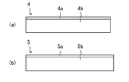
- (A) is a top view of the positive electrode plate which concerns on embodiment.
- FIG. 3B is a plan view of the negative electrode plate according to the embodiment.
- FIG. 4 is a cross-sectional view of a negative electrode current collector and a negative electrode core body laminated portion according to the embodiment, showing a state before the negative electrode current collector and the negative electrode core body laminated portion are sandwiched by a horn and an anvil.
- FIG. 4 is a cross-sectional view of a negative electrode current collector and a negative electrode core body laminated portion according to the embodiment, showing a state before the negative electrode current collector and the negative electrode core body laminated portion are sandwiched by a horn and an anvil.
- FIG. 3 is a cross-sectional view of a negative electrode current collector and a negative electrode core body laminated portion according to the embodiment, showing a state after the negative electrode current collector and the negative electrode core body laminated portion are sandwiched by a horn and an anvil.
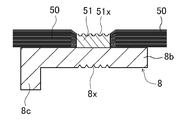
- FIG. 3 is a cross-sectional view of a negative electrode current collector and a negative electrode core body laminated portion according to the embodiment, showing a state after ultrasonic bonding of the negative electrode current collector and the negative electrode core body laminated portion.
- FIG. 5 is a plan view of a negative electrode current collector and a negative electrode core body laminated portion after ultrasonic bonding according to the embodiment.
- FIG. 1 A) And (b) is a figure which shows a mode that the unevenness
- (A) is a figure which shows before an oxidation process
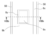
- (b) is a figure which shows after an oxidation process. It is a top view of the negative electrode electrical power collector after an oxidation process.
- FIG. 9 is a cross-sectional view of a negative electrode current collector and a negative electrode core body laminated portion according to Modification 1, showing a state before the negative electrode current collector and the negative electrode core body laminated portion are sandwiched by a horn and an anvil.
- FIG. 9 is a cross-sectional view of a negative electrode current collector and a negative electrode core body laminated portion according to Modification 1, showing a state after the negative electrode current collector and the negative electrode core body laminated portion are sandwiched by a horn and an anvil.
- FIG. 9 is a cross-sectional view of a negative electrode current collector and a negative electrode core body laminated portion according to Modification 1, showing a state after ultrasonic bonding of the negative electrode current collector and the negative electrode core body laminated portion.
- FIG. 9 is a plan view of a negative electrode current collector and a negative electrode core body laminated portion before an oxidation treatment according to Modification Example 1.
- FIG. 9 is a plan view of a negative electrode current collector and a negative electrode core body laminated portion after an oxidation treatment according to Modification Example 1.
- FIG. 16 is a sectional view taken along line XVI-XVI in FIG. 15.
- the prismatic secondary battery 100 includes a prismatic outer casing 1 having an opening at the top, and a sealing plate 2 for sealing the opening.
- the prismatic outer casing 1 and the sealing plate 2 constitute a battery case 200.
- the prismatic outer casing 1 and the sealing plate 2 are each made of metal, and are preferably made of, for example, aluminum or aluminum alloy.
- a flat wound electrode body 3 in which a strip-shaped positive electrode plate and a strip-shaped negative electrode plate are wound with a strip-shaped separator sandwiched therebetween is housed in a rectangular outer package 1 together with a non-aqueous electrolyte (not shown).
- the sealing plate 2 is provided with a gas discharge valve 15 that breaks when the pressure inside the battery case 200 exceeds a predetermined value and discharges the gas inside the battery case 200 to the outside of the battery case 200. Further, the electrolyte injection hole 16 provided in the sealing plate 2 is sealed by the sealing member 17.
- the positive electrode plate 4 has a positive electrode core body 4a made of metal and a positive electrode active material layer 4b formed on both surfaces of the positive electrode core body 4a.
- the positive electrode plate 4 has a positive electrode core exposed portion in which the positive electrode active material layer 4b is not formed on both surfaces of the positive electrode core 4a along the longitudinal direction at the end portion in the width direction.
- the positive electrode core body 4a is preferably made of aluminum or an aluminum alloy.
- the positive electrode active material layer 4b contains a positive electrode active material.
- As the positive electrode active material for example, a lithium transition metal composite oxide or the like can be used.
- the positive electrode active material layer 4b preferably contains a binder and a conductive material.
- a resin binder is preferable as the binder, and for example, polyvinylidene fluoride or the like can be used.
- a carbon material such as carbon black is preferable as the conductive member.
- the negative electrode plate 5 has a negative electrode core body 5 a made of metal and negative electrode active material layers 5 b formed on both surfaces of the negative electrode core body 5 a.
- the negative electrode plate 5 has, at the end in the width direction, a negative electrode core exposed portion in which the negative electrode active material layers 5b are not formed on both surfaces of the negative electrode core 5a along the longitudinal direction.
- the negative electrode core body 5a is preferably made of copper or a copper alloy.
- the negative electrode active material layer 5b contains a negative electrode active material.
- a carbon material such as graphite or amorphous carbon
- a silicon material such as silicon or silicon oxide, or the like can be used.
- the negative electrode active material layer 5b preferably contains a binder.
- a resin binder is preferable, and for example, styrene-butadiene rubber (SBR) and carboxymesyl cellulose (CMC) are preferably contained.
- SBR styrene-butadiene rubber
- CMC carboxymesyl cellulose
- the negative electrode active material layer 5b may include a conductive material as needed.
- the wound-type electrode body 3 has a positive electrode core exposed portion wound at one end and a negative electrode core exposed portion wound at the other end.
- the wound positive electrode core exposed portion constitutes a positive electrode core laminated portion 40 in which the positive electrode core 4a is laminated.
- the wound negative electrode core exposed portion constitutes a negative electrode core laminated portion 50 in which the negative electrode core 5a is laminated.
- the positive electrode current collector 6 is connected to the positive electrode core laminated portion 40.
- the positive electrode current collector 6 is connected to the positive electrode terminal 7 attached to the sealing plate 2.
- An inner insulating member 10 made of resin is disposed between the sealing plate 2 and the positive electrode current collector 6.
- An outer insulating member 11 made of resin is arranged between the sealing plate 2 and the positive electrode terminal 7.
- the positive electrode current collector 6 and the positive electrode terminal 7 are electrically insulated from the sealing plate 2 by the inner insulating member 10 and the outer insulating member 11.
- the positive electrode current collector 6 and the positive electrode terminal 7 are preferably made of metal, for example, aluminum or aluminum alloy.
- the negative electrode current collector 8 is connected to the negative electrode core laminated portion 50.
- the negative electrode current collector 8 is connected to the negative electrode terminal 9 attached to the sealing plate 2.
- An inner insulating member 12 made of resin is disposed between the sealing plate 2 and the negative electrode current collector 8.
- An outer insulating member 13 made of resin is arranged between the sealing plate 2 and the negative electrode terminal 9.
- the negative electrode current collector 8 and the negative electrode terminal 9 are electrically insulated from the sealing plate 2 by the inner insulating member 12 and the outer insulating member 13.
- the negative electrode current collector 8 and the negative electrode terminal 9 are preferably made of metal, for example, copper or copper alloy.
- the negative electrode terminal 9 preferably has a portion made of copper or a copper alloy and a portion made of aluminum or an aluminum alloy. Then, it is preferable that the portion made of copper or a copper alloy is connected to the negative electrode current collector 8 made of copper or a copper alloy so that the portion made of aluminum or an aluminum alloy is exposed to the outside of the sealing plate 2.
- the positive electrode terminal 7 has a flange portion 7a arranged on the outer side of the battery with respect to the sealing plate 2, and an insertion portion (not shown) formed on one surface of the flange portion 7a.
- the insertion portion penetrates a positive electrode terminal mounting hole (not shown) provided in the sealing plate 2 and is connected to the positive electrode current collector 6.
- the negative electrode terminal 9 has a collar portion 9a arranged on the outer side of the battery with respect to the sealing plate 2, and an insertion portion (not shown) formed on one surface of the collar portion 9a.
- the insertion portion penetrates a negative electrode terminal mounting hole (not shown) provided in the sealing plate 2 and is connected to the negative electrode current collector 8.
- positive electrode current collector 6 and the positive electrode terminal 7 may be electrically connected via another conductive member.
- negative electrode current collector 8 and the negative electrode terminal 9 may be electrically connected via another conductive member.
- the positive electrode current collector 6 has a base portion 6a arranged between the sealing plate 2 and the electrode body 3, and a lead portion 6b extending from the end of the base portion 6a toward the electrode body 3 side.
- the positive electrode terminal 7 is connected to the base portion 6a.
- the lead portion 6b is joined to the positive electrode core laminated portion 40.
- a rib 6c is provided at the end of the lead portion 6b in the width direction.
- the rib 6c may be omitted.
- the negative electrode current collector 8 has a base portion 8a arranged between the sealing plate 2 and the electrode body 3, and a lead portion 8b extending from the end of the base portion 8a toward the electrode body 3 side.
- the negative electrode terminal 9 is connected to the base portion 8a.
- the lead portion 8b is joined to the negative electrode core laminated portion 50.
- a rib 8c is provided at the end of the lead portion 8b in the width direction. The rib 8c can be omitted.
- a concavo-convex forming portion 6x is formed on the surface of the portion joined to the positive electrode core laminated portion 40 opposite to the surface joined to the positive electrode core laminated portion 40. ing.
- the concavo-convex forming portion 6x is formed by the anvil projection provided on the anvil of the positive electrode current collector 6 biting into the positive electrode current collector 6 when ultrasonically bonding the positive electrode current collector 6 and the positive electrode core body laminated portion 40. That is, the unevenness forming portion 6x is a pressing mark by the anvil.
- a concavo-convex forming portion 8x is formed on the surface of the portion bonded to the negative electrode core laminated portion 50 opposite to the surface bonded to the negative electrode core laminated portion 50. ing.
- the concavo-convex forming portion 8x is formed by the anvil protrusion provided on the anvil in the negative electrode current collector 8 when the negative electrode current collector 8 and the negative electrode core laminate 50 are ultrasonically bonded. That is, the unevenness forming portion 8x is a pressing mark by the anvil.
- the method of attaching the positive electrode current collector 6, the positive electrode terminal 7, the negative electrode current collector 8 and the negative electrode terminal 9 to the sealing plate 2 will be described below.
- the outer insulating member 11 is arranged on the battery outer side of the sealing plate 2
- the inner insulating member 10 is arranged on the inner surface side of the sealing plate 2.
- the base portion 6a of the positive electrode current collector 6 is arranged.
- the insertion portion of the positive electrode terminal 7 is inserted from the outside of the battery into the through hole of the outer insulating member 11, the positive electrode terminal mounting hole of the sealing plate 2, the through hole of the inner insulating member 10, and the through hole of the base portion 6a.
- the tip side of the insertion portion of the positive electrode terminal 7 is crimped onto the base portion 6a.
- the positive electrode terminal 7, the outer insulating member 11, the sealing plate 2, the inner insulating member 10 and the positive electrode current collector 6 are integrally fixed.
- the crimped portion of the tip of the insertion portion of the positive electrode terminal 7 may be welded to the base portion 6a.
- the outer side insulating member 13 is arranged on the battery outer side of the sealing plate 2, and the inner side insulation is provided on the battery inner side of the sealing plate 2.
- the member 12 and the base portion 8a of the negative electrode current collector 8 are arranged.
- the insertion portion of the negative electrode terminal 9 is inserted from the outside of the battery into the through hole of the outer insulating member 13, the negative electrode terminal mounting hole of the sealing plate 2, the through hole of the inner insulating member 12, and the through hole of the base portion 8a. Then, the tip side of the insertion portion of the negative electrode terminal 9 is crimped onto the base portion 8a.
- the negative electrode terminal 9, the outer insulating member 13, the sealing plate 2, the inner insulating member 12, and the negative electrode current collector 8 are integrally fixed.
- the crimped portion of the tip of the insertion portion of the negative electrode terminal 9 may be welded to the base portion 8a.
- the positive electrode collector 6 attached to the sealing plate 2 and the positive electrode core laminated portion 40 are joined, and the negative electrode collector 8 attached to the sealing plate 2 and the negative electrode core laminated portion 50 are joined.
- the electrode body 3 is covered with the insulating sheet 14, and the electrode body 3 covered with the insulating sheet 14 is inserted into the rectangular exterior body 1.
- the sealing plate 2 is welded to the rectangular exterior body 1 by laser welding, and the opening of the rectangular exterior body 1 is closed by the sealing plate 2.
- the nonaqueous electrolyte is injected into the battery case 200 from the electrolyte injection hole 16 of the sealing plate 2, the electrolyte injection hole 16 is sealed with the sealing member 17.
- the prismatic secondary battery 100 is obtained.
- the negative electrode core laminated portion 50 is arranged on one surface side of the lead portion 8b of the negative electrode current collector 8. Then, the negative electrode core laminated portion 50 and the lead portion 8b are sandwiched between the horn 90 and the anvil 91.
- the horn 90 has a plurality of horn protrusions 90a at its tip. Then, the horn protrusion 90a is brought into contact with the negative electrode core laminate 50.
- the anvil 91 has a plurality of anvil protrusions 91a at its tip. Then, the anvil protrusion 91a is brought into contact with the lead portion 8b.
- the horn protrusion 90a bites into the negative electrode core laminated portion 50, and the anvil protrusion 91a extends to the lead portion 8b. It will be in a state of cutting into. Then, by applying ultrasonic vibration to the horn 90, the negative electrode core bodies 5a in the negative electrode core body laminated portion 50, and the negative electrode core body laminated portion 50 and the lead portion 8b are joined together as shown in FIG. As a result, the joint portion 51 is formed in the negative electrode core laminated portion 50.
- the core-side irregularity forming portion 51x is formed on the surface of the joint portion 51.
- the lead portion 8b is formed with an unevenness forming portion 8x which is a pressing mark by the anvil 91.
- FIG. 7 is a plan view of the surface of the lead portion 8b opposite to the surface on which the negative electrode core laminated portion 50 is joined, after the negative electrode core laminated portion 50 and the lead portion 8b are ultrasonically joined.
- a concavo-convex forming portion 8x which is a pressing mark by the anvil 91 is formed.
- FIG. 8A is a sectional view taken along line VIIIa-VIIIa in FIG.
- an energy ray L such as a laser is applied to a region of the lead portion 8b of the negative electrode current collector 8 where the unevenness forming portion 8x is formed.
- the oxide film 8y is formed on the surface of the unevenness forming portion 8x of the lead portion 8b. Note that when irradiating with energy rays, the surrounding atmosphere is made to contain oxygen.
- the oxide film 8y is made of copper (II) oxide.
- FIG. 9A is an enlarged cross-sectional view of the surface of the unevenness forming portion 8x before the oxidation treatment.
- FIG. 9B is an enlarged cross-sectional view of the surface of the unevenness forming portion 8x after the oxidation treatment.
- a burr 8z made of copper or a copper alloy may be formed on the surface of the unevenness forming portion 8x pressed by the anvil 91 in the lead portion 8b during ultrasonic bonding.
- an oxide film 8y is formed on the surface of the unevenness forming portion 8x.
- the burr 8z made of copper or a copper alloy is oxidized, and the copper contained in the burr 8z becomes divalent. Therefore, even if the burr 8z is detached from the unevenness forming portion 8x, enters the electrode body 3 and moves onto the positive electrode plate 4, the divalent copper does not dissolve in the electrolytic solution during charging. Therefore, it is possible to suppress the generation of dendrites made of copper or a copper alloy on the negative electrode plate 5. Therefore, the secondary battery in which the short circuit between the positive electrode plate 4 and the negative electrode plate 5 is suppressed can be provided.
- the unevenness forming portion 8x and its periphery are oxidized in the lead portion 8b, and an oxide film 8y is formed on the surface.
- the oxide film 8y is sufficiently thicker than the oxide film formed on the surface of ordinary copper or copper alloy.
- the thickness of the oxide film 8y formed by the oxidation treatment is preferably twice or more the thickness of the natural oxide film existing on the surface of the portion not subjected to the oxidation treatment, and more preferably 5 times or more. It is more preferably 10 times or more.
- FIG. 8B is a sectional view of VIIIb-VIIIb in FIG.
- [Modification 1] 11 to 16 show a bonding mode of the negative electrode current collector and the negative electrode core body laminated portion according to the first modification.
- the shape of the lead portion of the negative electrode current collector is different from that of the above-described embodiment.
- the concave portion 108d is provided on the surface of the lead portion 108b opposite to the surface facing the negative electrode core laminated portion 50.
- the thin portion 108e is formed on the lead portion 108b.
- the negative electrode current collector 108 has a rib 108c at the widthwise end of the lead portion 108b.
- the negative electrode core laminated portion 50 is arranged on the surface of the lead portion 108b of the negative electrode current collector 108 opposite to the surface on which the recess 108d is formed. Then, the negative electrode core laminated portion 50 and the lead portion 108b are sandwiched by the horn 90 and the anvil 91.
- the anvil 91 is in contact with the bottom surface of the recess 108d formed in the lead portion 108b.
- the anvil protrusion 91a of the anvil 91 is designed to bite into the bottom surface of the recess 108d.
- the lead portion 108b and the negative electrode core laminated portion 50 are joined.
- the negative electrode core bodies 5a in the negative electrode core body stacked portion 50 are joined together, and the negative electrode core body 5a and the thin portion 108e of the lead portion 108b are joined together to form the joint portion 51.
- the concavo-convex forming portion 108x which is a pressing mark of the anvil 91 formed on the lead portion 108b, is formed on the bottom surface of the concave portion 108d.
- FIG. 14 is a plan view of the surface of the lead portion 108b opposite to the surface to which the negative electrode core laminated portion 50 is bonded, after the negative electrode core stacked portion 50 and the lead portion 108b are ultrasonically bonded.
- a concavo-convex forming portion 108x which is a pressing mark by the anvil 91 is formed.
- FIG. 13 is a sectional view taken along line XIII-XIII in FIG.
- the concavo-convex forming portion 108x is irradiated with an energy ray such as a laser, and as shown in FIGS. 15 and 16, an oxide film 108y is formed on the surface of the concavo-convex forming portion 108x of the lead portion 108b.
- the oxide film 108y is formed on the bottom surface of the recess 108d of the lead portion 108b.
- 16 is a cross-sectional view taken along line XVI-XVI in FIG.
- burrs made of copper or a copper alloy formed on the unevenness forming portion 108x and metal small pieces made of copper or a copper alloy existing on the surface of the unevenness forming portion 108x are oxidized, copper contained in the burrs and the metal small pieces is 2%. It becomes a valent oxide. Therefore, even if the oxidized burrs that have fallen off or the oxidized small metal pieces move onto the positive electrode plate 4, it is possible to prevent them from dissolving in the electrolytic solution during charging. Therefore, it is possible to suppress the generation of dendrites made of copper or a copper alloy on the negative electrode plate 5. Therefore, the secondary battery in which the short circuit between the positive electrode plate 4 and the negative electrode plate 5 is suppressed can be provided.
- the surface of the concavo-convex forming portion may be oxidized by another method.
- an oxidizing agent can be applied or sprayed on the unevenness forming portion 8x and the unevenness forming portion 108x.
- the oxidizer it is preferable to use at least one selected from the group consisting of KBr, KCl, LiBr, LiCl, CuBr, CuBr 2 , CuCl, and CuCl 2 .
- the oxidizing agent is not particularly limited as long as it can oxidize metallic copper into a copper compound in which copper is divalent.
- the surface of the concavo-convex forming portion may be oxidized by another method.
- heating the surface of the unevenness forming portion 108x at 80 to 120° C. for 5 to 200 minutes can be considered.
- the conditions for ultrasonically bonding the current collector and the core laminated portion are not particularly limited. It may be set and ultrasonic bonding may be performed. When the frequency is 20 kHz, the horn amplitude may be 50% to 90% of the maximum amplitude (for example, 50 ⁇ m).
- the oxide film on each surface of the core constituting the core laminated portion and the surface of the current collector is removed by friction, and the cores are solid-phase bonded to each other. At the same time, the core and the current collector are solid-phase bonded.
- a rectangular secondary battery having a flat spirally wound electrode body is exemplified, but a positive electrode plate and a negative electrode plate sandwiching a separator are laminated in a plurality of laminated types. It may be an electrode body. Further, the positive electrode core laminated portion and the negative electrode core laminated portion may be arranged at the end of the electrode body on the side of the sealing plate.
- the thickness of the positive electrode core is preferably 5 to 30 ⁇ m, more preferably 10 to 20 ⁇ m. Further, the number of laminated positive electrode cores in the positive electrode core laminated portion is preferably 10 to 100 layers, and more preferably 30 to 100 layers.
- the thickness of the negative electrode core is preferably 5 to 30 ⁇ m, more preferably 6 to 15 ⁇ m. Further, the number of laminated negative electrode cores in the negative electrode core laminated portion is preferably 10 to 100 layers, and more preferably 30 to 100 layers.
- Known materials can be used for the positive electrode plate, the negative electrode plate, the separator, the electrolyte, and the like.
Landscapes
- Chemical & Material Sciences (AREA)
- Chemical Kinetics & Catalysis (AREA)
- Electrochemistry (AREA)
- General Chemical & Material Sciences (AREA)
- Engineering & Computer Science (AREA)
- Materials Engineering (AREA)
- Manufacturing & Machinery (AREA)
- Connection Of Batteries Or Terminals (AREA)
- Cell Electrode Carriers And Collectors (AREA)
- Secondary Cells (AREA)
Abstract
正極板と負極板の短絡が抑制された信頼性の高い二次電池を提供する。負極板と正極板を有する電極体と、負極板に電気的に接続された銅又は銅合金製の負極集電体と、を備え、負極板は、銅又は銅合金製の負極芯体と、負極芯体上に形成された負極活物質層を有し、電極体は、負極芯体が積層された負極芯体積層部(50)を有し、負極芯体積層部(50)が負極集電体(8)に接合された二次電池の製造方法であって、負極芯体積層部(50)と負極集電体(8)をホーンとアンビルで挟み込み、アンビルが負極集電体(8)と接する状態で、負極芯体積層部(50)と負極集電体を超音波接合して接合部を形成する接合工程と、接合工程において負極集電体(8)においてアンビルと接していた部分を酸化させる酸化処理工程と、を有する。
Description
本開示は、二次電池及びその製造方法に関する。
リチウムイオン二次電池等の二次電池は、正極板及び負極板を含む電極体を電解質とともに電池ケース内に収容した構造を有している。電極体を構成する正極板及び負極板は、それぞれ金属製の芯体の表面に活物質層が形成されている。そして、正極板及び負極板のそれぞれに設けられた芯体露出部は、集電体を介して、電池ケースに取り付けられた端子と電気的に接続されている。
芯体と集電体とを接合する方法として、超音波接合により接合する方法が知られている。超音波接合は、積層された芯体と集電体とをホーンとアンビルとで挟み込みながら、超音波による振動エネルギーを接合面に加えることによって行われる。なお、積層された芯体と集電体とを確実に挟み込むために、ホーン及びアンビルの表面には、それぞれ複数の突起部が設けられている。
例えば、特許文献1には、ホーンの表面に設けられた突起部の形状を円弧状にしたり、ホーンの周辺に、突起部が形成されていないマージン領域を設ける方法が開示されている。
本開示の一つの目的は、正極板と負極板の短絡が抑制された二次電池を提供することである。
本開示の一形態の二次電池の製造方法は、
第1電極板と、
前記第1電極板と極性の異なる第2電極板と、
前記第1電極板と前記第2電極板を含む電極体と、
前記第1電極板に電気的に接続された銅又は銅合金製の第1電極集電体と、を備え、
前記第1電極板は、銅又は銅合金製の第1電極芯体と、前記第1電極芯体上に形成された第1電極活物質層を有し、
前記電極体は、前記第1電極芯体が積層された前記第1電極芯体積層部を有し、
前記第1電極芯体積層部が前記第1電極集電体に接合された二次電池の製造方法であって、
前記第1電極芯体積層部と前記第1電極集電体をホーンとアンビルで挟み込み、前記アンビルが前記第1電極集電体と接する状態で、前記第1電極芯体積層部と前記第1電極集電体を超音波接合して接合部を形成する接合工程と、
前記接合工程において前記第1電極集電体において前記アンビルと接していた部分を酸化させる酸化処理工程と、
を有する。
第1電極板と、
前記第1電極板と極性の異なる第2電極板と、
前記第1電極板と前記第2電極板を含む電極体と、
前記第1電極板に電気的に接続された銅又は銅合金製の第1電極集電体と、を備え、
前記第1電極板は、銅又は銅合金製の第1電極芯体と、前記第1電極芯体上に形成された第1電極活物質層を有し、
前記電極体は、前記第1電極芯体が積層された前記第1電極芯体積層部を有し、
前記第1電極芯体積層部が前記第1電極集電体に接合された二次電池の製造方法であって、
前記第1電極芯体積層部と前記第1電極集電体をホーンとアンビルで挟み込み、前記アンビルが前記第1電極集電体と接する状態で、前記第1電極芯体積層部と前記第1電極集電体を超音波接合して接合部を形成する接合工程と、
前記接合工程において前記第1電極集電体において前記アンビルと接していた部分を酸化させる酸化処理工程と、
を有する。
本願発明者等は、積層された複数の芯体と集電体とを超音波接合により接合した後に、接合部で発生した金属小片(発塵)を調べていたところ、芯体の膜みよりも大きい金属小片が含まれていることに気がついた。その後の詳細な分析から、このような大きさの金属小片は、芯体から剥がれてできたものではなく、集電体から削り取られてできたものであることが分かった。
集電体が銅又は銅合金製である場合、超音波接合の際に集電体から削り取られた金属小片は銅又は銅合金からなる金属小片(銅片、銅合金片)となる。そして、例えば電解液を電池ケース内に注入する際などに、この銅又は銅合金からなる金属小片が正極板上に移動することがある。正極板上に銅又は銅合金からなる金属小片が存在すると、二次電池の充放電により正極板上の銅又は銅合金からなる金属小片が電解液に溶解するとともに、負極板上でデンドライトに成長する虞がある。その結果、デンドライトがセパレータを突き破り、正極板と負極板との間で内部短絡が発生する虞がある。
本開示の一形態の二次電池の製造方法によると、集電体において超音波接合の際にアンビルが接した部分を酸化処理することにより、銅又は銅合金からなる金属小片ないし銅又は銅合金からなる金属小片となりうるバリを酸化させることができる。酸化された銅又は銅合金からなる金属小片が正極板上に存在しても、二次電池の充電によっては電解液に溶解しない。したがって、負極板上に銅又は銅合金からなるデンドライトが生じることを抑制できる。よって、正極板と負極板の短絡が抑制された二次電池を提供することができる。なお、第1電極板は正極板であってもよいし、負極板であってもよい。
本開示の一形態の二次電池は、
第1電極板と、
前記第1電極板と極性の異なる第2電極板と、
前記第1電極板と前記第2電極板を含む電極体と、
前記第1電極板に電気的に接続された銅又は銅合金製の第1電極集電体と、を備え、
前記第1電極板は、銅又は銅合金製の第1電極芯体と、前記第1電極芯体上に形成された第1電極活物質層を有し、
前記電極体は、前記第1電極芯体が積層された前記第1電極芯体積層部を有し、
前記第1電極芯体積層部が前記第1電極集電体に接合された二次電池であって、
前記第1電極集電体において、前記第1電極芯体積層部が接合された面と反対側の面には凹凸形成部が形成され、
前記凹凸形成部の表面には、2価の銅を含む銅化合物からなる層が形成され、
前記2価の銅を含む銅化合物からなる層の厚みは、前記第1電極集電体において前記凹凸形成部から離れた位置にある部分の表面に形成された酸化膜よりも厚みの大きい二次電池。
第1電極板と、
前記第1電極板と極性の異なる第2電極板と、
前記第1電極板と前記第2電極板を含む電極体と、
前記第1電極板に電気的に接続された銅又は銅合金製の第1電極集電体と、を備え、
前記第1電極板は、銅又は銅合金製の第1電極芯体と、前記第1電極芯体上に形成された第1電極活物質層を有し、
前記電極体は、前記第1電極芯体が積層された前記第1電極芯体積層部を有し、
前記第1電極芯体積層部が前記第1電極集電体に接合された二次電池であって、
前記第1電極集電体において、前記第1電極芯体積層部が接合された面と反対側の面には凹凸形成部が形成され、
前記凹凸形成部の表面には、2価の銅を含む銅化合物からなる層が形成され、
前記2価の銅を含む銅化合物からなる層の厚みは、前記第1電極集電体において前記凹凸形成部から離れた位置にある部分の表面に形成された酸化膜よりも厚みの大きい二次電池。
本開示の一形態の二次電池の構成であると、正極板と負極板の短絡が抑制された二次電池を提供することができる。
本開示によれば、正極板と負極板の短絡が抑制された二次電池を提供することができる。
以下、本開示の実施形態に係る二次電池としての角形二次電池100について、図面を参照しながら説明する。なお、本開示の範囲は、以下の実施の形態に限定されず、本開示の技術的思想の範囲内で任意に変更可能である。
まず、一実施形態に係る角形二次電池100の構成を説明する。図1及び図2に示すように、角形二次電池100は、上方に開口を有する角形外装体1と、当該開口を封口する封口板2を備える。角形外装体1及び封口板2により電池ケース200が構成される。角形外装体1及び封口板2はそれぞれ金属製であり、例えば、アルミニウム又はアルミニウム合金製であることが好ましい。角形外装体1内には、帯状の正極板と帯状の負極板とが帯状のセパレータを挟んで巻回された偏平状の巻回型の電極体3が非水電解質(図示省略)と共に収容される。角形外装体1と電極体3の間には樹脂製の絶縁シート14が配置されている。封口板2には電池ケース200内の圧力が所定値以上となると破断し、電池ケース200内のガスを電池ケース200外に排出するガス排出弁15が設けられている。また、封口板2に設けられた電解質注液孔16が、封止部材17により封止されている。
図3(a)に示すように、正極板4は、金属製の正極芯体4aと、正極芯体4aの両面に形成された正極活物質層4bを有する。正極板4は、幅方向の端部に、長手方向に沿って、正極芯体4aの両面に正極活物質層4bが形成されていない正極芯体露出部を有する。正極芯体4aは、アルミニウム又はアルミニウム合金製であることが好ましい。正極活物質層4bは、正極活物質を含む。正極活物質としては、例えば、リチウム遷移金属複合酸化物等を用いることができる。また、正極活物質層4bは、バインダー及び導電材を含むことが好ましい。バインダーとしては樹脂製のバインダーが好ましく、例えばポリフッ化ビニリデン等を用いることができる。導電部材としてはカーボンブラック等の炭素材料が好ましい。
図3(b)に示すように、負極板5は、金属製の負極芯体5aと、負極芯体5aの両面に形成された負極活物質層5bを有する。負極板5は、幅方向の端部に、長手方向に沿って、負極芯体5aの両面に負極活物質層5bが形成されていない負極芯体露出部が形成されている。負極芯体5aは、銅又は銅合金製であることが好ましい。負極活物質層5bは、負極活物質を含む。負極活物質としては、例えば、黒鉛や非晶質炭素等の炭素材料、シリコンや酸化シリコン等のシリコン材料等を用いることができる。負極活物質層5bは、バインダーを含むことが好ましい。バインダーとしては樹脂製のバインダーが好ましく、例えばスチレンブタジエンゴム(SBR)及びカルボキシメシルセルロース(CMC)を含むことが好ましい。負極活物質層5bは必要に応じて導電材を含んでもよい。
巻回型の電極体3は、一方の端部に巻回された正極芯体露出部を有し、他方の端部に巻回された負極芯体露出部を有する。巻回された正極芯体露出部は、正極芯体4aが積層された正極芯体積層部40を構成する。巻回された負極芯体露出部は、負極芯体5aが積層された負極芯体積層部50を構成する。
正極芯体積層部40には正極集電体6が接続されている。正極集電体6は封口板2に取り付けられた正極端子7と接続されている。封口板2と正極集電体6の間には樹脂製の内部側絶縁部材10が配置されている。封口板2と正極端子7の間には樹脂製の外部側絶縁部材11が配置されている。内部側絶縁部材10及び外部側絶縁部材11により、正極集電体6及び正極端子7は封口板2と電気的に絶縁されている。正極集電体6及び正極端子7は、金属製であり、例えば、アルミニウム又はアルミニウム合金製であることが好ましい。
負極芯体積層部50には負極集電体8が接続されている。負極集電体8は封口板2に取り付けられた負極端子9と接続されている。封口板2と負極集電体8の間には樹脂製の内部側絶縁部材12が配置されている。封口板2と負極端子9の間には樹脂製の外部側絶縁部材13が配置されている。内部側絶縁部材12及び外部側絶縁部材13により、負極集電体8及び負極端子9は封口板2と電気的に絶縁されている。負極集電体8及び負極端子9は、金属製であり、例えば、銅又は銅合金製であることが好ましい。また、負極端子9は、銅又は銅合金からなる部分と、アルミニウム又はアルミニウム合金からなる部分を有することが好ましい。そして、銅又は銅合金からなる部分を銅又は銅合金からなる負極集電体8と接続し、アルミニウム又はアルミニウム合金からなる部分が封口板2よりも外部側に露出するようにすることが好ましい。
正極端子7は、封口板2よりも電池外部側に配置される鍔部7aと、鍔部7aの一方の面に形成された挿入部(図示省略)を有する。挿入部が封口板2に設けられた正極端子取り付け孔(図示省略)を貫通し、正極集電体6に接続される。
負極端子9は、封口板2よりも電池外部側に配置される鍔部9aと、鍔部9aの一方の面に形成された挿入部(図示省略)を有する。挿入部が封口板2に設けられた負極端子取り付け孔(図示省略)を貫通し、負極集電体8に接続される。
負極端子9は、封口板2よりも電池外部側に配置される鍔部9aと、鍔部9aの一方の面に形成された挿入部(図示省略)を有する。挿入部が封口板2に設けられた負極端子取り付け孔(図示省略)を貫通し、負極集電体8に接続される。
なお、正極集電体6と正極端子7を、他の導電部材を介して電気的に接続してもよい。また、負極集電体8と負極端子9を、他の導電部材を介して電気的に接続してもよい。
正極集電体6は、封口板2と電極体3の間に配置されるベース部6aと、ベース部6aの端部から電極体3側に延びるリード部6bを有する。ベース部6aに正極端子7が接続されている。リード部6bが正極芯体積層部40に接合されている。リード部6bの幅方向の端部にはリブ6cが設けられる。なお、リブ6cを省略することもできる。
負極集電体8は、封口板2と電極体3の間に配置されるベース部8aと、ベース部8aの端部から電極体3側に延びるリード部8bを有する。ベース部8aに負極端子9が接続されている。リード部8bが負極芯体積層部50に接合されている。リード部8bの幅方向の端部にはリブ8cが設けられている。なお、リブ8cを省略することもできる。
負極集電体8は、封口板2と電極体3の間に配置されるベース部8aと、ベース部8aの端部から電極体3側に延びるリード部8bを有する。ベース部8aに負極端子9が接続されている。リード部8bが負極芯体積層部50に接合されている。リード部8bの幅方向の端部にはリブ8cが設けられている。なお、リブ8cを省略することもできる。
正極集電体6のリード部6bにおいて、正極芯体積層部40と接合された部分の正極芯体積層部40と接合された面とは反対側の面には、凹凸形成部6xが形成されている。この凹凸形成部6xは、正極集電体6と正極芯体積層部40を超音波接合する際に、正極集電体6にアンビルに設けられたアンビル突起が食い込むことにより形成される。即ち、凹凸形成部6xは、アンビルによる押圧痕である。
負極集電体8のリード部8bにおいて、負極芯体積層部50と接合された部分の負極芯体積層部50と接合された面とは反対側の面には、凹凸形成部8xが形成されている。この凹凸形成部8xは、負極集電体8と負極芯体積層部50を超音波接合する際に、負極集電体8にアンビルに設けられたアンビル突起が食い込むことにより形成される。即ち、凹凸形成部8xは、アンビルによる押圧痕である。
[封口板への各部品取り付け]
以下に、正極集電体6、正極端子7、負極集電体8及び負極端子9の封口板2への取り付け方法を説明する。
まず、封口板2に設けられた正極端子取り付け孔(図示省略)の周囲において、封口板2の電池外部側に外部側絶縁部材11を配置し、封口板2の内面側に内部側絶縁部材10及び正極集電体6のベース部6aを配置する。次に、正極端子7の挿入部を電池外部側から、外部側絶縁部材11の貫通孔、封口板2の正極端子取り付け孔、内部側絶縁部材10の貫通孔及びベース部6aの貫通孔に挿入し、正極端子7の挿入部の先端側をベース部6a上にカシメる。これにより、正極端子7、外部側絶縁部材11、封口板2、内部側絶縁部材10及び正極集電体6が一体的に固定される。なお、正極端子7の挿入部の先端のカシメられた部分をベース部6aに溶接してもよい。
以下に、正極集電体6、正極端子7、負極集電体8及び負極端子9の封口板2への取り付け方法を説明する。
まず、封口板2に設けられた正極端子取り付け孔(図示省略)の周囲において、封口板2の電池外部側に外部側絶縁部材11を配置し、封口板2の内面側に内部側絶縁部材10及び正極集電体6のベース部6aを配置する。次に、正極端子7の挿入部を電池外部側から、外部側絶縁部材11の貫通孔、封口板2の正極端子取り付け孔、内部側絶縁部材10の貫通孔及びベース部6aの貫通孔に挿入し、正極端子7の挿入部の先端側をベース部6a上にカシメる。これにより、正極端子7、外部側絶縁部材11、封口板2、内部側絶縁部材10及び正極集電体6が一体的に固定される。なお、正極端子7の挿入部の先端のカシメられた部分をベース部6aに溶接してもよい。
同様に、封口板2に設けられた負極端子取り付け孔(図示省略)の周囲において、封口板2の電池外部側に外部側絶縁部材13を配置し、封口板2の電池内部側に内部側絶縁部材12及び負極集電体8のベース部8aを配置する。次に、負極端子9の挿入部を電池外部側から、外部側絶縁部材13の貫通孔、封口板2の負極端子取り付け孔、内部側絶縁部材12の貫通孔及びベース部8aの貫通孔に挿入し、負極端子9の挿入部の先端側をベース部8a上にカシメる。これにより、負極端子9、外部側絶縁部材13、封口板2、内部側絶縁部材12及び負極集電体8が一体的に固定される。なお、負極端子9の挿入部の先端のカシメられた部分をベース部8aに溶接してもよい。
[角形二次電池100の組立て]
封口板2に取り付けられた正極集電体6と正極芯体積層部40を接合し、封口板2に取り付けられた負極集電体8と負極芯体積層部50を接合する。そして、電極体3を絶縁シート14で覆い、絶縁シート14で覆われた電極体3を角形外装体1に挿入する。そして、封口板2を角形外装体1にレーザー溶接により溶接し、角形外装体1の開口を封口板2で封口する。封口板2の電解質注液孔16から非水電解質を電池ケース200内に注入した後、電解質注液孔16を封止部材17で封止する。これにより角形二次電池100となる。
封口板2に取り付けられた正極集電体6と正極芯体積層部40を接合し、封口板2に取り付けられた負極集電体8と負極芯体積層部50を接合する。そして、電極体3を絶縁シート14で覆い、絶縁シート14で覆われた電極体3を角形外装体1に挿入する。そして、封口板2を角形外装体1にレーザー溶接により溶接し、角形外装体1の開口を封口板2で封口する。封口板2の電解質注液孔16から非水電解質を電池ケース200内に注入した後、電解質注液孔16を封止部材17で封止する。これにより角形二次電池100となる。
以下、負極集電体8と負極芯体積層部50の接合方法を例に、集電体と芯体積層部の接合方法を説明する。なお、正極集電体6と正極芯体積層部40の接合も同様の方法で行うことができる。
[集電体と芯体積層部の接合]
図4に示すように、負極集電体8のリード部8bの一方の面側に負極芯体積層部50を配置する。そして、ホーン90とアンビル91で、負極芯体積層部50とリード部8bを挟み込む。ホーン90は先端に複数のホーン突起90aを有する。そして、ホーン突起90aが負極芯体積層部50と接するようにする。アンビル91は先端に複数のアンビル突起91aを有する。そして、アンビル突起91aがリード部8bと接するようにする。
図4に示すように、負極集電体8のリード部8bの一方の面側に負極芯体積層部50を配置する。そして、ホーン90とアンビル91で、負極芯体積層部50とリード部8bを挟み込む。ホーン90は先端に複数のホーン突起90aを有する。そして、ホーン突起90aが負極芯体積層部50と接するようにする。アンビル91は先端に複数のアンビル突起91aを有する。そして、アンビル突起91aがリード部8bと接するようにする。
図5に示すように、ホーン90とアンビル91で、負極芯体積層部50とリード部8bを挟み込むことにより、ホーン突起90aが負極芯体積層部50に食い込み、アンビル突起91aがリード部8bに食い込んだ状態とする。そして、ホーン90に超音波振動を与えることにより、図6に示すように負極芯体積層部50における負極芯体5a同士、及び負極芯体積層部50とリード部8bが接合される。これにより、負極芯体積層部50に接合部51が形成される。
接合部51の表面には、芯体側凹凸形成部51xが形成される。また、リード部8bには、アンビル91による押圧痕である凹凸形成部8xが形成される。
図7は、負極芯体積層部50とリード部8bが超音波接合された後の、リード部8bにおいて負極芯体積層部50が接合される面とは反対側の面の平面図である。リード部8bにおいて接合部51が形成された部分の反対側にはアンビル91による押圧痕である凹凸形成部8xが形成される。
図8(a)は、図7におけるVIIIa-VIIIaの断面図である。図8(a)に示すように、負極集電体8のリード部8bにおいて凹凸形成部8xが形成された領域にレーザー等のエネルギー線Lを照射する。これにより、図8(b)に示すように、リード部8bの凹凸形成部8xの表面に酸化膜8yが形成される。なお、エネルギー線を照射する際、周囲の雰囲気は酸素を含むようにする。ここで、酸化膜8yは酸化銅(II)からなる。
図9(a)は酸化処理前の凹凸形成部8xの表面の拡大断面図である。図9(b)は酸化処理後の凹凸形成部8xの表面の拡大断面図である。図9(a)に示すように、超音波接合の際にリード部8bにおいてアンビル91に押圧された凹凸形成部8xの表面には銅又は銅合金からなるバリ8zが生じるおそれがある。図9(b)に示すように凹凸形成部8xの表面を酸化処理することにより、凹凸形成部8xの表面には酸化膜8yが形成される。そして、銅又は銅合金からなるバリ8zが酸化され、バリ8zに含まれる銅は二価となる。このため、バリ8zが凹凸形成部8xから脱離し、電極体3内に侵入し正極板4上に移動しても、充電の際に二価の銅は電解液に溶解しない。したがって、負極板5上に銅又は銅合金からなるデンドライトが生じることを抑制できる。よって、正極板4と負極板5の短絡が抑制された二次電池を提供することができる。
なお、図10に示すように、リード部8bにおいて凹凸形成部8x及びその周辺が酸化処理され、表面に酸化膜8yが形成されることが好ましい。なお、この酸化膜8yは、通常の銅又は銅合金の表面に形成される酸化膜よりも十分に厚みが大きい。例えば、
酸化処理により形成された酸化膜8yの厚みは、酸化処理が行われていない部分の表面に存在する自然酸化膜の厚みの2倍以上であることが好ましく、5倍以上であることがより好ましく、10倍以上であることが更に好ましい。図8(b)は、図10におけるVIIIb-VIIIbの断面図である。
酸化処理により形成された酸化膜8yの厚みは、酸化処理が行われていない部分の表面に存在する自然酸化膜の厚みの2倍以上であることが好ましく、5倍以上であることがより好ましく、10倍以上であることが更に好ましい。図8(b)は、図10におけるVIIIb-VIIIbの断面図である。
[変形例1]
図11~16に、変形例1に係る負極集電体と負極芯体積層部の接合形態を示す。変形例1では、上述の実施形態とは負極集電体のリード部の形状が異なる。変形例1に係る負極集電体108では、リード部108bにおいて負極芯体積層部50と対向する面とは反対側の面に凹部108dが設けられている。これにより、リード部108bに薄肉部108eが形成されている。負極集電体108は、リード部108bの幅方向の端部にリブ108cを有する。
図11~16に、変形例1に係る負極集電体と負極芯体積層部の接合形態を示す。変形例1では、上述の実施形態とは負極集電体のリード部の形状が異なる。変形例1に係る負極集電体108では、リード部108bにおいて負極芯体積層部50と対向する面とは反対側の面に凹部108dが設けられている。これにより、リード部108bに薄肉部108eが形成されている。負極集電体108は、リード部108bの幅方向の端部にリブ108cを有する。
図11に示すように、負極集電体108のリード部108bにおいて凹部108dが形成された面とは反対側の面に負極芯体積層部50を配置する。そして、ホーン90及びアンビル91で、負極芯体積層部50とリード部108bを挟み込む。
図12に示すように、アンビル91がリード部108bに形成された凹部108dの底面に接するようにする。なお、アンビル91のアンビル突起91aが凹部108dの底面に食い込むようにする。
図13に示すように、リード部108bの薄肉部108eにおいて、リード部108bと負極芯体積層部50が接合される。負極芯体積層部50における負極芯体5a同士、及び負極芯体5aとリード部108bの薄肉部108eが接合されて、接合部51が形成される。リード部108bに形成されるアンビル91の押圧痕である凹凸形成部108xは、凹部108dの底面に形成される。
図14は、負極芯体積層部50とリード部108bが超音波接合された後の、リード部108bにおいて負極芯体積層部50が接合される面とは反対側の面の平面図である。リード部108bにおいて接合部51が形成された部分の反対側にはアンビル91による押圧痕である凹凸形成部108xが形成される。なお、図13は、図14におけるXIII-XIIIの断面図である。
次に、凹凸形成部108xにレーザー等のエネルギー線を照射し、図15及び図16に示すように、リード部108bの凹凸形成部108xの表面に酸化膜108yが形成される。酸化膜108yは、リード部108bの凹部108dの底面に形成される。なお、図16は図15におけるXVI-XVIの断面図である。
凹凸形成部108xに形成された銅又は銅合金からなるバリや、凹凸形成部108xの表面に存在した銅又は銅合金からなる金属小片が酸化されるため、バリや金属小片に含まれる銅が2価の酸化物となる。よって、脱落した酸化されたバリや、酸化された金属小片が正極板4上に移動することがあっても、充電時にそれらが電解液に溶解することを抑制できる。したがって、負極板5上に銅又は銅合金からなるデンドライトが生じることを抑制できる。よって、正極板4と負極板5の短絡が抑制された二次電池を提供することができる。
なお、凹凸形成部108xがリード部108bの凹部108dの底面に形成されていると、酸化処理を行う領域を特定し易く、安定的に酸化処理を行うことができる。
[変形例2]
上述の実施形態及び変形例1では凹凸形成部にエネルギー線を照射する例を示したが、他の方法で凹凸形成部の表面を酸化処理してもよい。例えば、実施形態における凹凸形成部8x、変形例1における凹凸形成部108xの表面に酸化剤を接触させることにより凹凸形成部8x、凹凸形成部108xの表面を酸化することも考えられる。例えば、凹凸形成部8xや凹凸形成部108xに酸化剤を塗布又は吹き付けることができる。
上述の実施形態及び変形例1では凹凸形成部にエネルギー線を照射する例を示したが、他の方法で凹凸形成部の表面を酸化処理してもよい。例えば、実施形態における凹凸形成部8x、変形例1における凹凸形成部108xの表面に酸化剤を接触させることにより凹凸形成部8x、凹凸形成部108xの表面を酸化することも考えられる。例えば、凹凸形成部8xや凹凸形成部108xに酸化剤を塗布又は吹き付けることができる。
酸化剤としては、KBr、KCl、LiBr、LiCl、CuBr、CuBr2、CuCl及びCuCl2からなる群から選択される少なくとも一つを用いることが好ましい。なお、酸化剤は、金属銅を、銅が2価である銅化合物に酸化できるものであれば特に限定されない。
[変形例3]
上述の実施形態及び変形例1では凹凸形成部にエネルギー線を照射する例を示したが、他の方法で凹凸形成部の表面を酸化処理してもよい。例えば、実施形態における凹凸形成部8x、変形例1における凹凸形成部108xの表面を、酸素を含有する雰囲気下で所定時間加熱することが考えられる。例えば、80~120℃で5~200分間、凹凸形成部108xの表面を加熱することが考えられる。なお、この際、電極体3を構成するセパレータ等に悪影響を及ぼさないように、凹凸形成部108xの表面近傍を局所的に加熱することが好ましい。
上述の実施形態及び変形例1では凹凸形成部にエネルギー線を照射する例を示したが、他の方法で凹凸形成部の表面を酸化処理してもよい。例えば、実施形態における凹凸形成部8x、変形例1における凹凸形成部108xの表面を、酸素を含有する雰囲気下で所定時間加熱することが考えられる。例えば、80~120℃で5~200分間、凹凸形成部108xの表面を加熱することが考えられる。なお、この際、電極体3を構成するセパレータ等に悪影響を及ぼさないように、凹凸形成部108xの表面近傍を局所的に加熱することが好ましい。
[超音波接合]
集電体と芯体積層部を超音波接合する際の条件は、特に限定されないが、例えば、ホーン荷重を1000N~2500N(100kgf~250kgf)、周波数を19kHz~30kHz、接合時間を200ms~500msに設定して超音波接合を行ってもよい。また、周波数が20kHzの場合、ホーン振幅を最大振幅(例えば50μm)の50%~90%としてもよい。芯体積層部に超音波振動が加えられることにより、芯体積層部を構成する芯体の各表面、集電体の表面の酸化膜が摩擦によって取り除かれ、芯体同士が固相接合されると共に、芯体と集電体が固相接合される。
集電体と芯体積層部を超音波接合する際の条件は、特に限定されないが、例えば、ホーン荷重を1000N~2500N(100kgf~250kgf)、周波数を19kHz~30kHz、接合時間を200ms~500msに設定して超音波接合を行ってもよい。また、周波数が20kHzの場合、ホーン振幅を最大振幅(例えば50μm)の50%~90%としてもよい。芯体積層部に超音波振動が加えられることにより、芯体積層部を構成する芯体の各表面、集電体の表面の酸化膜が摩擦によって取り除かれ、芯体同士が固相接合されると共に、芯体と集電体が固相接合される。
[ブローないし吸引]
芯体積層部と集電体を超音波接合した後、酸化処理を行う前に、凹凸形成部をブローないし吸引することにより、凹凸形成部に付着した金属小片を可能な限り除去することが好ましい。
芯体積層部と集電体を超音波接合した後、酸化処理を行う前に、凹凸形成部をブローないし吸引することにより、凹凸形成部に付着した金属小片を可能な限り除去することが好ましい。
<その他>
上述の実施形態では、二次電池として、偏平状の巻回電極体を有する角形二次電池を例示したが、セパレータを挟んで正極板と負極板とが交互に複数枚積層された積層型の電極体であってもよい。また、電極体における封口板側の端部に正極芯体積層部と負極芯体積層部が配置される構成であってもよい。
上述の実施形態では、二次電池として、偏平状の巻回電極体を有する角形二次電池を例示したが、セパレータを挟んで正極板と負極板とが交互に複数枚積層された積層型の電極体であってもよい。また、電極体における封口板側の端部に正極芯体積層部と負極芯体積層部が配置される構成であってもよい。
正極芯体がアルミニウム又はアルミニウム合金製である場合、正極芯体の厚みは5~30μmであることが好ましく、10~20μmであることがより好ましい。また、正極芯体積層部における正極芯体の積層数は10~100層であることが好ましく、30~100層がより好ましい。
負極芯体が銅又は銅合金製である場合、負極芯体の厚みは5~30μmであることが好ましく、6~15μmであることがより好ましい。また、負極芯体積層部における負極芯体の積層数は10~100層であることが好ましく、30~100層がより好ましい。
正極板、負極板、セパレータ、電解質等に関しては、公知の材料を用いることができる。
100・・・角形二次電池
200・・・電池ケース
1・・・角形外装体 2・・・封口板
3・・・電極体
4・・・正極板
4a・・・正極芯体
4b・・・正極活物質層
5・・・負極板
5a・・・負極芯体
5b・・・負極活物質層
6・・・正極集電体
6a・・・ベース部
6b・・・リード部
6c・・・リブ
6x・・・凹凸形成部
7・・・正極端子
7a・・・鍔部
8・・・負極集電体
8a・・・ベース部
8b・・・リード部
8c・・・リブ
8x・・・凹凸形成部
8y・・・酸化膜
9・・・負極端子
9a・・・鍔部
10・・・内部側絶縁部材
11・・・外部側絶縁部材
12・・・内部側絶縁部材
13・・・外部側絶縁部材
14・・・絶縁シート
15・・・ガス排出弁
16・・・電解質注液孔
17・・・封止部材
50・・・負極芯体積層部
51・・・接合部
51x・・・芯体側凹凸形成部
90・・・ホーン
90a・・・ホーン突起
91・・・アンビル
91a・・・アンビル突起
108・・・負極集電体
108b・・・リード部
108c・・・リブ
108d・・・凹部
108e・・・薄肉部
108x・・・凹凸形成部
108y・・・酸化膜
200・・・電池ケース
1・・・角形外装体 2・・・封口板
3・・・電極体
4・・・正極板
4a・・・正極芯体
4b・・・正極活物質層
5・・・負極板
5a・・・負極芯体
5b・・・負極活物質層
6・・・正極集電体
6a・・・ベース部
6b・・・リード部
6c・・・リブ
6x・・・凹凸形成部
7・・・正極端子
7a・・・鍔部
8・・・負極集電体
8a・・・ベース部
8b・・・リード部
8c・・・リブ
8x・・・凹凸形成部
8y・・・酸化膜
9・・・負極端子
9a・・・鍔部
10・・・内部側絶縁部材
11・・・外部側絶縁部材
12・・・内部側絶縁部材
13・・・外部側絶縁部材
14・・・絶縁シート
15・・・ガス排出弁
16・・・電解質注液孔
17・・・封止部材
50・・・負極芯体積層部
51・・・接合部
51x・・・芯体側凹凸形成部
90・・・ホーン
90a・・・ホーン突起
91・・・アンビル
91a・・・アンビル突起
108・・・負極集電体
108b・・・リード部
108c・・・リブ
108d・・・凹部
108e・・・薄肉部
108x・・・凹凸形成部
108y・・・酸化膜
Claims (8)
- 第1電極板と、
前記第1電極板と極性の異なる第2電極板と、
前記第1電極板と前記第2電極板を含む電極体と、
前記第1電極板に電気的に接続された銅又は銅合金製の第1電極集電体と、を備え、
前記第1電極板は、銅又は銅合金製の第1電極芯体と、前記第1電極芯体上に形成された第1電極活物質層を有し、
前記電極体は、前記第1電極芯体が積層された前記第1電極芯体積層部を有し、
前記第1電極芯体積層部が前記第1電極集電体に接合された二次電池の製造方法であって、
前記第1電極芯体積層部と前記第1電極集電体をホーンとアンビルで挟み込み、前記アンビルが前記第1電極集電体と接する状態で、前記第1電極芯体積層部と前記第1電極集電体を超音波接合して接合部を形成する接合工程と、
前記接合工程において前記第1電極集電体において前記アンビルと接していた部分を酸化させる酸化処理工程と、
を有する二次電池の製造方法。 - 前記酸化処理工程において、前記第1電極集電体において前記アンビルと接していた部分にエネルギー線を照射する請求項1に記載の二次電池の製造方法。
- 前記酸化処理工程において、前記第1電極集電体において前記アンビルと接していた部分に酸化剤を接触させる請求項1に記載の二次電池の製造方法。
- 前記酸化剤は、KBr、KCl、LiBr、LiCl、CuBr、CuBr2、CuCl及びCuCl2からなる群から選択される少なくとも一つである請求項3に記載の二次電池の製造方法。
- 前記酸化処理工程において、前記第1電極集電体において前記アンビルと接していた部分を、酸素を含有する雰囲気下で加熱する請求項1に記載の二次電池の製造方法。
- 前記接合工程と前記酸化処理工程の間に、前記第1電極集電体において前記アンビルと接していた部分をブローないし吸引する工程を有する請求項1~5のいずれかに記載の二次電池の製造方法。
- 第1電極板と、
前記第1電極板と極性の異なる第2電極板と、
前記第1電極板と前記第2電極板を含む電極体と、
前記第1電極板に電気的に接続された銅又は銅合金製の第1電極集電体と、を備え、
前記第1電極板は、銅又は銅合金製の第1電極芯体と、前記第1電極芯体上に形成された第1電極活物質層を有し、
前記電極体は、前記第1電極芯体が積層された前記第1電極芯体積層部を有し、
前記第1電極芯体積層部が前記第1電極集電体に接合された二次電池であって、
前記第1電極集電体において、前記第1電極芯体積層部が接合された面と反対側の面には凹凸形成部が形成され、
前記凹凸形成部の表面には、2価の銅を含む銅化合物からなる層が形成され、
前記2価の銅を含む銅化合物からなる層の厚みは、前記第1電極集電体において前記凹凸形成部から離れた位置にある部分の表面に形成された酸化膜よりも厚みの大きい二次電池。 - 前記2価の銅を含む銅化合物からなる層の厚みは、前記第1電極集電体において前記凹凸形成部から離れた位置にある部分の表面に形成された酸化膜の厚みの2倍以上である請求項7に記載の二次電池。
Priority Applications (3)
| Application Number | Priority Date | Filing Date | Title |
|---|---|---|---|
| JP2020569447A JP7361054B2 (ja) | 2019-01-29 | 2019-12-24 | 二次電池及びその製造方法 |
| CN201980090266.0A CN113348573A (zh) | 2019-01-29 | 2019-12-24 | 二次电池及其制造方法 |
| US17/424,268 US11769936B2 (en) | 2019-01-29 | 2019-12-24 | Secondary battery and method for manufacturing same |
Applications Claiming Priority (2)
| Application Number | Priority Date | Filing Date | Title |
|---|---|---|---|
| JP2019012633 | 2019-01-29 | ||
| JP2019-012633 | 2019-01-29 |
Publications (1)
| Publication Number | Publication Date |
|---|---|
| WO2020158255A1 true WO2020158255A1 (ja) | 2020-08-06 |
Family
ID=71840853
Family Applications (1)
| Application Number | Title | Priority Date | Filing Date |
|---|---|---|---|
| PCT/JP2019/050460 Ceased WO2020158255A1 (ja) | 2019-01-29 | 2019-12-24 | 二次電池及びその製造方法 |
Country Status (4)
| Country | Link |
|---|---|
| US (1) | US11769936B2 (ja) |
| JP (1) | JP7361054B2 (ja) |
| CN (1) | CN113348573A (ja) |
| WO (1) | WO2020158255A1 (ja) |
Cited By (1)
| Publication number | Priority date | Publication date | Assignee | Title |
|---|---|---|---|---|
| KR20240114713A (ko) * | 2023-01-17 | 2024-07-24 | 도요타 지도샤(주) | 전지의 제조 방법, 및 전지 |
Citations (3)
| Publication number | Priority date | Publication date | Assignee | Title |
|---|---|---|---|---|
| JP2003272598A (ja) * | 2002-03-13 | 2003-09-26 | Matsushita Electric Ind Co Ltd | 非水電解液電池およびその製造方法 |
| JP2012164470A (ja) * | 2011-02-04 | 2012-08-30 | Sanyo Electric Co Ltd | 積層式電池およびその製造方法 |
| WO2013031937A1 (ja) * | 2011-08-31 | 2013-03-07 | Necエナジーデバイス株式会社 | リチウムイオン二次電池 |
Family Cites Families (6)
| Publication number | Priority date | Publication date | Assignee | Title |
|---|---|---|---|---|
| KR20100114934A (ko) * | 2008-06-25 | 2010-10-26 | 파나소닉 주식회사 | 비수 전해질 이차전지용 전극 구조체, 그 제조방법, 및 비수 전해질 이차전지 |
| JP2012125801A (ja) | 2010-12-15 | 2012-07-05 | Nissan Motor Co Ltd | 超音波接合装置 |
| KR20140022531A (ko) * | 2012-08-14 | 2014-02-25 | 주식회사 엘지화학 | 전극조립체 및 이를 포함하는 전기화학소자 및 그 제조방법 |
| JP2014212012A (ja) * | 2013-04-18 | 2014-11-13 | トヨタ自動車株式会社 | 二次電池の製造方法および二次電池 |
| JPWO2015046537A1 (ja) * | 2013-09-30 | 2017-03-09 | 日本電気株式会社 | リチウムイオン二次電池およびその製造方法 |
| CN106165160B (zh) * | 2014-03-27 | 2018-11-02 | 日产自动车株式会社 | 非水电解质二次电池 |
-
2019
- 2019-12-24 US US17/424,268 patent/US11769936B2/en active Active
- 2019-12-24 WO PCT/JP2019/050460 patent/WO2020158255A1/ja not_active Ceased
- 2019-12-24 JP JP2020569447A patent/JP7361054B2/ja active Active
- 2019-12-24 CN CN201980090266.0A patent/CN113348573A/zh active Pending
Patent Citations (3)
| Publication number | Priority date | Publication date | Assignee | Title |
|---|---|---|---|---|
| JP2003272598A (ja) * | 2002-03-13 | 2003-09-26 | Matsushita Electric Ind Co Ltd | 非水電解液電池およびその製造方法 |
| JP2012164470A (ja) * | 2011-02-04 | 2012-08-30 | Sanyo Electric Co Ltd | 積層式電池およびその製造方法 |
| WO2013031937A1 (ja) * | 2011-08-31 | 2013-03-07 | Necエナジーデバイス株式会社 | リチウムイオン二次電池 |
Cited By (2)
| Publication number | Priority date | Publication date | Assignee | Title |
|---|---|---|---|---|
| KR20240114713A (ko) * | 2023-01-17 | 2024-07-24 | 도요타 지도샤(주) | 전지의 제조 방법, 및 전지 |
| KR102912640B1 (ko) | 2023-01-17 | 2026-01-13 | 도요타 지도샤(주) | 전지의 제조 방법, 및 전지 |
Also Published As
| Publication number | Publication date |
|---|---|
| JP7361054B2 (ja) | 2023-10-13 |
| CN113348573A (zh) | 2021-09-03 |
| US11769936B2 (en) | 2023-09-26 |
| US20220094024A1 (en) | 2022-03-24 |
| JPWO2020158255A1 (ja) | 2021-12-02 |
Similar Documents
| Publication | Publication Date | Title |
|---|---|---|
| JP7229027B2 (ja) | 二次電池及びその製造方法 | |
| JP5470142B2 (ja) | 二次電池およびその製造方法 | |
| JP6775170B2 (ja) | 捲回型電池 | |
| KR100515833B1 (ko) | 젤리-롤형의 전극조립체와 이를 채용한 이차전지 | |
| JPWO2014097586A1 (ja) | 円筒形二次電池及びその製造方法 | |
| JP7329538B2 (ja) | 二次電池及びその製造方法 | |
| JP2024116404A (ja) | 二次電池 | |
| JPWO2020129881A1 (ja) | 角形二次電池 | |
| KR101222284B1 (ko) | 전지 및 그 제조방법 | |
| US20190088977A1 (en) | Method for manufacturing secondary battery | |
| US10873068B2 (en) | Secondary battery and method for manufacturing the same | |
| US11978895B2 (en) | Secondary battery electrode plate comprising a protrusion and secondary battery using the same | |
| JP7353302B2 (ja) | 二次電池 | |
| JP2016091670A (ja) | 円筒形二次電池 | |
| JP2020119873A (ja) | 二次電池の製造方法 | |
| US12548860B2 (en) | Electrode plate for secondary cell, and secondary cell using same | |
| US12237497B2 (en) | Electrode plate for secondary batteries, and secondary battery using same | |
| WO2020158255A1 (ja) | 二次電池及びその製造方法 | |
| JP5248210B2 (ja) | リチウムイオン二次電池 | |
| JP2020119875A (ja) | 二次電池及びその製造方法 | |
| JPH09134729A (ja) | 非水電解液電池 | |
| WO2020137715A1 (ja) | 電極板及びそれを用いた二次電池 | |
| US12224443B2 (en) | Secondary battery electrode plate and secondary battery using same | |
| JP2010205701A (ja) | 扁平形二次電池 | |
| JP2024008475A (ja) | 電池 |
Legal Events
| Date | Code | Title | Description |
|---|---|---|---|
| 121 | Ep: the epo has been informed by wipo that ep was designated in this application |
Ref document number: 19913591 Country of ref document: EP Kind code of ref document: A1 |
|
| ENP | Entry into the national phase |
Ref document number: 2020569447 Country of ref document: JP Kind code of ref document: A |
|
| NENP | Non-entry into the national phase |
Ref country code: DE |
|
| 122 | Ep: pct application non-entry in european phase |
Ref document number: 19913591 Country of ref document: EP Kind code of ref document: A1 |