WO2020153488A1 - 設計支援装置、設計支援方法及び設計支援プログラム - Google Patents
設計支援装置、設計支援方法及び設計支援プログラム Download PDFInfo
- Publication number
- WO2020153488A1 WO2020153488A1 PCT/JP2020/002574 JP2020002574W WO2020153488A1 WO 2020153488 A1 WO2020153488 A1 WO 2020153488A1 JP 2020002574 W JP2020002574 W JP 2020002574W WO 2020153488 A1 WO2020153488 A1 WO 2020153488A1
- Authority
- WO
- WIPO (PCT)
- Prior art keywords
- information
- design support
- bus
- power supply
- stability
- Prior art date
- Legal status (The legal status is an assumption and is not a legal conclusion. Google has not performed a legal analysis and makes no representation as to the accuracy of the status listed.)
- Ceased
Links
Images




Classifications
-
- G—PHYSICS
- G06—COMPUTING OR CALCULATING; COUNTING
- G06F—ELECTRIC DIGITAL DATA PROCESSING
- G06F30/00—Computer-aided design [CAD]
- G06F30/10—Geometric CAD
- G06F30/17—Mechanical parametric or variational design
-
- G—PHYSICS
- G06—COMPUTING OR CALCULATING; COUNTING
- G06F—ELECTRIC DIGITAL DATA PROCESSING
- G06F30/00—Computer-aided design [CAD]
- G06F30/30—Circuit design
- G06F30/36—Circuit design at the analogue level
-
- G—PHYSICS
- G06—COMPUTING OR CALCULATING; COUNTING
- G06F—ELECTRIC DIGITAL DATA PROCESSING
- G06F30/00—Computer-aided design [CAD]
- G06F30/20—Design optimisation, verification or simulation
-
- G—PHYSICS
- G06—COMPUTING OR CALCULATING; COUNTING
- G06F—ELECTRIC DIGITAL DATA PROCESSING
- G06F2111/00—Details relating to CAD techniques
- G06F2111/10—Numerical modelling
-
- G—PHYSICS
- G06—COMPUTING OR CALCULATING; COUNTING
- G06F—ELECTRIC DIGITAL DATA PROCESSING
- G06F2119/00—Details relating to the type or aim of the analysis or the optimisation
- G06F2119/02—Reliability analysis or reliability optimisation; Failure analysis, e.g. worst case scenario performance, failure mode and effects analysis [FMEA]
-
- G—PHYSICS
- G06—COMPUTING OR CALCULATING; COUNTING
- G06F—ELECTRIC DIGITAL DATA PROCESSING
- G06F2119/00—Details relating to the type or aim of the analysis or the optimisation
- G06F2119/06—Power analysis or power optimisation
Definitions
- the present invention relates to a design support device, a design support method, and a design support program.
- a system is used in which multiple electric motors are PWM-driven by multiple servo drivers located at distant locations (such as a system consisting of a robot and its controller).
- switching speed cannot be increased in order to reduce radiation noise from a long cable between the motor and the servo driver, and a large number of cables are required for connection between the motor and the servo driver.
- the LC circuit on the DC bus side and the inverter circuit side may interfere with each other to make the operation of the system unstable (for example, see Non-Patent Document 1).
- the wiring bus of the actual product is corrected to suppress the oscillation, so that man-hours are required.
- the present invention has been made in view of the above circumstances, and provides stability of a DC power supply system in which electric power is supplied from a DC power supply via a DC bus to one or more servo devices including an inverter circuit and an electric motor.
- the objective is to provide a technology that allows analysis (evaluation) in consideration of the configuration.
- a design support device is a device for supporting the design of a DC power supply system in which power is supplied from a DC power supply to a one or more servo devices including an inverter circuit and an electric motor via a DC bus. Then, the design support device obtains system information indicating a configuration of the DC bus of the DC power feeding system, the system information obtained by the obtaining unit, and each of the one or more servo devices. Output means for outputting information on the stability of the DC power supply system based on the current value required for operation.
- the system information is information related to electrical characteristics based on the hardware configuration of the DC bus, and the stability of the DC power feeding system has a strong relationship with the operating current value flowing through the DC bus. Therefore, according to the design support device having such a configuration, the stability of the DC power feeding system is analyzed (evaluated) in consideration of the configuration of the DC bus and the operating current in the servo device fed from the DC bus. Can be done.
- the output means is configured to output information on the stability of the DC power supply system based on Z o (s) and Z in (s) (s is a Laplace operator) according to the system information.
- the Z o (s) is a connection system in which the DC power supply system is connected to a load side including the one or more servo devices and a power supply side supplying power to the load side. Is a formula expressing the output impedance of the power supply side part when considered, as a function of s, wherein Z in (s) is the load when the DC power supply system is considered to be the connection system.
- the input impedance of the side portion is represented by s, a bus current value that is a current value flowing through the DC bus, and a formula that is a function of a conversion rate ⁇ of the bus current value to the q-axis current of the motor. ..
- the output impedance Z o (s) on the load side of the DC power feeding system can be obtained.
- the input impedance Z in (s) on the power supply side of the DC power supply system can be expressed as a function of the bus current value and the conversion rate ⁇ of the bus current value to the q-axis current of the electric motor.
- the value of ⁇ can be calculated by assuming a command input to each servo device or using a command actually input as the command.
- the design support device can analyze (evaluate) the stability of the DC power feeding system in consideration of the configuration of the DC bus (inductance of the DC bus, etc.).
- the output means of the design support device may output information regarding the stability of the DC power feeding system in any form. More specifically, the output unit displays information (Nyquist diagram or Bode diagram) on the stability of the DC power feeding system to the user outside the design support device on the screen of the display via the user interface. Alternatively, the data (numerical value group) representing the Nyquist diagram or the like may be output. Further, the form of outputting these information and data to another process performed inside the design support device or outside the device is also included in the output form by the output means. Even if the output means of the design support device outputs the information on the stability of the DC power feeding system for each preset bus current value, the output means of the DC power feeding system for each bus current value specified by the user. It may output stability information.
- the output means may obtain the Z in (s) when the number of the servo devices in the DC power supply system is one, from the following equations (1) to (4).
- V b and I b are the voltage and current of the DC bus
- R m and L m are the resistance and inductance of the electric motor
- K p and K i are the q-axis to the electric motor, respectively. They are a proportional gain and an integral gain of PI control performed to match the current with the current command.
- the system information may include operation pattern information indicating an operation pattern of each of the one or more servo devices.
- operation pattern information indicating an operation pattern of each of the one or more servo devices.
- the above-described design support apparatus sets the predetermined stability condition to be satisfied when the information on the stability of the DC power supply system output by the output unit does not satisfy the predetermined stability condition.
- Correction means for correcting the system information may be further provided.
- the modifying means can modify the configuration of the DC bus.
- the correction unit The operation pattern corresponding to the operation pattern information can be modified so that the current value required for each operation of the one or more servo devices is reduced.
- a design support method for supporting the design of a DC power supply system in which power is supplied from a DC power supply to a one or more servo devices including an inverter circuit and an electric motor by a DC bus.
- System information indicating the configuration of the DC bus of the power feeding system is acquired, and information on the stability of the DC power feeding system is obtained based on the system information and the current value required for each operation of the one or more servo devices. Is output.
- the DC power supply system includes a load side part including the one or more servo devices.
- the power supply side portion that supplies power to the load side portion are considered to be a system
- the output impedance Z o (s) of the power supply side portion is specified
- the load side portion As the input impedance Z in (s), the current value flowing through the DC bus and the function of the conversion rate ⁇ of the current value to the q-axis current of the electric motor are specified, and the specified Z o (s) and Z o Outputs information on the stability of the DC power supply system based on in (s).
- a design support program according to one aspect of the present invention causes a computer to operate as a design support apparatus having any one of the above configurations. Therefore, also by these techniques, it is possible to analyze (evaluate) the stability of the DC power feeding system in consideration of the configuration of the DC bus (inductance of the DC bus, etc.).
- the present invention it is possible to analyze the stability of a DC power supply system in which electric power is supplied from a DC power supply to a one or more servo devices including an inverter circuit and an electric motor by a DC bus in consideration of the configuration of the DC bus. Is possible.
- FIG. 1 is a block diagram of a design support device according to an embodiment of the present invention.
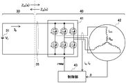
- FIG. 2A is an explanatory diagram of a configuration example of a DC power feeding system whose stability is analyzed by the design support device.
- FIG. 2B is an explanatory diagram of a configuration example of a DC power feeding system whose stability is analyzed by the design support device.
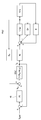
- FIG. 3 is a control block diagram showing the control contents of the q-axis current of the control unit included in the servo device.
- FIG. 4 is an explanatory diagram of LC parallel circuit information.
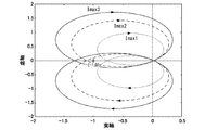
- FIG. 5 is an explanatory diagram of the Nyquist diagram displayed by the design support device.
- FIG. 5 is an explanatory diagram of the Nyquist diagram displayed by the design support device.
- FIG. 6 is a control block diagram showing the control contents of the q-axis current used by the design support device to specify Z D (s) and T(s).
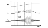
- FIG. 7 is an explanatory diagram of the result of an experiment conducted to confirm that the stability can be analyzed by the design support device.
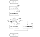
- FIG. 8 is a flowchart of the design support process by the design support device.
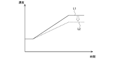
- FIG. 9 is a diagram for explaining the correction processing of the operation pattern initially input by the design support processing.
- FIG. 1 shows a block diagram of a design support device 10 according to an embodiment of the present invention
- FIGS. 2A and 2B show a configuration example of a DC power supply system whose stability is analyzed by the design support device 10.
- the design support apparatus 10 (FIG. 1) according to the present embodiment supports the design of the DC power feeding system by analyzing the stability of the DC power feeding system having the configuration shown in FIGS. 2A and 2B. This is a developed device.
- the DC power feeding system (hereinafter, also referred to as an analysis target system) in which the design support apparatus 10 analyzes stability includes an inverter circuit 41, an electric motor 42, and a control unit.
- This is a system in which electric power from the DC power supply 31 is supplied to one (FIG. 2A) or a plurality (FIG. 2B) of servo devices configured by the unit 43 via the DC bus 35.
- the electric motor 42 of each servo device in the analysis target system is a permanent magnet synchronous electric motor.
- control unit 43 is a unit that controls the q-axis current, as shown in FIG.
- FIG. 3 is a control block diagram showing the control contents of the q-axis current of the control unit 43.
- Kt is a torque constant of the electric motor 42
- K e is an induced voltage constant of the electric motor 42.
- J, Dr, and K are the inertia, viscosity, and spring constant of the mechanical system (the electric motor 42 and the machine driven by the electric motor 42), respectively.
- I q_ref is a reference current (current command)
- I q is a dq-converted current of the electric motor 42 (q-axis current).
- the current compensator 45 is a PI compensator for matching I q with I q_ref .
- the design support device 10 includes an input device 11 such as a keyboard and a mouse, a display 12, and a main body 13.
- the main body 13 is a unit composed of a CPU (Central Processing Unit), a RAM (Random Access Memory), a non-volatile storage device 16 (hard disk drive, solid state drive, etc.) and the like.
- a design support program 18 is installed in the non-volatile storage device 16 of the main body unit 13, and the main body unit 13 reads the design support program 18 into the RAM and executes the program so that the main body unit 13 includes the UI processing unit 14 and the UI processing unit 14. It operates as the stability analysis processing unit 15.
- the UI processing unit 14 is a unit that acquires system information and display target designation information from a user through operations on the input device 11 while displaying various image information on the screen of the display 12.
- the system information acquired by the UI processing unit 14 from the user is information indicating the configuration and operation of the analysis target system.
- the UI processing unit 14 acquires the following information from the user as the system information.
- -LC parallel circuit designation information for handling the power supply side section 30 of the analysis target system as an LC parallel circuit having the configuration shown in FIG. 4-Output voltage V b (DC converter 31 for converting system voltage to DC) (output voltage V b ( Hereinafter, also referred to as DC bus voltage V b )
- Inductance L m of the electric motor 42 of each servo device, armature resistance R m Of-current compensator 45 of the servo device (3) proportional gain K p and the integral gain K i ⁇ Operation pattern information of each servo device
- the operation pattern information of each servo device is a command value group (time-series data of position command, etc.) input to each control unit 43 in order to operate each servo device.
- the use of the motion pattern information will be described later, but the motion pattern information is information that can be omitted.
- LC parallel circuit designation information UI processing unit 14 obtains from the user, the C b in FIG. 4, but including capacitance and DC bus capacitance of the input capacitor of the inverter circuit 41.
- the display target designation information acquired by the UI processing unit 14 from the user is information that designates one or more DC bus currents I b for causing the stability analysis processing unit 15 to display the Nyquist diagram.
- the display target designation information may be information that directly designates one or more DC bus currents I b or information that indirectly designates one or more DC bus currents I b .
- the UI processing unit 14 normally waits for the user to input the above two pieces of information (system information and display target designation information). Then, when the execution instruction of the stability analysis process is input by the user after the input of the two pieces of information, the stability analysis processing unit 15 is instructed to start the stability analysis process.
- the stability analysis processing executed by the stability analysis processing unit 15 is based on the system information, and the output impedance Z o (s) (s is a Laplace operator of the power supply side unit 30 of the analysis target system (FIGS. 2A and 2B). ) And the input impedance Z in (s) of the load side portion 40 of the system to be analyzed, and “Z o (s)/Z in (s)” from the specified Z o (s) and Z in (s). Is a process of displaying (outputting) the Nyquist diagram of No. 1 on the screen of the display 12.
- the stability analysis process is performed by converting the input impedance Z in (s) of the load side 40, s, the DC bus current I b, and the DC bus current I b into the q-axis current of the electric motor 42 by the conversion rate ⁇ . as well as a process using a function has become a process of displaying the Nyquist plot for each DC bus current I b to display target specifying information directly specifies / indirectly.
- the stability analysis processing unit 15 outputs not only the display processing of the Nyquist diagram on the display 12 but also data regarding the Nyquist diagram inside the design support device 10 or outside the device. It may include a process of outputting to another process.
- the stability analysis processing unit 15 calculates the output impedance Z o (s) of the power supply side unit 30 of the analysis target system based on the system information (LC parallel circuit information) according to the following formula (A1). Prepare the represented function.
- the stability analysis processing unit 15 prepares a function that satisfies the following expression (A2) as the input impedance Z in (s) of the load side unit 40 based on the system information (information other than the LC parallel circuit information). ..
- Z N (s) is the input impedance of the servo device during ideal feedback.
- Z D (s) is the input impedance of the servo device when there is no feedback (when there is no feedback)
- T(s) is the loop transfer function of the servo device.
- Z N (s) can be represented by the following formula (B0).
- the input impedance and open loop transfer function of the servo device when I q is not fed back can be obtained from FIG. However, if the functions obtained from FIG. 3 are used as Z D (s) and T(s), the calculation load at the time of displaying the Nyquist diagram becomes large.
- T(s) can be represented by equation (A5).
- the input impedance Z D (s) of the servo device when I q is not fed back becomes an electric time constant part of the electric motor 42.
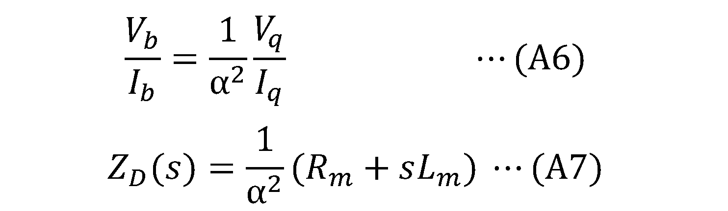
- the input impedance Z D (s) obtained from FIG. 6 is a value on the side of V q and I q . Therefore, stability analysis processing section 15, the following (A6) equation holds for conversion alpha (described later in detail) with the input impedance Z D (s) obtained from FIG. 6, V q, I q
- Z D (s) represented by the following formula (A7) is prepared.
- the stability analysis processing unit 15 when preparing the Z D (s), the stability analysis processing unit 15 according to the present embodiment, when the operation pattern information of each servo device is set, displays the machine information such as inertia related to the servo device. The change pattern of the speed and the current command value is specified based on the set operation pattern information, and the conversion rate ⁇ is calculated from the specified result. Further, when the operation pattern information of each servo device is not set, the stability analysis processing unit 15 calculates the conversion rate ⁇ by the above procedure based on the operation pattern information prepared in advance.
- the stability analysis processing unit 15 that has prepared Z o (s), Z N , Z D (s), and T(s) has Z N , Z D (s), and T(s) (
- the input impedance Z in (s) of the load side portion 40 is prepared from the equation A2).
- the stability analysis processing unit 15 determines, based on the prepared Z in (s) and Z o (s), “Z o for each DC bus current I b directly/indirectly specified by the display target specification information. After displaying the Nyquist diagram of (s)/Z in (s)” on the screen of the display 12, the stability analysis process ends.
- the Nyquist diagram shown in FIG. 5 is obtained by performing the stability analysis process under the conditions according to the actual system.
- K p value and the K i value in the expression (A5) values at which the frequency crossing 0 dB in the Bode diagram of T(s) becomes a predetermined frequency were adopted.
- the Nyquist diagram is displayed under the display conditions in which the maximum currents are Imax1, Imax2, and Imax3 (Imax1 ⁇ Imax2 ⁇ Imax3).
- FIG. 7 shows an experimental result of actually controlling the DC power feeding system in which the L m value, the K p value and the like are the above values.
- the DC bus current I b increases, and when the DC bus current I b increases to about Imax2, the stability determined from the Nyquist diagram shown in FIG. It was confirmed that the DC bus current I b and the DC bus voltage V b started to oscillate according to the sex.
- the design support device 10 (stability analysis processing unit 15) can display the Nyquist diagram corresponding to the actual operation of the DC power feeding system. Therefore, according to the design support device 10, the configuration of the DC power feeding system that is the system information (for example, the specifications of the cable used as the DC cable) and the control content for the inverter circuit 41 are set to make vibration less likely to occur. Is possible.
- the system information may be automatically corrected based on the processing result of the stability analysis processing unit 15 in the design support device 10. Therefore, the correction processing of the system information will be described based on FIG.
- the control according to the flowchart shown in FIG. 8 is executed by the main body 13 of the design support device 10.
- system information is acquired.
- the acquisition process corresponds to a process in which the UI processing unit 14 acquires information about the configuration of the DC bus and operation pattern information about the servo device as system information from the user through an operation on the input device 11.
- stability information of the analysis target system is output.
- the output processing corresponds to processing by the stability analysis processing unit 15 that outputs stability information regarding system stability such as a Nyquist diagram.
- a predetermined stability condition is satisfied based on the stability information output in S102 and the current value required for the operation derived from the operation pattern of each servo device in the analysis target system. Is determined. For example, a description will be given based on the Nyquist diagram which is the output result shown in FIG.
- the predetermined stability condition in this case is the relative positional relationship between the Nyquist diagram and (-1,0).
- the maximum current value derived from the operation pattern is Imax2 or Imax3
- the predetermined stability condition is not satisfied (negative determination).
- the maximum current value is Imax1
- it can be determined that the predetermined stability condition is satisfied affirmmative determination).
- the processing advances to S104, and the system information acquired in S101 is maintained. That is, since the configuration of the DC bus corresponding to the system information acquired in S101 can ensure the stability even in consideration of the system information and the operation pattern of the servo device, it is necessary to correct it. Maintained without.
- the process proceeds to S105, and the system information acquired in S101 is corrected.
- the correction processing corresponds to the processing by the correction means of the present application.
- the modification of the system information for example, the information regarding the configuration of the DC bus may be modified. In this case, the specifications of the DC bus may be appropriately corrected and the correction result may be displayed on the display 12 within a range in which the operation pattern of the servo device can be realized.
- the operation pattern included in the system information may be modified appropriately while the DC bus configuration is maintained as it is, and the modification result may be displayed on the display 12.
- the maximum speed of the servo device is corrected from that shown by line L1 to that shown by line L2, and the correction result is displayed on display 12. ..
- the current value required for the operation of the servo device can be lowered, and a predetermined stability condition can be satisfied.
- the design support device 10 described above can be modified in various ways. For example, if the stability analysis process is transformed into a process for displaying the Bode diagram of Z o (s) and Z in (s) instead of the Nyquist diagram of Z o (s)/Z in (s), good.
- the Bode diagram when the Bode diagram is used, it can be determined that it becomes stable when the magnitude of Z o (s)/Z in (s) is 1 or less or the phase difference is 180 degrees or less. That is, when the gain diagram and the phase diagram of Z o (s) and Z in (s) are as shown in FIG. 10, it can be determined to be stable.
- the stability analysis process may be modified into a process of outputting data (numerical value group) representing the Nyquist diagram or the Bode diagram, instead of the process of displaying the Nyquist diagram or the Bode diagram.
- the stability analysis process may be provided with a function of determining whether it is stable and outputting the determination result.
- some functions may be removed from the design support device 10, and the design support device 10 may be a device that inputs and outputs information via a network (in other words, an input device 11 and a display 12 are provided. It is a matter of course that it may be transformed into a non-apparatus).
- Design support device for supporting the design of a DC power supply system in which power is supplied from a DC power supply (31) to one or more servo devices including an inverter circuit (41) and an electric motor (42) via a DC bus (35).
- An acquisition unit (14) for acquiring system information indicating the configuration of the DC bus of the DC power supply system;
- An output unit that outputs information about the stability of the DC power feeding system based on the system information acquired by the acquisition unit (14) and the current value required for each operation of the one or more servo devices ( 15),
- a design support device (10) comprising:
- Design Support Device 11 Input Device 12 Display 13 Main Body 14 UI Processing Unit 15 Stability Analysis Processing Unit 16 Nonvolatile Storage Unit 18 Design Support Program 30 Power Supply Side 31 DC Power Supply 40 Load Side 41 Inverter 42 Electric Motor 43 Control Section
Landscapes
- Engineering & Computer Science (AREA)
- Physics & Mathematics (AREA)
- Theoretical Computer Science (AREA)
- Geometry (AREA)
- Computer Hardware Design (AREA)
- General Physics & Mathematics (AREA)
- Evolutionary Computation (AREA)
- General Engineering & Computer Science (AREA)
- Computational Mathematics (AREA)
- Mathematical Analysis (AREA)
- Mathematical Optimization (AREA)
- Pure & Applied Mathematics (AREA)
- Inverter Devices (AREA)
- Control Of Electric Motors In General (AREA)
- Control Of Ac Motors In General (AREA)
Abstract
設計支援装置は、DC給電システムのDCバスの構成を示すシステム情報を取得する手段と、取得手段により取得されたシステム情報と、1台以上のサーボ装置のそれぞれの動作に要する電流値とに基づいて、DC給電システムの安定性に関する情報を出力する出力手段と、を備える。この構成により、インバータ回路と電動機とを含む1台以上のサーボ装置に直流電源からDCバスにより電力が供給されるDC給電システムの安定性をDCバスの構成を考慮して解析可能となる。
Description
本発明は、設計支援装置と設計支援方法と設計支援プログラムとに関する。
工場等では、複数の電動機が、離れた場所に配置された複数のサーボドライバにてPWM駆動されるシステム(ロボットとその制御装置とで構成されたシステム等)が使用されている。そのようなシステムには、電動機・サーボドライバ間の長いケーブルからの放射ノイズを低減するために、スイッチングスピードを速くできない、電動機・サーボドライバ間の接続に多数のケーブルが必要とされる、といった問題がある。
各電動機の近傍にサーボドライバ内のインバータ回路のみを配置し、1つの直流電源からDCバスにて複数のインバータ回路に電力を供給する構成を採用しておけば、上記問題が発生しないようにすることが出来る。
ただし、この構成を採用したシステムでは、DCバス側のLC回路とインバータ回路側とが干渉してシステムの動作が不安定となる場合がある(例えば、非特許文献1参照)。実物で配線し発振が確認された場合、実物の配線バスを修正し発振を抑制するので、工数が必要となる。また、発振が抑制できるまで配線バスを試行錯誤的に変える必要があり更に工数を必要とする。そのため、上記構成の採用時には、DCバス側のインダクタンス等を考慮した安定性解析が必要とされる。
横尾 真志, 近藤 圭一郎,「直流電気鉄道車両におけるベクトル制御された誘導電動機駆動システムのダンピング制御系設計法」、電気学会論文誌D,Vol. 135 No.6 pp.622-631(2015)
R. D. Middlebrook, "Input Filter Considerations in Design and Application of Switching Regulators", Proc, IEEE Industrial Application Society Annual Meeting pp.363-382 (1976)
本発明は、上記現状に鑑みなされたものであり、インバータ回路と電動機とを含む1台以上のサーボ装置に直流電源からDCバスにより電力が供給されるDC給電システムの安定性を、DCバスの構成を考慮して解析(評価)可能な技術を提供することを目的とする。
本発明の一観点に係る設計支援装置は、インバータ回路と電動機とを含む1台以上のサーボ装置に直流電源からDCバスにより電力が供給されるDC給電システムの設計を支援する装置である。そして、設計支援装置は、前記DC給電システムの前記DCバスの構成を示すシステム情報を取得する取得手段と、前記取得手段により取得された前記システム情報と、前記1台以上のサーボ装置のそれぞれの動作に要する電流値とに基づいて、前記DC給電システムの安定性に関する情報を出力する出力手段と、を備える。システム情報は、DCバスのハード構成に基づく電気的特性に関連する情報であり、DC給電システムの安定性は、DCバスを流れる作動電流値と強い関係性を有する。そこで、このような構成を有する設計支援装置によれば、DC給電システムの安定性をDCバスの構成と、そこから給電されるサーボ装置での動作電流とを考慮して解析(評価)することが出来る。
そして、前記出力手段は、前記システム情報に応じたZo(s)及びZin(s)(sはラプラス演算子)に基づき、前記DC給電システムの安定性に関する情報を出力するように構成され、そして、前記Zo(s)が、前記DC給電システムを前記1台以上のサーボ装置を含む負荷側部と前記負荷側部に電力を供給する電源側部とを接続した接続システムであると見做した場合における前記電源側部の出力インピーダンスを、sの関数として表した式であり、前記Zin(s)が、前記DC給電システムを前記接続システムであると見做した場合における前記負荷側部の入力インピーダンスを、s、前記DCバスを流れる電流値であるバス電流値及び当該バス電流値の、前記電動機のq軸電流への変換率αの関数として表した式である構成を有する。
すなわち、DC給電システムのDCバスの構成を示すシステム情報があれば、DC給電システムの負荷側部の出力インピーダンスZo(s)を求めることが出来る。また、DC給電システムの電源側部の入力インピーダンスZin(s)は、バス電流値及びバス電流値の、電動機のq軸電流への変換率αの関数として表せる。なお、αの値は、各サーボ装置に入力される指令を仮定するか、当該指令として実際に入力される指令を用いることで算出することが出来る。そして、Zo(s)及びZin(s)から、前記DC給電システムの安定性に関する情報(Zo(s)/Zin(s)のナイキスト線図や、Zo(s)及びZin(s)のボード線図等のDC給電システムが安定性であるか否かを示す情報)を得ることが出来る。従って、設計支援装置によれば、DC給電システムの安定性をDCバスの構成(DCバスのインダクタンス等)を考慮して解析(評価)することが出来る。
設計支援装置の出力手段は、DC給電システムの安定性に関する情報をどのような形で出力するものであっても良い。具体的には、出力手段は、ユーザインターフェースを介して、設計支援装置の外部のユーザ等に対して、前記DC給電システムの安定性に関する情報(ナイキスト線図やボード線図)をディスプレイの画面上に表示するものであっても、ナイキスト線図等を表すデータ(数値群)を出力するものであっても良い。また、これらの情報やデータを、設計支援装置の内部、又は外部の装置で行われる別の処理に対して出力する形態も、上記出力手段による出力形態に含まれる。
設計支援装置の出力手段は、予め設定されているバス電流値毎に、DC給電システムの安定性に関する情報を出力するものであっても、ユーザが指定したバス電流値毎に、DC給電システムの安定性に関する情報を出力するものであっても良い。
設計支援装置の出力手段は、予め設定されているバス電流値毎に、DC給電システムの安定性に関する情報を出力するものであっても、ユーザが指定したバス電流値毎に、DC給電システムの安定性に関する情報を出力するものであっても良い。
出力手段は、前記DC給電システム内の前記サーボ装置が1つである場合の前記Zin (s)を、以下の(1)~(4)式から求めても良い。
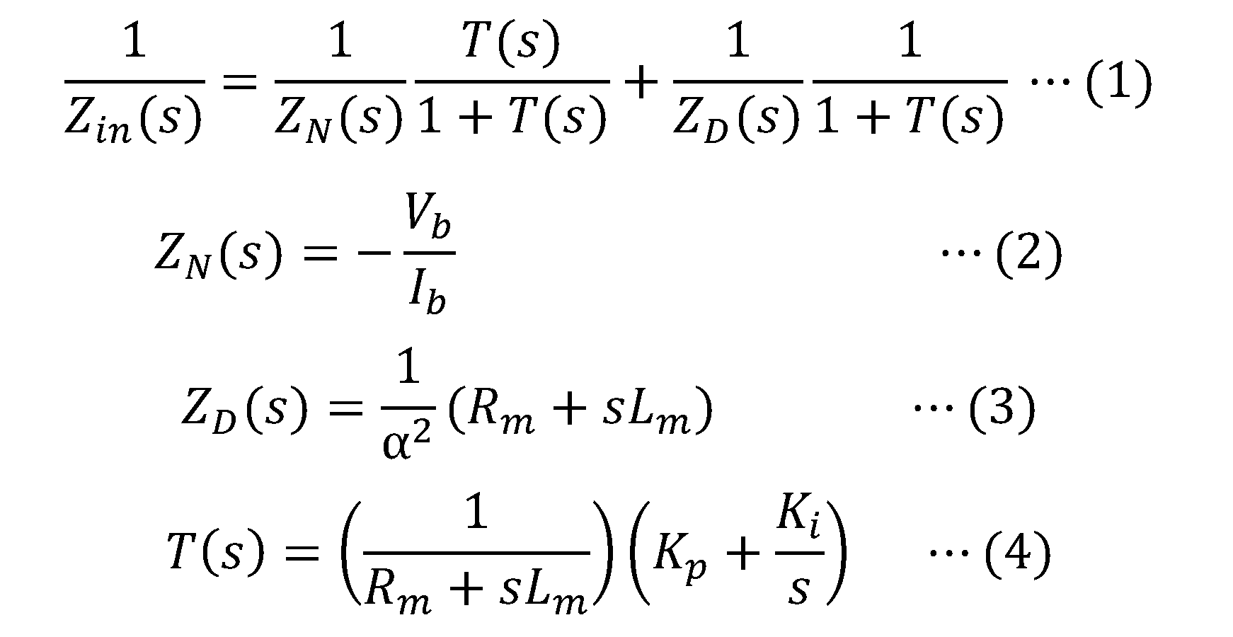
なお、Vb、Ibは、それぞれ、前記DCバスの電圧、電流であり、Rm、Lmは、電動機の抵抗、インダクタンスであり、Kp、Kiは、それぞれ、電動機へのq軸電流を電流指令と一致させるために行われるPI制御の比例ゲイン、積分ゲインである。
ここで、上述までの設計支援装置において、前記システム情報は、前記1台以上のサーボ装置のそれぞれの動作パターンを示す動作パターン情報を含んでもよい。動作パターンを含むことで、その動作パターンに基づいて前記1台以上のサーボ装置のそれぞれの動作に要する電流値に関する情報を導出でき、それを利用して上記の安定性に関する情報を出力することが可能となる。
また、上述までの設計支援装置は、前記出力手段により出力された前記DC給電システムの安定性に関する情報が、所定の安定性条件を満たしていない場合、前記所定の安定性条件を満たすように前記システム情報を修正する修正手段を、更に備えてもよい。このような構成により、修正手段による修正処理を通して、DC給電システムの安定性が所定の安定性条件を満たしたシステム情報を取得することが可能となる。例えば、修正手段は、DCバスの構成の修正を行うことができる。また、別法として、前記システム情報に前記動作パターン情報が含まれる場合であって、前記DC給電システムの安定性に関する情報が前記所定の安定性条件を満たしていない場合には、前記修正手段は、前記1台以上のサーボ装置のそれぞれの動作に要する電流値が下がるように前記動作パターン情報に応じた前記動作パターンを修正することもできる。
また、本発明の一観点に係る、インバータ回路と電動機とを含む1台以上のサーボ装置に直流電源からDCバスにより電力が供給されるDC給電システムの設計を支援する設計支援方法は、前記DC給電システムの前記DCバスの構成を示すシステム情報を取得し、前記システム情報と、前記1台以上のサーボ装置のそれぞれの動作に要する電流値とに基づいて、前記DC給電システムの安定性に関する情報を出力する。更に、当該設計支援方法において、前記システム情報と、前記1台以上のサーボ装置のそれぞれの動作に要する電流値とに基づいて、前記DC給電システムを前記1台以上のサーボ装置を含む負荷側部と前記負荷側部に電力を供給する電源側部とを接続したシステムであると見做して、前記電源側部の出力インピーダンスであるZo(s)を特定すると共に、前記負荷側部の入力インピーダンスであるZin(s)として、前記DCバスを流れる電流値及び当該電流値の、前記電動機のq軸電流への変換率αの関数を特定し、特定したZo(s)及びZin(s)に基づき、DC給電システムの安定性に関する情報を出力する。また、本発明の一観点に係る設計支援プログラムは、コンピュータを、上記したいずれかの構成の設計支援装置として動作させる。従って、これらの技術によっても、DC給電システムの安定性をDCバスの構成(DCバスのインダクタンス等)を考慮して解析(評価)することが可能となる。
本発明によれば、インバータ回路と電動機とを含む1台以上のサーボ装置に直流電源からDCバスにより電力が供給されるDC給電システムの安定性を、DCバスの構成を考慮して解析することが可能となる。
以下、図面を参照して本発明の実施の形態について説明する。
図1に、本発明の一実施形態に係る設計支援装置10のブロック図を示し、図2A及び図2Bに、設計支援装置10により安定性が解析されるDC給電システムの構成例を示す。
本実施形態に係る設計支援装置10(図1)は、図2Aや図2Bに示したような構成のDC給電システムの安定性を解析することで、当該DC給電システムの設計を支援するために開発した装置である。
具体的には、図2A及び図2Bに示してあるように、設計支援装置10が安定性を解析するDC給電システム(以下、解析対象システムとも表記する)は、インバータ回路41、電動機42及び制御部43により構成された1台(図2A)又は複数台(図2B)のサーボ装置に、DCバス35を介して、直流電源31からの電力が供給されるシステムである。
解析対象システム内の各サーボ装置の電動機42は、永久磁石同期電動機である。また、各サーボ装置の制御部43は、電動機42に取り付けられたエンコーダ(図示略)及び電動機42の駆動電流を検知するセンサ(図示略)からの情報(図では、θ、iu、iv)に基づき、非干渉化補償を伴うベクトル制御を、d軸電流Id=0として行うユニットである。
より詳細には、制御部43は、図3に示したように、q軸電流を制御するユニットとなっている。なお、この図3は、制御部43のq軸電流の制御内容を示す制御ブロック図である。また、図3において、Ktは、電動機42のトルク定数であり、Keは、電動機42の誘起電圧定数である。J、Dr、Kは、それぞれ、機械系(電動機42と電動機42にて駆動される機械)のイナーシャ、粘性、ばね定数である。Iq_refは、基準電流(電流指令)であり、Iqは、dq変換した電動機42の電流(q軸電流)である。電流補償器45は、IqをIq_refと一致させるためのPI補償器である。
図1に戻って、設計支援装置10の構成及び機能を説明する。
図示してあるように、設計支援装置10は、キーボード、マウス等の入力装置11と、ディスプレイ12と、本体部13とを備える。
図示してあるように、設計支援装置10は、キーボード、マウス等の入力装置11と、ディスプレイ12と、本体部13とを備える。
本体部13は、CPU(Central Processing Unit)、RAM(Random Access Memory)、不揮発性記憶装置16(ハードディスクドライブ、ソリッドステートドライブ等)等で構成されたユニットである。この本体部13の不揮発性記憶装置16には、設計支援プログラム18がインストールされており、CPUが設計支援プログラム18をRAM上に読み出して実行することで、本体部13は、UI処理部14及び安定性解析処理部15として動作する。
UI処理部14は、ディスプレイ12の画面上に各種画像情報を表示しながら、入力装置11に対する操作を通じて、ユーザから、システム情報及び表示対象指定情報を取得するユニットである。
UI処理部14がユーザから取得するシステム情報は、解析対象システムの構成及び動作を示す情報である。UI処理部14は、このシステム情報として、ユーザから、以下の情報を取得する。
・解析対象システムの電源側部30を、図4に示した構成のLC並列回路として取り扱うためのLC並列回路指定情報
・直流電源31(系統電圧を直流化するコンバータ等)の出力電圧Vb(以下、DCバス電圧Vbとも表記する)
・各サーボ装置の電動機42のインダクタンスLm、電機子抵抗Rm
・各サーボ装置の電流補償器45(図3)の比例ゲインKp及び積分ゲインKi
・各サーボ装置の動作パターン情報
・解析対象システムの電源側部30を、図4に示した構成のLC並列回路として取り扱うためのLC並列回路指定情報
・直流電源31(系統電圧を直流化するコンバータ等)の出力電圧Vb(以下、DCバス電圧Vbとも表記する)
・各サーボ装置の電動機42のインダクタンスLm、電機子抵抗Rm
・各サーボ装置の電流補償器45(図3)の比例ゲインKp及び積分ゲインKi
・各サーボ装置の動作パターン情報
なお、各サーボ装置の動作パターン情報とは、各サーボ装置を動作させるために、各制御部43に入力される指令値群(位置指令の時系列データ等)のことである。動作パターン情報の用途については後述するが、動作パターン情報は、入力を省略できる情報となっている。
UI処理部14がユーザから取得するLC並列回路指定情報は、図4におけるCbに、各インバータ回路41の入力コンデンサの容量及びDCバスの容量を含めたものである。
UI処理部14がユーザから取得する表示対象指定情報は、安定性解析処理部15にナイキスト線図を表示させる1つ以上のDCバス電流Ibを指定する情報である。この表示対象指定情報は、1つ以上のDCバス電流Ibを、直接的に指定する情報であっても、間接的に指定する情報であっても良い。
UI処理部14は、通常は、上記2情報(システム情報と表示対象指定情報)がユーザにより入力されるのを待機している。そして、2情報の入力完了後に、ユーザから安定解析処理の実行指示が入力された場合には、安定性解析処理の開始を安定性解析処理部15に指示する。
安定性解析処理部15が実行する安定性解析処理は、システム情報に基づき、解析対象システム(図2A、図2B)の電源側部30の出力インピーダンスZo(s)(sは、ラプラス演算子)と解析対象システムの負荷側部40の入力インピーダンスZin(s)とを特定し、特定したZo(s)及びZin(s)から“Zo(s)/Zin(s)”のナイキスト線図をディスプレイ12の画面上に表示する(出力する)処理である。また、安定性解析処理は、負荷側部40の入力インピーダンスZin(s)として、sと、DCバス電流Ibと、DCバス電流Ibの、電動機42のq軸電流への変換率αの関数を用いる処理であると共に、表示対象指定情報が直接的/間接的に指定するDCバス電流Ib毎にナイキスト線図を表示する処理となっている。
すなわち、詳細については後述するが、安定性解析処理が行われると、ディスプレイ12の画面上に、例えば、図5に示したようなナイキスト線図が表示される。そのため、ユーザは、各DCバス電流Ibにおけるナイキスト線図(ベクトル軌跡)と、(-1、0)の位置関係から、発振が生ずる/生じないDCバス電流Ibの範囲を把握することが出来る。なお、安定性解析処理部15による出力は、ディスプレイ12への上記ナイキスト線図の表示処理だけではなく、当該ナイキスト線図に関するデータを、設計支援装置10の内部、又はその外部の装置で行われる別の処理に対して出力する形態の処理を含んでもよい。
以下、解析対象システムの負荷側部40が1台のサーボ装置で構成されている場合(図2A)を中心に、安定性解析処理の内容をさらに具体的に説明する。
安定性解析処理時、安定性解析処理部15は、システム情報(LC並列回路情報)に基づき、解析対象システムの電源側部30の出力インピーダンスZo(s)として、以下の(A1)式で表される関数を用意する。


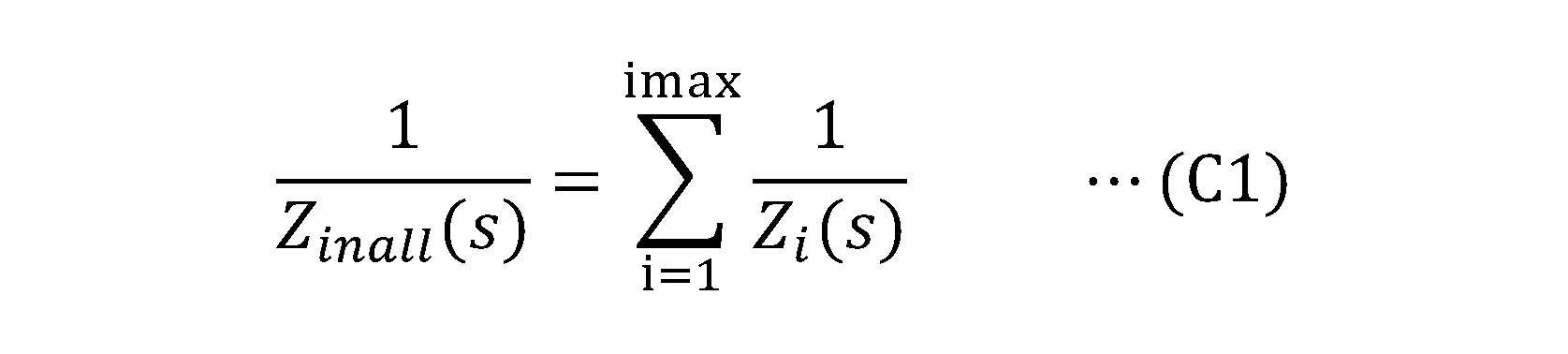
なお、解析対象システムの負荷側部40が複数台のサーボ装置で構成されている場合には、安定性解析処理部15は、(A2)式により用意した各サーボ装置のZin(s)を合成することで、負荷側部40(複数台のサーボ装置全体)の入力インピーダンスZinall(s)を用意することができる。すなわち、安定性解析処理部15は、各サーボ装置が単軸でDCバス35に接続されていると仮定した場合の、その各サーボ装置のZin(s)をZi(s)(i=1~imax)と表記すると、以下の式を満たすZinall(s)を用意することができる。
また、理想フィードバック時におけるサーボ装置の入力インピーダンスは、-Vb/Ibである。すなわち、ZN(s)を、以下の(B0)式で表すことが出来る。

また、サーボ装置においてフィードバックされているのは、Iqである(図3参照)。そのため、ZD(s)、T(s)として、それぞれ、Iqがフィードバックされていない場合におけるサーボ装置の入力インピーダンス、一巡伝達関数を使用すれば良いことになる。
Iqがフィードバックされていない場合におけるサーボ装置の入力インピーダンス、一巡伝達関数は、図3から求めることが出来る。ただし、ZD(s)、T(s)として、図3から求めた関数を用いると、ナイキスト線図表示時の計算負荷が大きくなってしまう。
ここで、サーボ装置の機械系の応答性(通常、数百Hz)が、電源側部30の共振周波数よりもかなり低いことを考えると、H(s)を無視した制御ブロック図、すなわち、図6に示した制御ブロック図から、Iqがフィードバックされていない場合におけるサーボ装置の入力インピーダンス、一巡伝達関数を求めて、ZD(s)、T(s)として使用しても、安定性を良好に評価できることになる。
そして、PI(s)、G(s)は、それぞれ、以下の(A3)式、(A4)式で表すことが出来るため、T(s)を、(A5)式で表せる。

また、Iqがフィードバックされていない場合におけるサーボ装置の入力インピーダンスZD(s)は、電動機42の電気的時定数部分となる。ただし、図6から求められる入力インピーダンスZD(s)は、Vq,Iq側の値となる。そのため、安定性解析処理部15は、変換率αについて成立する以下の(A6)式(詳細は後述)を用いて、図6から求められる入力インピーダンスZD(s)を、Vq,Iq側の値に換算することにより、以下の(A7)式で表されるZD(s)を用意する。なお、本実施形態に係る安定性解析処理部15は、ZD(s)を用意する際、各サーボ装置の動作パターン情報が設定されている場合には、サーボ装置に関するイナーシャ等の機械情報を用い、設定されている動作パターン情報に基づき、速度、電流指令値の変化パターンを特定し、特定結果から変換率αを算出する。また、安定性解析処理部15は、各サーボ装置の動作パターン情報が設定されていない場合には、予め用意されている動作パターン情報に基づき、上記手順で、変換率αを算出する。
以上のようにしてZo(s)、ZN,ZD(s)、T(s)を用意した安定性解析処理部15は、ZN,ZD(s)及びT(s)と(A2)式とから、負荷側部40(1台のサーボ装置)の入力インピーダンスZin(s)を用意する。そして、安定性解析処理部15は、用意したZin(s)及びZo(s)に基づき、表示対象指定情報が直接的/間接的に指定するDCバス電流Ib毎に、“Zo(s)/Zin(s)”のナイキスト線図をディスプレイ12の画面上に表示してから、安定性解析処理を終了する。
以下、幾つかの事項について補足する。
図5に示したナイキスト線図は、実際のシステムに則した条件で安定性解析処理を行うことにより得られたものである。なお、(A5)式のKp値及びKi値としては、T(s)のボード線図における0dBを横切る周波数が所定の周波数となる値を採用した。当該ナイキスト線図は、最大電流をImax1、Imax2、Imax3(Imax1<Imax2<Imax3)とした表示条件で表示されたものである。
図5に示したナイキスト線図は、実際のシステムに則した条件で安定性解析処理を行うことにより得られたものである。なお、(A5)式のKp値及びKi値としては、T(s)のボード線図における0dBを横切る周波数が所定の周波数となる値を採用した。当該ナイキスト線図は、最大電流をImax1、Imax2、Imax3(Imax1<Imax2<Imax3)とした表示条件で表示されたものである。
図7に、Lm値、Kp値等が上記値であるDC給電システムを実際に制御した実験結果を示す。
図7から明らかなように、速度が上昇するにつれ、DCバス電流Ibが増加していき、DCバス電流IbがImax2程度まで上昇すると、図5に示したナイキスト線図から判定される安定性通りに、DCバス電流Ib及びDCバス電圧Vbが発振し始めることが確認できた。
図7から明らかなように、速度が上昇するにつれ、DCバス電流Ibが増加していき、DCバス電流IbがImax2程度まで上昇すると、図5に示したナイキスト線図から判定される安定性通りに、DCバス電流Ib及びDCバス電圧Vbが発振し始めることが確認できた。
このように、設計支援装置10(安定性解析処理部15)は、DC給電システムの実際の動作と対応するナイキスト線図を表示することが出来る。従って、設計支援装置10によれば、システム情報であるDC給電システムの構成(例えば、DCケーブルとして使用するケーブルの仕様)やインバータ回路41に対する制御内容を、振動がより発生しにくいものとすることが可能となる。
また、別法として、設計支援装置10での安定性解析処理部15の処理結果に基づいて、システム情報の修正を自動的に行ってもよい。そこで、システム情報の修正処理について、図8に基づいて説明する。図8に示すフローチャートに従う制御は、設計支援装置10の本体部13によって実行される。先ず、S101では、システム情報の取得が行われる。当該取得処理は、入力装置11に対する操作を通じて、ユーザから、UI処理部14がシステム情報として、DCバスの構成に関する情報やサーボ装置の動作パターン情報を取得する処理に相当する。続いて、S102では、解析対象システムの安定性情報の出力が行われる。当該出力処理は、安定性解析処理部15によるナイキスト線図等のシステムの安定性に関する安定性情報を出力する処理に相当する。
そして、S103では、S102で出力された安定性情報と、解析対象システムにおいて、各サーボ装置の動作パターンから導出される、その動作に必要な電流値とに基づいて、所定の安定性条件を満たしているか否かが判定される。例えば、図5に示す出力結果であるナイキスト線図に基づいて説明する。この場合の所定の安定性条件とは、ナイキスト線図と(-1,0)との相対位置関係となる。ここで、動作パターンから導出される最大の電流値がImax2やImax3である場合には、所定の安定性条件を満たしていないと判断できる(否定判定)。一方で、最大の電流値がImax1である場合には、所定の安定性条件を満たしていると判断できる(肯定判定)。
そこで、S103で肯定判定された場合には、処理はS104へ進み、S101で取得されたシステム情報は維持される。すなわち、S101で取得されたシステム情報に対応するDCバスの構成は、当該システム情報とサーボ装置の動作パターンを考慮しても安定性を確保することができるものであるから、それを修正する必要は無く維持される。一方で、S103で否定判定された場合には、処理はS105へ進み、S101で取得されたシステム情報が修正される。当該修正処理が、本願の修正手段による処理に相当する。システム情報の修正については、一例としては、DCバスの構成に関する情報を修正してもよい。この場合、サーボ装置の動作パターンを実現可能な範囲において、DCバスの諸元を適宜修正し、その修正結果をディスプレイ12に表示してもよい。
また、システム情報の修正の別例として、DCバスの構成はそのままに維持した上で、システム情報に含まれる動作パターンを適宜修正して、その修正結果をディスプレイ12に表示してもよい。例えば、図9に示すように、S101で取得された動作パターン情報のうち、サーボ装置の最高速度を線L1で示すものから線L2で示すものに修正し、その修正結果をディスプレイ12に表示する。このように最高速度を低下させることで、サーボ装置の作動に要する電流値を低くすることができ、所定の安定性条件を満たすことが可能となる。
なお、システム情報が修正された場合、その修正結果の受け入れは、入力装置11を介してユーザが適宜決定すればよい。
最後に、上記した(A6)式が成立する理由を説明しておくことにする。
DCバス電圧VbとDCバス電流Ibとd軸電圧Vdとd軸電流Idとq軸電圧Vqとq軸電流Iqとの間には、以下の(B1)式が成立する。そして、Id=0であるため、(B1)式を以下の(B2)式に変形することが出来る。
DCバス電圧VbとDCバス電流Ibとd軸電圧Vdとd軸電流Idとq軸電圧Vqとq軸電流Iqとの間には、以下の(B1)式が成立する。そして、Id=0であるため、(B1)式を以下の(B2)式に変形することが出来る。
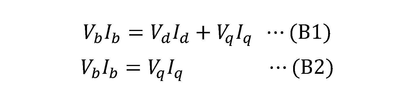
(B2)式から、DCバス電流Ibとq軸電流Iqの比である変換率αについて、以下の(B3)式が成立する。従って、以下の(B4)式、すなわち、上記した(A6)式が成立することになる。

《変形形態》
上記した設計支援装置10は、各種の変形が可能なものである。例えば,安定性解析処理を、Zo(s)/Zin(s)のナイキスト線図ではなく、Zo(s)及びZin(s)のボード線図を表示する処理に変形しても良い。なお、ボード線図を用いる場合には、Zo(s)/Zin(s)の大きさが1以下または位相が180度以下の位相差であるときに安定となると判定することが出来る。すなわち、Zo(s)及びZin(s)のゲイン線図や位相線図が図10に示したようなものであるときに、安定となると判定することが出来る。また、安定性解析処理を、ナイキスト線図やボード線図を表示する処理ではなく、ナイキスト線図やボード線図を表すデータ(数値群)を出力する処理に変形しても良い。安定性解析処理を、そのような処理に変形する場合には、安定性解析処理に、安定であるか否かを判定して判定結果を出力する機能を付与しておいても良い。また、設計支援装置10から幾つかの機能を取り除いておいても良いことや、設計支援装置10を、ネットワークを介して情報を入出力する装置(換言すれば、入力装置11、ディスプレイ12を備えない装置)に変形しても良いことは、当然のことである。
上記した設計支援装置10は、各種の変形が可能なものである。例えば,安定性解析処理を、Zo(s)/Zin(s)のナイキスト線図ではなく、Zo(s)及びZin(s)のボード線図を表示する処理に変形しても良い。なお、ボード線図を用いる場合には、Zo(s)/Zin(s)の大きさが1以下または位相が180度以下の位相差であるときに安定となると判定することが出来る。すなわち、Zo(s)及びZin(s)のゲイン線図や位相線図が図10に示したようなものであるときに、安定となると判定することが出来る。また、安定性解析処理を、ナイキスト線図やボード線図を表示する処理ではなく、ナイキスト線図やボード線図を表すデータ(数値群)を出力する処理に変形しても良い。安定性解析処理を、そのような処理に変形する場合には、安定性解析処理に、安定であるか否かを判定して判定結果を出力する機能を付与しておいても良い。また、設計支援装置10から幾つかの機能を取り除いておいても良いことや、設計支援装置10を、ネットワークを介して情報を入出力する装置(換言すれば、入力装置11、ディスプレイ12を備えない装置)に変形しても良いことは、当然のことである。
《付記1》
インバータ回路(41)と電動機(42)とを含む1台以上のサーボ装置にDCバス(35)を介して直流電源(31)から電力が供給されるDC給電システムの設計を支援する設計支援装置(10)であって、
前記DC給電システムの前記DCバスの構成を示すシステム情報を取得する取得手段(14)と、
前記取得手段(14)により取得された前記システム情報と、前記1台以上のサーボ装置のそれぞれの動作に要する電流値とに基づいて、前記DC給電システムの安定性に関する情報を出力する出力手段(15)と、
を備える、設計支援装置(10)。
インバータ回路(41)と電動機(42)とを含む1台以上のサーボ装置にDCバス(35)を介して直流電源(31)から電力が供給されるDC給電システムの設計を支援する設計支援装置(10)であって、
前記DC給電システムの前記DCバスの構成を示すシステム情報を取得する取得手段(14)と、
前記取得手段(14)により取得された前記システム情報と、前記1台以上のサーボ装置のそれぞれの動作に要する電流値とに基づいて、前記DC給電システムの安定性に関する情報を出力する出力手段(15)と、
を備える、設計支援装置(10)。
10 設計支援装置
11 入力装置
12 ディスプレイ
13 本体部
14 UI処理部
15 安定性解析処理部
16 不揮発性記憶部
18 設計支援プログラム
30 電源側部
31 直流電源
40 負荷側部
41 インバータ
42 電動機
43 制御部
11 入力装置
12 ディスプレイ
13 本体部
14 UI処理部
15 安定性解析処理部
16 不揮発性記憶部
18 設計支援プログラム
30 電源側部
31 直流電源
40 負荷側部
41 インバータ
42 電動機
43 制御部
Claims (11)
- インバータ回路と電動機とを含む1台以上のサーボ装置にDCバスを介して直流電源から電力が供給されるDC給電システムの設計を支援する設計支援装置であって、
前記DC給電システムの前記DCバスの構成を示すシステム情報を取得する取得手段と、
前記取得手段により取得された前記システム情報と、前記1台以上のサーボ装置のそれぞれの動作に要する電流値とに基づいて、前記DC給電システムの安定性に関する情報を出力する出力手段と、
を備える、設計支援装置。 - 前記出力手段は、前記システム情報に応じたZo(s)及びZin(s)(sはラプラス演算子)に基づき、前記DC給電システムの安定性に関する情報を出力し、
前記Zo(s)が、前記DC給電システムを前記1台以上のサーボ装置を含む負荷側部と前記負荷側部に電力を供給する電源側部とを接続した接続システムであると見做した場合における前記電源側部の出力インピーダンスを、sの関数として表した式であり、
前記Zin(s)が、前記DC給電システムを前記接続システムであると見做した場合における前記負荷側部の入力インピーダンスを、s、前記DCバスを流れる電流値であるバス電流値及び当該バス電流値の、前記電動機のq軸電流への変換率αの関数として表した式である、
請求項1に記載の設計支援装置。 - 前記システム情報は、前記1台以上のサーボ装置のそれぞれの動作パターンを示す動作パターン情報を含む、
請求項1又は請求項2に記載の設計支援装置。 - 前記出力手段により出力された前記DC給電システムの安定性に関する情報が、所定の安定性条件を満たしていない場合、前記所定の安定性条件を満たすように前記システム情報を修正する修正手段を、更に備える、
請求項1から請求項3の何れか1項に記載の設計支援装置。 - 前記システム情報に前記動作パターン情報が含まれる場合であって、前記DC給電システムの安定性に関する情報が前記所定の安定性条件を満たしていない場合には、前記修正手段は、前記1台以上のサーボ装置のそれぞれの動作に要する電流値が下がるように前記動作パターン情報に応じた前記動作パターンを修正する、
請求項4に記載の設計支援装置。 - 前記出力手段は、“Zo(s)/Zin(s)”のナイキスト線図を出力する、
ことを特徴とする請求項1から請求項5の何れか1項に記載の設計支援装置。 - 前記出力手段は、Zo(s)及びZin(s)のボード線図を出力する、
ことを特徴とする請求項1から請求項5の何れか1項に記載の設計支援装置。 - 前記出力手段は、前記DC給電システム内の前記サーボ装置が1つである場合の前記Zin(s)を、以下の(1)~(4)式から求める、
ことを特徴とする請求項1から7のいずれか一項に記載の設計支援装置。

- インバータ回路と電動機とを含む1台以上のサーボ装置に直流電源からDCバスにより電力が供給されるDC給電システムの設計を支援する設計支援方法において、
前記DC給電システムの前記DCバスの構成を示すシステム情報を取得し、
前記システム情報と、前記1台以上のサーボ装置のそれぞれの動作に要する電流値とに基づいて、前記DC給電システムの安定性に関する情報を出力する、
設計支援方法。 - 前記システム情報と、前記1台以上のサーボ装置のそれぞれの動作に要する電流値とに基づいて、前記DC給電システムを前記1台以上のサーボ装置を含む負荷側部と前記負荷側部に電力を供給する電源側部とを接続したシステムであると見做して、前記電源側部の出力インピーダンスであるZo(s)(sはラプラス演算子)を特定すると共に、前記負荷側部の入力インピーダンスであるZin(s)として、前記DCバスを流れる電流値と当該電流値の、前記電動機のq軸電流への変換率αの関数を特定し、
特定した前記Zo(s)及び前記Zin(s)に基づき、前記DC給電システムの安定性に関する情報を出力する、
請求項9に記載の設計支援方法。 - コンピュータを、請求項1から8のいずれか一項に記載の設計支援装置として動作させる設計支援プログラム。
Priority Applications (4)
| Application Number | Priority Date | Filing Date | Title |
|---|---|---|---|
| US17/419,461 US20220004676A1 (en) | 2019-01-24 | 2020-01-24 | Design assistance device, design assistance method, and design assistance program |
| DE112020000515.1T DE112020000515T5 (de) | 2019-01-24 | 2020-01-24 | Konstruktionsunterstützungsvorrichtung, konstruktionsunterstützungsverfahren und konstruktionsunterstützungsprogramm |
| CN202080007713.4A CN113261002B (zh) | 2019-01-24 | 2020-01-24 | 设计辅助装置、设计辅助方法以及存储介质 |
| JP2020567723A JP7215499B2 (ja) | 2019-01-24 | 2020-01-24 | 設計支援装置、設計支援方法及び設計支援プログラム |
Applications Claiming Priority (2)
| Application Number | Priority Date | Filing Date | Title |
|---|---|---|---|
| JP2019-010567 | 2019-01-24 | ||
| JP2019010567 | 2019-01-24 |
Publications (1)
| Publication Number | Publication Date |
|---|---|
| WO2020153488A1 true WO2020153488A1 (ja) | 2020-07-30 |
Family
ID=71736964
Family Applications (1)
| Application Number | Title | Priority Date | Filing Date |
|---|---|---|---|
| PCT/JP2020/002574 Ceased WO2020153488A1 (ja) | 2019-01-24 | 2020-01-24 | 設計支援装置、設計支援方法及び設計支援プログラム |
Country Status (5)
| Country | Link |
|---|---|
| US (1) | US20220004676A1 (ja) |
| JP (1) | JP7215499B2 (ja) |
| CN (1) | CN113261002B (ja) |
| DE (1) | DE112020000515T5 (ja) |
| WO (1) | WO2020153488A1 (ja) |
Cited By (4)
| Publication number | Priority date | Publication date | Assignee | Title |
|---|---|---|---|---|
| JP2020120573A (ja) * | 2019-01-24 | 2020-08-06 | オムロン株式会社 | 設計支援装置、設計支援方法及び設計支援プログラム |
| WO2022190532A1 (ja) * | 2021-03-12 | 2022-09-15 | オムロン株式会社 | 検査装置、検査方法及びプログラム |
| JP2022140909A (ja) * | 2021-03-15 | 2022-09-29 | オムロン株式会社 | 電力制御システム、電力供給方法、プログラム |
| WO2023067787A1 (ja) * | 2021-10-22 | 2023-04-27 | ファナック株式会社 | 安定余裕の設定支援装置、制御システム及び設定支援方法 |
Citations (1)
| Publication number | Priority date | Publication date | Assignee | Title |
|---|---|---|---|---|
| JP2015019566A (ja) * | 2013-07-10 | 2015-01-29 | ザ・ボーイング・カンパニーTheBoeing Company | 電力システムの安定性 |
Family Cites Families (8)
| Publication number | Priority date | Publication date | Assignee | Title |
|---|---|---|---|---|
| US5198698A (en) * | 1991-02-11 | 1993-03-30 | Best Power Technology, Inc. | Auxiliary power supply system for providing dc power on demand |
| US7506179B2 (en) * | 2003-04-11 | 2009-03-17 | Zilker Labs, Inc. | Method and apparatus for improved DC power delivery management and configuration |
| CA2641657A1 (en) * | 2006-02-14 | 2007-08-23 | Edsa Micro Corporation | Systems and methods for real-time system monitoring and predictive analysis |
| JP5801999B2 (ja) * | 2010-08-24 | 2015-10-28 | 株式会社日立製作所 | 鉄道用車上電気機器を搭載した鉄道車両の編成列車 |
| JP5340514B1 (ja) * | 2013-01-11 | 2013-11-13 | 三菱電機株式会社 | エネルギアシストシステム選定支援装置、容量選定装置、消費電力計算装置、及びレイアウト生成装置 |
| US9938119B2 (en) * | 2013-07-26 | 2018-04-10 | Electronic Power Design, Inc. | Method and apparatus for retrofitting a pedestal crane |
| WO2017033320A1 (ja) * | 2015-08-26 | 2017-03-02 | 三菱電機株式会社 | 電源回生コンバータおよびモータ制御装置 |
| CN105119265B (zh) * | 2015-09-06 | 2018-01-05 | 南方电网科学研究院有限责任公司 | 辐射状直流电网稳定性判断方法及系统 |
-
2020
- 2020-01-24 DE DE112020000515.1T patent/DE112020000515T5/de active Pending
- 2020-01-24 US US17/419,461 patent/US20220004676A1/en active Pending
- 2020-01-24 WO PCT/JP2020/002574 patent/WO2020153488A1/ja not_active Ceased
- 2020-01-24 JP JP2020567723A patent/JP7215499B2/ja active Active
- 2020-01-24 CN CN202080007713.4A patent/CN113261002B/zh active Active
Patent Citations (1)
| Publication number | Priority date | Publication date | Assignee | Title |
|---|---|---|---|---|
| JP2015019566A (ja) * | 2013-07-10 | 2015-01-29 | ザ・ボーイング・カンパニーTheBoeing Company | 電力システムの安定性 |
Non-Patent Citations (1)
| Title |
|---|
| NAGANO, TSUYOSHI ET AL.: "Investigation of the stability of the damping control and the output power of the auxiliary inverter for Multi-parallelMotor Drive System of Permanent Magnet Synchronous Motors", IEE JAPAN INDUSTRY APPLICATIONS SOCIETY CONFERENCE, 28 August 2013 (2013-08-28), pages 1 - 4 * |
Cited By (10)
| Publication number | Priority date | Publication date | Assignee | Title |
|---|---|---|---|---|
| JP2020120573A (ja) * | 2019-01-24 | 2020-08-06 | オムロン株式会社 | 設計支援装置、設計支援方法及び設計支援プログラム |
| JP7420347B2 (ja) | 2019-01-24 | 2024-01-23 | オムロン株式会社 | 設計支援装置、設計支援方法及び設計支援プログラム |
| WO2022190532A1 (ja) * | 2021-03-12 | 2022-09-15 | オムロン株式会社 | 検査装置、検査方法及びプログラム |
| JP2022139562A (ja) * | 2021-03-12 | 2022-09-26 | オムロン株式会社 | 検査装置、検査方法及びプログラム |
| JP7571632B2 (ja) | 2021-03-12 | 2024-10-23 | オムロン株式会社 | 検査装置、検査方法及びプログラム |
| JP2022140909A (ja) * | 2021-03-15 | 2022-09-29 | オムロン株式会社 | 電力制御システム、電力供給方法、プログラム |
| JP7608893B2 (ja) | 2021-03-15 | 2025-01-07 | オムロン株式会社 | 電力制御システム、電力供給方法、プログラム |
| WO2023067787A1 (ja) * | 2021-10-22 | 2023-04-27 | ファナック株式会社 | 安定余裕の設定支援装置、制御システム及び設定支援方法 |
| JPWO2023067787A1 (ja) * | 2021-10-22 | 2023-04-27 | ||
| JP7741190B2 (ja) | 2021-10-22 | 2025-09-17 | ファナック株式会社 | 安定余裕の設定支援装置、制御システム及び設定支援方法 |
Also Published As
| Publication number | Publication date |
|---|---|
| JP7215499B2 (ja) | 2023-01-31 |
| JPWO2020153488A1 (ja) | 2021-11-11 |
| CN113261002B (zh) | 2024-07-19 |
| CN113261002A (zh) | 2021-08-13 |
| US20220004676A1 (en) | 2022-01-06 |
| DE112020000515T5 (de) | 2021-10-07 |
Similar Documents
| Publication | Publication Date | Title |
|---|---|---|
| JP7215499B2 (ja) | 設計支援装置、設計支援方法及び設計支援プログラム | |
| JP4883151B2 (ja) | 回転機の制御装置 | |
| JP6326832B2 (ja) | インバータ制御方法および電圧型インバータ | |
| CN105027425B (zh) | 控制装置和映射文件变换装置 | |
| JP3754092B2 (ja) | インバータ装置 | |
| JP7420347B2 (ja) | 設計支援装置、設計支援方法及び設計支援プログラム | |
| JP7499875B2 (ja) | 電力変換装置 | |
| JPWO2020217879A1 (ja) | 電力変換装置、機械学習器、および学習済みモデルの生成方法 | |
| CN113206626A (zh) | 一种三相永磁同步电机的控制方法、装置、设备及介质 | |
| JP4727291B2 (ja) | ブロック線図型シミュレーションモデル作成装置、リアルタイムシミュレーション実行装置、及び、ライブラリ | |
| EP4042558B1 (en) | Systems and methods for controlling stepping motor | |
| WO2019138598A1 (en) | Motor drive and method for controlling operation of induction motor | |
| Diab | Real-time implementation of full-order observer for speed sensorless vector control of induction motor drive | |
| CN115913037A (zh) | 一种交流励磁系统的电流调节器的设计方法及装置 | |
| Chebaani et al. | Sensorless finite-state predictive torque control of induction motor fed by four-switch inverter using extended Kalman filter | |
| US20200067439A1 (en) | System and method for improving drive efficiency in an industrial automation system | |
| Jeong et al. | Model predictive current control with modified discrete space vector modulation for three-leg two-phase VSI | |
| CN118694240A (zh) | 直流电机矢量控制系统中的开环控制方法 | |
| JP6991061B2 (ja) | 電源電圧波形算出方法、回路連成磁界解析方法、プログラム及びプログラムを記録した記録媒体 | |
| Choi et al. | Synchronous frame phase compensation for applying modulated model predictive control to high-speed motors | |
| JP2015027136A (ja) | インバータ制御装置 | |
| CN107124129A (zh) | 一种在线辨识感应电机全参数的方法 | |
| JP2022184420A (ja) | 交流電動機の制御装置および制御方法 | |
| JP6222369B2 (ja) | 電動機の駆動制御を行う駆動装置の試験を行うための試験装置 | |
| CN112928961A (zh) | 一种机器人关节电机的电流环优化方法及装置 |
Legal Events
| Date | Code | Title | Description |
|---|---|---|---|
| 121 | Ep: the epo has been informed by wipo that ep was designated in this application |
Ref document number: 20744253 Country of ref document: EP Kind code of ref document: A1 |
|
| ENP | Entry into the national phase |
Ref document number: 2020567723 Country of ref document: JP Kind code of ref document: A |
|
| 122 | Ep: pct application non-entry in european phase |
Ref document number: 20744253 Country of ref document: EP Kind code of ref document: A1 |