WO2020153323A1 - 複合ケーブル、ワイヤハーネスの配索構造、及び複合ケーブルの製造方法 - Google Patents
複合ケーブル、ワイヤハーネスの配索構造、及び複合ケーブルの製造方法 Download PDFInfo
- Publication number
- WO2020153323A1 WO2020153323A1 PCT/JP2020/001836 JP2020001836W WO2020153323A1 WO 2020153323 A1 WO2020153323 A1 WO 2020153323A1 JP 2020001836 W JP2020001836 W JP 2020001836W WO 2020153323 A1 WO2020153323 A1 WO 2020153323A1
- Authority
- WO
- WIPO (PCT)
- Prior art keywords
- composite cable
- linear body
- tubular body
- linear
- composite
- Prior art date
- Legal status (The legal status is an assumption and is not a legal conclusion. Google has not performed a legal analysis and makes no representation as to the accuracy of the status listed.)
- Ceased
Links
Images










Classifications
-
- G—PHYSICS
- G02—OPTICS
- G02B—OPTICAL ELEMENTS, SYSTEMS OR APPARATUS
- G02B6/00—Light guides; Structural details of arrangements comprising light guides and other optical elements, e.g. couplings
- G02B6/44—Mechanical structures for providing tensile strength and external protection for fibres, e.g. optical transmission cables
-
- H—ELECTRICITY
- H01—ELECTRIC ELEMENTS
- H01B—CABLES; CONDUCTORS; INSULATORS; SELECTION OF MATERIALS FOR THEIR CONDUCTIVE, INSULATING OR DIELECTRIC PROPERTIES
- H01B11/00—Communication cables or conductors
- H01B11/22—Cables including at least one electrical conductor together with optical fibres
-
- H—ELECTRICITY
- H01—ELECTRIC ELEMENTS
- H01B—CABLES; CONDUCTORS; INSULATORS; SELECTION OF MATERIALS FOR THEIR CONDUCTIVE, INSULATING OR DIELECTRIC PROPERTIES
- H01B13/00—Apparatus or processes specially adapted for manufacturing conductors or cables
-
- H—ELECTRICITY
- H01—ELECTRIC ELEMENTS
- H01B—CABLES; CONDUCTORS; INSULATORS; SELECTION OF MATERIALS FOR THEIR CONDUCTIVE, INSULATING OR DIELECTRIC PROPERTIES
- H01B13/00—Apparatus or processes specially adapted for manufacturing conductors or cables
- H01B13/012—Apparatus or processes specially adapted for manufacturing conductors or cables for manufacturing wire harnesses
-
- H—ELECTRICITY
- H01—ELECTRIC ELEMENTS
- H01B—CABLES; CONDUCTORS; INSULATORS; SELECTION OF MATERIALS FOR THEIR CONDUCTIVE, INSULATING OR DIELECTRIC PROPERTIES
- H01B7/00—Insulated conductors or cables characterised by their form
-
- H—ELECTRICITY
- H01—ELECTRIC ELEMENTS
- H01B—CABLES; CONDUCTORS; INSULATORS; SELECTION OF MATERIALS FOR THEIR CONDUCTIVE, INSULATING OR DIELECTRIC PROPERTIES
- H01B7/00—Insulated conductors or cables characterised by their form
- H01B7/04—Flexible cables, conductors, or cords, e.g. trailing cables
-
- H—ELECTRICITY
- H01—ELECTRIC ELEMENTS
- H01B—CABLES; CONDUCTORS; INSULATORS; SELECTION OF MATERIALS FOR THEIR CONDUCTIVE, INSULATING OR DIELECTRIC PROPERTIES
- H01B7/00—Insulated conductors or cables characterised by their form
- H01B7/08—Flat or ribbon cables
-
- H—ELECTRICITY
- H01—ELECTRIC ELEMENTS
- H01B—CABLES; CONDUCTORS; INSULATORS; SELECTION OF MATERIALS FOR THEIR CONDUCTIVE, INSULATING OR DIELECTRIC PROPERTIES
- H01B7/00—Insulated conductors or cables characterised by their form
- H01B7/17—Protection against damage caused by external factors, e.g. sheaths or armouring
- H01B7/18—Protection against damage caused by wear, mechanical force or pressure; Sheaths; Armouring
- H01B7/24—Devices affording localised protection against mechanical force or pressure
-
- H—ELECTRICITY
- H02—GENERATION; CONVERSION OR DISTRIBUTION OF ELECTRIC POWER
- H02G—INSTALLATION OF ELECTRIC CABLES OR LINES, OR OF COMBINED OPTICAL AND ELECTRIC CABLES OR LINES
- H02G3/00—Installations of electric cables or lines or protective tubing therefor in or on buildings, equivalent structures or vehicles
- H02G3/02—Details
- H02G3/04—Protective tubing or conduits, e.g. cable ladders or cable troughs
Definitions
- the present invention relates to a composite cable, a wiring harness wiring structure, and a method for manufacturing the composite cable, for example, a vehicle-mounted composite cable, a wiring harness wiring structure, and a method for manufacturing the composite cable.
- Patent Document 1 discloses a vehicle-mounted composite cable in which a tensile strength fiber group having a layer of a conductive material formed on the surface by plating or the like is filled between an optical fiber and its coating.
- Patent Document 2 discloses an indoor composite cable in which a power supply line and a communication line are combined.
- the conventional composite cable has sufficient performance as a vehicle-mounted wire harness.
- the conductive tensile strength fiber constituting the composite cable disclosed in Patent Document 1 is formed by plating a conductive metal such as copper on the surface of the tensile strength fiber such as aramid. Therefore, in order to secure the sufficient conductive performance (electrical resistance) required for a vehicle wiring harness, a conductor cross-sectional area equivalent to that of conventional insulated wires is required, and its bending performance is also equivalent to that of conventional insulated wires. It is considered to be. That is, in the technique described in Patent Document 1, the diameter of the composite cable is larger than that in the case of using a conventional insulated wire in order to satisfy the conductive performance required for a vehicle-mounted wire harness. As a result, the bending performance of the composite cable may be reduced and the weight of the composite cable may be increased.
- the hollow tube is located at the end of the cross section of the composite cable, and only the hollow tube may be affected by the external force. Further, the hollow tube may be locally deformed by the influence of an external force and press the optical code, which may increase the transmission loss of the optical code or break the optical code.
- the composite cable is used as a wire harness
- the number of bending portions with a small bending radius increases, and the above-mentioned hollow tube is likely to be locally deformed (buckling or the like). Therefore, it is hard to say that the bending performance is high.
- the conventional composite cable has sufficient performance as a wire harness.
- the present invention has been made in view of the above-mentioned problems, and an object thereof is to provide a composite cable having sufficient performance as a wire harness.
- a composite cable includes at least one first linear body including a conductor formed of a conductive material, and a tubular shape extending in the extending direction of the first linear body.
- the first linear body and the tubular body are arranged side by side in an arrangement direction that is one direction of a cross section perpendicular to the extending direction of the first linear body.
- the first linear body and the outer cover are configured to be capable of suppressing local deformation of the tubular body due to the influence of an external force.
- the composite cable of the present invention it is possible to provide a composite cable having sufficient performance as a wire harness.
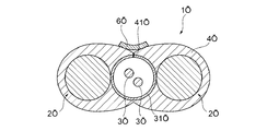
- FIG. 3 is a cross-sectional view of the composite cable according to the first embodiment. It is sectional drawing of the optical fiber core wire as a signal wire.
- 7 is a cross-sectional view of a composite cable according to a second embodiment.
- FIG. 7 is a sectional view of a composite cable according to a third embodiment. It is sectional drawing of the composite cable which concerns on Embodiment 4. It is sectional drawing of the composite cable which concerns on Embodiment 5. It is sectional drawing of the composite cable which concerns on Embodiment 6. It is sectional drawing of the composite cable which concerns on Embodiment 7. It is sectional drawing of the composite cable which concerns on Embodiment 8. It is sectional drawing of the composite cable which concerns on Embodiment 9.
- FIG. 6 is a cross-sectional view showing another aspect of the composite cable according to the first embodiment.
- FIG. 6 is a cross-sectional view showing still another aspect of the composite cable according to the first embodiment.
- FIG. 7 is a cross-sectional view showing another aspect of the composite cable according to the second embodiment.
- FIG. 16 is a cross-sectional view showing another aspect of the composite cable according to the fifth embodiment.
- FIG. 6 is a cross-sectional view showing still another aspect of the composite cable according to the first embodiment.
- a composite cable (1A to 1T) includes at least one first linear body (2A to 2T) including a conductor formed of a conductive material, and A tubular body (31A to 31T) extending in the extending direction of the first linear body, and at least one second linear body (3A to 3T) housed in the tubular body in an unrestrained state; And a jacket (4A to 4T) made of an insulating material for covering the outer peripheral surfaces of the first linear body and the tubular body, wherein the first linear body and the tubular body are The first linear bodies and the outer cover are arranged side by side in an arrangement direction that is one direction of a cross section perpendicular to the extending direction of the first linear body, and the first linear body and the outer cover are formed of the tubular body due to the influence of an external force. It is characterized in that it can suppress local deformation.
- a plurality of the first linear bodies are provided, and the tubular body is adjacent to the plurality of first linear bodies along the arrangement direction. It may be arranged.
- a space (30) may be formed between the inner peripheral surface of the tubular body and the linear body.
- the tubular body may be a conductor (31C).
- the tubular body may be an insulator (31A, 31B, 31D to 31T).
- the first linear body is a single wire (2A, 2D to 2G, 2I to 2R).
- the first linear body is a twisted wire (2B, 2C, 2H, 2T) in which a plurality of metal wires are twisted together. It may be.
- an insulating coating (25C) made of an insulating material that is in contact with the inner peripheral surface of the jacket and covers the outer peripheral surface of the first linear body is provided. You may have.
- the tubular body may be circular in cross section.
- the tubular body may be rectangular in cross section.
- the first linear body may have a circular shape in cross section.
- the first linear body may have a sectional view angle shape.
- the first linear body may be rectangular in cross section.
- the composite cable (1A to 1T) described in [1] above may further include a first external terminal (8) connected to an end portion of the first linear body in the extending direction.
- the second linear body may include a metal wire (3C) that transmits an electric signal.
- the rigidity of the tubular body is lower than both the rigidity of the first linear body and the rigidity of the jacket. ..
- the composite cable (1A to 1T) described in [2] above is characterized in that it has a portion where the outer surface of the tubular body and the inner surface of the outer cover are in close contact with each other.
- the composite cable (1A to 1T) described in [1] above is characterized in that the tubular body is movable relative to the jacket.
- the first linear bodies are arranged at both ends of the arrangement in the arrangement direction.
- the first linear bodies are arranged on both sides in the arrangement direction of the tubular bodies.
- the dimension of the tubular body in the cable thickness direction is smaller than the dimension of the first linear body in the cable thickness direction.
- the dimension of the tubular body in the cable thickness direction is smaller than the dimension of the conductor portion of the first linear body in the cable thickness direction. It is characterized by
- the second linear member is a metal wire (3C) which is a transmission line of an electric signal, and an optical fiber (which is a transmission line of an optical signal). 3A, 3B, 3D to 3T), and at least one of thread members that do not function as a transmission line.
- a first external terminal (8) and the second linear body connected to an end portion of the first linear body in the extending direction.
- the jacket (4A, 4I to 4T) has a slit extending from the outer peripheral surface toward the tubular body (31A, 31I to 31T). It is characterized by having parts (41A, 41I to 41T).
- the slit portions (41A, 41I to 41T) are provided on the outer peripheral surface of the jacket (4A, 4I to 4T), A closing member (6A, 6I-6T) for closing the slit portions (41A, 41I-41T) is provided.
- a wiring harness wiring structure (500) includes trunk lines (12a to 12d, 22a to 22c) including power lines and communication lines, and branches branched from the trunk lines. And a line (13, 15), wherein at least a part of the trunk line or the branch line is the composite cable (1A to 1T) according to any one of the above [1] to [13]. And
- At least a part of the trunk lines (12a to 12d, 22a to 22c) or the branch lines (13, 15) is a wiring target. It is characterized by having a bent portion (BP) along the.
- the wiring harness wiring structure according to the above [14] or [15] is characterized by further including a ground wire.
- a method of manufacturing a composite cable according to a representative embodiment of the present invention includes a first step (S101) of forming at least one first linear body made of a conductive material, and a tubular shape. Second step (S102) of forming the body (31A), and an insulating material covering the outer peripheral surface of the first linear body formed in the first step and the cylindrical body formed in the second step And a third step (S103) of forming the outer cover (4A) configured by the extrusion molding.
- the fourth linear body (3A) may be inserted into the tubular body having the outer cover formed in the third step. It is characterized by including a step (S104).
- a first cable may be provided at an end portion in the extending direction of the first linear body on which the jacket is formed in the third step. It is characterized by including a fifth step (S105) of connecting the external terminal (8).
- FIG. 1 is a sectional view of a composite cable according to the first embodiment.
- the composite cable 1A shown in FIG. 1 is, for example, a cable capable of transmitting power and transmitting optical signals.
- the composite cable 1A has a first linear body 2A, a tubular body 31A, a signal line 3A, and a jacket 4A.
- the first linear body 2A is made of a conductive material.
- the first linear body 2A can function as a power supply line for power transmission, for example.
- the first linear body 2A is a solid single wire (metal wire) made of a metal material.
- the first linear body 2A has, for example, a circular shape in cross section.
- the first linear body 2A may be any metal material having conductivity, and examples thereof include metal materials such as aluminum, aluminum alloy, copper, copper alloy, tin-plated wire, iron, and nickel.
- the tubular body 31A is arranged adjacent to a direction (hereinafter, referred to as a “cross-sectional direction”) perpendicular to the extending direction of the first linear body 2A.
- the tubular body 31A is made of an insulating material.
- the tubular body 31A is a hollow tube made of an insulating material and having a space 30.
- the tubular body 31A has, for example, a circular shape in cross section.
- the cylindrical body 31A may be any material having an insulating property, and examples thereof include polyethylene, PVC (polyvinyl chloride), nylon, and silicone resin.
- the metal material used for the power supply line is preferably a highly conductive material, for example, a copper-based (pure copper-based) or aluminum-based (pure aluminum-based: so-called 1000-based) material with a small amount of impurities or additives. ..
- a copper-based or aluminum-based material which is a relatively flexible material and has a small amount of the above-mentioned impurities or additives, is preferable. This viewpoint is the same for each of the following embodiments.
- the tubular body 31A is formed by, for example, extrusion molding.
- the outer dimension (outer diameter D2) of the tubular body 31A in the cross-sectional direction is the same as or smaller than the outer dimension (outer diameter D1) of the first linear body 2A in the cross-sectional direction.
- the outer diameter D2 of the tubular body 31A is the same as the outer diameter D1 of the first linear body 2A.
- the size of the outer sides of the first linear body and the tubular body will be described with respect to the dimension in the thickness direction of the composite cable unless otherwise specified.
- the signal line 3A is a second linear body.
- the signal line 3A is, for example, an optical fiber core wire.
- the signal line 3A can function as, for example, a linear body (signal line) for signal transmission.
- FIG. 1 illustrates the case where the optical fiber core wires as the two signal lines 3A are housed inside the tubular body 31A
- the signals housed inside the tubular body 31A are illustrated.
- the number of lines 3A is not particularly limited. That is, the number of signal lines 3A housed inside the tubular body 31A may be one, or may be three or more.
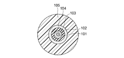
- FIG. 2 is a sectional view of an optical fiber core wire as the signal line 3A.
- the optical fiber core wire as the signal line 3A has a core 101, a clad 102, a fiber element wire coating 103, a buffer material 104, and an outer jacket 105.
- the core 101 and the clad 102 are made of, for example, quartz glass or resin.
- the outer diameter of the clad 102 can be equal to or smaller than 125 micrometers normally used in communication applications, and can be, for example, 80 micrometers (with an error of ⁇ 5%).
- the outer diameter of the clad 102 By reducing the outer diameter of the clad 102, the bending strain of the optical fiber is reduced, and the fracture probability can be reduced.
- the outer diameter of the clad 102 is too small, it becomes necessary to reduce the core size, and the connection loss tends to increase.
- the fiber strand coating 103 is made of, for example, silicon acrylate. Depending on the purpose, it may be made of another resin material (polyimide, acrylate, silicon resin, fluororesin, etc.).
- the buffer material 104 is a member arranged around the fiber bare wire coating 103 in order to increase the strength against the tensile force applied in the longitudinal direction of the optical fiber.
- the cushioning material 104 is made of, for example, a plurality of fibers and is arranged on the entire circumference of the fiber strand coating 103.
- An aramid fiber etc. can be illustrated as said fiber.
- the outer jacket 105 is preferably made of, for example, nylon or fluororesin (eg, ETFE).
- the outer diameter of the outer jacket 105 is preferably 1 mm or less, and is, for example, 800 to 900 micrometers, and is appropriately set to a desired value.
- the optical fiber core wire is easily bent, which leads to an improvement in the installation property.
- the outer diameter of the outer jacket 105 is made too small (that is, the outer jacket 105 is made too thin)
- the protection from external force becomes insufficient and the transmission loss tends to increase.
- the signal line 3A is housed inside the tubular body 31A in an unrestrained state. Specifically, the space 30 is formed between the inner peripheral surface 33A of the tubular body 31A and the signal line 3A. For example, the space 30 is filled with air, and the signal lines 3A are movably arranged in the space 30 of the tubular body 31A.
- the outer cover 4A is made of an insulating material that covers the outer peripheral surface 29A of the first linear body 2A and the outer peripheral surface 32A of the tubular body 31A.
- the insulating material include polyethylene, PVC, nylon, and silicone resin.
- the outer cover 4A is formed by extrusion molding.
- the outer jacket 4A has, for example, a shape capable of integrally covering the outer peripheral surface 29A of the first linear body 2A and the outer peripheral surface 32A of the tubular body 31A that are arranged adjacent to each other in the cross-sectional direction of the composite cable 1A,
- the cross-section has an elliptical shape or an elliptical shape.
- the composite cable 1A having the above-described configuration at least one of the first linear body 2A having conductivity and the tubular body 31A arranged adjacent to the first linear body 2A is accommodated. Since it has the book signal line 3A, the transmission of electric power by the first linear body 2A and the transmission of the optical signal by the optical fiber as the signal line 3A are realized with one cable with the minimum necessary configuration. can do.
- the signal line 3A is housed inside the tubular body 31A, even if an external force is applied to the jacket 4A of the composite cable 1A, it is difficult for the external force to directly act on the signal line 3A.
- an external force is applied to the outer jacket 4A of the composite cable 1A by making the outer dimension of the tubular body 31A equal to or smaller than the outer dimension of the first linear body 2A, Since the external force is applied to the first linear body 2A and then to the tubular body 31A, it is difficult for the external force to directly act on the signal line 3A. As a result, it is possible to suppress the adverse effect on the signal transmission by the signal line 3A due to the external force applied to the signal line 3A.
- the outer dimension of the tubular body 31A is smaller than the outer dimension of the first linear body 2A. Further, from the viewpoint that local deformation such as buckling of the tubular body 31A can be suppressed when an external force is applied to the jacket 4A of the composite cable 1A, the following (1) to (5) It is also preferable to adopt the configuration of. Here, the following (1) to (5) may be appropriately combined, but (2) and (3) have either configuration. This point also applies to the other embodiments. (1) The rigidity (hardness of bending: load/deformation amount) of the tubular body 31 is lower than both the rigidity of the first linear body 2 and the rigidity of the jacket 4.
- the tubular body 31 is movable relative to the jacket 4.
- the first linear bodies 2 are arranged at both ends of the arrangement direction of the constituent elements of the composite cable 1 (the external force affects the tubular body 31 from the arrangement direction of the constituent elements of the composite cable 1). Suppress that).
- the first linear bodies 2 are arranged on both sides of the tubular body 31 in the arrangement direction of the components of the composite cable 1 (the tubular bodies 31 are arranged in the arrangement direction of the components of the composite cable 1). Suppresses local deformation).
- the signal line 3A is accommodated in the cylindrical body 31A in an unrestrained state, that is, the signal line 3A is provided between the inner peripheral surface 33A of the cylindrical body 31A and the signal line 3A. Since the movable body 30 is movably arranged, even if the cylindrical body 31A is deformed in response to the bending of the composite cable 1A due to the influence of the external force, the signal line 3A moves inside the cylindrical body 31A. It is possible to move and avoid applying external force to the signal line 3A. Since the composite cable 1A is mounted on a vehicle or the like, it is premised that the composite cable 1A has a minimum required size. In this case, both the tubular body 31A and the space 30 have the necessary minimum size.
- the external force is applied to the signal line 3A in consideration of the adhesion between the outer surface of the tubular body 31A and the inner surface of the jacket 4A. It is possible to avoid joining.
- the rigidity of the tubular body 31A is determined by the rigidity of the first linear body 2A and the outer sheath 4A. Since the rigidity can be made lower than both the rigidity, the tubular body 31A can be plastically deformed when the composite cable 1A is curved, and the bending performance of the composite cable 1A can be improved. Further, since the composite cable 1A has a flat cross section such as an elliptical shape or an oval shape, the composite cable 1A can be moved in the short axis direction (the thickness direction of the cable) as compared with a circular cable having the same material and an equal cross section. Flexibility and bendability are improved, and the installation property to the vehicle is improved.
- first linear body 2A is a single metal wire that can be plastically deformed, when the composite cable 1A is locked by the locking component, springback does not occur in the composite cable 1A, and the composite cable 1A is combined with the locking component. The force due to the spring property of the cable 1A is less likely to be applied. This makes it possible to improve the holding performance of the composite cable 1A by the locking component.
- signal transmission on the signal line 3A is less likely to be adversely affected by the first linear body 2A as a power supply line and an electromagnetic wave generated outside.
- the composite cable 1A of the first embodiment when an external force is applied to the jacket 4A of the composite cable 1A, local deformation of the tubular body 31A is suppressed, which is sufficient as a wire harness. It is possible to provide a cable having performance.
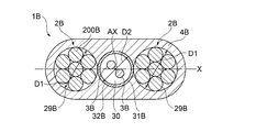
- FIG. 3 is a cross-sectional view of the composite cable according to the second embodiment.
- the composite cable 1B according to the second embodiment is implemented in that a plurality of first linear bodies 2B are provided and that the first linear body 2B is a twisted wire in which a plurality of metal wires are twisted together. Different from the composite cable 1A according to the first embodiment, the other points are the same as the composite cable 1A according to the first embodiment.
- the first linear body 2B is formed by twisting a plurality of, for example, seven metal wires 200B to function as one linear body.
- the first linear body 2B is a so-called bare stranded wire in which the outer peripheral surface 29B has no coating other than the jacket 4B.
- a plurality of, for example, two first linear bodies 2B are provided in the composite cable 1B, and a direction of an imaginary axis X provided in a cross-sectional direction that is a direction perpendicular to an axis AX indicating an extending direction (arrangement direction: It means that the same shall apply hereinafter).
- the 1st linear body 2B is arrange
- the tubular body 31B is arranged adjacent to both of the two first linear bodies 2B.
- the first linear bodies 2B are arranged at both ends of the arrangement direction of the constituent elements of the composite cable 1B.
- the tubular body 31B is a tube made of an insulating material having a circular cross section.
- the outer diameter D2 of the tubular body 31B in the cross-sectional direction is smaller than the outer diameter D1 of the first linear body 2B in the cross-sectional direction.
- the outer peripheral surface 32B of the tubular body 31B is covered with the outer cover 4B.
- Outer cover 4B is formed of the same material as outer cover 4A according to the first embodiment.
- the outer cover 4B is also formed in an oval shape in cross section corresponding to the tubular body 31B.
- Each communication line 3B is preferably movably arranged in a space 30 defined by the inner peripheral surface 28B of the tubular body 31B.
- the outer diameter of the tubular body 31B is smaller than the outer diameter of the first linear body 2B.
- the tubular bodies 31B are arranged in a row along the virtual axis X adjacent to the plurality of first linear bodies 2B. Therefore, according to the composite cable 1B of the second embodiment, even if lateral pressure is applied to the composite cable 1B, the external force acts first on the first linear body 2B and the external force acts on the tubular body 31B. Can be suppressed. Therefore, according to the composite cable 1B according to the second embodiment, when an external force is applied to the jacket 4B of the composite cable 1A, the local deformation of the tubular body 31B is suppressed, and the signal failure occurs. Can be suppressed.
- the composite cable 1B of the second embodiment since the plurality of first linear bodies 2B are adopted, the cross-sectional area equal to the total cross-sectional area of the plurality of first linear bodies 2B is obtained. Since the surface area can be made larger than that of the one first linear body 2A that it has, heat dissipation can be improved. Further, according to the composite cable 1B of the second embodiment, by providing the tubular body 31B having an insulating property so as to be sandwiched between the plurality of first linear bodies 2B, the two-system power supply system is arranged. can do.
- the first linear body 2B is, for example, a bare stranded wire made of the same material as that of the first linear body 2A. And the first linear body 2B have good adhesion, and no deviation occurs in the composite cable 1B.
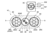
- FIG. 4 is a sectional view of a composite cable 1C according to the third embodiment.
- the composite cable 1C according to the third embodiment is different from the composite cable 1B according to the second embodiment in that the configuration of the first linear body 2C, the configuration of the tubular body 31C, and the type of the signal line 3C are different.
- the other points are similar to those of the composite cable 1B according to the second embodiment.
- the tubular body 31C in the composite cable 1C is, for example, a metal wire (copper electric wire) used in the first linear body 2A of the composite cable 1A according to the first embodiment. It is a cylindrical material made of a conductive material, that is, a non-insulating material.
- the tubular body 31C is formed by, for example, extrusion molding.
- the first linear body 2C in the composite cable 1C is formed by twisting a plurality of, for example, seven metal wires 200C into one linear body, and the outer periphery thereof.
- the surface 29C is covered with an insulating coating 5 made of an insulating material. Therefore, in the first linear body 2C, the outer peripheral surface of the insulating coating 5 is covered with the outer cover 4C.
- the insulating coating 5 is made of, for example, the same insulating material as the outer cover 4D (outer cover 4A).
- the insulating coating 5 is formed by extrusion molding, for example.
- the signal line 3C is, for example, a metal wire (metal wire).
- the signal line 3C includes, for example, a twisted wire 301 and a jacket 302 that covers the outer circumference of the twisted wire 301.
- the twisted wire 301 is formed by twisting a plurality of covered electric wires 311.
- FIG. 4 illustrates an example in which two covered electric wires 311 are twisted together, but the number of the covered electric wires 311 is not particularly limited.
- Each covered electric wire 311 includes a conductor 3110 made of, for example, a metal, and an insulating layer 3111 made of an insulating material that covers the outer periphery of the conductor 3110.
- the conductor 3110 can be formed of, for example, the same material as that of the first linear body 2A.
- the insulating layer 3111 can be formed of, for example, the same material as the outer cover 4A.
- the jacket 302 can be formed of, for example, the same material as the outer cover 4A.
- the conductor 3110 may be a single wire or a stranded wire.
- the tubular body 31C is made of a non-insulating material. Therefore, according to the composite cable 1C according to the third embodiment, in addition to the effect of the composite cable 1B according to the second embodiment, the electromagnetic waves generated from the first linear body 2C or other devices are tubular. It is possible to suppress the occurrence of signal failure without interfering with the second linear body 3C that is the signal line formed by the metal wire inside the body 31C. Note that the rigidity of the tubular body 31C is the same as in the above-described respective embodiments from the viewpoint of suppressing local deformation of the tubular body 31C when an external force is applied to the jacket 4C of the composite cable 1C.
- the rigidity may be lower than the rigidity of the first linear body 2C or the rigidity of the outer cover 4C. Further, the outer diameter of the tubular body 31C is smaller than the inner diameter of the insulating coating 5 of the first linear body 2C, and the rigidity of the tubular body 31C is lower than the rigidity of the insulating coating 5 of the first linear body 2C. And so on.
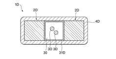
- FIG. 5 is a perspective view of the composite cable 1D according to the fourth embodiment.
- the composite cable 1D according to the fourth embodiment is different from the composite cable 1B according to the second embodiment in that the configuration of the first linear body 2D and the shape of the tubular body 31D are different, and in other respects. The same as the composite cable 1B according to the second embodiment.
- the first linear body 2D is a solid single wire made of a metal material like the first linear body 2A in the composite cable 1A according to the first embodiment. (Metal wire). Unlike the first linear body 2A, the first linear body 2D has a rectangular cross section.
- the first linear body 2D may be any metallic material having conductivity, and examples thereof include metallic materials such as aluminum, copper, copper alloys, tin-plated wires, iron, and nickel.
- the tubular body 31D is made of a material having an insulating property, and is arranged adjacent to the first linear body 2D in the cross-sectional direction similarly to the tubular body 31A. Unlike the tubular body 31A, the tubular body 31D has a rectangular cross section.
- both the first linear body 2D and the tubular body 3D are rectangular, so that they are When they are collectively covered with the outer cover 4D, they are easily aligned. That is, according to the composite cable 1D according to the fourth embodiment, it is possible to facilitate the work during manufacturing.
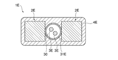
- FIG. 6 is a sectional view of a composite cable 1E according to the fifth embodiment.
- the composite cable 1E according to the fifth embodiment differs from the composite cable 1D according to the fourth embodiment in that the shape of the tubular body 31E is different, and in other respects, the composite cable 1D according to the fourth embodiment. Is the same as.
- the tubular body 31E is different from the tubular body 31D of the composite cable 1D according to the fourth embodiment, and the tubular body 31A of the composite cable 1A according to the first embodiment.
- the cross-section has a circular shape.
- FIG. 7 is a diagram showing the configuration of the composite cable 1F according to the sixth embodiment.
- the composite cable 1F according to the sixth embodiment differs from the composite cable 1B according to the second embodiment in that the shape of the tubular body 31F is different, and in other respects, the composite cable 1B according to the second embodiment. Is the same as.
- the tubular body 31F is different from the tubular body 31B of the composite cable 1B according to the second embodiment, and the tubular body 31D of the composite cable 1D according to the fourth embodiment.
- the cross-section has a rectangular shape.
- FIG. 8 is a diagram showing a configuration of a composite cable 1G according to the seventh embodiment.
- the composite cable 1G according to the seventh embodiment differs from the composite cable 1B according to the second embodiment in that the shape of the first linear body 2G is different, and in other respects, the composite cable 1G according to the second embodiment is different. It is similar to the cable 1B.
- the first linear body 2G has a triangular shape in cross section unlike the first linear body 2B of the composite cable 1B according to the second embodiment.
- the cross-sectional shape of the first linear body 2G is not limited to the example shown in FIG. 8, and various angular shapes such as a hexagonal shape can be adopted.
- FIG. 9 is a sectional view of the composite cable according to the eighth embodiment.
- the shape of the first linear body 2H is rectangular in cross section, and the structure of the first linear body 2H is a flat stranded wire.
- the number of the first linear bodies 2H is increased from two to six, which is different from the composite cable 1D according to the fourth embodiment, and in other respects, the composite cable according to the fourth embodiment. It is similar to the cable 1D.
- the first linear bodies 2H are equivalent to the first linear bodies 2D while increasing the number of the first linear bodies 2D from 2 to 6 in the composite cable 1D.
- the flat stranded wire has a rectangular shape (for example, a rectangular shape) in cross section in order to be arranged in the space having the cross-sectional area.
- the structure of the flat stranded wire in the first linear body 2D is obtained by twisting a plurality of metal wires 200H together like the first linear body 2B in the composite cable 1B according to the second embodiment.
- the first linear bodies 2H are arranged such that the short sides thereof face the longitudinal direction in cross-section, so that three first linear bodies 2H are arranged on each side of the tubular body 31H.
- the first linear body 2H may be a plate-shaped conductor having a rectangular cross section, a plate-shaped coated conductor covered with the conductor, or a flat coated stranded wire coated with the first linear body 2H, and a tubular body. Since the rigidity of 31H is lower than both the rigidity of the first linear body 2H and the rigidity of the jacket 4H, local deformation of the tubular body 31H due to bending of the composite cable 1H can be suppressed.
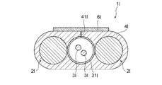
- FIG. 10 is a perspective view of a composite cable 1I according to the tenth embodiment.
- the composite cable 1I according to the tenth embodiment is different from the composite cable 1B according to the second embodiment in that it has a configuration of the first linear body 2I, a slit portion 41I, and a closing member 6I, and in other respects. Is similar to the composite cable 1B according to the second embodiment.
- the first linear body 2I is a solid single wire made of a metal material, similar to the first linear body 2A in the composite cable 1A according to the first embodiment. (Metal wire).
- the first linear body 2I shown in FIG. 10 is not limited to a solid single wire (metal wire), and may be a twisted wire.
- the first linear body 2I is provided in plural in the composite cable 1I, for example, two and is arranged along the direction of an imaginary axis X provided in a cross-sectional direction that is a direction perpendicular to the axis AX indicating the extending direction. Has been done.
- the first linear body 2I is arranged so as to sandwich the tubular body 31I in a cross-sectional direction that is a direction perpendicular to the extending direction of the composite cable 1I.
- the tubular body 31I is arranged adjacent to both of the two first linear bodies 2I.
- the slit portion 41I is provided, for example, between the outer surface of the outer cover 4I and the inner surface of the tubular body 31I.
- the slit portion 41I can separate the outer cover 4I and the tubular body 31I at one location in the cross-sectional direction of the composite cable 1I to connect the outside of the composite cable 1I and the space on the inner side surface of the tubular body 31I. .. Therefore, in the composite cable 1I, the second linear body 3I can be inserted into the space inside the tubular body 31I by using the slit portion 41I.
- the slit portion 41I divides the outer cover 4I and the tubular body 31I in the cross-sectional direction at the time of manufacturing the composite cable 1I described later (that is, before inserting the second linear body 3I) to the outside of the composite cable 1I.
- the space on the inner side surface of the tubular body 31I are not in communication with each other, that is, a cut, a V-shaped groove, or a thin portion provided in a part between the outer side of the composite cable 1I and the tubular body 31I.
- the tubular body 31I By inserting the second linear body 3I, by applying an external force to the side where the slit portion 41I of the composite cable 1I opens (including passing a tool or the like through the slit portion 41I), the tubular body 31I. Can be subsequently separated at the position of the slit portion 41I in the cross-sectional direction of the composite cable 1I so that the outside of the composite cable 1I and the space on the inner side surface of the tubular body 31I communicate with each other.
- the closing member 6I is provided on the outer surface of the outer cover 4I where the slit portion 41I is provided.
- the closing member 6I closes the slit portion 41I opened to the outside and the cylindrical body 31I provided inside the slit portion 41I to the outside.
- the closing member 6I is formed, for example, by welding a resin tape attached to the outer cover 4I or a part of the outer cover 4I by laser heating, roller heating, or the like.
- the closing member 6I is not limited to the specific example described above as long as it can be sealed to close the slit portion 41I.
- the slit portion 41I in addition to the function and effect of the composite cable 1B according to the second embodiment, since the slit portion 41I is provided, the tubular shape provided inside the slit portion 41I at the time of manufacturing.
- the second linear body 3I such as a signal line can be easily inserted into the body 31I.
- the closing member 6I for closing the slit portion 41I since the closing member 6I for closing the slit portion 41I is provided, the slit portion 41I after the insertion of the second linear body 3I is surely closed and the second wire is provided inside the tubular body 31I.
- the shape body 3I can be held. That is, according to the composite cable 1I according to the ninth embodiment, the work at the time of manufacturing can be facilitated.
- the rigidity of the tubular body 31I is set in the same manner as in each of the above-described embodiments.
- the rigidity of the first linear body 2I and the rigidity of the outer cover 4I can be made lower.
- FIG. 11 is a sectional view of a composite cable 1J according to the tenth embodiment.
- the composite cable 1J according to the tenth embodiment differs from the composite cable 1I according to the ninth embodiment in that the shape of the slit portion 41J is different, and in other respects, it is different from the composite cable 1I according to the ninth embodiment. The same is true.
- the slit portion 41J differs from the slit portion 41I of the composite cable 1I according to Embodiment 9 in that the outer jacket 4J and the tubular body 31J have an angle in the cross-sectional direction. And is obliquely divided so that the outside of the composite cable 1J communicates with the space on the inner side surface of the tubular body 31J.
- the position where the slit portion 41J is provided is not limited to this.
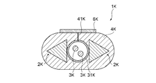
- FIG. 12 is a diagram showing the structure of the composite cable 1K according to the eleventh embodiment.
- the composite cable 1K according to the eleventh embodiment differs from the composite cable 1I according to the ninth embodiment in that the shape of the first linear body 2K is different, and in other respects, the composite cable according to the ninth embodiment is different. It is similar to the cable 1I.
- the first linear body 2K is different from the first linear body 2I of the composite cable 1I according to the ninth embodiment, and is different from that of the composite cable 1G according to the seventh embodiment. It has a triangular shape in cross section, like the first linear body 2G.
- the cross-sectional shape of the first linear body 2I is not limited to the example shown in FIG. 12, and various angular shapes such as a hexagonal shape can be adopted.
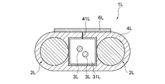
- FIG. 13 is a diagram showing the configuration of the composite cable 1L according to the twelfth embodiment.
- the composite cable 1L according to the twelfth embodiment differs from the composite cable 1I according to the ninth embodiment in that the shape of the tubular body 31L is different, and in other respects, the composite cable 1I according to the ninth embodiment is different. Is the same as.
- the tubular body 31L is different from the tubular body 31I of the composite cable 1I according to the ninth embodiment, and the tubular body 31D of the composite cable 1D according to the fourth embodiment.
- the cross-section has a rectangular shape.
- FIG. 14 is a diagram showing the configuration of the composite cable 1M according to the thirteenth embodiment.
- the composite cable 1M according to the thirteenth embodiment differs from the composite cable 1I according to the ninth embodiment in that the shape of the first linear body 2M is different, and in other respects, the composite cable according to the ninth embodiment is different. It is similar to the cable 1I.
- the first linear body 2M is different from the first linear body 2I of the composite cable 1I according to the ninth embodiment, and is different from that of the composite cable 1D according to the fourth embodiment.
- the cross-section is rectangular like the first linear body 2D.
- FIG. 15 is a diagram showing the configuration of the composite cable 1N according to the fourteenth embodiment.
- the composite cable 1N according to the fourteenth embodiment differs from the composite cable 1M according to the thirteenth embodiment in that the shape of the tubular body 31N is different, and in other respects, the composite cable 1N according to the fourteenth embodiment. Is the same as.
- the tubular body 31N is different from the tubular body 31M of the composite cable 1M according to the thirteenth embodiment, and the tubular body 31D of the composite cable 1D according to the fourth embodiment.
- the cross-section has a rectangular shape.
- FIG. 16 is a sectional view of the composite cable 10 according to the fifteenth embodiment.
- the composite cable 1O according to the fifteenth embodiment differs from the composite cable 1I according to the ninth embodiment in that the shape of the jacket 4O is different, and in other respects, it is different from the composite cable 1I according to the ninth embodiment. The same is true.
- the outer jacket 4O is different from the outer jacket 4O of the composite cable 1I according to the ninth embodiment in that the two first linear bodies 20 are covered with two jackets.
- the shape is such that an elliptical shape is arranged in the cross-sectional direction.
- the slit portion 41O is formed at a position where the two elliptical shapes of the jacket 4O are joined in the cross-sectional direction. Therefore, in the composite cable 1O, the slit portion 41O can be easily formed by providing the slit portion 41O in the thin portion of the jacket 4O.
- FIG. 17 is a sectional view of a composite cable 1P according to the sixteenth embodiment.
- the composite cable 1P according to the sixteenth embodiment differs from the composite cable 1O according to the fifteenth embodiment in that the shape of the closing member 6P is different, and in other respects, the composite cable 1O according to the fifteenth embodiment. The same is true.
- the closing member 6P is formed in a shape in which two elliptical shapes are arranged in the cross-sectional direction. It is provided at two places so as to linearly connect the vertices of the outer cover 4P. Further, in the composite cable 1P, in a region between the inner side of the closing member 6P and the outer jacket 4P, there are two spaces (linear body arranging portions 7P) in which the second linear bodies 3P can be arranged. Has been formed.
- the composite cable 1P of the sixteenth embodiment the same operational effect as that of the composite cable 1I of the above-described ninth embodiment can be obtained, and the composite cable 1P is formed by the outer cover 4P and the closing member 6P.
- the linear body arranging portion 7P that is formed, more second linear bodies 3P can be arranged.
- the second linear body 3P can be arranged separately in the cylindrical body 31P and the linear body arranging portion 7P, the second linear body 3P can be appropriately arranged according to the wiring form of the composite cable 1P. Can be placed.
- FIG. 18 is a sectional view of a composite cable 1Q according to the seventeenth embodiment.
- the composite cable 1Q according to the seventeenth embodiment differs from the composite cable 1P according to the sixteenth embodiment in that the composite cable 1Q does not have the closing member 6O, but has the covering member 10Q that covers the outside of the jacket 4O. This point is the same as the composite cable 1P according to the sixteenth embodiment.
- the covering member 10Q is different from the closing member 6P of the composite cable 1P according to the sixteenth embodiment in that it is formed in a shape in which two elliptical shapes are arranged in the cross-sectional direction.
- the outer cover 4Q is provided so as to cover the entire outer cover 4Q from the outside.
- the covering member 10Q has an elliptical shape in cross section in FIG. 18, but may have an elliptical shape in cross section.
- a space (the linear body arranging portion 7Q) in which the second linear body 3Q can be arranged is formed in a region between the inside of the covering member 10Q and the jacket 4Q. There is.
- FIG. 19 is a sectional view of a composite cable 1R according to the eighteenth embodiment.
- the number of first linear bodies 2R, the number of second linear bodies 3R, the number of tubular bodies 31R, the number of slit portions 41R, and the number of closing members 6R are the same.
- the different points are different from the composite cable 1I according to the ninth embodiment, and the other points are the same as the composite cable 1I according to the ninth embodiment.
- the composite cable 1R is provided with three first linear members 2R, two tubular members 31R, and four second linear members 3R.
- the tubular bodies 31R are arranged alternately with the first linear bodies 2R.
- the first linear bodies 2R are arranged at both ends of the arrangement of the constituent elements of the composite cable 1R in the arrangement direction.
- the slit portion 41R and the closing member 6R in the cross-sectional direction of the composite cable 1R are provided corresponding to each of the two tubular bodies 31R.
- the number of first linear bodies 2R, the number of second linear bodies 3R, the number of tubular bodies 31R, the number of slit portions 41R, and the number of closing members 6R are not limited. ..
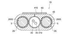
- FIG. 20 is a diagram showing the structure of the composite cable 1S according to the nineteenth embodiment.
- the composite cable 1S according to the nineteenth embodiment differs from the composite cable 1I according to the ninth embodiment in that the configuration of the first linear body 2S is different, and in other respects, the composite cable according to the ninth embodiment is different. It is similar to the cable 1I.
- the first linear body 2S is different from the first linear body 2I of the composite cable 1I according to the ninth embodiment in the outer periphery of the metal wire 200S made of a single metal wire.
- the surface is covered with an insulating coating 5 made of an insulating material. Therefore, in the first linear body 2S, the outer peripheral surface of the insulating coating 5 is covered with the outer cover 4S.
- FIG. 21 is a diagram showing the structure of the composite cable 1T according to the twentieth embodiment.
- the composite cable 1T according to the twentieth embodiment is different from the composite cable 1I according to the ninth embodiment in that the configuration of the first linear body 2T is different, and in other respects, the composite cable 1T according to the ninth embodiment is different. It is similar to the cable 1I.
- the first linear body 2T differs from the first linear body 2I of the composite cable 1I according to the ninth embodiment, and the first linear body 2T according to the second embodiment. Similar to the body 2B, a plurality of, for example, seven metal wires 200T are twisted into one linear body, and the outer peripheral surface thereof is covered with an insulating coating 5 made of an insulating material. Therefore, in the first linear body 2T, the outer peripheral surface of the insulating coating 5 is covered with the outer cover 4T.
- FIG. 22 is a sectional view of the composite cable 1B according to the twenty-first embodiment.
- FIG. 22 is a diagram showing a configuration in which an external terminal is connected to an end portion of the composite cable 1B according to the embodiment of the present invention. In the figure, as an example, a case is shown in which the external terminals 8 and 9 are connected to the composite cable 1B according to the second embodiment.
- the external terminal 8 (first external terminal) is a simple connection member for facilitating connection between the first linear body 2B in the composite cable 1B and an external device or other wiring.
- the external terminal 8 a crimp terminal or the like can be exemplified.
- the external terminal 8 is connected to the end of the first linear body 2B in the extending direction.
- the external terminal 9 (second external terminal) is a simple connection member for facilitating the connection between the signal line 3B in the composite cable 1B and an external device or another wiring.
- the signal line 3B is an optical fiber
- various optical connectors such as FC, SC, LC can be exemplified as the external terminal 9.
- the external terminals 9 are respectively connected to the ends of the signal lines 3B in the extending direction.
- the case where the external terminals 8 and 9 are connected to the composite cable 1B according to the second embodiment has been illustrated, but the composite cables 1A, 1C to 1T according to the first to third embodiments are provided. Similarly, the external terminals 8 and 9 can be connected.
- FIG. 23 is a flowchart showing the flow of the method for manufacturing the composite cable according to the embodiment of the present invention.
- the flow of the method for manufacturing the composite cable 1A according to the first embodiment will be described as a representative, but the composite cables 1B to 1T according to the other embodiments can be manufactured according to a substantially similar flow. ..
- the first linear body 2A having conductivity is formed (step S101).
- the first linear body 2A is formed by extruding a metal material such as aluminum, copper, a copper alloy, a tin-plated wire, iron, and nickel.
- a metal material such as aluminum, copper, a copper alloy, a tin-plated wire, iron, and nickel.
- an impurity or an additive which is a relatively flexible material from the viewpoint of ensuring bendability of the composite cable.
- a copper-based or aluminum-based material having a small amount of is preferable is the same as in each of the above-described embodiments.
- the cylindrical body 31A having an insulating property is formed (step S102).
- the tubular body 31A is formed by extrusion-molding an insulating material such as polyethylene, PVC, nylon, or silicone resin.
- a jacket 4A made of an insulating material that covers the outer peripheral surface 29A of the first linear body 2A and the outer peripheral surface 32A of the tubular body 31A formed in steps S101 and S102 is formed (step S103).
- the outer peripheral surface 29A of the first linear body 2A and the outer peripheral surface 29A of the tubular body 31A are extrusion-molded (for example, batch extrusion molding) with a material such as polyethylene, PVC, nylon, or a silicone resin.
- a material such as polyethylene, PVC, nylon, or a silicone resin.
- the slit portions 41I are formed after the jackets 4I to 4T are formed by extrusion molding.
- the jackets 4I to 4T are cut open, or a processing for forming a cut or a V-shaped groove is performed.
- the second linear body 3A is inserted into the cylindrical body 31A having the outer cover 4A formed in step S103 (step S104).
- the subassembly having the outer cover 4A formed on the tubular body 31A is cut so that the subassembly has a predetermined length, and the end of the cut subassembly (the end of the tubular body 31A) is cut.
- An optical fiber as the signal line 3A is inserted.
- the composite cables 1I to 1T in which the jackets 4I to 4T and the tubular bodies 31I to 31T are provided with the slit portions 41I to 41T, the slit portions 41I to 41T are opened to open the second linear bodies 3I to 3T.
- the closing members 6I to 6T are provided by an appropriate method such as.
- step S105 the simple connection member 8 as the first external terminal is connected to the end portion in the extending direction of the first linear body 2A on which the jacket 4A is formed in step S103 (step S105). ..
- the simple connection member 9 as the second external terminal is connected to the end portion in the extending direction of the second linear body 3A inserted into the cylindrical body 31A in step S104 (step). S106).
- the connection of the simple connection members 8 and 9 in steps S105 and S106 can be realized by using a known method such as a conventional crimp terminal connection method.
- the composite cable 1A according to the first embodiment can be manufactured.
- step S104 the case where the signal line (optical fiber) is inserted as the second linear body 3A inside the cylindrical body 31A in which the jacket 4A is formed in step S103 is illustrated.
- a metal wire may be used, and a thread member that does not function as a transmission line (for example, a drawstring) may be inserted instead of the signal line.
- step S104 the drawstring as the linear body 3A is inserted into the tubular body 31A in a movable state. Then, the one in which the drawstring is inserted inside the tubular body 31A in which the jacket 4A is formed may be shipped as a composite cable.
- the signal line is introduced into the tubular body 31A by pulling the draw string with the signal line such as the metal wire or the optical fiber tied to the draw string.
- the signal line such as the metal wire or the optical fiber tied to the draw string.
- an arbitrary signal line such as a metal wire or an optical fiber can be introduced into the composite cable at the site where the composite cable is installed.
- the slit portions 41I to 41T provided on the outer jackets 4I to 4T and the tubular bodies 31I to 31T are formed, and after formation. Open the slit portions 41I to 41T, insert the second linear bodies 3I to 3T into the tubular bodies 31I to 31T, and close the slit portions 41I to 41T using the closing members 6I to 6T. It can be done in one line.
- FIG. 24 and 25 are diagrams showing an example of wiring when the composite cable according to the embodiment of the present invention is used as a vehicle-mounted wire harness.
- FIG. 24 is a plan view of a wiring harness wiring structure using any of the composite cables 1A to 1T according to the above-described embodiment
- FIG. 25 is a schematic diagram showing the wiring harness wiring structure. A partial perspective view is shown.
- Vehicle 600 may be, for example, a vehicle including a hybrid vehicle, an electric vehicle, a fuel cell vehicle, or the like.
- the wire harness wiring structure 500 includes a first power supply trunk line 12a connected to the power supply 10 mounted on the vehicle 600 and a first power supply trunk line as a power supply system.
- a first power distributor 11a connected to 12a
- a second power trunk line 12b connected to the first power distributor 11a and routed in the front-rear direction of the vehicle, and a second power trunk line 12b.
- the wiring harness wiring structure 500 serves as a communication infrastructure and is connected to the first communication control unit 21a and the first communication control unit 21a, and is also a first communication trunk line arranged in the front-rear direction of the vehicle.
- branch lines (communication branch lines and power branch lines) 13 connected to the respective power supply distributors of the first to fourth power supply distributors 11 a to 11 d, and the first power supply distributor 11 connected to the respective branch lines 13.
- Auxiliary equipment 14 branch lines (communication branch line and power supply branch line) 15 connected to each communication control unit of the first to fourth communication control units 21a to 21d, and each branch line 15 And a second auxiliary machine 16.
- the first power supply distributor 11a and the first communication control unit 21a are housed and integrated in the first housing 31.
- the second power distributor 11b and the first communication controller 21b are housed in the second housing 32
- the third power distributor 11c and the third communication controller 21c are housed in the third housing 33.
- the fourth power distributor 11d and the fourth communication control unit 21d are housed in the fourth housing 34 and are integrated.
- the trunk line including the power supply line and the communication line that is, at least a part of the power supply trunk lines 12a to 12d and the communication trunk lines 22a to 22c, the composite according to any one of the above-described first to eighth embodiments.
- the cables 1A to 1T can be adopted.
- at least a part of the branch lines (power supply branch line and communication branch line) 13 and 15 branched from the main line is combined with the composite according to any one of the above-described first to twenty-first embodiments.
- the cables 1A to 1T can be adopted.
- the composite cables 1A to 1T As described above, by adopting the composite cables 1A to 1T according to any of the above-described first to twentieth embodiments in the vehicle wire harness wiring structure 500, the power cable and the communication line are connected by one cable. Since it can be routed, it is possible to further improve the wireability of the wire harness in the vehicle. Further, in the wiring harness wiring structure 500 of FIG. 25, the composite cables 1A to 1T have a bent portion BP along the form of the vehicle 600 to be wired. The bending portion BP may have a small bending radius. In the conventional composite cable, where the influence of bending on the communication line is concerned, the external force is applied to the composite cable by applying the composite cables 1A to 1T according to any of Embodiments 1 to 20 in the present invention. It is possible to suppress local deformation of the tubular bodies 31A to 31T due to, and to avoid applying external force to the second linear bodies 3A to 3T.
- the power supply trunk lines 12a to 12d and the branch lines 13 and 15 are a signal line to which a power supply voltage is supplied and a signal line (ground line) to which a ground voltage is supplied.
- the power supply trunk lines 12a to 12d and the branch lines 13 and 15 are signal lines to which a power supply voltage is supplied, and a ground line to which a ground voltage is supplied separately from these power supply lines. May be provided.
- the second linear bodies 3A and 3C are communication lines such as optical fibers and metal wires
- the second linear bodies 3A and 3C are It may be a thread member (such as a drawstring) that does not function as a line.
- FIG. 26 is a cross-sectional view showing another aspect of the composite cable 1A1 according to the first embodiment.
- FIG. 27 is a sectional view showing still another aspect of the composite cable 1A2 according to the first embodiment.
- the composite cables 1A1 and 1A2 may have a slit portion 41A and a closing member 6A.
- the slit portion 41A and the closing member 6A may be provided on the side surface in the lateral direction in the cross section of the jacket 4A of the composite cable 1A1 as shown in FIG. 26, or as shown in FIG. 27. It may be provided on the upper surface which corresponds to the longitudinal direction in the cross section of the jacket 4A of 1A2.
- the first linear bodies 2B are arranged one by one so as to sandwich the tubular body 31B at both ends of the arrangement direction of the constituent elements of the composite cable 1B, but this is not the only option.
- the two first linear bodies 2B1 may be arranged so as to sandwich the tubular body 31B1, or three or more first linear bodies 2B1 may be arranged. In this way, when an external force is applied to the jacket 4B1 of the composite cable 1B1, local deformation of the tubular body 31B1 is further suppressed.
- the first linear body 2E of the composite cable 1E has a rectangular shape (square shape) in cross section, but the present invention is not limited to this.
- the shape body 2E1 may be rectangular in cross section and may be flat in the arrangement direction of the components of the composite cable 1E1. In this way, the composite cable 1E1 is easily bent in the flat direction, and heat dissipation is also improved.
- the dimension of the tubular body 31E1 in the thickness direction of the composite cable 1E1 is smaller than the dimension of the first linear body 2E1 in the thickness direction of the composite cable 1E1, local deformation of the tubular body 31E1 is further suppressed. To be done.
- the first linear body 2E1 and the tubular body 31E1 are arranged side by side with the outer jacket 4E1 in between, but the first linear body 2E1 and the tubular body 31E1 may be adjacent to each other.
- the first linear body 2A of the composite cable 1A has a circular cross-sectional shape, but the present invention is not limited to this.
- the cross-section may be rectangular and may be flat in the arrangement direction of the components of the composite cable 1A3.
- the composite cable 1A3 is easily bent in the flat direction, and heat dissipation is also improved.
- the dimension of the tubular body 31A3 in the thickness direction of the composite cable 1A3 is smaller than the dimension of the first linear body 2A3 in the thickness direction of the composite cable 1A3, local deformation of the tubular body 31A3 is further suppressed. To be done.
- the first linear body 2A3 and the tubular body 31A3 are arranged side by side with the outer jacket 4A3 in FIG. 30, the first linear body 2A3 and the tubular body 31A3 may be adjacent to each other.
- the composite cables 1A3, 1C1, 1F1 according to the other aspects of the first, second, and fifth embodiments formed as described above, the composite cables 1A, 1C according to the first, second, and fifth embodiments described above.
- the same effect as 1F can be obtained. Further, it can be similarly applied to other embodiments.
- Composite cable 2A to 2H, 2A1 to 2A3, 2B1, 2E1... First linear body, 3A to 3B, 3D to 3T, 3A1 to 3A3, 3B1, 3E1... 2 linear body, signal line (optical fiber), 3C... linear body, signal line (metal line), 4A to 4T, 4A1 to 4A3, 4B1, 4E1... Outer sheath, 5... Insulation coating, 6A, 6I to 6T ... Closing member, 7... Linear body arranging portion, 8... First external terminal (simple connection member), 9... Second external terminal (simple connection member), 12a to 12d... Power supply trunk line, 13, 15...
Landscapes
- Engineering & Computer Science (AREA)
- Manufacturing & Machinery (AREA)
- Physics & Mathematics (AREA)
- Architecture (AREA)
- Civil Engineering (AREA)
- Structural Engineering (AREA)
- General Physics & Mathematics (AREA)
- Optics & Photonics (AREA)
- Insulated Conductors (AREA)
- Communication Cables (AREA)
Abstract
ワイヤハーネスとして十分な性能を有する複合ケーブルを提供する。 本発明の代表的な実施の形態に係る複合ケーブル(1A)は、導体を含む第1線状体(2A)と、第1線状体(2A)の延在方向に延びる筒状体(31A)と、筒状体(31A)の内部に非拘束状態で収容された第2線状体(3A)と、第1線状体(2A)および筒状体(31A)の外周面を被覆する絶縁材料から構成された外被(4A)と、を有し、第1線状体(2A)と筒状体(31A)は、配列方向に並んで配置され、かつ第1線状体(2A)および外被(4A)が、外力による筒状体(31A)の局所的な変形を抑制可能に構成されている。
Description
本発明は、複合ケーブル、ワイヤハーネスの配索構造、及び複合ケーブルの製造方法に関し、例えば、車載用の複合ケーブル、ワイヤハーネスの配索構造、及び複合ケーブルの製造方法に関する。
自動車等の配線システムには、互いに独立して製造された通信ケーブルと電源ケーブルを必要に応じてテープなどで集束した構造のワイヤハーネスが使用されている。
近年、電気信号の伝送と光信号の伝送とが可能な複合ケーブルを採用した車載用のワイヤハーネスが増えつつある。例えば、特許文献1には、光ファイバとその被覆の間に、めっきなどで導電性材料の層を表面に形成した抗張力繊維群が充填された、車載用の複合ケーブルが開示されている。また、特許文献2には、電源線と通信線とが複合された屋内用の複合ケーブルが開示されている。
近年、電気信号の伝送と光信号の伝送とが可能な複合ケーブルを採用した車載用のワイヤハーネスが増えつつある。例えば、特許文献1には、光ファイバとその被覆の間に、めっきなどで導電性材料の層を表面に形成した抗張力繊維群が充填された、車載用の複合ケーブルが開示されている。また、特許文献2には、電源線と通信線とが複合された屋内用の複合ケーブルが開示されている。
しかしながら、従来の複合ケーブルは、車載用のワイヤハーネスとして十分な性能を有しているとは言い難かった。
例えば、特許文献1に開示された複合ケーブルを構成する導電性抗張力繊維は、アラミド等の抗張力繊維表面に銅等導電性金属をめっき等で形成されている。そのため、車載用ワイヤハーネスとして要求される十分な導電性能(電気抵抗)を確保するには、従来の絶縁電線と同等の導電体断面積が必要となり、その屈曲性能も従来の絶縁電線と同等となると考えられる。すなわち、特許文献1に記載の技術では、車載用ワイヤハーネスとして要求される導電性能を満足するために、複合ケーブルの径が従来の絶縁電線を用いる場合よりも大きくなる。その結果、複合ケーブルの屈曲性能が低下するとともに、複合ケーブルの重量が増すおそれがある。
また、特許文献2に開示された複合ケーブルは、中空チューブが複合ケーブルの断面の端にあり、中空チューブのみが外力の影響を受けることがある。また、中空チューブが外力の影響によって局所的に変形して光コードを圧迫し、光コードの伝送損失の増大、または光コードの破断などが発生するおそれがある。特に、複合ケーブルをワイヤハーネスとして用いる場合、車体に沿って配線しようとすると、曲げ半径の小さい曲げ箇所が増えて、上述の中空チューブの局所的な変形(座屈等)が起こりやすくなる。このため、屈曲性能が高いとは言い難い。
このように、従来の複合ケーブルは、ワイヤハーネスとして十分な性能を有しているとは言い難かった。
このように、従来の複合ケーブルは、ワイヤハーネスとして十分な性能を有しているとは言い難かった。
本発明は、上述した課題に鑑みてなされたものであり、ワイヤハーネスとして十分な性能を有する複合ケーブルを提供することを目的とする。
本発明の代表的な実施の形態に係る複合ケーブルは、導電材料により形成されている導体を含む少なくとも1本の第1線状体と、前記第1線状体の延在方向に延びる筒状体と、前記筒状体の内部に非拘束状態で収容された少なくとも1本の第2線状体と、前記第1線状体及び前記筒状体の外周面を被覆する絶縁材料から構成された外被と、を有し、前記第1線状体と前記筒状体は、前記第1線状体の延在方向に垂直な断面の一方向である配列方向に並んで配置されており、前記第1線状体および前記外被は、外力の影響による前記筒状体の局所的な変形を抑制可能に構成されていることを特徴とする。
本発明に係る複合ケーブルによれば、ワイヤハーネスとして十分な性能を有する複合ケーブルを提供することが可能となる。
1.実施の形態の概要
先ず、本願において開示される発明の代表的な実施の形態について概要を説明する。なお、以下の説明では、一例として、発明の構成要素に対応する図面上の参照符号を、括弧を付して記載している。
先ず、本願において開示される発明の代表的な実施の形態について概要を説明する。なお、以下の説明では、一例として、発明の構成要素に対応する図面上の参照符号を、括弧を付して記載している。
〔1〕本発明の代表的な実施の形態に係る複合ケーブル(1A~1T)は、導電材料により形成されている導体を含む少なくとも1本の第1線状体(2A~2T)と、前記第1線状体の延在方向に延びる筒状体(31A~31T)と、前記筒状体の内部に非拘束状態で収容された少なくとも1本の第2線状体(3A~3T)と、前記第1線状体及び前記筒状体の外周面を被覆する絶縁材料から構成された外被(4A~4T)と、を有し、前記第1線状体と前記筒状体は、前記第1線状体の延在方向に垂直な断面の一方向である配列方向に並んで配置されており、前記第1線状体および前記外被は、外力の影響による前記筒状体の局所的な変形を抑制可能に構成されていることを特徴とする。
また、上記〔1〕に記載の複合ケーブルにおいて、前記第1線状体は、複数が備えられ、前記筒状体は、前記配列方向に沿って複数の前記第1線状体と隣接して配置されていてもよい。
また、上記〔1〕に記載の複合ケーブルにおいて、前記筒状体の内周面と前記線状体との間には空間(30)が形成されていてもよい。
また、上記〔1〕に記載の複合ケーブル(1C)において、前記筒状体は、導電体(31C)であってもよい。
また、上記〔1〕に記載の複合ケーブル(1A,1B,1D~1T)において、前記筒状体は、絶縁体(31A,31B,31D~31T)であってもよい。
また、上記〔1〕に記載の複合ケーブル(1A,1D~1G,1I~1R)において、前記第1線状体は、1本の金属線により構成されている単線(2A,2D~2G,2I~2R)であってもよい。
また、上記〔1〕に記載の複合ケーブル(1B,1C,1H,1T)において、前記第1線状体は、複数の金属線を撚り合わせた撚線(2B,2C,2H,2T)であってもよい。
また、上記〔1〕に記載の複合ケーブル(1C)において、前記外被の内周面に接し前記第1線状体の外周面を被覆する絶縁材料から構成された絶縁被覆(25C)を有していてもよい。
また、上記〔1〕に記載の複合ケーブル(1A~1C,1E,1G,1I~1K,1M,1O~1T)において、前記筒状体は、断面視円形状であってもよい。
また、上記〔1〕に記載の複合ケーブル(1D,1F、1H,1L~1N)において、前記筒状体は、断面視矩形状であってもよい。
また、上記〔1〕に記載の複合ケーブル(1A,1F,1I、1J,1L,1O~1T)において、前記第1線状体は、断面視円形状であってもよい。
また、上記〔1〕に記載の複合ケーブル(1D,1E,1G,1H,1K,1M,1N)において、前記第1線状体は、断面視角形状であってもよい。
また、上記〔1〕に記載の複合ケーブル(1D,1E,1H,1M,1N)において、前記第1線状体は、断面視矩形状であってもよい。
また、上記〔1〕に記載の複合ケーブル(1A~1T)において、前記第1線状体の延在方向の端部に接続された第1外部端子(8)を更に有してもよい。
また、上記〔1〕に記載の複合ケーブル(1C)において、前記第2線状体は、電気信号を伝送する金属線(3C)を含んでもよい。
〔2〕上記〔1〕に記載の複合ケーブル(1A~1T)において、前記筒状体の剛性が、前記第1線状体の剛性および前記外被の剛性の両方より低いことを特徴とする。
〔3〕上記〔2〕に記載の複合ケーブル(1A~1T)において、前記筒状体の外面と前記外被の内面が密着している部分を有することを特徴とする。
〔4〕上記〔1〕に記載の複合ケーブル(1A~1T)において、前記筒状体が前記外被と相対的に移動可能であることを特徴とする。
〔5〕上記〔1〕に記載の複合ケーブル(1B~1T)において、前記配列方向の並びの両端に前記第1線状体が配置されていることを特徴とする。
〔6〕上記〔1〕に記載の複合ケーブル(1A~1T)において、前記筒状体の配列方向の両側に前記第1線状体が配置されていることを特徴とする。
〔7〕上記〔1〕に記載の複合ケーブル(1A~1T)において、前記筒状体のケーブル厚さ方向の寸法が、前記第1線状体のケーブル厚さ方向の寸法より小さいことを特徴とする。
〔8〕上記〔1〕に記載の複合ケーブル(1A~1T)において、前記筒状体のケーブル厚さ方向の寸法が、前記第1線状体の導体部分のケーブル厚さ方向の寸法より小さいことを特徴とする。
〔9〕上記〔1〕に記載の複合ケーブル(1A~1T)において、前記第2線状体は、電気信号の伝送線路である金属線(3C)、光信号の伝送線路である光ファイバ(3A,3B,3D~3T)、伝送線路として機能しない糸部材のうち、少なくとも1つを含むことを特徴とする。
〔10〕上記〔1〕に記載の複合ケーブル(1A~1T)において、前記第1線状体の延在方向の端部に接続された第1外部端子(8)および前記第2線状体の延在方向の端部に接続された第2外部端子(9)のうち少なくとも一方を更に有することを特徴とする。
〔11〕上記〔1〕に記載の複合ケーブル(1A,1I~1T)において、外被(4A,4I~4T)は、外周面から筒状体(31A,31I~31T)に向かって延びるスリット部(41A,41I~41T)を有することを特徴とする。
〔12〕上記〔11〕に記載の複合ケーブル(1A,1I~1T)において、スリット部(41A,41I~41T)は、筒状体(31A,31I~31T)まで達していることを特徴とする。
〔13〕上記〔11〕に記載の複合ケーブル(1A,1I~1T)において、スリット部(41A,41I~41T)は、外被(4A,4I~4T)の外周面に設けられていて、スリット部(41A,41I~41T)を閉鎖する閉鎖部材(6A,6I~6T)を備える。
〔14〕本発明の代表的な実施の形態に係るワイヤハーネスの配索構造(500)は、電源線及び通信線を含む幹線(12a~12d,22a~22c)と、前記幹線から分岐した枝線(13,15)とを有し、前記幹線または前記枝線の少なくとも一部が上記〔1〕乃至〔13〕の何れか一項に記載の複合ケーブル(1A~1T)であることを特徴とする。
〔15〕上記〔14〕に記載のワイヤハーネスの配索構造(500)において、前記幹線(12a~12d,22a~22c)または前記枝線(13,15)の少なくとも一部が、配索対象に沿う曲げ部(BP)を有することを特徴とする。
〔16〕上記〔14〕または〔15〕に記載のワイヤハーネスの配索構造において、アース線を更に有することを特徴とする。
〔17〕本発明の代表的な実施の形態に係る複合ケーブルの製造方法は、導電材料により形成されている少なくとも1本の第1線状体を形成する第1ステップ(S101)と、筒状体(31A)を形成する第2ステップ(S102)と、前記第1ステップで形成された前記第1線状体及び前記第2ステップで形成された前記筒状体の外周面を被覆する絶縁材料から構成された外被(4A)を押出成形により形成する第3ステップ(S103)と、を含むことを特徴とする。
〔18〕上記〔17〕に記載の複合ケーブルの製造方法において、前記第3ステップにおいて前記外被が形成された前記筒状体の内部に、第2線状体(3A)を挿入する第4ステップ(S104)を含むことを特徴とする。
〔19〕上記〔17〕または〔18〕に記載の複合ケーブルの製造方法において、前記第3ステップにおいて前記外被が形成された前記第1線状体の延在方向の端部に、第1外部端子(8)を接続する第5ステップ(S105)を含むことを特徴とする。
〔20〕上記〔18〕に記載の複合ケーブルの製造方法において、前記第2線状体の延在方向の端部に第2外部端子(9)を接続する第6ステップ(S106)を含むことを特徴とする。
2.実施の形態の具体例
以下、本発明の実施の形態の具体例について図を参照して説明する。なお、以下の説明において、各実施の形態において共通する構成要素には同一の参照符号を付し、繰り返しの説明を省略する。また、図面は模式的なものであり、各要素の寸法の関係、各要素の比率などは、現実と異なる場合があることに留意する必要がある。図面の相互間においても、互いの寸法の関係や比率が異なる部分が含まれている場合がある。
以下、本発明の実施の形態の具体例について図を参照して説明する。なお、以下の説明において、各実施の形態において共通する構成要素には同一の参照符号を付し、繰り返しの説明を省略する。また、図面は模式的なものであり、各要素の寸法の関係、各要素の比率などは、現実と異なる場合があることに留意する必要がある。図面の相互間においても、互いの寸法の関係や比率が異なる部分が含まれている場合がある。
≪実施の形態1≫
図1は、実施の形態1に係る複合ケーブルの断面図である。
図1に示される複合ケーブル1Aは、例えば、電力の伝送と光信号の伝送が可能なケーブルである。
図1は、実施の形態1に係る複合ケーブルの断面図である。
図1に示される複合ケーブル1Aは、例えば、電力の伝送と光信号の伝送が可能なケーブルである。
図1に示すように、複合ケーブル1Aは、第1線状体2A、筒状体31A、信号線3A、及び外被4Aを有する。
第1線状体2Aは、導電性を有する材料から構成されている。複合ケーブル1Aをワイヤハーネスの幹線または枝線に採用した場合、第1線状体2Aは、例えば、電力伝送のための電源線として機能させることが可能となっている。
具体的に、第1線状体2Aは、金属材料から構成された中実の単線(金属線)である。第1線状体2Aは、例えば、断面視円形状である。第1線状体2Aは、導体性を有する金属材料であればよく、アルミニウム、アルミニウム合金、銅、銅合金、錫めっき線、鉄、及びニッケル等の金属材料を例示することができる。
筒状体31Aは、第1線状体2Aの延在方向に垂直な方向(以下「断面方向」という)に隣接して配置されている。筒状体31Aは、絶縁性を有する材料から構成されている。筒状体31Aは、絶縁性を有する材料から構成されて空間30を有する中空の管である。筒状体31Aは、例えば、断面視円形状である。筒状体31Aは、絶縁性を有する材料であればよく、例えばポリエチレン、PVC(polyvinyl chloride)、ナイロン、シリコン樹脂などを例示することができる。このうち、電源線に用いられる金属材料に関しては、導電性の高い材料、例えば不純物または添加物の量が少ない銅系(純銅系)またはアルミニウム系(純アルミニウム系:いわゆる1000系)の材料が好ましい。特に大電流が流れる電源線に関しては、例えば断面積が5~200mm2程度になることが想定される。そこで、複合ケーブルの曲げ性を担保する観点でも、比較的柔軟な材料である、前述の不純物または添加物の量が少ない銅系またはアルミニウム系の材料が好ましい。この観点は、以下の各実施の形態について同様である。
筒状体31Aは、例えば、例えば押出成形によって形成される。筒状体31Aの断面方向における外側の寸法(外径D2)は、第1線状体2Aの断面方向における外側の寸法(外径D1)と同一の外寸または小さい外寸である。図1において、筒状体31Aの外径D2は、第1線状体2Aの外径D1と同一である。なお、本明細書において、第1線状体および筒状体の外側の寸法の大小に関しては、特に言及がない限り、複合ケーブルの厚さ方向の寸法に関して述べることとする。
筒状体31Aは、例えば、例えば押出成形によって形成される。筒状体31Aの断面方向における外側の寸法(外径D2)は、第1線状体2Aの断面方向における外側の寸法(外径D1)と同一の外寸または小さい外寸である。図1において、筒状体31Aの外径D2は、第1線状体2Aの外径D1と同一である。なお、本明細書において、第1線状体および筒状体の外側の寸法の大小に関しては、特に言及がない限り、複合ケーブルの厚さ方向の寸法に関して述べることとする。
信号線3Aは、第2線状体である。信号線3Aは、例えば光ファイバ心線である。複合ケーブル1Aをワイヤハーネスの幹線または枝線に採用した場合、信号線3Aは、例えば、信号伝送のための線状体(信号線)として機能させることが可能となっている。
なお、図1には、筒状体31Aの内部に、2本の信号線3Aとしての光ファイバ心線が収容された場合が例示されているが、筒状体31Aの内部に収容される信号線3Aの本数は、特に制限されない。すなわち、筒状体31Aの内部に収容される信号線3Aは1本であってもよいし、3本以上であってもよい。
図2は、信号線3Aとしての光ファイバ心線の断面図である。
図2に示すように、信号線3Aとしての光ファイバ心線は、コア101、クラッド102、ファイバ素線被覆103、緩衝材104、及びアウタージャケット105を有する。コア101とクラッド102は、例えば、石英ガラスや樹脂等から構成されている。クラッド102の外径は、通信用途で通常用いられる125マイクロメートルと同等または小さくすることができ、例えば80マイクロメートル(±5%の誤差を含む)とすることができる。クラッド102の外径を小さくすることにより、光ファイバの曲げひずみが小さくなり、破断確率を下げることができる。しかし、クラッド102の外径を小さくしすぎると、コアサイズを小さくする必要性が生じ、接続損失が増大する傾向がある。
図2に示すように、信号線3Aとしての光ファイバ心線は、コア101、クラッド102、ファイバ素線被覆103、緩衝材104、及びアウタージャケット105を有する。コア101とクラッド102は、例えば、石英ガラスや樹脂等から構成されている。クラッド102の外径は、通信用途で通常用いられる125マイクロメートルと同等または小さくすることができ、例えば80マイクロメートル(±5%の誤差を含む)とすることができる。クラッド102の外径を小さくすることにより、光ファイバの曲げひずみが小さくなり、破断確率を下げることができる。しかし、クラッド102の外径を小さくしすぎると、コアサイズを小さくする必要性が生じ、接続損失が増大する傾向がある。
ファイバ素線被覆103は、例えば、シリコンアクリレートから構成されている。なお、目的に応じて、他の樹脂材料(ポリイミド、アクリレート、シリコン樹脂、フッ素樹脂等)で構成されていてもよい。
緩衝材104は、光ファイバの長手方向にかかる引張力に対する強度を高めるためにファイバ素線被覆103の周囲に配置される部材である。緩衝材104は、例えば、複数の繊維からなり、ファイバ素線被覆103の全周に配置される。上記繊維としては、アラミド繊維等を例示することができる。アウタージャケット105は、例えばナイロンやフッ素樹脂(例えばETFE)から構成されていることが好ましい。アウタージャケット105の外径は、1ミリメートル以下であることが好ましく、例えば800~900マイクロメートルで、適宜所望の値で構成する。アウタージャケット105の外径を小さくする(すなわちアウタージャケット105を薄くする)ことにより、光ファイバ心線が曲がりやすくなり、配索性の向上につながる。しかし、アウタージャケット105の外径を小さくしすぎる(すなわちアウタージャケット105を薄くしすぎる)と、外力からの保護が不十分になり、伝送損失が増大する傾向がある。
信号線3Aは、筒状体31Aの内部に、非拘束状態で収容されている。具体的に、筒状体31Aの内周面33Aと信号線3Aとの間には空間30が形成されている。例えば、空間30は空気で満たされており、各信号線3Aは、筒状体31Aの空間30において移動可能な状態で配置されている。
外被4Aは、第1線状体2Aの外周面29A及び筒状体31Aの外周面32Aを被覆する絶縁材料から構成されている。絶縁材料としては、例えばポリエチレン、PVC、ナイロン、シリコン樹脂等を例示することができる。例えば、外被4Aは、押出成形によって形成される。外被4Aは、例えば複合ケーブル1Aの断面方向において隣接して配置されている第1線状体2Aの外周面29A及び筒状体31Aの外周面32Aを一体で覆うことができるような形状、例えば断面視楕円形状または長円形状である。
上述した構成を有する複合ケーブル1Aによれば、導電性を有する第1線状体2Aと、第1線状体2Aに隣接して配置されている筒状体31Aの内部に収容された少なくとも1本の信号線3Aとを有しているので、第1線状体2Aによる電力の伝送と、信号線3Aとしての光ファイバによる光信号の伝送とを1つのケーブルによって必要最低限の構成で実現することができる。
また、信号線3Aが筒状体31Aの内部に収容されているので、複合ケーブル1Aの外被4Aに対して外力が加わった場合であっても、信号線3Aに直接外力が作用し難い。特に、筒状体31Aの外寸が第1線状体2Aの外寸と同一または小さくされていることにより、複合ケーブル1Aの外被4Aに対して外力が加わった場合であっても、先に第1線状体2Aに外力が加わりその後筒状体31Aに加わることになるため、信号線3Aに直接外力が作用し難い。これにより、信号線3Aに外力が加わることによる、信号線3Aによる信号伝送への悪影響を抑えることが可能となる。この観点では、筒状体31Aの外寸が第1線状体2Aの外寸より小さくされていることが好ましい。
また、複合ケーブル1Aの外被4Aに対して外力が加わった場合に、筒状体31Aの座屈等の局所的な変形を抑制可能とする観点からは、以下の(1)~(5)の構成をとることも好ましい。ここで、以下の(1)~(5)は適宜組み合わせてもよいが、(2)と(3)はいずれかの構成をとる。この点は他の実施の形態に関しても同様である。
(1)筒状体31の剛性(曲げにくさ:荷重/変形量)が、第1線状体2の剛性および外被4の剛性の両方より低いこと。
(2)筒状体31の外面と外被4の内面が密着している部分を有すること。
(3)筒状体31が外被4と相対的に移動可能であること。
(4)複合ケーブル1の構成要素の配列方向の並びの両端に第1線状体2が配置されていること(複合ケーブル1の構成要素の配列方向から筒状体31に外力の影響が及ぶことを抑制する)。
(5)複合ケーブル1の構成要素の配列方向の並びで、筒状体31の両側に第1線状体2が配置されていること(複合ケーブル1の構成要素の配列方向に筒状体31が局所的に変形することを抑制する)。
また、複合ケーブル1Aの外被4Aに対して外力が加わった場合に、筒状体31Aの座屈等の局所的な変形を抑制可能とする観点からは、以下の(1)~(5)の構成をとることも好ましい。ここで、以下の(1)~(5)は適宜組み合わせてもよいが、(2)と(3)はいずれかの構成をとる。この点は他の実施の形態に関しても同様である。
(1)筒状体31の剛性(曲げにくさ:荷重/変形量)が、第1線状体2の剛性および外被4の剛性の両方より低いこと。
(2)筒状体31の外面と外被4の内面が密着している部分を有すること。
(3)筒状体31が外被4と相対的に移動可能であること。
(4)複合ケーブル1の構成要素の配列方向の並びの両端に第1線状体2が配置されていること(複合ケーブル1の構成要素の配列方向から筒状体31に外力の影響が及ぶことを抑制する)。
(5)複合ケーブル1の構成要素の配列方向の並びで、筒状体31の両側に第1線状体2が配置されていること(複合ケーブル1の構成要素の配列方向に筒状体31が局所的に変形することを抑制する)。
加えて、信号線3Aが筒状体31Aの内部において非拘束状態で収容されていること、すなわち、信号線3Aが、筒状体31Aの内周面33Aと信号線3Aとの間には空間30において、移動可能な状態で配置されていることにより、外力の影響により筒状体31Aが複合ケーブル1Aの曲げに応じて変形した場合であっても、信号線3Aが筒状体31A内を移動し、信号線3Aに外力が加わることを回避することが可能となる。なお、複合ケーブル1Aは、車両等に搭載されるため、必要最小限の大きさで構成されるのが前提である。この場合、筒状体31Aも空間30も、必要最小限のサイズとなる。そこで、本実施の形態では、筒状体31Aの局所的な変形を抑制可能とする観点から、筒状体31Aの外面と外被4Aの内面の密着性を考慮し、信号線3Aに外力が加わることを回避することができる。
また、複合ケーブル1Aによれば、筒状体31Aが柔軟性を有する絶縁性の部材で形成されているので、筒状体31Aの剛性を、第1線状体2Aの剛性および外被4Aの剛性の両方より低くすることができるため、複合ケーブル1Aが湾曲した時に筒状体31Aが塑性変形することが可能となり、複合ケーブル1Aの屈曲性能を高めることが可能となる。また、複合ケーブル1Aは、断面の形状が楕円形や長円形などの扁平な形状であるために、同材料、同等断面積の円形ケーブルに比べ、短軸方向(ケーブルの厚さ方向)の可撓性や曲げ性が向上し、車両への配索性が向上する。
更に、第1線状体2Aは塑性変形し得る金属の単線であることにより、複合ケーブル1Aを係止部品によって係止した場合に、複合ケーブル1Aにスプリングバックが生じず、係止部品に複合ケーブル1Aのばね性による力が加わり難くなる。これにより、係止部品による複合ケーブル1Aの保持性能を高めることが可能となる。
また、信号線3Aとして光ファイバを用いることにより、信号線3Aにおける信号伝送は、電源線としての第1線状体2Aや外部において発生した電磁波による悪影響を受け難くなる。
以上、実施の形態1に係る複合ケーブル1Aによれば、複合ケーブル1Aの外被4Aに対して外力が加わった場合に、筒状体31Aの局所的な変形が抑制され、ワイヤハーネスとして十分な性能を有するケーブルを提供することが可能となる。
≪実施の形態2≫
図3は、実施の形態2に係る複合ケーブルの断面図である。
図3は、実施の形態2に係る複合ケーブルの断面図である。
実施の形態2に係る複合ケーブル1Bは、第1線状体2Bが複数備えられている点、及びこの第1線状体2Bが複数の金属線を撚り合わせた撚線である点において、実施の形態1に係る複合ケーブル1Aと相違し、その他の点においては、実施の形態1に係る複合ケーブル1Aと同様である。
図3に示すように、複合ケーブル1Bにおいて、第1線状体2Bは、複数、例えば7本の金属線200Bを撚り合わせて1つの線状体として機能するように形成されている。第1線状体2Bは、外周面29Bに外被4Bのほかに被覆が設けられていない、いわゆる裸撚線である。第1線状体2Bは、複合ケーブル1Bにおいて複数、例えば2本が備えられていて、延在方向を示す軸AXに垂直な方向である断面方向に設けられる仮想軸Xの方向(配列方向を意味する。以下同じ。)に沿って配列されている。具体的には、第1線状体2Bは、複合ケーブル1Bの延在方向に垂直な方向である断面方向において筒状体31Bを挟むように配置されている。換言すれば、筒状体31Bは、2本の第1線状体2Bのいずれにも隣接して配置されている。また、複合ケーブル1Bの構成要素の配列方向の並びの両端に第1線状体2Bが配置されている。
筒状体31Bは、実施の形態1に係る筒状体31Aと同様に、断面視円形状の絶縁性の材料により形成されている管である。筒状体31Bの断面方向における外径D2は、第1線状体2Bの断面方向における外径D1よりも小さい。筒状体31Bの外周面32Bは、外被4Bによって覆われている。外被4Bは、実施の形態1に係る外被4Aと同様の材料によって形成されている。外被4Bも、外被4Aと同様に、筒状体31Bに対応して断面視長円形状に形成されている。
各通信線3Bは、筒状体31Bの内周面28Bによって画成される空間30において、移動可能に配置されていることが好ましい。
実施の形態2に係る複合ケーブル1Bは、実施の形態1に係る複合ケーブル1Aの作用効果に加えて、筒状体31Bの外径が第1線状体2Bの外径よりも小さい。また、実施の形態2に係る複合ケーブル1Bは、筒状体31Bが複数の第1線状体2Bに隣接して仮想軸Xに沿って1列に配列されている。このため、実施の形態2に係る複合ケーブル1Bによれば、複合ケーブル1Bに側圧がかかっても先に第1線状体2Bに外力が作用し、筒状体31Bに外力が作用することを抑制することができる。このため、実施の形態2に係る複合ケーブル1Bによれば、複合ケーブル1Aの外被4Bに対して外力が加わった場合に、筒状体31Bの局所的な変形が抑制され、信号障害の発生を抑制することができる。
また、実施の形態2に係る複合ケーブル1Bによれば、複数の第1線状体2Bを採用していることにより、その複数の第1線状体2Bの断面積の合計と等しい断面積を持つ1本の第1線状体2Aよりも表面積を大きくすることができるため、放熱性を向上させることができる。また、実施の形態2に係る複合ケーブル1Bによれば、複数の第1線状体2Bの間に絶縁性を有する筒状体31Bを挟むように設けることで、二系統の電源系を配策することができる。さらに、実施の形態2に係る複合ケーブル1Bによれば、第1線状体2Bは、例えば、第1線状体2Aと同様の材料により形成されている裸撚線であるため、外被4Bと第1線状体2Bとの密着性がよく、複合ケーブル1B内でのずれが生じない。
≪実施の形態3≫
図4は、実施の形態3に係る複合ケーブル1Cの断面図である。
図4は、実施の形態3に係る複合ケーブル1Cの断面図である。
実施の形態3に係る複合ケーブル1Cは、第1線状体2Cの構成、筒状体31Cの構成、及び信号線3Cの種類が異なる点において、実施の形態2に係る複合ケーブル1Bと相違し、その他の点においては、実施の形態2に係る複合ケーブル1Bと同様である。
具体的に、図4に示すように、複合ケーブル1Cにおける筒状体31Cは、例えば実施の形態1に係る複合ケーブル1Aの第1線状体2Aに用いられる金属線(銅電線)のような導電性を有する材料、つまり非絶縁性の材料を筒状に形成したものである。筒状体31Cは、例えば押出成形によって形成される。
複合ケーブル1Cにおける第1線状体2Cは、実施の形態2に係る第1線状体2Bと同様に、複数、例えば7本の金属線200Cを撚り合わせて1つの線状体とし、その外周面29Cに絶縁材料から構成されている絶縁被覆5が被覆されている。このため、第1線状体2Cは、絶縁被覆5の外周面が外被4Cによって覆われている。
絶縁被覆5は、例えば、外被4D(外被4A)と同様の絶縁材料から構成されている。絶縁被覆5は、例えば押出成形によって形成される。
複合ケーブル1Cにおいて、信号線3Cは、例えば金属線(メタル線)である。信号線3Cは、例えば、ツイスト線301と、ツイスト線301の外周を被覆するジャケット302とを含む。ツイスト線301は、複数の被覆電線311を撚り合わせたものである。図4には、一例として2本の被覆電線311を撚り合わせたものを例示しているが、被覆電線311の本数は特に制限されない。
各被覆電線311は、例えば金属から成る導体3110と、導体3110の外周を被覆する絶縁材料から成る絶縁層3111とを含む。導体3110は、例えば、第1線状体2Aなどと同様の材料によって形成することができる。絶縁層3111は、例えば、外被4Aと同様の材料によって形成することができる。また、ジャケット302は、例えば、外被4Aと同様の材料によって形成することができる。なお、導体3110は、単線であっても、撚線であってもよい。
実施の形態3に係る複合ケーブル1Cは、筒状体31Cが非絶縁性の材料により形成されている。このため、実施の形態3に係る複合ケーブル1Cによれば、実施の形態2に係る複合ケーブル1Bの作用効果に加えて、第1線状体2Cあるいはその他の装置から発生する電磁波が、筒状体31Cの内部の金属線により形成されている信号線である第2線状体3Cに干渉することがなく、信号障害の発生を抑制することができる。なお、複合ケーブル1Cの外被4Cに対して外力が加わった場合に、筒状体31Cの局所的な変形を抑制する観点で、上述の各実施の形態と同様、筒状体31Cの剛性が、第1線状体2Cの剛性や外被4Cの剛性より低い等の構成をとりうる。また、筒状体31Cの外径が、第1線状体2Cの絶縁被覆5の内径より小さい構成、筒状体31Cの剛性が、第1線状体2Cの絶縁被覆5の剛性より低い構成等もとりうる。
≪実施の形態4≫
図5は、実施の形態4に係る複合ケーブル1Dの斜視図である。
実施の形態4に係る複合ケーブル1Dは、第1線状体2Dの構成、及び筒状体31Dの形状が異なる点において、実施の形態2に係る複合ケーブル1Bと相違し、その他の点においては、実施の形態2に係る複合ケーブル1Bと同様である。
図5は、実施の形態4に係る複合ケーブル1Dの斜視図である。
実施の形態4に係る複合ケーブル1Dは、第1線状体2Dの構成、及び筒状体31Dの形状が異なる点において、実施の形態2に係る複合ケーブル1Bと相違し、その他の点においては、実施の形態2に係る複合ケーブル1Bと同様である。
図5に示すように、複合ケーブル1Dにおいて、第1線状体2Dは、実施の形態1に係る複合ケーブル1Aにおける第1線状体2Aのように、金属材料から構成された中実の単線(金属線)である。第1線状体2Dは、第1線状体2Aとは異なり、断面視矩形状である。第1線状体2Dは、導体性を有する金属材料であればよく、アルミニウム、銅、銅合金、錫めっき線、鉄、及びニッケル等の金属材料を例示することができる。
筒状体31Dは、絶縁性を有する材料から構成され、筒状体31Aと同様に第1線状体2Dの断面方向に隣接して配置されている。筒状体31Dは、筒状体31Aとは異なり、断面視矩形状である。
実施の形態4に係る複合ケーブル1Dによれば、実施の形態2に係る複合ケーブル1Bの作用効果に加えて、第1線状体2D及び筒状体3Dがともに矩形であるため、製造時にこれらを一括して外被4Dにより被覆する際に、整列しやすい。つまり、実施の形態4に係る複合ケーブル1Dによれば、製造時の作業を容易化することができる。
≪実施の形態5≫
図6は、実施の形態5に係る複合ケーブル1Eの断面図である。
実施の形態5に係る複合ケーブル1Eは、筒状体31Eの形状が異なる点において、実施の形態4に係る複合ケーブル1Dと相違し、その他の点においては、実施の形態4に係る複合ケーブル1Dと同様である。
図6は、実施の形態5に係る複合ケーブル1Eの断面図である。
実施の形態5に係る複合ケーブル1Eは、筒状体31Eの形状が異なる点において、実施の形態4に係る複合ケーブル1Dと相違し、その他の点においては、実施の形態4に係る複合ケーブル1Dと同様である。
図6に示すように、複合ケーブル1Eにおいて、筒状体31Eは、実施の形態4に係る複合ケーブル1Dの筒状体31Dとは異なり、実施の形態1に係る複合ケーブル1Aの筒状体31Aのような、断面視円形状である。
実施の形態5に係る複合ケーブル1Eによれば、上述の実施の形態4に係る複合ケーブル1Dと同様の作用効果を得ることができる。
≪実施の形態6≫
図7は、実施の形態6に係る複合ケーブル1Fの構成を示す図である。
実施の形態6に係る複合ケーブル1Fは、筒状体31Fの形状が異なる点において、実施の形態2に係る複合ケーブル1Bと相違し、その他の点においては、実施の形態2に係る複合ケーブル1Bと同様である。
図7は、実施の形態6に係る複合ケーブル1Fの構成を示す図である。
実施の形態6に係る複合ケーブル1Fは、筒状体31Fの形状が異なる点において、実施の形態2に係る複合ケーブル1Bと相違し、その他の点においては、実施の形態2に係る複合ケーブル1Bと同様である。
図7に示すように、複合ケーブル1Fにおいて、筒状体31Fは、実施の形態2に係る複合ケーブル1Bの筒状体31Bとは異なり、実施の形態4に係る複合ケーブル1Dの筒状体31Dのような、断面視矩形状である。
実施の形態6に係る複合ケーブル1Fによれば、上述の実施の形態2に係る複合ケーブル1Bと同様の作用効果を得ることができる。
≪実施の形態7≫
図8は、実施の形態7に係る複合ケーブル1Gの構成を示す図である。
実施の形態7に係る複合ケーブル1Gは、第1線状体2Gの形状が異なる点において、実施の形態2に係る複合ケーブル1Bと相違し、その他の点においては、実施の形態2に係る複合ケーブル1Bと同様である。
図8は、実施の形態7に係る複合ケーブル1Gの構成を示す図である。
実施の形態7に係る複合ケーブル1Gは、第1線状体2Gの形状が異なる点において、実施の形態2に係る複合ケーブル1Bと相違し、その他の点においては、実施の形態2に係る複合ケーブル1Bと同様である。
図8に示すように、複合ケーブル1Gにおいて、第1線状体2Gは、実施の形態2に係る複合ケーブル1Bの第1線状体2Bとは異なり、断面視三角形状である。なお、第1線状体2Gの断面形状は、図8に示す例には限定されず、例えば六角形状など様々な角形状を採用することができる。
実施の形態7に係る複合ケーブル1Gによれば、上述の実施の形態2に係る複合ケーブル1Bと同様の作用効果を得ることができる。
≪実施の形態8≫
図9は、実施の形態8に係る複合ケーブルの断面図である。
図9に示すように、実施の形態8に係る複合ケーブル1Hは、第1線状体2Hの形状が断面視長方形状である点、第1線状体2Hの構造が扁平撚線である点、及び第1線状体2Hの本数が2本から6本に増加している点において、実施の形態4に係る複合ケーブル1Dと相違し、その他の点においては、実施の形態4に係る複合ケーブル1Dと同様である。
図9は、実施の形態8に係る複合ケーブルの断面図である。
図9に示すように、実施の形態8に係る複合ケーブル1Hは、第1線状体2Hの形状が断面視長方形状である点、第1線状体2Hの構造が扁平撚線である点、及び第1線状体2Hの本数が2本から6本に増加している点において、実施の形態4に係る複合ケーブル1Dと相違し、その他の点においては、実施の形態4に係る複合ケーブル1Dと同様である。
図9に示すように、複合ケーブル1Hにおいて、第1線状体2Hは、本数を複合ケーブル1Dにおける第1線状体2Dの2本から6本に増加させつつ第1線状体2Dと同等の断面積の空間に配列するために、断面視矩形状(例えば長方形状)の扁平撚線とされている。第1線状体2Dにおける扁平撚線の構造は、例えば実施の形態2に係る複合ケーブル1Bにおける第1線状体2Bのように複数の金属線200Hを撚り合わせている。また、複合ケーブル1Hにおいて、第1線状体2Hは、短辺が断面視長手方向を向くように配列されていることで、筒状体31Hの両側にそれぞれ3本ずつ配置されている。
実施の形態8に係る複合ケーブル1Hによれば、断面視矩形状の扁平撚線である第1線状体2Hを筒状体31Hの両側に複数本配列することにより、上述の実施の形態2に係る複合ケーブル1Bと同様の作用効果を得ることができる。なお、第1線状体2Hは、断面視矩形状の板状導体や、それに被覆された板状被覆導体、第1線状体2Hに被覆された扁平被覆撚線でもよく、さらに筒状体31Hの剛性が、第1線状体2Hの剛性および外被4Hの剛性の両方より低いことなどにより、複合ケーブル1Hの曲げによる筒状体31Hの局所的な変形を抑制することができる。
≪実施の形態9≫
図10は、実施の形態10に係る複合ケーブル1Iの斜視図である。
実施の形態10に係る複合ケーブル1Iは、第1線状体2Iの構成、スリット部41I、及び閉鎖部材6Iを有する点において、実施の形態2に係る複合ケーブル1Bと相違し、その他の点においては、実施の形態2に係る複合ケーブル1Bと同様である。
図10は、実施の形態10に係る複合ケーブル1Iの斜視図である。
実施の形態10に係る複合ケーブル1Iは、第1線状体2Iの構成、スリット部41I、及び閉鎖部材6Iを有する点において、実施の形態2に係る複合ケーブル1Bと相違し、その他の点においては、実施の形態2に係る複合ケーブル1Bと同様である。
図10に示すように、複合ケーブル1Iにおいて、第1線状体2Iは、実施の形態1に係る複合ケーブル1Aにおける第1線状体2Aと同様に、金属材料から構成された中実の単線(金属線)である。なお、なお、図10に示される第1線状体2Iは中実の単線(金属線)に限らず、撚線であってもよい。第1線状体2Iは、複合ケーブル1Iにおいて複数、例えば2本が備えられていて、延在方向を示す軸AXに垂直な方向である断面方向に設けられる仮想軸Xの方向に沿って配列されている。具体的には、第1線状体2Iは、複合ケーブル1Iの延在方向に垂直な方向である断面方向において筒状体31Iを挟むように配置されている。換言すれば、筒状体31Iは、2本の第1線状体2Iのいずれにも隣接して配置されている。
スリット部41Iは、例えば、外被4Iの外側表面と筒状体31Iの内側面との間に設けられている。スリット部41Iは、外被4I及び筒状体31Iを複合ケーブル1Iの断面方向の1箇所でそれぞれ切り離して、複合ケーブル1Iの外側と筒状体31Iの内側面の空間とを連通させることができる。このため、複合ケーブル1Iにおいて、スリット部41Iを用いて筒状体31Iの内側の空間に第2線状体3Iを挿入することができる。なお、スリット部41Iは、後述する複合ケーブル1Iの製造時(すなわち第2線状体3Iの挿入前)においては、外被4I及び筒状体31Iを断面方向に分割して複合ケーブル1Iの外側と筒状体31Iの内側面の空間とを連通していない状態、つまり複合ケーブル1Iの外側と筒状体31Iとの間の一部分に設けられている切れ目、V字状の溝、あるいは薄肉部であってもよい。この場合は、第2線状体3Iの挿入までに、複合ケーブル1Iのスリット部41Iが開く側への外力を加える(スリット部41Iに工具等を通すことを含む)などにより、筒状体31Iを複合ケーブル1Iの断面方向のスリット部41Iの位置で事後的に切り離して、複合ケーブル1Iの外側と筒状体31Iの内側面の空間とを連通させるようにすることができる。
閉鎖部材6Iは、外被4Iにおけるスリット部41Iが設けられている箇所の外側表面に設けられている。閉鎖部材6Iは、外部に対して開口したスリット部41I、及び、スリット部41Iの内側に設けられている筒状体31Iを外部に対して閉塞している。閉鎖部材6Iは、具体的には、例えば、外被4Iに貼り付けられる樹脂テープ、あるいは外被4Iの一部をレーザ加熱又はローラ加熱等に溶着することにより形成される。なお、閉鎖部材6Iは、スリット部41Iを閉鎖するために封止することができれば、具体的な態様は上述の例には限定されない。
実施の形態9に係る複合ケーブル1Iによれば、実施の形態2に係る複合ケーブル1Bの作用効果に加えて、スリット部41Iを備えるため、製造時にスリット部41Iの内側に設けられている筒状体31Iに対して信号線などの第2線状体3Iを容易に挿入することができる。また、複合ケーブル1Iによれば、スリット部41Iを閉鎖する閉鎖部材6Iを備えるため、第2線状体3Iを挿入後のスリット部41Iを確実に閉鎖し筒状体31Iの内部に第2線状体3Iを保持させることができる。つまり、実施の形態9に係る複合ケーブル1Iによれば、製造時の作業を容易化することができる。なお、複合ケーブル1Iの外被4Iに対して外力が加わった場合に、筒状体31Iの局所的な変形を抑制する観点で、上述の各実施の形態と同様、筒状体31Iの剛性を、第1線状体2Iの剛性や外被4Iの剛性より低くする等の構成をとりうる。
≪実施の形態10≫
図11は、実施の形態10に係る複合ケーブル1Jの断面図である。
実施の形態10に係る複合ケーブル1Jは、スリット部41Jの形状が異なる点において、実施の形態9に係る複合ケーブル1Iと相違し、その他の点においては、実施の形態9に係る複合ケーブル1Iと同様である。
図11は、実施の形態10に係る複合ケーブル1Jの断面図である。
実施の形態10に係る複合ケーブル1Jは、スリット部41Jの形状が異なる点において、実施の形態9に係る複合ケーブル1Iと相違し、その他の点においては、実施の形態9に係る複合ケーブル1Iと同様である。
図11に示すように、複合ケーブル1Jにおいて、スリット部41Jは、実施の形態9に係る複合ケーブル1Iのスリット部41Iとは異なり、外被4J及び筒状体31Jを断面方向に角度を有して斜めに分割して複合ケーブル1Jの外側と筒状体31Jの内側面の空間とを連通させている。なお、複合ケーブル1Jにおいて、スリット部41Jを設ける位置はこれに限定されない。
実施の形態10に係る複合ケーブル1Jによれば、上述の実施の形態9に係る複合ケーブル1Iと同様の作用効果を得ることができる。
≪実施の形態11≫
図12は、実施の形態11に係る複合ケーブル1Kの構成を示す図である。
実施の形態11に係る複合ケーブル1Kは、第1線状体2Kの形状が異なる点において、実施の形態9に係る複合ケーブル1Iと相違し、その他の点においては、実施の形態9に係る複合ケーブル1Iと同様である。
図12は、実施の形態11に係る複合ケーブル1Kの構成を示す図である。
実施の形態11に係る複合ケーブル1Kは、第1線状体2Kの形状が異なる点において、実施の形態9に係る複合ケーブル1Iと相違し、その他の点においては、実施の形態9に係る複合ケーブル1Iと同様である。
図12に示すように、複合ケーブル1Kにおいて、第1線状体2Kは、実施の形態9に係る複合ケーブル1Iの第1線状体2Iとは異なり、実施の形態7に係る複合ケーブル1Gの第1線状体2Gのような、断面視三角形状である。なお、第1線状体2Iの断面形状は、図12に示す例には限定されず、例えば六角形状など様々な角形状を採用することができる。
実施の形態11に係る複合ケーブル1Kによれば、上述の実施の形態9に係る複合ケーブル1Iと同様の作用効果を得ることができる。
≪実施の形態12≫
図13は、実施の形態12に係る複合ケーブル1Lの構成を示す図である。
実施の形態12に係る複合ケーブル1Lは、筒状体31Lの形状が異なる点において、実施の形態9に係る複合ケーブル1Iと相違し、その他の点においては、実施の形態9に係る複合ケーブル1Iと同様である。
図13は、実施の形態12に係る複合ケーブル1Lの構成を示す図である。
実施の形態12に係る複合ケーブル1Lは、筒状体31Lの形状が異なる点において、実施の形態9に係る複合ケーブル1Iと相違し、その他の点においては、実施の形態9に係る複合ケーブル1Iと同様である。
図13に示すように、複合ケーブル1Lにおいて、筒状体31Lは、実施の形態9に係る複合ケーブル1Iの筒状体31Iとは異なり、実施の形態4に係る複合ケーブル1Dの筒状体31Dのような、断面視矩形状である。
実施の形態12に係る複合ケーブル1Lによれば、上述の実施の形態9に係る複合ケーブル1Iと同様の作用効果を得ることができる。
≪実施の形態13≫
図14は、実施の形態13に係る複合ケーブル1Mの構成を示す図である。
実施の形態13に係る複合ケーブル1Mは、第1線状体2Mの形状が異なる点において、実施の形態9に係る複合ケーブル1Iと相違し、その他の点においては、実施の形態9に係る複合ケーブル1Iと同様である。
図14は、実施の形態13に係る複合ケーブル1Mの構成を示す図である。
実施の形態13に係る複合ケーブル1Mは、第1線状体2Mの形状が異なる点において、実施の形態9に係る複合ケーブル1Iと相違し、その他の点においては、実施の形態9に係る複合ケーブル1Iと同様である。
図14に示すように、複合ケーブル1Mにおいて、第1線状体2Mは、実施の形態9に係る複合ケーブル1Iの第1線状体2Iとは異なり、実施の形態4に係る複合ケーブル1Dの第1線状体2Dのような、断面視矩形状である。
実施の形態13に係る複合ケーブル1Mによれば、上述の実施の形態9に係る複合ケーブル1Iと同様の作用効果を得ることができる。
≪実施の形態14≫
図15は、実施の形態14に係る複合ケーブル1Nの構成を示す図である。
実施の形態14に係る複合ケーブル1Nは、筒状体31Nの形状が異なる点において、実施の形態13に係る複合ケーブル1Mと相違し、その他の点においては、実施の形態14に係る複合ケーブル1Nと同様である。
図15は、実施の形態14に係る複合ケーブル1Nの構成を示す図である。
実施の形態14に係る複合ケーブル1Nは、筒状体31Nの形状が異なる点において、実施の形態13に係る複合ケーブル1Mと相違し、その他の点においては、実施の形態14に係る複合ケーブル1Nと同様である。
図15に示すように、複合ケーブル1Nにおいて、筒状体31Nは、実施の形態13に係る複合ケーブル1Mの筒状体31Mとは異なり、実施の形態4に係る複合ケーブル1Dの筒状体31Dのような、断面視矩形状である。
実施の形態14に係る複合ケーブル1Nによれば、上述の実施の形態9に係る複合ケーブル1Iと同様の作用効果を得ることができる。
≪実施の形態15≫
図16は、実施の形態15に係る複合ケーブル1Oの断面図である。
実施の形態15に係る複合ケーブル1Oは、外被4Oの形状が異なる点において、実施の形態9に係る複合ケーブル1Iと相違し、その他の点においては、実施の形態9に係る複合ケーブル1Iと同様である。
図16は、実施の形態15に係る複合ケーブル1Oの断面図である。
実施の形態15に係る複合ケーブル1Oは、外被4Oの形状が異なる点において、実施の形態9に係る複合ケーブル1Iと相違し、その他の点においては、実施の形態9に係る複合ケーブル1Iと同様である。
図16に示すように、複合ケーブル1Oにおいて、外被4Oは、実施の形態9に係る複合ケーブル1Iの外被4Oとは異なり、2つの第1線状体2Oの外側を覆うように2つの楕円形状を断面方向に並べたような形状に形成されている。また、複合ケーブル1Oにおいて、スリット部41Oは、外被4Oの2つの楕円形状が断面方向に接合している位置に形成されている。このため、複合ケーブル1Oにおいて、スリット部41Oは、外被4Oの薄肉部分に設けることで、その形成作業を容易にすることができる。
実施の形態15に係る複合ケーブル1Oによれば、上述の実施の形態9に係る複合ケーブル1Iと同様の作用効果を得ることができる。
≪実施の形態16≫
図17は、実施の形態16に係る複合ケーブル1Pの断面図である。
実施の形態16に係る複合ケーブル1Pは、閉鎖部材6Pの形状が異なる点において、実施の形態15に係る複合ケーブル1Oと相違し、その他の点においては、実施の形態15に係る複合ケーブル1Oと同様である。
図17は、実施の形態16に係る複合ケーブル1Pの断面図である。
実施の形態16に係る複合ケーブル1Pは、閉鎖部材6Pの形状が異なる点において、実施の形態15に係る複合ケーブル1Oと相違し、その他の点においては、実施の形態15に係る複合ケーブル1Oと同様である。
図17に示すように、複合ケーブル1Pにおいて、閉鎖部材6Pは、実施の形態15に係る複合ケーブル1Oの閉鎖部材6Oとは異なり、2つの楕円形状を断面方向に並べたような形状に形成されている外被4Pの頂点を直線的に繋ぐように2か所設けられている。また、複合ケーブル1Pにおいて、閉鎖部材6Pの内側と外被4Pとの間の領域は、第2線状体3Pを配置することができるような空間(線状体配置部7P)が2か所形成されている。
実施の形態16に係る複合ケーブル1Pによれば、上述の実施の形態9に係る複合ケーブル1Iと同様の作用効果を得ることができるのに加えて、外被4Pと閉鎖部材6Pとにより形成されている線状体配置部7Pを有することにより、さらに多くの第2線状体3Pを配置することができる。また、第2線状体3Pを筒状体31Pと線状体配置部7Pに分けて配置することもできるため、複合ケーブル1Pの配索形態に応じて、第2線状体3Pを適切に配置することができる。
≪実施の形態17≫
図18は、実施の形態17に係る複合ケーブル1Qの断面図である。
実施の形態17に係る複合ケーブル1Qは、閉鎖部材6Oを有しない代わりに、外被4Oの外側を被覆する被覆部材10Qを有する点において、実施の形態16に係る複合ケーブル1Pと相違し、その他の点においては、実施の形態16に係る複合ケーブル1Pと同様である。
図18は、実施の形態17に係る複合ケーブル1Qの断面図である。
実施の形態17に係る複合ケーブル1Qは、閉鎖部材6Oを有しない代わりに、外被4Oの外側を被覆する被覆部材10Qを有する点において、実施の形態16に係る複合ケーブル1Pと相違し、その他の点においては、実施の形態16に係る複合ケーブル1Pと同様である。
図18に示すように、複合ケーブル1Qにおいて、被覆部材10Qは、実施の形態16に係る複合ケーブル1Pの閉鎖部材6Pとは異なり、2つの楕円形状を断面方向に並べたような形状に形成されている外被4Qの全体を外側から覆うように設けられている。被覆部材10Qは、図18においては断面視楕円形状であるが、断面視長円形状などであってもよい。また、複合ケーブル1Qにおいて、被覆部材10Qの内側と外被4Qとの間の領域は、第2線状体3Qを配置することができるような空間(線状体配置部7Q)が形成されている。
実施の形態17に係る複合ケーブル1Pによれば、上述の実施の形態16に係る複合ケーブル1Pと同様の作用効果を得ることができる。
≪実施の形態18≫
図19は、実施の形態18に係る複合ケーブル1Rの断面図である。
実施の形態18に係る複合ケーブル1Rは、第1線状体2Rの数、第2線状体3Rの数、筒状体31Rの数、スリット部41Rの数、及び、閉鎖部材6Rの数が異なる点において、実施の形態9に係る複合ケーブル1Iと相違し、その他の点においては、実施の形態9に係る複合ケーブル1Iと同様である。
図19は、実施の形態18に係る複合ケーブル1Rの断面図である。
実施の形態18に係る複合ケーブル1Rは、第1線状体2Rの数、第2線状体3Rの数、筒状体31Rの数、スリット部41Rの数、及び、閉鎖部材6Rの数が異なる点において、実施の形態9に係る複合ケーブル1Iと相違し、その他の点においては、実施の形態9に係る複合ケーブル1Iと同様である。
図19に示すように、複合ケーブル1Rは、第1線状体2Rが3本、筒状体31Rが2本、第2線状体3Rが4本設けられている。複合ケーブル1Rの断面方向において、筒状体31Rは、第1線状体2Rと交互に並べられている。また、複合ケーブル1Rの構成要素の配列方向の並びの両端に第1線状体2Rが配置されている。複合ケーブル1Rの断面方向のスリット部41Rと閉鎖部材6Rは、2つの筒状体31Rのそれぞれに対応して設けられている。このように、複合ケーブル1Rにおいて、第1線状体2Rの数、第2線状体3Rの数、筒状体31Rの数、スリット部41Rの数、及び、閉鎖部材6Rの数は限定されない。
実施の形態18に係る複合ケーブル1Rによれば、上述の実施の形態9に係る複合ケーブル1Iと同様の作用効果を得ることができる。
≪実施の形態19≫
図20は、実施の形態19に係る複合ケーブル1Sの構成を示す図である。
実施の形態19に係る複合ケーブル1Sは、第1線状体2Sの構成が異なる点において、実施の形態9に係る複合ケーブル1Iと相違し、その他の点においては、実施の形態9に係る複合ケーブル1Iと同様である。
図20は、実施の形態19に係る複合ケーブル1Sの構成を示す図である。
実施の形態19に係る複合ケーブル1Sは、第1線状体2Sの構成が異なる点において、実施の形態9に係る複合ケーブル1Iと相違し、その他の点においては、実施の形態9に係る複合ケーブル1Iと同様である。
図20に示すように、複合ケーブル1Sにおいて、第1線状体2Sは、実施の形態9に係る複合ケーブル1Iの第1線状体2Iとは異なり、金属の単線からなる金属線200Sの外周面に絶縁材料から構成されている絶縁被覆5が被覆されている。このため、第1線状体2Sは、絶縁被覆5の外周面が外被4Sによって覆われている。
実施の形態19に係る複合ケーブル1Sによれば、上述の実施の形態9に係る複合ケーブル1Iと同様の作用効果を得ることができる。
≪実施の形態20≫
図21は、実施の形態20に係る複合ケーブル1Tの構成を示す図である。
実施の形態20に係る複合ケーブル1Tは、第1線状体2Tの構成が異なる点において、実施の形態9に係る複合ケーブル1Iと相違し、その他の点においては、実施の形態9に係る複合ケーブル1Iと同様である。
図21は、実施の形態20に係る複合ケーブル1Tの構成を示す図である。
実施の形態20に係る複合ケーブル1Tは、第1線状体2Tの構成が異なる点において、実施の形態9に係る複合ケーブル1Iと相違し、その他の点においては、実施の形態9に係る複合ケーブル1Iと同様である。
図21に示すように、複合ケーブル1Tにおいて、第1線状体2Tは、実施の形態9に係る複合ケーブル1Iの第1線状体2Iとは異なり、実施の形態2に係る第1線状体2Bと同様に、複数、例えば7本の金属線200Tを撚り合わせて1つの線状体とし、その外周面に絶縁材料から構成されている絶縁被覆5が被覆されている。このため、第1線状体2Tは、絶縁被覆5の外周面が外被4Tによって覆われている。
実施の形態20に係る複合ケーブル1Tによれば、上述の実施の形態9に係る複合ケーブル1Iと同様の作用効果を得ることができる。
≪実施の形態21≫
図22は、実施の形態21に係る複合ケーブル1Bの断面図である。
図22は、本発明の一実施の形態に係る複合ケーブル1Bの端部に外部端子を接続した構成を示す図である。同図には、一例として、実施の形態2に係る複合ケーブル1Bに外部端子8,9を接続した場合が示されている。
図22は、実施の形態21に係る複合ケーブル1Bの断面図である。
図22は、本発明の一実施の形態に係る複合ケーブル1Bの端部に外部端子を接続した構成を示す図である。同図には、一例として、実施の形態2に係る複合ケーブル1Bに外部端子8,9を接続した場合が示されている。
外部端子8(第1外部端子)は、複合ケーブル1Bにおける第1線状体2Bと外部機器や他の配線との接続を容易にするための簡易接続部材である。外部端子8としては、圧着端子等を例示することができる。外部端子8は、第1線状体2Bの延在方向の端部に接続されている。
外部端子9(第2外部端子)は、複合ケーブル1Bにおける信号線3Bと外部機器や他の配線との接続を容易にするための簡易接続部材である。例えば、信号線3Bが光ファイバの場合、外部端子9としては、FC、SC、LC等の各種光コネクタを例示することができる。外部端子9は、各信号線3Bの延在方向の端部にそれぞれ接続されている。
なお、本実施の形態では、複合ケーブル1Bの第1線状体2Bと信号線3Bとにそれぞれ別個の外部端子8,9が接続される場合を例示したが、これに限られない。例えば、複合ケーブル1Bの端部に外部端子8、9を一体に形成した1つのコネクタ状の簡易接続部材を接続してもよい。
また、本実施の形態では、実施の形態2に係る複合ケーブル1Bに外部端子8,9を接続する場合を例示したが、実施の形態1、3乃至20に係る各複合ケーブル1A,1C~1Tにも同様に外部端子8,9を接続することができる。
≪実施の形態22≫
次に、上述した複合ケーブル1A~1Tの製造方法について説明する。
図23は、本発明の一実施の形態に係る複合ケーブルの製造方法の流れを示すフロー図である。ここでは、代表的に、実施の形態1に係る複合ケーブル1Aの製造方法の流れについて説明するが、他の実施の形態に係る複合ケーブル1B~1Tについても略同様の流れによって製造することができる。
次に、上述した複合ケーブル1A~1Tの製造方法について説明する。
図23は、本発明の一実施の形態に係る複合ケーブルの製造方法の流れを示すフロー図である。ここでは、代表的に、実施の形態1に係る複合ケーブル1Aの製造方法の流れについて説明するが、他の実施の形態に係る複合ケーブル1B~1Tについても略同様の流れによって製造することができる。
まず、導電性を有する第1線状体2Aを形成する(ステップS101)。例えば、上述したように、例えば、アルミニウム、銅、銅合金、錫めっき線、鉄、及びニッケル等の金属材料を押出成形することによって、第1線状体2Aが形成される。ここで、第1線状体2Aは、大電流が流れる電源線の場合、断面積が大きくなるため、複合ケーブルの曲げ性を担保する観点で、比較的柔軟な材料である、不純物または添加物の量が少ない銅系またはアルミニウム系の材料が好ましい点は、前述の各実施の形態と同様である。
次に、絶縁性を有する筒状体31Aを形成する(ステップS102)。例えば、上述したように、例えばポリエチレン、PVC、ナイロン、シリコン樹脂などの絶縁性を有する材料を押出成形することによって、筒状体31Aが形成される。
次に、ステップS101及びS102で形成された第1線状体2Aの外周面29A及び筒状体31Aの外周面32Aを被覆する絶縁材料から構成された外被4Aを形成する(ステップS103)。例えば、上述したように、第1線状体2Aの外周面29A及び筒状体31Aの外周面29Aにおいて、ポリエチレン、PVC、ナイロン、シリコン樹脂等の材料を押出成形(例えば、一括押出成形)することによって、外被4Aが形成される。外被4I~4T及び筒状体31I~31Tにスリット部41I~41Tが設けられている複合ケーブル1I~1Tの場合には、押出成形により外被4I~4Tが形成された後、スリット部41I~41Tを形成するために外被4I~4Tを切り開く、または切れ目やV字状の溝を形成する加工処理を行う。
次に、ステップS103において外被4Aが形成された筒状体31Aの内部に、第2線状体3Aを挿入する(ステップS104)。例えば、筒状体31Aに外被4Aが形成されたサブアセンブリが所定の長さとなるように当該サブアセンブリを切断し、その切断されたサブアセンブリの端部(筒状体31Aの端部)から信号線3Aとしての光ファイバを挿入する。外被4I~4T及び筒状体31I~31Tにスリット部41I~41Tが設けられている複合ケーブル1I~1Tの場合には、スリット部41I~41Tを開いて第2線状体3I~3Tを筒状体31I~31Tに挿入する。第2線状体3I~3Tを筒状体31I~31Tに挿入後、スリット部41I~41Tを閉鎖するために、外被4I~4Tの外側に、テープの貼付あるいは外被4I~4Tの溶着などの適宜な手法により閉鎖部材6I~6Tを設ける。
次に、必要に応じて、ステップS103において外被4Aが形成された第1線状体2Aの延在方向の端部に、第1外部端子としての簡易接続部材8を接続する(ステップS105)。
次に、必要に応じて、ステップS104において筒状体31Aの内部に挿通された第2線状体3Aの延在方向の端部に第2外部端子としての簡易接続部材9を接続する(ステップS106)。なお、ステップS105,S106における簡易接続部材8,9の接続は、従来の圧着端子の接続方法等の公知の手法を用いることにより、実現することができる。
以上により、実施の形態1に係る複合ケーブル1Aを製造することが可能となる。
なお、ステップS104において、ステップS103において外被4Aが形成された筒状体31Aの内部に第2線状体3Aとして信号線(光ファイバ)を挿入する場合を例示したが、信号線は光ファイバの代わりに、金属線であってもよく、信号線の代わりに、伝送線路として機能しない糸部材(例えば引き紐等)を挿入してもよい。
具体的には、ステップS104において、線状体3Aとしての引き紐を、筒状体31Aの内部に移動可能な状態で挿通させる。そして、外被4Aが形成された筒状体31Aの内部に、引き紐が挿通されたものを複合ケーブルとして出荷してもよい。
この場合、現場の複合ケーブルの設置現場において、その引き紐等にメタル線や光ファイバ等の信号線を結びつけた状態で、引き紐を引っ張ることにより、筒状体31Aの内部に信号線を導入する。これによれば、複合ケーブルを設置する現場において、メタル線や光ファイバ等の任意の信号線を複合ケーブル内に導入することができる。
また、複合ケーブル1I~1Tの場合には、外被4I~4Tの押出成形後、外被4I~4T及び筒状体31I~31Tに設けられているスリット部41I~41Tを形成し、形成後のスリット部41I~41Tを開いて筒状体31I~31Tに第2線状体3I~3Tを挿入し、閉鎖部材6I~6Tを用いてスリット部41I~41Tを閉鎖するという一連の作業を、1つのラインで行うことができる。
≪実施の形態23≫
図24、図25は、本発明の一実施の形態に係る複合ケーブルを車載用のワイヤハーネスとして用いた場合の配索例を示す図である。
図24には、上記実施の形態に係る複合ケーブル1A~1Tの何れかを用いたワイヤハーネスの配索構造の平面図が示され、図25には、当該ワイヤハーネスの配索構造を表す要部斜視図が示されている。
図24、図25は、本発明の一実施の形態に係る複合ケーブルを車載用のワイヤハーネスとして用いた場合の配索例を示す図である。
図24には、上記実施の形態に係る複合ケーブル1A~1Tの何れかを用いたワイヤハーネスの配索構造の平面図が示され、図25には、当該ワイヤハーネスの配索構造を表す要部斜視図が示されている。
図24,図25に示されるワイヤハーネスの配索構造500は、車両600に搭載されるものである。車両600としては、例えば、ハイブリッド車や電気自動車、燃料電池車等を含む自動車を挙げることができる。
図24,図25に示すように、ワイヤハーネスの配索構造500は、電源の供給系統として、車両600に搭載された電源10に接続された第一の電源幹線12aと、第一の電源幹線12aに接続された第一の電源分配器11aと、第一の電源分配器11aに接続されると共に車両の前後方向に配索された第二の電源幹線12bと、第二の電源幹線12bに接続された第二の電源分配器11bと、第二の電源分配器11bに接続されると共に車幅方向に配索された第三の電源幹線12cと、第三の電源幹線12cに接続された第三の電源分配器11cと、第三の電源分配器11cに接続されると共に車両の前後方向に配索された第四の電源幹線12dと、第四の電源幹線12dに接続された第四の電源分配器11dと、を有する。また、ワイヤハーネスの配索構造500は、通信インフラとして、第一の通信制御部21aと、第一の通信制御部21aに接続されると共に車両の前後方向に配索された第一の通信幹線22aと、第一の通信幹線22aに接続された第二の通信制御部21bと、第二の通信制御部21bに接続されると共に車幅方向に配索された第二の通信幹線22bと、第二の通信幹線22bに接続された第三の通信制御部21cと、第三の通信制御部21cに接続されると共に車両の前後方向に配索された第三の通信幹線22cと、第三の通信幹線22cに接続された第四の通信制御部21dと、を有する。また、第一から第四の電源分配器11aから11dの各々の電源分配器に接続された枝線(通信枝線及び電源枝線)13と、各々の枝線13に接続された第一の補機14と、第一から第四の通信制御部21aから21dの各々の通信制御部に接続された枝線(通信枝線及び電源枝線)15と、各々の枝線15に接続された第二の補機16と、を有する。第一の電源分配器11aと第一の通信制御部21aは第一の筺体31に収容され、一体化されている。同様に、第二の電源分配器11bと第一の通信制御部21bは第二の筺体32に収容され、第三の電源分配器11cと第三の通信制御部21cは第三の筺体33に収容され、第四の電源分配器11dと第四の通信制御部21dは第四の筺体34に収容され、それぞれ一体化されている。
ワイヤハーネスの配索構造500において、電源線及び通信線を含む幹線、すなわち電源幹線12a~12d及び通信幹線22a~22cの少なくとも一部に、上述した実施の形態1乃至8の何れかに係る複合ケーブル1A~1Tを採用することができる。同様に、ワイヤハーネスの配索構造500において、幹線から分岐した枝線(電源枝線及び通信枝線)13,15の少なくとも一部に、上述した実施の形態1乃至21の何れかに係る複合ケーブル1A~1Tを採用することができる。
このように、車両用のワイヤハーネスの配索構造500において、上述した実施の形態1乃至20の何れかに係る複合ケーブル1A~1Tを採用することにより、1つのケーブルによって電源線と通信線を引き廻すことができるので、車両内のワイヤハーネスの配索性を更に向上させることが可能となる。また、図25のワイヤハーネスの配索構造500において、複合ケーブル1A~1Tは、配索対象である車両600の形態に沿う曲げ部BPを有している。曲げ部BPは、小さな曲げ半径になることもある。従来の複合ケーブルでは、通信線に曲げの影響が懸念されるところ、本発明では実施の形態1乃至20の何れかに係る複合ケーブル1A~1Tを適用することで、複合ケーブルに外力が加わることによる筒状体31A~31Tの局所的な変形が抑制され、第2線状体3A~3Tに外力が加わることを回避することができる。
なお、ワイヤハーネスの配索構造500において、電源幹線12a~12d及び枝線13,15(電源枝線)は、電源電圧が供給される信号線とグラウンド電圧が供給される信号線(アース線)を含んでいてもよいし、電源幹線12a~12d及び枝線13,15(電源枝線)を電源電圧が供給される信号線とし、これらの電源線とは別にグラウンド電圧が供給されるアース線を設けてもよい。
≪実施の形態の拡張≫
以上、本発明者らによってなされた発明を実施の形態に基づいて具体的に説明したが、本発明はそれに限定されるものではなく、その要旨を逸脱しない範囲において種々変更可能であることは言うまでもない。
以上、本発明者らによってなされた発明を実施の形態に基づいて具体的に説明したが、本発明はそれに限定されるものではなく、その要旨を逸脱しない範囲において種々変更可能であることは言うまでもない。
例えば、上記実施の形態では、第2線状体3A,3Cが光ファイバやメタル線等の通信線である場合を例示したが、上述したように、第2線状体3A,3Cは、伝送線路として機能しない糸部材(引き紐等)であってもよい。
図26は、実施の形態1に係る複合ケーブル1A1の別の態様を示す断面図である。また、図27は、実施の形態1に係る複合ケーブル1A2のさらに別の態様を示す断面図である。
図26及び図27に示すように、実施の形態1に係る複合ケーブル1A1,1A2は、スリット部41A、及び閉鎖部材6Aを有してもよい。スリット部41A、及び、閉鎖部材6Aは、図26に示すように複合ケーブル1A1の外被4Aの断面において短手方向にあたる側面に設けるものであっても、あるいは、図27に示すように複合ケーブル1A2の外被4Aの断面において長手方向にあたる上面に設けるものであってもよい。
以上のように形成されている実施の形態1の別の態様に係る複合ケーブル1Aによれば、上述の実施の形態9に係る複合ケーブル1Iと同様の作用効果を得ることができる。
また、上記実施の形態2では、複合ケーブル1Bの構成要素の配列方向の並びの両端に第1線状体2Bが筒状体31Bを挟むように1本ずつ配置されているが、これに限られることはなく、例えば図28のように、第1線状体2B1が筒状体31B1を挟むように2本ずつ配置されていてもよく、3本以上配置されていてもよい。このようにして、複合ケーブル1B1の外被4B1に対して外力が加わった場合に、筒状体31B1の局所的な変形がさらに抑制される。
また、上記実施の形態5では、複合ケーブル1Eの第1線状体2Eが断面視矩形状(正方形状)であるが、これに限られることはなく、例えば図29のように、第1線状体2E1が断面視長方形状で、複合ケーブル1E1の構成要素の配列方向に扁平であるようにしてもよい。このようにして、複合ケーブル1E1は扁平方向に曲げやすくなり、放熱性も向上する。また、複合ケーブル1E1の厚さ方向における筒状体31E1の寸法が、複合ケーブル1E1の厚さ方向における第1線状体2E1の寸法より小さくすると、筒状体31E1の局所的な変形がさらに抑制される。なお、図29において、第1線状体2E1と筒状体31E1は外被4E1を介して並んでいるが、第1線状体2E1と筒状体31E1は隣接していてもよい。
また、上記実施の形態1では、複合ケーブル1Aの第1線状体2Aが断面視円形状であるが、これに限られることはなく、例えば図30のように、第1線状体2A3が断面視長方形状で、複合ケーブル1A3の構成要素の配列方向に扁平であるようにしてもよい。このようにして、複合ケーブル1A3は扁平方向に曲げやすくなり、放熱性も向上する。また、複合ケーブル1A3の厚さ方向における筒状体31A3の寸法が、複合ケーブル1A3の厚さ方向における第1線状体2A3の寸法より小さくすると、筒状体31A3の局所的な変形がさらに抑制される。なお、図30において、第1線状体2A3と筒状体31A3は外被4A3を介して並んでいるが、第1線状体2A3と筒状体31A3は隣接していてもよい。
以上のように形成されている実施の形態1、2、5の別の態様に係る複合ケーブル1A3、1C1、1F1によれば、上述の実施の形態1、2、5に係る複合ケーブル1A、1C、1Fと同様の作用効果を得ることができる。また、他の実施の形態にも同様に適用することができる。
1A~1T,1A1~1A3,1B1,1E1…複合ケーブル、2A~2H,2A1~2A3,2B1,2E1…第1線状体、3A~3B,3D~3T,3A1~3A3,3B1,3E1…第2線状体,信号線(光ファイバ)、3C…線状体、信号線(金属線)、4A~4T,4A1~4A3,4B1,4E1…外被、5…絶縁被覆、6A,6I~6T…閉鎖部材、7…線状体配置部、8…第1外部端子(簡易接続部材)、9…第2外部端子(簡易接続部材)、12a~12d…電源幹線、13,15…枝線、22a~22c…通信幹線、28A,28B…内周面、29A,29B,29C…外周面、30…空間、31…第一の筺体、31A~31T,31A1~31A3,31B1,31E1…筒状体、32…第二の筺体、32A…外周面、32B…外周面、33…第三の筺体、33A…内周面、34…第四の筺体、41A,41I~41T…スリット部、101…コア、102…クラッド、103…ファイバ素線被覆、104…緩衝材、105…アウタージャケット、200B…金属線、200C…金属線、200H…金属線、301…ツイスト線、302…ジャケット、311…被覆電線、500…配索構造、600…車両、1015…アウタージャケット、3110…導体、3111…絶縁層、BP…曲げ部
Claims (20)
- 導電材料により形成されている導体を含む少なくとも1本の第1線状体と、
前記第1線状体の延在方向に延びる筒状体と、
前記筒状体の内部に非拘束状態で収容された少なくとも1本の第2線状体と、
前記第1線状体及び前記筒状体の外周面を被覆する絶縁材料から構成された外被と、を有し、
前記第1線状体と前記筒状体は、前記第1線状体の延在方向に垂直な断面の一方向である配列方向に並んで配置されており、
前記第1線状体および前記外被は、外力の影響による前記筒状体の局所的な変形を抑制可能に構成されている、
ことを特徴とする複合ケーブル。 - 請求項1に記載の複合ケーブルにおいて、前記筒状体の剛性が、前記第1線状体の剛性および前記外被の剛性の両方より低いことを特徴とする複合ケーブル。
- 請求項2に記載の複合ケーブルにおいて、
前記筒状体の外面と前記外被の内面が密着している部分を有する
ことを特徴とする複合ケーブル。 - 請求項1に記載の複合ケーブルにおいて、
前記筒状体が前記外被と相対的に移動可能である
ことを特徴とする複合ケーブル。 - 請求項1に記載の複合ケーブルにおいて、
前記配列方向の並びの両端に前記第1線状体が配置されている
ことを特徴とする複合ケーブル。 - 請求項1に記載の複合ケーブルにおいて、
前記筒状体の配列方向の両側に前記第1線状体が配置されている
ことを特徴とする複合ケーブル。 - 請求項1に記載の複合ケーブルにおいて、
前記筒状体のケーブル厚さ方向の寸法が、前記第1線状体のケーブル厚さ方向の寸法より小さい
ことを特徴とする複合ケーブル。 - 請求項1に記載の複合ケーブルにおいて、
前記筒状体のケーブル厚さ方向の寸法が、前記第1線状体の導体部分のケーブル厚さ方向の寸法より小さい
ことを特徴とする複合ケーブル。 - 請求項1に記載の複合ケーブルにおいて、
前記第2線状体は、電気信号の伝送線路である金属線、光信号の伝送線路である光ファイバ、伝送線路として機能しない糸部材のうち、少なくとも1つを含む
ことを特徴とする複合ケーブル。 - 請求項1に記載の複合ケーブルにおいて、
前記第1線状体の延在方向の端部に接続された第1外部端子および前記第2線状体の延在方向の端部に接続された第2外部端子のうち少なくとも一方を更に有する
ことを特徴とする複合ケーブル。 - 請求項1に記載の複合ケーブルにおいて、
前記外被は、外周面から前記筒状体に向かって延びるスリット部を有する
ことを特徴とする複合ケーブル。 - 請求項11に記載の複合ケーブルにおいて、
前記スリット部は、前記筒状体まで達している
ことを特徴とする複合ケーブル。 - 請求項11に記載の複合ケーブルにおいて、
前記スリット部は、前記外被の外周面に設けられていて、前記スリット部を閉鎖する閉鎖部材を備える、
ことを特徴とする複合ケーブル。 - 電源線及び通信線を含む幹線と、前記幹線から分岐した枝線とを有し、
前記幹線または前記枝線の少なくとも一部が請求項1に記載の複合ケーブルである
ことを特徴とするワイヤハーネスの配索構造。 - 請求項14に記載のワイヤハーネスの配索構造であって、
前記幹線または前記枝線の少なくとも一部が、配索対象に沿う曲げ部を有する
ことを特徴とするワイヤハーネスの配索構造。 - 請求項14に記載のワイヤハーネスの配索構造において、
アース線を更に有する
ことを特徴とするワイヤハーネスの配索構造。 - 導電材料により形成されている少なくとも1本の第1線状体を形成する第1ステップと、
筒状体を形成する第2ステップと、
前記第1ステップで形成された前記第1線状体及び前記第2ステップで形成された前記筒状体の外周面を被覆する絶縁材料から構成された外被を、押出成形により形成する第3ステップと、を含む
複合ケーブルの製造方法。 - 請求項17に記載の複合ケーブルの製造方法において、
前記第3ステップにおいて前記外被が形成された前記筒状体の内部に、第2線状体を挿入する第4ステップと、を含む
ことを特徴とする複合ケーブルの製造方法。 - 請求項18に記載の複合ケーブルの製造方法において、
前記第4ステップにおいて前記外被が形成された前記第1線状体の延在方向の端部に、第1外部端子を接続する第5ステップを含む
ことを特徴とする複合ケーブルの製造方法。 - 請求項19に記載の複合ケーブルの製造方法において、
前記第2線状体の延在方向の端部に第2外部端子を接続する第6ステップを含む
ことを特徴とする複合ケーブルの製造方法。
Priority Applications (1)
| Application Number | Priority Date | Filing Date | Title |
|---|---|---|---|
| JP2020568146A JP7488196B2 (ja) | 2019-01-21 | 2020-01-21 | 複合ケーブル、ワイヤハーネスの配索構造、及び複合ケーブルの製造方法 |
Applications Claiming Priority (4)
| Application Number | Priority Date | Filing Date | Title |
|---|---|---|---|
| JP2019008009 | 2019-01-21 | ||
| JP2019-008009 | 2019-01-21 | ||
| JP2019145585 | 2019-08-07 | ||
| JP2019-145585 | 2019-08-07 |
Publications (1)
| Publication Number | Publication Date |
|---|---|
| WO2020153323A1 true WO2020153323A1 (ja) | 2020-07-30 |
Family
ID=71736422
Family Applications (1)
| Application Number | Title | Priority Date | Filing Date |
|---|---|---|---|
| PCT/JP2020/001836 Ceased WO2020153323A1 (ja) | 2019-01-21 | 2020-01-21 | 複合ケーブル、ワイヤハーネスの配索構造、及び複合ケーブルの製造方法 |
Country Status (2)
| Country | Link |
|---|---|
| JP (1) | JP7488196B2 (ja) |
| WO (1) | WO2020153323A1 (ja) |
Cited By (2)
| Publication number | Priority date | Publication date | Assignee | Title |
|---|---|---|---|---|
| KR102480847B1 (ko) * | 2022-07-25 | 2022-12-22 | 김주학 | 안전 점화거리 확보를 위한 듀얼형 연결호스를 갖는 휴대용 가스버너 |
| EP4496153A4 (en) * | 2022-03-14 | 2025-07-16 | Jilin Zhong Ying High Tech Co Ltd | ELECTRIC POWER TRANSMISSION ASSEMBLY AND VEHICLE |
Citations (2)
| Publication number | Priority date | Publication date | Assignee | Title |
|---|---|---|---|---|
| JP2001283648A (ja) * | 2000-01-25 | 2001-10-12 | Furukawa Electric Co Ltd:The | 電力線複合ケーブル |
| JP2014520364A (ja) * | 2011-06-10 | 2014-08-21 | コーニング ケーブル システムズ リミテッド ライアビリティ カンパニー | 曲げによる減衰を減少させることができるように光ファイバ並進を可能にする光ファイバケーブル |
Family Cites Families (2)
| Publication number | Priority date | Publication date | Assignee | Title |
|---|---|---|---|---|
| JP2003086028A (ja) * | 2001-09-11 | 2003-03-20 | Furukawa Electric Co Ltd:The | 複合ケーブル |
| JP5920283B2 (ja) * | 2013-05-09 | 2016-05-18 | 株式会社オートネットワーク技術研究所 | 複合ケーブル |
-
2020
- 2020-01-21 JP JP2020568146A patent/JP7488196B2/ja active Active
- 2020-01-21 WO PCT/JP2020/001836 patent/WO2020153323A1/ja not_active Ceased
Patent Citations (2)
| Publication number | Priority date | Publication date | Assignee | Title |
|---|---|---|---|---|
| JP2001283648A (ja) * | 2000-01-25 | 2001-10-12 | Furukawa Electric Co Ltd:The | 電力線複合ケーブル |
| JP2014520364A (ja) * | 2011-06-10 | 2014-08-21 | コーニング ケーブル システムズ リミテッド ライアビリティ カンパニー | 曲げによる減衰を減少させることができるように光ファイバ並進を可能にする光ファイバケーブル |
Cited By (2)
| Publication number | Priority date | Publication date | Assignee | Title |
|---|---|---|---|---|
| EP4496153A4 (en) * | 2022-03-14 | 2025-07-16 | Jilin Zhong Ying High Tech Co Ltd | ELECTRIC POWER TRANSMISSION ASSEMBLY AND VEHICLE |
| KR102480847B1 (ko) * | 2022-07-25 | 2022-12-22 | 김주학 | 안전 점화거리 확보를 위한 듀얼형 연결호스를 갖는 휴대용 가스버너 |
Also Published As
| Publication number | Publication date |
|---|---|
| JPWO2020153323A1 (ja) | 2021-11-25 |
| JP7488196B2 (ja) | 2024-05-21 |
Similar Documents
| Publication | Publication Date | Title |
|---|---|---|
| US9346420B2 (en) | Wire harness | |
| JP2012056368A (ja) | 自動車の配線構造 | |
| US9643545B2 (en) | Wire harness | |
| CN102119428A (zh) | 线束 | |
| CN104024055A (zh) | 线束中间构件和线束 | |
| US10596983B2 (en) | Wire harness | |
| WO2016181818A1 (ja) | 導電部材 | |
| JP7488196B2 (ja) | 複合ケーブル、ワイヤハーネスの配索構造、及び複合ケーブルの製造方法 | |
| CN115298766B (zh) | 线束 | |
| JP2020021620A (ja) | 絶縁電線、ケーブル | |
| JP7434043B2 (ja) | 扁平電線およびその製造方法、端子付き扁平電線ならびにワイヤーハーネス | |
| WO2006008982A1 (ja) | 自動車用電線 | |
| JP2011238424A (ja) | ワイヤーハーネス及び配索方法 | |
| JP7810034B2 (ja) | 平型電線及び端子付き平型電線 | |
| JP7479125B2 (ja) | 複合ケーブル、ワイヤハーネスの配索構造、および複合ケーブルの製造方法 | |
| JP6217601B2 (ja) | ワイヤーハーネス | |
| JP4952043B2 (ja) | 耐屈曲ケーブル、自動車用ケーブル及びロボット用ケーブル | |
| JP2020119671A (ja) | 複合ケーブル、ワイヤハーネスの配索構造、および複合ケーブルの製造方法 | |
| CN110379543A (zh) | 导体、电线以及电缆 | |
| JP7330803B2 (ja) | 複合ケーブル、及びワイヤハーネス | |
| JP7316875B2 (ja) | 複合ケーブル | |
| JP6757498B2 (ja) | ワイヤハーネスの配索構造 | |
| JP2025125086A (ja) | 電線、及び、電線製造方法 | |
| CN121394006A (zh) | 一种新能源线束用高强度高导电铜基合金线及其制备方法 | |
| WO2015030012A1 (ja) | シールド電線及びワイヤハーネス |
Legal Events
| Date | Code | Title | Description |
|---|---|---|---|
| 121 | Ep: the epo has been informed by wipo that ep was designated in this application |
Ref document number: 20745726 Country of ref document: EP Kind code of ref document: A1 |
|
| ENP | Entry into the national phase |
Ref document number: 2020568146 Country of ref document: JP Kind code of ref document: A |
|
| NENP | Non-entry into the national phase |
Ref country code: DE |
|
| 122 | Ep: pct application non-entry in european phase |
Ref document number: 20745726 Country of ref document: EP Kind code of ref document: A1 |