WO2020153200A1 - 判定方法及び処理方法 - Google Patents
判定方法及び処理方法 Download PDFInfo
- Publication number
- WO2020153200A1 WO2020153200A1 PCT/JP2020/001104 JP2020001104W WO2020153200A1 WO 2020153200 A1 WO2020153200 A1 WO 2020153200A1 JP 2020001104 W JP2020001104 W JP 2020001104W WO 2020153200 A1 WO2020153200 A1 WO 2020153200A1
- Authority
- WO
- WIPO (PCT)
- Prior art keywords
- product
- solid
- treatment
- less
- bond
- Prior art date
- Legal status (The legal status is an assumption and is not a legal conclusion. Google has not performed a legal analysis and makes no representation as to the accuracy of the status listed.)
- Ceased
Links
Images




Classifications
-
- G—PHYSICS
- G01—MEASURING; TESTING
- G01N—INVESTIGATING OR ANALYSING MATERIALS BY DETERMINING THEIR CHEMICAL OR PHYSICAL PROPERTIES
- G01N21/00—Investigating or analysing materials by the use of optical means, i.e. using sub-millimetre waves, infrared, visible or ultraviolet light
- G01N21/17—Systems in which incident light is modified in accordance with the properties of the material investigated
- G01N21/25—Colour; Spectral properties, i.e. comparison of effect of material on the light at two or more different wavelengths or wavelength bands
- G01N21/31—Investigating relative effect of material at wavelengths characteristic of specific elements or molecules, e.g. atomic absorption spectrometry
- G01N21/35—Investigating relative effect of material at wavelengths characteristic of specific elements or molecules, e.g. atomic absorption spectrometry using infrared light
- G01N21/3563—Investigating relative effect of material at wavelengths characteristic of specific elements or molecules, e.g. atomic absorption spectrometry using infrared light for analysing solids; Preparation of samples therefor
-
- C—CHEMISTRY; METALLURGY
- C30—CRYSTAL GROWTH
- C30B—SINGLE-CRYSTAL GROWTH; UNIDIRECTIONAL SOLIDIFICATION OF EUTECTIC MATERIAL OR UNIDIRECTIONAL DEMIXING OF EUTECTOID MATERIAL; REFINING BY ZONE-MELTING OF MATERIAL; PRODUCTION OF A HOMOGENEOUS POLYCRYSTALLINE MATERIAL WITH DEFINED STRUCTURE; SINGLE CRYSTALS OR HOMOGENEOUS POLYCRYSTALLINE MATERIAL WITH DEFINED STRUCTURE; AFTER-TREATMENT OF SINGLE CRYSTALS OR A HOMOGENEOUS POLYCRYSTALLINE MATERIAL WITH DEFINED STRUCTURE; APPARATUS THEREFOR
- C30B25/00—Single-crystal growth by chemical reaction of reactive gases, e.g. chemical vapour-deposition growth
- C30B25/02—Epitaxial-layer growth
- C30B25/14—Feed and outlet means for the gases; Modifying the flow of the reactive gases
-
- C—CHEMISTRY; METALLURGY
- C01—INORGANIC CHEMISTRY
- C01B—NON-METALLIC ELEMENTS; COMPOUNDS THEREOF; METALLOIDS OR COMPOUNDS THEREOF NOT COVERED BY SUBCLASS C01C
- C01B33/00—Silicon; Compounds thereof
- C01B33/08—Compounds containing halogen
- C01B33/107—Halogenated silanes
-
- C—CHEMISTRY; METALLURGY
- C23—COATING METALLIC MATERIAL; COATING MATERIAL WITH METALLIC MATERIAL; CHEMICAL SURFACE TREATMENT; DIFFUSION TREATMENT OF METALLIC MATERIAL; COATING BY VACUUM EVAPORATION, BY SPUTTERING, BY ION IMPLANTATION OR BY CHEMICAL VAPOUR DEPOSITION, IN GENERAL; INHIBITING CORROSION OF METALLIC MATERIAL OR INCRUSTATION IN GENERAL
- C23C—COATING METALLIC MATERIAL; COATING MATERIAL WITH METALLIC MATERIAL; SURFACE TREATMENT OF METALLIC MATERIAL BY DIFFUSION INTO THE SURFACE, BY CHEMICAL CONVERSION OR SUBSTITUTION; COATING BY VACUUM EVAPORATION, BY SPUTTERING, BY ION IMPLANTATION OR BY CHEMICAL VAPOUR DEPOSITION, IN GENERAL
- C23C16/00—Chemical coating by decomposition of gaseous compounds, without leaving reaction products of surface material in the coating, i.e. chemical vapour deposition [CVD] processes
- C23C16/44—Chemical coating by decomposition of gaseous compounds, without leaving reaction products of surface material in the coating, i.e. chemical vapour deposition [CVD] processes characterised by the method of coating
-
- C—CHEMISTRY; METALLURGY
- C23—COATING METALLIC MATERIAL; COATING MATERIAL WITH METALLIC MATERIAL; CHEMICAL SURFACE TREATMENT; DIFFUSION TREATMENT OF METALLIC MATERIAL; COATING BY VACUUM EVAPORATION, BY SPUTTERING, BY ION IMPLANTATION OR BY CHEMICAL VAPOUR DEPOSITION, IN GENERAL; INHIBITING CORROSION OF METALLIC MATERIAL OR INCRUSTATION IN GENERAL
- C23C—COATING METALLIC MATERIAL; COATING MATERIAL WITH METALLIC MATERIAL; SURFACE TREATMENT OF METALLIC MATERIAL BY DIFFUSION INTO THE SURFACE, BY CHEMICAL CONVERSION OR SUBSTITUTION; COATING BY VACUUM EVAPORATION, BY SPUTTERING, BY ION IMPLANTATION OR BY CHEMICAL VAPOUR DEPOSITION, IN GENERAL
- C23C16/00—Chemical coating by decomposition of gaseous compounds, without leaving reaction products of surface material in the coating, i.e. chemical vapour deposition [CVD] processes
- C23C16/44—Chemical coating by decomposition of gaseous compounds, without leaving reaction products of surface material in the coating, i.e. chemical vapour deposition [CVD] processes characterised by the method of coating
- C23C16/4412—Details relating to the exhausts, e.g. pumps, filters, scrubbers, particle traps
-
- C—CHEMISTRY; METALLURGY
- C30—CRYSTAL GROWTH
- C30B—SINGLE-CRYSTAL GROWTH; UNIDIRECTIONAL SOLIDIFICATION OF EUTECTIC MATERIAL OR UNIDIRECTIONAL DEMIXING OF EUTECTOID MATERIAL; REFINING BY ZONE-MELTING OF MATERIAL; PRODUCTION OF A HOMOGENEOUS POLYCRYSTALLINE MATERIAL WITH DEFINED STRUCTURE; SINGLE CRYSTALS OR HOMOGENEOUS POLYCRYSTALLINE MATERIAL WITH DEFINED STRUCTURE; AFTER-TREATMENT OF SINGLE CRYSTALS OR A HOMOGENEOUS POLYCRYSTALLINE MATERIAL WITH DEFINED STRUCTURE; APPARATUS THEREFOR
- C30B33/00—After-treatment of single crystals or homogeneous polycrystalline material with defined structure
-
- G—PHYSICS
- G01—MEASURING; TESTING
- G01N—INVESTIGATING OR ANALYSING MATERIALS BY DETERMINING THEIR CHEMICAL OR PHYSICAL PROPERTIES
- G01N24/00—Investigating or analyzing materials by the use of nuclear magnetic resonance, electron paramagnetic resonance or other spin effects
- G01N24/08—Investigating or analyzing materials by the use of nuclear magnetic resonance, electron paramagnetic resonance or other spin effects by using nuclear magnetic resonance
- G01N24/088—Assessment or manipulation of a chemical or biochemical reaction, e.g. verification whether a chemical reaction occurred or whether a ligand binds to a receptor in drug screening or assessing reaction kinetics
-
- G—PHYSICS
- G01—MEASURING; TESTING
- G01R—MEASURING ELECTRIC VARIABLES; MEASURING MAGNETIC VARIABLES
- G01R33/00—Arrangements or instruments for measuring magnetic variables
- G01R33/20—Arrangements or instruments for measuring magnetic variables involving magnetic resonance
- G01R33/44—Arrangements or instruments for measuring magnetic variables involving magnetic resonance using nuclear magnetic resonance [NMR]
- G01R33/46—NMR spectroscopy
-
- H—ELECTRICITY
- H10—SEMICONDUCTOR DEVICES; ELECTRIC SOLID-STATE DEVICES NOT OTHERWISE PROVIDED FOR
- H10P—GENERIC PROCESSES OR APPARATUS FOR THE MANUFACTURE OR TREATMENT OF DEVICES COVERED BY CLASS H10
- H10P14/00—Formation of materials, e.g. in the shape of layers or pillars
- H10P14/60—Formation of materials, e.g. in the shape of layers or pillars of insulating materials
-
- H—ELECTRICITY
- H10—SEMICONDUCTOR DEVICES; ELECTRIC SOLID-STATE DEVICES NOT OTHERWISE PROVIDED FOR
- H10P—GENERIC PROCESSES OR APPARATUS FOR THE MANUFACTURE OR TREATMENT OF DEVICES COVERED BY CLASS H10
- H10P72/00—Handling or holding of wafers, substrates or devices during manufacture or treatment thereof
- H10P72/04—Apparatus for manufacture or treatment
- H10P72/0402—Apparatus for fluid treatment
-
- C—CHEMISTRY; METALLURGY
- C30—CRYSTAL GROWTH
- C30B—SINGLE-CRYSTAL GROWTH; UNIDIRECTIONAL SOLIDIFICATION OF EUTECTIC MATERIAL OR UNIDIRECTIONAL DEMIXING OF EUTECTOID MATERIAL; REFINING BY ZONE-MELTING OF MATERIAL; PRODUCTION OF A HOMOGENEOUS POLYCRYSTALLINE MATERIAL WITH DEFINED STRUCTURE; SINGLE CRYSTALS OR HOMOGENEOUS POLYCRYSTALLINE MATERIAL WITH DEFINED STRUCTURE; AFTER-TREATMENT OF SINGLE CRYSTALS OR A HOMOGENEOUS POLYCRYSTALLINE MATERIAL WITH DEFINED STRUCTURE; APPARATUS THEREFOR
- C30B25/00—Single-crystal growth by chemical reaction of reactive gases, e.g. chemical vapour-deposition growth
- C30B25/02—Epitaxial-layer growth
-
- G—PHYSICS
- G01—MEASURING; TESTING
- G01N—INVESTIGATING OR ANALYSING MATERIALS BY DETERMINING THEIR CHEMICAL OR PHYSICAL PROPERTIES
- G01N21/00—Investigating or analysing materials by the use of optical means, i.e. using sub-millimetre waves, infrared, visible or ultraviolet light
- G01N21/84—Systems specially adapted for particular applications
- G01N2021/8411—Application to online plant, process monitoring
-
- G—PHYSICS
- G01—MEASURING; TESTING
- G01N—INVESTIGATING OR ANALYSING MATERIALS BY DETERMINING THEIR CHEMICAL OR PHYSICAL PROPERTIES
- G01N21/00—Investigating or analysing materials by the use of optical means, i.e. using sub-millimetre waves, infrared, visible or ultraviolet light
- G01N21/17—Systems in which incident light is modified in accordance with the properties of the material investigated
- G01N21/25—Colour; Spectral properties, i.e. comparison of effect of material on the light at two or more different wavelengths or wavelength bands
- G01N21/31—Investigating relative effect of material at wavelengths characteristic of specific elements or molecules, e.g. atomic absorption spectrometry
- G01N21/35—Investigating relative effect of material at wavelengths characteristic of specific elements or molecules, e.g. atomic absorption spectrometry using infrared light
-
- G—PHYSICS
- G01—MEASURING; TESTING
- G01N—INVESTIGATING OR ANALYSING MATERIALS BY DETERMINING THEIR CHEMICAL OR PHYSICAL PROPERTIES
- G01N21/00—Investigating or analysing materials by the use of optical means, i.e. using sub-millimetre waves, infrared, visible or ultraviolet light
- G01N21/62—Systems in which the material investigated is excited whereby it emits light or causes a change in wavelength of the incident light
- G01N21/63—Systems in which the material investigated is excited whereby it emits light or causes a change in wavelength of the incident light optically excited
- G01N21/65—Raman scattering
-
- G—PHYSICS
- G01—MEASURING; TESTING
- G01N—INVESTIGATING OR ANALYSING MATERIALS BY DETERMINING THEIR CHEMICAL OR PHYSICAL PROPERTIES
- G01N2201/00—Features of devices classified in G01N21/00
- G01N2201/06—Illumination; Optics
- G01N2201/061—Sources
- G01N2201/06113—Coherent sources; lasers
Definitions
- the embodiment of the present invention relates to a determination method and a processing method.
- Semiconductor silicon substrates are widely used as materials for forming various electronic circuits.
- a film containing a silicon-containing material may be formed on the semiconductor silicon substrate to facilitate the production of an electronic circuit.
- An epitaxial growth apparatus is an example of an apparatus for forming such a film.
- the epitaxial growth apparatus includes a reaction chamber, a supply pipe connected to the reaction chamber to supply a raw material gas, and an exhaust pipe connected to the reaction chamber to exhaust the exhaust gas.
- An epitaxial growth apparatus places a substrate in a reaction chamber depressurized under an inert atmosphere, and reacts a source gas introduced into the reaction chamber with a heated substrate to form a film containing a silicon-containing material on the substrate.
- a source gas for example, hydrogen gas containing a compound containing silicon and chlorine is used.
- the raw material gas introduced into the reaction chamber is exhausted as an exhaust gas to the outside of the apparatus through the exhaust pipe.
- the exhaust gas can include compounds such as those containing silicon and chlorine.
- the temperature inside the reaction chamber is extremely high compared to the temperature of the discharge pipe. Therefore, the compound containing silicon and chlorine contained in the exhaust gas discharged into the discharge pipe may be cooled in the discharge pipe and may be deposited as a by-product.
- the by-product which is also called oily silane, may be a highly viscous liquid substance or solid. It is required to detoxify such by-products by a highly safe method.
- the object of the embodiment is a method for determining the progress of the treatment of a by-product generated in the step of reacting a substance containing silicon and a halogen, or reacting a substance containing silicon with a substance containing a halogen, and the determination method. It is to provide a method for treating a by-product using
- a determination method determines the progress of treatment of a by-product generated in the step of reacting a substance containing silicon and halogen, or reacting a substance containing silicon with a substance containing halogen.
- the treatment of the by-product includes contacting a treatment liquid containing water with the by-product to obtain the first solid matter.
- the determination method is a signal obtained by chemical analysis of at least one of Si- ⁇ bond ( ⁇ is at least one selected from the group consisting of F, Cl, Br, and I) and Si-H bond in the first solid substance. And determining the progress of the processing of the by-product.
- a processing method is provided.
- the treatment method is a method of treating a by-product generated in the step of reacting a substance containing silicon and halogen, or reacting a substance containing silicon with a substance containing halogen.
- the treatment method is as follows. A treatment liquid containing water is brought into contact with a by-product to obtain a first solid, and a Si- ⁇ bond ( ⁇ is a group consisting of F, Cl, Br, and I) for the first solid. Of at least one selected from the group) and a signal of chemical analysis of at least one of Si—H bonds, and the progress of processing of the by-product is determined.
- the treatment method is as follows: contacting the by-product with water to obtain a second solid, contacting the second solid with a basic aqueous solution to obtain a third solid, and regarding the third solid.
- ⁇ at least one selected from the group consisting of F, Cl, Br, and I
- Si-H bond of And determining the progress of the.
- Graph showing an example of a 29 Si NMR spectrum of the hydrolysis products of by-products. 6 is a graph showing an example of infrared spectroscopy spectra of Samples A to D.
- the graph which expanded a part of graph shown in FIG. 6 is a graph showing an example of Raman spectra of Samples A to D.
- the present inventors have found that the by-product contains at least one of Si- ⁇ bond and Si-H bond.
- ⁇ is at least one element selected from the group consisting of F, Cl, Br, and I. Then, it was found that these bonds decrease with the progress of neutralization decomposition or hydrolysis of by-products.
- the determination method determines the progress of the treatment of the by-product based on the signal from the chemical analysis of at least one of the Si- ⁇ bond and the Si-H bond in the first solid matter. Including doing.
- the intensity of the signal derived from the Si- ⁇ bond or the Si-H bond obtained by conducting the chemical analysis on the by-product is the amount of the Si- ⁇ bond or the Si-H bond contained in the by-product. It is considered to be correlated with. Therefore, by confirming the intensities of these signals, the progress of the neutralization decomposition or hydrolysis treatment of the by-product can be judged.
- the details of the determination method according to the embodiment will be described.
- the by-products are, for example, in the form of solid, liquid, paste or cream. By-products can react with water and oxygen to produce explosive and ignitable materials.
- the by-product is considered to be a compound containing at least one of Si- ⁇ bond and Si-H bond.
- the fact that the by-product contains Si—H bond or Si— ⁇ bond can be confirmed by chemical analysis such as Raman spectroscopic analysis, infrared spectroscopic analysis, nuclear magnetic resonance (NMR) spectroscopic analysis, or X-ray analysis. ..
- a measurement sample prepared under an inert atmosphere is used so that the by-product collected under the inert atmosphere does not come into contact with oxygen or water.
- nuclear magnetic resonance spectroscopy will be taken as an example and described.
- FIG. 1 is a graph showing an example of 29 Si NMR spectrum of a by-product.
- the horizontal axis represents chemical shift (ppm) and the vertical axis represents relative intensity.
- the signal with the highest relative intensity is detected at the position of ⁇ 0.4 ppm. From the data described in Non-Patent Document 1, the signal appearing at the position of ⁇ 0.4 ppm is estimated to belong to the SiCl 3 unit or the SiCl 2 unit. Therefore, it can be determined from FIG. 1 that the by-product has a Si—Cl bond.
- FIG. 2 is a graph showing an example of the H-Si shift correlation two-dimensional NMR spectrum of the by-product.
- the horizontal axis represents the 1 H chemical shift (ppm)
- the vertical axis represents the 29 Si chemical shift (ppm).
- Multiple spectra are shown in the spectrum shown in FIG.
- the cross peaks show the correlation of 1 H and 29 Si bound directly. Therefore, it can be determined from FIG. 2 that the by-product has a Si—H bond.
- a measurement sample for nuclear magnetic resonance spectroscopy, for example, as a measurement sample, 0.2 g of a by-product and 2 mL of dehydrated heavy toluene (manufactured by Kanto Kagaku: product number 21744-1A) are mixed, and this mixture is mixed for 4 hours. Use the one that has been left stationary.
- This measurement sample was manufactured by Haruna Co., Ltd. A sample tube with a YOUNG valve (S-5-600-JY-8) was collected, and this NMR sample tube was set in the NMR spectroscopic analyzer, and 29 Si NMR spectrum and H-Si shift correlation two-dimensional NMR spectrum were set. To measure.
- the NMR spectroscopic analysis device for example, JNM-ECA800 manufactured by JEOL can be used.
- the number of times of integration is set to 3500 times and the measurement range is set to ⁇ 500 ppm or more and 500 ppm or less.
- the number of times of integration is 8192, the measurement range of 1 H nucleus is 0.75 ppm or more and 8.25 ppm or less, and the measurement range of 29 Si nucleus is -100 ppm. The above is 32.5 ppm or less.
- By-products can be halosilanes containing silicon and halogen elements.
- the halosilanes may include at least one selected from the group consisting of Si—Cl bond, Si—F bond, Si—Br bond, and Si—I bond, and a Si—Si bond.
- the by-products can be chlorosilanes containing silicon and chlorine.
- By-products may include halosilanes having a cyclic structure.
- the inclusion of halosilanes having a cyclic structure in the by-product can be estimated by analyzing the by-product using nuclear magnetic resonance spectroscopy, mass (MS) analysis and the like. For example, when the 29 Si NMR spectrum and mass spectrum obtained for the byproduct satisfy the following requirements (1) and (2), the byproduct can be presumed to be a chlorosilane having a cyclic structure.
- Requirement (1) In the 29 Si NMR spectrum obtained for the by-product, the signal with the highest relative intensity appears at the position of ⁇ 0.4 ppm.
- Requirement (2) In the mass spectrum obtained for the by-product, a signal attributed to (SiCl 2 ) n is detected in a mass-charge ratio range of 0 m/z to 1500 m/z.
- Halosilanes having a cyclic structure are considered to be represented by any of the structural formulas (e) to (h) shown below.
- X is at least one element selected from the group consisting of F, Cl, Br and I.
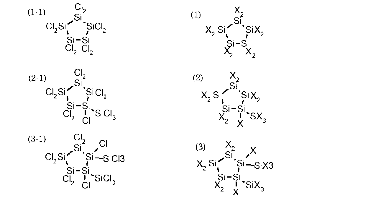
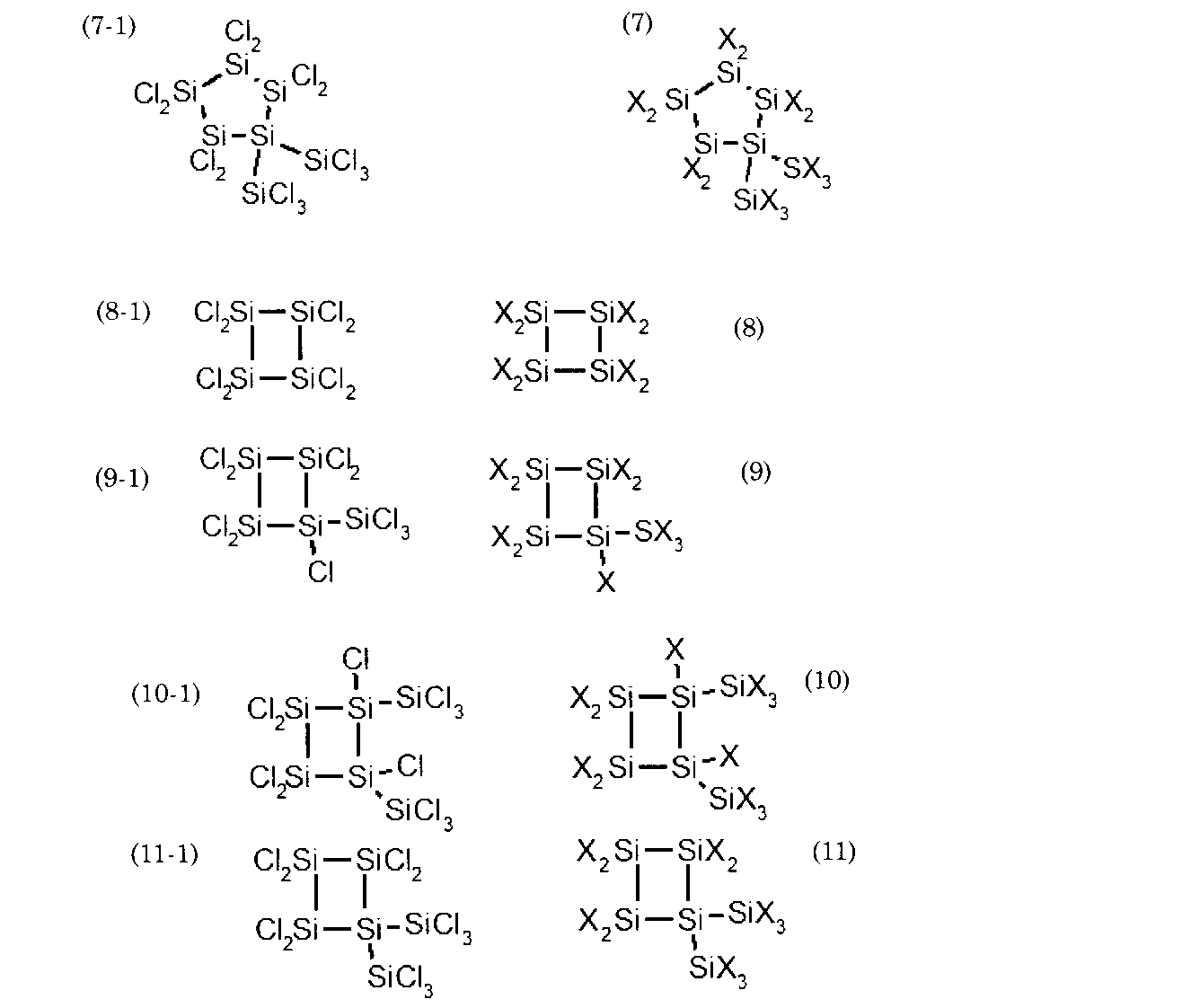
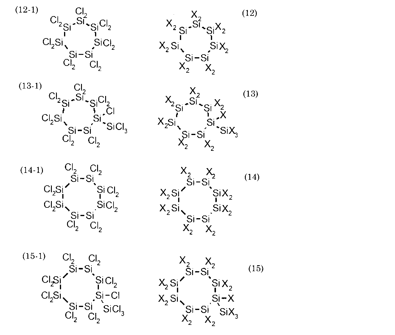
- the halosilanes having a cyclic structure include a 4-membered ring structure, a 5-membered ring structure, and a 6-membered ring structure other than the structural formulas (e) to (h), as shown in the following structural formulas (1) to (21): It may have a membered ring structure, an 8-membered ring structure, a multi-membered ring structure, or the like.
- X is at least one element selected from the group consisting of F, Cl, Br, and I.
- the structural formulas (1-1) to (21-1) below represent chlorosilanes in which the element X in the structural formulas (1) to (21) is chlorine.
- the halosilane having a cyclic structure contained in the by-product may be a monocyclic compound having a silicon ring composed of only silicon, as shown in the structural formulas (1) to (21).
- it may be an inorganic cyclic compound containing no carbon.
- the by-product may include a heterocyclic compound composed of silicon and oxygen.
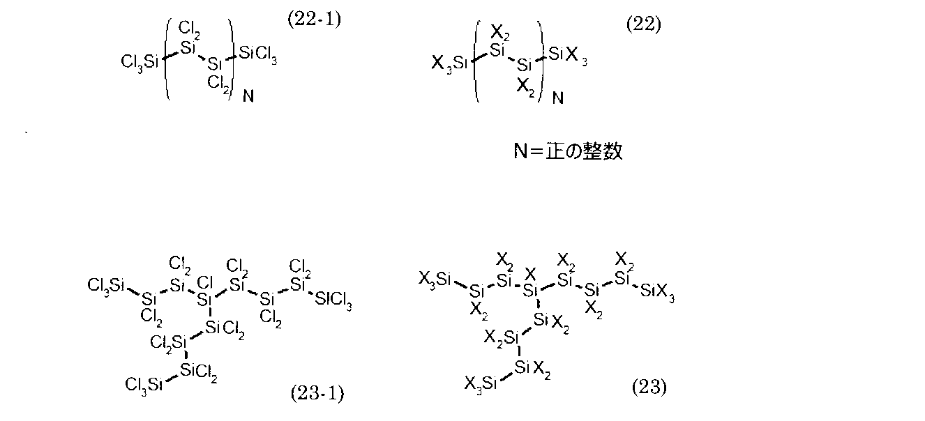
- the halosilanes having a chain structure that can be contained in the by-products are represented by, for example, the following structural formulas (22) and (23).
- N is, for example, a positive integer of 0 or more and 15 or less.
- X is at least one element selected from the group consisting of F, Cl, Br and I.
- the following structural formulas (22-1) and (23-1) represent chlorosilanes in which the element X in the structural formulas (22) and (23) is chlorine.
- the halosilane having a chain structure may be a straight chain compound without branching, as shown in the above structural formula (22). Further, the halosilane having a chain structure may be a chain compound having a branch, as shown in the structural formula (23). It can be estimated by mass spectrometry that the by-product contains halosilanes having a chain structure.
- the by-product generated by the method of depositing a silicon-containing material on a substrate using a gas containing silicon and a halogen may contain only halosilanes having a cyclic structure and has a chain structure. It may include only those having a ring structure, and may have both those having a cyclic structure and those having a chain structure.
- By-products can be produced by a method of depositing a silicon-containing material on a substrate using a gas containing silicon and halogen. Examples of such a method include a chemical vapor deposition (CVD) method such as an epitaxial growth method.
- CVD chemical vapor deposition
- FIG. 3 is a perspective view schematically showing an example of an epitaxial growth apparatus.
- the epitaxial growth apparatus 1 shown in FIG. 3 includes an apparatus body 10, an abatement device 20, and a connecting portion 30.
- the apparatus main body 10 includes a housing 11, a reaction chamber 12, an exhaust pipe 13, and a supply pipe (not shown).
- the reaction chamber 12, the discharge pipe 13, and the supply pipe are housed in the housing 11.
- One end of the supply pipe is connected to the reaction chamber 12.
- the other end of the supply pipe is connected to a source gas supply device (not shown).
- the discharge pipe 13 includes pipes 131 to 135.
- One end of the pipe 131 is connected to the reaction chamber 12.
- the other end of the pipe 131 is connected to one end of the pipe 132.
- the pipe 132 includes a reaction chamber independent valve (Chamber Isolation Valve: CIV).
- the other end of the pipe 132 is connected to one end of the pipe 133.
- the pipe 133 includes a pressure control valve (PCV).
- PCV pressure control valve
- the other end of the pipe 133 is connected to one end of the pipe 134.
- the other end of the pipe 134 is connected to one end of the pipe 135.
- the other end of the pipe 135 is connected to one end of a pipe 31 of the connecting portion 30 which will be described later.
- the connection part 30 includes a pipe 31 and a pipe 32. One end of the pipe 31 is connected to the other end of the pipe 135. The other end of the pipe 31 is connected to one end of the pipe 32. The other end of the pipe 32 is connected to the abatement device 20.
- the source gas is discharged from the source gas supply device and introduced into the reaction chamber 12 via the supply pipe.
- the raw material gas is a gas containing silicon and a halogen element. Therefore, the source gas contains one or more kinds of halogen elements and silicon.
- the gas containing silicon and a halogen element is, for example, a mixed gas of a compound containing a silicon and a halogen element and hydrogen. The concentration of hydrogen in this mixed gas is, for example, 95% by volume or more.
- the compound containing silicon and a halogen element is one or more compounds selected from the group consisting of a compound containing silicon and chlorine, a compound containing silicon and bromine, a compound containing silicon and fluorine, and a compound containing silicon and iodine. Is included.
- the compound containing silicon and a halogen element includes halosilanes.
- the compound containing silicon and chlorine is, for example, any one of chlorosilanes such as dichlorosilane (SiH 2 Cl 2 ), trichlorosilane (SiHCl 3 ) and tetrachlorosilane (SiCl 4 ), or a mixture thereof. is there.
- the mixed gas may contain at least one of monosilane (SiH 4 ) and hydrogen chloride (HCl).
- the compound containing silicon and bromine is, for example, any one kind of bromosilanes such as dibromosilane (SiH 2 Br 2 ), tribromosilane (SiHBr 3 ), and tetrabromosilane (SiBr 4 ), or It is a mixture of these.
- the mixed gas may contain at least one of monosilane (SiH 4 ) and hydrogen bromide (HBr).
- the raw material gas may contain two or more kinds of halogen elements, and the raw material gas may contain one or more kinds of halogen elements other than chlorine in addition to chlorine.
- the source gas is a mixed gas of a compound containing silicon and chlorine, hydrogen gas, and at least one of a compound containing a halogen element other than chlorine and a halogen gas other than chlorine gas.
- the compound containing a halogen element other than chlorine may or may not contain silicon.
- the source gas is a mixed gas of a compound containing a halogen element other than chlorine and silicon, hydrogen gas, and at least one of a compound containing chlorine and chlorine gas.
- the compound containing chlorine may or may not contain silicon.
- a base material is installed in the reaction chamber 12 under reduced pressure, and the base material is heated to a temperature equal to or higher than the reaction temperature with the raw material gas.
- the reaction temperature is 600° C. or higher in one example, and 1000° C. or higher in another example.
- a monocrystalline or polycrystalline silicon-containing film is formed on the base material by a thermochemical reaction.
- the base material is, for example, a single crystal silicon substrate.
- the exhaust gas exhausted from the reaction chamber 12 is introduced into the abatement device 20 via an exhaust path consisting of the exhaust pipe 13 and the connecting portion 30.
- the exhaust gas may include, among the compounds containing silicon and halogen contained in the raw material gas, those not deposited on the substrate, monosilane, hydrogen chloride and the like.
- the exhaust gas is burned in the abatement device 20 to be rendered harmless.
- the by-product may be deposited on the discharge pipe 13 and a part of the connection part 30. It is considered that the by-product is a solid or liquid obtained by polymerizing the components contained in the above-mentioned exhaust gas. The by-product is likely to deposit near the pipe 134 in the discharge pipe 13. In the pipes 131 to 133 located near the reaction chamber 12, the temperature of the exhaust gas is sufficiently high, and it is considered that the polymer is difficult to deposit. In addition, at the connecting portion located far from the reaction chamber 12, it is considered that the by-product is less likely to be generated because the amount of the component as the raw material of the by-product in the exhaust gas is small.
- the device in which the by-products including the above-mentioned halosilanes are generated in the discharge route is not limited to the above-mentioned epitaxial growth device.
- the raw material containing silicon and the raw material containing a halogen element are supplied to the reaction chamber by different routes.
- the raw material containing silicon may include powdery (solid) silicon.
- the source material containing a halogen element may be a source gas containing hydrogen halide such as hydrogen chloride.
- the silicon-containing substance forming apparatus of this embodiment no substrate such as a silicon substrate is provided in the reaction chamber. Then, in the reaction chamber, the raw material containing silicon and the raw material containing halogen element, which are separately introduced into each other, react with each other. A halosilane and hydrogen are produced by the reaction of a raw material containing silicon and a raw material containing a halogen element. Then, a silicon-containing substance is obtained by the reaction of halosilanes and hydrogen.
- the halosilanes produced by the reaction of the raw material containing silicon and the raw material containing a halogen element may include chlorosilanes such as trichlorosilane (SiHCl 3 ). Further, in the reaction in the reaction chamber, hydrogen halide, silicon tetrahalide and the like may be generated.
- the exhaust gas (exhaust substance) discharged from the reaction chamber contains halosilanes, and the halosilanes contained in the exhaust gas contain chlorosilanes such as the above-mentioned trichlorosilane.
- the exhaust gas from the reaction chamber may contain hydrogen and may also contain hydrogen halide, silicon tetrahalide and the like generated by the reaction in the reaction chamber.
- the hydrogen halide generated in the reaction in the reaction chamber may include hydrogen chloride (HCl).
- the silicon tetrahalide generated by the reaction in the reaction chamber may include silicon tetrachloride (SiCl 4 ).
- a cooling mechanism for cooling the exhaust gas is provided in the exhaust gas (exhaust substance) discharge path from the reaction chamber.
- the exhaust gas is liquefied by being cooled by the cooling mechanism. Then, the liquid substance (exhaust substance) in which the exhaust gas is liquefied is recovered.
- by-products can be deposited in the discharge route by liquefying the exhaust gas by the cooling mechanism.
- By-products may include a portion of the exhaust gas liquid that remains in the exhaust path without being recovered.
- the by-product may include a halosilane contained in the exhaust gas and a hydrolysis product of the halosilane.
- the hydrolysis product of halosilanes may be a solid substance.
- By-products may include silicon tetrahalide and the like contained in the exhaust gas. Further, in the discharge path, by-products are likely to precipitate, especially in the cooling mechanism and its vicinity.
- by-products containing halosilanes and the like can be deposited in the discharge route.
- By-products generated in the silicon-containing substance forming apparatus of this embodiment can also be transformed into explosive substances in the atmosphere. Therefore, also in the silicon-containing substance forming apparatus of the present example, the by-products are rendered harmless using the treatment liquid in the discharge route, as in any of the above-described embodiments and the like.
- the method for treating a by-product includes contacting the by-product with the treatment liquid to obtain the first solid matter.
- the treatment liquid contains water.
- hydrolysis of the by-product may occur.
- This hydrolysis can produce a solid hydrolysis product together with hydrogen halide such as hydrogen gas and hydrogen chloride (HCl).
- neutralization decomposition of the by-product When a by-product and a basic treatment liquid are contacted with each other, neutralization decomposition of the by-product may occur.
- solid-state neutralization decomposition products may be produced together with hydrogen gas and the like.
- hydrogen halide such as hydrogen chloride generated by the hydrolysis of the by-product can react with hydroxide ion in the treatment liquid to be neutralized.
- the first solid a hydrolysis product of a by-product or a neutralization decomposition product can be used.
- the first solid may be in the form of lumps or may be dispersed as fine particles in the treatment liquid.
- the present inventors have found that hydrolysis of a by-product with water cannot sufficiently detoxify the by-product. That is, the by-product hydrolysis product can be explosive and flammable. It is considered that the Si—Si bond remains in the hydrolysis with water. It is presumed that not all Si- ⁇ and Si-H bonds of the by-products are reacted in the hydrolysis of the by-products. Further, when a neutral aqueous solution is used, hydrogen halides such as hydrogen chloride produced cannot be neutralized, so that the pH of the treatment liquid after the reaction treatment becomes extremely low, which may be corrosive.
- the by-product when the by-product is neutralized and decomposed using a basic aqueous solution, the by-product can be sufficiently harmless. That is, the neutralization decomposition product of the by-product has neither explosiveness nor flammability. It is considered that this is because when the by-product and the basic aqueous solution are reacted, the Si—Si bond of the halosilane existing inside the by-product is neutralized and decomposed. Moreover, in the neutralization decomposition of the by-product, the Si- ⁇ bond and the Si-H bond of the by-product can be sufficiently broken.
- the hydrolysis product may include a compound having at least one of a siloxane bond (Si—O—Si, O—Si—O) and a silanol group (—Si—OH). Also, the hydrolysis product may include hydrosilanol groups (-Si(H)OH). The fact that the hydrolysis product has at least one of a siloxane bond and a silanol group can be estimated by the nuclear magnetic resonance spectroscopic analysis described below.
- this measurement sample is dispensed into a 3.2 mm zirconia sample tube (708239971) manufactured by JEOL Ltd.
- This NMR sample tube is set in the NMR spectroscopic analyzer, and the 29 Si NMR spectrum is measured.
- the NMR spectroscopic analysis device for example, JNM-ECA800 manufactured by JEOL Ltd. can be used.
- the number of times of integration is 4096 and the measurement range is ⁇ 250 ppm or more and 250 ppm or less.
- the peak appearing in the range of ⁇ 120 ppm or more and 10 ppm or less is considered to originate from at least one of the siloxane bond and the silanol group. Therefore, when it has a peak in this range, it can be presumed that the hydrolysis product has at least one of a siloxane bond and a silanol group.
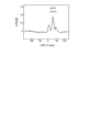
- FIG. 4 is a graph showing an example of 29 Si NMR spectrum relating to a hydrolysis product of a by-product.
- the horizontal axis represents chemical shift (ppm) and the vertical axis represents relative intensity.
- ppm chemical shift
- the vertical axis represents relative intensity.
- a peak with the highest relative intensity is detected at the position of ⁇ 70 ppm.
- the water used as the treatment liquid may be pure water, ion-exchanged water, purified water, tap water, or a mixture thereof.
- the basic treatment liquid may be water in which at least one of an inorganic base and an organic base is dissolved.
- the concentration of the inorganic base and the organic base is, for example, 0.01% by mass or more and 30% by mass or less, and preferably 0.1% by mass or more and 10% by mass or less.
- Examples of the inorganic base include metal hydroxides such as hydroxides of alkali metal elements and hydroxides of alkaline earth metal elements, alkali metals, carbonates of alkali metal elements and carbonates of alkaline earth metal elements. At least one selected from the group consisting of the following carbonates, hydrogen carbonates such as hydrogen carbonates of alkali metal elements, metal oxides, and ammonium hydroxide (NH 4 OH) is used.
- metal hydroxides such as hydroxides of alkali metal elements and hydroxides of alkaline earth metal elements, alkali metals, carbonates of alkali metal elements and carbonates of alkaline earth metal elements.
- metal hydroxide examples include lithium hydroxide, sodium hydroxide, potassium hydroxide, rubidium hydroxide, cesium hydroxide, calcium hydroxide, magnesium hydroxide, copper hydroxide, iron hydroxide, zinc hydroxide, and hydroxide. Aluminum or a mixture thereof.
- the alkali metal is, for example, a simple substance metal of potassium, a simple substance metal of lithium, a simple substance metal of sodium, or a mixture thereof.
- the carbonate is, for example, sodium carbonate, potassium carbonate, ammonium carbonate, potassium carbonate, lithium carbonate, barium carbonate, magnesium carbonate or a mixture thereof.
- the hydrogen carbonate is, for example, sodium hydrogen carbonate, ammonium hydrogen carbonate, potassium hydrogen carbonate, calcium hydrogen carbonate, or a mixture thereof.
- the metal oxide is, for example, calcium oxide, magnesium oxide, sodium oxide or a mixture thereof.
- Inorganic bases include sodium hydroxide (NaOH), potassium hydroxide (KOH), sodium carbonate (Na 2 CO 3 ), calcium hydroxide (Ca(OH) 2 ), lithium hydroxide (LiOH), sodium hydrogen carbonate. It is preferably at least one selected from the group consisting of (NaHCO 3 ) and ammonium hydroxide (NH 4 OH). Since such an inorganic base has low toxicity, by-products can be processed more safely by using such an inorganic base.
- the inorganic base is selected from the group consisting of potassium hydroxide (KOH), sodium carbonate (Na 2 CO 3 ), lithium hydroxide (LiOH), sodium hydrogen carbonate (NaHCO 3 ), and ammonium hydroxide (NH 4 OH). More preferably, it is at least one selected. When such an inorganic base is used, the reaction proceeds gently, so that the treatment can be performed more safely.
- KOH potassium hydroxide
- Na 2 CO 3 sodium carbonate
- LiOH lithium hydroxide
- NaHCO 3 sodium hydrogen carbonate
- NH 4 OH ammonium hydroxide
- organic base for example, at least one selected from the group consisting of alkylammonium hydroxides, organometallic compounds, metal alkoxides, amines, and heterocyclic amines is used.
- the alkylammonium hydroxide is, for example, tetramethylammonium hydroxide, tetraethylammonium hydroxide, choline hydroxide, or a mixture thereof.
- the organometallic compound is, for example, organolithium, organomagnesium, or a mixture thereof.
- Organolithium is, for example, butyllithium, methyllithium, or a mixture thereof.
- the organomagnesium is, for example, butylmagnesium, methylmagnesium, or a mixture thereof.
- the metal alkoxide is, for example, sodium ethoxide, sodium butoxide, potassium ethoxide, potassium butoxide, sodium phenoxide, lithium phenoxide, sodium ethoxide, sodium propoxide, sodium isopropoxide or a mixture thereof.
- the amine is methylamine, dimethylamine, trimethylamine, triethylamine, ethylenediamine, diethylamine, aniline or a mixture thereof.
- Heterocyclic amine is pyridine, pyrrolidine, imidazole, piperidine or a mixture thereof.
- the organic base is preferably at least one selected from the group consisting of sodium phenoxide (C 6 H 5 ONa), 2-hydroxyethyltrimethylammonium hydroxide (choline hydroxide), and tetramethylammonium hydroxide (TMAH). is there.
- the pH of the basic treatment liquid is preferably 8 or more and 14 or less before and after the treatment. Further, the pH of the basic treatment liquid before treatment is more preferably 9 or more and 14 or less, and further preferably 10 or more and 14 or less.
- the treatment liquid may contain optional components such as a surfactant and a pH buffer.
- the concentration of the surfactant in the treatment liquid is, for example, 0.01% by mass or more and 10% by mass or less, and preferably 0.1% by mass or more and 1% by mass or less.
- the surfactant includes, for example, at least one selected from the group consisting of anionic surfactants, cationic surfactants, amphoteric surfactants, and nonionic surfactants.
- the anionic surfactant is, for example, sodium laurate, sodium stearate, sodium lauryl sulfate, sodium 1-hexanesulfonate, lauryl phosphoric acid or a mixture thereof.
- the cationic surfactant is, for example, tetramethylammonium chloride, benzalkonium chloride, octyltrimethylammonium chloride, monomethylamine hydrochloride, butylpyridinium chloride or a mixture thereof.
- amphoteric surfactant is, for example, lauryl dimethylamino acetic acid betaine, cocamidopromyl betaine, sodium lauroyl glutamate, lauryl dimethylamine N-oxide or a mixture thereof.
- the nonionic surfactant is, for example, glycerin laurate, pentaethylene glycol onododecyl ether, polyoxyethylene sorbitan fatty acid ester, lauric acid diethanolamide, octyl glucoside, cetanol or a mixture thereof.
- the surfactant preferably contains at least one of benzalkonium chloride and sodium laurate, and more preferably benzalkonium chloride.
- the pH buffer plays a role of keeping the pH of the processing liquid constant during the processing of by-products.
- the pH buffer By using the pH buffer, it is possible to prevent the pH of the solution after the by-product treatment from becoming excessively high or excessively low. Therefore, by using the pH buffer, the by-products can be made safer in a safer manner.
- the concentration of the pH buffer in the treatment liquid is, for example, 0.01% by mass or more and 30% by mass or less, preferably 0.1% by mass or more and 10% by mass or less.
- pH buffer a mixture of a weak acid and its conjugate base, or a mixture of a weak base and its conjugate acid can be used.
- the pH buffering agent include a mixture of acetic acid (CH 3 COOH) and sodium acetate (CH 3 COONa), a mixture of citric acid and sodium citrate, or trishydroxymethylaminomethane (THAM) and ethylenediaminetetraacetic acid (EDTA) mixture is used.
- the judgment method of the treatment of the by-product is to judge the progress of the treatment of the by-product on the basis of the signal by the chemical analysis of at least one of the Si- ⁇ bond and the Si-H bond in the first solid substance. Including doing.
- the Si- ⁇ bond contained in the by-product can be cleaved by reacting with water and a basic aqueous solution. Further, the Si—H bond contained in the by-product can be cleaved by reacting with the basic aqueous solution. Therefore, the amount of Si- ⁇ and Si-H bonds in the by-products may decrease as the by-products process progresses. Therefore, the degree of progress of the treatment of the by-product is determined by using the signal obtained by the chemical analysis of at least one of the Si- ⁇ bond and the Si-H bond in the first solid, which is a reaction product of the by-product and the treatment liquid, as an index. Can be grasped. Thereby, the processing of the by-product can be managed.
- the method for determining the processing of the by-product may include setting in advance a threshold value that serves as a criterion for whether or not the processing of the by-product is completed. In this method, when the signal intensity of at least one of the Si- ⁇ bond and the Si-H bond of the first solid is less than or equal to a threshold value, it is determined that the by-product treatment is completed, and When it exceeds, it can be determined that the processing of the by-product is not completed.
- the method for determining the treatment of the by-product is as follows. After the contact between the by-product and the treatment liquid, the first solid matter is sampled at every elapse of a certain time, and the Si- It may include obtaining the intensity of the signal of at least one of the ⁇ bond and the Si—H bond. According to this method, the signal intensity of at least one of the Si- ⁇ bond and the Si-H bond in the first solid substance having a long contact time with the treatment liquid, and the Si-in the first solid substance having a short contact time with the treatment liquid. By comparing the intensity of the signal of at least one of the ⁇ bond and the Si—H bond and confirming the change over time, the progress of processing of the by-product can be grasped. Furthermore, by combining this method with the method of setting the above-mentioned threshold value, whether or not the treatment of the by-product is completed at each elapsed time, or whether the by-product is neutralized or hydrolyzed. Can be determined whether or not
- the signal derived from the Si- ⁇ bond or Si-H bond contained in the first solid substance can be obtained by various chemical analyses.
- this signal for example, the height, area, or full width at half maximum of the peak derived from the Si- ⁇ bond or the Si-H bond obtained by performing the chemical analysis on the first solid substance is used.
- These signals can be correlated with the content of Si- ⁇ or Si-H bonds. Therefore, the content of Si- ⁇ bond and Si-H bond remaining in the first solid can be estimated using the peaks derived from these bonds as an index.
- Examples of chemical analysis include Raman spectroscopic analysis, infrared spectroscopic analysis, and nuclear magnetic resonance spectroscopic analysis. Infrared spectroscopic analysis and nuclear magnetic resonance spectroscopic analysis will be described below as an example of a method for obtaining a signal derived from the Si—Cl bond. Raman spectroscopic analysis will be described as an example of a method of obtaining a signal derived from the Si—H bond.
- the first solid substance is collected from the mixture of the first solid substance and the treatment liquid.
- the collected first solid material is crushed using a fluororesin spatula.
- the crushed first solid is dried for 2 hours or more under reduced pressure of 5 Pa or less using a vacuum pump to obtain a measurement sample.
- At least a part of the first solid matter may be used as the measurement sample, and the drying treatment may be omitted. That is, the measurement sample may contain water or a basic aqueous solution.
- the measurement sample is subjected to infrared spectroscopic analysis once by the reflection-type ATR method to obtain an infrared spectroscopic spectrum.
- the infrared spectroscopic analyzer for example, FT/IR-6300 manufactured by JASCO Corporation is used.
- the prism for example, a diamond prism is used. In analysis, for example, the incident angle and 45 °, the measurement range and 400 cm -1 or more 4000 cm -1 or less, the resolution and 4 cm -1, the number of integration is 100 times. It is preferable to perform baseline correction and smoothing processing on the obtained infrared spectrum.
- the wave number is considered appears in the range of 800 cm -1 or more 900 cm -1 or less. It is considered that the absorbance I1 of the peak appearing within this range correlates with the amount of Si—Cl bonds contained in the first solid. That is, if the absorbance I1 of this peak is high, the amount of Si—Cl bonds contained in the first solid is large, and if the absorbance I1 is low, the amount of Si—Cl bonds contained in the first solid is small. it can. Peak intensity derived from the Si-Cl bond, the wave number can also be referred to as maximum value in the range of 800 cm -1 or more 900 cm -1 or less.
- the measurement specimen elapsed time is different by the wave number comparing the height of the absorbance I1 of maximum value in the range of 800 cm -1 or more 900 cm -1 or less.
- the progress of hydrolysis treatment or neutralization decomposition treatment can be controlled. That is, first, in the same manner as described above, the infrared spectroscopic spectrum of the first solid is obtained, and the maximum absorbance I1-1 is recorded. Next, the infrared spectroscopic spectrum is obtained for the first solid that has been in contact with the treatment liquid for a longer time, and the maximum absorbance I1-2 is recorded.
- the absorbance I1-2 is lower than the absorbance I1-1, it can be determined that the hydrolysis treatment or the neutralization decomposition treatment is proceeding. Further, for example, by repeating this operation at regular intervals, the absorbance I1 in the first solid matter becomes less than or equal to a threshold value, or at the time of disappearance from the infrared spectroscopy spectrum, the neutralization decomposition of the by-product is completed, It can be determined that the detoxification process for the by-products has been completed.
- the progress of the hydrolysis treatment or the neutralization decomposition treatment is compared.
- the infrared spectroscopic spectrum of the by-product collected under an inert atmosphere can be obtained by, for example, the microscopic reflection method.
- Judgment method example 1 by infrared spectroscopic analysis The present invention intensively studied, wave number a threshold for absorbance I1 maximum value in range of 800 cm -1 or more 900 cm -1, by setting as follows the progress of the processing of by-products It has been found that can be determined.
- Example 2 of determination method by infrared spectroscopy Further, as a result of earnest research, the present inventors have found that the absorbance I1 at the maximum value and the minimum value in the range of 900 cm ⁇ 1 or more and 1000 cm ⁇ 1 or less located on the higher wavenumber side than the absorbance I1 at the maximum value. It has been found that the progress of the process of the by-product can be determined by comparing the absorbance I2. Specifically, for the value (I1-I2) obtained by subtracting the absorbance I2 of the minimum value from the absorbance I1 of the maximum value, by setting a threshold value as shown below, the progress of the processing of the by-product is performed. Can be determined.
- the maximum absorbance I1 and the minimum absorbance I2 are the heights from the baseline.
- the baseline is the lowest absorbance in the infrared spectrum.
- a measurement sample is obtained by the same method as described in the determination method relating to infrared spectroscopic analysis.
- the measurement sample is subjected to microscopic laser Raman spectroscopic analysis to obtain a Raman spectrum.
- the microscopic laser Raman spectroscopic analyzer for example, NRS-5100MS manufactured by JASCO Corporation is used.
- the laser wavelength is 532 nm
- the resolution and 3.4cm -1 the number of integrations is 10 times
- the exposure time is 5 seconds .. It is preferable to perform baseline correction and smoothing processing on the obtained Raman spectrum.
- a peak derived from Si-H bond the Raman shift is considered appears in the range of 2000 cm -1 or 2500 cm -1 or less. It is considered that the intensity R1 of the peak appearing within this range correlates with the amount of Si—H bonds contained in the first solid. That is, if the intensity R1 of this peak is high, it is determined that the amount of Si—H bonds contained in the first solid is large, and if the intensity R1 is low, the amount of Si—H bonds contained in the first solid is small. it can. Peak intensity attributed to Si-H bonds, Raman shift can also be referred to as maximum value in the range of 2000 cm -1 or 2500 cm -1 or less.
- the Si-H bond can be an index showing the acidity of by-products. If many Si-H bonds remain in the first solid, it may indicate that the neutralization decomposition of the by-product is not sufficient. Therefore, by using the signal related to the Si—H bond as an index, the progress of neutralization decomposition of the by-product can be determined.
- the Raman shift is to compare the height of the strength R1 maxima in the range of 2000 cm -1 or 2500 cm -1 or less. That is, first, in the same manner as described above, the Raman spectrum of the first solid is obtained, and the maximum intensity R1-1 is recorded. Next, the Raman spectrum of the first solid that has been in contact with the treatment liquid for a longer period of time is obtained, and the maximum intensity R1-2 is recorded. If the strength R1-2 is lower than the strength R1-1, it can be determined that the hydrolysis treatment or the neutralization decomposition treatment is progressing.
- this operation is repeated at regular intervals, and when the intensity R1 of the first solid material disappears from the Raman spectrum, the neutralization decomposition of the by-product is completed and the detoxification treatment of the by-product is completed. You can judge that you are doing.
- the progress of the hydrolysis treatment or the neutralization decomposition treatment can be grasped.
- the intensity R1 of the first maximum value and the intensity R2 of the second maximum value are heights from the baseline.
- the baseline is a line connecting the spectra of the portion that is estimated to have no peak.
- the peak attributed to the Si—Cl bond appears within the range of ⁇ 40 ppm to 10 ppm according to one example, and within the range of ⁇ 10 ppm to 5 ppm according to another example. .. It is considered that the intensity of this peak correlates with the amount of Si—Cl bonds contained in the first solid. That is, if the intensity of this peak is high, it can be determined that the amount of Si—Cl bonds contained in the first solid is large, and if the intensity is low, the amount of Si—Cl bonds contained in the first solid is small.
- the determination method described above may be performed by combining a plurality of chemical analyses. For example, by combining the infrared spectroscopic analysis and the Raman spectroscopic analysis described above, it is possible to more accurately determine the progress of the processing of the by-product.
- the determination method using the signal of at least one of the Si- ⁇ bond and the Si-H bond as an index and the method using the pH of the treatment liquid as an index may be combined. That is, as described above, when the by-product and the treatment liquid are brought into contact with each other, hydrogen halide such as hydrogen chloride (HCl) may be generated. Therefore, the pH of the treatment liquid in the mixture of the first solid matter and the treatment liquid can be lowered. When the hydrogen halide such as hydrogen chloride is sufficiently neutralized, it is considered that the treatment liquid in the mixture of the first solid and the treatment liquid has a pH higher than 7.
- the pH of the treatment liquid in the mixture of the first solid and the treatment liquid is higher than 7, it can be determined that the hydrogen halide such as hydrogen chloride in the treatment liquid is neutralized. Further, when the pH of the treatment liquid in the mixture of the first solid and the treatment liquid is 12 or more, it can be determined that hydrogen halide such as hydrogen chloride in the treatment liquid is sufficiently neutralized.
- the above-described determination method using the signal of at least one of the Si- ⁇ bond and the Si-H bond as an index and the method using the temperature rise of the treatment liquid as an index may be combined. That is, when the by-product and the treatment liquid are brought into contact with each other, the temperature of the treatment liquid may rise in the mixture of the by-product and the treatment liquid due to the neutralization decomposition reaction or the hydrolysis reaction of the by-product. Therefore, the temperature difference between the treatment liquid before contacting with the by-product and the treatment liquid after contacting with the by-product can be an index for determining the progress of treatment of the by-product. For example, the temperature of the treatment liquid in the mixture of the by-product and the treatment liquid is continuously measured, and while the temperature is rising, it can be determined that neutralization decomposition or hydrolysis of the by-product is in progress. ..
- the safety of processing by-products can be judged. For example, in the case where neither the temperature increase nor the pH decrease of the treatment liquid occurs in the mixture of the by-product and the treatment liquid, there is a sufficient amount of the base with respect to the by-product, and the neutralization decomposition of the by-product Can be determined to have been sufficiently performed.
- the determination method according to the embodiment described above uses the signal of at least one of the Si- ⁇ bond and the Si-H bond of the first solid as an index. Therefore, the progress of the processing of the by-product can be determined.
- a by-product is brought into contact with a treatment liquid containing water to obtain a first solid matter, and at least one of the Si— ⁇ bond and the Si—H bond chemistry of the first solid matter. Determining the progress of processing of the by-product based on the signal from the analysis.
- the treatment liquid the above-mentioned water and basic aqueous solution can be used.
- the end point of the by-product can be managed by combining the method for treating the by-product with the treatment liquid with the determination method according to the above-described embodiment. According to such a method, it is possible to prevent the by-product from being accidentally taken out before the detoxification process of the by-product is completed, and the worker can perform the by-product processing work more safely. You can Further, since it is possible to prevent an excessive base from being added and an excessive work time to be required for treating the by-product, it is possible to enhance the efficiency of the treatment of the by-product.
- the treatment method according to the embodiment may include stopping the treatment of the by-product when the intensity of the signal is equal to or less than the threshold value.
- the treatment liquid may be further added to the mixture of the first solid substance and the treatment liquid.
- the mixture of the first mixture and the treatment liquid may be left for a certain period of time in order to sufficiently react the by-product and the treatment liquid.
- the treatment liquid may further include a basic aqueous solution having a higher pH.
- the processing method according to the embodiment includes the above-mentioned 3-1-1) determination method example 1 by infrared spectroscopic analysis, 3-1-2) determination method example 2 by infrared spectroscopic analysis, and 3-2-1)
- 3-1-1) determination method example 1 by infrared spectroscopic analysis 3-1-2
- determination method example 2 by infrared spectroscopic analysis 3-2-1
- a processing method when the determination method examples by Raman spectroscopic analysis are combined will be described below.
- Absorbance I1 is greater than 0.050 and 0.10 or less, and it is determined that a part of the treatment of the by-product is not completed: the mixture of the first solid substance and the treatment liquid is treated. Add more liquid. Alternatively, the mixture of the first mixture and the treatment liquid is allowed to stand for a certain period of time in order to sufficiently react the by-product and the treatment liquid. Alternatively, a basic aqueous solution having a higher pH is further added as a treatment liquid. After that, it is preferable to further perform infrared spectroscopic analysis on the first solid to confirm the absorbance I1. The determination by the further infrared spectroscopic analysis is preferably repeated until the absorbance I1 becomes 0.050 or less.
- the treatment liquid is further added to the mixture of the solid matter and the treatment liquid.
- the mixture of the first mixture and the treatment liquid is allowed to stand for a certain period of time in order to sufficiently react the by-product and the treatment liquid.
- a basic aqueous solution having a higher pH is further added as a treatment liquid.
- the first solid substance is further subjected to infrared spectroscopic analysis to confirm the absorbance I1 and the value (I1-I2).
- the determination by the further infrared spectroscopic analysis is preferably repeated until the value (I1-I2) becomes 0.001 or less.
- the treatment liquid is further added to the mixture of the first solid substance and the basic aqueous solution. to add.
- the mixture of the first mixture and the treatment liquid is allowed to stand for a certain period of time in order to sufficiently react the by-product and the treatment liquid.
- a basic aqueous solution having a higher pH is further added as a treatment liquid.
- the treatment method according to the embodiment may be performed in two steps, ie, pretreatment with water as a by-product and main treatment with a basic aqueous solution.
- This treatment method comprises: contacting the by-product with water to obtain a second solid, contacting the second solid with a basic aqueous solution to obtain a third solid, and regarding the third solid. Determining the progress of processing of the by-product based on the signal from the chemical analysis of at least one of the Si- ⁇ bond and the Si-H bond.
- the second solid may be a hydrolysis product of a by-product.
- the third solid may be a neutralization decomposition product of a by-product.
- the treatment method may further include contacting the second solid with the basic aqueous solution based on a signal from the chemical analysis of at least one of the Si- ⁇ bond and the Si-H bond in the second solid.
- the by-product can be treated more gently.
- the processing method according to the embodiment includes the above-mentioned 3-1-1) determination method example 1 by infrared spectroscopic analysis, 3-1-2) determination method example 2 by infrared spectroscopic analysis, and 3-2-1)
- 3-1-1) determination method example 1 by infrared spectroscopic analysis 3-1-2
- determination method example 2 by infrared spectroscopic analysis 3-2-1
- a processing method when the determination method examples by Raman spectroscopic analysis are combined will be described below.
- Absorbance I1 of the second solid is greater than 0.050 and 0.10 or less, and one of the detoxification treatments of by-products If part is determined to be incomplete: To the mixture of second solid and water, further basic aqueous solution is added to obtain a third solid.
- the value (I1-I2) of the second solid is larger than 0.001 and the absorbance I2 of the minimum value is larger than 0.130, and the detoxification treatment of the by-product is not completed. If yes: add more water to the mixture of second solid and water. Alternatively, the mixture of the second mixture and water is left to stand in order to sufficiently react the by-product with water. Alternatively, a basic aqueous solution is further added to the mixture of the second solid and water to obtain the third solid. Then, it is preferable to further perform infrared spectroscopy on the second solid or the third solid to confirm the absorbance I1 and the value (I1-I2). The determination by the further infrared spectroscopic analysis is preferably repeated until the value (I1-I2) becomes 0.001 or less.
- the value (I1-I2) of the third solid is larger than 0.001 and the absorbance I2 of the minimum value is 0.130 or less, and the treatment of the by-product is not partially completed.
- the value (I1-I2) was larger than 0.001 and the minimum absorbance I2 was larger than 0.130, it was judged that the detoxification treatment of the by-product was not completed.
- a basic aqueous solution is further added to the mixture of the third solid and the basic aqueous solution.
- the mixture of the third mixture and the basic aqueous solution is allowed to stand.
- a basic aqueous solution having a higher pH is further added.
- the treatment method according to the embodiment is used in combination with a method using the pH of the treatment liquid as an index, in addition to the determination method using the signal of at least one of the Si- ⁇ bond and the Si-H bond as an index.
- a method using the temperature change of the treatment liquid as an index may be used in combination. That is, in the above-described method, in addition to the signal intensity being equal to or less than the threshold value, the temperature change of the treatment liquid in the mixture of the first solid matter or the third solid matter and the treatment liquid was measured, and the temperature change stopped. At a point of time, or when the temperature rise stops and the temperature starts to decrease, the by-product treatment may be stopped.
- the treatment liquid in the mixture of the first solid matter or the third solid matter and the treatment liquid is higher than the temperature before mixing with the by-product by a specified temperature
- the treatment liquid may be further added.
- a treatment liquid having a higher pH may be added.
- the treatment method according to the embodiment includes ultrasonic treatment of a mixture of the first solid and the treatment liquid, a mixture of the second solid and water, or a mixture of the third solid and the basic aqueous solution. It may include performing a pulverization process.
- the processing method according to the embodiment described above uses the determination method according to the embodiment. Therefore, by using the processing method according to the embodiment, the by-product can be processed more safely and efficiently.
- a source gas was introduced into an epitaxial growth apparatus and reacted with a silicon substrate at a temperature of 800° C. to form a single crystal silicon film on the silicon substrate.
- a mixed gas in which dichlorosilane and hydrogen chloride were mixed with hydrogen gas was used as the raw material gas. The concentration of hydrogen in the mixed gas was 95% by volume or more.
- the pipe of the epitaxial growth apparatus was disassembled in a nitrogen atmosphere, and the by-products were collected and used as Sample A.
- the by-product was a white creamy liquid.
- the collected by-product was analyzed by nuclear magnetic resonance spectroscopy and mass spectrometry, it was confirmed that it contained chlorosilanes having a cyclic structure which is considered to correspond to the above structural formulas (e) to (h). ..
- a second petri dish 1.0 mL of the basic aqueous solution was added and brought into contact with the by-product to obtain a mixture of the first solid and the basic aqueous solution. After the lapse of 60 minutes, the first solid substance was taken out of the mixture and dried to obtain a sample C. This treatment was performed using a thermometer while measuring the temperature in the treatment liquid.
- a solution prepared by dissolving tetramethylammonium hydroxide (TMAH) in water was used as the basic aqueous solution. In the basic aqueous solution, the TMAH concentration was 0.5% by mass, and the pH was 12.
- the by-product in the third petri dish was left in the draft chamber in the air atmosphere for 60 minutes to react the by-product with air to obtain the first solid.
- This first solid was designated as Sample D.
- Samples B to D have explosiveness and flammability by the following method. First, the sample was placed in a metal container. The SUS spatula was pressed against the sample in the metal container and moved to visually confirm whether or not the first solid matter ignites. When the first solid matter ignites, it is determined that the first solid matter has an explosive property, and when the first solid matter does not ignite, it is determined that the first solid matter does not have an explosive property. did.
- the first solid has neither explosiveness nor flammability, it is determined that the detoxification treatment is completed, and if it has either explosiveness or flammability, detoxification is performed. It was judged that a part of the treatment was not completed, and when it had both explosiveness and flammability, it was determined that the detoxification treatment was not completed.
- the sample A was assumed to have both explosiveness and flammability. The results of this determination are shown in Table 1.
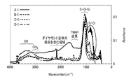
- FIG. 5 is a graph showing an example of infrared spectroscopy spectra of Samples A to D.
- FIG. 5 is a graph showing an example of infrared spectroscopy spectra of Samples A to D.
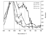
- FIG. 6 is an enlarged graph of a part of the graph shown in FIG. 5 and 6, the horizontal axis represents the wave number and the vertical axis represents the absorbance.
- AI, BI, CI and DI indicate the infrared spectroscopy spectra of sample A, sample B, sample C and sample D, respectively.
- the absorbance at the baseline is 0.
- the peak appearing in the range of 2900 cm -1 or 3700 cm -1 or less was derived from the hydroxyl (-OH), an peak appearing in the range of 2700 cm -1 or 3000 cm -1 or less, methyl derived based on (-CH 3), 2000cm -1 or 2400 cm -1 the following range is a region including the absorption of the diamond prism itself, the peak appearing in the range of 1500 cm -1 or 1700 cm -1 or less, TMAH derived from the peak appearing in the range of 900 cm -1 or more 1300 cm -1 or less was derived from Si-O-Si bond peak appearing in the range of 800 cm -1 or more 900 cm -1 or less, Si-Cl bond It is thought to be derived from.
- the peak related to the Si—Cl bond is circled.
- points P1 and P2 indicate the maximum value I1 and the minimum value I2 of the sample A, respectively.
- points P3 and P4 indicate the maximum value I1 and the minimum value I2 of the sample B, respectively.
- points P5 and P6 indicate the maximum value I1 and the minimum value I2 of the sample D, respectively.
- Sample C the absorbance at the maximum value I1 and the absorbance at the minimum value I2 were equal.
- the maximum value I1, the minimum value I2, and the value (I1-I2) are calculated from each infrared spectrum, and the samples A to D are made harmless based on the determination method examples 1 and 2 by infrared spectroscopy described above. It was determined whether the treatment was completed. The results are shown in Table 2.
- FIG. 7 is a graph showing an example of Raman spectra of Samples A to D.
- FIG. 8 is a graph obtained by enlarging a part of the graph shown in FIG. 7. 7 and 8, the horizontal axis represents the Raman shift and the vertical axis represents the intensity.
- AR, BR, CR and DR represent Raman spectra of Sample A, Sample B, Sample C and Sample D, respectively.
- the peak appearing in the range of 3200cm -1 or 3800 cm -1 or less was derived from the hydroxyl group (-OH), 1400 cm -1 or 1600 cm -1 in the range and 2700 cm -1 or 3200cm It is considered that the peak appearing in the range of -1 or less originates from the methyl group (-CH 3 ), and the peak appearing in the range of 2000 cm -1 to 2500 cm -1 originates from the Si-H bond. In FIG. 7, the peak related to the Si—H bond is circled.
- the column labeled “treatment method” describes the characteristics when each sample was prepared.
- the columns labeled “explosive” and “flammability” the results of the explosive and flammability confirmation test for each sample are listed.
- Pre-treatment pH the pH of water and the basic treatment liquid used in the treatment of the by-product are described.
- post-treatment pH the pH of water or the basic aqueous solution in the mixture of the first solid and water or the basic aqueous solution is described.
- maximum temperature (° C.) the highest temperature reached by the processing liquid that is processing the by-product is described.
- each sample was incomplete when it had explosiveness and flammability, and partially unfinished when it had explosiveness and flammability. It is described as completed when neither completed nor explosive nor flammable.
- the column labeled “treatment method” describes the characteristics of each sample when it was prepared.
- the absorbance I1 of the value is described.
- the column labeled “Judgment” when the maximum absorbance I1 is 0.050 or less, the process is completed, and when the maximum absorbance I1 is greater than 0.050 and 0.10 or less. Describes as partially incomplete, and incomplete when the maximum absorbance I1 is greater than 0.10.
- the column labeled “I2” indicates that the wave number in the infrared spectrum of each sample is 900 cm ⁇ 1 or more and 1000 cm ⁇ 1 or less.
- the absorbance I2 at the minimum value of the range is shown.
- the value obtained by subtracting the minimum absorbance I2 from the maximum absorbance I1 is shown.
- judgment it is completed when the value (I1 ⁇ I2) is 0.001 or less, and the value (I1 ⁇ I2) is larger than 0.001 and is a minimum value. If the absorbance I2 is 0.130 or less, it means that the value is not completed and the value (I1-I2) is greater than 0.001, and if the minimum absorbance I2 is greater than 0.130, the value is uncompleted. It is described as completed.
- the column labeled “treatment method” describes the characteristics of each sample prepared.
- the column denoted by “R1” in the Raman spectrum of each sample Raman shift of the maximum value of the range of 2000 cm -1 or 2500 cm -1 or less The strength is described.
- the column denoted by “R2”, in the Raman spectrum of each sample Raman shift describes the intensity of a peak derived from OH group appearing in the range of 2700 cm -1 or 3500 cm -1.
- R1/R2 the ratio of the intensity R1 of the maximum value and the intensity R2 of the peak derived from the OH group is described.
- judgment it is described as completed when the ratio R1/R2 is 1/5 or less, and incomplete when the ratio R1/R2 is greater than 1/5.
- the determination method according to the embodiment described above uses the signal of at least one of the Si- ⁇ bond and the Si-H bond of the first solid as an index. Therefore, the progress of the processing of the by-product can be determined.
Landscapes
- Chemical & Material Sciences (AREA)
- Physics & Mathematics (AREA)
- Organic Chemistry (AREA)
- Health & Medical Sciences (AREA)
- Engineering & Computer Science (AREA)
- Chemical Kinetics & Catalysis (AREA)
- General Physics & Mathematics (AREA)
- High Energy & Nuclear Physics (AREA)
- Immunology (AREA)
- Pathology (AREA)
- Biochemistry (AREA)
- General Health & Medical Sciences (AREA)
- Life Sciences & Earth Sciences (AREA)
- Analytical Chemistry (AREA)
- Materials Engineering (AREA)
- Metallurgy (AREA)
- Spectroscopy & Molecular Physics (AREA)
- General Chemical & Material Sciences (AREA)
- Crystallography & Structural Chemistry (AREA)
- Medicinal Chemistry (AREA)
- Bioinformatics & Cheminformatics (AREA)
- Mechanical Engineering (AREA)
- Inorganic Chemistry (AREA)
- Nuclear Medicine, Radiotherapy & Molecular Imaging (AREA)
- Condensed Matter Physics & Semiconductors (AREA)
- Silicon Compounds (AREA)
- Investigating Or Analysing Materials By Optical Means (AREA)
- Chemical Vapour Deposition (AREA)
- Treating Waste Gases (AREA)
Abstract
Description
ケイ素及びハロゲンを含むガスを用いて、基材上にケイ素含有物を堆積させる方法により生じる副生成物を処理する方法としては、副生成物と水とを接触させて副生成物を加水分解する方法が提案されている。また、本発明者らによって、副生成物と塩基性水溶液とを接触させて副生成物を中和分解する方法が提案されている。
副生成物は、例えば、固形状、液体状、ペースト状又はクリーム状の形態にある。副生成物は、水や酸素と反応して、爆発性及び発火性を有する物質を生じ得る。副生成物は、Si-α結合又はSi-H結合の少なくとも一方を含む化合物であると考えられる。副生成物がSi-H結合又Si-α結合を含むことは、例えば、ラマン分光分析、赤外分光分析、核磁気共鳴(NMR)分光分析、又は、X線分析などの化学分析により確認できる。なお、副生成物について分析を行う際には、不活性雰囲気下で採取した副生成物を、酸素や水と接触しないように、不活性雰囲気下で調製した測定試料を用いる。







副生成物の処理方法は、副生成物と処理液とを接触させて、第1固形物を得ることを含む。処理液は、水を含む。
副生成物の処理の判定方法は、第1固形物についてのSi-α結合及びSi-H結合の少なくとも一方の化学分析によるシグナルに基づいて、副生成物の処理の進行を判定することを含む。
先ず、第1固形物と処理液との混合物から第1固形物を採取する。採取した第1固形物を、フッ素樹脂製のスパチュラを用いて粉砕する。粉砕後の第1固形物を、真空ポンプを用いて5Pa以下の減圧下、2時間以上にわたって乾燥させて測定試料を得る。測定試料としては、第1固形物の少なくとも一部を用いればよく、乾燥処理は省略してもよい。すなわち、測定試料は、水又は塩基性水溶液を含んでいてもよい。
本発明者らは、鋭意研究の結果、波数が800cm-1以上900cm-1以下の範囲における極大値の吸光度I1に関する閾値を、次のように設定することにより、副生成物の処理の進行度を判定できることを見出している。
更に、本発明者らは、鋭意研究の結果、極大値の吸光度I1と、極大値の吸光度I1よりも高波数側に位置し、波数が900cm-1以上1000cm-1以下の範囲における極小値の吸光度I2とを比較することにより、副生成物の処理の進行度を判定できることを見出している。具体的には、極大値の吸光度I1から、極小値の吸光度I2を差し引いて得られる値(I1-I2)について、下記に示すように閾値を設定することにより、副生成物の処理の進行度を判定できる。
先ず、赤外分光分析に係る判定方法で説明したのと同様の方法で、測定試料を得る。次に、測定試料について顕微レーザーラマン分光分析を行い、ラマンスペクトルを得る。顕微レーザーラマン分光分析装置としては、例えば、日本分光株式会社製のNRS-5100MSを用いる。分析に際しては、例えば、レーザー波長を532nmとし、測定範囲を8.2cm-1以上4000cm-1以下とし、分解能を3.4cm-1とし、積算回数を10回とし、露光時間を5秒とする。得られたラマンスペクトルについて、ベースライン補正及びスムージング処理を行うことが好ましい。
また、本発明者らは、鋭意研究の結果、ラマンシフトが2000cm-1以上2500cm-1以下の範囲の第1極大値の強度R1と、ラマンシフトが2700cm-1以上3500cm-1以下の範囲の第2極大値の強度R2とを比較することにより、副生成物の処理の進行度を判定できることを見出している。ラマンシフトが2700cm-1以上3500cm-1以下の範囲の第2極大値は、ヒドロキシル基(-OH)、又は、有機塩基に含まれるメチル基(-CH3)に由来するピークに対応すると考えられる。具体的には、強度R1と強度R2との比R1/R2について、下記に示すように閾値を設定することにより、副生成物の処理の進行度を判定できる。
測定試料としては、例えば、0.2gの乾燥させた第1固形物と、2mLの脱水重トルエン(関東化学製:製品番号21744-1A)とを混合し、この混合物を4時間にわたって静置したものを用いる。この測定試料を株式会社ハルナ製J.YOUNGバルブ付き試料管(S-5-600-JY-8)に分取して、このNMR試料管をNMR分光分析装置内にセットし、29Si NMRスペクトルを測定する。NMR分光分析装置としては、例えば、JEOL社製JNM-ECA800を用いることができる。29Si NMRスペクトルの測定に際しては、例えば、積算回数を3500回とし、測定範囲を-500ppm以上500ppm以下とする。
以上説明した判定方法は、複数の化学分析を組み合わせて行ってもよい。例えば、上述した赤外分光分析とラマン分光分析とを組み合わせることにより、副生成物の処理の進行をより正確に判定できる。
実施形態に係る処理方法は、副生成物に水を含む処理液を接触させて第1固形物を得ることと、第1固形物についてのSi-α結合及びSi-H結合の少なくとも一方の化学分析によるシグナルに基づいて、副生成物の処理の進行を判定することとを含む。処理液としては、上述した水及び塩基性水溶液を用いることができる。
(1)吸光度I1が0.050以下であり、副生成物の無害化処理が完了したと判定された場合:副生成物の処理を停止する。その後、処理液と第1固形物との混合物内から、第1固形物を取り出して、第1固形物を焼却する又は廃棄する処理を更に行ってもよい。
(1)値(I1-I2)が、0.001以下であり、副生成物の無害化処理が完了していると判定された場合:副生成物の処理を停止する。その後、処理液と第1固形物との混合物内から、第1固形物を取り出して、第1固形物を焼却する又は廃棄する処理を更に行ってもよい。
(1)比R1/R2が、1/5以下であり、副生成物の無害化処理が完了していると判定された場合:副生成物の処理を停止する。その後、処理液と第1固形物との混合物内から、第1固形物を取り出して、第1固形物を焼却する又は廃棄する処理を更に行ってもよい。
実施形態に係る処理方法は、副生成物の水による前処理と、塩基性水溶液による本処理との2段階に分けて行われてもよい。この処理方法は、副生成物に水を接触させて第2固形物を得ることと、第2固形物に塩基性水溶液を接触させて第3固形物を得ることと、第3固形物についてのSi-α結合及びSi-H結合の少なくとも一方の化学分析によるシグナルに基づいて、副生成物の処理の進行を判定することとを含み得る。第2固形物は、副生成物の加水分解生成物であり得る。また、第3固形物は、副生成物の中和分解生成物であり得る。
(1)第2固形物の吸光度I1が0.050より大きく0.10以下であり、副生成物の無害化処理の一部が完了していないと判定された場合:第2固形物と水との混合物に、塩基性水溶液を更に追加して、第3固形物を得る。
(1)第2固形物の値(I1-I2)が、0.001より大きく、かつ、極小値の吸光度I2が0.130以下であり、副生成物の処理の一部が完了していないと判定された場合:第2固形物と水との混合物に、塩基性水溶液を更に追加して、第3固形物を得る。
(1)第2固形物の比R1/R2が、1/5より大きく、副生成物の無害化処理が完了していないと判定された場合:第2固形物と水との混合物に、塩基性水溶液を更に追加して、第3固形物を得る。
実施形態に係る処理方法は、上述したSi-α結合及びSi-H結合の少なくとも一方のシグナルを指標として用いる判定方法に加えて、処理液のpHを指標とする方法を組み合わせて利用してもよい。すなわち、上述した方法において、シグナルの強度が閾値以下であることに加えて、第1固形物又は第3固形物と処理液との混合物中の処理液のpHが、7より大きい場合、あるいは、12以上である場合に、副生成物の処理を停止してもよい。また、第1固形物又は第3固形物と処理液との混合物中の処理液のpHが、12より低い、あるいは、7以下である場合に、混合物に塩基性水溶液を更に加える処理を行ってもよい。
先ず、原料ガスをエピタキシャル成長装置に導入して、800℃の温度でシリコン基板と反応させて、シリコン基板上に単結晶シリコン膜を形成した。原料ガスとしては、水素ガスに、ジクロロシランと塩化水素とを混合した混合ガスを用いた。混合ガスにおける水素の濃度は、95体積%以上であった。
試料B~Dについて、以下の方法により、爆発性及び燃焼性を有するか否かを確認した。先ず、試料を、金属容器内に入れた。金属容器内の試料に、SUS製のスパチュラを押し当てながら動かして、第1固形物が発火するか否かを目視で確認した。第1固形物が発火した場合には、第1固形物は爆発性を有すると判定し、第1固形物が発火しなかった場合には、第1固形物は爆発性を有さないと判定した。
副生成物の処理前の水及び塩基性水溶液のpH、及び、第1固形物と水若しくは塩基性水溶液との混合物中の水若しくは塩基性水溶液のpHを、pH試験紙を用いて測定した。この結果を、表1に示す。
試料B~Dについて、上述した条件で赤外分光分析を行い、各試料の赤外分光スペクトルを得た。また、試料Aについて、顕微IR法により赤外分光スペクトルを得た。なお、アクセサリとしては日本分光株式会社製IRT-7000を用い、測定範囲は650cm-1以上4000cm-1以下とし、分解能を4cm-1とし、積算回数を100回とした。その結果を図5及び図6に示す。図5は、試料A~Dに係る赤外分光スペクトルの一例を示すグラフである。図6は、図5に示すグラフの一部を拡大したグラフである。図5及び図6において、横軸は波数を示し、縦軸は吸光度を示している。図5及び図6において、A-I、B-I、C-I及びD-Iは、それぞれ、試料A、試料B、試料C及び試料Dの赤外分光スペクトルを示している。図5及び図6に示す赤外分光スペクトルにおいて、ベースラインの吸光度は0である。
試料A~Dについて、上述した条件でラマン分光分析を行い、各試料のラマンスペクトルを得た。その結果を図7及び図8に示す。図7は、試料A~Dに係るラマンスペクトルの一例を示すグラフである。図8は、図7に示すグラフの一部を拡大したグラフである。図7及び図8において、横軸はラマンシフトを示し、縦軸は強度を示している。図7及び図8において、A-R、B-R、C-R及びD-Rは、それぞれ、試料A、試料B、試料C及び試料Dのラマンスペクトルを示している。


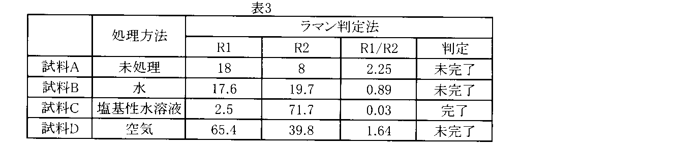
Claims (13)
- ケイ素及びハロゲンを含む物質を反応させる、或いは、ケイ素を含む物質とハロゲンを含む物質とを反応させる工程において生じる副生成物の処理の進行を判定する判定方法であって、
前記副生成物の処理は、前記副生成物に水を含む処理液を接触させて第1固形物を得ることを含み、
前記判定方法は、前記第1固形物についてのSi-α結合(αはF、Cl、Br、及びIからなる群より選ばれる少なくとも1種である)及びSi-H結合の少なくとも一方の化学分析によるシグナルに基づいて、前記副生成物の処理の進行を判定することを含む判定方法。 - 前記シグナルの強度が、閾値以下である場合には、前記副生成物の処理が完了していると判定し、前記閾値を超える場合には、前記副生成物の処理が完了していないと判定することを含む請求項1に記載の判定方法。
- 前記化学分析は、赤外分光分析である請求項1又は2に記載の判定方法。
- 前記化学分析は、ラマン分光分析である請求項1又は2に記載の判定方法。
- 前記化学分析は、核磁気共鳴分光分析である請求項1又は2に記載の判定方法。
- 前記第1固形物の赤外分光スペクトルにおいて、波数が800cm-1以上900cm-1以下の範囲の極大値の吸光度I1が、0.050以下である場合には、前記副生成物の処理が完了していると判定し、
前記極大値の吸光度I1が、0.050より大きく0.10以下である場合には、前記副生成物の処理の一部が完了していないと判定し、
前記極大値の吸光度I1が、0.10より大きい場合には、前記副生成物の処理が完了していないと判定することを含む請求項3に記載の判定方法。 - 前記第1固形物の赤外分光スペクトルにおいて、波数が800cm-1以上900cm-1以下の範囲の極大値の吸光度I1から、波数が900cm-1以上1000cm-1以下の範囲の極小値であって、前記極大値よりも高波数側に位置する極小値の吸光度I2を差し引いた値(I1-I2)が0.001以下である場合には、前記副生成物の処理が完了していると判定し、
前記値(I1-I2)が0.001より大きく、かつ、前記極小値の吸光度I2が0.130以下である場合には、前記副生成物の処理の一部が完了していないと判定し、
前記値(I1-I2)が0.001より大きく、かつ、前記極小値の吸光度I2が0.130より大きい場合には、前記副生成物の処理が完了していないと判定することを含む請求項3に記載の判定方法。 - 前記第1固形物のラマンスペクトルにおいて、ラマンシフトが2000cm-1以上2500cm-1以下の範囲の第1極大値の強度R1と、ラマンシフトが2700cm-1以上3500cm-1以下の範囲の第2極大値の強度R2との比R1/R2が、1/5以下である場合には、前記副生成物の処理が完了していると判定し、
前記比R1/R2が、1/5より大きい場合には、前記副生成物の処理が完了していないと判定することを含む請求項4に記載の判定方法。 - ケイ素及びハロゲンを含む物質を反応させる、或いは、ケイ素を含む物質とハロゲンを含む物質とを反応させる工程において生じる副生成物を処理する方法であって、
前記副生成物に水を含む処理液を接触させて第1固形物を得ることと、
前記第1固形物についてのSi-α結合(αはF、Cl、Br、及びIからなる群より選ばれる少なくとも1種である)及びSi-H結合の少なくとも一方の化学分析によるシグナルに基づいて、前記副生成物の処理の進行を判定することと
を含む処理方法。 - 前記処理液は、塩基性水溶液である請求項9に記載の処理方法。
- 前記シグナルの強度が、閾値以下である場合には、前記副生成物の処理を停止し、前記閾値を超える場合には、前記第1固形物と前記処理液との混合物に、前記処理液を更に加えることを含む請求項9又は10に記載の処理方法。
- ケイ素及びハロゲンを含む物質を反応させる、或いは、ケイ素を含む物質とハロゲンを含む物質とを反応させる工程において生じる副生成物を処理する方法であって、
前記副生成物に水を接触させて第2固形物を得ることと、
前記第2固形物に塩基性水溶液を接触させて第3固形物を得ることと、
前記第3固形物についてのSi-α結合(αはF、Cl、Br、及びIからなる群より選ばれる少なくとも1種である)及びSi-H結合の少なくとも一方の化学分析によるシグナルに基づいて、前記副生成物の処理の進行を判定することと
を含む処理方法。 - 前記第2固形物についてのSi-α結合(αはF、Cl、Br、及びIからなる群より選ばれる少なくとも1種である)及びSi-H結合の少なくとも一方の化学分析によるシグナルに基づいて、前記塩基性水溶液を前記第2固形物に接触させることを含む請求項12に記載の処理方法。
Priority Applications (5)
| Application Number | Priority Date | Filing Date | Title |
|---|---|---|---|
| DE112020000500.3T DE112020000500B4 (de) | 2019-01-25 | 2020-01-15 | Bestimmungsverfahren und Behandlungsverfahren |
| KR1020247019961A KR102739708B1 (ko) | 2019-01-25 | 2020-01-15 | 판정 방법 및 처리 방법 |
| CN202080005933.3A CN112997281B (zh) | 2019-01-25 | 2020-01-15 | 判定方法及处理方法 |
| KR1020217014807A KR102676654B1 (ko) | 2019-01-25 | 2020-01-15 | 판정 방법 및 처리 방법 |
| US17/305,473 US12399116B2 (en) | 2019-01-25 | 2021-07-08 | Determination method and treatment method |
Applications Claiming Priority (2)
| Application Number | Priority Date | Filing Date | Title |
|---|---|---|---|
| JP2019-011524 | 2019-01-25 | ||
| JP2019011524A JP7125062B2 (ja) | 2019-01-25 | 2019-01-25 | 判定方法及び処理方法 |
Related Child Applications (1)
| Application Number | Title | Priority Date | Filing Date |
|---|---|---|---|
| US17/305,473 Continuation US12399116B2 (en) | 2019-01-25 | 2021-07-08 | Determination method and treatment method |
Publications (1)
| Publication Number | Publication Date |
|---|---|
| WO2020153200A1 true WO2020153200A1 (ja) | 2020-07-30 |
Family
ID=71735981
Family Applications (1)
| Application Number | Title | Priority Date | Filing Date |
|---|---|---|---|
| PCT/JP2020/001104 Ceased WO2020153200A1 (ja) | 2019-01-25 | 2020-01-15 | 判定方法及び処理方法 |
Country Status (7)
| Country | Link |
|---|---|
| US (1) | US12399116B2 (ja) |
| JP (2) | JP7125062B2 (ja) |
| KR (2) | KR102676654B1 (ja) |
| CN (1) | CN112997281B (ja) |
| DE (1) | DE112020000500B4 (ja) |
| TW (1) | TWI741486B (ja) |
| WO (1) | WO2020153200A1 (ja) |
Families Citing this family (1)
| Publication number | Priority date | Publication date | Assignee | Title |
|---|---|---|---|---|
| JP2023104699A (ja) * | 2022-01-18 | 2023-07-28 | 株式会社東芝 | 処理方法 |
Family Cites Families (14)
| Publication number | Priority date | Publication date | Assignee | Title |
|---|---|---|---|---|
| JPH0692249B2 (ja) | 1988-04-05 | 1994-11-16 | 電気化学工業株式会社 | ポリクロロシラン類の処理方法 |
| JPH04124011A (ja) | 1990-09-12 | 1992-04-24 | Toagosei Chem Ind Co Ltd | ポリクロロシラン類の処理方法 |
| JP2005216911A (ja) | 2004-01-27 | 2005-08-11 | Komatsu Electronic Metals Co Ltd | エピタキシャル成長装置の排ガス処理システム |
| WO2009055750A1 (en) * | 2007-10-26 | 2009-04-30 | Applied Materials, Inc. | Methods and apparatus for smart abatement using an improved fuel circuit |
| DE102008025261B4 (de) * | 2008-05-27 | 2010-03-18 | Rev Renewable Energy Ventures, Inc. | Halogeniertes Polysilan und plasmachemisches Verfahren zu dessen Herstellung |
| DE102009056731A1 (de) * | 2009-12-04 | 2011-06-09 | Rev Renewable Energy Ventures, Inc. | Halogenierte Polysilane und Polygermane |
| JP2012049342A (ja) | 2010-08-27 | 2012-03-08 | Hitachi Kokusai Electric Inc | 基板処理装置および基板処理方法 |
| JP5793816B2 (ja) * | 2010-12-24 | 2015-10-14 | 東洋炭素株式会社 | 単結晶炭化ケイ素液相エピタキシャル成長用シード材及び単結晶炭化ケイ素の液相エピタキシャル成長方法 |
| JP6125846B2 (ja) * | 2012-03-22 | 2017-05-10 | 株式会社日立国際電気 | 半導体装置の製造方法、基板処理方法、基板処理装置およびプログラム |
| JP2013197474A (ja) | 2012-03-22 | 2013-09-30 | Hitachi Kokusai Electric Inc | 基板処理方法と半導体装置の製造方法、および基板処理装置 |
| EP2874158B1 (en) * | 2012-07-12 | 2018-11-07 | Idemitsu Kosan Co., Ltd | Method for producing ion-conductive substance, ion-conductive substance, crystallized ion-conductive substance, and cell |
| JP2016013965A (ja) | 2014-06-11 | 2016-01-28 | 三菱マテリアル株式会社 | 固体クロロシランポリマーの無害化方法 |
| JP6342370B2 (ja) | 2015-09-07 | 2018-06-13 | 株式会社東芝 | 半導体製造装置及び半導体製造装置用除去装置 |
| EP3770948A4 (en) | 2018-03-23 | 2021-12-29 | Kabushiki Kaisha Toshiba | Treatment solution and treatment method |
-
2019
- 2019-01-25 JP JP2019011524A patent/JP7125062B2/ja active Active
-
2020
- 2020-01-15 WO PCT/JP2020/001104 patent/WO2020153200A1/ja not_active Ceased
- 2020-01-15 KR KR1020217014807A patent/KR102676654B1/ko active Active
- 2020-01-15 CN CN202080005933.3A patent/CN112997281B/zh active Active
- 2020-01-15 DE DE112020000500.3T patent/DE112020000500B4/de active Active
- 2020-01-15 KR KR1020247019961A patent/KR102739708B1/ko active Active
- 2020-01-22 TW TW109102442A patent/TWI741486B/zh active
-
2021
- 2021-07-08 US US17/305,473 patent/US12399116B2/en active Active
-
2022
- 2022-08-02 JP JP2022123486A patent/JP7360116B2/ja active Active
Non-Patent Citations (1)
| Title |
|---|
| MUTSHIBISHI MATERIALS CORPORATION: "Explosive Fire Accident Investigation Committee of Mitsubishi Materials Corporation Yokkaichi Plant", MITSUBISHI MATERIALS CORPORATION YOKKAICHI PLANT HIGH PURITY POLYCRYSTALLINE SILICON MANUFACTURING FACILITY EXPLOSION FIRE ACCIDENT INVESTIGATION REPORT, 12 June 2014 (2014-06-12), pages 1 - 87, XP009522709 * |
Also Published As
| Publication number | Publication date |
|---|---|
| JP2020117791A (ja) | 2020-08-06 |
| CN112997281A (zh) | 2021-06-18 |
| CN112997281B (zh) | 2024-03-15 |
| US20210341384A1 (en) | 2021-11-04 |
| JP7125062B2 (ja) | 2022-08-24 |
| JP7360116B2 (ja) | 2023-10-12 |
| KR102739708B1 (ko) | 2024-12-10 |
| KR20240100445A (ko) | 2024-07-01 |
| US12399116B2 (en) | 2025-08-26 |
| TW202035774A (zh) | 2020-10-01 |
| DE112020000500T5 (de) | 2021-12-30 |
| KR102676654B1 (ko) | 2024-06-20 |
| TWI741486B (zh) | 2021-10-01 |
| DE112020000500B4 (de) | 2025-10-09 |
| KR20210076108A (ko) | 2021-06-23 |
| JP2022164673A (ja) | 2022-10-27 |
Similar Documents
| Publication | Publication Date | Title |
|---|---|---|
| US20240352578A1 (en) | Treatment solution and treatment method | |
| JP7360116B2 (ja) | 判定方法及び処理方法 | |
| US20240359992A1 (en) | Treatment method |
Legal Events
| Date | Code | Title | Description |
|---|---|---|---|
| 121 | Ep: the epo has been informed by wipo that ep was designated in this application |
Ref document number: 20745184 Country of ref document: EP Kind code of ref document: A1 |
|
| ENP | Entry into the national phase |
Ref document number: 20217014807 Country of ref document: KR Kind code of ref document: A |
|
| 122 | Ep: pct application non-entry in european phase |
Ref document number: 20745184 Country of ref document: EP Kind code of ref document: A1 |
|
| WWG | Wipo information: grant in national office |
Ref document number: 112020000500 Country of ref document: DE |