WO2020153017A1 - パック電池 - Google Patents
パック電池 Download PDFInfo
- Publication number
- WO2020153017A1 WO2020153017A1 PCT/JP2019/048016 JP2019048016W WO2020153017A1 WO 2020153017 A1 WO2020153017 A1 WO 2020153017A1 JP 2019048016 W JP2019048016 W JP 2019048016W WO 2020153017 A1 WO2020153017 A1 WO 2020153017A1
- Authority
- WO
- WIPO (PCT)
- Prior art keywords
- battery pack
- case
- plate
- battery
- exhaust gas
- Prior art date
- Legal status (The legal status is an assumption and is not a legal conclusion. Google has not performed a legal analysis and makes no representation as to the accuracy of the status listed.)
- Ceased
Links
Images




Classifications
-
- H—ELECTRICITY
- H01—ELECTRIC ELEMENTS
- H01M—PROCESSES OR MEANS, e.g. BATTERIES, FOR THE DIRECT CONVERSION OF CHEMICAL ENERGY INTO ELECTRICAL ENERGY
- H01M50/00—Constructional details or processes of manufacture of the non-active parts of electrochemical cells other than fuel cells, e.g. hybrid cells
- H01M50/30—Arrangements for facilitating escape of gases
- H01M50/317—Re-sealable arrangements
- H01M50/325—Re-sealable arrangements comprising deformable valve members, e.g. elastic or flexible valve members
-
- H—ELECTRICITY
- H01—ELECTRIC ELEMENTS
- H01M—PROCESSES OR MEANS, e.g. BATTERIES, FOR THE DIRECT CONVERSION OF CHEMICAL ENERGY INTO ELECTRICAL ENERGY
- H01M50/00—Constructional details or processes of manufacture of the non-active parts of electrochemical cells other than fuel cells, e.g. hybrid cells
- H01M50/20—Mountings; Secondary casings or frames; Racks, modules or packs; Suspension devices; Shock absorbers; Transport or carrying devices; Holders
- H01M50/233—Mountings; Secondary casings or frames; Racks, modules or packs; Suspension devices; Shock absorbers; Transport or carrying devices; Holders characterised by physical properties of casings or racks, e.g. dimensions
- H01M50/242—Mountings; Secondary casings or frames; Racks, modules or packs; Suspension devices; Shock absorbers; Transport or carrying devices; Holders characterised by physical properties of casings or racks, e.g. dimensions adapted for protecting batteries against vibrations, collision impact or swelling
-
- H—ELECTRICITY
- H01—ELECTRIC ELEMENTS
- H01M—PROCESSES OR MEANS, e.g. BATTERIES, FOR THE DIRECT CONVERSION OF CHEMICAL ENERGY INTO ELECTRICAL ENERGY
- H01M10/00—Secondary cells; Manufacture thereof
- H01M10/05—Accumulators with non-aqueous electrolyte
- H01M10/056—Accumulators with non-aqueous electrolyte characterised by the materials used as electrolytes, e.g. mixed inorganic/organic electrolytes
-
- H—ELECTRICITY
- H01—ELECTRIC ELEMENTS
- H01M—PROCESSES OR MEANS, e.g. BATTERIES, FOR THE DIRECT CONVERSION OF CHEMICAL ENERGY INTO ELECTRICAL ENERGY
- H01M10/00—Secondary cells; Manufacture thereof
- H01M10/42—Methods or arrangements for servicing or maintenance of secondary cells or secondary half-cells
- H01M10/44—Methods for charging or discharging
- H01M10/445—Methods for charging or discharging in response to gas pressure
-
- H—ELECTRICITY
- H01—ELECTRIC ELEMENTS
- H01M—PROCESSES OR MEANS, e.g. BATTERIES, FOR THE DIRECT CONVERSION OF CHEMICAL ENERGY INTO ELECTRICAL ENERGY
- H01M50/00—Constructional details or processes of manufacture of the non-active parts of electrochemical cells other than fuel cells, e.g. hybrid cells
- H01M50/10—Primary casings; Jackets or wrappings
- H01M50/102—Primary casings; Jackets or wrappings characterised by their shape or physical structure
- H01M50/107—Primary casings; Jackets or wrappings characterised by their shape or physical structure having curved cross-section, e.g. round or elliptic
-
- H—ELECTRICITY
- H01—ELECTRIC ELEMENTS
- H01M—PROCESSES OR MEANS, e.g. BATTERIES, FOR THE DIRECT CONVERSION OF CHEMICAL ENERGY INTO ELECTRICAL ENERGY
- H01M50/00—Constructional details or processes of manufacture of the non-active parts of electrochemical cells other than fuel cells, e.g. hybrid cells
- H01M50/20—Mountings; Secondary casings or frames; Racks, modules or packs; Suspension devices; Shock absorbers; Transport or carrying devices; Holders
- H01M50/204—Racks, modules or packs for multiple batteries or multiple cells
-
- H—ELECTRICITY
- H01—ELECTRIC ELEMENTS
- H01M—PROCESSES OR MEANS, e.g. BATTERIES, FOR THE DIRECT CONVERSION OF CHEMICAL ENERGY INTO ELECTRICAL ENERGY
- H01M50/00—Constructional details or processes of manufacture of the non-active parts of electrochemical cells other than fuel cells, e.g. hybrid cells
- H01M50/20—Mountings; Secondary casings or frames; Racks, modules or packs; Suspension devices; Shock absorbers; Transport or carrying devices; Holders
- H01M50/204—Racks, modules or packs for multiple batteries or multiple cells
- H01M50/207—Racks, modules or packs for multiple batteries or multiple cells characterised by their shape
- H01M50/213—Racks, modules or packs for multiple batteries or multiple cells characterised by their shape adapted for cells having curved cross-section, e.g. round or elliptic
-
- H—ELECTRICITY
- H01—ELECTRIC ELEMENTS
- H01M—PROCESSES OR MEANS, e.g. BATTERIES, FOR THE DIRECT CONVERSION OF CHEMICAL ENERGY INTO ELECTRICAL ENERGY
- H01M50/00—Constructional details or processes of manufacture of the non-active parts of electrochemical cells other than fuel cells, e.g. hybrid cells
- H01M50/20—Mountings; Secondary casings or frames; Racks, modules or packs; Suspension devices; Shock absorbers; Transport or carrying devices; Holders
- H01M50/233—Mountings; Secondary casings or frames; Racks, modules or packs; Suspension devices; Shock absorbers; Transport or carrying devices; Holders characterised by physical properties of casings or racks, e.g. dimensions
- H01M50/24—Mountings; Secondary casings or frames; Racks, modules or packs; Suspension devices; Shock absorbers; Transport or carrying devices; Holders characterised by physical properties of casings or racks, e.g. dimensions adapted for protecting batteries from their environment, e.g. from corrosion
-
- H—ELECTRICITY
- H01—ELECTRIC ELEMENTS
- H01M—PROCESSES OR MEANS, e.g. BATTERIES, FOR THE DIRECT CONVERSION OF CHEMICAL ENERGY INTO ELECTRICAL ENERGY
- H01M50/00—Constructional details or processes of manufacture of the non-active parts of electrochemical cells other than fuel cells, e.g. hybrid cells
- H01M50/20—Mountings; Secondary casings or frames; Racks, modules or packs; Suspension devices; Shock absorbers; Transport or carrying devices; Holders
- H01M50/247—Mountings; Secondary casings or frames; Racks, modules or packs; Suspension devices; Shock absorbers; Transport or carrying devices; Holders specially adapted for portable devices, e.g. mobile phones, computers, hand tools or pacemakers
-
- H—ELECTRICITY
- H01—ELECTRIC ELEMENTS
- H01M—PROCESSES OR MEANS, e.g. BATTERIES, FOR THE DIRECT CONVERSION OF CHEMICAL ENERGY INTO ELECTRICAL ENERGY
- H01M50/00—Constructional details or processes of manufacture of the non-active parts of electrochemical cells other than fuel cells, e.g. hybrid cells
- H01M50/30—Arrangements for facilitating escape of gases
- H01M50/317—Re-sealable arrangements
-
- H—ELECTRICITY
- H01—ELECTRIC ELEMENTS
- H01M—PROCESSES OR MEANS, e.g. BATTERIES, FOR THE DIRECT CONVERSION OF CHEMICAL ENERGY INTO ELECTRICAL ENERGY
- H01M50/00—Constructional details or processes of manufacture of the non-active parts of electrochemical cells other than fuel cells, e.g. hybrid cells
- H01M50/30—Arrangements for facilitating escape of gases
- H01M50/35—Gas exhaust passages comprising elongated, tortuous or labyrinth-shaped exhaust passages
- H01M50/358—External gas exhaust passages located on the battery cover or case
-
- H—ELECTRICITY
- H01—ELECTRIC ELEMENTS
- H01M—PROCESSES OR MEANS, e.g. BATTERIES, FOR THE DIRECT CONVERSION OF CHEMICAL ENERGY INTO ELECTRICAL ENERGY
- H01M10/00—Secondary cells; Manufacture thereof
- H01M10/05—Accumulators with non-aqueous electrolyte
- H01M10/052—Li-accumulators
-
- Y—GENERAL TAGGING OF NEW TECHNOLOGICAL DEVELOPMENTS; GENERAL TAGGING OF CROSS-SECTIONAL TECHNOLOGIES SPANNING OVER SEVERAL SECTIONS OF THE IPC; TECHNICAL SUBJECTS COVERED BY FORMER USPC CROSS-REFERENCE ART COLLECTIONS [XRACs] AND DIGESTS
- Y02—TECHNOLOGIES OR APPLICATIONS FOR MITIGATION OR ADAPTATION AGAINST CLIMATE CHANGE
- Y02E—REDUCTION OF GREENHOUSE GAS [GHG] EMISSIONS, RELATED TO ENERGY GENERATION, TRANSMISSION OR DISTRIBUTION
- Y02E60/00—Enabling technologies; Technologies with a potential or indirect contribution to GHG emissions mitigation
- Y02E60/10—Energy storage using batteries
Definitions
- the present invention relates to a battery pack having a rechargeable battery housed in an outer case.
- a metal mesh member is provided in the ventilation hole of the outer case, and the exhaust gas injected from the exhaust valve is quickly exhausted to the outside.
- the exhaust gas injected from the exhaust valve of the lithium-ion battery which is a non-aqueous electrolyte secondary battery, has an abnormally high temperature of 400°C or higher and is vigorously injected. It is not possible to guarantee the harmful effects of the gas discharged into the room smoking or igniting outside the case.
- a main object of the present invention is to provide a battery pack that suppresses the harmful effects of high-temperature exhaust gas injected from the exhaust valve of the battery and ensures safety.
- the battery pack of the present invention includes a battery cell 1 having a discharge valve that opens when the internal pressure exceeds a set pressure, and a case 2 containing the battery cell 1.
- the case 2 has an opening 26, and the opening 26 is closed by a perforated plate 5 made of resin.
- the perforated plate 5 has a plurality of through holes 5a, the plurality of perforated plates 5 are stacked to form the expansion gap 8 of the exhaust gas, and the through holes 5a provided in the perforated plate 5 are adjacent to each other.
- the through hole 5a provided in the perforated plate 5 is arranged at a non-opposing position that does not face the through hole 5a, and the exhaust gas of the exhaust valve passes through the through hole 5a provided in the perforated plate 5 and the expansion gap 8 to the outside of the case. I try to discharge it.
- the above battery pack can improve safety by suppressing the harmful effects of high-temperature exhaust gas injected from the exhaust valve of the battery cell.
- the battery pack described above has a porous plate made of a plastic plate having a large number of through holes at the opening of the case, and further, the porous plates are laminated by laminating a plurality of expansion plates with an expansion gap.
- the through holes of each porous plate are arranged at non-opposing positions that do not face each other, the exhaust gas passes through the through holes of the porous plate, diffuses while adiabatically expanding in the expansion gap, and further passes through the through holes so that the case This is because it is discharged to the outside.
- the exhaust gas exhausted to the outside of the case in the above state after being injected from the battery cell, dispersed through the plurality of through holes provided in the perforated plate inside the case, passes through the through holes, and then expands.
- the temperature is lowered due to adiabatic expansion that is ejected into the gap, further collides with the surface of the stacked porous plate on the discharge side, disperses and attenuates energy, and even in the state of passing through the through holes of the porous plate, The energy is attenuated and exhausted to the outside of the case.
- the exhaust gas after passing through the plurality of through holes, adiabatically expands in the expansion gap and lowers the temperature, collides with the surface of the porous plate on the discharge side and changes direction, and energy is attenuated even in the dispersion process,
- the path through which it passes becomes longer and it is dispersed in a number of through-holes and exhausted to the outside, the exhaust gas is not exhausted to the outside of the case when it is exhausted outside the case, and smoke, ignition, etc. It is possible to suppress the harmful effects of and improve the safety.
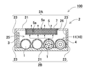
- FIG. 1 is a schematic horizontal sectional view showing an internal structure of a battery pack according to Embodiment 1 of the present invention.
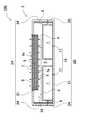
- 1 is a vertical cross-sectional view of a battery pack according to Embodiment 1 of the present invention.
- 1 is a vertical vertical sectional view of a battery pack according to Embodiment 1 of the present invention.
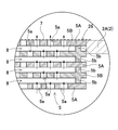
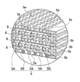
- 1 is a schematic perspective view showing an internal structure of a battery pack according to Embodiment 1 of the present invention. It is a partially expanded top view which shows the laminated state of a perforated plate. It is an expanded sectional view which shows the lamination state of a perforated plate. It is an expanded sectional perspective view which shows the laminated state of a perforated plate.
- FIG. 6 is a vertical cross-sectional view showing the internal structure of the battery pack according to Embodiment 2 of the present invention.
- a first aspect of the present invention is a battery pack that includes a battery cell having a discharge valve that opens when the internal pressure exceeds a set pressure, and a case that houses the battery cell.
- the case has an opening.
- the opening is closed with a resin perforated plate, the perforated plate has a plurality of through holes, the perforated plates are stacked to form an expansion gap of exhaust gas, and
- the through hole provided in the plate is arranged in a non-opposing position that does not face the through hole provided in the other adjacent porous plate, and the through hole formed in the porous plate and the expansion gap are passed through and discharged.
- the exhaust gas from the valve is exhausted to the outside of the case.
- the perforated plates formed by laminating each other have a quadrangular shape, and the perforated plates are laminated by inverting the two sides with the diagonal line of the quadrangular shape as an axis of symmetry and inverting the laminated porous plates.
- the holes are arranged in non-opposing positions.
- the perforated plate is square.
- the battery pack with this structure has a feature that it can be mass-produced while reducing the manufacturing cost because the through-holes can be arranged at non-opposing positions by stacking perforated plates having the same shape.
- the through hole of the perforated plate laminated inside the case is made larger than the through hole of the perforated plate laminated outside the case.
- the through hole of the inner perforated plate through which the exhaust gas injected from the exhaust valve first permeates is made larger than that of the outer perforated plate, so that the exhaust gas injected from the exhaust valve penetrates smoothly. It can be passed through the hole and quickly exhausted to the outside of the case.
- the perforated plate is integrally formed with the protruding portion, and the perforated plates are laminated to form an expansion gap.
- the expansion gaps having a predetermined gap can be easily and accurately provided by the protrusions in a state where a plurality of porous plates are stacked.
- the inner diameter of the through hole of the perforated plate is 0.5 mm or more and 3 mm or less.
- the case is a rectangular parallelepiped in which a peripheral wall is connected around a quadrangular surface plate, and the battery cell is in a posture parallel to the surface plate and has a valve-side end surface provided with a discharge valve. Is housed in a position facing the inside of the peripheral wall, and a perforated plate is provided on the surface plate.
- the ejection direction of the exhaust gas ejected from the battery cell and the direction of passage of the exhaust gas through the through hole of the perforated plate intersect with each other. The energy of the exhaust gas can be efficiently attenuated by discharging the exhaust gas while changing the direction in the case.
- the perforated plate is provided with through holes at intersections in a grid pattern.
- the battery pack having this structure it is possible to efficiently provide a large number of through holes in the perforated plate while efficiently disposing the through holes of the perforated plates that are laminated and face each other at the non-opposing positions.
- the case has a label attached to the surface of the perforated plate that is peeled or melted by the exhaust gas discharged from the discharge valve. Since the discharge side of the porous plate is closed by the label in this battery pack, it is possible to effectively prevent foreign matter from entering the case from the outside to the inside through the through hole of the porous plate.
- the battery cell is a non-aqueous electrolyte secondary battery. Furthermore, the eleventh invention of the present invention uses a lithium-ion battery as the battery cell.
- the battery pack 100 shown in FIGS. 1 to 4 includes a plurality of rechargeable battery cells 1, a circuit board 3 on which a protection circuit for the battery cells 1 and the like are mounted, and a case 2 accommodating the battery cells 1 and the circuit board 3. With.
- the battery cell 1 is a cylindrical battery.
- the cylindrical battery has an electrode and an electrolytic solution housed in a cylindrical metal case.
- the metal case has a closed structure in which a sealing plate is airtightly fixed to the opening of the outer can whose bottom is closed.
- the outer can is manufactured by pressing a metal plate.
- the sealing plate is airtightly fixed by caulking the periphery of the opening of the outer can via a packing made of an insulating material.
- the battery cell 1 is provided with a discharge valve on the sealing plate to prevent the metal case from being damaged due to abnormally high internal pressure.
- the discharge valve is provided with an opening in the sealing plate for discharging internal gas and the like in the opened state.
- the battery cell may be provided with a discharge valve and its opening at the bottom of the outer can.
- the discharge valve opens when the internal pressure becomes higher than a set pressure, for example, 1.5 MPa, and prevents the metal case from being broken due to the increase in the internal pressure.
- the discharge valve is opened in an abnormal state. Therefore, when the discharge valve is open, the temperature of the battery cell 1 is also very high. For this reason, the gas discharged from the discharge valve that opens and the electrolyte (spout) have an abnormally high temperature.
- a battery pack in which the battery cell 1 is a non-aqueous electrolyte secondary battery such as a lithium-ion battery has an abnormally high temperature of exhaust gas of 400° C. or higher.
- the lithium-ion battery is filled with a non-aqueous electrolyte solution, if it is discharged out of the case at a high temperature, it may come into contact with air and ignite, resulting in an abnormally high temperature.
- the exhaust gas ejected from the exhaust valve that opens opens at a high temperature, so it is safe to decay the energy of the exhaust gas and exhaust it outside the case. It is important to make it high.
- a plurality of battery cells 1 are arranged at fixed positions by a battery holder 4 and are arranged in a case as a battery block 10.
- the battery block 10 is composed of two sets of battery assemblies 11. In the battery assembly 11, the battery cell 1 is inserted into the battery holder 4 and the battery cell 1 is arranged at a fixed position.
- the battery holder 4 has the battery cells 1 arranged in four rows in parallel with the side wall 23 of the case 2.
- Two sets of battery assemblies 11 are arranged in two stages in the longitudinal direction of the case 2 to form a battery block 10 in which eight battery cells 1 are connected in series and in parallel in four rows and two stages.
- Each of the battery assemblies 11 is arranged in the case so that the openings of the discharge valves of the two battery cells 1 face the end wall 24 of the case 2.
- the battery assembly 11 is composed of four battery cells 1
- the battery block 10 is composed of two sets of battery assemblies 11, and the battery block 10 is arranged in the case.
- the battery pack of the present invention does not specify the number of battery cells housed in the case or the connection state.
- the circuit board 3 is mounted with electronic components (not shown) that are connected to the battery cells 1 and realize a protection circuit for the battery cells 1.
- the protection circuit is a circuit that prevents overcharge or overdischarge of the battery cell 1, a circuit that prevents overcurrent, or a circuit that cuts off current when the temperature rises abnormally.
- the circuit board 3 is arranged in a vertical posture inside the case 2, between the peripheral wall 22 and the battery block 10, and particularly at a position facing the side wall 23. doing.
- the circuit board 3 by disposing the circuit board 3 so as to face the side wall 23 that intersects with the end wall 24 that faces the discharge valve of the battery cell 1, the exhaust gas injected from the battery cell 1 can directly flow to the circuit.
- a gap for allowing exhaust gas to pass is provided between the porous plate 2 and the battery block 10 while preventing the exhaust gas from being injected onto the substrate 3, so that the exhaust gas injected from the exhaust valve can smoothly pass through the through hole of the porous plate 5. You can guide to 5a.
- the case 2 is made of a thermoplastic resin and is formed into a rectangular box shape as a whole, and the battery cell 1 and the circuit board 3 are incorporated therein.
- the case 2 in the figure includes an upper case 2A and a lower case 2B.
- the lower case 2B and the upper case 2A are provided with a peripheral wall 22 around a rectangular surface plate 21.
- the lower case 2B and the upper case 2A are connected by using the opening end surface of the peripheral wall 22 as a mating surface.
- the peripheral walls 22 of the lower case 2B and the upper case 2A include side walls 23 on both sides of the rectangular surface plate 21 extending in the longitudinal direction, and end walls 24 orthogonal to the side walls 23.
- the heat resistant cover 6 is arranged inside the end wall 24 facing the opening of the discharge valve.
- the heat-resistant cover 6 is a heat-resistant plate or sheet that withstands the temperature of exhaust gas.
- the heat-resistant cover 6 prevents the exhaust gas injected from the exhaust valve from being directly injected to the end wall 24, and scatters the exhaust gas in all directions. In the case where the end wall is formed of a heat resistant material, exhaust gas can be scattered around the end wall without providing a heat resistant cover.
- the surface plate 21 is provided with an opening 26, and the resin porous plate 5 having a large number of through holes 5a is arranged in the opening 26.
- the opening 26 is provided on almost the entire surface of the surface plate 21 of the upper case 2A.
- the opening 26 of the case 2 can be enlarged to smoothly discharge exhaust gas. Therefore, the opening area of the opening 26 is preferably 40% or more of the surface plate 21, and more preferably 50% or more. To do.
- a square opening 26 is provided in a square surface plate 21 to increase the opening area of the opening 26.
- the opening 26 is closed by the perforated plate 5 through which the exhaust gas can pass.
- the perforated plate 5 is joined and fixed to the surface plate 21 by a structure such as adhesion or welding, or is fixed by a fitting structure.
- the perforated plate 5 is fixed so that no gap is formed between it and the opening 26.
- a plurality of perforated plates 5 are laminated so that the energy of exhaust gas is attenuated and exhausted.
- An expansion gap 8 for exhaust gas is provided between the laminated porous plates 5.
- the through holes 5a of each of the laminated perforated plates 5 are arranged at non-opposing positions where the through holes 5a of the adjacent perforated plates 5 do not face each other, and the exhaust gas flows linearly through the plurality of perforated plates 5 and is not exhausted. It has a structure.
- the perforated plate 5 is formed of a thermoplastic resin into a plate shape and is provided with a large number of through holes 5a.
- the perforated plate 5 uses a heat-resistant plastic that can attenuate the energy of exhaust gas and discharge it to the outside.
- the perforated plate 5 is formed of a plastic having heat-resistant characteristics that does not thermally deform at the temperature of the exhaust gas, but the structure in which a plurality of perforated plates 5 are stacked with the expansion gaps 8 is not necessarily required.
- the porous plate 5 having a plurality of laminated layers is characterized in that it can be inexpensively mass-produced by injection molding with a thermoplastic resin such as polycarbonate.
- a thermoplastic resin such as polycarbonate.
- the present invention does not specify the plastic of the porous plate 5, and can be molded with a more excellent heat-resistant thermoplastic resin, for example, a thermoplastic resin such as a nylon resin or a fluororesin. It is also possible to mold with a plastic having more excellent heat resistance characteristics such as silicone resin or polyimide resin.
- the perforated plate 5 shown in the plan view of FIG. 5 circular through holes 5a are arranged at the intersections of the checkerboard lattice, and the vertical and horizontal pitches of the through holes 5a are constant.
- the through hole 5a can be made small to increase the permeation resistance of exhaust gas, but if it is too small, the exhaust gas cannot be smoothly discharged to the outside of the case, so the inner diameter is preferably 0.5 mm to 3 mm, more preferably 1 mm to 2 mm.
- the perforated plate 5 laminated on the innermost side of the case 2 allows the exhaust gas vigorously injected from the exhaust valve to permeate first.
- the perforated plate 5 has a through hole 5a larger than the other perforated plates 5 so that the exhaust gas injected from the exhaust valve can smoothly pass through the through hole 5a.
- the through holes 5a of all the perforated plates 5 may have the same size.
- the exhaust gas that has passed through the through holes 5a is jetted into the expansion gap 8 and adiabatically expanded.
- the temperature of the exhaust gas that adiabatically expands in the expansion gap 8 decreases.
- the expansion gap 8 is formed in a plurality of layers, the temperature is lowered due to adiabatic expansion every time the permeation hole 5a is passed through and the expansion gap 8 is flowed into the expansion gap 8.
- the thickness of the perforated plate 5 is preferably 1 mm to 3 mm because the perforated plate 5 can be formed thick and the through holes 5a can be lengthened to increase the permeation resistance of exhaust gas.
- the present invention does not specify the inner diameter of the through hole 5a and the thickness of the perforated plate 5 within the above-described range, but a large number of smaller through holes or a small number of larger through holes may be provided to further reduce the thickness of the perforated plate.
- the shape may be thickened so that the energy of the exhaust gas is attenuated and exhausted.
- the pitch of the through holes 5a is set such that the through holes 5a of the perforated plates 5 facing each other are arranged at the non-opposing positions, and a part of the through holes 5a is not arranged at the facing position of the perforated plates 5 to be laminated.
- the perforated plate 5 in which the through holes 5a are arranged in a checkerboard lattice is provided with four perforated plates 5 around the through holes 5a provided in one perforated plate 5.
- the through holes 5a are arranged at positions where they do not overlap.
- the structure in which the energy of exhaust gas is attenuated and can be safely discharged to the outside can be adopted as the structure in which the through holes 5a provided in the perforated plates 5 facing each other are partially overlapped. This is because most of the exhaust gas that has passed through the through holes 5a is laminated and collides with the surface of the porous plate 5 to attenuate the energy.
- the perforated plate 5 is integrally formed with a protrusion 5b on the surface thereof so as to form an expansion gap 8 having a constant gap by stacking.
- the protrusion 2b shown in the figure is a spacer rib integrally formed along the side edge of the perforated plate.
- the protruding height of the protruding portion 2b which is a spacer rib, specifies the dimension of the expansion gap 8.
- the expansion gap 8 is substantially equal to the thickness of the perforated plate 5, but the expansion gap 8 can be narrower or wider than the thickness of the perforated plate 5.
- the narrow expansion gap 8 increases the permeation resistance of exhaust gas to more effectively attenuate the energy of exhaust gas, but the exhaust gas cannot be exhausted smoothly.
- the expansion gap 8 is widened, a plurality of perforated plates 5 are laminated and become thicker. Therefore, the expansion gap 8 is set to a dimension such that exhaust gas can be smoothly exhausted while the entire laminated porous plate 5 is made as thin as possible, and further, harmful effects such as ignition can be prevented and safely exhausted, for example, 2 mm to 5 mm. To be done.
- the protrusions 2b are arranged scattered around the outer peripheral portion of the perforated plate 5, and further, if necessary, also arranged in the central portion so that the expansion gap 8 can be fixed and stacked.
- 6 and 7 show the perforated plate 5 laminated in five layers.
- the perforated plate 5 shown in these figures is formed by alternately laminating two types of perforated plates 5 including a flat perforated plate 5A and an intermediate perforated plate 5B.
- the planar porous plate 5A and the intermediate porous plate 5B are provided with through holes 5a at positions where they do not face each other, that is, at positions where they do not face each other.
- the intermediate porous plate 5B is provided by integrally forming the protruding portions 5b protruding on both sides.
- the perforated plate 5 of this shape can be laminated by alternately laminating two types of perforated plates 5, arranging the through holes 5a at non-opposing positions, and providing a constant expansion gap 8 between the perforated plates 5.
- the perforated plate 5 shown in FIGS. 6 and 7 has a laminated structure of five layers by laminating three flat perforated plates 5A and two intermediate perforated plates 5B.
- the planar porous plate 5A is laminated on both sides and in the middle, and the intermediate porous plate 5B is laminated between the planar porous plates 5A.
- the perforated plates 5 made of plastic, which are molded into two kinds of shapes are alternately laminated to form a laminated structure having an odd number of laminated layers.
- the through hole 5a provided in the innermost planar perforated plate 5A is made larger than the through holes 5a of the other perforated plates 5.
- the through hole 5a of the perforated plate 5 laminated on the innermost side of the case 2 is formed separately, only the perforated plate 5 laminated on the innermost side is separately molded. 5 can be laminated to form an odd number of layers of 3 or more.
- the perforated plate is formed into a shape in which each through hole can be arranged in a non-opposing position by alternately laminating the perforated plates formed in the same shape with the diagonal line as the axis of symmetry and inverting each other. be able to.
- This perforated plate has a square outer shape, for example, so that the through holes can be arranged at non-opposing positions while ideally stacking a plurality of perforated plates.
- the perforated plate is formed by arranging the perforated plates formed in the same shape by inverting the left and right centerlines with respect to the symmetry axis, or by inverting the upper and lower centerlines with respect to the symmetry axis.
- the perforations can be arranged in non-opposing positions by alternately inverting and stacking perforated plates having a rectangular outer shape.
- the perforated plate may be formed by rotating the perforated plates having the same shape by rotating 90° or 180° in a horizontal plane and stacking them so that the through holes can be arranged at non-opposing positions. it can.
- These perforated plates have the feature that they can be mass-produced while reducing the manufacturing cost because the through holes can be arranged in non-opposing positions when a plurality of laminated plates are laminated while using the same-shaped perforated plates. is there.
- the perforated plates that are vertically stacked and connected to each other may have positioning concave portions and positioning convex portions that are fitted to each other at opposite positions of the porous plates.
- the perforated plates to be laminated can be easily and surely connected to each other by fitting the positioning concave portion and the positioning convex portion.
- the through holes can be arranged in non-opposing positions. Can be reliably connected in the correct direction, and the respective through holes can be ideally arranged at non-opposing positions.
- the battery pack 100 has a diffusion space 25 inside the case 2.
- exhaust gas injected from an exhaust valve is injected into the diffusion space 25 to attenuate energy in the diffusion space 25, and then a through hole 5a provided in a further laminated porous plate 5 and a porous hole.
- Energy is attenuated by the expansion gap 8 provided between the plates 5 and discharged to the outside of the case.
- the through hole 5a is a permeation resistance through which the exhaust gas permeates, and the energy of the exhaust gas is attenuated.
- the expansion gap 8 causes the exhaust gas permeating through the through hole 5a to collide with the surface of the perforated plate 5 to reduce the energy of the exhaust gas. Decay.
- the ejection direction of the exhaust gas ejected from the battery cell 1 and the through hole 5a of the perforated plate 5 are arranged in a direction intersecting with each other. ing.
- the battery cell 1 is arranged so as to extend in the longitudinal direction of the rectangular surface plate 21, and the perforated plate 5 is arranged parallel to the surface plate 21 so as to close the opening 26 provided in the surface plate 21.
- the battery cell injects exhaust gas from the opening exhaust valve toward the surface of the front plate 21, and the through hole 5a permeates the exhaust gas in a direction orthogonal to the front plate 21 and exhausts it. That is, the ejection direction of the exhaust gas and the exhaust direction of the through hole 5a intersect each other, and are orthogonal to each other in the figure, and the exhaust gas is redirected in the case and exhausted to the outside.
- Exhaust gas injected from the exhaust valve into the case flows in the direction shown by the arrow in Fig. 4 and is exhausted outside the case.
- the discharge valve of the battery cell 1 has an opening facing the end wall 24 of the case 2.
- the exhaust gas injected from the exhaust valve is injected toward the end wall 24. Since the heat resistant cover 6 is arranged inside the end wall 24, the exhaust gas collides with the heat resistant cover 6 and is scattered around.
- the exhaust gas colliding with the heat resistant cover 6 flows into the diffusion space 25 and is diffused.
- the exhaust gas flowing into the diffusion space 25 collides with the inner surface of the case 2, is dispersed and redirected, and is exhausted to the outside from the through hole 5a, as shown by the arrow in the figure. As shown by the arrow in FIG.
- a label 7 that is peeled or melted by the exhaust gas discharged from the discharge valve is attached to the surface of the porous plate 5.
- the outer surface of the perforated plate 5 is closed with the label 7 to prevent foreign matter from entering the inside through the through holes 5a of the perforated plate 5.
- the label 7 is peeled off by the pressure of the exhaust gas passing through the through hole 5a of the porous plate 5, or by the heat of the high temperature exhaust gas. It is melted and removed.
- the battery pack 200 has openings 26 in the front surface plates 21 on both sides, and the openings 26 are closed by the porous plate 5.
- the through holes 5a of the perforated plate 5 can be made small and large in number to attenuate the energy of the exhaust gas to the outside. Can be exhausted.
- the present invention can be effectively used for a battery pack that safely exhausts exhaust gas.
Landscapes
- Chemical & Material Sciences (AREA)
- Electrochemistry (AREA)
- General Chemical & Material Sciences (AREA)
- Chemical Kinetics & Catalysis (AREA)
- Engineering & Computer Science (AREA)
- Manufacturing & Machinery (AREA)
- Computer Hardware Design (AREA)
- Life Sciences & Earth Sciences (AREA)
- Biophysics (AREA)
- Inorganic Chemistry (AREA)
- Gas Exhaust Devices For Batteries (AREA)
- Battery Mounting, Suspending (AREA)
- Secondary Cells (AREA)
Abstract
電池の排出弁から噴射される高温の排出ガスによる弊害を抑制して安全性を確保する。 パック電池は、内圧が設定圧力を越えると開弁する排出弁を有する電池セル(1)と、電池セル(1)を収納してなるケース(2)とを備えている。ケース(2)は、開口部(26)を有しており、この開口部(26)は、樹脂製の多孔板(5)で閉塞されている。多孔板(5)は複数の貫通穴(5a)を有し、多孔板(5)は複数枚を積層して排出ガスの膨張隙間を形成し、かつ、多孔板(5)に設けてなる貫通穴(5a)は、隣接する他の多孔板(5)に設けてなる貫通穴(5a)と対向しない非対向位置に配置して、多孔板(5)に設けてなる貫通穴(5a)と膨張隙間とを通過して排出弁の排出ガスをケースの外部に排出するようにしている。
Description
本発明は、外装ケースに充電できる電池を収納しているパック電池に関する。
携帯型電気機器の電源として使用されるパック電池は、近年高出力化が一層求められており、単位体積あたりの効率に優れたリチウムイオン電池等の非水系電解液二次電池が採用されている。リチウムイオン電池は、高出力である反面、何らかの原因によって内圧が上昇することがある。電池の内圧上昇に対する安全性を確保するために、設定圧力で開弁して破裂を防止する排出弁を設けている。排出弁が開弁するとき、電池は異常な発熱状態にあって排出弁からは高温のガスが勢いよく噴出される。排出弁から排出される排出ガスをケース外に排出するために、ケースに通気穴を設けて通気穴に金属製のメッシュ部材を設けているパック電池が開発されている。
特許文献1のパック電池は、外装ケースの通気穴に金属製のメッシュ部材を設けて、排出弁から噴射される排出ガスを速やかに外部に排出する。このパック電池は、電池セルから勢いよく噴射される高温の排出ガスを安全に外部に排出するのが難しい。とくに、非水系電解液二次電池であるリチウムイオン電池の排出弁から噴射される排出ガスは、400℃以上と異常に高温で、しかも勢いよく噴射されることから、メッシュ部材を通過して外部に排出されるガスがケース外で発煙し、あるいは発火する等の弊害を保障できない。
本発明は、このような本発明者らの知見に基づきなされたものである。本発明の主な目的は、電池の排出弁から噴射される高温の排出ガスによる弊害を抑制して安全性を確保するパック電池を提供することにある。
本発明のパック電池は、内圧が設定圧力を越えると開弁する排出弁を有する電池セル1と、電池セル1を収納してなるケース2とを備えている。ケース2は、開口部26を有しており、この開口部26は、樹脂製の多孔板5で閉塞されている。多孔板5は複数の貫通穴5aを有し、多孔板5は複数枚を積層して排出ガスの膨張隙間8を形成し、かつ、多孔板5に設けてなる貫通穴5aは、隣接する他の多孔板5に設けてなる貫通穴5aと対向しない非対向位置に配置して、多孔板5に設けてなる貫通穴5aと膨張隙間8とを通過して排出弁の排出ガスをケースの外部に排出するようにしている。
以上のパック電池は、電池セルの排出弁から噴射される高温の排出ガスによる弊害を抑制して安全性を高めることができる。それは、以上のパック電池が、ケースの開口部に、多数の貫通穴のあるプラスチック板の多孔板を設けており、さらに、多孔板は複数枚を膨張隙間を設けて積層して、積層された各々の多孔板の貫通穴を、対向しない非対向位置に配置して、排出ガスを多孔板の貫通穴に通過し、膨張隙間で断熱膨張させながら拡散し、さらに貫通穴を通過してケースの外部に排出するからである。以上の状態でケース外に排気される排出ガスは、電池セルから噴射された後、ケースの内部で多孔板に設けた複数の貫通穴に分散されて通過し、貫通穴を透過した後、膨張隙間に噴出されて断熱膨張して温度が低下し、さらに積層している排出側の多孔板表面に衝突し、分散してエネルギーを減衰し、さらに、多孔板の貫通穴を透過する状態でも、エネルギーを減衰してケースの外部に排気される。排出ガスは、複数の貫通穴を透過した後、膨張隙間で断熱膨張して温度を低下させながら、排出側の多孔板表面に衝突して方向転換し、分散される工程でもエネルギーが減衰され、さらに通過する経路が長くなって多数の貫通穴に分散して外部に排気されるので、ケース外に排出される状態で排出ガスがケース外に勢いよく排気されることがなく、発煙や発火等の弊害を抑制して安全性を高くできる。
本発明の第1の発明は、内圧が設定圧力を越えると開弁する排出弁を有する電池セルと、電池セルを収納してなるケースとを備えるパック電池であって、ケースは開口部を有し、開口部は、開口部は樹脂製の多孔板で閉塞され、多孔板は複数の貫通穴を有し、多孔板は複数枚を積層して排出ガスの膨張隙間を形成し、かつ、多孔板に設けてなる貫通穴は、隣接する他の多孔板に設けてなる貫通穴と対向しない非対向位置に配置しており、多孔板に設けてなる貫通穴と膨張隙間とを通過して排出弁の排出ガスをケースの外部に排出するようにしている。
本発明の第2の発明は、互いに積層してなる各々の多孔板を四角形状とし、多孔板は、四角形状の対角線を対称軸として表裏反転して積層して、積層された多孔板の貫通穴を非対向位置に配置している。さらに、本発明の第3の発明は、多孔板を正方形としている。この構造のパック電池は、同じ形状の多孔板を積層することで各々の貫通穴を非対向位置に配置できるので、製造コストを低減しながら多量生産できる特長がある。
本発明の第4の発明は、ケースの内側に積層してなる多孔板の貫通穴を、ケースの外側に積層してなる多孔板の貫通穴よりも大きくしている。この構造のパック電池は、排出弁から噴射された排出ガスが最初に透過する内側の多孔板の貫通穴を外側の多孔板よりも大きくするので、排出弁から噴射される排出ガスをスムーズに貫通穴に通過させて、速やかにケースの外部に排気できる。
本発明の第5の発明は、多孔板が突出部を一体的に成形して設けており、多孔板を積層状態とすることで膨張隙間を形成している。この構造のパック電池は、複数の多孔板を積層する状態で、この突出部により、所定の間隔の膨張隙間を簡単かつ正確に設けることができる。
本発明の第6の発明は、多孔板の貫通穴の内径を、0.5mm以上であって3mm以下としている。多孔板の貫通穴を以上の内径とする構造は、排出ガスの透過抵抗を大きくしながら、排出ガスをスムーズにケース外に排気できる。
本発明の第7の発明は、ケースが四角形の表面プレートの周囲に周壁を連結してなる直方体で、電池セルは、表面プレートと平行な姿勢であって、排出弁を設けてなる弁側端面を周壁の内側に対向する姿勢で収納し、多孔板を表面プレートに設けている。この構造のパック電池は、電池セルから噴射される排出ガスの噴出方向と、多孔板の貫通穴を排出ガスが通過する方向とを互いに交差する方向とするので、電池セルから噴射される排出ガスをケース内で方向変換しながら外部に排出して、排出ガスのエネルギーを効率よく減衰できる。
本発明の第8の発明は、多孔板が碁盤格子状の交点に貫通穴を設けている。この構造のパック電池は、多孔板に多数の貫通穴を効率よく設けながら、互いに積層されて対向する多孔板の貫通穴を効率よく非対向位置に配置できる。
本発明の第9の発明は、ケースが、多孔板の表面に、排出弁から排出される排出ガスで剥離され、あるいは溶融されるラベルを付着している。このパック電池は、多孔板の排出側をラベルで閉塞するので、ケースの外部から内部に多孔板の貫通穴を通過して異物が侵入するのを有効に防止できる。
本発明の第10の発明は、電池セルを非水系電解液二次電池としている。さらに、本発明の第11の発明は、電池セルをリチウムイオン電池としている。
以下、図面に基づいて本発明を詳細に説明する。なお、以下の説明では、必要に応じて特定の方向や位置を示す用語(例えば、「上」、「下」、及びそれらの用語を含む別の用語)を用いるが、それらの用語の使用は図面を参照した発明の理解を容易にするためであって、それらの用語の意味によって本発明の技術的範囲が制限されるものではない。また、複数の図面に表れる同一符号の部分は同一もしくは同等の部分又は部材を示す。
さらに以下に示す実施形態は、本発明の技術思想の具体例を示すものであって、本発明を以下に限定するものではない。また、以下に記載されている構成部品の寸法、材質、形状、その相対的配置等は、特定的な記載がない限り、本発明の範囲をそれのみに限定する趣旨ではなく、例示することを意図したものである。また、一の実施の形態、実施例において説明する内容は、他の実施の形態、実施例にも適用可能である。また、図面が示す部材の大きさや位置関係等は、説明を明確にするため、誇張していることがある。
さらに以下に示す実施形態は、本発明の技術思想の具体例を示すものであって、本発明を以下に限定するものではない。また、以下に記載されている構成部品の寸法、材質、形状、その相対的配置等は、特定的な記載がない限り、本発明の範囲をそれのみに限定する趣旨ではなく、例示することを意図したものである。また、一の実施の形態、実施例において説明する内容は、他の実施の形態、実施例にも適用可能である。また、図面が示す部材の大きさや位置関係等は、説明を明確にするため、誇張していることがある。
(実施形態1)
図1~図4に示すパック電池100は、充電できる複数の電池セル1と、電池セル1の保護回路等を実装する回路基板3と、電池セル1と回路基板3を収納しているケース2とを備える。
図1~図4に示すパック電池100は、充電できる複数の電池セル1と、電池セル1の保護回路等を実装する回路基板3と、電池セル1と回路基板3を収納しているケース2とを備える。
(電池セル1)
電池セル1は円筒形電池である。円筒形電池は、円筒状の金属ケースに電極と電解液を収納している。金属ケースは、底を閉塞している外装缶の開口部に、封口板を気密に固定している密閉構造としている。外装缶は、金属板をプレス加工して製作される。封口板は、絶縁材のパッキンを介して外装缶の開口部周縁にカシメ加工して気密に固定される。
電池セル1は円筒形電池である。円筒形電池は、円筒状の金属ケースに電極と電解液を収納している。金属ケースは、底を閉塞している外装缶の開口部に、封口板を気密に固定している密閉構造としている。外装缶は、金属板をプレス加工して製作される。封口板は、絶縁材のパッキンを介して外装缶の開口部周縁にカシメ加工して気密に固定される。
電池セル1は、図示しないが、金属ケースの内圧が異常に高くなって破損するのを防止するために、封口板に排出弁を設けている。排出弁は、開口する状態で内部のガスなどを排出する開口部を封口板に設けている。ただし、電池セルは、外装缶の底部に排出弁とその開口部を設けることもできる。排出弁は、内圧が設定圧力、たとえば1.5MPaよりも高くなると開弁して、内圧上昇による金属ケースの破壊を防止する。排出弁は、異常な状態で開弁される。したがって、排出弁が開弁する状態では、電池セル1の温度も非常に高くなっている。このため、開弁する排出弁から排出されるガスや電解液(噴出物)は異常な高温となっている。とくに、電池セル1をリチウムイオン電池等の非水系電解液二次電池とするパック電池は、排出ガスが400℃以上である異常な高温となる。さらに、リチウムイオン電池は、非水系の電解液を充填していることから、これが高温でケース外に排出されると、空気に触れて発火して、さらに異常な高温となることがある。リチウムイオン電池に限らず、他の充電できる電池においても、開弁する排出弁から噴出される排出ガスは高温となるので、排出ガスのエネルギーを減衰してケース外に排気することは安全性を高くすることから大切である。
図1~図4のパック電池100は、複数の電池セル1を電池ホルダー4で定位置に配置して電池ブロック10としてケース内に配置している。電池ブロック10は、2組の電池組立11からなる。電池組立11は、電池ホルダー4に電池セル1を挿入して電池セル1を定位置に配置している。電池ホルダー4は、ケース2の側部壁23と平行に4列に電池セル1を配置している。2組の電池組立11がケース2の長手方向に2段に配列されて、4列2段に8本の電池セル1を直列と並列に接続している電池ブロック10を構成している。各々の電池組立11は、2本の電池セル1の排出弁の開口部をケース2の端部壁24と対向してケース内に配置されている。図のパック電池100は、電池組立11を4個の電池セル1で構成して、2組の電池組立11で電池ブロック10を構成して、電池ブロック10をケース内に配置しているが、本発明のパック電池は、ケースに収納する電池セルの個数や接続状態を特定しない。
(回路基板3)
回路基板3は、電池セル1に接続されて電池セル1の保護回路を実現する電子部品(図示せず)を実装している。保護回路は、電池セル1の過充電や過放電を防止する回路、あるいは過電流を防止する回路、あるいは又温度が異常に上昇する状態で電流を遮断する回路である。図1と図2に示すパック電池100は、回路基板3を、ケース2の内部において、周壁22と電池ブロック10の間であって、とくに、側部壁23と対向する位置に垂直姿勢で配置している。このように、電池セル1の排出弁と対向する端部壁24と交差する側部壁23に対向して回路基板3を配置することで、電池セル1から噴射される排出ガスが直接に回路基板3に噴射されるのを防止しながら、多孔板2と電池ブロック10との間に排出ガスを通過させる隙間を設けて、排出弁から噴射される排出ガスをスムーズに多孔板5の貫通穴5aに案内できる。
回路基板3は、電池セル1に接続されて電池セル1の保護回路を実現する電子部品(図示せず)を実装している。保護回路は、電池セル1の過充電や過放電を防止する回路、あるいは過電流を防止する回路、あるいは又温度が異常に上昇する状態で電流を遮断する回路である。図1と図2に示すパック電池100は、回路基板3を、ケース2の内部において、周壁22と電池ブロック10の間であって、とくに、側部壁23と対向する位置に垂直姿勢で配置している。このように、電池セル1の排出弁と対向する端部壁24と交差する側部壁23に対向して回路基板3を配置することで、電池セル1から噴射される排出ガスが直接に回路基板3に噴射されるのを防止しながら、多孔板2と電池ブロック10との間に排出ガスを通過させる隙間を設けて、排出弁から噴射される排出ガスをスムーズに多孔板5の貫通穴5aに案内できる。
(ケース2)
ケース2は、熱可塑性樹脂で、全体を四角形の箱形に成形されて、内部には電池セル1と回路基板3とを内蔵している。図のケース2は、上ケース2Aと下ケース2Bとからなる。下ケース2Bと上ケース2Aは、長方形の表面プレート21の周囲に周壁22を設けている。下ケース2Bと上ケース2Aは、周壁22の開口端面を合わせ面として連結している。下ケース2Bと上ケース2Aの周壁22は、長方形の表面プレート21の長手方向に伸びる両側の側部壁23と、この側部壁23に直交する端部壁24とからなる。排出弁の開口部と対向する端部壁24は、内側に耐熱カバー6を配置している。耐熱カバー6は排出ガスの温度に耐える耐熱性のあるプレートやシートである。耐熱カバー6は、排出弁から噴射される排出ガスが直接に端部壁24に噴射されるのを阻止して、排出ガスを四方に飛散させる。耐熱性のある材料で端部壁を成形しているケースは、耐熱カバーを設けることなく、排出ガスを端部壁で周囲に飛散できる。
ケース2は、熱可塑性樹脂で、全体を四角形の箱形に成形されて、内部には電池セル1と回路基板3とを内蔵している。図のケース2は、上ケース2Aと下ケース2Bとからなる。下ケース2Bと上ケース2Aは、長方形の表面プレート21の周囲に周壁22を設けている。下ケース2Bと上ケース2Aは、周壁22の開口端面を合わせ面として連結している。下ケース2Bと上ケース2Aの周壁22は、長方形の表面プレート21の長手方向に伸びる両側の側部壁23と、この側部壁23に直交する端部壁24とからなる。排出弁の開口部と対向する端部壁24は、内側に耐熱カバー6を配置している。耐熱カバー6は排出ガスの温度に耐える耐熱性のあるプレートやシートである。耐熱カバー6は、排出弁から噴射される排出ガスが直接に端部壁24に噴射されるのを阻止して、排出ガスを四方に飛散させる。耐熱性のある材料で端部壁を成形しているケースは、耐熱カバーを設けることなく、排出ガスを端部壁で周囲に飛散できる。
ケース2は、表面プレート21に開口部26を設けて、この開口部26に、多数の貫通穴5aのある樹脂製の多孔板5を配置している。図1~図4のケース2は、上ケース2Aの表面プレート21のほぼ全面に開口部26を設けている。パック電池100は、ケース2の開口部26を大きくして、排出ガスをスムーズに排気できるので、開口部26の開口面積は、好ましくは表面プレート21の40%以上、さらに好ましくは50%以上とする。この図のケース2は、四角形の表面プレート21に四角形の開口部26を設けて、開口部26の開口面積を大きくしている。
(多孔板5)
開口部26は、排出ガスが通過できる多孔板5で塞いでいる。多孔板5は、表面プレート21に接着や溶着等の構造で接合して固定され、あるいは嵌合構造で固定される。多孔板5は、開口部26との間に隙間ができないように固定される。多孔板5は、排出ガスのエネルギーを減衰して排気するように、複数枚を積層している。積層された多孔板5の間には、排出ガスの膨張隙間8を設けている。積層された各々の多孔板5の貫通穴5aは、隣接する多孔板5の貫通穴5aを対向しない非対向位置に配置して、排出ガスが複数の多孔板5を直線的に流れて排気しない構造としている。多孔板5は、熱可塑性樹脂を板状に成形して、多数の貫通穴5aを設けている。
開口部26は、排出ガスが通過できる多孔板5で塞いでいる。多孔板5は、表面プレート21に接着や溶着等の構造で接合して固定され、あるいは嵌合構造で固定される。多孔板5は、開口部26との間に隙間ができないように固定される。多孔板5は、排出ガスのエネルギーを減衰して排気するように、複数枚を積層している。積層された多孔板5の間には、排出ガスの膨張隙間8を設けている。積層された各々の多孔板5の貫通穴5aは、隣接する多孔板5の貫通穴5aを対向しない非対向位置に配置して、排出ガスが複数の多孔板5を直線的に流れて排気しない構造としている。多孔板5は、熱可塑性樹脂を板状に成形して、多数の貫通穴5aを設けている。
多孔板5は、排出ガスのエネルギーを減衰して外部に排気できる耐熱特性のプラスチックを使用する。多孔板5は、排出ガスの温度で熱変形しない耐熱特性のプラスチックで成形することを理想とするが、複数の多孔板5を膨張隙間8を設けて積層する構造は、必ずしも全ての多孔板5が排出ガスで熱変形しない耐熱特性とする必要はない。内側の多孔板5が熱変形しても、外側の多孔板5が、残存する多数の貫通穴5aで排出ガスを減衰して排気できる状態に保時して、パック電池の安全は確保できるからである。複数枚を積層している多孔板5は、ポリカーボネート等の熱可塑性樹脂で射出成形して安価に多量生産できる特徴がある。ただし、本発明は、多孔板5のプラスチックを特定するものでなく、さらに優れた耐熱性の熱可塑性樹脂、たとえば、ナイロン樹脂やフッ素樹脂等の熱可塑性樹脂で成形することができ、さらにまた、シリコン樹脂やポリイミド樹脂等のより耐熱特性に優れたプラスチックで成形することもできる。
図5の平面図に示す多孔板5は、碁盤格子の交点に円形の貫通穴5aを配置して、貫通穴5aの縦横のピッチを一定としている。貫通穴5aは、小さくして排出ガスの透過抵抗を大きくできるが、小さすぎると排出ガスをスムーズにケース外に排気できないので、好ましくはその内径を0.5mm~3mm、さらに好ましくは、1mm~2mmとする。ケース2の最も内側に積層される多孔板5は、排出弁から勢いよく噴射された排出ガスが最初に透過する。この多孔板5は、貫通穴5aを他の多孔板5よりも大きくして、排出弁から噴射される排出ガスをスムーズに貫通穴5aに透過できる。ただし、全ての多孔板5の貫通穴5aを同じ大きさとすることもできる。貫通穴5aを透過した排出ガスは、膨張隙間8に噴出されて断熱膨張される。膨張隙間8で断熱膨張する排出ガスは温度が低下する。3枚以上の多孔板5を積層する構造は、複数層に膨張隙間8ができるので、貫通穴5aを透過して膨張隙間8に流入される毎に断熱膨張して温度が低下する。
多孔板5は、厚く成形して貫通穴5aを長くして排出ガスの透過抵抗を大きくできるので、多孔板5の厚さは、好ましくは1mm~3mmとする。ただ、本発明は貫通穴5aの内径と多孔板5の厚さを前述の範囲に特定するものでなく、より小さい貫通穴を多数設け、あるいはより大きい貫通穴を少数設け、さらに多孔板を薄くあるいは厚くして、排出ガスのエネルギーを減衰して排気する形状とすることもできる。貫通穴5aのピッチは、対向する多孔板5の貫通穴5aが非対向位置に配置されて、積層する多孔板5の対向位置に、貫通穴5aの一部も配置されない寸法に設定される。貫通穴5aを碁盤格子状に配置する多孔板5は、図5の平面図に示すように、ひとつの多孔板5に設けた貫通穴5aの周囲に、積層する多孔板5に設けた4個の貫通穴5aが重ならない位置に配置する。ただし、互いに対向して配置される多孔板5に設けた貫通穴5aの一部が重なる位置に配置する構造としても、排出ガスのエネルギーが減衰して安全に外部に排気できる構造は採用できる。それは、貫通穴5aを透過した排出ガスのほとんどが、積層して多孔板5の表面に衝突してエネルギーを減衰するからである。
多孔板5は、図6と図7に示すように、積層して一定の隙間の膨張隙間8ができるように、表面に突出部5bを一体的に成形して設けている。図に示す突出部2bは、多孔板の側縁部に沿って一体成形されたスペーサリブとしている。スペーサリブである突出部2bの突出高さは、膨張隙間8の寸法を特定する。図6に示す多孔板5は、膨張隙間8を多孔板5の厚さにほぼ等しくしているが、膨張隙間8は、多孔板5の厚さよりも狭く、あるいは広くすることもできる。狭い膨張隙間8は、排出ガスの透過抵抗を大きくして、排出ガスのエネルギーをより効果的に減衰できるが、排出ガスをスムーズに排気できなくなる。膨張隙間8を広くすると、複数の多孔板5を積層して厚くなる。したがって、膨張隙間8は、積層した多孔板5全体をできる限り薄くしながら、排出ガスをスムーズに排気でき、さらに発火などの弊害を防止して安全に排気できる寸法、たとえば、2mm~5mmに設定される。
突出部2bは、多孔板5の外周部に点在して配置され、さらに必要であれば中央部にも配置して、膨張隙間8を一定にして積層できる。図6及び図7は、5層に積層している多孔板5を示している。これらの図に示す多孔板5は、平面多孔板5Aと中間多孔板5Bとからなる2種の多孔板5を交互に積層している。平面多孔板5Aと中間多孔板5Bは、対向しない位置、すなわち非対向位置に貫通穴5aを設けている。中間多孔板5Bは、両面に突出する突出部5bを一体的に成形して設けている。この形状の多孔板5は、2種の多孔板5を交互に積層して、貫通穴5aを非対向位置に配置し、かつ多孔板5の間に一定の膨張隙間8を設けて積層できる。図6と図7に示す多孔板5は、3枚の平面多孔板5Aと、2枚の中間多孔板5Bを積層して5層の積層構造としている。平面多孔板5Aは、両面と中間に積層され、中間多孔板5Bは、平面多孔板5Aの間に積層されている。この構造は、2種の形状に成形しているプラスチック製の多孔板5を、交互に積層して積層枚数を奇数枚の積層構造にできる。図6と図7に示す多孔板5は、最も内側に配置される平面多孔板5Aに設けた貫通穴5aを他の多孔板5の貫通穴5aよりも大きくしている。このように、ケース2の最も内側に積層する多孔板5の貫通穴5aを大きくするパック電池100は、最も内側に積層する多孔板5のみ別に成形するので、3種の形状に成形した多孔板5を積層して、3層以上の奇数層に積層できる。
さらに、多孔板は、図示しないが、同一形状に成形された多孔板を対角線を対称軸として表裏反転して交互に積層することで、各々の貫通穴を非対向位置に配置できる形状に成形することができる。この多孔板は、例えば、外形を正方形状とすることで、複数の多孔板を理想的に積層しながら各々の貫通穴を非対向位置に配置できる。また、多孔板は、同一形状に成形された多孔板を、左右の中心線を対称軸として表裏反転して積層し、あるいは上下の中心線を対称軸として表裏反転して積層する状態で各々の貫通穴を非対向位置に配置できるように成形することもできる。この構造は、例えば、外形を長方形とする多孔板を交互に反転しながら積層することで、各々の貫通穴を非対向位置に配置できる。さらにまた、多孔板は、同一形状に成形された多孔板を、水平面内で90度又は180度回転させて積層することで、各々の貫通穴を非対向位置に配置できるように成形することもできる。これらの多孔板は、同じ形状の多孔板を使用しながら、複数の積層板を積層する状態では、各々の貫通穴を非対向位置に配置できるので、製造コストを低減しながら多量生産できる特長がある。
さらに、上下に積層されて互いに連結される多孔板は、図示しないが、多孔板の対向する位置に、互いに嵌合する位置決め凹部と位置決め凸部を設けることができる。この構造は、位置決め凹部と位置決め凸部を嵌合させることで、積層される多孔板を、簡単かつ確実に位置決めしながら連結できる。とくに、上下の多孔板を特定の向きに積層することで、各々の貫通穴を非対向位置に配置できる多孔板は、位置決め凹部と位置決め凸部を嵌合させることで、積層される多孔板同士を、正しい向きに確実に連結させて、それぞれの貫通穴を理想的に非対向位置に配置できる。
パック電池100は、ケース2の内部に拡散スペース25を設けている。このパック電池100は、排出弁から噴射される排出ガスを拡散スペース25に噴射して、拡散スペース25でエネルギーを減衰させた後、さらに積層された多孔板5に設けた貫通穴5aと、多孔板5の間に設けた膨張隙間8とでエネルギーを減衰してケース外に排出する。貫通穴5aは、排出ガスが透過する透過抵抗で、排出ガスのエネルギーを減衰し、膨張隙間8は貫通穴5aを透過した排出ガスを多孔板5の表面に衝突させて、排出ガスのエネルギーを減衰する。
図4の概略斜視図に示すパック電池100は、電池セル1から噴射される排出ガスの噴出方向と、多孔板5の貫通穴5aを排出ガスが透過する方向とが互いに交差する方向に配置している。電池セル1は、長方形の表面プレート21の長手方向に伸びる姿勢で配置され、多孔板5は、表面プレート21に設けた開口部26を塞ぐように、表面プレート21と平行に配置される。電池セルは、開弁する排出弁から表面プレート21の表面方向に排出ガスを噴射し、貫通穴5aは、排出ガスを表面プレート21に直交する方向に透過して排気する。すなわち、排出ガスの噴射方向と、貫通穴5aの排気方向は互いに交差する姿勢となり、図にあっては直交する方向となり、排出ガスは、ケース内で方向変更して外部に排気される。
排出弁からケース内に噴射された排出ガスは、図4の矢印で示す方向に流動してケース外に排気される。電池セル1の排出弁は、開口部をケース2の端部壁24に対向して配置している。排出弁から噴射される排出ガスは、端部壁24に向かって噴射される。端部壁24の内側には耐熱カバー6を配置しているので、排出ガスは耐熱カバー6に衝突して周囲に飛散される。耐熱カバー6に衝突した排出ガスは、拡散スペース25に流入して拡散される。拡散スペース25に流入する排出ガスは、図の矢印で示すように、ケース2の内面に衝突し、分散され、方向転換されて貫通穴5aから外部に排気される。図4の矢印で示すように、ケース2の内面に衝突し、分散し、方向転換してエネルギーを減衰して貫通穴5aを透過し、さらに貫通穴5aと膨張隙間8とでエネルギーを減衰してケース外に排気される。エネルギーを減衰してケース外に排気する構造は、ケース外での発火等の弊害を抑制して安全性を向上できる。
さらに、図2と図3に示すケース2は、多孔板5の表面に、排出弁から排出される排出ガスで剥離され、あるいは溶融されるラベル7を付着している。このパック電池100は、多孔板5の外側表面をラベル7で閉塞することで、多孔板5の貫通穴5aを通過して内部に異物が侵入するのを防止できる。また、このラベル7は、電池セル1の排出弁から排出ガスが排出される際には、多孔板5の貫通穴5aを通過する排出ガスの圧力により剥離され、あるいは高温の排出ガスの熱により溶融されて除去される。
(実施形態2)
このパック電池200は、図8の断面図に示すように、両面の表面プレート21に開口部26を設けて、開口部26を多孔板5で塞いでいる。このパック電池200は、開口部26の開口面積を広くして多孔板5を大きくできるので、多孔板5の貫通穴5aを小さく、数を多くして、排出ガスのエネルギーを減衰して外部に排気できる。
このパック電池200は、図8の断面図に示すように、両面の表面プレート21に開口部26を設けて、開口部26を多孔板5で塞いでいる。このパック電池200は、開口部26の開口面積を広くして多孔板5を大きくできるので、多孔板5の貫通穴5aを小さく、数を多くして、排出ガスのエネルギーを減衰して外部に排気できる。
本発明は排出ガスを安全に排気するパック電池に有効に使用できる。
100、200…パック電池
1…電池セル
2…ケース
2A…上ケース
2B…下ケース
3…回路基板
4…電池ホルダー
5…多孔板
5A…平面多孔板
5B…中間多孔板
5a…貫通穴
5b…突出部
6…耐熱カバー
7…ラベル
8…膨張隙間
10…電池ブロック
11…電池組立
21…表面プレート
22…周壁
23…側部壁
24…端部壁
25…拡散スペース
26…開口部
1…電池セル
2…ケース
2A…上ケース
2B…下ケース
3…回路基板
4…電池ホルダー
5…多孔板
5A…平面多孔板
5B…中間多孔板
5a…貫通穴
5b…突出部
6…耐熱カバー
7…ラベル
8…膨張隙間
10…電池ブロック
11…電池組立
21…表面プレート
22…周壁
23…側部壁
24…端部壁
25…拡散スペース
26…開口部
Claims (11)
- 内圧が設定圧力を越えると開弁する排出弁を有する電池セルと、
前記電池セルを収納してなるケースとを備えるパック電池であって、
前記ケースは開口部を有し、
前記開口部は樹脂製の多孔板で閉塞され、
前記多孔板は複数の貫通穴を有し、
前記多孔板は複数枚を積層して排出ガスの膨張隙間を形成し、かつ、
前記多孔板に設けてなる前記貫通穴は、隣接する他の多孔板に設けてなる貫通穴と対向しない非対向位置に配置されており、
前記多孔板に設けてなる前記貫通穴と前記膨張隙間とを通過して前記排出弁の排出ガスをケースの外部に排出するようにしてなることを特徴とするパック電池。 - 請求項1に記載するパック電池であって、
互いに積層してなる各々の前記多孔板は四角形状であり、
前記多孔板は、四角形状の対角線を対称軸として表裏反転して積層されて、積層された前記多孔板の貫通穴が非対向位置に配置してなることを特徴とするパック電池。 - 請求項2に記載するパック電池であって、
前記多孔板は正方形であることを特徴とするパック電池。 - 請求項1に記載するパック電池であって、
前記ケースの内側に積層してなる前記多孔板の貫通穴が、前記ケースの外側に積層してなる前記多孔板の貫通穴よりも大きいことを特徴とするパック電池。 - 請求項1ないし4のいずれかに記載するパック電池であって、
前記多孔板は突出部を一体的に成形して設けており、前記多孔板を積層状態とすることで前記膨張隙間を形成してなることを特徴とするパック電池。 - 請求項1ないし5のいずれかに記載するパック電池であって、
前記多孔板の前記貫通穴の内径が、0.5mm以上であって3mm以下であることを特徴とするパック電池。 - 請求項1ないし6のいずれかに記載するパック電池であって、
前記ケースが四角形の表面プレートの周囲に周壁を連結してなる直方体で、
前記電池セルは、前記表面プレートと平行な姿勢であって、前記排出弁を設けてなる弁側端面を前記周壁の内側に対向する姿勢で収納され、
前記多孔板が表面プレートに設けられてなることを特徴とするパック電池。 - 請求項1ないし7のいずれかに記載するパック電池であって、
前記多孔板が碁盤格子状の交点に前記貫通穴を設けてなることを特徴とするパック電池。 - 請求項1ないし8のいずれかに記載するパック電池であって、
前記ケースが、前記多孔板の表面に、前記排出弁から排出される排出ガスで剥離され、あるいは溶融されるラベルを付着してなることを特徴とするパック電池。 - 請求項1ないし9に記載するパック電池であって、
前記電池セルが非水系電解液二次電池であることを特徴とするパック電池。 - 請求項10に記載するパック電池であって、
前記電池セルがリチウムイオン電池であることを特徴とするパック電池。
Priority Applications (4)
| Application Number | Priority Date | Filing Date | Title |
|---|---|---|---|
| CN201980088999.0A CN113330621A (zh) | 2019-01-25 | 2019-12-09 | 电池组 |
| EP19911251.7A EP3916876B1 (en) | 2019-01-25 | 2019-12-09 | Battery pack |
| JP2020567405A JP7292812B2 (ja) | 2019-01-25 | 2019-12-09 | パック電池 |
| US17/422,817 US11984613B2 (en) | 2019-01-25 | 2019-12-09 | Battery pack |
Applications Claiming Priority (2)
| Application Number | Priority Date | Filing Date | Title |
|---|---|---|---|
| JP2019011547 | 2019-01-25 | ||
| JP2019-011547 | 2019-01-25 |
Publications (1)
| Publication Number | Publication Date |
|---|---|
| WO2020153017A1 true WO2020153017A1 (ja) | 2020-07-30 |
Family
ID=71736728
Family Applications (1)
| Application Number | Title | Priority Date | Filing Date |
|---|---|---|---|
| PCT/JP2019/048016 Ceased WO2020153017A1 (ja) | 2019-01-25 | 2019-12-09 | パック電池 |
Country Status (5)
| Country | Link |
|---|---|
| US (1) | US11984613B2 (ja) |
| EP (1) | EP3916876B1 (ja) |
| JP (1) | JP7292812B2 (ja) |
| CN (1) | CN113330621A (ja) |
| WO (1) | WO2020153017A1 (ja) |
Cited By (11)
| Publication number | Priority date | Publication date | Assignee | Title |
|---|---|---|---|---|
| WO2022024713A1 (ja) * | 2020-07-31 | 2022-02-03 | パナソニックIpマネジメント株式会社 | 電池ケース、及び電池パック |
| JPWO2022024894A1 (ja) * | 2020-07-31 | 2022-02-03 | ||
| DE102021112082A1 (de) | 2021-05-10 | 2022-11-10 | Bayerische Motoren Werke Aktiengesellschaft | Entgasungsvorrichtung sowie Traktionsbatterie und Kraftfahrzeug mit einer solchen |
| WO2022250311A1 (ko) * | 2021-05-26 | 2022-12-01 | 주식회사 엘지에너지솔루션 | 벤팅 가스의 온도 저감 및 스파크의 외부 배출 차단 구조를 적용한 배터리 팩 |
| WO2023072575A1 (de) * | 2021-10-25 | 2023-05-04 | Audi Ag | Gasabführkammer und batterieanordnung zum abführen von gasen aus einer kraftfahrzeugbatterie |
| KR20230170218A (ko) * | 2022-06-10 | 2023-12-19 | 신흥에스이씨주식회사 | 배터리 모듈 |
| JP2024520101A (ja) * | 2021-07-07 | 2024-05-21 | エルジー エナジー ソリューション リミテッド | 電池モジュール及び当該電池モジュールを含む電池パック |
| JP2024527746A (ja) * | 2022-06-21 | 2024-07-26 | エルジー エナジー ソリューション リミテッド | バッテリーモジュールフレーム |
| WO2024224904A1 (ja) | 2023-04-28 | 2024-10-31 | パナソニックIpマネジメント株式会社 | 電源装置 |
| WO2024253014A1 (ja) * | 2023-06-07 | 2024-12-12 | 株式会社Aescジャパン | 電池モジュール |
| WO2026053983A1 (ja) * | 2024-09-04 | 2026-03-12 | 株式会社Aescジャパン | 電池モジュール |
Families Citing this family (5)
| Publication number | Priority date | Publication date | Assignee | Title |
|---|---|---|---|---|
| US11984613B2 (en) * | 2019-01-25 | 2024-05-14 | Panasonic Energy Co., Ltd. | Battery pack |
| US12183942B2 (en) * | 2019-08-01 | 2024-12-31 | Panasonic Energy Co., Ltd. | Battery pack |
| CN115000583B (zh) * | 2022-08-04 | 2022-11-11 | 嘉兴模度新能源有限公司 | 热排放结构、电池单元、电池组、集装箱及电池组的制备方法 |
| US20240332719A1 (en) * | 2023-03-29 | 2024-10-03 | Snap-On Incorporated | Power tool battery with vents |
| WO2026036257A1 (zh) * | 2024-08-12 | 2026-02-19 | 宁德时代新能源科技股份有限公司 | 电池装置及用电装置 |
Citations (5)
| Publication number | Priority date | Publication date | Assignee | Title |
|---|---|---|---|---|
| JP2009212081A (ja) | 2008-02-04 | 2009-09-17 | Panasonic Corp | 電池パック、それを備えた電子機器および電池収納部を備えた電子機器 |
| JP2010061989A (ja) * | 2008-09-03 | 2010-03-18 | Toyota Motor Corp | 蓄電装置 |
| JP2015056323A (ja) * | 2013-09-12 | 2015-03-23 | 株式会社リチウムエナジージャパン | 蓄電装置 |
| WO2016136193A1 (ja) * | 2015-02-25 | 2016-09-01 | パナソニックIpマネジメント株式会社 | 電池モジュール |
| WO2017073201A1 (ja) * | 2015-10-28 | 2017-05-04 | ソニー株式会社 | 電子機器ケース、及びこれを備えた電池パック |
Family Cites Families (12)
| Publication number | Priority date | Publication date | Assignee | Title |
|---|---|---|---|---|
| JP2000284080A (ja) * | 1999-03-31 | 2000-10-13 | Nuclear Fuel Ind Ltd | 沸騰水型原子炉用燃料集合体 |
| JP2009183359A (ja) | 2008-02-04 | 2009-08-20 | Tomoyuki Kon | 積層緩衝材 |
| KR101010594B1 (ko) * | 2008-12-18 | 2011-01-24 | (주) 대아테크 | 자동차 에어백 장치의 인플레이터용 필터 |
| KR101156539B1 (ko) * | 2010-07-15 | 2012-06-20 | 삼성에스디아이 주식회사 | 배터리 팩 |
| JP6109926B2 (ja) * | 2013-03-29 | 2017-04-05 | 三洋電機株式会社 | 電池パック |
| CN105531846B (zh) | 2013-10-31 | 2019-04-05 | 松下知识产权经营株式会社 | 电池模块 |
| JP2016035817A (ja) | 2014-08-01 | 2016-03-17 | 三菱重工業株式会社 | モジュールカバー上部構造体、電池モジュール及び電池モジュールの熱暴走防止方法 |
| JP2016061989A (ja) * | 2014-09-19 | 2016-04-25 | 京セラドキュメントソリューションズ株式会社 | 画像形成装置 |
| CN106716675B (zh) * | 2014-10-17 | 2020-02-28 | 三洋电机株式会社 | 电池组 |
| WO2020153018A1 (ja) * | 2019-01-25 | 2020-07-30 | 三洋電機株式会社 | パック電池 |
| CN113302774B (zh) * | 2019-01-25 | 2024-03-29 | 松下新能源株式会社 | 电池组 |
| US11984613B2 (en) * | 2019-01-25 | 2024-05-14 | Panasonic Energy Co., Ltd. | Battery pack |
-
2019
- 2019-12-09 US US17/422,817 patent/US11984613B2/en active Active
- 2019-12-09 EP EP19911251.7A patent/EP3916876B1/en active Active
- 2019-12-09 WO PCT/JP2019/048016 patent/WO2020153017A1/ja not_active Ceased
- 2019-12-09 JP JP2020567405A patent/JP7292812B2/ja active Active
- 2019-12-09 CN CN201980088999.0A patent/CN113330621A/zh active Pending
Patent Citations (5)
| Publication number | Priority date | Publication date | Assignee | Title |
|---|---|---|---|---|
| JP2009212081A (ja) | 2008-02-04 | 2009-09-17 | Panasonic Corp | 電池パック、それを備えた電子機器および電池収納部を備えた電子機器 |
| JP2010061989A (ja) * | 2008-09-03 | 2010-03-18 | Toyota Motor Corp | 蓄電装置 |
| JP2015056323A (ja) * | 2013-09-12 | 2015-03-23 | 株式会社リチウムエナジージャパン | 蓄電装置 |
| WO2016136193A1 (ja) * | 2015-02-25 | 2016-09-01 | パナソニックIpマネジメント株式会社 | 電池モジュール |
| WO2017073201A1 (ja) * | 2015-10-28 | 2017-05-04 | ソニー株式会社 | 電子機器ケース、及びこれを備えた電池パック |
Cited By (20)
| Publication number | Priority date | Publication date | Assignee | Title |
|---|---|---|---|---|
| JPWO2022024894A1 (ja) * | 2020-07-31 | 2022-02-03 | ||
| JPWO2022024713A1 (ja) * | 2020-07-31 | 2022-02-03 | ||
| WO2022024713A1 (ja) * | 2020-07-31 | 2022-02-03 | パナソニックIpマネジメント株式会社 | 電池ケース、及び電池パック |
| JP7777779B2 (ja) | 2020-07-31 | 2025-12-01 | パナソニックIpマネジメント株式会社 | 電池パック、及び電池ケース |
| JP7731078B2 (ja) | 2020-07-31 | 2025-08-29 | パナソニックIpマネジメント株式会社 | 電池ケース、及び電池パック |
| DE102021112082A1 (de) | 2021-05-10 | 2022-11-10 | Bayerische Motoren Werke Aktiengesellschaft | Entgasungsvorrichtung sowie Traktionsbatterie und Kraftfahrzeug mit einer solchen |
| WO2022250311A1 (ko) * | 2021-05-26 | 2022-12-01 | 주식회사 엘지에너지솔루션 | 벤팅 가스의 온도 저감 및 스파크의 외부 배출 차단 구조를 적용한 배터리 팩 |
| JP7659086B2 (ja) | 2021-07-07 | 2025-04-08 | エルジー エナジー ソリューション リミテッド | 電池モジュール及び当該電池モジュールを含む電池パック |
| JP2024520101A (ja) * | 2021-07-07 | 2024-05-21 | エルジー エナジー ソリューション リミテッド | 電池モジュール及び当該電池モジュールを含む電池パック |
| US12431584B2 (en) | 2021-07-07 | 2025-09-30 | Lg Energy Solution, Ltd. | Battery module and battery pack including the same |
| JP2025092597A (ja) * | 2021-07-07 | 2025-06-19 | エルジー エナジー ソリューション リミテッド | 電池モジュール及び当該電池モジュールを含む電池パック |
| WO2023072575A1 (de) * | 2021-10-25 | 2023-05-04 | Audi Ag | Gasabführkammer und batterieanordnung zum abführen von gasen aus einer kraftfahrzeugbatterie |
| KR102835253B1 (ko) * | 2022-06-10 | 2025-07-17 | 범한유니솔루션 주식회사 | 배터리 모듈 |
| KR20230170218A (ko) * | 2022-06-10 | 2023-12-19 | 신흥에스이씨주식회사 | 배터리 모듈 |
| JP7673316B2 (ja) | 2022-06-21 | 2025-05-08 | エルジー エナジー ソリューション リミテッド | バッテリーモジュールフレーム |
| JP2024527746A (ja) * | 2022-06-21 | 2024-07-26 | エルジー エナジー ソリューション リミテッド | バッテリーモジュールフレーム |
| WO2024224904A1 (ja) | 2023-04-28 | 2024-10-31 | パナソニックIpマネジメント株式会社 | 電源装置 |
| EP4704237A1 (en) | 2023-04-28 | 2026-03-04 | Panasonic Intellectual Property Management Co., Ltd. | Power supply equipment |
| WO2024253014A1 (ja) * | 2023-06-07 | 2024-12-12 | 株式会社Aescジャパン | 電池モジュール |
| WO2026053983A1 (ja) * | 2024-09-04 | 2026-03-12 | 株式会社Aescジャパン | 電池モジュール |
Also Published As
| Publication number | Publication date |
|---|---|
| JPWO2020153017A1 (ja) | 2021-12-02 |
| EP3916876A1 (en) | 2021-12-01 |
| EP3916876A4 (en) | 2022-03-23 |
| CN113330621A (zh) | 2021-08-31 |
| JP7292812B2 (ja) | 2023-06-19 |
| EP3916876B1 (en) | 2024-05-15 |
| US20220069409A1 (en) | 2022-03-03 |
| US11984613B2 (en) | 2024-05-14 |
Similar Documents
| Publication | Publication Date | Title |
|---|---|---|
| JP7292812B2 (ja) | パック電池 | |
| JP7401467B2 (ja) | パック電池 | |
| JP7404275B2 (ja) | パック電池 | |
| JP7489330B2 (ja) | パック電池 | |
| JP7488771B2 (ja) | パック電池 | |
| JP6256846B2 (ja) | 電池モジュール | |
| JPWO2017130259A1 (ja) | 電池パック | |
| JP7520842B2 (ja) | パック電池 | |
| JP7609777B2 (ja) | パック電池 | |
| WO2025167315A1 (zh) | 电池单体、电池及用电装置 |
Legal Events
| Date | Code | Title | Description |
|---|---|---|---|
| 121 | Ep: the epo has been informed by wipo that ep was designated in this application |
Ref document number: 19911251 Country of ref document: EP Kind code of ref document: A1 |
|
| ENP | Entry into the national phase |
Ref document number: 2020567405 Country of ref document: JP Kind code of ref document: A |
|
| NENP | Non-entry into the national phase |
Ref country code: DE |
|
| ENP | Entry into the national phase |
Ref document number: 2019911251 Country of ref document: EP Effective date: 20210825 |