WO2020152934A1 - 積層ワーク成形装置 - Google Patents
積層ワーク成形装置 Download PDFInfo
- Publication number
- WO2020152934A1 WO2020152934A1 PCT/JP2019/043122 JP2019043122W WO2020152934A1 WO 2020152934 A1 WO2020152934 A1 WO 2020152934A1 JP 2019043122 W JP2019043122 W JP 2019043122W WO 2020152934 A1 WO2020152934 A1 WO 2020152934A1
- Authority
- WO
- WIPO (PCT)
- Prior art keywords
- mold
- sheet material
- work
- suction
- hole
- Prior art date
- Legal status (The legal status is an assumption and is not a legal conclusion. Google has not performed a legal analysis and makes no representation as to the accuracy of the status listed.)
- Ceased
Links
Images





Classifications
-
- B—PERFORMING OPERATIONS; TRANSPORTING
- B29—WORKING OF PLASTICS; WORKING OF SUBSTANCES IN A PLASTIC STATE IN GENERAL
- B29C—SHAPING OR JOINING OF PLASTICS; SHAPING OF MATERIAL IN A PLASTIC STATE, NOT OTHERWISE PROVIDED FOR; AFTER-TREATMENT OF THE SHAPED PRODUCTS, e.g. REPAIRING
- B29C43/00—Compression moulding, i.e. applying external pressure to flow the moulding material; Apparatus therefor
- B29C43/32—Component parts, details or accessories; Auxiliary operations
- B29C43/36—Moulds for making articles of definite length, i.e. discrete articles
-
- B—PERFORMING OPERATIONS; TRANSPORTING
- B29—WORKING OF PLASTICS; WORKING OF SUBSTANCES IN A PLASTIC STATE IN GENERAL
- B29C—SHAPING OR JOINING OF PLASTICS; SHAPING OF MATERIAL IN A PLASTIC STATE, NOT OTHERWISE PROVIDED FOR; AFTER-TREATMENT OF THE SHAPED PRODUCTS, e.g. REPAIRING
- B29C33/00—Moulds or cores; Details thereof or accessories therefor
- B29C33/12—Moulds or cores; Details thereof or accessories therefor with incorporated means for positioning inserts, e.g. labels
- B29C33/14—Moulds or cores; Details thereof or accessories therefor with incorporated means for positioning inserts, e.g. labels against the mould wall
- B29C33/18—Moulds or cores; Details thereof or accessories therefor with incorporated means for positioning inserts, e.g. labels against the mould wall using vacuum
-
- B—PERFORMING OPERATIONS; TRANSPORTING
- B21—MECHANICAL METAL-WORKING WITHOUT ESSENTIALLY REMOVING MATERIAL; PUNCHING METAL
- B21D—WORKING OR PROCESSING OF SHEET METAL OR METAL TUBES, RODS OR PROFILES WITHOUT ESSENTIALLY REMOVING MATERIAL; PUNCHING METAL
- B21D26/00—Shaping without cutting otherwise than using rigid devices or tools or yieldable or resilient pads, i.e. applying fluid pressure or magnetic forces
- B21D26/02—Shaping without cutting otherwise than using rigid devices or tools or yieldable or resilient pads, i.e. applying fluid pressure or magnetic forces by applying fluid pressure
- B21D26/021—Deforming sheet bodies
-
- B—PERFORMING OPERATIONS; TRANSPORTING
- B29—WORKING OF PLASTICS; WORKING OF SUBSTANCES IN A PLASTIC STATE IN GENERAL
- B29C—SHAPING OR JOINING OF PLASTICS; SHAPING OF MATERIAL IN A PLASTIC STATE, NOT OTHERWISE PROVIDED FOR; AFTER-TREATMENT OF THE SHAPED PRODUCTS, e.g. REPAIRING
- B29C33/00—Moulds or cores; Details thereof or accessories therefor
- B29C33/42—Moulds or cores; Details thereof or accessories therefor characterised by the shape of the moulding surface, e.g. ribs or grooves
-
- B—PERFORMING OPERATIONS; TRANSPORTING
- B29—WORKING OF PLASTICS; WORKING OF SUBSTANCES IN A PLASTIC STATE IN GENERAL
- B29C—SHAPING OR JOINING OF PLASTICS; SHAPING OF MATERIAL IN A PLASTIC STATE, NOT OTHERWISE PROVIDED FOR; AFTER-TREATMENT OF THE SHAPED PRODUCTS, e.g. REPAIRING
- B29C43/00—Compression moulding, i.e. applying external pressure to flow the moulding material; Apparatus therefor
- B29C43/02—Compression moulding, i.e. applying external pressure to flow the moulding material; Apparatus therefor of articles of definite length, i.e. discrete articles
- B29C43/021—Compression moulding, i.e. applying external pressure to flow the moulding material; Apparatus therefor of articles of definite length, i.e. discrete articles characterised by the shape of the surface
-
- B—PERFORMING OPERATIONS; TRANSPORTING
- B29—WORKING OF PLASTICS; WORKING OF SUBSTANCES IN A PLASTIC STATE IN GENERAL
- B29C—SHAPING OR JOINING OF PLASTICS; SHAPING OF MATERIAL IN A PLASTIC STATE, NOT OTHERWISE PROVIDED FOR; AFTER-TREATMENT OF THE SHAPED PRODUCTS, e.g. REPAIRING
- B29C43/00—Compression moulding, i.e. applying external pressure to flow the moulding material; Apparatus therefor
- B29C43/32—Component parts, details or accessories; Auxiliary operations
- B29C43/58—Measuring, controlling or regulating
-
- B—PERFORMING OPERATIONS; TRANSPORTING
- B29—WORKING OF PLASTICS; WORKING OF SUBSTANCES IN A PLASTIC STATE IN GENERAL
- B29C—SHAPING OR JOINING OF PLASTICS; SHAPING OF MATERIAL IN A PLASTIC STATE, NOT OTHERWISE PROVIDED FOR; AFTER-TREATMENT OF THE SHAPED PRODUCTS, e.g. REPAIRING
- B29C51/00—Shaping by thermoforming, i.e. shaping sheets or sheet like preforms after heating, e.g. shaping sheets in matched moulds or by deep-drawing; Apparatus therefor
- B29C51/26—Component parts, details or accessories; Auxiliary operations
- B29C51/30—Moulds
- B29C51/36—Moulds specially adapted for vacuum forming, Manufacture thereof
-
- B—PERFORMING OPERATIONS; TRANSPORTING
- B29—WORKING OF PLASTICS; WORKING OF SUBSTANCES IN A PLASTIC STATE IN GENERAL
- B29C—SHAPING OR JOINING OF PLASTICS; SHAPING OF MATERIAL IN A PLASTIC STATE, NOT OTHERWISE PROVIDED FOR; AFTER-TREATMENT OF THE SHAPED PRODUCTS, e.g. REPAIRING
- B29C43/00—Compression moulding, i.e. applying external pressure to flow the moulding material; Apparatus therefor
- B29C43/02—Compression moulding, i.e. applying external pressure to flow the moulding material; Apparatus therefor of articles of definite length, i.e. discrete articles
- B29C43/021—Compression moulding, i.e. applying external pressure to flow the moulding material; Apparatus therefor of articles of definite length, i.e. discrete articles characterised by the shape of the surface
- B29C2043/023—Compression moulding, i.e. applying external pressure to flow the moulding material; Apparatus therefor of articles of definite length, i.e. discrete articles characterised by the shape of the surface having a plurality of grooves
-
- B—PERFORMING OPERATIONS; TRANSPORTING
- B29—WORKING OF PLASTICS; WORKING OF SUBSTANCES IN A PLASTIC STATE IN GENERAL
- B29C—SHAPING OR JOINING OF PLASTICS; SHAPING OF MATERIAL IN A PLASTIC STATE, NOT OTHERWISE PROVIDED FOR; AFTER-TREATMENT OF THE SHAPED PRODUCTS, e.g. REPAIRING
- B29C2791/00—Shaping characteristics in general
- B29C2791/004—Shaping under special conditions
- B29C2791/006—Using vacuum
-
- B—PERFORMING OPERATIONS; TRANSPORTING
- B29—WORKING OF PLASTICS; WORKING OF SUBSTANCES IN A PLASTIC STATE IN GENERAL
- B29C—SHAPING OR JOINING OF PLASTICS; SHAPING OF MATERIAL IN A PLASTIC STATE, NOT OTHERWISE PROVIDED FOR; AFTER-TREATMENT OF THE SHAPED PRODUCTS, e.g. REPAIRING
- B29C51/00—Shaping by thermoforming, i.e. shaping sheets or sheet like preforms after heating, e.g. shaping sheets in matched moulds or by deep-drawing; Apparatus therefor
- B29C51/02—Combined thermoforming and manufacture of the preform
-
- B—PERFORMING OPERATIONS; TRANSPORTING
- B29—WORKING OF PLASTICS; WORKING OF SUBSTANCES IN A PLASTIC STATE IN GENERAL
- B29C—SHAPING OR JOINING OF PLASTICS; SHAPING OF MATERIAL IN A PLASTIC STATE, NOT OTHERWISE PROVIDED FOR; AFTER-TREATMENT OF THE SHAPED PRODUCTS, e.g. REPAIRING
- B29C51/00—Shaping by thermoforming, i.e. shaping sheets or sheet like preforms after heating, e.g. shaping sheets in matched moulds or by deep-drawing; Apparatus therefor
- B29C51/10—Forming by pressure difference, e.g. vacuum
-
- B—PERFORMING OPERATIONS; TRANSPORTING
- B29—WORKING OF PLASTICS; WORKING OF SUBSTANCES IN A PLASTIC STATE IN GENERAL
- B29C—SHAPING OR JOINING OF PLASTICS; SHAPING OF MATERIAL IN A PLASTIC STATE, NOT OTHERWISE PROVIDED FOR; AFTER-TREATMENT OF THE SHAPED PRODUCTS, e.g. REPAIRING
- B29C51/00—Shaping by thermoforming, i.e. shaping sheets or sheet like preforms after heating, e.g. shaping sheets in matched moulds or by deep-drawing; Apparatus therefor
- B29C51/14—Shaping by thermoforming, i.e. shaping sheets or sheet like preforms after heating, e.g. shaping sheets in matched moulds or by deep-drawing; Apparatus therefor using multilayered preforms or sheets
-
- B—PERFORMING OPERATIONS; TRANSPORTING
- B29—WORKING OF PLASTICS; WORKING OF SUBSTANCES IN A PLASTIC STATE IN GENERAL
- B29C—SHAPING OR JOINING OF PLASTICS; SHAPING OF MATERIAL IN A PLASTIC STATE, NOT OTHERWISE PROVIDED FOR; AFTER-TREATMENT OF THE SHAPED PRODUCTS, e.g. REPAIRING
- B29C51/00—Shaping by thermoforming, i.e. shaping sheets or sheet like preforms after heating, e.g. shaping sheets in matched moulds or by deep-drawing; Apparatus therefor
- B29C51/16—Lining or labelling
Definitions
- the present invention relates to a laminated work forming device.
- Patent Document 1 the relief recess is closed with a shutter so that the sheet material is not pulled into the escape recess formed in the center of the work body and is not torn.
- the suction is performed by locating the sheet material in the escape recess formed in the center of the work body and pulling the sheet material away from the work body.
- a device provided with a device is also known (see, for example, Japanese Patent Laid-Open No. 2000-218688).
- Patent Document 1 unlike Patent Document 1, it is not possible to provide a suction device which is located in the escape recess at the center of the work body and sucks the sheet material in the direction away from the work body. Therefore, in order to improve the degree of freedom in layout of the work body, it is conceivable to arrange the insert in the relief recess.
- the present invention has been made in view of the above points, and an object thereof is to provide a laminated work forming apparatus capable of suppressing costs.
- the present invention provides A first mold for sucking and holding the work body, A second mold having on its inner surface a pattern that can be transferred to the surface of a sheet material laminated on the work body, and pressing the sheet material against the work body;
- a laminated work forming apparatus comprising: A groove portion is provided on an inner surface of the second mold so as to be located at a peripheral portion of the work body, The second mold is provided with a through hole penetrating so as to open to the groove, A first suction device for sucking the sheet material is connected to the through hole, The first mold is provided with a suction hole for sucking the work body, A second suction device is connected to the suction hole.
- the sheet material around the periphery of the work body is sucked by the first suction device, it is not necessary to dispose the shutter device around the periphery of the work body. Therefore, it is possible to form a laminated work with a sheet material that is small enough to omit the shutter device, reduce the manufacturing cost of the laminated work, and reduce the cost of the forming device itself. Can be provided.
- the through hole is opened to the groove portion provided on the inner surface of the second mold, it is possible to suck a wide area where the groove portion is provided by suction by the first suction device through one through hole. It is possible to reduce the number of through holes per unit area.
- the groove portions are provided in a mesh shape. According to such a configuration, compared with the case where the groove portion is linearly formed, one through hole can suck a wider area, and the number of through holes per unit area can be reduced.
- the sheet material of the non-adhesive portion can be appropriately attracted to the second mold side.
- FIG. 1 is an explanatory view schematically showing an embodiment of a laminated work forming apparatus of the present invention.
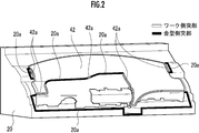
- FIG. 2 is an explanatory diagram showing the first mold and the work body of the present embodiment.
- FIG. 3 is an explanatory view showing the through hole of the present embodiment in an enlarged manner.
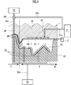
- FIG. 4 is an explanatory diagram showing the suction force in the bonding step of this embodiment.
- FIG. 5 is an explanatory view showing the work-side protrusion of this embodiment.
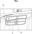
- FIG. 6 is an explanatory view showing the mesh-shaped groove portions and the through holes of this embodiment.
- FIG. 7 is an explanatory view showing the groove portion and the through hole of the present embodiment in an enlarged manner.
- FIG. 8 is an explanatory view showing the groove portion and the sheet material of the present embodiment in an enlarged manner.
- FIG. 9 is an explanatory diagram schematically showing a shutter device as a comparative example.
- the laminated work molding apparatus 1 of the present embodiment includes a first mold 20 and a second mold 30.
- a laminated work 40 such as an instrument panel formed by the laminated work forming apparatus 1 includes a work body 42 and a sheet material 44 laminated on the work body 42.
- the laminated work forming apparatus 1 includes a plurality of clamps 2 that grip the peripheral edge of the sheet material 44.
- FIG. 2 shows a state where the work main body 42 is placed on the first mold 20.
- the first mold 20 is provided with a plurality of suction holes 22 that are open to the mounting surface on which the work body 42 is mounted.
- a pattern composed of unevenness such as grain and satin for transferring to the surface of the sheet material 44 is formed.
- the second die 30 When the second die 30 is superposed on the first die 20 with the work body 42 and the sheet material 44 sandwiched between them, the second die 30 is positioned at the peripheral portion of the work body 42 and has a mesh shape (Fig. 6), a plurality of groove portions 31 are provided. Further, the second mold 30 is provided with a through hole 32 penetrating so as to open to the groove 31 for each groove 31.
- the second die 30 is provided with a plurality of ejection holes 34 which are penetrated so as to open at the central portion of the work body 42, which is a portion excluding the periphery of the work body 42.
- a first suction device 51 for sucking the sheet material 44 is connected to the through hole 32 via a first connection pipe 51a.
- a second suction device 52 for sucking the work body 42 is connected to the suction hole 22 via a second connection pipe 52a.
- a gas supply device 53 that supplies a gas such as air is connected to the ejection hole 34 through a third connection pipe 53a.
- a bypass passage 53b is connected to the first connecting pipe 51a and the third connecting pipe 53a.
- a flow path switching valve 54 is provided at a connection portion between the third connection pipe 53a and the bypass passage 53b.
- the flow path switching valve 54 connects the gas supply device 53 to the ejection hole 34 via the third connecting pipe 53a and disconnects the connection between the ejection hole 34 and the first suction device 51 via the bypass passage 53b.
- "State" the first suction device 51 is connected to the ejection hole 34 via the third connection pipe 53a, the bypass passage 53b, and the first connection pipe 51a, and the connection between the ejection hole 34 and the gas supply device 53 is cut off. It is configured so as to be switchable between two states of "suctionable state".
- the first die 20 and the work body 42 include a plurality of die-side protrusions 20 a protruding toward the second die 30 and a plurality of work-side protrusions 42 a.
- the through holes 32 are provided so as to surround the through holes 32 and extend along the outer edge of the bonding region of the sheet material 44.
- the sheet is fed from the gas supply device 53 through the ejection holes 34.
- the gas supplied to the surface of the material 44 and the sheet material 44 is peeled off from the second mold 30
- the gas supplied to the surface of the sheet material 44 directly flows into the through hole 32 and is sucked from the first suction device 51. If so, the suction performance of the sheet material 44 by the first suction device 51 is deteriorated.
- the gas supplied from the gas supply device 53 to the surface of the sheet material 44 is provided by providing the mold side projection 20a and the work side projection 42a so as to surround the through hole 32. Can be suppressed or prevented from flowing into the through hole 32, and deterioration of the suction performance of the sheet material 44 by the first suction device 51 can be suppressed or prevented.
- the second mold 30 may be provided with a mold-side protrusion instead of the mold-side protrusion 20a and the work-side protrusion 42a.
- the laminated work forming apparatus 1 includes a control unit 61 that controls the first suction device 51, the second suction device 52, the gas supply device 53, and the flow path switching valve 54.
- the control unit 61 is an electronic control unit configured by a CPU, a memory, and the like, and executes the control program held in the storage unit such as the memory by the CPU to transmit an instruction signal, thereby the first suction device 51, The second suction device 52, the gas supply device 53, and the flow path switching valve 54 are controlled.
- the first mold 20 and the second mold 30 are opened, and the work body 42 is placed on the first mold 20. Then, the sheet material 44 gripped by the clamp 2 is arranged between the work body 42 and the second mold 30. Then, the first mold 20 and the second mold 30 are brought into close proximity to each other to be in a closed state.
- control unit 61 connects the flow path switching valve 54 to the “suctionable state” (connects the first suction device 51 to the ejection hole 34 via the third connection pipe 53a, the bypass passage 53b, and the first connection pipe 51a. Then, the connection between the ejection hole 34 and the gas supply device 53 is switched to a state), and the sheet material 44 is sucked by the first suction device 51 through the groove portion 31, the through hole 32, and the ejection hole 34, and the second gold is removed. It is attached to the inner surface of the mold 30. As a result, the pattern formed on the inner surface of the second mold 30 can be transferred to the surface of the sheet material 44 (transfer step).
- the sheet material 44 is pressed against the work body 42 to be bonded by the suction force of the second suction device 52 (bonding step).
- the sheet material 44 is not adhered to the entire surface of the work body 42, but is adhered only to a portion exposed when the automobile or the like is assembled. In order to prevent improper assembly, they are made non-adhesive without adhering, and only the adhering parts are cut and the non-adhering parts are discarded.
- the control unit 61 causes the flow path switching valve 54 to be in a “jettable state” (the gas supply device 53 is connected to the jet hole 34 via the third connection pipe 53a, and the bypass passage 53b is provided).
- the control unit 61 causes the flow path switching valve 54 to be in a “jettable state” (the gas supply device 53 is connected to the jet hole 34 via the third connection pipe 53a, and the bypass passage 53b is provided).
- the connection between the ejection hole 34 and the first suction device 51 is cut off, and gas is supplied between the sheet material 44 and the second mold 30 by the gas supply device 53 via the ejection hole 34,
- the sheet material 44 is peeled off from the second mold 30.
- the control unit 61 sucks the sheet material 44 toward the second mold 30 side through the groove 31 and the through hole 32 by the first suction device 51, and the sheet material 44 is sucked.
- the second mold 30 is made to suck the part of the work piece 44 which is not adhered to the work body 42.
- the groove portion 31 can secure a gap between the groove material 31 and the sheet material 44. The overall suction force of the groove 31 can be appropriately maintained.
- the controller 61 has a stronger suction force for sucking the sheet material 44 from the through hole 32 than a suction force for sucking the work body 42 from the suction hole 22.
- the suction forces of the first suction device 51 and the second suction device 52 are set. By setting the suction force in this way, the sheet material 44 in the non-bonded portion can be appropriately attracted to the second mold 30.
- the non-adhesive portion located on the periphery of the work body 42 is sucked by the first suction device 51 through the through hole 32, as shown as a comparative example in FIG. It is not necessary to provide the shutter device 100' that prevents the sheet material 44 from adhering. Therefore, it is not necessary to arrange the clamps outside the shutter device 100′ so as to avoid the shutter device 100′ and to prepare a wide sheet material 44, and it is possible to reduce the amount of the discarded portion of the sheet material 44. Therefore, the manufacturing cost of the laminated work 40 can be suppressed. Further, the installation cost of the shutter device 100 ′ and the maintenance cost of the shutter device 100 ′ are not generated, and the cost of the laminated work forming device 1 can be suppressed.
- the gas supply device 53 via the ejection hole 34.
- the gas supplied to the surface of the sheet material 44 from the second mold 30 to peel off the sheet material 44 the gas supplied to the surface of the sheet material 44 flows to the through hole 32 as it is and the first suction device 51
- the suction performance of the sheet material 44 by the first suction device 51 deteriorates.
- the gas supplied from the gas supply device 53 to the surface of the sheet material 44 is provided by providing the mold side projection 20a and the work side projection 42a so as to surround the through hole 32. Can be suppressed or prevented from flowing into the through hole 32, and deterioration of the suction performance of the sheet material 44 by the first suction device 51 can be suppressed or prevented.
- the second mold 30 may be provided with a mold-side protrusion instead of the mold-side protrusion 20a and the work-side protrusion 42a.
- the groove portion 31 is provided by suction by the first suction device 51 through one through hole 32.
- the generated wide area can be sucked, and the number of through holes 32 per unit area of the inner surface of the second mold 30 can be reduced.
- the mesh-shaped groove portion 31 has been described in the present embodiment, the shape of the groove portion of the present invention is not limited to the mesh shape.
- the groove may be formed in another shape such as a linear shape, an H shape, a C shape, an X shape, or a spiral shape.
- Laminated Work Forming Device 2 Clamp 20 First Mold 20a Mold Side Projection 22 Suction Hole 30 Second Mold 31 Groove 32 Through Hole 34 Jet Hole 36 Recess 40 Laminated Work 42 Work Body 42a Work Side Projection 44 Sheet Material 51 first suction device 51a first connection pipe 52 second suction device 52a second connection pipe 53 gas supply device 53a third connection pipe 53b bypass passage 54 flow path switching valve 61 controller 100' shutter device X non-bonding region Y bonding region
Landscapes
- Engineering & Computer Science (AREA)
- Mechanical Engineering (AREA)
- Physics & Mathematics (AREA)
- Fluid Mechanics (AREA)
- Manufacturing & Machinery (AREA)
- Moulds For Moulding Plastics Or The Like (AREA)
- Lining Or Joining Of Plastics Or The Like (AREA)
Abstract
製造コストを抑えることができる積層ワーク成形装置を提供する。積層ワーク成形装置1は、ワーク本体42を吸着保持する第1金型20と、ワーク本体42に積層されるシート材44の表面に転写可能な模様を内面に有し、且つシート材42をワーク本体42に押し付ける第2金型30と、を備える。第2金型30の内面には、ワーク本体42の周縁部に位置させて溝部31が設けられ、第2金型30には、溝部31に開口するように貫通する貫通孔32が設けられ、貫通孔32には、シート材44を吸引する第1吸引装置51が接続され、第1金型20には、ワーク本体42を吸着させるための吸引孔22が設けられ、吸引孔22には、第2吸引装置52が接続されている。
Description
本発明は、積層ワーク成形装置に関する。
従来、ワーク本体とワーク本体に積層されるシート材とで構成される積層ワークを、ワーク本体を吸着保持する第1金型を用いて成形する積層ワーク成形装置が知られている(例えば、日本国特開平7-24909号公報参照)。
特許文献1のものでは、ワーク本体の中央部に形成された逃げ凹部にシート材が引き込まれて破れることがないように逃げ凹部をシャッターで閉塞している。
また、逃げ凹部を覆うシャッターを設けるとワーク本体のレイアウト自由度が制限されるため、ワーク本体の中央部に形成された逃げ凹部に位置させて、シート材をワーク本体から離す方向に吸引する吸引装置を設けたものも知られている(例えば、日本国特開2000-218688号公報参照)。
特許文献1の積層ワーク成形装置は、シート材の表面に転写可能な模様を内面に有する第2金型を用いる場合、シート材を第2金型で吸着して模様を転写した後、ワーク本体を吸着する第1金型と第2金型とを重ね合わせるようにして、シート材をワーク本体に貼り付けるときに、シート材が第2金型から剥がれ易くするために空気などの流体を第2金型から噴出させることが考えられる。
この場合、特許文献1のようにワーク本体の中央部の逃げ凹部に位置させてシート材をワーク本体から離す方向に吸引する吸引装置を設けることができない。従って、ワーク本体のレイアウト自由度を向上させるためには、逃げ凹部に入子を配置することが考えられる。
また、ワーク本体のレイアウト自由度に影響を与えないワーク本体の周縁では、シャッター装置を設けて、ワーク本体の周縁においてシート材を貼り付けない場所にシート材が張り付くことを防止することが考えられる。
しかしながら、ワーク本体の周縁にシャッター装置を設けると、シート材はシャッター装置の外側に配置されたクランプで把持されるため、シャッター装置の分だけ大きなシート材を用意する必要があり、また、シャッター装置の設置費用及びシャッター装置のメンテナンス費用などが嵩み、コストを抑えることができないという問題がある。
本発明は、以上の点に鑑み、コストを抑えることができる積層ワーク成形装置を提供することを目的とする。
[1]上記目的を達成するため、本発明は、
ワーク本体を吸着保持する第1金型と、
前記ワーク本体に積層されるシート材の表面に転写可能な模様を内面に有し、且つ前記シート材を前記ワーク本体に押し付ける第2金型と、
を備える積層ワーク成形装置であって、
前記第2金型の内面には、前記ワーク本体の周縁部に位置させて溝部が設けられ、
前記第2金型には、前記溝部に開口するように貫通する貫通孔が設けられ、
前記貫通孔には、前記シート材を吸引する第1吸引装置が接続され、
前記第1金型には、ワーク本体を吸着させるための吸引孔が設けられ、
前記吸引孔には、第2吸引装置が接続されていることを特徴とする。
ワーク本体を吸着保持する第1金型と、
前記ワーク本体に積層されるシート材の表面に転写可能な模様を内面に有し、且つ前記シート材を前記ワーク本体に押し付ける第2金型と、
を備える積層ワーク成形装置であって、
前記第2金型の内面には、前記ワーク本体の周縁部に位置させて溝部が設けられ、
前記第2金型には、前記溝部に開口するように貫通する貫通孔が設けられ、
前記貫通孔には、前記シート材を吸引する第1吸引装置が接続され、
前記第1金型には、ワーク本体を吸着させるための吸引孔が設けられ、
前記吸引孔には、第2吸引装置が接続されていることを特徴とする。
本発明によれば、ワーク本体の周縁のシート材は第1吸引装置で吸引するため、ワーク本体の周縁にシャッター装置を配置する必要がない。このため、シャッター装置を省略できる分だけ小さいシート材で積層ワークを成形することができ、積層ワークの製造コストを抑えることができ、且つ成形装置自体のコストも抑えることができる積層ワーク成形装置を提供することができる。
また、貫通孔は、第2金型の内面に設けられた溝部に開口しているため、1つの貫通孔を介した第1吸引装置による吸引で溝部が設けられた広範囲を吸引することができ、単位面積当たりにおける貫通孔の数を減少させることができる。
[2]また、本発明においては、前記溝部は、網目状に設けられていることが好ましい。かかる構成によれば、直線状に溝部を形成した場合と比較して、1つの貫通孔で更に広範囲を吸引することができ、単位面積当たりにおける貫通孔の数を減少させることができる。
[3、4]また、本発明においては、
前記第1吸引装置と前記第2吸引装置の吸引力を設定する制御部を備え、
前記制御部は、前記ワーク本体に前記シート材を接着させる接着工程において、前記第1吸引装置の吸引力を、前記第2吸引装置の吸引力よりも強く設定することが好ましい。
前記第1吸引装置と前記第2吸引装置の吸引力を設定する制御部を備え、
前記制御部は、前記ワーク本体に前記シート材を接着させる接着工程において、前記第1吸引装置の吸引力を、前記第2吸引装置の吸引力よりも強く設定することが好ましい。
本発明によれば、非接着部分のシート材を適切に第2金型の側へ引き付けさせることができる。
図を参照して、本発明の積層ワーク成形装置の実施形態を説明する。図1を参照して、本実施形態の積層ワーク成形装置1は、第1金型20と、第2金型30とを備える。積層ワーク成形装置1で成形されるインストルメントパネルなどの積層ワーク40は、ワーク本体42と、ワーク本体42に積層されるシート材44とを備える。
積層ワーク成形装置1は、シート材44の周縁を把持する複数のクランプ2を備えている。
図2は、第1金型20にワーク本体42が載置された状態を示している。
図3に示すように、第1金型20には、ワーク本体42が載置される載置面に開口する複数の吸引孔22が設けられている。第2金型30の内面には、シート材44の表面に転写するためのシボや梨地などの凹凸で構成された模様が形成されている。
第2金型30には、第2金型30をワーク本体42及びシート材44を挟んで第1金型20に重ね合わせたときに、ワーク本体42の周縁部に位置させて網目状(図6参照)の溝部31が複数設けられている。また、第2金型30には、溝部31に開口するように貫通させた貫通孔32が夫々の溝部31に対して1つずつ設けられている。
また、第2金型30には、ワーク本体42の周縁を除いた部分であるワーク本体42の中央部の位置に開口するように貫通させた複数の噴出孔34が設けられている。
貫通孔32には、シート材44を吸引するための第1吸引装置51が第1接続配管51aを介して接続されている。吸引孔22にはワーク本体42を吸引するための第2吸引装置52が第2接続配管52aを介して接続されている。噴出孔34には、空気などの気体を供給する気体供給装置53が第3接続配管53aを介して接続されている。
第1接続配管51aと第3接続配管53aには、バイパス路53bが接続されている。第3接続配管53aとバイパス路53bの接続部分には、流路切換弁54が設けられている。流路切換弁54は、噴出孔34に第3接続配管53aを介して気体供給装置53を接続し、バイパス路53bを介した噴出孔34と第1吸引装置51との接続を断つ「噴出可能状態」と、噴出孔34に第3接続配管53a、バイパス路53b、および第1接続配管51aを介して第1吸引装置51を接続し、噴出孔34と気体供給装置53との接続を断つ「吸引可能状態」との2つの状態に切り替え自在に構成されている。
また、図2を参照して、第1金型20と、ワーク本体42とには、第2金型30に向かって突出する金型側突部20aと、ワーク側突部42aが、複数の貫通孔32を囲うようにして、シート材44の接着領域の外縁に沿うように延在して、夫々設けられている。
仮に、金型側突部20aと、ワーク側突部42aが設けられていないと仮定すると、ワーク本体42にシート材44を接着する接着工程において、噴出孔34を介して気体供給装置53からシート材44の表面に気体を供給して第2金型30からシート材44を剥がす場合には、シート材44の表面に供給された気体がそのまま貫通孔32へ流れて第1吸引装置51から吸引されると、第1吸引装置51によるシート材44の吸引性能が低下してしまう。
そこで、上述したように本実施形態では、貫通孔32を囲うように金型側突部20a及びワーク側突部42aを設けることにより、気体供給装置53からシート材44の表面に供給される気体が貫通孔32へ流れることを抑制又は防止することができ、第1吸引装置51によるシート材44の吸引性能の低下を抑制又は防止することができる。なお、金型側突部20a及びワーク側突部42aに代えて、第2金型30に金型側突部を設けてもよい。
図3に示すように、積層ワーク成形装置1は、第1吸引装置51、第2吸引装置52、気体供給装置53、流路切換弁54を制御する制御部61を備える。制御部61は、CPUやメモリ等により構成された電子制御ユニットであり、メモリなどの記憶部に保持された制御プログラムをCPUで実行して指示信号を送信することにより、第1吸引装置51、第2吸引装置52、気体供給装置53、流路切換弁54を制御する。
次に、積層ワーク成形装置1を用いた積層ワーク成形方法を説明する。
まず、第1金型20及び第2金型30を開いた状態とし、第1金型20にワーク本体42を載置する。そして、クランプ2で把持されたシート材44をワーク本体42と第2金型30との間に配置させる。そして、第1金型20及び第2金型30を互いに接近するようにして閉じた状態とする。
次に、制御部61は、流路切換弁54を「吸引可能状態」(噴出孔34に第3接続配管53a、バイパス路53b、および第1接続配管51aを介して第1吸引装置51を接続し、噴出孔34と気体供給装置53との接続を断つ状態)に切り換えて、溝部31、貫通孔32及び噴出孔34を介して第1吸引装置51でシート材44を吸引して第2金型30の内面に貼り付けさせる。これにより、第2金型30の内面に形成された模様をシート材44の表面に転写することができる(転写工程)。
次に、ワーク本体42又はシート材44に接着剤を塗布した状態で、シート材44をワーク本体42に押し付けるようにして第2吸引装置52の吸引力で接着させる(接着工程)。
ここで、シート材44は、ワーク本体42の表面の全てに接着させるわけではなく、自動車などの組み立てたときに露出する部分にのみ接着させ、組み付け時に他の部品に隠れる周縁などの部分については組み付け不良を防ぐべく接着させずに非接着とし、接着部分のみを残して切断され非接着の部分は廃棄される。
そして、接着工程においては、制御部61は、流路切換弁54を「噴出可能状態」(噴出孔34に第3接続配管53aを介して気体供給装置53を接続し、バイパス路53bを介した噴出孔34と第1吸引装置51との接続を断つ状態)に切り換えて、噴出孔34を介して気体供給装置53でシート材44と第2金型30との間に気体を供給して、シート材44が第2金型30から剥がれるようにする。
また、図7に拡大して示すように、制御部61は、第1吸引装置51によって、溝部31及び貫通孔32を介してシート材44を第2金型30の側へ吸引し、シート材44のワーク本体42に非接着とさせる部分を第2金型30に吸い付けさせる。このとき、図8に溝部31を拡大して示すように、シート材44が第2金型30の内面に張り付いても溝部31はシート材44との間に隙間を確保することができ、溝部31の全体的な吸引力を適切に保持することができる。
このとき、制御部61は、図4の非接着領域Xで示すように、貫通孔32からシート材44を吸引する吸引力が、吸引孔22からワーク本体42を吸引する吸引力よりも強くなるように、第1吸引装置51と第2吸引装置52の吸引力を設定している。このように吸引力を設定することにより、非接着部分のシート材44を適切に第2金型30へ引き付けさせることができる。
このように、ワーク本体42の周縁に位置する非接着の部分が貫通孔32を介して第1吸引装置51で吸引されるため、図9に比較例として示すように、ワーク本体42の周縁にシート材44の接着を防ぐシャッター装置100’を設ける必要がない。このため、シャッター装置100’を避けるようにしてシャッター装置100’の外側にクランプを配置して、広いシート材44を用意する必要がなく、シート材44の廃棄部分の量を低減させることができ、積層ワーク40の製造コストを抑えることができる。また、シャッター装置100’の設置費用及びシャッター装置100’のメンテナンス費用も発生せず、積層ワーク成形装置1のコストを抑えることができる。
また、仮に、金型側突部20aと、ワーク側突部42aが設けられていないと仮定すると、ワーク本体42にシート材44を接着する接着工程において、噴出孔34を介して気体供給装置53からシート材44の表面に気体を供給して第2金型30からシート材44を剥がす場合には、シート材44の表面に供給された気体がそのまま貫通孔32へ流れて第1吸引装置51から吸引されると、第1吸引装置51によるシート材44の吸引性能が低下してしまう。
そこで、上述したように本実施形態では、貫通孔32を囲うように金型側突部20a及びワーク側突部42aを設けることにより、気体供給装置53からシート材44の表面に供給される気体が貫通孔32へ流れることを抑制又は防止することができ、第1吸引装置51によるシート材44の吸引性能の低下を抑制又は防止することができる。なお、金型側突部20a及びワーク側突部42aに代えて、第2金型30に金型側突部を設けてもよい。
また、貫通孔32は、第2金型30の内面に設けられた網目状の溝部31に開口しているため、1つの貫通孔32を介した第1吸引装置51による吸引で溝部31が設けられた広範囲を吸引することができ、第2金型30の内面の単位面積当たりにおける貫通孔32の数を減少させることができる。なお、本実施形態においては網目状の溝部31を説明したが、本発明の溝部の形状は網目状に限らない。例えば、溝部を、直線状や、H字状、C字状、X字状、螺旋状などの他の形状に形成してもよい。
1 積層ワーク成形装置
2 クランプ
20 第1金型
20a 金型側突部
22 吸引孔
30 第2金型
31 溝部
32 貫通孔
34 噴出孔
36 凹部
40 積層ワーク
42 ワーク本体
42a ワーク側突部
44 シート材
51 第1吸引装置
51a 第1接続配管
52 第2吸引装置
52a 第2接続配管
53 気体供給装置
53a 第3接続配管
53b バイパス路
54 流路切換弁
61 制御部
100’ シャッター装置
X 非接着領域
Y 接着領域
2 クランプ
20 第1金型
20a 金型側突部
22 吸引孔
30 第2金型
31 溝部
32 貫通孔
34 噴出孔
36 凹部
40 積層ワーク
42 ワーク本体
42a ワーク側突部
44 シート材
51 第1吸引装置
51a 第1接続配管
52 第2吸引装置
52a 第2接続配管
53 気体供給装置
53a 第3接続配管
53b バイパス路
54 流路切換弁
61 制御部
100’ シャッター装置
X 非接着領域
Y 接着領域
Claims (4)
- ワーク本体を吸着保持する第1金型と、
前記ワーク本体に積層されるシート材の表面に転写可能な模様を内面に有し、且つ前記シート材を前記ワーク本体に押し付ける第2金型と、
を備える積層ワーク成形装置であって、
前記第2金型の内面には、前記ワーク本体の周縁部に位置させて溝部が設けられ、
前記第2金型には、前記溝部に開口するように貫通する貫通孔が設けられ、
前記貫通孔には、前記シート材を吸引する第1吸引装置が接続され、
前記第1金型には、ワーク本体を吸着させるための吸引孔が設けられ、
前記吸引孔には、第2吸引装置が接続されていることを特徴とする積層ワーク成形装置。 - 請求項1に記載の積層ワーク成形装置であって、
前記溝部は、網目状に設けられていることを特徴とする積層ワーク成形装置。 - 請求項1に記載の積層ワーク成形装置であって、
前記第1吸引装置と前記第2吸引装置の吸引力を設定する制御部を備え、
前記制御部は、前記ワーク本体に前記シート材を接着させる接着工程において、前記第1吸引装置の吸引力を、前記第2吸引装置の吸引力よりも強く設定することを特徴とする積層ワーク成形装置。 - 請求項2に記載の積層ワーク成形装置であって、
前記第1吸引装置と前記第2吸引装置の吸引力を設定する制御部を備え、
前記制御部は、前記ワーク本体に前記シート材を接着させる接着工程において、前記第1吸引装置の吸引力を、前記第2吸引装置の吸引力よりも強く設定することを特徴とする積層ワーク成形装置。
Priority Applications (3)
| Application Number | Priority Date | Filing Date | Title |
|---|---|---|---|
| CN201980083306.9A CN113226701B (zh) | 2019-01-23 | 2019-11-01 | 层叠工件成型装置 |
| US17/424,718 US20220009135A1 (en) | 2019-01-23 | 2019-11-01 | Stacked workpiece molding device |
| JP2020567371A JP7047141B2 (ja) | 2019-01-23 | 2019-11-01 | 積層ワーク成形装置 |
Applications Claiming Priority (2)
| Application Number | Priority Date | Filing Date | Title |
|---|---|---|---|
| JP2019-009244 | 2019-01-23 | ||
| JP2019009244 | 2019-01-23 |
Publications (1)
| Publication Number | Publication Date |
|---|---|
| WO2020152934A1 true WO2020152934A1 (ja) | 2020-07-30 |
Family
ID=71736361
Family Applications (1)
| Application Number | Title | Priority Date | Filing Date |
|---|---|---|---|
| PCT/JP2019/043122 Ceased WO2020152934A1 (ja) | 2019-01-23 | 2019-11-01 | 積層ワーク成形装置 |
Country Status (4)
| Country | Link |
|---|---|
| US (1) | US20220009135A1 (ja) |
| JP (1) | JP7047141B2 (ja) |
| CN (1) | CN113226701B (ja) |
| WO (1) | WO2020152934A1 (ja) |
Families Citing this family (3)
| Publication number | Priority date | Publication date | Assignee | Title |
|---|---|---|---|---|
| US20190291333A1 (en) * | 2015-08-14 | 2019-09-26 | Scrape Armor, Inc. | System and method for forming of 3d plastic parts |
| JP7106684B2 (ja) * | 2019-01-23 | 2022-07-26 | 本田技研工業株式会社 | 積層ワーク |
| ES3019907T3 (en) * | 2020-02-27 | 2025-05-21 | Essilor Int | A thermoforming machine and method |
Citations (2)
| Publication number | Priority date | Publication date | Assignee | Title |
|---|---|---|---|---|
| JPS56157329A (en) * | 1980-05-08 | 1981-12-04 | Meiwa Sangyo Kk | Production of composite formed article |
| JP2010179477A (ja) * | 2009-02-03 | 2010-08-19 | Kasai Kogyo Co Ltd | 積層成形品の製造方法並びにその方法に使用する成形金型 |
Family Cites Families (4)
| Publication number | Priority date | Publication date | Assignee | Title |
|---|---|---|---|---|
| JP3241174B2 (ja) * | 1993-07-12 | 2001-12-25 | 本田技研工業株式会社 | 吸引型 |
| US5572786A (en) * | 1995-09-11 | 1996-11-12 | Aluminum Company Of America | Method for holding a workpiece by vacuum |
| US5993724A (en) * | 1997-12-31 | 1999-11-30 | Lyle H. Shuert | Method of forming non-skid plastic pallet |
| JP4765599B2 (ja) * | 2005-12-12 | 2011-09-07 | トヨタ車体株式会社 | 真空成形方法及びその装置 |
-
2019
- 2019-11-01 WO PCT/JP2019/043122 patent/WO2020152934A1/ja not_active Ceased
- 2019-11-01 US US17/424,718 patent/US20220009135A1/en not_active Abandoned
- 2019-11-01 JP JP2020567371A patent/JP7047141B2/ja not_active Expired - Fee Related
- 2019-11-01 CN CN201980083306.9A patent/CN113226701B/zh not_active Expired - Fee Related
Patent Citations (2)
| Publication number | Priority date | Publication date | Assignee | Title |
|---|---|---|---|---|
| JPS56157329A (en) * | 1980-05-08 | 1981-12-04 | Meiwa Sangyo Kk | Production of composite formed article |
| JP2010179477A (ja) * | 2009-02-03 | 2010-08-19 | Kasai Kogyo Co Ltd | 積層成形品の製造方法並びにその方法に使用する成形金型 |
Also Published As
| Publication number | Publication date |
|---|---|
| CN113226701A (zh) | 2021-08-06 |
| JP7047141B2 (ja) | 2022-04-04 |
| JPWO2020152934A1 (ja) | 2021-09-30 |
| US20220009135A1 (en) | 2022-01-13 |
| CN113226701B (zh) | 2023-03-24 |
Similar Documents
| Publication | Publication Date | Title |
|---|---|---|
| WO2020152934A1 (ja) | 積層ワーク成形装置 | |
| JP2009238881A (ja) | 電子部品の剥離方法及び剥離装置 | |
| JP5032563B2 (ja) | 少なくとも1つの貫通開口を備えるワークピースを取り扱う方法および機械アッセンブリ | |
| WO2020152931A1 (ja) | 積層ワーク成形方法及びその装置 | |
| JP2017092313A (ja) | 半導体製造装置。 | |
| TWI466224B (zh) | 基板貼合裝置 | |
| CN107210248A (zh) | 用于夹紧工件的真空夹紧装置 | |
| JP7106684B2 (ja) | 積層ワーク | |
| CN113905870A (zh) | 层叠工件成型装置 | |
| JP7186895B2 (ja) | 積層ワーク成形方法、及びその装置 | |
| JP2010267746A5 (ja) | ||
| JP2009105226A (ja) | 保持用治具、取り外し補助装置、物品搬送設備、物品の取り外し方法 | |
| CN109275282B (zh) | 电路板的装配方法、电路板及电子设备 | |
| TW201352096A (zh) | 拆板總成及其操作方法 | |
| JP2006276669A (ja) | 粘着チャック装置及びそれを備えた基板貼り合わせ機 | |
| JP5795523B2 (ja) | 成形方法 | |
| JP5169543B2 (ja) | 半導体チップの実装装置 | |
| JP2006156793A (ja) | フレキシブル基板の剥離装置 | |
| CN115552322B (zh) | 工件粘附保持盘装置及工件贴合机 | |
| JP2021037710A (ja) | 機能性フィルムのワークへの貼付方法及びそのワークの剥離方法並びにそれに用いる貼付装置 | |
| JP2011210799A (ja) | 可撓性部材の位置決め装置及び方法 | |
| JP2009059790A (ja) | 基板搬送方法及びそれに用いられる基板搬送治具 | |
| JP2018206830A (ja) | 電子デバイスの製造方法及びこれに用いる通気性シート | |
| KR20160031329A (ko) | 디스플레이 장치용 시트부재 척킹 및 디척킹 장치 | |
| JP2008041943A (ja) | 組立装置 |
Legal Events
| Date | Code | Title | Description |
|---|---|---|---|
| 121 | Ep: the epo has been informed by wipo that ep was designated in this application |
Ref document number: 19911245 Country of ref document: EP Kind code of ref document: A1 |
|
| ENP | Entry into the national phase |
Ref document number: 2020567371 Country of ref document: JP Kind code of ref document: A |
|
| NENP | Non-entry into the national phase |
Ref country code: DE |
|
| 122 | Ep: pct application non-entry in european phase |
Ref document number: 19911245 Country of ref document: EP Kind code of ref document: A1 |