WO2020152887A1 - 鋼板、テーラードブランク、熱間プレス成形品、鋼管、中空状焼入れ成形品、および鋼板の製造方法 - Google Patents
鋼板、テーラードブランク、熱間プレス成形品、鋼管、中空状焼入れ成形品、および鋼板の製造方法 Download PDFInfo
- Publication number
- WO2020152887A1 WO2020152887A1 PCT/JP2019/028402 JP2019028402W WO2020152887A1 WO 2020152887 A1 WO2020152887 A1 WO 2020152887A1 JP 2019028402 W JP2019028402 W JP 2019028402W WO 2020152887 A1 WO2020152887 A1 WO 2020152887A1
- Authority
- WO
- WIPO (PCT)
- Prior art keywords
- steel plate
- steel sheet
- exposed
- base material
- steel
- Prior art date
Links
Images


Classifications
-
- B—PERFORMING OPERATIONS; TRANSPORTING
- B23—MACHINE TOOLS; METAL-WORKING NOT OTHERWISE PROVIDED FOR
- B23K—SOLDERING OR UNSOLDERING; WELDING; CLADDING OR PLATING BY SOLDERING OR WELDING; CUTTING BY APPLYING HEAT LOCALLY, e.g. FLAME CUTTING; WORKING BY LASER BEAM
- B23K31/00—Processes relevant to this subclass, specially adapted for particular articles or purposes, but not covered by only one of the preceding main groups
Definitions
- the present disclosure relates to a steel plate, a tailored blank, a hot press-formed product, a steel pipe, a hollow quenched product, and a method for manufacturing a steel plate.
- the present application claims priority based on International Application PCT/JP2019/001922 filed on January 22, 2019, the content of which is incorporated herein by reference.
- hot press molding As one of the technologies for molding automobile members, hot press molding (hereinafter, sometimes referred to as “hot stamp”) has been attracting attention.
- hot stamping a steel sheet is heated to a high temperature, press-formed in a temperature range of Ar 3 transformation temperature or higher, rapidly cooled by heat removal by a die, and transformation occurs simultaneously with forming under a press pressure.
- This is a technique capable of producing a press-formed product (hereinafter, also referred to as “hot stamp-formed product”) having high strength and excellent shape fixability.
- At least two steel plates are butt-joined and joined together by laser welding, plasma welding, or the like (hereinafter referred to as "tailored blank”). Is sometimes referred to as ".” is applied as a material for pressing. Since the tailored blank joins a plurality of steel plates depending on the purpose, it becomes possible to freely change the plate thickness and strength in one component. As a result, the tailored blank can improve the functionality of the automobile member and reduce the number of automobile members. Further, by hot stamping using a tailored blank, it is possible to manufacture a high-strength press-formed product in which the plate thickness, strength, etc. are freely changed.
- a tailored blank When a tailored blank is used as a press material and an automobile member is formed by hot stamping, the tailored blank is heated to a temperature range of, for example, 800°C to 1000°C. For this reason, in a tailored blank for hot stamping, a steel plate plated with aluminum such as Al-Si having a high plating boiling point is often used.
- the conventional steel sheet did not fully satisfy both the static tensile strength of the joint and the post-painting corrosion resistance of the weld metal during butt welding, and there was room for further improvement.
- An object of the present disclosure is, when butt welding, excellent in static tensile strength of a joint, and even after coating on a weld metal portion, a steel plate excellent in corrosion resistance after coating around the weld metal portion, tailored.
- Base material steel plate a plating part in which an aluminum coating layer including an intermetallic compound layer and an aluminum plating layer is provided on the surface of the base material steel plate, and the base material steel plate in the thickness direction of the steel plate Or an exposed portion where the intermetallic compound layer is exposed, and a steel plate that is perpendicular to the thickness direction of the steel plate, and in the first direction from the plated portion toward one edge of the steel plate, the mother At least the plated portion, the exposed portion, and the edge of the steel sheet are arranged in this order on the surface of the material steel sheet, and in the first direction, from the edge surface of the plated portion to the edge of the steel sheet.
- the position where the length to the edge is the maximum value is the first position, and the plating part has a protruding part that is a part protruding from the first position to the edge side of the steel plate, and the protruding part Is a steel plate separated from the base steel plate in the thickness direction.
- an average thickness of the aluminum plating layer is 8 ⁇ m to 50 ⁇ m in the plated portion in a direction opposite to the first direction from the first position.
- the average thickness of the intermetallic compound layer is 1 ⁇ m to 10 ⁇ m in the plated portion in the direction opposite to the first direction from the first position.
- the value of the area Sa is the value when the unit is ⁇ m 2
- the value of W3 is the value when the unit is ⁇ m.
- n 1 in the equation (1).
- the base material steel sheet is, in mass %, C: 0.02% to 0.58%, Mn: 0.20% to 3.00%, Al: 0.005% to 0.06%, P : 0.03% or less, S: 0.010% or less, N: 0.010% or less, Ti: 0% to 0.20%, Nb: 0% to 0.20%, V: 0% to 1.
- ⁇ 7> A hot press molded product using the tailored blank according to ⁇ 6>.
- ⁇ 8> A steel pipe having a weld metal portion adjacent to the exposed portion of the steel sheet according to any one of ⁇ 1> to ⁇ 5>.
- ⁇ 9> A hollow quench-molded product using the steel pipe according to ⁇ 8>.
- ⁇ 10> A method for manufacturing a steel sheet according to any one of ⁇ 1> to ⁇ 5>, including a step of forming the exposed portion by machining.
- a tailored blank, a hot press-formed product, a steel pipe, a hollow quench-formed product, and a method for manufacturing a steel sheet are provided.
- the numerical range represented by “to” means a range including the numerical values before and after “to” as the lower limit value and the upper limit value.
- the content of the component (element) for example, in the case of the content of C (carbon), it may be expressed as “C amount”.
- the contents of other elements may be similarly expressed.
- the term “process” is used not only as an independent process, but also in the case where the intended purpose of the process is achieved even when it cannot be clearly distinguished from other processes. included.
- the term “aluminum coating layer” refers to the entire aluminum plating applied on both sides of the base steel sheet. That is, the aluminum coating layer represents the whole of the aluminum plating layer and the intermetallic compound layer.
- the term “intermetallic compound layer” refers to a layer of an intermetallic compound formed between a base material steel plate and aluminum plating when aluminum plating is applied to both surfaces of the base material steel plate. ..
- the term “aluminum plating layer” refers to a region of the aluminum plating applied on the base material steel sheet, excluding the intermetallic compound layer.
- the terms “base material steel sheet”, “intermetallic compound layer”, and “aluminum plating layer” are further described in “Definition of range of base material steel sheet, intermetallic compound layer, and aluminum plating layer” described later.
- the term “thickness direction” means the direction in which the plate thickness at the center of the plate width of the steel plate is measured.
- the term “end surface of the steel sheet” means a surface of the surface of the steel sheet that is exposed in a direction orthogonal to the thickness direction.
- the term “edge of steel sheet” means a portion adjacent to the end surface of the steel sheet.
- edge of steel plate means a region located around the periphery of the steel plate and, in the maximum case, a region within 7 mm from the edge of the steel plate. ..
- central portion of the steel sheet means a region other than the end portion of the steel sheet.
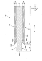
- cross section of the steel sheet represents a cross section cut in the thickness direction of the steel sheet. Specifically, in FIG. 1, the thickness direction of the steel sheet is Z, and the longitudinal direction of the exposed portion (direction orthogonal to the display surface of FIG. 1) is X. Then, the directions orthogonal to the directions Z and X are defined as Y.
- the cross section means a cross section cut along the YZ plane.
- welding portion refers to a region including a weld metal portion, an exposed portion of a steel plate located around the weld metal portion, and a periphery of the plated portion on the weld metal side.
- first direction (first direction) indicates a direction that is perpendicular to the thickness direction of the steel sheet and is a direction (Y direction) from the plated portion to one edge of the steel sheet.
- the steel plate of the present disclosure has a base material steel plate and aluminum coating layers provided on both surfaces of the base material steel plate. Further, on both sides of at least a part of the end portion located in the periphery, at least a part of the aluminum coating layer is removed (hereinafter, may be referred to as an exposed part), and the steel plate rather than the exposed part. A residual portion (hereinafter sometimes referred to as a plated portion) where the aluminum coating layer exists is formed in a region on the center side of the plate width.
- the steel sheet of the present disclosure is a base material steel sheet, a plating portion provided with an aluminum coating layer including an intermetallic compound layer and an aluminum plating layer on the surface of the base material steel sheet, and in the thickness direction of the steel sheet.
- the steel sheet of the present disclosure is perpendicular to the thickness direction of the steel sheet, and in the first direction from the plated portion to one edge of the steel sheet, at least the plated portion, the exposed portion, the steel sheet on the surface of the base steel sheet. Edges are arranged in this order.
- the steel sheet of the present disclosure has the shortest removal width (hereinafter, referred to as an exposure width when the boundary between the exposed portion and the plated portion is viewed from a cross section, on the aluminum coating layer outer surface side at the end surface of the plated portion. There is a portion having the longest exposed width on the inner side of the base material steel plate side with respect to the portion having the shortest removal width.
- the plated portion when the position where the length from the end surface of the plated portion on the edge side of the steel sheet to the edge of the steel sheet has the maximum value in the first direction is the first position, the plated portion is There is a protruding portion that is a portion protruding from the first position to the edge side of the steel sheet, and this protruding portion is separated from the base steel sheet in the thickness direction of the steel sheet.
- the shape of the steel sheet is not particularly limited.
- FIG. 1 is a schematic cross-sectional view showing an example of an end portion of a steel plate according to the present disclosure.
- FIG. 2 is a schematic cross-sectional view showing another example of the end portion of the steel sheet of the present disclosure.
- 100 is a steel plate
- 12 is a base material steel plate
- 14 is an aluminum plating layer
- 16 is an intermetallic compound layer
- 18 is an aluminum coating layer
- 22 is an exposed portion
- 26 is a plated portion.
- 100A is an end face of the steel plate
- 100B is a portion (position) having the shortest exposed width at the boundary between the exposed portion 22 and the plated portion 26
- 100D is a longest exposed width at the boundary between the exposed portion 22 and the plated portion 26. Shows the part (position).
- the portion 100B having the shortest exposure width at the boundary between the exposed portion 22 and the plated portion 26 (hereinafter, may be referred to as the end surface of the plated portion 26 on the edge side of the steel plate 100) is It is located at the outer edge of the aluminum coating layer 18 at the boundary between the exposed portion 22 and the plated portion 26.
- the aluminum coating layers 18 are formed on both surfaces of the base material steel plate 12. Further, the aluminum coating layer 18 has an aluminum plating layer 14 formed on both sides of the steel plate 100 and an intermetallic compound layer 16 formed between the base material steel plate 12 and the aluminum plating layer 14.
- exposed portions 22 are formed on both surfaces of the steel plate 100 at the end portions thereof, and a plated portion 26 is formed in a region closer to the plate width center of the steel plate 100 than the exposed portions 22. Has been done. Further, as shown in FIGS. 1 and 2, when the boundary between the exposed portion 22 and the plated portion 26 is viewed from cross sections parallel to the thickness direction of the steel sheet 100 and the first direction F1, respectively, the portion having the shortest exposed width (Position) 100B projects to the end surface 100A side of the steel plate 100.
- the end surface of the plated portion 26 on the edge side of the steel plate 100 is the most exposed end surface of the plated portion 26 on the edge side of the steel plate 100 from the portion 100B having the shortest exposed width on the end surface of the steel sheet 100 of the plated portion 26. It extends toward a portion (first position) 100D having a long exposure width.
- the cross-sectional shape of the end surface of the plated portion 26 on the edge side of the steel plate 100 is inclined toward the plated portion 26 side and has a concave shape.
- the boundary between the exposed portion 22 and the plated portion 26 (that is, the end surface of the plated portion 26) is provided on the outer surface side of the aluminum coating layer 18, and the protruding portion that protrudes toward the end surface side of the steel sheet 100 (for example, 100B Has a top portion) and a base material steel plate 12 side with respect to the projection portion, and a recess portion (for example, a recess portion having 100D as a bottom portion) recessed toward the center of the width of the steel plate 100. ..
- the end surface of the plated portion 26 on the edge side of the steel sheet 100 has a portion 100B where the outer surface side of the aluminum coating layer 18 has the shortest exposure width, and the base material steel sheet 12 side ( It is formed so as to have a portion 100D having the longest exposed width on the inner side of the base material steel plate 12 with respect to 100B).
- the steel plate 100 of the present disclosure includes the first region T1 in which the first plating layer 36A is provided on the base material steel plate 12. Then, the steel sheet 100 of the present disclosure is connected to the first plating layer 36A, and at least a portion protruding from the first region T1 toward the end surface 100A side of the steel sheet 100 while being separated from the base material steel sheet 12 in the thickness direction of the steel sheet 100.
- the second region T2 provided with the second plating layer 36B is provided.
- the second region T2 is a region from the position 100D having the longest exposure width W2 (first position) 100D to the position 100B having the shortest exposure width W1 in the first direction F1.
- the portion protruding from the first region T1 (that is, the portion protruding from the first position 100D) is separated from the base material steel plate 12 in the thickness direction.
- “separated” means that a gap exists between the protruding portion and the base material steel plate 12, and at least the protruding portion in the thickness direction of the steel plate 100, the gap, and the base material steel plate 12 are in this order. It exists.
- the plating layer 36B in the second region T2 is composed of the portion protruding from the first region T1 and the intermetallic compound layer 16 existing immediately above the base material steel plate 12.
- the steel plate 100 of the present disclosure includes a third region T3 adjacent to the end surface of the steel plate 100 and in which the base steel plate 12 is exposed in the thickness direction of the steel plate 100.
- the steel plate 100 of the present disclosure includes the third region T3 in which the third plating layer 36C thinner than the first plating layer 36B is provided on the base material steel plate 12.
- the third region T3 indicates a region from the position 100B having the shortest exposure width W1 to the edge of the steel plate 100 in the first direction F1.
- the edge of the steel sheet 100 may be provided with a second plated portion including at least the intermetallic compound layer 16.
- the base material steel sheet 12 may be removed together with the aluminum coating layer 18 in the exposed portion 22 of the end portion of the steel sheet 100, as shown in FIG. 1. Further, as shown in FIG. 2, the aluminum coating layer 18 is removed, but the base material steel plate 12 may not be removed.
- FIG. 3 is an enlarged schematic cross-sectional view showing an example of an end portion of the steel plate 100 of the present disclosure.
- D represents a removal depth (hereinafter sometimes referred to as depth).
- W1 is the exposed width at the outer edge of the aluminum coating layer 18 of the end face of the steel plate 100 of the plated portion 26
- W2 is the aluminum coating of the end face of the steel plate 100 of the plated portion 26. The exposed width on the base material steel plate 12 side of the outer surface side edge of the layer 18 is shown.
- the depth is from a virtual line obtained by extending the outer surface of the aluminum plating layer 14 (the surface of the aluminum coating layer 18) in the direction of the end surface of the steel plate 100 (first direction F1) to the surface of the base steel plate 12.
- the exposed width represents the length in the vertical direction from an imaginary line obtained by extending the end surface of the steel plate 100 in the thickness direction of the steel plate 100 to the end surface of the plated portion 26 on the edge side of the steel plate 100. That is, the exposed width is the length from the edge of the steel plate 100 to the boundary point between the exposed portion 22 and the plated portion 26 in the first direction F1 in the cross sections parallel to the first direction F1 and the thickness direction of the steel plate 100, respectively.
- the depth D refers to the surface on the outer surface side of the aluminum coating layer 18 (the outer surface side of the aluminum plating layer 14) in the cross sections parallel to the first direction F1 and the thickness direction of the steel plate 100, respectively.
- the vertical depth from the virtual line extended in the direction of the end surface 100A of the steel plate 100 (first direction F1) to the surface of the base steel plate 12 is shown.
- the steel plate 100 of the present disclosure has an exposed width W1 and an exposed width W2.
- the exposed width W1 is determined from an imaginary line obtained by extending the end surface 100A of the steel plate 100 steel plate in the thickness direction of the steel plate 100 in a cross section parallel to the first direction F1 and the thickness direction of the steel plate 100 from the end of the steel plate 100 of the plated portion 26.
- the vertical length up to the portion 100B having the shortest exposed width W1 on the outer surface side of the aluminum coating layer 18 on the end surface on the edge side is shown.
- the exposed portion W1 is the distance from the apex 100B of the protruding portion to the edge of the steel plate 100 in the first direction F1.
- the exposed width W2 is a base material steel plate from an imaginary line obtained by extending the end surface 100A of the steel plate 100 in the thickness direction in a cross section parallel to the first direction F1 and the thickness direction of the steel plate 100, as compared with the outer surface side of the aluminum coating layer 18.
- the vertical length up to the portion (first position) 100D having the longest exposure width on the 12th side is shown. That is, from the imaginary line obtained by extending the end surface 100A of the steel plate 100 in the thickness direction, the plate of the most steel plate 100 among the recessed parts provided on the base metal plate 12 side of the protruding part and recessed in the plate width center side of the steel plate 100.
- the vertical length up to a portion recessed to the width center side in FIG.
- the exposed portion W2 is the distance from the first position 100D to the edge of the steel plate 100 in the first direction F1. That is, as shown in FIG. 3, in the steel plate 100 of the present disclosure, the shortest exposure width W1 is obtained by determining the boundary between the exposed portion 22 and the plated portion 26 from the cross sections parallel to the first direction F1 and the thickness direction of the steel plate 100, respectively. When viewed, it exists on a part of the outer surface side of the aluminum coating layer 18 at the end surface of the plated portion 26.
- the longest exposed width W2 is present on a part of the base material steel plate 12 side (inner side of the base material steel plate 12) with respect to the portion having the shortest exposed width W1.
- the portion 100B having the shortest exposed width W1 on the end surface of the plated portion 26 on the edge side of the steel plate 100 is the end on the outer surface side of the aluminum coating layer 18 on the end surface of the plated portion 26 on the end edge side of the steel plate 100. It is located on the edge.
- the portion 100D having the longest exposed width is located at the end edge on the base material steel sheet 12 side of the end surface of the plated portion 26 on the end edge side of the steel sheet 100.
- the steel plate 100 of the present disclosure is not limited thereto. 1 to 3, the portion 100B having the shortest exposed width W1 of the end surface of the plated portion 26 on the edge side of the steel plate 100 is the surface side of the aluminum coating layer 18 on the end surface of the plated portion 26 on the edge side of the steel plate 100. Although it is shown in the position of the edge, it is not limited to this portion.
- the portion 100B having the shortest exposure width W1 may be formed around the edge of the aluminum coating layer 18 on the front surface side. That is, in FIGS. 1 to 3, the portion 100B having the longest exposed width (in FIGS.
- the portion 100D having the longest exposed width is shown at the position of the base material steel plate 12 which is the end edge on the base material steel plate 12 side of the end surface of the plated portion 26 on the end edge side of the steel plate 100.
- the portion 100D having the longest exposure width may be, for example, any portion of the aluminum coating layer 18.
- a tailored blank in which a steel plate 100 plated with a metal mainly containing aluminum is butt-welded by a welding method such as laser welding or plasma welding.
- a large amount of aluminum resulting from aluminum plating may be mixed in the weld metal part.
- the tailored blank thus obtained was hot stamped, the weld metal part of the butt weld part was softened and the static tensile strength was sometimes lowered.
- the result of the tensile strength test of the portion including the weld metal portion in the hot stamp molded article after the hot stamping an example in which fracture occurs in the weld metal portion has been reported.
- the aluminum plating layer 14 of the welded portion to be welded is removed to form a steel plate 100 in which the intermetallic compound layer 16 remains, and the steel plate 100 is A tailored blank having butt welded portions to be welded is disclosed.
- the shape of the boundary between the portion where the intermetallic compound layer remains and the portion where the aluminum plating layer is not removed is formed along the thickness direction. Therefore, a tailored blank is formed from the steel plate 100 disclosed in Patent Document 1, and in a hot stamp molded product using this tailored blank, the part where the aluminum plating layer is not removed is the surface of the intermetallic compound layer left behind. Do not cover. Furthermore, the thickness of the remaining intermetallic compound layer is thin. Due to these, when the steel sheet disclosed in Patent Document 1 is used, it is considered that the corrosion resistance after coating around the weld metal portion is inferior.
- Patent Documents 2 to 6 the aluminum coating layer is entirely removed at the welded portion to be welded, so that the base steel plate is exposed. Then, a tailored blank obtained by butt-welding the ends of the portions of the steel sheet to be welded is disclosed.
- the shape of the boundary between the exposed portion of the base steel sheet and the portion where the aluminum coating layer is not removed is 1) a direction along the thickness direction, or 2)
- the boundary is formed so that the base material steel sheet side is inclined to the end surface side of the steel sheet. Therefore, when the steel sheets disclosed in Patent Documents 2 and 4 to 6 are used, the portion where the aluminum coating layer is not removed does not cover the surface of the exposed portion of the base steel sheet due to the shape of these boundaries. Therefore, in the portion where the base material steel plate is exposed, the base material steel plate remains exposed. As a result, it is considered that the hot stamp molded products using the steel sheets disclosed in Patent Documents 2 and 4 to 6 have low post-coating corrosion resistance around the weld metal portion.
- Patent Document 3 does not disclose a technical idea in which the protruding portion of the aluminum coating layer covers the surface of the exposed portion of the base steel plate. Therefore, in the portion where the base material steel plate is exposed, the base material steel plate remains exposed. As a result, it is considered that the hot stamped product using the steel sheet disclosed in Patent Document 3 has low post-painting corrosion resistance around the weld metal portion.
- Patent Document 7 discloses a pipe forming method in which a plating metal is polished and removed by jetting a liquid containing abrasive grains.
- the plating metal formed on the plated steel sheet is removed by spraying a liquid containing abrasive grains. Therefore, it is difficult to control the shape of the boundary between the portion where the plating metal is removed and the portion where the plating metal is not removed.
- the surface of the portion from which the plating metal has been removed is not covered by the portion from which the plating metal has not been removed, and it is considered that the corrosion resistance after painting around the welded portion is inferior.
- the outer surface side of the aluminum coating layer 18 protrudes from the position 100D that has the shortest exposed width W1. have. Further, since the end surface of the plated portion 26 on the edge side of the steel sheet 100 is formed in such a shape, in the hot stamp molded product obtained from the steel sheet 100 of the present disclosure, the plated portion 26 has the surface of the exposed portion 22. A part (peripheral part of the boundary between the exposed part 22 and the plated part 26) can be covered.
- the base material steel plate 12 is a steel plate before the aluminum coating layer 18 is provided.
- the base material steel plate 12 may be one obtained by an ordinary method and is not particularly limited.
- the base material steel plate 12 may be either a hot rolled steel plate or a cold rolled steel plate.
- the thickness of the base material steel plate 12 may be a thickness according to the purpose and is not particularly limited.
- the plate thickness of the base material steel plate 12 may be 0.8 mm to 4 mm as the plate thickness of the entire steel plate after the aluminum coating layer 18 is provided, and may be 1 mm to 3 mm. There are various plate thicknesses.
- the base material steel sheet 12 for example, various mechanical properties such as high mechanical strength (for example, tensile strength, yield point, elongation, drawing, hardness, impact value, fatigue strength, and the like regarding mechanical deformation and fracture). It is preferable to use a steel plate formed so as to have Specifically, a steel plate having a tensile strength of 400 to 2700 MPa can be used.
- the base material steel plate 12 has a plate thickness of 0.7 mm to 3.2 mm.
- a steel plate having low mechanical strength may be used as the base steel plate 12. Specifically, it is 1300 MPa class, 1200 MPa class, 1000 MPa class, 600 MPa class, 500 MPa class.
- a steel plate having a tensile strength of 1500 to 2000 MPa is used from the upper part to prevent deformation, and a steel plate having a tensile strength of 500 MPa to 1500 MPa is used for the lower part of the energy absorbing part.
- the lower part is a steel plate of 600 MPa class to 1300 MPa class.
- the plate thickness of the B pillar steel plate is preferably 1.4 mm to 2.6 mm in the upper part and 1.0 mm to 1.6 mm in the lower part.
- Examples of preferable chemical compositions of the base material steel sheet 12 include the following chemical compositions. % By mass, C: 0.02% to 0.58%, Mn: 0.20% to 3.00%, Al: 0.005% to 0.06%, P: 0.03% or less, S: 0.010% or less, N: 0.010% or less, Ti: 0% to 0.20%, Nb: 0% to 0.20%, V: 0% to 1.0%, W: 0% to 1 0.0%, Cr: 0% to 1.0%, Mo: 0% to 1.0%, Cu: 0% to 1.0%, Ni: 0% to 1.0%, B: 0% to 0% 0.0100%, Mg: 0% to 0.05%, Ca: 0% to 0.05%, REM: 0% to 0.05%, Sn: 0% to 0.5%, Bi: 0% to 0% 0.05%, Si:0% to 2.00%, and the balance: Fe and impurities.
- “%” indicating the content of the component (element) means “mass %”.
- C is an important element that enhances the hardenability of the base steel sheet 12 and mainly determines the strength after quenching. Further, C is an element that lowers the A3 point and accelerates the quenching treatment temperature. If the C content is less than 0.02%, the effect may not be sufficient. Therefore, the C content is preferably 0.02% or more. On the other hand, if the C content exceeds 0.58%, the toughness of the hardened part deteriorates significantly. Therefore, the C content is preferably 0.58% or less. Preferably, the C content is 0.45% or less.
- Mn is an element that is very effective in enhancing the hardenability of the base steel sheet 12 and stably securing the strength after quenching. If the Mn content is less than 0.20%, the effect may not be sufficient. Therefore, the Mn content is preferably 0.20% or more. Preferably, the Mn content is 0.80% or more. On the other hand, when the Mn content exceeds 3.00%, not only the effect is saturated, but it may be rather difficult to secure stable strength after quenching. Therefore, the Mn content is preferably 3.00% or less. Preferably, the amount of Mn is 2.40% or less.
- Al functions as a deoxidizing element and has a function of making the base steel plate 12 sound. If the amount of Al is less than 0.005%, it may be difficult to obtain the effect due to the above action. Therefore, the Al amount is preferably 0.005% or more. On the other hand, if the amount of Al exceeds 0.06%, the effect of the above action is saturated, which is disadvantageous in cost. Therefore, the Al amount is preferably 0.06% or less. Preferably, the amount of Al is 0.05% or less. Further, the amount of Al is preferably 0.01% or more.
- P is an element contained as an impurity. If P is contained excessively, the toughness of the base material steel sheet 12 is likely to decrease. Therefore, the P amount is preferably 0.03% or less. Preferably, the P amount is 0.01% or less.
- the lower limit of the amount of P does not have to be specified in particular, but from the viewpoint of cost, the lower limit is preferably 0.0002%.
- S is an element contained as an impurity. S forms MnS and has an action of embrittlement the base steel plate 12. Therefore, the S amount is preferably 0.010% or less. A more desirable S amount is 0.004% or less.
- the lower limit of the amount of S does not have to be specified in particular, but from the viewpoint of cost, the lower limit is preferably 0.0002%.
- N is an element contained as an impurity in the base material steel plate 12. Further, N is an element that forms inclusions in the base steel plate 12 and deteriorates the toughness after hot press forming. Therefore, the N content is preferably 0.010% or less. The N content is preferably 0.008% or less, more preferably 0.005% or less. The lower limit of the amount of N does not need to be specified, but the lower limit is preferably 0.0002% from the viewpoint of cost.
- Ti, Nb, V, and W are elements that promote mutual diffusion of Fe and Al in the aluminum plating layer 14 and the base steel plate 12. Therefore, at least one kind or two or more kinds of Ti, Nb, V, and W may be contained in the base material steel plate 12. However, when 1) the amount of Ti and Nb exceeds 0.20%, or 2) the amount of V and W exceeds 1.0%, the effect due to the above-mentioned action is saturated, which is disadvantageous in terms of cost. Therefore, the Ti amount and the Nb amount are preferably 0.20% or less, and the V amount and the W amount are preferably 1.0% or less.
- the Ti amount and the Nb amount are preferably 0.15% or less, and the V amount and the W amount are preferably 0.5% or less. In order to obtain the effect of the above action more reliably, it is preferable to set the lower limits of the Ti amount and the Nb amount to 0.01% and the lower limits of the V amount and the W amount to 0.1%.
- Cr, Mo, Cu, Ni, and B are effective elements for enhancing the hardenability of the base steel sheet 12 and stably securing the strength after quenching. Therefore, one or more of these elements may be contained in the base steel plate 12. However, even if the contents of Cr, Mo, Cu, and Ni are more than 1.0% and the amount of B is more than 0.0100%, the above effect is saturated, which is disadvantageous in terms of cost. Therefore, the content of Cr, Mo, Cu, and Ni is preferably 1.0% or less.
- the B content is preferably 0.0100% or less, and more preferably 0.0080% or less. In order to obtain the above effect more reliably, it is preferable that the content of Cr, Mo, Cu, and Ni is 0.1% or more and the content of B is 0.0010% or more.
- Ca, Mg, and REM have the function of refining the morphology of inclusions in steel and preventing the inclusions from cracking during hot press forming. Therefore, the base steel plate 12 may contain one or more of these elements. However, if added excessively, the effect of refining the morphology of the inclusions in the base steel sheet 12 is saturated and only the cost is increased. Therefore, the Ca content is 0.05% or less, the Mg content is 0.05% or less, and the REM content is 0.05% or less. In order to more reliably obtain the effect of the above action, it is preferable that the amount of Ca is 0.0005% or more, the amount of Mg is 0.0005% or more, and the amount of REM is 0.0005% or more.
- REM refers to 17 elements of Sc, Y and lanthanoid
- the content of REM refers to the total content of these elements.
- the lanthanoid is industrially added to the base steel plate 12 in the form of misch metal.
- the base steel plate 12 may contain Sn. However, when the base steel plate 12 contains Sn in an amount of more than 0.5%, the base steel plate 12 becomes brittle. Therefore, the Sn amount is 0.5% or less. Preferably, the Sn amount is 0.3% or less. In order to obtain the effect of the above action more reliably, the Sn amount is preferably 0.02% or more. More preferably, the Sn amount is 0.04% or more.
- Bi is an element that acts as a solidification nucleus in the solidification process of molten steel, and has an action of suppressing segregation of Mn and the like segregated within the secondary arm spacing of dendrite by reducing the secondary arm spacing of dendrite. Therefore, the base steel plate 12 may contain Bi. Bi is effective for suppressing deterioration of toughness due to segregation of Mn, particularly for steel plates that often contain a large amount of Mn such as steel plates for hot pressing. Therefore, it is preferable to include Bi in such a steel type. However, even if the base steel sheet 12 contains Bi in an amount of more than 0.05%, the effect due to the above-mentioned action is saturated, resulting in an increase in cost.
- the Bi content is 0.05% or less.
- the Bi amount is 0.02% or less.
- the Bi amount is preferably 0.0002% or more. More preferably, the Bi amount is 0.0005% or more.
- Si is a solid solution strengthening element and can be effectively utilized when it is contained in the base material steel plate 12 up to 2.00%.
- the Si amount is preferably 2.00% or less.
- the preferable upper limit is 1.40% or less, and more preferably 1.00% or less.
- the lower limit is not particularly limited, but the lower limit is preferably 0.01% in order to obtain the effect of the above action more reliably.
- the balance is Fe and impurities.
- impurities include components contained in raw materials such as ores and scraps, or components mixed into the base steel plate 12 in the manufacturing process.
- Impurity means a component that is not intentionally included in the steel sheet.
- the aluminum coating layer 18 includes an aluminum plating layer 14 formed on the outer surface side of the steel plate and an intermetallic compound layer 16 formed between the base material steel plate 12 and the aluminum plating layer 14.
- the method for forming the aluminum coating layer 18 is not particularly limited.
- the aluminum coating layer 18 may be formed on both surfaces of the base material steel plate 12 by a hot dipping method in which the base material steel plate 12 is immersed in a molten metal bath containing aluminum as a main component to form the aluminum coating layer 18. ..
- the aluminum plating layer 14 is a plating layer mainly containing aluminum, and may contain aluminum in an amount of 50% by mass or more. Depending on the purpose, it may contain an element other than aluminum (such as Si), or may contain impurities that are mixed in during the manufacturing process or the like. Specifically, the aluminum plating layer 14 may have a chemical composition of, for example, 5% to 12% by mass of Si (silicon) with the balance being aluminum and impurities. Further, it may have a chemical composition of 5% to 12% of Si (silicon), 2% to 4% of Fe (iron), and the balance of aluminum and impurities. When Si is contained in the above range, deterioration of workability and corrosion resistance can be suppressed. Moreover, the thickness of the intermetallic compound layer 16 can be reduced.
- the thickness of the aluminum plating layer 14 in a region other than the end portion of the steel plate 100 is not particularly limited, and for example, the average thickness is preferably 8 ⁇ m (micrometer) or more, and preferably 15 ⁇ m or more. Further, the thickness of the aluminum plating layer 14 in the plated portion 26 is, for example, preferably 50 ⁇ m or less in average thickness, preferably 40 ⁇ m or less, more preferably 35 ⁇ m or less, and 30 ⁇ m or less. Is more preferable. The thickness of the aluminum plating layer 14 represents the average thickness in the region of the steel plate 100 on the center side of the plate width.
- the aluminum plating layer 14 prevents corrosion of the steel plate 100. Further, the aluminum plating layer 14 prevents generation of scale (iron compound) due to oxidation of the surface even when heated to a high temperature when the steel sheet 100 is processed by hot stamping. Further, the aluminum plating layer 14 has a higher boiling point and melting point than the plating coating of an organic material and the plating coating of another metal material (for example, a zinc material). Therefore, when the hot press-formed product is molded, the coating does not evaporate, so that the effect of protecting the surface is high.
- the aluminum plating layer 14 can be alloyed with iron (Fe) in the base steel plate 12 by heating during hot dipping and hot stamping.
- the intermetallic compound layer 16 is a layer formed at the boundary between the base material steel plate 12 and the aluminum plating layer 14 when the base material steel plate 12 is subjected to aluminum plating. Specifically, the intermetallic compound layer 16 is formed by the reaction between the iron (Fe) of the base material steel plate 12 and the metal containing aluminum (Al) in a molten metal bath mainly containing aluminum.
- the intermetallic compound layer 16 is mainly formed of a plurality of types of compounds represented by Fe x Al y (x and y represent 1 or more). If aluminum layer 14 comprises a Si (silicon) is, Fe x Al y and Fe x Al y Si z (x , y, z is 1 or more) is formed by a plurality of kinds of compounds represented by ..
- the thickness of the intermetallic compound layer 16 in the region other than the end portion of the steel sheet 100 is not particularly limited, but for example, the average thickness is preferably 1 ⁇ m or more, and preferably 3 ⁇ m or more, and 4 ⁇ m. The above is more preferable. Further, the thickness of the intermetallic compound layer 16 formed in the region other than the end portion of the steel sheet 100 is, for example, preferably 10 ⁇ m or less, and more preferably 8 ⁇ m or less in average thickness. The thickness of the intermetallic compound layer 16 represents the average thickness in the region of the steel sheet 100 on the center side of the plate width. The thickness of the intermetallic compound layer 16 can be controlled by the temperature and the immersion time of the molten metal bath mainly containing aluminum.
- the following methods are used to confirm the base material steel plate 12, the intermetallic compound layer 16, and the aluminum plating layer 14 and to measure the thicknesses of the intermetallic compound layer 16 and the aluminum plating layer 14.
- the direction of the cross section of the exposed steel plate 100 is not particularly limited. However, the cross section of the steel plate 100 is preferably a cross section orthogonal to the longitudinal direction of the exposed portion 22.
- the cross section of the polished steel plate is subjected to line analysis from the surface of the steel plate 100 to the base metal plate 12 by an electron probe microanalyzer (FE-EPMA) to measure the aluminum concentration and the iron concentration.
- FE-EPMA electron probe microanalyzer
- the aluminum concentration and the iron concentration are preferably average values measured three times.
- the measurement conditions may be such that the acceleration voltage is 15 kV, the beam diameter is about 100 nm, the irradiation time per point is 1000 ms, the measurement pitch is 60 nm, and the measurement distance is such that the thickness of the plating layer can be measured. From the surface to the base material steel plate 12 is about 30 ⁇ m to 80 ⁇ m in the thickness direction.
- the plate thickness (thickness) of the base material steel plate 12 is preferably measured using a scale with an optical microscope.
- ⁇ Definition of range of base material steel sheet, intermetallic compound layer, and aluminum plating layer> As a measured value of the aluminum concentration in the cross section of the steel sheet, a region where the aluminum (Al) concentration is 0.06 mass% or less is the base metal sheet 12, and a region where the aluminum concentration is more than 0.06 mass% is the intermetallic compound layer 16 Alternatively, it is determined to be the aluminum plating layer 14. Further, of the intermetallic compound layer 16 and the aluminum plating layer 14, the region where the iron (Fe) concentration exceeds 4 mass% is the intermetallic compound layer 16, and the region where the iron concentration is 4 mass% or less is the aluminum plating layer 14. To judge.
- the distance from the boundary between the base steel plate 12 and the intermetallic compound layer 16 to the boundary between the intermetallic compound layer 16 and the aluminum plating layer 14 is the thickness of the intermetallic compound layer 16.
- the thickness of the aluminum plating layer 14 is the distance from the boundary between the intermetallic compound layer 16 and the aluminum plating layer 14 to the surface of the steel sheet 100 on which the aluminum plating layer 14 is formed.
- the total thickness of the intermetallic compound layer 16 and the thickness of the aluminum plating layer 14 is the thickness of the aluminum coating layer 18.
- the thickness of the aluminum plating layer 14 and the thickness of the intermetallic compound layer 16 are line-analyzed from the surface of the steel plate 100 to the surface of the base material steel plate 12 (boundary between the base material steel plate 12 and the intermetallic compound layer 16), and To measure.
- the thickness of the aluminum plating layer 14 was obtained by dividing the thickness from the surface of the steel plate 100 having the aluminum plating layer 14 to the intermetallic compound layer 16 into 5 equal parts of the total length in the longitudinal direction of the exposed portion 22 according to the above-described criteria.
- the thickness of the aluminum plating layer 14 is determined by averaging the obtained values at the positions. Taking the plated portion 26 of FIG.
- the measurement position of the thickness in the first direction F1 is performed at a position that is 1 ⁇ 2 of the width of the plated portion 26 in each of the five cross-sectional views (hereinafter, the measurement of the thickness is similarly performed).
- the width of the plated portion 26 indicates the distance between the edges of the plated portion 26 in the first direction F1, and may be simply referred to as the width of the plated portion 26 hereinafter.
- the distinction among the aluminum plating layer 14, the intermetallic compound layer 16 and the base material steel plate 12 at the time of measuring the thickness is determined according to the above-described criteria.
- the thickness may be obtained by dividing the entire length along the curved line into five parts.
- the total length of the intermetallic compound layer 16 (the same applies to the following definition of the total length) is equally divided into five parts, and the intermetallic compound layer 16 is divided into five positions.
- the thickness of the compound layer 16 is obtained, and the averaged value is used as the thickness of the intermetallic compound layer 16.
- the thickness of the intermetallic compound layer 16 of the plated portion 26 is measured, it is performed at the position of 1/2 of the width of the plated portion 26, as in the case of measuring the thickness of the aluminum plated layer 14. Further, when the thickness is measured, the aluminum plating layer 14, the intermetallic compound layer 16, and the base material steel plate 12 are discriminated from each other according to the above-mentioned criteria.
- the steel sheet 100 of the present disclosure has an exposed portion 22 in which at least a portion of the aluminum coating layer 18 is removed, on at least a portion of both surfaces of an end portion located around the steel sheet 100. Further, a plated portion 26 in which the aluminum coating layer 18 remains is provided in a region closer to the plate width center of the steel plate 100 than the exposed portion 22.
- the exposed portions 22 are formed on both surfaces of the end of the steel sheet 100 where welding is planned.
- the exposed portion 22 is formed closer to the end surface side of the steel plate 100 than the plated portion 26. That is, the exposed portion 22 is formed in the range from the edge of the end surface of the steel plate 100 to the plated portion 26 at the end where welding is planned.
- the exposed portion 22 has the shortest exposed width W1 (hereinafter, simply referred to as “exposed width”) on the outer surface side of the aluminum coating layer 18 at the end surface of the plated portion 26. W1" in some cases).
- the longest exposed width (hereinafter, may be simply referred to as “exposed width W2”) on the base material steel sheet 12 side of the end surface of the plated portion 26 on the edge side of the steel sheet 100 than on the outer surface side of the aluminum coating layer 18 is described.
- the exposure width W1 is preferably 0.2 mm to 5.0 mm on average.
- the butt welding is laser welding, it is preferably 0.6 mm to 1.5 mm.
- the butt welding is plasma welding, it is preferably 1.0 mm to 4.0 mm.
- the exposure width W2 is preferably 0.3 mm to 5.1 mm on average.
- the butt welding is laser welding, it is preferably 0.7 mm to 1.6 mm.
- the butt welding is plasma welding, it is preferably 1.1 mm to 4.1 mm.
- the depth D is preferably 15 ⁇ m to 200 ⁇ m in consideration of the static tensile strength of the joint.
- the lower limit of the depth D may be 20 ⁇ m or more, and may be 25 ⁇ m or more.
- the upper limit of the depth D may be 150 ⁇ m or less, 120 ⁇ m or less, or 100 ⁇ m or less.
- the steel plate 100 having the exposed portion 22 adjacent to the weld metal portion is cut in the thickness direction, and the cut cross section is observed with a scanning electron microscope (SEM). Referring to FIG. 3, the distances corresponding to W1, W2, and D in FIG. 3 may be measured.
- the exposure width W1 and the exposure width W2 are average values obtained by observing the exposed portion 22 with an SEM and measuring the cross-sections at five locations where the total length of the exposed portion in the longitudinal direction is divided into five equal parts.
- the method for measuring the width of the exposed portion is as follows. Cutting is performed so that the cross section of the steel plate 100 is exposed, embedded in resin, polished, and the cross section is enlarged by SEM. Then, based on an imaginary line extending from the end surface of the steel plate 100 in the direction along the thickness direction of the steel plate 100, the distance from this imaginary line to the edge of the surface of the aluminum plating layer 14 (the portion having the shortest exposed width) The measurement is performed to obtain the exposure width W1. Further, the distance from this imaginary line to the portion having the longest exposure width in the end face of the plated portion 26 in the first direction F1 is measured and is set as the exposure width W2.
- the plated portion 26 is a portion where the aluminum coating layer 18 is present at the end portion where the steel sheet 100 is scheduled to be welded, and is formed in a region closer to the plate width center of the steel sheet 100 than the exposed portion 22.
- the surface from the apex 100B of the protruding portion of the aluminum plating layer 14 to the first position 100D is the end surface of the plated portion 26.
- An imaginary line (imaginary line A) extending in a direction along the thickness direction from a portion of the plated portion 26 having the longest exposed width W2 in the cross section of the steel plate 100 that is parallel to the first direction F1 and the thickness direction of the steel plate 100, respectively.
- the plated portion 26 in the region closer to the end surface side of the steel plate 100 that is, the region surrounded by the boundary (the end portion of the plated portion 26 on the end edge side of the steel plate 100) and the virtual line A) is in the thickness direction of the steel plate 100.
- the distance from the surface of the aluminum coating layer 18 to the area center of gravity of the above region is preferably less than 50% of the numerical value of the thickness of the aluminum coating layer 18 in the thickness direction of the steel sheet 100.
- the distance from the surface of the aluminum coating layer 18 to the area center of gravity of the plated portion 26 in this region in the thickness direction of the steel sheet 100 is less than 50% of the thickness of the aluminum coating layer 18, coating around the weld metal portion is performed.
- the post-corrosion resistance becomes more excellent.
- the distance from the surface of the aluminum coating layer 18 to the center of gravity of the area in the thickness direction of the steel sheet 100 is smaller in order to improve the post-painting corrosion resistance around the weld metal portion. Therefore, the distance from the surface of the aluminum coating layer 18 to the area center of gravity in the thickness direction of the steel sheet 100 may be 45% or less, or 35% or less, with respect to the thickness of the aluminum coating layer 18.
- the distance from the surface of the aluminum coating layer 18 to the area center of gravity may be 30% or less with respect to the thickness of the aluminum coating layer 18.
- the lower limit value is not particularly limited, but is preferably 10% or more, for example, in order to easily maintain the shape of the plated portion 26 in this region.
- FIG. 4 is an enlarged schematic cross-sectional view showing an example of the end portion of the steel plate 100, showing the vicinity of the boundary between the exposed portion 22 and the plated portion 26.
- the portion 100B having the shortest exposed width W1 on the end face of the steel plate 100 of the plated portion 26 is the end on the outer surface side of the aluminum coating layer 18 on the end face of the steel plate 100 of the plated portion 26. It is located on the edge.
- the portion 100D having the longest exposed width is located at the edge on the base material steel plate 12 side of the end surface of the plated portion 26 on the edge side of the steel plate 100.
- the distance from the surface of the aluminum coating layer 18 to the area center of gravity y in the thickness direction of the steel sheet 100 is obtained as follows. First, on the end surface of the plated portion 26 on the edge side of the steel plate 100, a virtual line A extending in the thickness direction is drawn from the portion 100D having the exposed width W2 (the longest exposed width). The vertical distance from the imaginary line A to the portion 100B having the shortest exposed width W1 (shortest exposed width) on the end face of the plated portion 26 on the edge side of the steel plate 100 is a.
- the distance from the surface of the aluminum coating layer 18 to the area center of gravity y in the thickness direction of the steel plate 100 can be obtained by the following formula 1.
- y (h(a+2b))/(3(a+b))... (Formula 1)
- the distance from the surface of the aluminum coating layer 18 to the area center of gravity y is preferably 1 ⁇ m or more, more preferably 8 ⁇ m or more.
- a is preferably 150 ⁇ m or less, and 100 ⁇ m or less.
- b is preferably 80 ⁇ m or less, and 40 ⁇ m or less. It is preferable that h is 19 ⁇ m to 38 ⁇ m.
- the cross-sectional shape of the boundary between the exposed portion 22 and the plated portion 26 is a shape other than a trapezoidal shape such as non-linear or zigzag, it becomes difficult to calculate the geometrical center of gravity of the cross section. Therefore, when the cross-sectional shape of the boundary between the exposed portion 22 and the plated portion 26 is such a shape, even if the distance from the surface of the aluminum coating layer 18 to the area center of gravity y is calculated by image processing from a cross-section observation photograph. Good.
- the thickness h of the aluminum coating layer 18 may be measured by a cross-section observation photograph by SEM.
- the distance a and the distance b may be measured by a cross-section observation photograph by SEM.
- the value of the area center of gravity y is an average value obtained by measuring the total length of the exposed portion 22 in the longitudinal direction (X direction in FIG. 1) into five equal parts.
- an exposed portion 22 in which at least the aluminum coating layer 18 has been removed is formed at the end of the portion to be welded.
- the range of the exposed width W1 specifically, the range closer to the end surface side of the steel plate 100 than the top of the protruding portion provided on the outer surface side of the aluminum coating layer 18 in the exposed portion 22, that is, the range of the third region T3. If the aluminum coating layer 18 remains too much, the amount of aluminum mixed in the weld metal increases and the static tensile strength becomes poor.
- the exposed portion 22 may be removed so as to have an exposed portion where the base material steel plate 12 is exposed.
- the outer surface of the exposed portion 22 that faces the thickness direction may be inclined with respect to the surface direction of the base material steel plate 12 in the region on the plate width center side of the steel plate 100. Good. Further, it may be a direction along a direction parallel to the surface of the base material steel plate 12 in the region on the plate width center side of the steel plate 100.
- the outer surface of the exposed portion 22 within the range of the exposed width W1 that faces the thickness direction of the steel sheet 100 has the excellent corrosion resistance after coating around the weld metal portion, and is the same as the surface of the base steel sheet 12 at the center of the width of the steel sheet. It may be a direction along a parallel direction.
- the exposed width W2 is the edge on the base metal plate 12 side of the end face of the steel plate 100 of the plating part 26 on the base metal plate 12 side (for example, in FIG. 1 and FIG. 2) in that the corrosion resistance after coating around the weld metal part is excellent. It is preferably present at the position 100D).
- the angle formed by the following imaginary line B and the following imaginary line C, and the angle on the plated portion 26 side is preferably in the following range. This angle may exceed 90°. Further, specifically, this angle may be in the range of 100° to 150°.
- the preferred lower limit is preferably 120° or more, and 125° or more.
- the preferable upper limit is preferably 135° or less, and 140° or less.
- this angle is an angle formed by the surface of the base material steel plate 12 and the boundary between the exposed portion 22 and the plated portion 26, and represents the angle formed on the plated portion 26 side.
- Virtual line B Virtual line in the direction along the surface of the base steel plate 12 in the plated portion 26.
- Virtual line C a portion having the shortest exposed width on the outer surface side of the aluminum coating layer 18 on the end surface of the plated portion 26 on the edge side of the steel sheet 100 (of the steel plate 100 provided on the outer surface side of the aluminum coating layer 18 at the boundary).
- the protruding portion protruding toward the end surface side, the portion protruding most toward the end surface side of the steel plate 100), and the base material steel plate 12 side than the outer surface side of the aluminum coating layer 18 of the end surface of the plated portion 26 on the edge side of the steel plate 100.
- an imaginary line that passes through the first position and is parallel to the thickness direction is a virtual line A in a cross section parallel to the thickness direction of the steel plate 100 and the first direction F1.
- Sa is the value of the cross-sectional area (cross-sectional area of the region S) of the aluminum coating layer 18 located on the first direction side of the imaginary line A, and the edge of the steel sheet 100 from the first position 100D in the first direction F1.
- the value of the area Sa is the value when the unit is ⁇ m 2
- the value of W3 is the value when the unit is ⁇ m.
- W3 is set to 0 when the thickness of the intermetallic compound layer 16 of the exposed portion 22 exceeds 3 ⁇ m.
- the area Sa is preferably 70 or more, more preferably 250 or more.
- the steel sheet 100 satisfies the formula (2), the exposed aluminum portion 22 can be more surely covered by more sufficiently securing the aluminum component that is melted during hot stamping, and thus the corrosion resistance is further improved. From the viewpoint of fatigue strength, when the formula (2) is satisfied, the average thickness of the intermetallic compound layer 16 in the third region T3 is 3 ⁇ m or less.
- the numerical value Sa of the area of the region S can be obtained as follows using FIG. 4 as an example.
- An imaginary line A extending in the direction along the thickness direction of the steel plate 100 is drawn from the first position 100D having the exposed width W2 (longest exposed width).
- the distance from the imaginary line A to the position 100B having the exposure width W1 (the shortest exposure width) in the first direction F1 is defined as a(W3).
- the distance from the imaginary line A to the end surface of the plated portion 26 in the first direction F1 is b.
- the thickness of the aluminum coating layer 18 is h.
- the numerical value Sa of the area is represented by (a+b) ⁇ h/2.
- the numerical value Sa of the area S of the region S may be obtained by using image processing. Good.
- the numerical value Sa of the area S of the region S is an average value obtained by measuring the total length of the exposed portion 22 in the longitudinal direction (X direction in FIG. 4) into five equal parts.
- the portion having the shortest exposure width W1 is a continuous portion (that is, when the position having the shortest exposure width W1 continuously exists in the thickness direction of the steel plate 100) or when there are a plurality of locations,
- the outermost portion of the aluminum coating layer 18 is adopted as the position of the shortest exposure width.
- the portion on the outermost side in the plate thickness direction (thickness direction) is the longest exposure width. Shall be adopted as the position of.
- At least a part of the aluminum coating layer 18 remains within the range of the exposed width W1 as long as the weld metal portion does not break when the tailored blank and the hot stamped product are formed. You may have.
- the following relationship may be satisfied.
- the ratio of the cross-sectional area Sp to the cross-sectional area Sb The (Sp/Sb) may be in the range of 3.5% or less.
- the ratio of Sp/Sb is preferably small, and may be 2.0% or less, or 1.0% or less.
- the cross-sectional area Sb of half the plate thickness of the base material steel plate 12 and the cross-sectional area Sp of the aluminum coating layer 18 remaining within the range of the exposed width W1 may be measured by a cross-section observation photograph by SEM.
- the intermetallic compound layer 16 is present in the exposed portion 22. That is, the third plating layer 36C is present in the third region T3 of the steel plate 100.
- the range that is, within the range of the exposed width W1 on the end face 100A side of the steel plate 100 than the portion 100B having the shortest exposed width on the outer surface side of the aluminum coating layer 18 on the end face of the plated portion 26 on the end edge side of the steel plate 100. If the (Sp/Sb) is 3.5% or less, the intermetallic compound layer 16 may be present in the exposed portion 22.
- the base material steel plate 12 has a thickness of 1.6 mm and the remaining intermetallic compound layer 16 has a thickness of 10 ⁇ m at the end of the steel plate 100 shown in FIG.
- the ratio (Sp/Sb) of the cross-sectional area Sp is 1.25%.
- the preferable thickness of the intermetallic compound layer 16 is 8 ⁇ m or less.
- the second plated portion 24 is provided in a region in contact with the edge of the end surface 100A of the steel plate 100.
- the ratio (Sp/Sb) of the cross-sectional area Sp to the cross-sectional area Sb is 3.5 in the range closer to the end surface 100A of the steel sheet 100 than the portion 100B having the shortest exposed width W1 on the outer surface side of the aluminum coating layer 18. % Or less, the exposed portion and the second plated portion 24 may be included.
- the second plated portion 24 and the plated portion 26 may be provided so as to be separated with the exposed portion sandwiched therebetween.
- the ratio of the cross-sectional area Sp to the above-mentioned cross-sectional area Sb (Sp/Sb) of the “exposed portion where at least a part of the aluminum coating layer 18 is removed” is 3.5% or less.
- the concept includes the following forms. (1) A form having only an exposed portion where the base material steel plate 12 is exposed, in which at least a part of the base material steel plate 12 is removed (see, for example, FIG. 1 ). Alternatively, the base material steel plate 12 has an exposed portion but is not removed (see, for example, FIG. 2 ). (2) A form in which at least a part of the aluminum coating layer 18 is left and a base material steel plate 12 is not exposed (for example, refer to FIG. 5). (3) A form having both the exposed portion and the second plated portion (for example, see FIG. 6).
- An example of a preferable manufacturing method of the steel plate 100 of the present disclosure will be described.
- An example of a preferred method of manufacturing the steel sheet 100 of the present disclosure has a step of forming the exposed portion 22.
- the formation of the exposed portion 22 is not particularly limited, and either laser processing or mechanical processing may be performed.
- a more preferable example of the manufacturing method includes a step of forming the exposed portion 22 by machining.
- the exposed portion 22 an example of a preferable method of removing at least a part of both surfaces of the end portion located around the steel plate will be described.
- the exposed portion 22 will be described as an example in which the exposed portion 22 has only the exposed portion where the base material steel plate 12 is exposed.
- the aluminum coating layers 18 formed on both surfaces of the base material steel plate 12 are removed by cutting or grinding at least at a part of the end portions located around the steel plate to form an exposed portion where the base material steel plate 12 is exposed. It may have a step (formation method A).
- the forming method A is, for example, a method of forming an exposed portion on the end portion of the steel sheet as follows. First, as a steel plate before forming a tailored blank, a steel plate cut into a desired size is prepared. Next, the aluminum coating layer 18 formed on both sides of the base material steel sheet 12 is removed by cutting or grinding at least a part of both sides of the end of the steel sheet after cutting. Then, an exposed portion is formed at the end of the steel sheet.
- the method of removing by cutting or grinding is not particularly limited.
- the cutting or grinding include a method of performing mechanical processing such as polishing, a cutting tool, a slicing machine, an end mill, and a metal saw. Further, these methods may be combined to remove the aluminum coating layer 18 to form an exposed portion where the base steel plate 12 is exposed.
- the tools used in these machining processes may be selected so that the end surface of the plated portion 26 on the edge side of the steel plate 100 has a desired concave shape.
- the base material steel plate 12 in the portion where the exposed portion is formed is caused by water vapor in the atmosphere. May be mixed with hydrogen.
- martensite occurs in the metal structure of the base material steel sheet 12 in this portion. This may cause delayed fracture at the end surface of the steel sheet before welding.
- the exposed portion is formed by machining, the base material steel plate 12 in the portion where the exposed portion is formed does not have martensite because the temperature rise is suppressed.
- the exposed portion is formed by mechanical processing, there is no need to take measures for shielding the laser light when performing laser processing such as laser gouging, which is advantageous in terms of cost and the like.
- the aluminum coating layer 18 is heated by the heat of laser processing. .. Therefore, the aluminum coating layer 18 is likely to be melted by the heat of the laser processing, and it may be difficult to control the shape of the end surface of the plated portion 26 to be concave toward the plated portion 26 side.
- the order of forming the exposed portion on the end portion is not limited to the above-mentioned forming method A.
- examples of other preferable methods of forming the exposed portion on at least a part of both surfaces of the end portion located around the steel plate include the following method.
- the aluminum plating layer 14 and the intermetallic compound layer 16 formed on both surfaces of the base material steel plate 12 are removed by cutting or grinding in at least a part of both surfaces of the base material steel plate 12 other than the end portion of the base steel plate 12, A step of forming an exposed part of the base material steel plate, and cutting the steel plate so that the exposed part of the base material steel plate 12 is at the end part of the steel plate, and the base material steel plate is formed on at least a part of both surfaces of the end part of the steel plate. And a step of forming an exposed portion where 12 is exposed (formation method B).
- the forming method B is, for example, specifically as follows. First, punching is performed to prepare a steel plate cut into a desired size. Next, with respect to the cut steel plate, the aluminum coating layer 18 formed on the base material steel plate 12 is removed by cutting or grinding to form an exposed portion where the base material steel plate 12 is exposed. The exposed portion is formed in a region other than the end portion of the steel plate so as to extend in one direction, for example. Then, in the steel sheet after cutting, the exposed portion of the base material steel sheet 12 is cut so that the exposed portion is along the edge of the end surface of the steel sheet.
- the steel plate obtained by cutting is a steel plate before forming a tailored blank.
- the exposed width of the portion with the shortest exposed width is preferably 0.4 mm to 10.0 mm, and more preferably 1.2 mm to 8.0 mm.
- the exposed width of the portion where the exposed width is longest is preferably 0.6 mm to 10.2 mm, and more preferably 1.4 mm to 8.2 mm.
- the exposed portion may be cut at a position near the center line of the exposed portion so as to have a desired width.
- the exposed width of the portion where the exposed width is the shortest is the width of the molten region (welded metal portion) after butt welding of the steel sheets. 10% to 50% larger than half of the above.
- the exposed width of the portion having the shortest exposed width is the melting region after the steel sheets are butt-welded ( It is preferably 10% to 50% larger than half the width of the weld metal part). Within these ranges, aluminum is suppressed from being mixed in the weld metal portion after the steel plates are butt-welded together, so that the reduction in static tensile strength is suppressed.
- the tailored blank is a welding member that has at least one steel plate 100 according to the present disclosure, and is butt-welded with at least two steel plates through the end portion having the exposed portion 22 of the steel plate 100 according to the present disclosure.
- the tailored blank is a welding member that has at least one steel plate 100 according to the present disclosure, and is butt-welded with at least two steel plates through the end portion having the exposed portion 22 of the steel plate 100 according to the present disclosure.
- at least one steel plate 100 of the present disclosure two steel plates may be welded with their end faces abutting each other, or three steel plates may be welded with their end faces abutting each other. .. As illustrated in FIG.
- the tailored blank is welded in a state where the end surface of the end portion of the steel plate 100 of the present disclosure having the exposed portion 22 and the end surface of the end portion of the planned welding portion of another steel plate 110 are butted against each other. It may be a welded member. Further, the tailored blank may be welded, for example, in a state where the end faces of the two steel plates 100 of the present disclosure having the exposed portions 22 are butted against each other, and the exposed portions 22 of the three steel plates 100 of the present disclosure are welded. You may weld in the state which abutted the end surfaces of the end part which has.
- the tailored blank includes a steel plate that includes at least one steel plate 100 of the present disclosure, and has at least two steel plates whose end portions are opposed to each other, and a weld metal portion that joins the end portions of at least two steel plates. And a weld metal portion provided adjacent to the exposed portion 22 of the steel plate 100 of the present disclosure.
- the exposed portion 22 is provided on both surfaces of the two steel plates joined by the weld metal portion, which are located around the weld metal portion.
- Two or more steel plates for obtaining a tailored blank may be used in combination depending on the purpose.
- steel plates of the same strength class may be used, or steel plates of different strength classes may be used.
- steel plates having the same steel plate thickness may be used, or steel plates having different steel plate thicknesses may be used.
- the two or more steel plates for obtaining the tailored blank may be steel plates in which the exposed width W1 and the exposed width W2 of the exposed portion 22 formed at the end of the steel plate may be the same or different.
- the shape of the end surface of the plated portion 26 of the steel sheet on the edge side of the steel sheet 100 may be the same or different.
- the exposed portions 22 of the steel plates may be the same or different.
- the aspect of the exposed portion 22 of the steel sheet is different, only the aspect having the exposed portion 22 where the base material steel sheet 12 is exposed and the second plated portion 24 and the exposed portion 22 where the base material steel sheet 12 is exposed are included. Combinations with embodiments are included.
- the welding method for butt welding is not particularly limited, and examples thereof include laser welding (laser beam welding), arc welding, and electron beam welding.
- Examples of the arc welding include plasma welding, TIG (Tungsten Inert Gas) welding, MIG (Metal Inert Gas) welding, MAG (Metal Active Gas) welding, and the like, and preferable arc welding includes plasma welding. ..
- the welding conditions may be selected according to the intended conditions such as the thickness of the steel plate used. Moreover, you may weld, supplying a filler wire as needed.
- the butt welding is performed with the end faces of the end portions having the exposed portions 22 butted against each other. Therefore, the weld metal portion has a small amount of aluminum mixed due to the intermetallic compound layer 16 and the aluminum plating layer 14. Further, since the exposed portion 22 where the intermetallic compound layer 16 does not exist is adjacent to the weld metal portion, the decrease in tensile strength (static tensile strength) of the joint is suppressed.
- the hot stamp molded product is a molded product obtained by hot stamping a butt welding member (tailored blank) having at least one steel plate 100 of the present disclosure. That is, the hot stamped product obtained by hot stamping includes at least one steel plate 100 of the present disclosure, and a steel plate in which the end portions of at least two steel plates are arranged to face each other, and at least two steel plates. A weld metal portion for joining the end portions, the weld metal portion being provided adjacent to the exposed portion 22 of the steel plate 100 of the present disclosure.
- the exposed portion 22 is provided on both surfaces of the two steel plates joined by the weld metal portion, which are located around the weld metal portion.
- the hot stamped product was butt-welded with at least two steel plates 100 of the present disclosure through the end portion having the exposed portion 22 in terms of static tensile strength of the joint and corrosion resistance after painting around the weld metal portion. It may be a molded product obtained by hot stamping a welding member.
- the hot stamp molded product can be manufactured as follows. First, the tailored blank is heated to a high temperature to soften the tailored blank. Then, the softened tailored blank is molded and cooled by hot stamping using a mold and is quenched to obtain a hot stamp molded product having a desired shape. The hot stamp molded product is quenched by heating and cooling to obtain a molded product having a high tensile strength of, for example, about 1500 MPa or more.
- heating method for hot stamping it is possible to employ heating methods such as infrared heating, electric heating, and induction heating in addition to ordinary electric furnaces and radiant tube furnaces.
- the hot stamped product has the aluminum plating layer 14 of the steel sheet transformed into an intermetallic compound that provides protection against oxidation of the steel sheet when heated.
- the aluminum plating layer 14 contains silicon (Si) as an example
- the Al phase is intermetallic compound, that is, Al—Fe, due to mutual diffusion with Fe. It changes to an alloy phase and an Al-Fe-Si alloy phase.
- the melting points of the Al-Fe alloy phase and the Al-Fe-Si alloy phase are high and are 1000°C or higher.
- There are a plurality of types of Al-Fe alloy phase and Al-Fe-Si alloy phase and when heated at high temperature or for a long time, the alloy phase changes to have a higher Fe concentration.
- the maximum temperature that can be reached when hot stamping is not particularly limited, but for example, 850°C to 1000°C is preferable.
- the highest temperature to be reached is usually 900° C. to 950° C. in many cases because it is heated in the austenite region.
- hot stamping With hot stamping, a tailored blank heated to a high temperature is press-molded with a mold cooled by water cooling or the like, and at the same time, it is quenched by cooling with the mold. Further, if necessary, water may be directly cooled by spraying water onto the blank material through the gap between the molds. Then, a hot stamp molded product having a desired shape is obtained.
- the hot stamp molded product may be used as it is as a part, or may be used after subjecting the welded portion to descaling treatment such as shot blasting, brushing and laser cleaning.
- the metal structure of the base material steel sheet 12 becomes at least a part, preferably the entire structure of austenite single phase. After that, when it is press-molded with a mold, it is cooled under a target cooling condition to transform austenite into at least one of martensite and bainite. Then, in the obtained hot stamp molded product, the metal structure of the base material steel plate 12 is any of martensite, bainite, and martensite-bainite.
- the exposed portion 22 has only an exposed portion where the base material steel plate 12 is exposed will be described as an example.
- the aluminum coating layer 18 is formed on both surfaces of the base material steel plate 12 to obtain a steel plate.
- the aluminum plating layer 14 is formed on the base material steel plate 12, and the intermetallic compound layer 16 is formed between the base material steel plate 12 and the aluminum plating layer 14.
- the steel sheet with aluminum plated on both sides of the base material steel sheet 12 is wound into a coil. Then, the coiled steel plate is pulled out and punched to obtain a punched member.
- the punching member may be prepared by purchasing separately.
- both surfaces of the aluminum coating layer 18 are removed on at least a part of the end portions located around the steel plate to form an exposed portion of the base steel plate 12, thereby obtaining the steel plate of the present disclosure.
- the exposed portion formed at the end of the steel plate may be formed in a state in which the steel plate is coiled and then the coiled steel plate is pulled out.
- a punching process is performed so that the exposed portion is at the end of the steel sheet to obtain a punched member.
- the exposed portion formed at the end of the steel plate may be formed after the steel plate wound in a coil shape is drawn out and the drawn steel plate is punched to form a punching member.
- an exposed portion may be formed at the end of the punching member. Further, for example, after forming an exposed region so as to extend in one direction at a portion other than the end portion of the punching member, the exposed region of the punching member is cut so that the exposed portion is formed at the end portion of the steel plate. May be.
- At least one punching member in which an exposed portion is formed at the end of the steel plate is prepared.
- one punching member having an exposed portion may be prepared, or two punching members may be prepared.
- butt welding is performed in a state where the ends of the punching members are butted to obtain a tailored blank. Specifically, when two punching members each having an exposed portion are prepared, butt welding is performed in a state where the end portions having the exposed portion are butted to obtain a tailored blank.
- the tailored blank is heated in a heating furnace.
- the heated tailored blank is pressed by a pair of upper and lower molds to be molded and quenched. Then, by removing from the mold, the desired hot stamp molded product can be obtained.
- Hot stamped products are useful, for example, in various automotive parts such as automobile bodies, as well as in various industrial machine parts.
- the steel pipe is welded through the end portion of the open pipe made of the steel plate 100 of the present disclosure.
- the steel pipe is a steel pipe obtained by welding the steel plate 100 of the present disclosure as an open pipe and welding the end faces having the exposed portions 22 in a state where the end faces of the end faces abut against each other.
- the steel pipe has at least one weld metal part (that is, a weld metal part that joins the ends of the open pipe of the steel plate), and is exposed on both surfaces of the tubular body made of the steel plate of the present disclosure adjacent to the weld metal part. It has a section 22.
- Examples of the steel pipe include those obtained as follows. 1) Prepare one sheet of steel having the first exposed portion 22 provided at the first end and the second exposed portion 22 provided at the second end. This one steel plate is formed into a tubular shape to form an open tube. After that, in the obtained open pipe, a steel pipe obtained by welding the end face of the end portion including the first exposed portion 22 and the end face of the end portion including the second exposed portion 22 in a butt state may be used. .. That is, the steel pipe of the present disclosure has the exposed portion 22 adjacent to the weld metal portion. 2) Prepare two or more steel plates having the first exposed portion 22 provided at the first end and the second exposed portion 22 provided at the second end.
- the end surface of the end portion of the first steel sheet having the first exposed portion 22 and the end surface of the second steel sheet at the end portion including the second exposed portion 22 are butted. Welded in the state of being made into a tailored blank. Then, this tailored blank is formed into a tubular shape to form an open tube. After that, in the obtained open pipe, the end surface of the end portion of the first steel plate portion including the second exposed portion 22 that is not welded and the second exposed portion 22 that is not welded It may be a steel pipe obtained by welding the end face of the steel plate portion to the end face of the steel plate.
- the two or more steel plates forming the tailored blank for forming the steel pipe are not limited to the above, and may be used in combination according to the purpose.
- Examples of the combination of two or more steel plates include the same combinations as the steel plates described in the steel plate for forming the above-mentioned tailored blank.
- the method of forming into a tubular shape is not particularly limited, but any method such as the UOE method and the bending roll method may be used. Further, the welding after forming into a tubular shape is not particularly limited, and examples thereof include electric resistance welding in which laser welding, plasma welding, electric resistance welding or high frequency induction heating welding is used.
- a hollow quench-hardened product (hereinafter, also referred to as “hollow hot stamping product”) is formed from the steel plate 100 of the present disclosure or a tailored blank obtained by butt welding the steel plate 100 of the present disclosure. It is a hollow molded product obtained by quenching a steel pipe. That is, the hollow quench-hardened product obtained by hot stamping a steel pipe has at least one weld metal part (that is, a weld metal part that joins the ends of the steel plate) and is adjacent to the weld metal part.
- the hollow molded body made of the steel sheet of the present disclosure has exposed portions 22 on both sides.
- the hollow quenched molded product is obtained, for example, as follows.
- a steel pipe obtained by using the steel plate 100 of the present disclosure is formed by a bender.
- heating is performed by a heating furnace, electric heating, or high frequency induction heating. Since it is necessary to heat the steel pipe in the austenite region, it is preferable to set the temperature to, for example, 850° C. to 1000° C., and it is preferable to set the temperature to about 900° C. to 950° C.
- the heated steel pipe is cooled by water cooling or the like and quenched.
- the molding and the quenching may be performed at the same time. This is called three-dimensional hot bending quenching (3DQ).
- the steel pipe is heated, deformed by applying a load, and immediately thereafter quenched by cooling with water or the like.
- the intended hollow quenching molded product can be obtained.
- the hollow-quenched molded product may be used as it is as a part.
- the welded portion may be subjected to descaling treatment (for example, shot blasting, brushing, laser cleaning, etc.) before use.
- the use of the hollow-quenched molded product of the present disclosure is not particularly limited, but examples thereof include various automobile members such as automobile bodies and various members of industrial machines.
- vehicle member include various parts such as various pillars; reinforcements such as stabilizers, door beams, roof rails and bumpers; frames; arms.
- Example> As the following test material, a steel plate having a strength class after hot stamping of 1470 MPa class, a quadrangle of 15 cm on each side, and a plate thickness of 1.6 mm was used.
- Specimen 1 Specimen 1 having a coating weight per surface of 80 g/m 2 was prepared.
- the aluminum plating layer of the sample material 1 has a thickness of 28 ⁇ m, and the intermetallic compound layer has a thickness of 4 ⁇ m.
- the chemical composition of the base material steel sheet of Test Material 1 is as shown in Table 1.
- Test pieces 2 Plating basis weight per one side was prepared test pieces 2 is 60 g / m 2.
- the aluminum plating layer of the sample material 2 has a thickness of 22 ⁇ m, and the intermetallic compound layer has a thickness of 4 ⁇ m.
- the chemical composition of the base material steel plate of the sample material 2 is the same as that of the sample material 1.
- Specimen 3 Specimen 3 having a coating weight per surface of 14 g/m 2 was prepared.
- the aluminum plating layer of Sample 3 has a thickness of 2 ⁇ m, and the intermetallic compound layer has a thickness of 6 ⁇ m.
- the chemical composition of the base material steel plate of the sample material 3 is the same as that of the sample material 1.
- the aluminum coating layer was cut and removed with an end mill on only one of the four sides for a total length of 15 cm.
- a reverse taper type cemented carbide cutter was used as the tool of the end mill.
- the blade diameter is ⁇ 5 mm and the blade length is 1 mm.
- the removal depth was adjusted within the range of 26 ⁇ m to 60 ⁇ m.
- the exposed width is the shortest exposed width (exposed width W1 in Table 2) and the longest exposed width (exposed width W2 in Table 2) when the boundary between the exposed portion and the plated portion is viewed from the cross section. It adjusted so that it might become the value shown in Table 2.
- FIGS. 7 to 13 The shape of the single-sided portion when the boundary between the exposed portion and the plated portion was viewed from the cross section was the shape shown in FIGS. 7 to 13.
- the positional relationship of the shortest exposure width W1 and the longest exposure width W2 is as shown in FIGS. 7 to 13.
- Table 2 shows the prepared steel sheets.
- No. No. 5 is the sample material 2
- No. 9 is the sample material 3
- No. Sample materials 1 other than 9 were used.
- the tailored blank thus prepared was held in a furnace heated to 920° C. for 4 minutes, then molded with a water-cooled mold, and quenched to prepare a flat-plate hot stamped product.
- the hot stamped product has a tensile strength of 1470 MPa class.
- the rotation speed of the end mill used for cutting removal was 10,000 rpm.
- the a (distance a), b (distance b), and h (thickness h of the aluminum coating layer) of the plated portion in Table 2 were measured by SEM observation or image analysis was performed together, and the area from the aluminum coating layer was measured.
- the distance to the center of gravity y and the ratio of the distance from the surface of the aluminum coating layer to the area center of gravity y with respect to the thickness of the aluminum coating layer (y/h ⁇ 100) were determined. Similarly, the area Sa was obtained.
- Electrodeposition coating was performed and a post-coating corrosion resistance test was performed.
- the chemical conversion treatment was performed with a chemical conversion treatment liquid PB-SX35T manufactured by Nippon Parkerizing Co., Ltd.
- a cationic electrodeposition coating Powernics 110 manufactured by Nippon Paint Co., Ltd. was used, and the electrodeposition coating was performed with a target electrodeposition film thickness of about 15 ⁇ m. After washing with water, it was heated at 170° C. for 20 minutes and baked to prepare a test plate.
- test plate The size of the test plate was 65 mm long and 100 mm wide (there is a welded portion at the center of the width). Using this test plate, the corrosion resistance after painting was evaluated by using the automobile part appearance corrosion test JASO M610-92 in the corrosion state after 360 cycles (120 days).
- the evaluation of the corrosion resistance after painting was performed by visually observing the periphery of the weld metal portion and the weld metal portion with the following criteria, with the proportion of red rust being the red rust occurrence rate (rounded value). Evaluations up to C are allowed.
- the evaluation range was a range in which the aluminum coating layer was removed by an end mill (length: length of weld metal portion, width: total W2 of each of two steel plates), and the area where red rust occurred was removed by the aluminum coating layer. It was divided by the area to obtain the red rust occurrence rate.
- -Judgment criteria A: Red rust incidence of 25% or less
- B Red rust incidence of 26% to 50%
- C Red rust occurrence rate 51% to 75%
- D Red rust occurrence rate 76% to 100%
- Evaluations up to C are acceptable, evaluation B is preferred, and evaluation A is most preferred. That is, when a steel sheet having a strength class after hot stamping of 1470 MPa class is used as a base steel sheet, the red rust occurrence rate of the periphery of the weld metal part and the weld metal part is 75% or less, and the test piece including the weld part It is acceptable if the static tensile strength is 1300 MPa or more.
- the red rust occurrence rate around the weld metal portion and the weld metal portion is 75% or less, and the weld portion is It is preferable if the static tensile strength of the included test piece is 1400 MPa or more. More preferably, the red rust occurrence rate around the weld metal part and in the weld metal part is 50% or less, and the static tensile strength of the test piece including the weld part is 1400 MPa or more.
- the red rust occurrence rate around the weld metal part and the weld metal part is 50% or less, and the static tensile strength of the test piece including the weld part is 1500 MPa or more, or around the weld metal part and the weld metal part.
- the occurrence rate of red rust is 25% or less, and the static tensile strength of the test piece including the weld is 1400 MPa or more.
- the rate of occurrence of red rust around the weld metal part and the weld metal part is 25% or less, and the static tensile strength of the test piece including the weld part is 1500 MPa or more.
- A No exposed portion (the aluminum coating layer is not removed; Specimen 1 remains).
- B See FIG. The exposed portion is removed to a part of the base material steel plate, and the base material steel plate has an exposed portion exposed.
- the end surface of the plated portion 26 on the edge side of the steel plate 100 extends in the direction along the thickness direction.
- the exposed widths on the surface side of the coating layer are W1 and W2, that is, in the case of the exposed portion type "B", the plated portion has no protruding portion.
- C See FIG.
- the exposed portion is removed to a part of the base material steel plate, and the base material steel plate has an exposed portion exposed.
- the end surface of the plated portion is inclined, the edge on the aluminum coating layer side is located on the center side of the plate width of the steel sheet, and the edge on the base material steel sheet side is located on the end surface side of the steel sheet.
- the exposed width (W2) on the surface side of the aluminum coating layer is larger than the exposed width (W1) on the base material steel plate side (W1>W2).
- the exposed width on the surface side of the aluminum coating layer is W2. That is, in the case of the exposed portion type “C”, the plated portion has no protruding portion.
- the exposed portion is removed to a part of the base material steel plate, and the base material steel plate has an exposed portion exposed.
- the plated portion has a protruding portion in which the outer edge of the aluminum coating layer is most protruded toward the end surface of the steel sheet.
- the apex of the protruding portion is the portion having the shortest exposure width (W1).
- W1 is smaller than W2 (W1 ⁇ W2).
- W1 ⁇ W2 As shown in FIG. 9, in the case of the exposed portion type “D”, the exposed width on the surface side of the aluminum coating layer is W1.
- the exposed part is removed to the intermetallic compound layer, and the exposed base metal plate has an exposed part.
- the plated portion has a protruding portion in which the outer edge of the aluminum coating layer is most protruded toward the end surface of the steel sheet.
- the apex of the protruding portion is the portion having the shortest exposure width (W1).
- the plated portion is an aluminum plated layer portion, and has a recessed portion which is most recessed on the plate width center side of the steel plate.
- the bottom of the recess is the portion with the longest exposure width (W2).
- a step is formed on the end surface of the plated portion on the base material steel plate side with respect to the exposed width W2.
- W1 is smaller than W2 (W1 ⁇ W2).
- the exposed width on the surface side of the aluminum coating layer is W1.
- "F” See FIG.
- the exposed portion is removed to a part of the base material steel plate, and the base material steel plate has an exposed portion exposed.
- the plated portion has a protruding portion in which an edge on the surface side of the aluminum coating layer protrudes most toward the end surface of the steel sheet.
- the apex of the protruding portion is the portion having the shortest exposure width (W1).
- the base material steel sheet has the most recessed recessed portion on the side of the plate width center side of the steel sheet side edge.
- the bottom of the recess is the portion with the longest exposure width (W2).
- the exposed portion type “F” W2 is shorter than the exposed portion type “D” W2.
- W1 is smaller than W2 (W1 ⁇ W2).
- W1 the exposed width on the surface side of the aluminum coating layer is W1.
- "G” See FIG.
- the exposed portion is removed to a part of the base material steel plate, and the base material steel plate has an exposed portion exposed.
- the plated portion has a protruding portion in which an edge on the surface side of the aluminum coating layer protrudes most toward the end surface of the steel sheet.
- the apex of the protruding portion is the portion having the shortest exposure width (W1).
- the plated portion is an aluminum plated layer portion, and has a recessed portion that is most recessed on the plate width center side of the steel plate.
- the bottom of the recess is the portion with the longest exposure width (W2).
- the end face of the plated portion is inclined toward the end face side of the steel plate on the base material steel plate side with respect to the portion having the longest exposed width.
- W1 is smaller than W2 (W1 ⁇ W2).
- the exposed width on the surface side of the aluminum coating layer is W1.
- the exposed portion is removed to a part of the base material steel plate, and the base material steel plate has an exposed portion exposed.
- the plated portion has a protruding portion in which the periphery of the edge on the surface side of the aluminum coating layer protrudes toward the end surface of the steel sheet.
- the protruding portion is formed continuously in the thickness direction.
- the protruding portion has a portion with the shortest exposure width (W1).
- the aluminum plating layer, the intermetallic compound layer, and the base material steel plate have a recessed portion that is recessed toward the center of the plate width of the steel plate.
- the recessed portion is formed continuously in the thickness direction.
- the recess has a portion with the longest exposure width (W2). W1 is smaller than W2 (W1 ⁇ W2). As shown in FIG. 13, in the case of the exposed portion type “H”, the exposed width on the surface side of the aluminum coating layer is W1.
- the amount of aluminum mixed in the weld metal is small, and the static tensile strength is excellent.
- the cross-sectional shape of the end surface of the plated portion 26 on the edge side of the steel plate 100 is formed as shown in FIGS. 7 and 8, respectively. .. Therefore, the corrosion resistance after coating around the weld metal part was poor.
- the steel sheet, the tailored blank, the hot press-formed product, the steel pipe, the hollow quenching-formed product, and the method for producing a steel plate according to the present disclosure are preferably used in order to maintain the corrosion resistance and static tensile strength after coating of the welded metal portion. be able to.
Landscapes
- Engineering & Computer Science (AREA)
- Mechanical Engineering (AREA)
- Coating With Molten Metal (AREA)
- Arc Welding In General (AREA)
- Welding Or Cutting Using Electron Beams (AREA)
- Laser Beam Processing (AREA)
- Heat Treatment Of Articles (AREA)
Abstract
この鋼板は、母材鋼板と、前記母材鋼板の表面上に、金属間化合物層とアルミニウムめっき層とを含むアルミニウムコーティング層が設けられためっき部と、前記鋼板の厚み方向に向けて前記母材鋼板又は前記金属間化合物層が露出した露出部と、を備え、前記めっき部は、前記めっき部の端面から前記鋼板の端縁までの長さが最大値となる位置から突き出した突き出し部を有する。
Description
本開示は、鋼板、テーラードブランク、熱間プレス成形品、鋼管、中空状焼入れ成形品、および鋼板の製造方法に関するものである。本願は、2019年1月22日に、出願された国際出願PCT/JP2019/001922号に基づき優先権を主張し、その内容をここに援用する。
近年、地球環境保護の視点からCO2ガス排出量削減のために、自動車分野では、自動車車体の軽量化が喫緊の課題である。それに対して高強度鋼板を適用する検討が積極的に行われており、その鋼板の強度も益々高まっている。
自動車用部材を成形する技術の一つとして、熱間プレス成形(以下、「ホットスタンプ」と称する場合がある。)が注目されている。ホットスタンプは、鋼板を高温に加熱し、Ar3変態温度以上の温度域でプレス成形し、金型による抜熱で急速に冷却し、プレス圧が掛かった状態で成形と同時に変態を起こさせる。それによって、高強度でかつ形状凍結性の優れたプレス成形品(以下、「ホットスタンプ成形品」と称する場合がある。)を製造することができる技術である。
また、自動車用部材のプレス成形品の歩留まり、および機能性を向上させるために、少なくとも2枚の鋼板の端面を突合せて、レーザ溶接、プラズマ溶接などによって接合した突合せ溶接部材(以下、「テーラードブランク」と称する場合がある。)が、プレス用素材として適用されている。テーラードブランクは、目的に応じて、複数の鋼板を接合するため、一つの部品の中で板厚および強度を自由に変化させることができるようになる。その結果、テーラードブランクは、自動車用部材の機能性の向上および自動車用部材の点数削減が可能となる。また、テーラードブランクを用いてホットスタンプすることで、板厚、強度等を自由に変化させた高強度のプレス成形品を製造することができる。
テーラードブランクをプレス用素材として用い、ホットスタンプにより自動車用部材を成形する場合、テーラードブランクは、例えば、800℃~1000℃の温度域に加熱される。このため、ホットスタンプ用のテーラードブランクには、めっき沸点が高いAl-Si等のアルミニウムめっきがなされた鋼板が使用されることが多い。
これまで、テーラードブランクを形成するための鋼板として、例えば、めっき層を有する鋼板が、種々検討されてきた(例えば、特許文献1~7を参照)。
しかしながら、従来の鋼板では、突合せ溶接をした際に継手の静的引張強度と溶接金属部の塗装後耐食性の両者の特性を十分に満足せず、さらなる改善の余地があった。
本開示の課題は、突合せ溶接をした際に、継手の静的引張強度に優れ、かつ、溶接金属部に塗装した後であっても、溶接金属部の周囲の塗装後耐食性に優れる鋼板、テーラードブランク、熱間プレス成形品、鋼管、中空状焼入れ成形品、および鋼板の製造方法を提供するものである。
上記課題を解決するための手段には、以下の態様が含まれる。
<1> 母材鋼板と、前記母材鋼板の表面上に、金属間化合物層とアルミニウムめっき層とを含むアルミニウムコーティング層が設けられためっき部と、鋼板の厚み方向に向けて前記母材鋼板又は前記金属間化合物層が露出した露出部と、を備える鋼板であって、前記鋼板の厚み方向に垂直であり、前記めっき部から前記鋼板の一の端縁に向かう第1方向において、前記母材鋼板の表面上に、少なくとも前記めっき部、前記露出部、前記鋼板の前記端縁が、この順で配置され、前記第1方向に、前記めっき部の前記端縁側の端面から前記鋼板の端縁までの長さが最大値となる位置を第1の位置とし、前記めっき部は、前記第1の位置から前記鋼板の前記端縁側に突き出した部分である突き出し部を有し、前記突き出し部は、前記厚み方向において、前記母材鋼板と離隔している鋼板。
<2> 前記第1の位置から前記第1方向と反対の方向の前記めっき部において、前記アルミニウムめっき層の平均厚みが8μm~50μmである<1>に記載の鋼板。
<3> 前記第1の位置から前記第1方向と反対の方向の前記めっき部において、前記金属間化合物層の平均厚みが1μm~10μmである<1>又は<2>に記載の鋼板。
<4> 前記厚み方向と、前記第1方向にそれぞれ平行な断面において、前記第1の位置を通り前記厚み方向に平行な仮想線を仮想線Aとし、前記断面において、前記仮想線Aよりも前記第1方向側に位置する前記アルミニウムコーティング層の断面積の値をSaとし、前記第1方向に前記第1の位置から前記端縁までの距離と、前記第1方向に前記突き出し部の頂点から前記端縁までの距離と、の差分の値をW3としたときに、前記露出部上の金属間化合物層の平均厚みが3μm以下、かつ、下記(1)式の関係を満たす<1>~<3>のいずれか1つに記載の鋼板。
Sa≧3×n×W3・・・・・・・・・・(1)
なお、面積Saの値は単位をμm2としたときの値を用い、W3の値は、単位をμmとしたときの値を用いる。また、式(1)においてn=1とする。
<5> 前記母材鋼板が、質量%で、C:0.02%~0.58%、Mn:0.20%~3.00%、Al:0.005%~0.06%、P:0.03%以下、S:0.010%以下、N:0.010%以下、Ti:0%~0.20%、Nb:0%~0.20%、V:0%~1.0%、W:0%~1.0%、Cr:0%~1.0%、Mo:0%~1.0%、Cu:0%~1.0%、Ni:0%~1.0%、B:0%~0.0100%、Mg:0%~0.05%、Ca:0%~0.05%、REM:0%~0.05%、Sn:0%~0.5%、Bi:0%~0.05%、Si:0%~2.00%、並びに残部:Feおよび不純物からなる化学組成を有する<1>~<4>のいずれか1つに記載の鋼板。
<6> <1>~<5>のいずれか1つに記載の鋼板を少なくとも1枚有し、
前記鋼板の前記露出部と隣接する溶接金属部を有する、テーラードブランク。
<7> <6>に記載のテーラードブランクを用いた熱間プレス成形品。
<8> <1>~<5>のいずれか1つに記載の鋼板の前記露出部と隣接する溶接金属部を有する鋼管。
<9> <8>に記載の鋼管を用いた中空状焼入れ成形品。
<10> <1>~<5>のいずれか1つに記載の鋼板の製造方法であって、前記露出部を機械加工により形成する工程を有する鋼板の製造方法。
本開示によれば、突合せ溶接をした際に、継手の静的引張強度に優れ、かつ、溶接金属部の周囲に塗装した後であっても、溶接金属部の周囲の塗装後耐食性に優れる鋼板、テーラードブランク、熱間プレス成形品、鋼管、中空状焼入れ成形品、および鋼板の製造方法が提供される。
以下、本開示の好ましい態様の一例について詳細に説明する。
なお、本明細書中において、「~」を用いて表される数値範囲は、「~」の前後に記載される数値を下限値及び上限値として含む範囲を意味する。
本明細書中において、成分(元素)の含有量について、例えば、C(炭素)の含有量の場合、「C量」と表記することがある。また、他の元素の含有量についても同様に表記することがある。
本明細書中において、「工程」との用語は、独立した工程だけではなく、他の工程と明確に区別できない場合であってもその工程の所期の目的が達成されれば、本用語に含まれる。
なお、本明細書中において、「~」を用いて表される数値範囲は、「~」の前後に記載される数値を下限値及び上限値として含む範囲を意味する。
本明細書中において、成分(元素)の含有量について、例えば、C(炭素)の含有量の場合、「C量」と表記することがある。また、他の元素の含有量についても同様に表記することがある。
本明細書中において、「工程」との用語は、独立した工程だけではなく、他の工程と明確に区別できない場合であってもその工程の所期の目的が達成されれば、本用語に含まれる。
本明細書中において、「アルミニウムコーティング層」との用語は、母材鋼板の両面に施したアルミニウムめっきの全体を表す。つまり、アルミニウムコーティング層は、アルミニウムめっき層と金属間化合物層との全体を表す。
本明細書中において、「金属間化合物層」との用語は、母材鋼板の両面に、アルミニウムめっきを施す際、母材鋼板とアルミニウムめっきとの間に形成される金属間化合物の層を表す。
本明細書中において、「アルミニウムめっき層」との用語は、母材鋼板上に施したアルミニウムめっきのうち、金属間化合物層を除く領域を表す。
本開示において、「母材鋼板」、「金属間化合物層」、「アルミニウムめっき層」の用語は、後述する「母材鋼板、金属間化合物層、およびアルミニウムめっき層の範囲の規定」でさらに説明する。
本開示において、「厚み方向」の用語は、鋼板の板幅中央部の板厚を測定する方向を意味する。
本開示において、「鋼板の端面」の用語は、鋼板の表面のうち、厚み方向に直交する方向に向けて露出している面を意味する。
本開示において、「鋼板の端縁」の用語は、鋼板の端面と隣接する部位を意味する。
本明細書中において、「鋼板の端部」との用語は、鋼板の周囲に位置している領域であって、最大となる場合で、鋼板の端縁から7mm以内の範囲の領域を意味する。
本明細書中において、「鋼板の中央部」との用語は、鋼板の端部以外の領域であることを意味する。
本明細書中において、鋼板の「断面」との用語は、鋼板の厚み方向に切断した断面を表す。具体的には、図1において、鋼板の厚み方向をZとし、露出部の長手方向(図1の表示面に直交する方向)をXとする。そして、方向Zおよび方向Xにそれぞれ直交する方向を、Yとする。このとき、断面は、YZ平面により切断した断面を意味する。
本明細書中において、「溶接部」との用語は、溶接金属部、溶接金属部の周囲に位置する鋼板の露出部、およびめっき部の溶接金属側周辺までを含む領域を表す。
本明細書中において、第1方向(第1向き)との用語は、鋼板の厚み方向に垂直であり、めっき部から鋼板の一の端縁に向かう方向(Y方向)である方向を示す。
<鋼板>
本開示の鋼板は、母材鋼板と、前記母材鋼板の両面に設けられたアルミニウムコーティング層と、を有する。
また、周囲に位置する端部の少なくとも一部の両面において、前記アルミニウムコーティング層の少なくとも一部が除去された除去部(以下、露出部と称する場合がある)、および前記露出部よりも鋼板の板幅中央側の領域に、前記アルミニウムコーティング層が存在している残存部(以下、めっき部と称する場合がある)が形成されている。
即ち、本開示の鋼板は、母材鋼板と、母材鋼板の表面上に、金属間化合物層とアルミニウムめっき層とを含むアルミニウムコーティング層が設けられためっき部と、鋼板の厚み方向に向けて母材鋼板又は金属間化合物層が露出した露出部と、を備える。また、本開示の鋼板は、鋼板の厚み方向に垂直であり、めっき部から鋼板の一の端縁に向かう第1方向において、前記母材鋼板の表面上に、少なくともめっき部、露出部、鋼板の端縁が、この順で配置される。
そして、本開示の鋼板は、前記露出部と前記めっき部との境界を断面から見たとき、前記めっき部の端面においてアルミニウムコーティング層外面側に、最も短い除去幅(以下、露出幅と称する場合がある)となる部分を有し、最も短い除去幅となる部分よりも母材鋼板側の内部側に、最も長い露出幅となる部分を有する。
即ち、本開示の鋼板は、第1方向に、鋼板の端縁側のめっき部の端面から鋼板の端縁までの長さが最大値となる位置を第1の位置としたとき、めっき部は、第1の位置から鋼板の前記端縁側に突き出した部分である突き出し部を有し、この突き出し部は、鋼板の厚み方向において、母材鋼板と離隔している。
なお、鋼板の形状は特に限定されるものではない。
図1は、本開示の鋼板の端部の一例を示す概略断面図である。また、図2は、本開示の鋼板の端部の他の一例を示す概略断面図である。
図1および図2において、100は鋼板、12は母材鋼板、14はアルミニウムめっき層、16は金属間化合物層、18はアルミニウムコーティング層、22は露出部、26はめっき部を示す。
また、100Aは鋼板の端面、100Bは露出部22とめっき部26との境界における最も短い露出幅となる部分(位置)、100Dは露出部22とめっき部26との境界における最も長い露出幅となる部分(位置)を示す。なお、図1および図2において、露出部22とめっき部26との境界(以下、めっき部26の鋼板100の端縁側の端面と称する場合がある)における最も短い露出幅となる部分100Bは、露出部22とめっき部26との境界におけるアルミニウムコーティング層18の外面側の端縁に位置している。
図1に示すように、本開示の鋼板100は、母材鋼板12の両面にアルミニウムコーティング層18が形成されている。また、アルミニウムコーティング層18は、鋼板100の両面に形成されたアルミニウムめっき層14、及び母材鋼板12とアルミニウムめっき層14との間に形成された金属間化合物層16を有している。
また、図1および図2に示すように、鋼板100の端部では、両面に、露出部22が形成され、露出部22よりも鋼板100の板幅中央側の領域に、めっき部26が形成されている。
さらに、図1および図2に示すように、露出部22とめっき部26との境界を鋼板100の厚み方向及び第1方向F1にそれぞれ平行な断面から見たとき、最も短い露出幅となる部分(位置)100Bが、鋼板100の端面100A側に突き出している。また、めっき部26の鋼板100の端縁側の端面は、めっき部26の鋼板100の端縁側の端面において最も短い露出幅となる部分100Bから、めっき部26の鋼板100の端縁側の端面において最も長い露出幅となる部分(第1の位置)100Dの方向に向かって延びている。そして、めっき部26の鋼板100の端縁側の端面の断面形状は、めっき部26側に傾斜して凹形状を有している。具体的には、露出部22とめっき部26との境界(つまりめっき部26の端面)は、アルミニウムコーティング層18の外面側に設けられ、鋼板100の端面側に突き出した突き出し部(例えば、100Bを頂部とする突き出し部)と、突き出し部よりも母材鋼板12側に設けられ、鋼板100の板幅中央側に凹む凹み部(例えば、100Dを底部とする凹み部)とを有している。つまり、めっき部26の鋼板100の端縁側の端面は、アルミニウムコーティング層18の外面側が、最も短い露出幅となる部分100Bを有し、アルミニウムコーティング層18の外面側よりも母材鋼板12側(100Bよりも母材鋼板12の内部側)に、最も長い露出幅となる部分100Dを有するように形成されている。
さらに、図1および図2に示すように、露出部22とめっき部26との境界を鋼板100の厚み方向及び第1方向F1にそれぞれ平行な断面から見たとき、最も短い露出幅となる部分(位置)100Bが、鋼板100の端面100A側に突き出している。また、めっき部26の鋼板100の端縁側の端面は、めっき部26の鋼板100の端縁側の端面において最も短い露出幅となる部分100Bから、めっき部26の鋼板100の端縁側の端面において最も長い露出幅となる部分(第1の位置)100Dの方向に向かって延びている。そして、めっき部26の鋼板100の端縁側の端面の断面形状は、めっき部26側に傾斜して凹形状を有している。具体的には、露出部22とめっき部26との境界(つまりめっき部26の端面)は、アルミニウムコーティング層18の外面側に設けられ、鋼板100の端面側に突き出した突き出し部(例えば、100Bを頂部とする突き出し部)と、突き出し部よりも母材鋼板12側に設けられ、鋼板100の板幅中央側に凹む凹み部(例えば、100Dを底部とする凹み部)とを有している。つまり、めっき部26の鋼板100の端縁側の端面は、アルミニウムコーティング層18の外面側が、最も短い露出幅となる部分100Bを有し、アルミニウムコーティング層18の外面側よりも母材鋼板12側(100Bよりも母材鋼板12の内部側)に、最も長い露出幅となる部分100Dを有するように形成されている。
本開示の鋼板100は、図3に示す通り、母材鋼板12上に第1のめっき層36Aが設けられた第1領域T1を備えている。そして、本開示の鋼板100は、第1のめっき層36Aに接続され、鋼板100の厚み方向に母材鋼板12と離隔しながら鋼板100の端面100A側に第1領域T1から突き出した部分を少なくとも有する第2めっき層36Bが設けられた第2領域T2を備える。第2領域T2は、第1方向F1において、最も長い露出幅W2となる位置(第1の位置)100Dから最も短い露出幅W1となる位置100Bまでの領域を示す。第1領域T1から突き出した部分(即ち第1の位置100Dから突き出した部分)は、母材鋼板12と厚み方向に離隔している。ここで、「離隔している」とは、突き出した部分と母材鋼板12との間に空隙が存在し、鋼板100の厚み方向に少なくとも突き出した部分、空隙、母材鋼板12がこの順で存在することをいう。図5のような場合は、第2領域T2のめっき層36Bは、第1領域T1から突き出した部分と母材鋼板12の直上に存在する金属間化合物層16とから構成される。
また、本開示の鋼板100は、鋼板100の端面に隣接し、母材鋼板12が鋼板100の厚み方向に露出する第3領域T3を備える。図5のような場合は、本開示の鋼板100は、母材鋼板12上に第1めっき層36Bより薄い第3めっき層36Cが設けられた第3領域T3を備える。第3領域T3は、第1方向F1において、最も短い露出幅W1となる位置100Bから鋼板100の端縁までの領域を示す。第3領域T3において、鋼板100の端縁に、少なくとも金属間化合物層16からなる第2のめっき部を備えていてもよい。
また、本開示の鋼板100は、鋼板100の端面に隣接し、母材鋼板12が鋼板100の厚み方向に露出する第3領域T3を備える。図5のような場合は、本開示の鋼板100は、母材鋼板12上に第1めっき層36Bより薄い第3めっき層36Cが設けられた第3領域T3を備える。第3領域T3は、第1方向F1において、最も短い露出幅W1となる位置100Bから鋼板100の端縁までの領域を示す。第3領域T3において、鋼板100の端縁に、少なくとも金属間化合物層16からなる第2のめっき部を備えていてもよい。
なお、本開示の鋼板100は、図1に示すように、鋼板100の端部の露出部22において、アルミニウムコーティング層18とともに、母材鋼板12の少なくとも一部が除去されていてもよい。また、図2に示すように、アルミニウムコーティング層18は除去されているが、母材鋼板12は除去されていなくてもよい。
図3は、本開示の鋼板100の端部の一例を示す拡大概略断面図である。図3において、Dは、除去深さ(以下、深さと称する場合がある)を表す。また、W1は、めっき部26の鋼板100の端縁側の端面のアルミニウムコーティング層18の外面側の端縁での露出幅を、W2は、めっき部26の鋼板100の端縁側の端面のアルミニウムコーティング層18の外面側の端縁よりも母材鋼板12側での露出幅を、それぞれ表す。
なお、深さは、アルミニウムめっき層14(アルミニウムコーティング層18の表面)の外面側の表面を鋼板100の端面の方向(第1方向F1)に延長させた仮想線から母材鋼板12の表面までの垂直方向の深さを表す。
また、露出幅は、鋼板100の端面を鋼板100の厚み方向に延長させた仮想線からめっき部26の鋼板100の端縁側の端面までの垂直方向の長さを表す。即ち、露出幅は第1方向F1及び鋼板100の厚み方向とそれぞれ平行な断面において、第1方向F1において、鋼板100の端縁から露出部22とめっき部26との境界点までの長さを表す。
また、露出幅は、鋼板100の端面を鋼板100の厚み方向に延長させた仮想線からめっき部26の鋼板100の端縁側の端面までの垂直方向の長さを表す。即ち、露出幅は第1方向F1及び鋼板100の厚み方向とそれぞれ平行な断面において、第1方向F1において、鋼板100の端縁から露出部22とめっき部26との境界点までの長さを表す。
ここで、図3を参照すると、深さDは、第1方向F1及び鋼板100の厚み方向とそれぞれ平行な断面において、アルミニウムコーティング層18の外面側(アルミニウムめっき層14の外面側)の表面を鋼板100の端面100Aの方向(第1方向F1)に延長させた仮想線から母材鋼板12の表面までの垂直方向の深さを表している。
また、図3に示すように、本開示の鋼板100は、露出幅W1および露出幅W2を有している。
露出幅W1は、第1方向F1及び鋼板100の厚み方向とそれぞれ平行な断面において、鋼板100鋼板の端面100Aを鋼板100の厚み方向に延長させた仮想線から、めっき部26の鋼板100の端縁側の端面のアルミニウムコーティング層18の外面側に有する最も短い露出幅W1となる部分100Bまでの垂直方向の長さを表している。すなわち、第1方向F1において、鋼板100の端面100Aを厚み方向に延長させた仮想線から、アルミニウムコーティング層18の外面側に設けられた、鋼板100の端面側に突き出した突き出し部のうち、最も鋼板100の端面側に突き出した部分(図3では、100Bを頂部とする突き出し部)までの垂直長さを表している。即ち、露出部W1は、第1方向F1において、突き出し部の頂点100Bから鋼板100の端縁までの距離である。
露出幅W2は、第1方向F1及び鋼板100の厚み方向とそれぞれ平行な断面において、鋼板100の端面100Aを厚み方向に延長させた仮想線から、アルミニウムコーティング層18の外面側よりも母材鋼板12側に有する最も長い露出幅となる部分(第1の位置)100Dまでの垂直長さを表している。すなわち、鋼板100の端面100Aを厚み方向に延長させた仮想線から、突き出し部よりも母材鋼板12側に設けられ、鋼板100の板幅中央側に凹む凹み部のうち、最も鋼板100の板幅中央側に凹んだ部分(図3では、100Dを底部とする凹み部)までの垂直長さを表している。即ち、露出部W2は、第1方向F1において、第1の位置100Dから鋼板100の端縁までの距離である。
つまり、図3に示すように、本開示の鋼板100では、最も短い露出幅W1は、露出部22とめっき部26との境界を第1方向F1及び鋼板100の厚み方向とそれぞれ平行な断面から見たとき、めっき部26の端面においてアルミニウムコーティング層18の外面側の一部に存在している。また、最も長い露出幅W2は、最も短い露出幅W1となる部分よりも母材鋼板12側(母材鋼板12の内部側)の一部に存在している。
なお、図3では、めっき部26の鋼板100の端縁側の端面における最も短い露出幅W1となる部分100Bは、めっき部26の鋼板100の端縁側の端面におけるアルミニウムコーティング層18の外面側の端縁に位置している。また、最も長い露出幅となる部分100Dは、めっき部26の鋼板100の端縁側の端面において、母材鋼板12側の端縁に位置している。
以上、図1~図3を参照して、本開示の鋼板100の端部の一例を説明したが、本開示の鋼板100はこれらに限定されるものではない。図1~図3では、めっき部26の鋼板100の端縁側の端面の最も短い露出幅W1となる部分100Bが、めっき部26の鋼板100の端縁側の端面におけるアルミニウムコーティング層18の表面側の端縁の位置に示されているが、この部分に限られるものではない。最も短い露出幅W1となる部分100Bは、アルミニウムコーティング層18の表面側の端縁の周囲に形成されていてもよい。つまり、図1~図3では、最も長い露出幅となる部分100B(図1~図3では、めっき部26の鋼板100の端縁側の端面においてアルミニウムコーティング層18の外面側の端縁の位置)は、先端が尖った形状に形成されているが、丸状または角状であってもよい。
また、図1~図3では、最も長い露出幅となる部分100Dが、めっき部26の鋼板100の端縁側の端面における母材鋼板12側の端縁である母材鋼板12の位置に示されているが、この部分に限られるものではない。最も長い露出幅となる部分100Dは、例えば、アルミニウムコーティング層18のいずれかの部分であってもよい。
また、図1~図3では、最も長い露出幅となる部分100Dが、めっき部26の鋼板100の端縁側の端面における母材鋼板12側の端縁である母材鋼板12の位置に示されているが、この部分に限られるものではない。最も長い露出幅となる部分100Dは、例えば、アルミニウムコーティング層18のいずれかの部分であってもよい。
従来、アルミニウムを主体として含む金属のめっきが施された鋼板100を、レーザ溶接、プラズマ溶接等の溶接方法によって突合せ溶接したテーラードブランクが知られている。このテーラードブランクは、溶接金属部中にアルミニウムめっきに起因するアルミニウムが多量に混入してしまう場合がある。このようにして得られたテーラードブランクをホットスタンプすると、突合せ溶接部の溶接金属部が軟化し、静的引張強度が低下する場合があった。例えば、このホットスタンプ後のホットスタンプ成形品において、溶接金属部を含む部分の引張強度試験の結果は、溶接金属部で破断が生じる例も報告されている。
溶接金属部の破断を回避する点で、例えば、特許文献1には、溶接される溶接予定部のアルミニウムめっき層14を取り除き、金属間化合物層16を残存させた鋼板100とし、この鋼板100の溶接予定部を突合せ溶接したテーラードブランクが開示されている。
しかしながら、特許文献1に開示されたテーラードブランクを用いたホットスタンプ成形品に対して塗装が施されたとき、溶接金属部の周囲の塗装後耐食性が低い。
特許文献1に開示される鋼板では、金属間化合物層が残存している部分と、アルミニウムめっき層を取り除かない部分との境界の形状が厚み方向に沿う方向に形成されている。そのため、特許文献1に開示される鋼板100からテーラードブランクを形成し、このテーラードブランクを用いたホットスタンプ成形品では、アルミニウムめっき層が取り除かれていない部分が、残存させた金属間化合物層の表面を覆うことがない。さらに、残存させた金属間化合物層の厚みは薄い。これらに起因して、特許文献1に開示される鋼板を用いた場合には、溶接金属部の周囲における塗装後の耐食性が劣位であると考えられる。
また、特許文献2~特許文献6では、溶接される溶接予定部において、アルミニウムコーティング層の全体を除去して、母材鋼板を露出させた鋼板としている。そして、この鋼板の溶接予定部の端部を突合せ溶接したテーラードブランクが開示されている。
しかしながら、特許文献2~特許文献6に開示されるテーラードブランクを用いたホットスタンプ成形品に対して塗装が施されたとき、溶接金属部の周囲の塗装後耐食性が低い。
特許文献2、4~6に開示される鋼板では、母材鋼板を露出させた部分とアルミニウムコーティング層を除去しない部分との境界の形状が、1)厚み方向に沿う方向、または、2)この境界の母材鋼板側が鋼板の端面側に傾斜するように形成されている。そのため、特許文献2、4~6に開示される鋼板を用いた場合、これら境界の形状によって、アルミニウムコーティング層を除去しない部分が、母材鋼板を露出させた部分の表面を覆うことがない。よって、母材鋼板を露出させた部分は、母材鋼板が露出したままとなる。その結果、特許文献2、4~6に開示される鋼板を用いたホットスタンプ成形品では、溶接金属部の周囲の塗装後耐食性が低いと考えられる。
特許文献3に開示される鋼板では、アルミニウムコーティング層の突き出し部が母材鋼板を露出させた部分の表面を覆う技術思想が開示されていない。よって、母材鋼板を露出させた部分は、母材鋼板が露出したままとなる。その結果、特許文献3に開示される鋼板を用いたホットスタンプ成形品では、溶接金属部の周囲の塗装後耐食性が低いと考えられる。
一方、特許文献7では、砥粒を含む液体の噴射によって、めっき金属を研磨除去する造管方法が開示されている。
しかしながら、特許文献7に開示される技術では、めっき鋼板に形成されているめっき金属の除去は、砥粒を含む液体の噴射によって行う。そのため、めっき金属を除去する部分と、除去しない部分との境界の形状を制御することは困難である。その結果、造管後のパイプにおいて、めっき金属を除去した部分の表面は、めっき金属を除去しない部分によって覆われることがなく、溶接部周囲の塗装後耐食性が劣位であると考えられる。
しかしながら、特許文献7に開示される技術では、めっき鋼板に形成されているめっき金属の除去は、砥粒を含む液体の噴射によって行う。そのため、めっき金属を除去する部分と、除去しない部分との境界の形状を制御することは困難である。その結果、造管後のパイプにおいて、めっき金属を除去した部分の表面は、めっき金属を除去しない部分によって覆われることがなく、溶接部周囲の塗装後耐食性が劣位であると考えられる。
これに対し、本開示の鋼板100は、露出部22とめっき部26との境界を断面から見たとき、アルミニウムコーティング層18の外面側が、最も短い露出幅W1となる位置100Dから突き出した突き出し部を有している。また、めっき部26の鋼板100の端縁側の端面の形状がこのような形状で形成されているため、本開示の鋼板100から得たホットスタンプ成形品では、めっき部26が露出部22の表面の一部(露出部22とめっき部26との境界の周辺部)を覆うことが可能になる。これは、例えば、ホットスタンプを行うときの熱によって、めっき部26のアルミニウム成分が溶融し、露出部22の表面の一部を覆うと考えられる。そのため、溶接金属部の周囲の塗装後耐食性が優れると考えられる。また、露出部22では、アルミニウムコーティング層18の少なくとも一部が除去される。その結果、溶接金属に混入されるアルミニウム量が少なくなり、静的引張強度の低下が抑制される。したがって、本開示の鋼板100を用いることで、継手の静的引張強度に優れ、かつ、溶接金属部の周囲の塗装後耐食性に優れるテーラードブランクが得られると考えられる。
以下、本開示の鋼板100について説明する。
[母材鋼板]
母材鋼板12は、アルミニウムコーティング層18を設ける前の鋼板である。母材鋼板12は、通常の方法により得られたものであればよく、特に限定されるものではない。母材鋼板12は熱延鋼板または冷延鋼板のいずれでもよい。また、母材鋼板12の厚みは目的に応じた厚みとすればよく、特に限定されるものではない。例えば、母材鋼板12の板厚は、アルミニウムコーティング層18を設けた後の鋼板全体の板厚として、0.8mm~4mmとなるような板厚が挙げられ、さらに、1mm~3mmとなるような板厚が挙げられる。
母材鋼板12は、アルミニウムコーティング層18を設ける前の鋼板である。母材鋼板12は、通常の方法により得られたものであればよく、特に限定されるものではない。母材鋼板12は熱延鋼板または冷延鋼板のいずれでもよい。また、母材鋼板12の厚みは目的に応じた厚みとすればよく、特に限定されるものではない。例えば、母材鋼板12の板厚は、アルミニウムコーティング層18を設けた後の鋼板全体の板厚として、0.8mm~4mmとなるような板厚が挙げられ、さらに、1mm~3mmとなるような板厚が挙げられる。
母材鋼板12の一例としては、例えば、高い機械的強度(例えば、引張強さ、降伏点、伸び、絞り、硬さ、衝撃値、疲れ強さ、などの機械的な変形及び破壊に関する諸性質を意味する。)を有するように形成された鋼板を使用することがよい。具体的には、引張強度400~2700MPaの鋼板が使用され得る。母材鋼板12の板厚は0.7mm~3.2mmである。なお、母材鋼板12として、低い機械的強度を有する鋼板を使用してもよい。具体的には、1300MPa級、1200MPa級、1000MPa級、600MPa級,500MPa級である。例えば、自動車のBピラーの場合、変形を防止したい上部から中央部にかけては引張強度1500~2000MPa級の鋼板を用いて、エネルギー吸収部である下部は引張強度500MPa級~1500MPa級の鋼板を用いることが望ましい。より好適には下部は600MPa級~1300MPa級の鋼板である。Bピラーの鋼板の板厚は上部は1.4mm~2.6mm、下部は1.0mm~1.6mmが望ましい。
母材鋼板12の好ましい化学組成の一例としては、例えば、以下の化学組成が挙げられる。
質量%で、C:0.02%~0.58%、Mn:0.20%~3.00%、Al:0.005%~0.06%、P:0.03%以下、S:0.010%以下、N:0.010%以下、Ti:0%~0.20%、Nb:0%~0.20%、V:0%~1.0%、W:0%~1.0%、Cr:0%~1.0%、Mo:0%~1.0%、Cu:0%~1.0%、Ni:0%~1.0%、B:0%~0.0100%、Mg:0%~0.05%、Ca:0%~0.05%、REM:0%~0.05%、Sn:0%~0.5%、Bi:0%~0.05%、Si:0%~2.00%並びに残部:Feおよび不純物からなる化学組成を有する。
なお、以下、成分(元素)の含有量を示す「%」は、「質量%」を意味する。
(C:0.02%~0.58%)
Cは、母材鋼板12の焼入れ性を高め、かつ焼入れ後強度を主に決定する重要な元素である。さらにCは、A3点を下げ、焼入れ処理温度の低温化を促進する元素である。C量が0.02%未満では、その効果は十分ではない場合がある。したがって、C量は0.02%以上とすることがよい。一方、C量が0.58%を超えると、焼入れ部の靭性劣化が著しくなる。したがって、C量は0.58%以下とすることがよい。好ましくはC量は0.45%以下である。
Cは、母材鋼板12の焼入れ性を高め、かつ焼入れ後強度を主に決定する重要な元素である。さらにCは、A3点を下げ、焼入れ処理温度の低温化を促進する元素である。C量が0.02%未満では、その効果は十分ではない場合がある。したがって、C量は0.02%以上とすることがよい。一方、C量が0.58%を超えると、焼入れ部の靭性劣化が著しくなる。したがって、C量は0.58%以下とすることがよい。好ましくはC量は0.45%以下である。
(Mn:0.20%~3.00%)
Mnは、母材鋼板12の焼入れ性を高め、かつ焼入れ後強度を安定して確保するために、非常に効果のある元素である。Mn量が0.20%未満ではその効果は十分ではない場合がある。したがって、Mn量は0.20%以上とすることがよい。好ましくはMn量は0.80%以上である。一方、Mn量が3.00%を超えると、その効果は飽和するばかりか、却って焼入れ後に安定した強度の確保が困難となる場合がある。したがって、Mn量は3.00%以下とすることがよい。好ましくはMn量は2.40%以下である。
Mnは、母材鋼板12の焼入れ性を高め、かつ焼入れ後強度を安定して確保するために、非常に効果のある元素である。Mn量が0.20%未満ではその効果は十分ではない場合がある。したがって、Mn量は0.20%以上とすることがよい。好ましくはMn量は0.80%以上である。一方、Mn量が3.00%を超えると、その効果は飽和するばかりか、却って焼入れ後に安定した強度の確保が困難となる場合がある。したがって、Mn量は3.00%以下とすることがよい。好ましくはMn量は2.40%以下である。
(Al:0.005%~0.06%)
Alは、脱酸元素として機能し、母材鋼板12を健全化する作用を有する。Al量が0.005%未満では上記作用による効果を得ることが困難である場合がある。したがって、Al量は0.005%以上とすることがよい。一方、Al量が0.06%超では、上記作用による効果は飽和して、コスト的に不利になる。したがって、Al量は0.06%以下とすることがよい。好ましくは、Al量は0.05%以下である。又、Al量は0.01%以上であることが好ましい。
Alは、脱酸元素として機能し、母材鋼板12を健全化する作用を有する。Al量が0.005%未満では上記作用による効果を得ることが困難である場合がある。したがって、Al量は0.005%以上とすることがよい。一方、Al量が0.06%超では、上記作用による効果は飽和して、コスト的に不利になる。したがって、Al量は0.06%以下とすることがよい。好ましくは、Al量は0.05%以下である。又、Al量は0.01%以上であることが好ましい。
(P:0.03%以下)
Pは、不純物として含有される元素である。Pは過剰に含有すると、母材鋼板12の靱性が低下しやすくなる。したがって、P量は0.03%以下とすることがよい。好ましくはP量は、0.01%以下である。P量の下限は特に規定する必要はないが、コストの観点からは下限は0.0002%とすることが好ましい。
Pは、不純物として含有される元素である。Pは過剰に含有すると、母材鋼板12の靱性が低下しやすくなる。したがって、P量は0.03%以下とすることがよい。好ましくはP量は、0.01%以下である。P量の下限は特に規定する必要はないが、コストの観点からは下限は0.0002%とすることが好ましい。
(S:0.010%以下)
Sは、不純物として含有される元素である。Sは、MnSを形成し、母材鋼板12を脆化させる作用を有する。したがって、S量は0.010%以下とすることがよい。より望ましいS量は0.004%以下である。S量の下限は特に規定する必要はないが、コストの観点からは下限は、0.0002%とすることが好ましい。
Sは、不純物として含有される元素である。Sは、MnSを形成し、母材鋼板12を脆化させる作用を有する。したがって、S量は0.010%以下とすることがよい。より望ましいS量は0.004%以下である。S量の下限は特に規定する必要はないが、コストの観点からは下限は、0.0002%とすることが好ましい。
(N:0.010%以下)
Nは、母材鋼板12中にて不純物として含有される元素である。さらにNは、母材鋼板12中にて介在物を形成し、熱間プレス成形後の靱性を劣化させる元素である。したがって、N量は0.010%以下とすることがよい。好ましくはN量は0.008%以下、さらに好ましくは0.005%以下である。N量の下限は特に規定する必要はないが、コストの観点からは下限は0.0002%とすることが好ましい。
Nは、母材鋼板12中にて不純物として含有される元素である。さらにNは、母材鋼板12中にて介在物を形成し、熱間プレス成形後の靱性を劣化させる元素である。したがって、N量は0.010%以下とすることがよい。好ましくはN量は0.008%以下、さらに好ましくは0.005%以下である。N量の下限は特に規定する必要はないが、コストの観点からは下限は0.0002%とすることが好ましい。
(Ti:0%~0.20%、Nb:0%~0.20%、V:0%~1.0%、W:0%~1.0%)
Ti、Nb、V、およびWは、アルミニウムめっき層14と母材鋼板12におけるFeおよびAlの相互拡散を促進する元素である。したがって、Ti、Nb、V、およびWのうちの少なくとも1種または2種以上を母材鋼板12に含有させてもよい。しかし、1)Ti量およびNb量が0.20%を超える、又は、2)V量およびW量が1.0%を超えると、上記作用による効果は飽和し、コスト的に不利となる。したがって、Ti量およびNb量は0.20%以下とすることがよく、V量およびW量は1.0%以下とすることがよい。Ti量およびNb量は0.15%以下が好ましく、V量およびW量は0.5%以下が好ましい。上記作用による効果をより確実に得るにはTi量およびNb量の下限値を0.01%、V量およびW量の下限値を0.1%とすることが好ましい。
Ti、Nb、V、およびWは、アルミニウムめっき層14と母材鋼板12におけるFeおよびAlの相互拡散を促進する元素である。したがって、Ti、Nb、V、およびWのうちの少なくとも1種または2種以上を母材鋼板12に含有させてもよい。しかし、1)Ti量およびNb量が0.20%を超える、又は、2)V量およびW量が1.0%を超えると、上記作用による効果は飽和し、コスト的に不利となる。したがって、Ti量およびNb量は0.20%以下とすることがよく、V量およびW量は1.0%以下とすることがよい。Ti量およびNb量は0.15%以下が好ましく、V量およびW量は0.5%以下が好ましい。上記作用による効果をより確実に得るにはTi量およびNb量の下限値を0.01%、V量およびW量の下限値を0.1%とすることが好ましい。
(Cr:0%~1.0%、Mo:0%~1.0%、Cu:0%~1.0%、Ni:0%~1.0%、B:0%~0.0100%)
Cr、Mo、Cu、Ni、およびBは、母材鋼板12の焼入れ性を高め、かつ焼入れ後強度を安定して確保するために、効果のある元素である。したがって、これらの元素のうちの1種または2種以上を母材鋼板12に含有させてもよい。しかし、Cr、Mo、Cu、およびNiの含有量については1.0%超、B量については0.0100%超としても、上記効果は飽和して、コスト的に不利となる。したがって、Cr、Mo、Cu、およびNiの含有量は1.0%以下とすることがよい。また、B量は0.0100%以下とすることがよく、0.0080%以下とすることが好ましい。上記効果をより確実に得るには、Cr、Mo、Cu、およびNiの含有量が0.1%以上、並びにBの含有量が0.0010%以上のいずれかを満足させることが好ましい。
Cr、Mo、Cu、Ni、およびBは、母材鋼板12の焼入れ性を高め、かつ焼入れ後強度を安定して確保するために、効果のある元素である。したがって、これらの元素のうちの1種または2種以上を母材鋼板12に含有させてもよい。しかし、Cr、Mo、Cu、およびNiの含有量については1.0%超、B量については0.0100%超としても、上記効果は飽和して、コスト的に不利となる。したがって、Cr、Mo、Cu、およびNiの含有量は1.0%以下とすることがよい。また、B量は0.0100%以下とすることがよく、0.0080%以下とすることが好ましい。上記効果をより確実に得るには、Cr、Mo、Cu、およびNiの含有量が0.1%以上、並びにBの含有量が0.0010%以上のいずれかを満足させることが好ましい。
(Ca:0%~0.05%、Mg:0%~0.05%、REM:0%~0.05%)
Ca、Mg、およびREMは、鋼中の介在物の形態を微細化し、介在物による熱間プレス成形時の割れの発生を防止する作用を有する。したがって、これらの元素の1種または2種以上を母材鋼板12に含有させてもよい。しかし、過剰に添加すると、母材鋼板12中の介在物の形態を微細化する効果は飽和し、コスト増を招くだけとなる。したがって、Ca量は0.05%以下、Mg量は0.05%以下、REM量は0.05%以下とする。上記作用による効果をより確実に得るには、Ca量を0.0005%以上、Mg量を0.0005%以上、およびREM量を0.0005%以上のいずれかを満足させることが好ましい。
Ca、Mg、およびREMは、鋼中の介在物の形態を微細化し、介在物による熱間プレス成形時の割れの発生を防止する作用を有する。したがって、これらの元素の1種または2種以上を母材鋼板12に含有させてもよい。しかし、過剰に添加すると、母材鋼板12中の介在物の形態を微細化する効果は飽和し、コスト増を招くだけとなる。したがって、Ca量は0.05%以下、Mg量は0.05%以下、REM量は0.05%以下とする。上記作用による効果をより確実に得るには、Ca量を0.0005%以上、Mg量を0.0005%以上、およびREM量を0.0005%以上のいずれかを満足させることが好ましい。
ここで、REMは、Sc、Yおよびランタノイドの17元素を指し、上記REMの含有量は、これらの元素の合計含有量を指す。ランタノイドの場合、工業的にはミッシュメタルの形で母材鋼板12に添加される。
(Sn:0%~0.5%)
Snは、露出部22の耐食性を向上する元素である。したがって、母材鋼板12にSnを含有させてもよい。しかし、0.5%を超えて母材鋼板12にSnを含有させると母材鋼板12の脆化を招く。したがって、Sn量は0.5%以下とする。好ましくは、Sn量は0.3%以下である。なお、上記作用による効果をより確実に得るには、Sn量を0.02%以上とすることが好ましい。さらに好ましくはSn量は0.04%以上である。
Snは、露出部22の耐食性を向上する元素である。したがって、母材鋼板12にSnを含有させてもよい。しかし、0.5%を超えて母材鋼板12にSnを含有させると母材鋼板12の脆化を招く。したがって、Sn量は0.5%以下とする。好ましくは、Sn量は0.3%以下である。なお、上記作用による効果をより確実に得るには、Sn量を0.02%以上とすることが好ましい。さらに好ましくはSn量は0.04%以上である。
(Bi:0%~0.05%)
Biは、溶鋼の凝固過程において凝固核となり、デンドライトの2次アーム間隔を小さくすることにより、デンドライトの2次アーム間隔内に偏析するMn等の偏析を抑制する作用を有する元素である。したがって、母材鋼板12にBiを含有させてもよい。特に熱間プレス用鋼板のように多量のMnを含有させることがよく行われる鋼板については、Mnの偏析に起因する靭性の劣化を抑制するのにBiは効果がある。したがって、そのような鋼種にはBiを含有させることが好ましい。しかし、0.05%を超えて母材鋼板12にBiを含有させても、上記作用による効果は飽和してしまい、コストの増加を招く。したがって、Bi量は0.05%以下とする。好ましくはBi量は、0.02%以下である。なお、上記作用による効果をより確実に得るには、Bi量を0.0002%以上とすることが好ましい。さらに好ましくはBi量は0.0005%以上である。
Biは、溶鋼の凝固過程において凝固核となり、デンドライトの2次アーム間隔を小さくすることにより、デンドライトの2次アーム間隔内に偏析するMn等の偏析を抑制する作用を有する元素である。したがって、母材鋼板12にBiを含有させてもよい。特に熱間プレス用鋼板のように多量のMnを含有させることがよく行われる鋼板については、Mnの偏析に起因する靭性の劣化を抑制するのにBiは効果がある。したがって、そのような鋼種にはBiを含有させることが好ましい。しかし、0.05%を超えて母材鋼板12にBiを含有させても、上記作用による効果は飽和してしまい、コストの増加を招く。したがって、Bi量は0.05%以下とする。好ましくはBi量は、0.02%以下である。なお、上記作用による効果をより確実に得るには、Bi量を0.0002%以上とすることが好ましい。さらに好ましくはBi量は0.0005%以上である。
(Si:0%~2.00%)
Siは、固溶強化元素であり、2.00%まで母材鋼板12に含有させたときには有効に活用できる。しかし、Siは2.00%を超えて母材鋼板12に含有させると、めっき性に不具合が生じることが懸念される。したがって、母材鋼板12にSiを含有する場合、Si量は2.00%以下とすることがよい。好ましい上限は1.40%以下、さらに好ましくは1.00%以下である。下限は特に限定されないが、上記作用による効果をより確実に得るには、下限は0.01%が好ましい。
Siは、固溶強化元素であり、2.00%まで母材鋼板12に含有させたときには有効に活用できる。しかし、Siは2.00%を超えて母材鋼板12に含有させると、めっき性に不具合が生じることが懸念される。したがって、母材鋼板12にSiを含有する場合、Si量は2.00%以下とすることがよい。好ましい上限は1.40%以下、さらに好ましくは1.00%以下である。下限は特に限定されないが、上記作用による効果をより確実に得るには、下限は0.01%が好ましい。
(残部)
残部は、Feおよび不純物である。ここで、不純物とは、鉱石やスクラップ等の原材料に含まれる成分、または、製造の過程で母材鋼板12に混入する成分が例示される。不純物とは意図的に鋼板に含有させたものではない成分を意味する。
残部は、Feおよび不純物である。ここで、不純物とは、鉱石やスクラップ等の原材料に含まれる成分、または、製造の過程で母材鋼板12に混入する成分が例示される。不純物とは意図的に鋼板に含有させたものではない成分を意味する。
[アルミニウムコーティング層]
アルミニウムコーティング層18は、鋼板の外面側に形成されるアルミニウムめっき層14と、母材鋼板12とアルミニウムめっき層14との間に形成される金属間化合物層16とからなる。
アルミニウムコーティング層18は、鋼板の外面側に形成されるアルミニウムめっき層14と、母材鋼板12とアルミニウムめっき層14との間に形成される金属間化合物層16とからなる。
アルミニウムコーティング層18を形成する方法は、特に限定されるものではない。例えば、アルミニウムコーティング層18は、アルミニウムを主体として含む溶融金属浴中に母材鋼板12を浸漬させ、アルミニウムコーティング層18を形成させる、溶融めっき法により母材鋼板12の両面に形成してもよい。
(アルミニウムめっき層)
アルミニウムめっき層14とは、アルミニウムを主体として含むめっき層であり、アルミニウムを50質量%以上含有していればよい。目的に応じて、アルミニウム以外の元素(例えば、Siなど)を含んでいてもよく、製造の過程などで混入してしまう不純物を含んでいてもよい。アルミニウムめっき層14は、具体的には、例えば、質量%で、Si(シリコン)を5%~12%含み、残部はアルミニウムおよび不純物からなる化学組成を有していてもよい。また、質量%で、Si(シリコン)を5%~12%、Fe(鉄)を2%~4%を含み、残部はアルミニウムおよび不純物からなる化学組成を有していてもよい。
上記範囲でSiを含有させると、加工性及び耐食性の低下が抑制され得る。また、金属間化合物層16の厚みを低減し得る。
鋼板100の端部以外の領域において、アルミニウムめっき層14の厚みは、特に限定されず、例えば、平均厚みで8μm(マイクロメートル)以上であることがよく、15μm以上であることが好ましい。また、めっき部26でのアルミニウムめっき層14の厚みは、例えば、平均厚みで50μm以下であることがよく、40μm以下であることが好ましく、35μm以下であることがより好ましく、30μm以下であることがさらに好ましい。なお、アルミニウムめっき層14の厚みは、鋼板100の板幅中央側の領域における平均厚みを表す。
アルミニウムめっき層14は、鋼板100の腐食を防止する。また、アルミニウムめっき層14は、鋼板100をホットスタンプにより加工する場合に、高温に加熱されても、表面が酸化することによるスケール(鉄の化合物)の発生を防止する。また、アルミニウムめっき層14は、有機系材料によるめっき被覆や他の金属系材料(例えば、亜鉛系材料)によるめっき被覆よりも沸点及び融点が高い。従って、熱間プレス成形品を成形する際に、被覆が蒸発することがないため、表面の保護効果が高い。
溶融めっき時及びホットスタンプ時における加熱により、アルミニウムめっき層14は、母材鋼板12中の鉄(Fe)と合金化し得る。
(金属間化合物層)
金属間化合物層16は、母材鋼板12にアルミニウムめっきを施す際に、母材鋼板12とアルミニウムめっき層14との間の境界部に形成される層である。具体的には、金属間化合物層16は、アルミニウムを主体として含む溶融金属浴中での母材鋼板12の鉄(Fe)とアルミニウム(Al)を含む金属との反応によって形成される。金属間化合物層16は、主にFexAly(x、yは1以上を表す)で表される化合物の複数種で形成されている。アルミニウムめっき層14がSi(シリコン)を含む場合は、FexAlyおよびFexAlySiz(x、y、zは1以上を表す)で表される化合物の複数種で形成されている。
金属間化合物層16は、母材鋼板12にアルミニウムめっきを施す際に、母材鋼板12とアルミニウムめっき層14との間の境界部に形成される層である。具体的には、金属間化合物層16は、アルミニウムを主体として含む溶融金属浴中での母材鋼板12の鉄(Fe)とアルミニウム(Al)を含む金属との反応によって形成される。金属間化合物層16は、主にFexAly(x、yは1以上を表す)で表される化合物の複数種で形成されている。アルミニウムめっき層14がSi(シリコン)を含む場合は、FexAlyおよびFexAlySiz(x、y、zは1以上を表す)で表される化合物の複数種で形成されている。
鋼板100の端部以外の領域において、金属間化合物層16の厚みは、特に限定されるものではないが、例えば、平均厚みで1μm以上であることがよく、3μm以上であることが好ましく、4μm以上であることがより好ましい。また、鋼板100の端部以外の領域に形成される金属間化合物層16の厚みは、例えば平均厚みで10μm以下であることがよく、8μm以下であることが好ましい。なお、金属間化合物層16の厚みは、鋼板100の板幅中央側の領域における平均厚みを表す。金属間化合物層16の厚みは、アルミニウムを主体として含む溶融金属浴の温度と浸漬時間によって制御し得る。
ここで、母材鋼板12、金属間化合物層16、およびアルミニウムめっき層14の確認、並びに、金属間化合物層16、およびアルミニウムめっき層14の厚みの測定については、以下のような方法によって行う。
鋼板の断面が露出するように切断を行い、鋼板の断面を研磨する。なお、露出した鋼板100の断面の向きは特に限定されない。しかし、鋼板100の断面は、露出部22の長手方向に直交する断面であることが好ましい。研磨した鋼板の断面を、電子線マイクロアナライザ(Electron Probe MicroAnalyser:FE-EPMA)により、鋼板100の表面から母材鋼板12までを線分析し、アルミニウム濃度および鉄濃度を測定する。アルミニウム濃度および鉄濃度は、3回測定した平均値であることが好ましい。測定条件は、加速電圧15kV、ビーム径100nm程度、1点あたりの照射時間1000ms、測定ピッチ60nm、および測定距離はめっき層の厚みが測定できるようにすればよく、例えば、測定距離は、鋼板100の表面から母材鋼板12までを厚み方向に30μm~80μm程度とする。母材鋼板12の板厚(厚み)は、光学顕微鏡でスケールを用いて測定するほうが好ましい。
<母材鋼板、金属間化合物層、およびアルミニウムめっき層の範囲の規定>
鋼板の断面のアルミニウム濃度の測定値として、アルミニウム(Al)濃度が0.06質量%以下である領域を母材鋼板12、アルミニウム濃度が0.06質量%超である領域を金属間化合物層16またはアルミニウムめっき層14と判断する。また、金属間化合物層16およびアルミニウムめっき層14のうち、鉄(Fe)濃度が4質量%超である領域を金属間化合物層16、鉄濃度が4質量%以下である領域をアルミニウムめっき層14と判断する。
なお、母材鋼板12と金属間化合物層16との境界から金属間化合物層16とアルミニウムめっき層14との境界までの距離を金属間化合物層16の厚みとする。また、金属間化合物層16とアルミニウムめっき層14との境界からアルミニウムめっき層14が形成された鋼板100表面までの距離をアルミニウムめっき層14の厚みとする。そして、金属間化合物層16の厚みとアルミニウムめっき層14の厚みとの合計がアルミニウムコーティング層18の厚みである。
アルミニウムめっき層14の厚み、及び金属間化合物層16の厚みは、鋼板100の表面から母材鋼板12の表面(母材鋼板12および金属間化合物層16の境界)までを線分析し、次のようにして測定する。
アルミニウムめっき層14の厚みは、前述の判断基準にしたがって、アルミニウムめっき層14を有する鋼板100の表面から金属間化合物層16までの厚みを、露出部22の長手方向の全長を5等分した5箇所の位置で求め、求めた値の平均値をアルミニウムめっき層14の厚みとする。
図1のめっき部26を例にとれば、露出部22の長手方向(図1におけるX方向とする、以下第3方向と称する)について、めっき部26の第3方向の全長(以下の全長の規定も同様とする)を5等分した5箇所の位置のアルミニウムめっき層14の厚みを求め、求めた値を平均した値をアルミニウムめっき層14の厚みとする。ここで、第1方向F1における厚みの測定位置は、5箇所の断面視のそれぞれにおいてめっき部26の幅の1/2の位置で行う(以下、厚みの測定は同様に行う)。なお、めっき部26の幅とは、第1方向F1におけるめっき部26の端縁間の距離を示し、以下、単にめっき部26の幅とも言う。
厚み測定の際のアルミニウムめっき層14、金属間化合物層16、母材鋼板12の区別については、前述の判断基準にしたがって判断する。なお、露出部22が曲線上に延設される場合、曲線に沿った全長を5等分した箇所で厚みを求めてもよい。
同様に、金属間化合物層16の厚みを測定する場合、第3方向について、金属間化合物層16の全長(以下の全長の規定も同様とする)を5等分した5箇所の位置で金属間化合物層16の厚みを求め、求めた値を平均した値を金属間化合物層16の厚みとする。めっき部26の金属間化合物層16の厚みを測定する場合、アルミニウムめっき層14の厚みを測定するときと同様に、めっき部26の幅の1/2の位置で行う。又、厚み測定の際のアルミニウムめっき層14、金属間化合物層16、母材鋼板12の区別については、前述の判断基準にしたがって判断する。
[鋼板の端部]
本開示の鋼板100は、鋼板100の周囲に位置する端部の両面の少なくとも一部において、アルミニウムコーティング層18の少なくとも一部が除去されている露出部22を有している。また、露出部22よりも鋼板100の板幅中央側の領域に、アルミニウムコーティング層18が残存しているめっき部26を有している。
本開示の鋼板100は、鋼板100の周囲に位置する端部の両面の少なくとも一部において、アルミニウムコーティング層18の少なくとも一部が除去されている露出部22を有している。また、露出部22よりも鋼板100の板幅中央側の領域に、アルミニウムコーティング層18が残存しているめっき部26を有している。
(露出部)
露出部22は、鋼板100の溶接を予定している端部の両面に形成される。また、露出部22は、めっき部26よりも鋼板100の端面側に形成される。つまり、露出部22は、溶接を予定している端部において、鋼板100の端面の端縁からめっき部26までの範囲に形成される。
露出部22は、鋼板100の溶接を予定している端部の両面に形成される。また、露出部22は、めっき部26よりも鋼板100の端面側に形成される。つまり、露出部22は、溶接を予定している端部において、鋼板100の端面の端縁からめっき部26までの範囲に形成される。
露出部22は、露出部22と前記めっき部26との境界を断面から見たとき、めっき部26の端面においてアルミニウムコーティング層18の外面側に、最も短い露出幅W1(以下、単に「露出幅W1」と称する場合がある)となる部分を有する。また、めっき部26の鋼板100の端縁側の端面のアルミニウムコーティング層18の外面側よりも母材鋼板12側に、最も長い露出幅(以下、単に「露出幅W2」と称する場合がある)となる部分(第1の位置)100Dを有する。
露出幅W1は、平均で0.2mm~5.0mmであることがよい。突合せ溶接がレーザ溶接である場合、好ましくは0.6mm~1.5mmである。突合せ溶接がプラズマ溶接である場合、好ましくは1.0mm~4.0mmである。
また、露出幅W2は、平均で0.3mm~5.1mmであることがよい。突合せ溶接がレーザ溶接である場合、好ましくは0.7mm~1.6mmである。突合せ溶接がプラズマ溶接である場合、好ましくは1.1mm~4.1mmである。
また、露出幅W2は、平均で0.3mm~5.1mmであることがよい。突合せ溶接がレーザ溶接である場合、好ましくは0.7mm~1.6mmである。突合せ溶接がプラズマ溶接である場合、好ましくは1.1mm~4.1mmである。
また、深さDは、継手の静的引張強度を考慮すると、15μm~200μmであることがよい。深さDの下限は、20μm以上であってもよく、25μm以上であってもよい。深さDの上限は、150μm以下であってもよく、120μm以下であってもよく、100μm以下であってもよい。
ここで、テーラードブランクおよびホットスタンプ成形品から、深さDおよび露出幅W1および露出幅W2を測定する方法としては、次の方法が挙げられる。
テーラードブランクおよびホットスタンプ成形品において、溶接金属部に隣接する露出部22を有する鋼板100を厚み方向に切断し、切断した断面を走査電子顕微鏡(SEM:Scanning Electron Microscope)で観察する。図3を参照すると、図3におけるW1、W2、およびDに相当する距離を測定すればよい。
テーラードブランクおよびホットスタンプ成形品において、溶接金属部に隣接する露出部22を有する鋼板100を厚み方向に切断し、切断した断面を走査電子顕微鏡(SEM:Scanning Electron Microscope)で観察する。図3を参照すると、図3におけるW1、W2、およびDに相当する距離を測定すればよい。
また、露出幅W1および露出幅W2の測定は、SEMにより、露出部22を観察し、露出部の長手方向の全長を5等分した5箇所の断面で測定した平均値である。露出部の幅の測定方法は、以下のとおりである。
鋼板100の断面が露出するように切断を行い、樹脂に埋め込み、研磨を行い、断面をSEMで拡大する。そして、鋼板100の端面から鋼板100の厚み方向に沿う方向に延びる仮想線を基準とし、この仮想線から、アルミニウムめっき層14の表面の端縁(最も短い露出幅となる部分)までの距離を測定し、露出幅W1とする。また、この仮想線から、第1方向F1にめっき部26の端面において最も長い露出幅となる部分までの距離を測定し、露出幅W2とする。
鋼板100の断面が露出するように切断を行い、樹脂に埋め込み、研磨を行い、断面をSEMで拡大する。そして、鋼板100の端面から鋼板100の厚み方向に沿う方向に延びる仮想線を基準とし、この仮想線から、アルミニウムめっき層14の表面の端縁(最も短い露出幅となる部分)までの距離を測定し、露出幅W1とする。また、この仮想線から、第1方向F1にめっき部26の端面において最も長い露出幅となる部分までの距離を測定し、露出幅W2とする。
(めっき部)
めっき部26は、鋼板100の溶接を予定している端部において、アルミニウムコーティング層18が存在する部分であり、露出部22よりも鋼板100の板幅中央側の領域に形成される。第1の位置100Dが母材鋼板12に存在する場合は、アルミニウムめっき層14の突き出し部の頂点100Bから第1の位置100Dまでの面をめっき部26の端面とする。
めっき部26は、鋼板100の溶接を予定している端部において、アルミニウムコーティング層18が存在する部分であり、露出部22よりも鋼板100の板幅中央側の領域に形成される。第1の位置100Dが母材鋼板12に存在する場合は、アルミニウムめっき層14の突き出し部の頂点100Bから第1の位置100Dまでの面をめっき部26の端面とする。
第1方向F1及び鋼板100の厚み方向にそれぞれ平行な、鋼板100の断面において、めっき部26のうち、最も長い露出幅W2となる部分から厚み方向に沿う方向に延びる仮想線(仮想線A)よりも鋼板100の端面側の領域(つまり、境界(めっき部26の鋼板100の端縁側の端部)と仮想線Aとにより囲まれた領域)におけるめっき部26は、鋼板100の厚み方向に、アルミニウムコーティング層18の表面から上記の領域の面積重心までの距離が、鋼板100の厚み方向に、アルミニウムコーティング層18の厚みの数値の50%未満であることがよい。鋼板100の厚み方向に、アルミニウムコーティング層18の表面からこの領域におけるめっき部26の面積重心までの距離がアルミニウムコーティング層18の厚みに対して50%未満であると、溶接金属部の周囲の塗装後耐食性が、より優れたものとなる。鋼板100の厚み方向に、アルミニウムコーティング層18の表面からこの面積重心までの距離は、小さいほうが溶接金属部の周囲の塗装後耐食性をより優れたものとする点で好ましい。そのため、鋼板100の厚み方向に、アルミニウムコーティング層18の表面から面積重心までの距離はアルミニウムコーティング層18の厚みに対して45%以下であってもよく、35%以下であってもよい。アルミニウムコーティング層18の表面から面積重心までの距離はアルミニウムコーティング層18の厚みに対して、30%以下であってもよい。下限値は特に限定されるものではないが、この領域におけるめっき部26の形状を保持しやすくする点で、例えば、10%以上であることがよい。
ここで、図4を参照して、露出部22とめっき部26との境界付近における鋼板100の厚み方向に、アルミニウムコーティング層18の表面からめっき部26の上記領域の面積重心までの距離について説明する。図4は、鋼板100の端部の一例を示す拡大概略断面図であり、露出部22とめっき部26との境界付近を表している。なお、図4では、めっき部26の鋼板100の端縁側の端面における最も短い露出幅W1となる部分100Bは、めっき部26の鋼板100の端縁側の端面におけるアルミニウムコーティング層18の外面側の端縁に位置している。また、最も長い露出幅となる部分100Dは、めっき部26の鋼板100の端縁側の端面における母材鋼板12側の端縁に位置している。
鋼板100の厚み方向に、アルミニウムコーティング層18の表面から面積重心yまでの距離は次のようにして求める。まず、めっき部26の鋼板100の端縁側の端面において、露出幅W2(最も長い露出幅)となる部分100Dから、厚み方向に沿う方向に伸びる仮想線Aを引く。この仮想線Aから、めっき部26の鋼板100の端縁側の端面における最も短い露出幅W1(最も短い露出幅)となる部分100Bまでの垂直方向の距離をaとする。また、この仮想線において、母材鋼板12とアルミニウムコーティング層18との境界部分(つまり、母材鋼板12と金属間化合物層16との境界部分)から、めっき部26の鋼板100の端縁側の端面までの垂直方向の距離をbとする。さらに、アルミニウムコーティング層18の全体厚みをhとする。このとき、めっき部26の鋼板100の端縁側の端面と仮想線で囲まれた領域におけるめっき部26(すなわち、最も長い露出幅となる部分から厚み方向に沿う方向に延びる仮想線よりも鋼板100の端面側の領域に位置するアルミコーティング層18の部分)の面積重心yは、下記式1で表される。従って、この場合は、鋼板100の厚み方向に、アルミニウムコーティング層18の表面から面積重心yまでの距離は、下記式1より求めることができる。
y=(h(a+2b))/(3(a+b))・・・(式1)
なお、上記式1は、例えば、図4に示すような、台形に属する形状(三角形を含む)の場合の面積重心yを求めるときに適用されるものである。
アルミニウムコーティング層18の表面から面積重心yまでの距離としては、1μm以上が好ましく、8μm以上がさらに好ましい。
y=(h(a+2b))/(3(a+b))・・・(式1)
なお、上記式1は、例えば、図4に示すような、台形に属する形状(三角形を含む)の場合の面積重心yを求めるときに適用されるものである。
アルミニウムコーティング層18の表面から面積重心yまでの距離としては、1μm以上が好ましく、8μm以上がさらに好ましい。
溶接金属部の塗装後耐食性をより優れたものとする点で、aは150μm以下とすることがよく、100μm以下とすることがよい。また、同様の点で、bは80μm以下とすることがよく、40μm以下とすることがよい。hは、19μm~38μmとすることがよい。
なお、露出部22とめっき部26との境界の断面形状が非直線やジグザグなどの台形に属する形状以外の形状の場合、幾何学的な断面重心の算出が困難になる。そのため、露出部22とめっき部26との境界の断面形状がこのような形状の場合は、断面観察写真より画像処理によって、アルミニウムコーティング層18の表面から面積重心yまでの距離を算出してもよい。
なお、上記のアルミニウムコーティング層18の厚みhの測定は、SEMによる断面観察写真によって求めればよい。また、上記の距離aおよび距離bの測定方法は、SEMによる断面観察写真よって測定すればよい。面積重心yの値は、露出部22の長手方向(図1でいうX方向)の全長を5等分した5箇所で測定を行った平均値とする。
本開示の鋼板100は、溶接予定部の端部に、少なくとも前記アルミニウムコーティング層18が除去された露出部22が形成される。露出幅W1の範囲内(具体的には、露出部22におけるアルミニウムコーティング層18の外面側に設けられた突き出し部の頂部よりも鋼板100の端面側の範囲、即ち第3領域T3の範囲)において、アルミニウムコーティング層18の残留が多いと、溶接金属に混入するアルミニウム量が増加して静的引張強度が劣位となる。この点で、例えば、図1および図2に示すように、露出部22は、母材鋼板12が露出する露出部分を有するように除去されていることがよい。
なお、露出幅W1の範囲内の露出部22において、露出部22の厚み方向に向く外面は、鋼板100の板幅中央側の領域における母材鋼板12の表面方向に対して傾斜していてもよい。また、鋼板100の板幅中央側の領域における母材鋼板12の表面と平行な方向に沿う方向であってもよい。露出幅W1の範囲内の露出部22の鋼板100の厚み方向に向く外面は、溶接金属部の周囲の塗装後耐食性が優れる点で、鋼板の板幅中央側での母材鋼板12の表面と平行な方向に沿う方向であることがよい。また、溶接金属部の周囲の塗装後耐食性が優れる点で、露出幅W2は、めっき部26の鋼板100の端縁側の端面の母材鋼板12側の端縁(例えば、図1および図2に示す100Dの位置)に存在することが好ましい。
ここで、溶接金属部周囲の塗装後耐食性の点から、下記仮想線Bと下記仮想線Cとによりなす角度であって、めっき部26側における角度が、次の範囲であることがよい。この角度は、90°を超えることがよい。また、この角度は、具体的には、100°~150°の範囲であることがよい。好ましい下限は120°以上であることがよく、125°以上であることがよい。また、好ましい上限は135°以下であることがよく、140°以下であることがよい。
例えば、図2を参照すると、この角度は、母材鋼板12の表面と、露出部22とめっき部26との境界とのなす角度であって、めっき部26側で形成される角度を表す。
仮想線B:めっき部26における母材鋼板12表面に沿う方向の仮想線。
仮想線C:めっき部26の鋼板100の端縁側の端面のアルミニウムコーティング層18の外面側に有する最も短い露出幅となる部分(境界のアルミニウムコーティング層18の外面側に設けられた、鋼板100の端面側に突き出した突き出し部のうち、最も鋼板100の端面側に突き出した部分)、および、めっき部26の鋼板100の端縁側の端面のアルミニウムコーティング層18の外面側よりも母材鋼板12側の最も長い露出幅となる部分(鋼板100の端面を鋼板100の厚み方向に延長させた仮想線から、突き出し部よりも母材鋼板12側に設けられ、鋼板100の板幅中央側に凹む凹み部のうち、最も鋼板100の板幅中央側に凹んだ部分)を結んだ仮想線。即ち、突き出し部の頂点100Bと第1の位置100Dを結んだ仮想線。
本開示の鋼板100は、鋼板100の厚み方向と、第1方向F1にそれぞれ平行な断面において、前記第1の位置を通り前記厚み方向に平行な仮想線を仮想線Aとし、上述の断面において、仮想線Aよりも前記第1方向側に位置する前記アルミニウムコーティング層18の断面積(領域Sの断面積)の値をSaとし、第1方向F1に第1の位置100Dから鋼板100の端縁までの距離W2と、第1方向F1に突き出し部の頂点100Bから鋼板100の端縁までの距離W1と、の差分の値をW3(W2-W1)としたときに、下記(2)式の関係を満たしてもよい。
Sa≧3×n×W3・・・・・・・・・・(2)
なお、面積Saの値は単位をμm2としたときの値を用い、W3の値は、単位をμmとしたときの値を用いる。W3は、露出部22の金属間化合物層16の厚みさが3μm超の場合、0とする。
面積Saとしては、好ましくは70以上であり、より好ましくは250以上である。
式(2)においてn=1とする。より好ましくは式(2)において、n=2である。鋼板100が式(2)を満たす場合、ホットスタンプ時に溶解するアルミニウム成分がより十分に確保されることで、露出部22をより確実に覆うことが可能となるため、耐食性がさらに向上する。なお、疲労強度の観点からは、式(2)を満たす場合、第3領域T3の金属間化合物層16の平均厚みは3μm以下である。
領域Sの面積の数値Saは図4を例にとれば、次のようにして求めることができる。露出幅W2(最も長い露出幅)となる第1の位置100Dから、鋼板100の厚み方向に沿う方向に伸びる仮想線Aを引く。この仮想線Aから、第1方向F1において露出幅W1(最も短い露出幅)となる位置100Bまでの距離をa(W3)とする。また、母材鋼板12と金属間化合物層16との境界において第1方向F1に仮想線Aからめっき部26の端面までの距離をbとする。さらに、アルミニウムコーティング層18の厚みをhとする。このとき面積の数値Saは、(a+b)×h/2で表される。なお、露出部22とめっき部26との境界の断面形状が非直線やジグザグなどの台形に属する形状以外の形状の場合は、画像処理を用いて、領域Sの面積の数値Saを求めてもよい。領域Sの面積の数値Saは、露出部22の長手方向(図4でいうX方向)の全長を5等分した5箇所で測定を行った平均値とする。
なお、最も短い露出幅W1となる部分が連続した箇所となる場合(即ち、最も短い露出幅W1となる位置が鋼板100の厚み方向に連続して存在する場合)や複数個所存在する場合には、アルミニウムコーティング層18の最も外面側の部分を、最も短い露出幅の位置として採用するものとする。また、上記の最も長い露出幅となる部分が、例えば、複数個所を有する場合、または連続した箇所となる場合には、板厚方向(厚み方向)の最も外面側の部分を、最も長い露出幅の位置として採用するものとする。
なお、テーラードブランクおよびホットスタンプ成形品としたときの溶接金属部に破断が生じない範囲であれば、露出部22は、露出幅W1の範囲内において、アルミニウムコーティング層18の少なくとも一部が残留している場合があってもよい。アルミニウムコーティング層18の少なくとも一部の残留が許容される範囲としては、具体的には、以下の関係を満たしていることがよい。露出幅W1の範囲内において、母材鋼板12の板厚の半分の断面積をSbとし、残留しているアルミニウムコーティング層18の断面積をSpとしたとき、断面積Sbに対する断面積Spの割合(Sp/Sb)が3.5%以下の範囲であればよい。Sp/Sbの割合は小さいほうが好ましく、2.0%以下であってもよく、1.0%以下であってもよい。
母材鋼板12の板厚の半分の断面積Sb、および露出幅W1の範囲内において残留しているアルミニウムコーティング層18の断面積Spの測定方法は、SEMによる断面観察写真によって測定すればよい。
ここで、図5を参照すると、図5に示す鋼板100の端部では、露出部22は、金属間化合物層16が存在している。即ち、鋼板100の第3領域T3に第3めっき層36Cが存在している。めっき部26の鋼板100の端縁側の端面におけるアルミニウムコーティング層18の外面側に有する最も短い露出幅となる部分100Bよりも鋼板100の端面100A側の範囲(つまり露出幅W1の範囲内)において、(Sp/Sb)が3.5%以下であれば、露出部22は、金属間化合物層16が存在していてもよい。例えば、図5に示す鋼板100の端部において、母材鋼板12の板厚が1.6mmであり、残留している金属間化合物層16の厚みが10μmであるとき、上記の断面積Sbに対する断面積Spの割合(Sp/Sb)は1.25%となる。金属間化合物層16の好ましい厚みは8μm以下である。
また、図6を参照すると、図6に示す鋼板100の端部では、母材鋼板12が露出している露出部22と、アルミニウムコーティング層18の少なくとも一部が残留している残留部分(第2のめっき部)24とが存在する。第2のめっき部24は、鋼板100の端面100Aの端縁と接する領域に有している。アルミニウムコーティング層18の外面側に有する最も短い露出幅W1となる部分100Bよりも鋼板100の端面100A側の範囲において、上記の断面積Sbに対する断面積Spの割合(Sp/Sb)が3.5%以下であれば、露出部分と第2のめっき部24とを有していてもよい。この場合、例えば、図6に示す鋼板100の端部のように、第2のめっき部24とめっき部26とは、露出部分を挟んで離間して設けられていてもよい。
なお、例えば、鋼板100を打ち抜いて打ち抜き部材を得る際に、鋼板100の周囲に位置する端部のうち、鋼板100の端縁を含む領域では、シャー等の切断手段によってダレが発生する場合がある。ダレが発生する部分では、鋼板100の厚みが、鋼板100の端縁に向かって、徐々に減少している。そのため、ダレが発生した鋼板100を、例えば、鋼板100の端部に、切削、研削等によって金属間化合物層16およびアルミニウムめっき層14を除去すると、ダレが発生している部分では、少なくとも金属間化合物層16が残留することがある。この少なくとも金属間化合物層16が残留する部分が第2のめっき部24となる。
すなわち、本明細書中において、「アルミニウムコーティング層18の少なくとも一部が除去された露出部」は、上記の断面積Sbに対する断面積Spの割合(Sp/Sb)が3.5%以下であれば、以下の形態が包含される概念である。
(1)母材鋼板12が露出している露出部分のみを有する形態であって、母材鋼板12の少なくとも一部が除去される形態(例えば、図1を参照)。または、露出部分を有するが、母材鋼板12は除去されない形態(例えば、図2を参照)。
(2)アルミニウムコーティング層18の少なくとも一部が残留している残留部分を有し、母材鋼板12が露出する露出部分は有さない形態(例えば、図5を参照)。
(3)上記の露出部分および第2のめっき部の両方を有する形態(例えば、図6を参照)。
(1)母材鋼板12が露出している露出部分のみを有する形態であって、母材鋼板12の少なくとも一部が除去される形態(例えば、図1を参照)。または、露出部分を有するが、母材鋼板12は除去されない形態(例えば、図2を参照)。
(2)アルミニウムコーティング層18の少なくとも一部が残留している残留部分を有し、母材鋼板12が露出する露出部分は有さない形態(例えば、図5を参照)。
(3)上記の露出部分および第2のめっき部の両方を有する形態(例えば、図6を参照)。
次に、本開示の鋼板100の好ましい製造方法の一例について説明する。本開示の鋼板100の好ましい製造方法の一例は、露出部22を形成する工程を有する。露出部22の形成は特に限定されず、レーザ加工及び機械加工のいずれでもよい。より好ましい製造方法の一例としては、露出部22を機械加工により形成する工程を有する。以下、露出部22について、鋼板の周囲に位置する端部の両面の少なくとも一部を除去する好ましい方法の一例について説明する。
なお、以下の説明において、一例として、露出部22が、母材鋼板12が露出している露出部分のみを有する形態を例に挙げて説明する。
なお、以下の説明において、一例として、露出部22が、母材鋼板12が露出している露出部分のみを有する形態を例に挙げて説明する。
鋼板の周囲に位置する端部の少なくとも一部において、母材鋼板12の両面上に形成されたアルミニウムコーティング層18を切削または研削により除去して、母材鋼板12が露出する露出部分を形成する工程を有していてもよい(形成法Aとする)。
形成法Aは、例えば、以下のようにして、鋼板の端部に、露出部分を形成する方法である。まず、テーラードブランクを形成する前の鋼板として、所望の大きさに切断した鋼板を準備する。次に、切断後の鋼板の端部の両面の少なくとも一部に対して、切削または研削により、母材鋼板12の両面上に形成されたアルミニウムコーティング層18を除去する。そして、鋼板の端部に露出部分を形成する。
切削または研削により除去する方法としては、特に限定されるものではない。切削または研削は、例えば、研磨、バイト、スライス盤、エンドミル、メタルソー等の機械加工によって行う方法が挙げられる。さらに、これら方法を組み合わせて、アルミニウムコーティング層18を取り除いて、母材鋼板12が露出する露出部分を形成してもよい。なお、これら機械加工で用いる工具は、めっき部26の鋼板100の端縁側の端面が目的とする凹形状となるように選択すればよい。
なお、機械加工以外の別の方法としては、レーザガウジング等のレーザ加工によって除去することも挙げられる。しかしながら、レーザガウジング等のレーザ加工によって露出部分を形成する場合、入熱によっては、熱が加えられることで、露出部分が形成される部分の母材鋼板12には、大気中の水蒸気に起因して水素が混入することがある。また、レーザ加工後に、露出部分が形成された部分の母材鋼板12は急冷されると、この部分の母材鋼板12の金属組織にはマルテンサイトが生じる。これにより溶接前に鋼板の端面で遅れ破壊が生じる場合がある。
一方で、機械加工により露出部分を形成する場合、露出部分が形成される部分の母材鋼板12は、温度上昇が抑えられマルテンサイトが生じない。また、水素も入らないため遅れ破壊の発生が抑制される。この点で、露出部分を形成するための方法としては、機械加工による切削または研削を採用することが好ましい。
さらに、機械加工により露出部分を形成する場合、レーザガウジング等のレーザ加工を行うときのレーザ光に対する遮光対策を行うことが無く、コスト等の点でも有利である。
また、レーザ加工によって、めっき部26の鋼板100の端縁側の端面の形状をめっき部26側に傾斜して凹形状を形成しようとすると、レーザ加工の熱によって、アルミニウムコーティング層18が加熱される。そのため、レーザ加工の熱によってアルミニウムコーティング層18が溶融しやすくなり、めっき部26の端面の形状をめっき部26側に傾斜して凹形状に制御することは難しくなる場合がある。
鋼板の周囲に位置する端部の両面の少なくとも一部に露出部分が形成されていれば、端部に露出部分を形成する順序は、上記の形成法Aに限定されるものではない。
鋼板の周囲に位置する端部の両面の少なくとも一部に露出部分を形成する他の好ましい方法の一例としては、例えば、次の方法が挙げられる。
鋼板の周囲に位置する端部の両面の少なくとも一部に露出部分を形成する他の好ましい方法の一例としては、例えば、次の方法が挙げられる。
鋼板の端部以外の両面の領域の少なくとも一部に、母材鋼板12の両面上に形成されたアルミニウムめっき層14および金属間化合物層16を、切削または研削により除去して、母材鋼板12を露出させた露出部分を形成する工程と、前記母材鋼板12の露出した部分が鋼板の端部に有するように鋼板を切断し、鋼板の端部の両面の少なくとも一部に、母材鋼板12が露出する露出部分を形成する工程とを有していてもよい(形成法Bとする)。
形成法Bは、例えば、具体的には、次のような方法である。まず、打ち抜き加工を施し、所望の大きさに切断した鋼板を準備する。次に、切断された鋼板に対して、母材鋼板12上に形成されたアルミニウムコーティング層18を、切削または研削により除去し、母材鋼板12を露出させた露出部分を形成する。露出部分は、鋼板の端部以外の領域に、例えば、一方向に延びるように形成する。そして、切断後の鋼板において、露出部分が鋼板の端面の端縁に沿うように、母材鋼板12を露出させた部分を切断する。切断して得られた鋼板は、テーラードブランクを形成する前の鋼板である。
形成法Bの場合、アルミニウムコーティング層18を除去して形成した露出部分の幅のうち、めっき部26の鋼板100の端縁側の端面を断面から見たときの露出幅(切断前の露出幅)は、次の範囲であることがよい。
最も露出幅が短くなる部分の露出幅は、0.4mm~10.0mmであることがよく、1.2mm~8.0mmであることが好ましい。また、最も露出幅が長くなる部分の露出幅は、0.6mm~10.2mmであることがよく、1.4mm~8.2mmであることが好ましい。露出部分を切断する位置は、目的とする幅となるように、露出部分の中央線付近の位置で切断してもよい。
最も露出幅が短くなる部分の露出幅は、0.4mm~10.0mmであることがよく、1.2mm~8.0mmであることが好ましい。また、最も露出幅が長くなる部分の露出幅は、0.6mm~10.2mmであることがよく、1.4mm~8.2mmであることが好ましい。露出部分を切断する位置は、目的とする幅となるように、露出部分の中央線付近の位置で切断してもよい。
なお、上記の形成法Aで形成した母材鋼板12の露出部分の幅のうち、最も露出幅が短くなる部分の露出幅は、鋼板を突合せ溶接した後の溶融領域(溶接金属部)の幅の半分より10%から50%大きいことがよい。
上記の形成法Bのように形成した鋼板の切断前での母材鋼板12の露出部分の幅のうち、最も露出幅が短くなる部分の露出幅は、鋼板を突合せ溶接した後の溶融領域(溶接金属部)の幅の半分より10%から50%大きいことがよい。
これらの範囲であると、鋼板を突合せ溶接した後の溶接金属部に、アルミニウムの混入が抑えられるため、静的引張強度の低下が抑制される。
上記の形成法Bのように形成した鋼板の切断前での母材鋼板12の露出部分の幅のうち、最も露出幅が短くなる部分の露出幅は、鋼板を突合せ溶接した後の溶融領域(溶接金属部)の幅の半分より10%から50%大きいことがよい。
これらの範囲であると、鋼板を突合せ溶接した後の溶接金属部に、アルミニウムの混入が抑えられるため、静的引張強度の低下が抑制される。
<テーラードブランク>
次に、突合わせ溶接部材(テーラードブランク)について説明する。
テーラードブランクは、本開示の鋼板100を少なくとも1枚有し、本開示の鋼板100の露出部22を有する端部を介して、少なくとも2枚の鋼板を突合せ溶接した溶接部材である。本開示の鋼板100を少なくとも1枚有していれば、2枚の鋼板の端面どうしを突合せた状態で溶接してもよく、3枚の鋼板の端面どうしを突合せた状態で溶接してもよい。図14のように、例えば、テーラードブランクは、露出部22を有する本開示の鋼板100の端部の端面と、他の鋼板110の溶接予定部の端部の端面とを突合せた状態で溶接した溶接部材でもよい。また、テーラードブランクは、例えば、本開示の2枚の鋼板100における露出部22を有する端部の端面どうしを突合せた状態で溶接してもよく、本開示の3枚の鋼板100における露出部22を有する端部の端面どうしを突合せた状態で溶接してもよい。
すなわち、テーラードブランクは、本開示の鋼板100を少なくとも1枚含み、少なくとも2枚の鋼板の端部が対向して配置された鋼板と、少なくとも2枚の鋼板の端部を接合する溶接金属部であって、本開示の鋼板100の露出部22に隣接して備える溶接金属部と、を有する。例えば、具体的には、露出部22は、溶接金属部により接合された2枚の鋼板の両面のうち、溶接金属部の周囲に位置する両面に有している。
テーラードブランクを得るための2枚以上の鋼板は、目的に応じて組み合わせて用いればよい。テーラードブランクを得るための2枚以上の鋼板は、例えば、それぞれ同じ強度クラスの鋼板を用いてもよく、異なる強度クラスの鋼板を用いてもよい。また、2枚以上の鋼板は、鋼板の厚みが同じ鋼板を用いてもよく、鋼板の厚みが異なる鋼板を用いてもよい。
さらに、テーラードブランクを得るための2枚以上の鋼板は、鋼板の端部に形成された露出部22の露出幅W1と露出幅W2の幅が、それぞれ同じ鋼板でもよく、それぞれ異なる鋼板でもよい。また、鋼板のめっき部26の鋼板100の端縁側の端面の形状が同じ鋼板でもよく、異なる鋼板でもよい。さらに、鋼板の露出部22の態様が同じ鋼板でもよく、異なる鋼板でもよい。例えば、鋼板の露出部22の態様が異なる組み合わせとしては、母材鋼板12が露出する露出部22と第2のめっき部24とを有する態様と、母材鋼板12が露出する露出部22のみの態様との組み合わせが挙げられる。
さらに、テーラードブランクを得るための2枚以上の鋼板は、鋼板の端部に形成された露出部22の露出幅W1と露出幅W2の幅が、それぞれ同じ鋼板でもよく、それぞれ異なる鋼板でもよい。また、鋼板のめっき部26の鋼板100の端縁側の端面の形状が同じ鋼板でもよく、異なる鋼板でもよい。さらに、鋼板の露出部22の態様が同じ鋼板でもよく、異なる鋼板でもよい。例えば、鋼板の露出部22の態様が異なる組み合わせとしては、母材鋼板12が露出する露出部22と第2のめっき部24とを有する態様と、母材鋼板12が露出する露出部22のみの態様との組み合わせが挙げられる。
突合せ溶接を行う溶接方法は特に限定されず、例えば、レーザ溶接(レーザビーム溶接)、アーク溶接、電子ビーム溶接等の溶接方法が挙げられる。また、アーク溶接としては、プラズマ溶接、TIG(Tungsten Inert Gas)溶接、MIG(Metal Inert Gas)溶接、MAG(Metal Active Gas)溶接等が挙げられ、好適なアーク溶接としては、プラズマ溶接が挙げられる。溶接条件は、使用する鋼板の厚み等、目的とする条件によって選択すればよい。
また、溶接は、必要に応じて、フィラーワイヤを供給しながら溶接してもよい。
また、溶接は、必要に応じて、フィラーワイヤを供給しながら溶接してもよい。
テーラードブランクは、上記のように、露出部22を有する端部の端面を突合せた状態で突合せ溶接を行う。そのため、溶接金属部は、金属間化合物層16およびアルミニウムめっき層14に起因するアルミニウムの混入量が少ない。また、金属間化合物層16が存在しない露出部22が溶接金属部に隣接しているため、継手の引張強度(静的引張強度)の低下が抑制される。
<熱間プレス成形品>
次に、熱間プレス成形品(ホットスタンプ成形品)について説明する。
ホットスタンプ成形品は、本開示の鋼板100を少なくとも1枚有する突合せ溶接部材(テーラードブランク)をホットスタンプして得られた成形品である。すなわち、ホットスタンプして得られたホットスタンプ成形品は、本開示の鋼板100を少なくとも1枚含み、少なくとも2枚の鋼板の端部が対向して配置された鋼板と、少なくとも2枚の鋼板の端部を接合する溶接金属部であって、本開示の鋼板100の露出部22に隣接して備える溶接金属部と、を有する。例えば、具体的には、露出部22は、溶接金属部により接合された2枚の鋼板の両面のうち、溶接金属部の周囲に位置する両面に有している。
ホットスタンプ成形品は、継手の静的引張強度と溶接金属部の周囲の塗装後耐食性の点で、本開示の少なくとも2枚の鋼板100を、露出部22を有する端部を介して突合せ溶接した溶接部材をホットスタンプして得られた成形品であることがよい。
ホットスタンプ成形品は、次のようにして製造し得る。
まず、テーラードブランクを高温に加熱してテーラードブランクを軟化させる。そして、金型を用いて、軟化したテーラードブランクをホットスタンプにより成形および冷却して焼き入れられ、目的とする形状のホットスタンプ成形品が得られる。ホットスタンプ成形品は、加熱、及び冷却により焼入れされることで、例えば、約1500MPa以上の高い引張強度を有する成形品が得られる。
まず、テーラードブランクを高温に加熱してテーラードブランクを軟化させる。そして、金型を用いて、軟化したテーラードブランクをホットスタンプにより成形および冷却して焼き入れられ、目的とする形状のホットスタンプ成形品が得られる。ホットスタンプ成形品は、加熱、及び冷却により焼入れされることで、例えば、約1500MPa以上の高い引張強度を有する成形品が得られる。
ホットスタンプするときの加熱方法としては、通常の電気炉、ラジアントチューブ炉に加え、赤外線加熱、通電加熱、誘導加熱等による加熱方法を採用することが可能である。
ホットスタンプ成形品は、鋼板のアルミニウムめっき層14が、加熱時に鋼板の酸化に対する保護を付与する、金属間化合物に変化させられる。例えば、一例として、アルミニウムめっき層14に、シリコン(Si)を含む場合、アルミニウムめっき層14は、加熱されると、Feとの相互拡散により、Al相が、金属間化合物、すなわち、Al-Fe合金相、Al-Fe-Si合金相へと変化する。Al-Fe合金相及びAl-Fe-Si合金相の融点は高く、1000℃以上である。Al-Fe合金相及びAl-Fe-Si合金相は複数種類あり、高温加熱、又は長時間加熱すると、よりFe濃度の高い合金相へと変化していく。これらの金属間化合物が、鋼板の酸化を防止する。
ホットスタンプするときの最高到達温度については、特に限定されないが、例えば、850℃~1000℃とすることが好ましい。ホットスタンプにおいて、最高到達温度は、オーステナイト領域で加熱することから、通常900℃~950℃程度の温度が採用されることが多い。
ホットスタンプでは、高温に加熱したテーラードブランクを、水冷等により冷却された金型でプレス成形すると同時に、金型での冷却によって焼入れられる。また、必要に応じて金型の隙間から水をブランク材に直接噴霧して水冷してもよい。そして、目的とする形状のホットスタンプ成形品が得られる。ホットスタンプ成形品はそのまま部品として用いても、必要に応じて溶接部にショットブラスト、ブラッシング、レーザクリーニングなどによる脱スケール処理を行ってから用いてもよい。
テーラードブランクが高温に加熱されると、母材鋼板12の金属組織は、少なくとも一部、好ましくは全体がオーステナイト単相の組織となる。その後、金型でプレス成形される際に、目的とする冷却条件で冷却することで、オーステナイトを、マルテンサイトおよびベイナイトの少なくとも一方に変態させる。そして、得られたホットスタンプ成形品では、母材鋼板12の金属組織が、マルテンサイト、ベイナイト、又はマルテンサイト-ベイナイトのいずれかの金属組織となる。
ここで、鋼板の製造からホットスタンプ成形品を製造するまでの工程の一例は、次の通りである。なお、露出部22が、母材鋼板12が露出する露出部分のみを有する場合を例に挙げて説明する。
まず、母材鋼板12の両面に、アルミニウムコーティング層18を形成して鋼板を得る。このとき、母材鋼板12上にアルミニウムめっき層14が形成され、母材鋼板12とアルミニウムめっき層14との間には、金属間化合物層16が形成される。
まず、母材鋼板12の両面に、アルミニウムコーティング層18を形成して鋼板を得る。このとき、母材鋼板12上にアルミニウムめっき層14が形成され、母材鋼板12とアルミニウムめっき層14との間には、金属間化合物層16が形成される。
次に、母材鋼板12の両面に、アルミニウムめっきを施した鋼板は、コイル状に巻き取られる。次に、コイル状に巻かれた鋼板を引き出し、打ち抜き加工を施して打ち抜き部材を得る。打ち抜き部材は、別途購入するなどして用意してもよい。
次に、鋼板の周囲に位置する端部の少なくとも一部において、アルミニウムコーティング層18を両面除去して、母材鋼板12の露出部分を形成して、本開示の鋼板を得る。
ここで、鋼板の端部に形成される露出部分は、鋼板をコイル状に巻き取った後、コイル状に巻かれた鋼板を引き出した状態で形成してもよい。この場合、露出部分を形成したあと、露出部分が鋼板の端部に有するように打ち抜き加工を施して打ち抜き部材を得る。
また、鋼板の端部に形成される露出部分は、コイル状に巻かれた鋼板を引き出し、引き出した鋼板に打ち抜き加工を施して、打ち抜き部材を形成した後に形成してもよい。この場合、打ち抜き部材の端部に露出部分を形成してもよい。また、打ち抜き部材の端部以外の部分に、例えば、一方向に延びるように、露出領域を形成した後、鋼板の端部に露出部分が形成されるように、打ち抜き部材の露出領域を切断してもよい。
次に、鋼板の端部に露出部分が形成された打ち抜き部材を少なくとも1枚準備する。なお、例えば、露出部分が形成された打ち抜き部材は、例えば、1枚準備してもよく、2枚準備してもよい。
次に、打ち抜き部材の端部を突合せた状態で、突合わせ溶接を行い、テーラードブランクを得る。具体的には、露出部分が形成された打ち抜き部材を2枚準備した場合、露出部分を有する端部を突合せた状態で、突合わせ溶接を行い、テーラードブランクを得る。
次に、打ち抜き部材の端部を突合せた状態で、突合わせ溶接を行い、テーラードブランクを得る。具体的には、露出部分が形成された打ち抜き部材を2枚準備した場合、露出部分を有する端部を突合せた状態で、突合わせ溶接を行い、テーラードブランクを得る。
次に、加熱炉で、テーラードブランクを加熱する。
次に、上型及び下型の一対の金型により、加熱されたテーラードブランクをプレスし、成形及び焼入れする。
そして、金型から取り外すことで、目的とするホットスタンプ成形品が得られる。
次に、上型及び下型の一対の金型により、加熱されたテーラードブランクをプレスし、成形及び焼入れする。
そして、金型から取り外すことで、目的とするホットスタンプ成形品が得られる。
ホットスタンプ成形品は、例えば、自動車車体等の各種自動車部材の他、産業機械の各種部材への適用に有用である。
<鋼管>
次に、鋼管について説明する。
鋼管は、本開示の鋼板100によるオープン管の端部を介して溶接したものである。つまり、鋼管は、本開示の鋼板100をオープン管とし、露出部22を有する端部の端面どうしを突合せた状態で溶接して得られた鋼管である。すなわち、鋼管は、溶接金属部(つまり、鋼板のオープン管の端部を接合する溶接金属部)を少なくとも一つ有し、溶接金属部に隣接する本開示の鋼板による管状体の両面に、露出部22を有する。
次に、鋼管について説明する。
鋼管は、本開示の鋼板100によるオープン管の端部を介して溶接したものである。つまり、鋼管は、本開示の鋼板100をオープン管とし、露出部22を有する端部の端面どうしを突合せた状態で溶接して得られた鋼管である。すなわち、鋼管は、溶接金属部(つまり、鋼板のオープン管の端部を接合する溶接金属部)を少なくとも一つ有し、溶接金属部に隣接する本開示の鋼板による管状体の両面に、露出部22を有する。
鋼管は、例えば、次のようにして得られたものが挙げられる。
1)第1の端部に、第1の露出部22を設け、第2の端部に、第2の露出部22を設けた鋼板を1枚準備する。この1枚の鋼板を管状に成形してオープン管とする。その後、得られたオープン管において、第1の露出部22を備える端部の端面と、第2の露出部22を備える端部の端面とを突合せた状態で溶接して得られた鋼管でもよい。即ち、本開示の鋼管は、溶接金属部に隣接する露出部22を有する。
2)第1の端部に、第1の露出部22を設け、第2の端部に、第2の露出部22を設けた鋼板を2枚以上準備する。この鋼板が2枚である場合は、第1の露出部22を備える第1の鋼板の端部の端面と、第2の露出部22を備える端部の第2の鋼板の端面とを、突合せた状態で溶接してテーラードブランクとする。そして、このテーラードブランクを管状に成形してオープン管とする。その後、得られたオープン管において、溶接を行っていない第2の露出部22を備える第1の鋼板部分での端部の端面と、溶接を行っていない第1の露出部22を備える第2の鋼板部分での端部の端面とを突合せた状態で溶接して得られた鋼管でもよい。
テーラードブランクから鋼管を形成する場合、鋼管を形成するためのテーラードブランクを形成する2枚以上の鋼板は、上記に限らず、目的に応じて組み合わせて用いればよい。2枚以上の鋼板の組み合わせは、例えば、前述のテーラードブランクを形成するための鋼板で説明した鋼板と同様の組み合わせが挙げられる。
なお、管状に成形する方法は、特に限定されるものではないが、例えば、UOE法、ベンディングロール法などのいずれの方法でもよい。
また、管状に成形した後の溶接は、特に限定されるものではないが、例えば、レーザ溶接、プラズマ溶接、電気抵抗溶接または高周波誘導加熱溶接により溶接する電縫溶接が挙げられる。
また、管状に成形した後の溶接は、特に限定されるものではないが、例えば、レーザ溶接、プラズマ溶接、電気抵抗溶接または高周波誘導加熱溶接により溶接する電縫溶接が挙げられる。
<中空状焼入れ成形品>
次に、中空状焼入れ成形品について説明する。
中空状焼入れ成形品(以下、「中空状ホットスタンプ成形品」と称する場合がある。)は、本開示の鋼板100、又は本開示の鋼板100を突合せ溶接して得られたテーラードブランクから形成した鋼管を、焼入れして得られた中空状の成形品である。
すなわち、鋼管をホットスタンプすることにより得られた中空状焼入れ成形品は、溶接金属部(つまり、鋼板の端部を接合する溶接金属部)を少なくとも一つを有し、溶接金属部に隣接する本開示の鋼板による中空成形体の両面に、露出部22を有する。
次に、中空状焼入れ成形品について説明する。
中空状焼入れ成形品(以下、「中空状ホットスタンプ成形品」と称する場合がある。)は、本開示の鋼板100、又は本開示の鋼板100を突合せ溶接して得られたテーラードブランクから形成した鋼管を、焼入れして得られた中空状の成形品である。
すなわち、鋼管をホットスタンプすることにより得られた中空状焼入れ成形品は、溶接金属部(つまり、鋼板の端部を接合する溶接金属部)を少なくとも一つを有し、溶接金属部に隣接する本開示の鋼板による中空成形体の両面に、露出部22を有する。
中空状焼入れ成形品は、例えば、以下のようにして得られる。
本開示の鋼板100を用いて得られた鋼管を、ベンダーで成形する。次に、加熱炉、通電加熱、または高周波誘導加熱により加熱する。鋼管を加熱する温度としては、オーステナイト領域とする必要があることから、例えば、850℃~1000℃とすることがよく、900℃~950℃程度の温度とすることがよい。次に、加熱した鋼管を、水冷等により冷却し、焼入れを行う。
なお、成形と焼入れとを同時に行ってもよい。これは3次元熱間曲げ焼き入れ(3DQ)と呼ばれ、例えば、鋼管を加熱するとともに、荷重を加えて変形させ、直後に水冷等により冷却することによって焼入れられる。これらの過程を経ることによって、目的とする中空状焼入れ成形品が得られる。なお、中空状焼入れ成形品は、そのまま部品として用いてもよい。また、必要に応じて溶接部に脱スケール処理(例えば、ショットブラスト、ブラッシング、レーザクリーニングなど)を行ってから用いてもよい。
本開示の中空状焼入れ成形品の用途としては特に限定されるものではないが、例えば、自動車車体等の各種自動車部材、産業機械の各種部材が挙げられる。自動車用部材としては、例えば、具体的には、各種ピラー;スタビライザー、ドアビーム、ルーフレール、バンパーなどのレインフォース類;フレーム類;アーム類等の各種部品が挙げられる。
以下、本開示の実施例を例示するが、本開示は以下の実施例には限定されない。
なお、当業者であれば、特許請求の範囲に記載された思想の範疇内において、各種の変更例または修正例に想到し得ることは明らかであり、それらについても当然に本開示の技術的範囲に属するものと了解される。
なお、当業者であれば、特許請求の範囲に記載された思想の範疇内において、各種の変更例または修正例に想到し得ることは明らかであり、それらについても当然に本開示の技術的範囲に属するものと了解される。
<実施例>
下記供試材として、ホットスタンプ後の強度クラスが1470MPa級であり、1辺15cmの四角形であり、板厚1.6mmである鋼板を用いた。
供試材1:片面あたりのめっき目付け量が80g/m2である供試材1を準備した。供試材1のアルミニウムめっき層の厚みは28μm、金属間化合物層の厚みは4μmである。なお、供試材1の母材鋼板における化学組成は表1に示すとおりである。
供試材2:片面あたりのめっき目付け量が60g/m2である供試材2を準備した。供試材2のアルミニウムめっき層の厚みは22μm、金属間化合物層の厚みは4μmである。なお、供試材2の母材鋼板における化学組成は供試材1と同様である。
供試材3:片面あたりのめっき目付け量が14g/m2である供試材3を準備した。供試材3のアルミニウムめっき層の厚みは2μm、金属間化合物層の厚みは6μmである。なお、供試材3の母材鋼板における化学組成は供試材1と同様である。

次に、鋼板の端部の両面において、4辺うちの1辺のみ全長15cmにわたって、アルミニウムコーティング層をエンドミルで切削除去した。エンドミルの工具には、逆テーパ形状の超硬カッターを用いた。刃径φ5mm、刃長1mm仕様である。除去深さは、26μm~60μmの範囲で調整した。露出幅は、露出部とめっき部との境界を断面から見たとき、最も短い露出幅(表2中の露出幅W1)、及び、最も長い露出幅(表2中の露出幅W2)が、表2に示す値となるように調整した。また、露出部とめっき部との境界を断面から見たときの片面部分の形状は、図7~図13に示す形状とした。最も短い露出幅W1となる位置と最も長い露出幅W2となる位置関係は図7~図13に示されるような位置関係となる。準備した鋼板を表2に示す。なお、No.5は供試材2を、No.9は、供試材3を、No.5及びNo.9以外は供試材1を、それぞれ用いた。
次に、各除去処理を行った鋼板を2枚用意し、上記の除去処理をした鋼板の端部の端面を互いに突合せて、レーザ溶接により突合せ溶接を行い、テーラードブランクを作製した。レーザ溶接の条件は、フィラーワイヤを用いず、発振器にはファイバレーザを用い、スポット径Φ0.9mm、レーザ出力3.2kW、レーザ走査速度3m/minとした。
次に、作製したテーラードブランクを、920℃に加熱した炉で4分間保持後、水冷した金型で成形して、焼入れを行い、平板のホットスタンプ成形品を作製した。これにより、ホットスタンプ成形品は、引張強さ1470MPa級になる。
ここで、切削除去に用いたエンドミルの回転数は10000rpmとした。
次に、作製したテーラードブランクを、920℃に加熱した炉で4分間保持後、水冷した金型で成形して、焼入れを行い、平板のホットスタンプ成形品を作製した。これにより、ホットスタンプ成形品は、引張強さ1470MPa級になる。
ここで、切削除去に用いたエンドミルの回転数は10000rpmとした。
なお、表2中のめっき部のa(距離a)、b(距離b)、h(アルミニウムコーティング層の厚みh)は、SEM観察によって測定、もしくは画像解析を合わせて行い、アルミニウムコーティング層から面積重心yまでの距離及びアルミコーティング層の厚みに対するアルミニウムコーティング層の表面から面積重心yまでの距離の比(y/h×100)を求めた。同様に、面積Saを求めた。
[評価]
(塗装後耐食性試験)
上記で得られたホットスタンプ成形品を化成処理した後、電着塗装を行い、塗装後耐食性試験を行った。化成処理は日本パーカライジング(株)製化成処理液PB-SX35Tで施した。その後、電着塗料として、日本ペイント(株)製カチオン電着塗料パワーニクス110を使用し、電着膜厚約15μmを目標として電着塗装を施した。水洗後、170℃で20分間加熱して焼き付け、試験板を作製した。試験板のサイズは65mm長さ、100mm幅(幅中央部に溶接部がある。)とした。
この試験板を用いて、自動車部品外観腐食試験JASO M610-92を用い、360サイクル(120日)経過後の腐食状況で塗装後耐食性を評価した。
塗装後耐食性の評価は、赤錆の割合を赤錆発生率(四捨五入した値)とし、溶接金属部の周囲および溶接金属部について、目視により下記判定基準で行った。評価Cまでが許容される。評価範囲は、エンドミルでアルミニウムコーティング層を除去した範囲(長さ:溶接金属部の長さ、幅:2枚の鋼板のそれぞれW2の合計)とし、赤錆の発生した面積をアルミニウムコーティング層を除去した面積で割って赤錆発生率とした。
-判定基準-
A:赤錆発生率25%以下
B:赤錆発生率26%~50%
C:赤錆発生率51%~75%
D:赤錆発生率76%~100%
-判定基準-
A:赤錆発生率25%以下
B:赤錆発生率26%~50%
C:赤錆発生率51%~75%
D:赤錆発生率76%~100%
(継手静的引張強度)
得られたホットスタンプ成形品から、引張強度試験用の試験片として、溶接部を持つダンベル状の形状の試験片を採取した。試験片は、平行部距離50mm、平行部の幅25mmとし、平行部の中央部に、長手方向に対して直交方向になるように幅全長にわたって、溶接部を有するように切り出した。この試験片を用いて、静的引張強度試験を実施した。下記判定基準で判定した。評価Cまでが許容される。
-判定基準-
A:1500MPa以上
B:1400MPa以上1500MPa未満
C:1300MPa以上1400MPa未満
D:1300MPa未満
得られたホットスタンプ成形品から、引張強度試験用の試験片として、溶接部を持つダンベル状の形状の試験片を採取した。試験片は、平行部距離50mm、平行部の幅25mmとし、平行部の中央部に、長手方向に対して直交方向になるように幅全長にわたって、溶接部を有するように切り出した。この試験片を用いて、静的引張強度試験を実施した。下記判定基準で判定した。評価Cまでが許容される。
-判定基準-
A:1500MPa以上
B:1400MPa以上1500MPa未満
C:1300MPa以上1400MPa未満
D:1300MPa未満
(総合判定)
塗装後耐食性試験及び継手静的引張強度の評価のうち、低い方の評価を総合判定の評価とする。なお、評価Cまでが許容され、評価Bが好ましく、評価Aが最も好ましい。
すなわち、ホットスタンプ後の強度クラスが1470MPa級の鋼板を母材鋼板として用いた場合、溶接金属部の周囲および溶接金属部の赤錆発生率が75%以下であり、かつ溶接部を含む試験片の静的引張強度が1300MPa以上であれば、許容される。
実用の観点からは、ホットスタンプ後の強度クラスが1470MPa級の鋼板を母材鋼板として用いた場合、溶接金属部の周囲および溶接金属部の赤錆発生率が75%以下であり、かつ溶接部を含む試験片の静的引張強度が1400MPa以上であれば好ましい。
より好ましくは、溶接金属部の周囲および溶接金属部の赤錆発生率が50%以下であり、溶接部を含む試験片の静的引張強度が1400MPa以上である。
さらに好ましくは、溶接金属部の周囲および溶接金属部の赤錆発生率が50%以下であり、溶接部を含む試験片の静的引張強度が1500MPa以上、もしくは溶接金属部の周囲および溶接金属部の赤錆発生率が25%以下であり、溶接部を含む試験片の静的引張強度が1400MPa以上である。
最も好ましくは、溶接金属部の周囲および溶接金属部の赤錆発生率が25%以下であり、溶接部を含む試験片の静的引張強度が1500MPa以上である。
なお、表2において、露出部タイプ欄の「A」~「G」の表記は、鋼板の端部の断面において、めっき部の鋼板の端縁側の端面の形状が以下の形状を表している。
「A」:露出部なし(アルミニウムコーティング層を除去しない;供試材1まま)。「B」:図7参照。露出部が母材鋼板の一部まで除去され、母材鋼板が露出している露出部分を有する。めっき部26の鋼板100の端縁側の端面は、厚み方向に沿う方向に伸びている。アルミニウムコーティング層の表面側の露出幅(W1と、母材鋼板側の露出幅(W2)とが同じである(W1=W2)。図7に示す通り、露出部タイプ「B」の場合、アルミニウムコーティング層の表面側の露出幅はW1及びW2である。即ち、露出部タイプ「B」の場合、めっき部に突き出し部はない。
「C」:図8参照。露出部が母材鋼板の一部まで除去され、母材鋼板が露出している露出部分を有する。めっき部の端面は傾斜しており、アルミニウムコーティング層側の端縁が鋼板の板幅中央側に位置し、母材鋼板側の端縁が鋼板の端面側に位置している。アルミニウムコーティング層の表面側の露出幅(W2)は、母材鋼板側の露出幅(W1)よりも大きい(W1>W2)。図8に示す通り、露出部タイプ「C」の場合、アルミニウムコーティング層の表面側の露出幅はW2である。即ち、露出部タイプ「C」の場合、めっき部に突き出し部はない。
「C」:図8参照。露出部が母材鋼板の一部まで除去され、母材鋼板が露出している露出部分を有する。めっき部の端面は傾斜しており、アルミニウムコーティング層側の端縁が鋼板の板幅中央側に位置し、母材鋼板側の端縁が鋼板の端面側に位置している。アルミニウムコーティング層の表面側の露出幅(W2)は、母材鋼板側の露出幅(W1)よりも大きい(W1>W2)。図8に示す通り、露出部タイプ「C」の場合、アルミニウムコーティング層の表面側の露出幅はW2である。即ち、露出部タイプ「C」の場合、めっき部に突き出し部はない。
「D」:図9参照。露出部が母材鋼板の一部まで除去され、母材鋼板が露出している露出部分を有する。めっき部は、アルミニウムコーティング層の外面側の端縁が鋼板の端面側に最も突き出した突き出し部を有する。突き出し部の頂点は最も短い露出幅(W1)となる部分である。また、母材鋼板側の端縁において、鋼板の板幅中央側に最も凹んだ凹み部を有する。凹み部の底部は最も長い露出幅(W2)となる部分である。W1はW2よりも小さい(W1<W2)。図9に示す通り、露出部タイプ「D」の場合、アルミニウムコーティング層の表面側の露出幅はW1である。
「E」:図10参照。露出部が金属間化合物層まで除去され、母材鋼板が露出している露出部分を有する。めっき部は、アルミニウムコーティング層の外面側の端縁が鋼板の端面側に最も突き出した突き出し部を有する。突き出し部の頂点は最も短い露出幅(W1)となる部分である。また、めっき部は、アルミニウムめっき層部分で、鋼板の板幅中央側に最も凹んだ凹み部を有する。凹み部の底部は最も長い露出幅(W2)となる部分である。さらに、めっき部の端面は、露出幅W2の部分よりも母材鋼板側で段差が形成されている。W1はW2よりも小さい(W1<W2)。図10に示す通り、露出部タイプ「E」の場合、アルミニウムコーティング層の表面側の露出幅はW1である。
「F」:図11参照。露出部が母材鋼板の一部まで除去され、母材鋼板が露出している露出部分を有する。めっき部は、アルミニウムコーティング層の表面側の端縁が鋼板の端面側に最も突き出した突き出し部を有する。突き出し部の頂点は最も短い露出幅(W1)となる部分である。また、母材鋼板側の端縁において鋼板の板幅中央側に最も凹んだ凹み部を有する。凹み部の底部は最も長い露出幅(W2)となる部分である。但し、露出部タイプ「F」のW2は、露出部タイプ「D」のW2より短い。W1はW2よりも小さい(W1<W2)。図11に示す通り、露出部タイプ「F」の場合、アルミニウムコーティング層の表面側の露出幅はW1である。
「G」:図12参照。露出部が母材鋼板の一部まで除去され、母材鋼板が露出している露出部分を有する。めっき部は、アルミニウムコーティング層の表面側の端縁が鋼板の端面側に最も突き出した突き出し部を有する。突き出し部の頂点は最も短い露出幅(W1)となる部分である。また、めっき部は、アルミニウムめっき層部分で、鋼板の板幅中央側に最も凹んだ凹み部を有する。凹み部の底部は最も長い露出幅(W2)となる部分である。さらに、めっき部の端面は、最も長い露出幅となる部分よりも母材鋼板側で、鋼板の端面側に傾斜している。W1はW2よりも小さい(W1<W2)。図12に示す通り、露出部タイプ「G」の場合、アルミニウムコーティング層の表面側の露出幅はW1である。
「H」:図13参照。露出部が母材鋼板の一部まで除去され、母材鋼板が露出している露出部分を有する。めっき部は、アルミニウムコーティング層の表面側の端縁の周辺が鋼板の端面側に突き出した突き出し部を有する。突き出し部は厚み方向に連続して形成されている。突き出し部は最も短い露出幅(W1)となる部分を有する。また、突き出し部よりも母材鋼板側で、アルミニウムめっき層、金属間化合物層、および母材鋼板に亘る範囲で、鋼板の板幅中央側に凹んだ凹み部を有する。凹み部は厚み方向に連続して形成されている。凹み部は最も長い露出幅(W2)となる部分を有する。W1はW2よりも小さい(W1<W2)。図13に示す通り、露出部タイプ「H」の場合、アルミニウムコーティング層の表面側の露出幅はW1である。


表2中の「-」は、該当する項目が無いことを示す。即ち、表面側の露出幅の欄の「-」は、露出部が無いことを意味し、yやy/h×100の欄の「-」は、突き出し部や露出部が無いことを意味する。
表2および表3に示すように、No.1の試供材1ままでは、溶接金属部の周囲の塗装後耐食性が優れている。しかし、溶接金属に混入するアルミニウム量が多くなったため、静的引張強度は劣位であった。
表2および表3に示すように、No.2およびNo.3は、鋼板の端部において、アルミニウムめっき層が除去されている。そのため、溶接金属に混入するアルミニウム量が少なくなり、静的引張強度は優れている。しかし、露出部とめっき部との境界を断面から見たとき、めっき部26の鋼板100の端縁側の端面の断面形状は、それぞれ、図7および図8に示す形状のように形成されている。そのため、溶接金属部の周囲の塗装後耐食性が劣位であった。
一方、表2および表3に示すように、No.4~No.10は、露出部とめっき部との境界を断面から見たとき、めっき部26の鋼板100の端縁側の端面の断面形状は、めっき部のアルミニウムコーティング層外面側が、鋼板の端面側に突き出し、母材鋼板側が、鋼板の板幅中央側に凹んでいる。そのため、めっき部の一部が、露出部の表面の一部を覆うと考えられ、溶接金属部の周囲の塗装後耐食性が優れている。また、アルミニウムめっき層が除去されているため、溶接金属に混入するアルミニウム量が少なく、静的引張強度は優れている。No.9は、Saの式(2)を満たさないため、他の実施例よりも耐食性が劣っている。
本開示の鋼板、テーラードブランク、熱間プレス成形品、鋼管、中空状焼入れ成形品、および鋼板の製造方法は、溶接金属部の塗装後耐食性及び静的引張強度を維持するために、好適に用いることができる。
12 母材鋼板
14 アルミニウムめっき層
16 金属間化合物層
18 アルミニウムコーティング層
22 露出部
26 めっき部
100 鋼板
100B 突き出し部の頂点
100D 第1の位置
14 アルミニウムめっき層
16 金属間化合物層
18 アルミニウムコーティング層
22 露出部
26 めっき部
100 鋼板
100B 突き出し部の頂点
100D 第1の位置
Claims (10)
- 母材鋼板と、
前記母材鋼板の表面上に、金属間化合物層とアルミニウムめっき層とを含むアルミニウムコーティング層が設けられためっき部と、
鋼板の厚み方向に向けて前記母材鋼板又は前記金属間化合物層が露出した露出部と、
を備える鋼板であって、
前記鋼板の厚み方向に垂直であり、前記めっき部から前記鋼板の一の端縁に向かう第1方向において、前記母材鋼板の表面上に、少なくとも前記めっき部、前記露出部、前記鋼板の前記端縁が、この順で配置され、
前記第1方向に、前記めっき部の前記端縁側の端面から前記鋼板の端縁までの長さが最大値となる位置を第1の位置とし、
前記めっき部は、前記第1の位置から前記鋼板の前記端縁側に突き出した部分である突き出し部を有し、
前記突き出し部は、前記厚み方向において、前記母材鋼板と離隔している鋼板。 - 前記第1の位置から前記第1方向と反対の方向の前記めっき部において、前記アルミニウムめっき層の平均厚みが8μm~50μmである請求項1に記載の鋼板。
- 前記第1の位置から前記第1方向と反対の方向の前記めっき部において、前記金属間化合物層の平均厚みが1μm~10μmである請求項1又は2に記載の鋼板。
- 前記厚み方向と、前記第1方向にそれぞれ平行な断面において、前記第1の位置を通り前記厚み方向に平行な仮想線を仮想線Aとし、
前記断面において、前記仮想線Aよりも前記第1方向側に位置する前記アルミニウムコーティング層の断面積の値をSaとし、
前記第1方向に前記第1の位置から前記端縁までの距離と、
前記第1方向に前記突き出し部の頂点から前記端縁までの距離と、の差分の値をW3としたときに、前記露出部上の金属間化合物層の平均厚みが3μm以下、かつ、下記(1)式の関係を満たす請求項1~3のいずれか1項に記載の鋼板。
Sa≧3×n×W3・・・・・・・・・・(1)
なお、面積Saの値は単位をμm2としたときの値を用い、W3の値は、単位をμmとしたときの値を用いる。また、式(1)においてn=1とする。 - 前記母材鋼板が、質量%で、
C:0.02%~0.58%、
Mn:0.20%~3.00%、
Al:0.005%~0.06%、
P:0.03%以下、
S:0.010%以下、
N:0.010%以下、
Ti:0%~0.20%、
Nb:0%~0.20%、
V:0%~1.0%、
W:0%~1.0%、
Cr:0%~1.0%、
Mo:0%~1.0%、
Cu:0%~1.0%、
Ni:0%~1.0%、
B:0%~0.0100%、
Mg:0%~0.05%、
Ca:0%~0.05%、
REM:0%~0.05%、
Sn:0%~0.5%、
Bi:0%~0.05%、
Si:0%~2.00%、並びに
残部:Feおよび不純物からなる化学組成を有する請求項1~請求項4のいずれか1項に記載の鋼板。 - 請求項1~請求項5のいずれか1項に記載の鋼板を少なくとも1枚有し、
前記鋼板の前記露出部と隣接する溶接金属部を有する、テーラードブランク。 - 請求項6に記載のテーラードブランクを用いた熱間プレス成形品。
- 請求項1~請求項5のいずれか1項に記載の鋼板の前記露出部と隣接する溶接金属部を有する鋼管。
- 請求項8に記載の鋼管を用いた中空状焼入れ成形品。
- 請求項1~請求項5のいずれか1項に記載の鋼板の製造方法であって、
前記露出部を機械加工により形成する工程を有する鋼板の製造方法。
Priority Applications (1)
| Application Number | Priority Date | Filing Date | Title |
|---|---|---|---|
| JP2019572259A JP6777249B1 (ja) | 2019-01-22 | 2019-07-19 | 鋼板、テーラードブランク、熱間プレス成形品、鋼管、中空状焼入れ成形品、および鋼板の製造方法 |
Applications Claiming Priority (2)
| Application Number | Priority Date | Filing Date | Title |
|---|---|---|---|
| JPPCT/JP2019/001922 | 2019-01-22 | ||
| PCT/JP2019/001922 WO2020152789A1 (ja) | 2019-01-22 | 2019-01-22 | 鋼板、突合せ溶接部材、熱間プレス成形品、鋼管、中空状焼入れ成形品、および鋼板の製造方法 |
Publications (1)
| Publication Number | Publication Date |
|---|---|
| WO2020152887A1 true WO2020152887A1 (ja) | 2020-07-30 |
Family
ID=71736123
Family Applications (2)
| Application Number | Title | Priority Date | Filing Date |
|---|---|---|---|
| PCT/JP2019/001922 WO2020152789A1 (ja) | 2018-06-22 | 2019-01-22 | 鋼板、突合せ溶接部材、熱間プレス成形品、鋼管、中空状焼入れ成形品、および鋼板の製造方法 |
| PCT/JP2019/028402 WO2020152887A1 (ja) | 2019-01-22 | 2019-07-19 | 鋼板、テーラードブランク、熱間プレス成形品、鋼管、中空状焼入れ成形品、および鋼板の製造方法 |
Family Applications Before (1)
| Application Number | Title | Priority Date | Filing Date |
|---|---|---|---|
| PCT/JP2019/001922 WO2020152789A1 (ja) | 2018-06-22 | 2019-01-22 | 鋼板、突合せ溶接部材、熱間プレス成形品、鋼管、中空状焼入れ成形品、および鋼板の製造方法 |
Country Status (3)
| Country | Link |
|---|---|
| JP (1) | JP6777249B1 (ja) |
| TW (1) | TW202027966A (ja) |
| WO (2) | WO2020152789A1 (ja) |
Cited By (2)
| Publication number | Priority date | Publication date | Assignee | Title |
|---|---|---|---|---|
| CN115522154A (zh) * | 2022-10-09 | 2022-12-27 | 浙江吉利控股集团有限公司 | 一种稳定杆及其制备方法、悬架总成和车辆 |
| WO2023017844A1 (ja) | 2021-08-11 | 2023-02-16 | 日本製鉄株式会社 | 接合部品および接合鋼板 |
Citations (4)
| Publication number | Priority date | Publication date | Assignee | Title |
|---|---|---|---|---|
| JPS561283A (en) * | 1979-06-19 | 1981-01-08 | Nippon Pipe Seizo Kk | Production of electric welded steel tube |
| JPS6053918B2 (ja) * | 1978-08-30 | 1985-11-27 | 富士通株式会社 | ストロ−ク対の交叉検出方式 |
| JP2013010139A (ja) * | 2011-05-27 | 2013-01-17 | Nippon Steel & Sumitomo Metal Corp | 継手強度に優れたアークスポット溶接継手およびその製造方法 |
| JP2018039013A (ja) * | 2015-11-19 | 2018-03-15 | 株式会社ジーテクト | アルミニウムめっき鋼板の溶接方法 |
Family Cites Families (3)
| Publication number | Priority date | Publication date | Assignee | Title |
|---|---|---|---|---|
| JPS5639013A (en) * | 1979-09-06 | 1981-04-14 | Kaken Pharmaceut Co Ltd | Ophthalmic solution for regulating intraocular tension |
| JP6053918B2 (ja) * | 2012-05-25 | 2016-12-27 | シロー インダストリーズ インコーポレイテッド | 溶接ノッチを有するシート金属ピースおよびそれを形成する方法 |
| JP6831254B2 (ja) * | 2016-03-30 | 2021-02-17 | 日本製鉄株式会社 | 耐酸露点腐食性に優れる溶接鋼管およびその製造法並びに熱交換器 |
-
2019
- 2019-01-22 WO PCT/JP2019/001922 patent/WO2020152789A1/ja active Application Filing
- 2019-07-19 WO PCT/JP2019/028402 patent/WO2020152887A1/ja active Application Filing
- 2019-07-19 TW TW108125576A patent/TW202027966A/zh unknown
- 2019-07-19 JP JP2019572259A patent/JP6777249B1/ja active Active
Patent Citations (4)
| Publication number | Priority date | Publication date | Assignee | Title |
|---|---|---|---|---|
| JPS6053918B2 (ja) * | 1978-08-30 | 1985-11-27 | 富士通株式会社 | ストロ−ク対の交叉検出方式 |
| JPS561283A (en) * | 1979-06-19 | 1981-01-08 | Nippon Pipe Seizo Kk | Production of electric welded steel tube |
| JP2013010139A (ja) * | 2011-05-27 | 2013-01-17 | Nippon Steel & Sumitomo Metal Corp | 継手強度に優れたアークスポット溶接継手およびその製造方法 |
| JP2018039013A (ja) * | 2015-11-19 | 2018-03-15 | 株式会社ジーテクト | アルミニウムめっき鋼板の溶接方法 |
Cited By (4)
| Publication number | Priority date | Publication date | Assignee | Title |
|---|---|---|---|---|
| WO2023017844A1 (ja) | 2021-08-11 | 2023-02-16 | 日本製鉄株式会社 | 接合部品および接合鋼板 |
| KR20240032088A (ko) | 2021-08-11 | 2024-03-08 | 닛폰세이테츠 가부시키가이샤 | 접합 부품 및 접합 강판 |
| CN115522154A (zh) * | 2022-10-09 | 2022-12-27 | 浙江吉利控股集团有限公司 | 一种稳定杆及其制备方法、悬架总成和车辆 |
| CN115522154B (zh) * | 2022-10-09 | 2024-04-16 | 浙江吉利控股集团有限公司 | 一种稳定杆及其制备方法、悬架总成和车辆 |
Also Published As
| Publication number | Publication date |
|---|---|
| TW202027966A (zh) | 2020-08-01 |
| JP6777249B1 (ja) | 2020-10-28 |
| JPWO2020152887A1 (ja) | 2021-02-18 |
| WO2020152789A1 (ja) | 2020-07-30 |
Similar Documents
| Publication | Publication Date | Title |
|---|---|---|
| JP7286833B2 (ja) | 炭素含有量が規定されたフィラーワイヤを準備して溶接鋼ブランクを製造する方法、関連する溶接ブランク、熱間プレス成形及び冷却された鋼部品並びに関連する部品を用いて溶接部品を製造する方法 | |
| JP6645635B1 (ja) | 鋼板、テーラードブランク、熱間プレス成形品、鋼管、中空状焼入れ成形品、及び鋼板の製造方法 | |
| JP7056738B2 (ja) | 鋼板、テーラードブランクの製造方法、および鋼管の製造方法 | |
| JP7024798B2 (ja) | 鋼板、テーラードブランク、熱間プレス成形品、鋼管、中空状焼入れ成形品、鋼板の製造方法、テーラードブランクの製造方法、熱間プレス成形品の製造方法、鋼管の製造方法、および中空状焼入れ成形品の製造方法 | |
| JP7047387B2 (ja) | 鋼板、突合せ溶接部材、熱間プレス成形品、鋼管、中空状焼入れ成形品、および鋼板の製造方法 | |
| WO2020152887A1 (ja) | 鋼板、テーラードブランク、熱間プレス成形品、鋼管、中空状焼入れ成形品、および鋼板の製造方法 | |
| WO2020136585A1 (en) | Method for producing a welded steel blank and associated welded steel blank | |
| JP7099330B2 (ja) | 鋼板、テーラードブランク、熱間プレス成形品、鋼管状のテーラードブランク、中空状熱間プレス成形品、及び鋼板の製造方法 | |
| JP6601598B1 (ja) | 鋼板、テーラードブランク、熱間プレス成形品の製造方法、鋼管、及び中空状焼入れ成形品の製造方法 |
Legal Events
| Date | Code | Title | Description |
|---|---|---|---|
| ENP | Entry into the national phase |
Ref document number: 2019572259 Country of ref document: JP Kind code of ref document: A |
|
| 121 | Ep: the epo has been informed by wipo that ep was designated in this application |
Ref document number: 19912176 Country of ref document: EP Kind code of ref document: A1 |
|
| NENP | Non-entry into the national phase |
Ref country code: DE |
|
| 122 | Ep: pct application non-entry in european phase |
Ref document number: 19912176 Country of ref document: EP Kind code of ref document: A1 |