WO2020145527A1 - 열관리 시스템 - Google Patents
열관리 시스템 Download PDFInfo
- Publication number
- WO2020145527A1 WO2020145527A1 PCT/KR2019/017554 KR2019017554W WO2020145527A1 WO 2020145527 A1 WO2020145527 A1 WO 2020145527A1 KR 2019017554 W KR2019017554 W KR 2019017554W WO 2020145527 A1 WO2020145527 A1 WO 2020145527A1
- Authority
- WO
- WIPO (PCT)
- Prior art keywords
- refrigerant
- cooling
- cooling water
- line
- water
- Prior art date
- Legal status (The legal status is an assumption and is not a legal conclusion. Google has not performed a legal analysis and makes no representation as to the accuracy of the status listed.)
- Ceased
Links
Images





Classifications
-
- F—MECHANICAL ENGINEERING; LIGHTING; HEATING; WEAPONS; BLASTING
- F25—REFRIGERATION OR COOLING; COMBINED HEATING AND REFRIGERATION SYSTEMS; HEAT PUMP SYSTEMS; MANUFACTURE OR STORAGE OF ICE; LIQUEFACTION SOLIDIFICATION OF GASES
- F25B—REFRIGERATION MACHINES, PLANTS OR SYSTEMS; COMBINED HEATING AND REFRIGERATION SYSTEMS; HEAT PUMP SYSTEMS
- F25B41/00—Fluid-circulation arrangements
- F25B41/30—Expansion means; Dispositions thereof
- F25B41/39—Dispositions with two or more expansion means arranged in series, i.e. multi-stage expansion, on a refrigerant line leading to the same evaporator
-
- B—PERFORMING OPERATIONS; TRANSPORTING
- B60—VEHICLES IN GENERAL
- B60H—ARRANGEMENTS OF HEATING, COOLING, VENTILATING OR OTHER AIR-TREATING DEVICES SPECIALLY ADAPTED FOR PASSENGER OR GOODS SPACES OF VEHICLES
- B60H1/00—Heating, cooling or ventilating devices
- B60H1/00271—HVAC devices specially adapted for particular vehicle parts or components and being connected to the vehicle HVAC unit
- B60H1/00278—HVAC devices specially adapted for particular vehicle parts or components and being connected to the vehicle HVAC unit for the battery
-
- B—PERFORMING OPERATIONS; TRANSPORTING
- B60—VEHICLES IN GENERAL
- B60H—ARRANGEMENTS OF HEATING, COOLING, VENTILATING OR OTHER AIR-TREATING DEVICES SPECIALLY ADAPTED FOR PASSENGER OR GOODS SPACES OF VEHICLES
- B60H1/00—Heating, cooling or ventilating devices
- B60H1/32—Cooling devices
- B60H1/3204—Cooling devices using compression
- B60H1/3223—Cooling devices using compression characterised by the arrangement or type of the compressor
-
- B—PERFORMING OPERATIONS; TRANSPORTING
- B60—VEHICLES IN GENERAL
- B60H—ARRANGEMENTS OF HEATING, COOLING, VENTILATING OR OTHER AIR-TREATING DEVICES SPECIALLY ADAPTED FOR PASSENGER OR GOODS SPACES OF VEHICLES
- B60H1/00—Heating, cooling or ventilating devices
- B60H1/32—Cooling devices
- B60H1/3204—Cooling devices using compression
- B60H1/3227—Cooling devices using compression characterised by the arrangement or the type of heat exchanger, e.g. condenser, evaporator
-
- B—PERFORMING OPERATIONS; TRANSPORTING
- B60—VEHICLES IN GENERAL
- B60H—ARRANGEMENTS OF HEATING, COOLING, VENTILATING OR OTHER AIR-TREATING DEVICES SPECIALLY ADAPTED FOR PASSENGER OR GOODS SPACES OF VEHICLES
- B60H1/00—Heating, cooling or ventilating devices
- B60H1/32—Cooling devices
- B60H1/3204—Cooling devices using compression
- B60H1/3228—Cooling devices using compression characterised by refrigerant circuit configurations
- B60H1/32284—Cooling devices using compression characterised by refrigerant circuit configurations comprising two or more secondary circuits, e.g. at evaporator and condenser side
-
- B—PERFORMING OPERATIONS; TRANSPORTING
- B60—VEHICLES IN GENERAL
- B60K—ARRANGEMENT OR MOUNTING OF PROPULSION UNITS OR OF TRANSMISSIONS IN VEHICLES; ARRANGEMENT OR MOUNTING OF PLURAL DIVERSE PRIME-MOVERS IN VEHICLES; AUXILIARY DRIVES FOR VEHICLES; INSTRUMENTATION OR DASHBOARDS FOR VEHICLES; ARRANGEMENTS IN CONNECTION WITH COOLING, AIR INTAKE, GAS EXHAUST OR FUEL SUPPLY OF PROPULSION UNITS IN VEHICLES
- B60K1/00—Arrangement or mounting of electrical propulsion units
-
- B—PERFORMING OPERATIONS; TRANSPORTING
- B60—VEHICLES IN GENERAL
- B60K—ARRANGEMENT OR MOUNTING OF PROPULSION UNITS OR OF TRANSMISSIONS IN VEHICLES; ARRANGEMENT OR MOUNTING OF PLURAL DIVERSE PRIME-MOVERS IN VEHICLES; AUXILIARY DRIVES FOR VEHICLES; INSTRUMENTATION OR DASHBOARDS FOR VEHICLES; ARRANGEMENTS IN CONNECTION WITH COOLING, AIR INTAKE, GAS EXHAUST OR FUEL SUPPLY OF PROPULSION UNITS IN VEHICLES
- B60K11/00—Arrangement in connection with cooling of propulsion units
- B60K11/02—Arrangement in connection with cooling of propulsion units with liquid cooling
-
- B—PERFORMING OPERATIONS; TRANSPORTING
- B60—VEHICLES IN GENERAL
- B60K—ARRANGEMENT OR MOUNTING OF PROPULSION UNITS OR OF TRANSMISSIONS IN VEHICLES; ARRANGEMENT OR MOUNTING OF PLURAL DIVERSE PRIME-MOVERS IN VEHICLES; AUXILIARY DRIVES FOR VEHICLES; INSTRUMENTATION OR DASHBOARDS FOR VEHICLES; ARRANGEMENTS IN CONNECTION WITH COOLING, AIR INTAKE, GAS EXHAUST OR FUEL SUPPLY OF PROPULSION UNITS IN VEHICLES
- B60K11/00—Arrangement in connection with cooling of propulsion units
- B60K11/02—Arrangement in connection with cooling of propulsion units with liquid cooling
- B60K11/04—Arrangement or mounting of radiators, radiator shutters, or radiator blinds
-
- B—PERFORMING OPERATIONS; TRANSPORTING
- B60—VEHICLES IN GENERAL
- B60L—PROPULSION OF ELECTRICALLY-PROPELLED VEHICLES; SUPPLYING ELECTRIC POWER FOR AUXILIARY EQUIPMENT OF ELECTRICALLY-PROPELLED VEHICLES; ELECTRODYNAMIC BRAKE SYSTEMS FOR VEHICLES IN GENERAL; MAGNETIC SUSPENSION OR LEVITATION FOR VEHICLES; MONITORING OPERATING VARIABLES OF ELECTRICALLY-PROPELLED VEHICLES; ELECTRIC SAFETY DEVICES FOR ELECTRICALLY-PROPELLED VEHICLES
- B60L53/00—Methods of charging batteries, specially adapted for electric vehicles; Charging stations or on-board charging equipment therefor; Exchange of energy storage elements in electric vehicles
-
- B—PERFORMING OPERATIONS; TRANSPORTING
- B60—VEHICLES IN GENERAL
- B60L—PROPULSION OF ELECTRICALLY-PROPELLED VEHICLES; SUPPLYING ELECTRIC POWER FOR AUXILIARY EQUIPMENT OF ELECTRICALLY-PROPELLED VEHICLES; ELECTRODYNAMIC BRAKE SYSTEMS FOR VEHICLES IN GENERAL; MAGNETIC SUSPENSION OR LEVITATION FOR VEHICLES; MONITORING OPERATING VARIABLES OF ELECTRICALLY-PROPELLED VEHICLES; ELECTRIC SAFETY DEVICES FOR ELECTRICALLY-PROPELLED VEHICLES
- B60L53/00—Methods of charging batteries, specially adapted for electric vehicles; Charging stations or on-board charging equipment therefor; Exchange of energy storage elements in electric vehicles
- B60L53/30—Constructional details of charging stations
- B60L53/32—Constructional details of charging stations by charging in short intervals along the itinerary, e.g. during short stops
-
- B—PERFORMING OPERATIONS; TRANSPORTING
- B60—VEHICLES IN GENERAL
- B60L—PROPULSION OF ELECTRICALLY-PROPELLED VEHICLES; SUPPLYING ELECTRIC POWER FOR AUXILIARY EQUIPMENT OF ELECTRICALLY-PROPELLED VEHICLES; ELECTRODYNAMIC BRAKE SYSTEMS FOR VEHICLES IN GENERAL; MAGNETIC SUSPENSION OR LEVITATION FOR VEHICLES; MONITORING OPERATING VARIABLES OF ELECTRICALLY-PROPELLED VEHICLES; ELECTRIC SAFETY DEVICES FOR ELECTRICALLY-PROPELLED VEHICLES
- B60L58/00—Methods or circuit arrangements for monitoring or controlling batteries or fuel cells, specially adapted for electric vehicles
- B60L58/10—Methods or circuit arrangements for monitoring or controlling batteries or fuel cells, specially adapted for electric vehicles for monitoring or controlling batteries
- B60L58/24—Methods or circuit arrangements for monitoring or controlling batteries or fuel cells, specially adapted for electric vehicles for monitoring or controlling batteries for controlling the temperature of batteries
- B60L58/26—Methods or circuit arrangements for monitoring or controlling batteries or fuel cells, specially adapted for electric vehicles for monitoring or controlling batteries for controlling the temperature of batteries by cooling
-
- F—MECHANICAL ENGINEERING; LIGHTING; HEATING; WEAPONS; BLASTING
- F25—REFRIGERATION OR COOLING; COMBINED HEATING AND REFRIGERATION SYSTEMS; HEAT PUMP SYSTEMS; MANUFACTURE OR STORAGE OF ICE; LIQUEFACTION SOLIDIFICATION OF GASES
- F25B—REFRIGERATION MACHINES, PLANTS OR SYSTEMS; COMBINED HEATING AND REFRIGERATION SYSTEMS; HEAT PUMP SYSTEMS
- F25B25/00—Machines, plants or systems, using a combination of modes of operation covered by two or more of the groups F25B1/00 - F25B23/00
- F25B25/005—Machines, plants or systems, using a combination of modes of operation covered by two or more of the groups F25B1/00 - F25B23/00 using primary and secondary systems
-
- F—MECHANICAL ENGINEERING; LIGHTING; HEATING; WEAPONS; BLASTING
- F25—REFRIGERATION OR COOLING; COMBINED HEATING AND REFRIGERATION SYSTEMS; HEAT PUMP SYSTEMS; MANUFACTURE OR STORAGE OF ICE; LIQUEFACTION SOLIDIFICATION OF GASES
- F25B—REFRIGERATION MACHINES, PLANTS OR SYSTEMS; COMBINED HEATING AND REFRIGERATION SYSTEMS; HEAT PUMP SYSTEMS
- F25B41/00—Fluid-circulation arrangements
- F25B41/30—Expansion means; Dispositions thereof
- F25B41/31—Expansion valves
-
- F—MECHANICAL ENGINEERING; LIGHTING; HEATING; WEAPONS; BLASTING
- F25—REFRIGERATION OR COOLING; COMBINED HEATING AND REFRIGERATION SYSTEMS; HEAT PUMP SYSTEMS; MANUFACTURE OR STORAGE OF ICE; LIQUEFACTION SOLIDIFICATION OF GASES
- F25B—REFRIGERATION MACHINES, PLANTS OR SYSTEMS; COMBINED HEATING AND REFRIGERATION SYSTEMS; HEAT PUMP SYSTEMS
- F25B41/00—Fluid-circulation arrangements
- F25B41/40—Fluid line arrangements
-
- F—MECHANICAL ENGINEERING; LIGHTING; HEATING; WEAPONS; BLASTING
- F25—REFRIGERATION OR COOLING; COMBINED HEATING AND REFRIGERATION SYSTEMS; HEAT PUMP SYSTEMS; MANUFACTURE OR STORAGE OF ICE; LIQUEFACTION SOLIDIFICATION OF GASES
- F25B—REFRIGERATION MACHINES, PLANTS OR SYSTEMS; COMBINED HEATING AND REFRIGERATION SYSTEMS; HEAT PUMP SYSTEMS
- F25B7/00—Compression machines, plants or systems, with cascade operation, i.e. with two or more circuits, the heat from the condenser of one circuit being absorbed by the evaporator of the next circuit
-
- H—ELECTRICITY
- H01—ELECTRIC ELEMENTS
- H01M—PROCESSES OR MEANS, e.g. BATTERIES, FOR THE DIRECT CONVERSION OF CHEMICAL ENERGY INTO ELECTRICAL ENERGY
- H01M10/00—Secondary cells; Manufacture thereof
- H01M10/60—Heating or cooling; Temperature control
- H01M10/61—Types of temperature control
- H01M10/613—Cooling or keeping cold
-
- H—ELECTRICITY
- H01—ELECTRIC ELEMENTS
- H01M—PROCESSES OR MEANS, e.g. BATTERIES, FOR THE DIRECT CONVERSION OF CHEMICAL ENERGY INTO ELECTRICAL ENERGY
- H01M10/00—Secondary cells; Manufacture thereof
- H01M10/60—Heating or cooling; Temperature control
- H01M10/62—Heating or cooling; Temperature control specially adapted for specific applications
- H01M10/625—Vehicles
-
- H—ELECTRICITY
- H01—ELECTRIC ELEMENTS
- H01M—PROCESSES OR MEANS, e.g. BATTERIES, FOR THE DIRECT CONVERSION OF CHEMICAL ENERGY INTO ELECTRICAL ENERGY
- H01M10/00—Secondary cells; Manufacture thereof
- H01M10/60—Heating or cooling; Temperature control
- H01M10/65—Means for temperature control structurally associated with the cells
- H01M10/655—Solid structures for heat exchange or heat conduction
- H01M10/6556—Solid parts with flow channel passages or pipes for heat exchange
-
- H—ELECTRICITY
- H01—ELECTRIC ELEMENTS
- H01M—PROCESSES OR MEANS, e.g. BATTERIES, FOR THE DIRECT CONVERSION OF CHEMICAL ENERGY INTO ELECTRICAL ENERGY
- H01M10/00—Secondary cells; Manufacture thereof
- H01M10/60—Heating or cooling; Temperature control
- H01M10/65—Means for temperature control structurally associated with the cells
- H01M10/656—Means for temperature control structurally associated with the cells characterised by the type of heat-exchange fluid
- H01M10/6567—Liquids
- H01M10/6568—Liquids characterised by flow circuits, e.g. loops, located externally to the cells or cell casings
-
- B—PERFORMING OPERATIONS; TRANSPORTING
- B60—VEHICLES IN GENERAL
- B60K—ARRANGEMENT OR MOUNTING OF PROPULSION UNITS OR OF TRANSMISSIONS IN VEHICLES; ARRANGEMENT OR MOUNTING OF PLURAL DIVERSE PRIME-MOVERS IN VEHICLES; AUXILIARY DRIVES FOR VEHICLES; INSTRUMENTATION OR DASHBOARDS FOR VEHICLES; ARRANGEMENTS IN CONNECTION WITH COOLING, AIR INTAKE, GAS EXHAUST OR FUEL SUPPLY OF PROPULSION UNITS IN VEHICLES
- B60K1/00—Arrangement or mounting of electrical propulsion units
- B60K2001/003—Arrangement or mounting of electrical propulsion units with means for cooling the electrical propulsion units
- B60K2001/005—Arrangement or mounting of electrical propulsion units with means for cooling the electrical propulsion units the electric storage means
-
- B—PERFORMING OPERATIONS; TRANSPORTING
- B60—VEHICLES IN GENERAL
- B60K—ARRANGEMENT OR MOUNTING OF PROPULSION UNITS OR OF TRANSMISSIONS IN VEHICLES; ARRANGEMENT OR MOUNTING OF PLURAL DIVERSE PRIME-MOVERS IN VEHICLES; AUXILIARY DRIVES FOR VEHICLES; INSTRUMENTATION OR DASHBOARDS FOR VEHICLES; ARRANGEMENTS IN CONNECTION WITH COOLING, AIR INTAKE, GAS EXHAUST OR FUEL SUPPLY OF PROPULSION UNITS IN VEHICLES
- B60K1/00—Arrangement or mounting of electrical propulsion units
- B60K2001/003—Arrangement or mounting of electrical propulsion units with means for cooling the electrical propulsion units
- B60K2001/006—Arrangement or mounting of electrical propulsion units with means for cooling the electrical propulsion units the electric motors
-
- B—PERFORMING OPERATIONS; TRANSPORTING
- B60—VEHICLES IN GENERAL
- B60L—PROPULSION OF ELECTRICALLY-PROPELLED VEHICLES; SUPPLYING ELECTRIC POWER FOR AUXILIARY EQUIPMENT OF ELECTRICALLY-PROPELLED VEHICLES; ELECTRODYNAMIC BRAKE SYSTEMS FOR VEHICLES IN GENERAL; MAGNETIC SUSPENSION OR LEVITATION FOR VEHICLES; MONITORING OPERATING VARIABLES OF ELECTRICALLY-PROPELLED VEHICLES; ELECTRIC SAFETY DEVICES FOR ELECTRICALLY-PROPELLED VEHICLES
- B60L2240/00—Control parameters of input or output; Target parameters
- B60L2240/40—Drive Train control parameters
- B60L2240/54—Drive Train control parameters related to batteries
- B60L2240/545—Temperature
-
- B—PERFORMING OPERATIONS; TRANSPORTING
- B60—VEHICLES IN GENERAL
- B60Y—INDEXING SCHEME RELATING TO ASPECTS CROSS-CUTTING VEHICLE TECHNOLOGY
- B60Y2200/00—Type of vehicle
- B60Y2200/90—Vehicles comprising electric prime movers
- B60Y2200/91—Electric vehicles
-
- B—PERFORMING OPERATIONS; TRANSPORTING
- B60—VEHICLES IN GENERAL
- B60Y—INDEXING SCHEME RELATING TO ASPECTS CROSS-CUTTING VEHICLE TECHNOLOGY
- B60Y2306/00—Other features of vehicle sub-units
- B60Y2306/05—Cooling
-
- B—PERFORMING OPERATIONS; TRANSPORTING
- B60—VEHICLES IN GENERAL
- B60Y—INDEXING SCHEME RELATING TO ASPECTS CROSS-CUTTING VEHICLE TECHNOLOGY
- B60Y2400/00—Special features of vehicle units
- B60Y2400/11—Electric energy storages
- B60Y2400/112—Batteries
-
- F—MECHANICAL ENGINEERING; LIGHTING; HEATING; WEAPONS; BLASTING
- F25—REFRIGERATION OR COOLING; COMBINED HEATING AND REFRIGERATION SYSTEMS; HEAT PUMP SYSTEMS; MANUFACTURE OR STORAGE OF ICE; LIQUEFACTION SOLIDIFICATION OF GASES
- F25B—REFRIGERATION MACHINES, PLANTS OR SYSTEMS; COMBINED HEATING AND REFRIGERATION SYSTEMS; HEAT PUMP SYSTEMS
- F25B5/00—Compression machines, plants or systems, with several evaporator circuits, e.g. for varying refrigerating capacity
- F25B5/02—Compression machines, plants or systems, with several evaporator circuits, e.g. for varying refrigerating capacity arranged in parallel
-
- F—MECHANICAL ENGINEERING; LIGHTING; HEATING; WEAPONS; BLASTING
- F25—REFRIGERATION OR COOLING; COMBINED HEATING AND REFRIGERATION SYSTEMS; HEAT PUMP SYSTEMS; MANUFACTURE OR STORAGE OF ICE; LIQUEFACTION SOLIDIFICATION OF GASES
- F25B—REFRIGERATION MACHINES, PLANTS OR SYSTEMS; COMBINED HEATING AND REFRIGERATION SYSTEMS; HEAT PUMP SYSTEMS
- F25B6/00—Compression machines, plants or systems, with several condenser circuits
- F25B6/04—Compression machines, plants or systems, with several condenser circuits arranged in series
-
- H—ELECTRICITY
- H01—ELECTRIC ELEMENTS
- H01M—PROCESSES OR MEANS, e.g. BATTERIES, FOR THE DIRECT CONVERSION OF CHEMICAL ENERGY INTO ELECTRICAL ENERGY
- H01M2220/00—Batteries for particular applications
- H01M2220/20—Batteries in motive systems, e.g. vehicle, ship, plane
-
- Y—GENERAL TAGGING OF NEW TECHNOLOGICAL DEVELOPMENTS; GENERAL TAGGING OF CROSS-SECTIONAL TECHNOLOGIES SPANNING OVER SEVERAL SECTIONS OF THE IPC; TECHNICAL SUBJECTS COVERED BY FORMER USPC CROSS-REFERENCE ART COLLECTIONS [XRACs] AND DIGESTS
- Y02—TECHNOLOGIES OR APPLICATIONS FOR MITIGATION OR ADAPTATION AGAINST CLIMATE CHANGE
- Y02E—REDUCTION OF GREENHOUSE GAS [GHG] EMISSIONS, RELATED TO ENERGY GENERATION, TRANSMISSION OR DISTRIBUTION
- Y02E60/00—Enabling technologies; Technologies with a potential or indirect contribution to GHG emissions mitigation
- Y02E60/10—Energy storage using batteries
-
- Y—GENERAL TAGGING OF NEW TECHNOLOGICAL DEVELOPMENTS; GENERAL TAGGING OF CROSS-SECTIONAL TECHNOLOGIES SPANNING OVER SEVERAL SECTIONS OF THE IPC; TECHNICAL SUBJECTS COVERED BY FORMER USPC CROSS-REFERENCE ART COLLECTIONS [XRACs] AND DIGESTS
- Y02—TECHNOLOGIES OR APPLICATIONS FOR MITIGATION OR ADAPTATION AGAINST CLIMATE CHANGE
- Y02T—CLIMATE CHANGE MITIGATION TECHNOLOGIES RELATED TO TRANSPORTATION
- Y02T10/00—Road transport of goods or passengers
- Y02T10/60—Other road transportation technologies with climate change mitigation effect
- Y02T10/70—Energy storage systems for electromobility, e.g. batteries
-
- Y—GENERAL TAGGING OF NEW TECHNOLOGICAL DEVELOPMENTS; GENERAL TAGGING OF CROSS-SECTIONAL TECHNOLOGIES SPANNING OVER SEVERAL SECTIONS OF THE IPC; TECHNICAL SUBJECTS COVERED BY FORMER USPC CROSS-REFERENCE ART COLLECTIONS [XRACs] AND DIGESTS
- Y02—TECHNOLOGIES OR APPLICATIONS FOR MITIGATION OR ADAPTATION AGAINST CLIMATE CHANGE
- Y02T—CLIMATE CHANGE MITIGATION TECHNOLOGIES RELATED TO TRANSPORTATION
- Y02T10/00—Road transport of goods or passengers
- Y02T10/60—Other road transportation technologies with climate change mitigation effect
- Y02T10/7072—Electromobility specific charging systems or methods for batteries, ultracapacitors, supercapacitors or double-layer capacitors
-
- Y—GENERAL TAGGING OF NEW TECHNOLOGICAL DEVELOPMENTS; GENERAL TAGGING OF CROSS-SECTIONAL TECHNOLOGIES SPANNING OVER SEVERAL SECTIONS OF THE IPC; TECHNICAL SUBJECTS COVERED BY FORMER USPC CROSS-REFERENCE ART COLLECTIONS [XRACs] AND DIGESTS
- Y02—TECHNOLOGIES OR APPLICATIONS FOR MITIGATION OR ADAPTATION AGAINST CLIMATE CHANGE
- Y02T—CLIMATE CHANGE MITIGATION TECHNOLOGIES RELATED TO TRANSPORTATION
- Y02T90/00—Enabling technologies or technologies with a potential or indirect contribution to GHG emissions mitigation
- Y02T90/10—Technologies relating to charging of electric vehicles
- Y02T90/12—Electric charging stations
Definitions
- the present invention relates to a thermal management system, and more particularly, to a thermal management system capable of efficiently cooling a battery when rapidly charging a battery of an electric vehicle.
- Electric vehicles are driven by a motor driven by receiving power from a battery or a fuel cell, resulting in low carbon emissions and low noise.
- the electric vehicle is environmentally friendly because it uses a motor that is more energy efficient than the conventional engine.
- Thermal management is important for these electric vehicles because a lot of heat is generated when the battery and the driving motor are operated.
- rapid charging that allows the charging of the battery to be completed within 10 minutes is becoming more and more popular according to the driver's demand, so cooling of the battery is important Do.
- the present invention has been devised to solve the problems as described above, and the object of the present invention is to secure a sufficient cooling capacity of the battery when rapidly charging the battery and to efficiently cool the battery, which is necessary for the operation of the compressor. It is to provide a thermal management system that can reduce energy.
- the primary refrigerant circulation system for circulating the first refrigerant for indoor air conditioning (200);
- first refrigerant and the second refrigerant may be heat exchanged through the cooling water.
- the primary refrigerant circulation system 200 and the secondary refrigerant circulation system 500 include a compressor, a condenser, an expansion valve, and a chiller, respectively, and the compressor of the secondary refrigerant circulation system 500 is the primary refrigerant
- the rotation speed (RPM) may be higher than the compressor of the circulation system 200.
- the ratio of the number of revolutions (RPM) between the compressor of the primary refrigerant circulation system 200 and the compressor of the secondary refrigerant circulation system 500 may be 1:4.
- a first cooling line 301 for circulating cooling water to cool the condenser of the primary refrigerant circulation system 200;
- a second cooling line 302 that circulates cooling water exchanged through a chiller of the secondary refrigerant circulation system 500 to cool the battery.
- each of the first cooling line 301 and the second cooling line 302 may further include a radiator for cooling the cooling water with air.
- the primary refrigerant circulation system 200 may be provided as a separate system for cooling the second refrigerant in the secondary refrigerant circulation system 500.
- the first cooling line 301 for circulating the cooling water to cool the first water-cooled condenser 220;
- a first refrigerant circulation system including a first compressor 210 and a first water-cooled condenser 220 and circulating a first refrigerant exchanged with cooling water through the first water-cooled condenser 220 to cool the first refrigerant (200);
- a second refrigerant circulation including a second compressor 510 and a battery chiller 540, and cooling the battery chiller 540 using a second refrigerant that is heat-exchanged with the first refrigerant in the primary refrigerant circulation system 200 System 500;
- a second cooling line 302 that cools the battery 350 by circulating cooling water that is heat-exchanged through the battery chiller 540.
- the number of revolutions of the first compressor 210 may be operated lower than the number of revolutions of the second compressor 510.
- the primary refrigerant circulation system 200 may be provided as a separate system for cooling the second refrigerant in the secondary refrigerant circulation system 500.
- first refrigerant in the primary refrigerant circulation system 200 and the second refrigerant in the secondary refrigerant circulation system 500 may be exchanged by using cooling water as a medium.
- the primary refrigerant circulation system 200 includes a third expansion valve 251 and a third expansion valve that throttles, bypasses, or blocks the flow of the first refrigerant discharged from the first water-cooled condenser 220.
- a first chiller 252 for heat-exchanging the first refrigerant discharged from the 251 with cooling water is further included, and the secondary refrigerant circulation system 500 includes a cooling water and a second refrigerant exchanged with the first chiller 252. It may further include a second water-cooled condenser 520 to heat exchange and a fourth expansion valve 530 to throttle or bypass the second refrigerant discharged from the second water-cooled condenser 520 or to block the flow. .
- the third cooling line 303 for circulating the cooling water which is a heat exchange medium between the first refrigerant and the second refrigerant, is provided as a separate system from the first cooling line 301 and the second cooling line 302. Can be.
- the first cooling line 301 includes a first radiator 310 for cooling the cooling water with air
- the third cooling line 303 is a second radiator 380 for cooling the cooling water with air. It may include.
- the thermal management system of the present invention for circulating the cooling water to cool the first water-cooled condenser 220;
- a first refrigerant circulation system including a first compressor 210 and a first water-cooled condenser 220 and circulating a first refrigerant exchanged with cooling water through the first water-cooled condenser 220 to cool the first refrigerant (200);
- a second refrigerant circulation including a second compressor 510 and a battery chiller 540, and cooling the battery chiller 540 using a second refrigerant that is heat-exchanged with the first refrigerant in the primary refrigerant circulation system 200 System 500;
- a second cooling line 302 that cools the battery 350 by circulating cooling water that is heat-exchanged through the battery chiller 540.
- the primary refrigerant circulation system 200 and the secondary refrigerant circulation system 500 may be exchanged through a heat exchange medium different from the first refrigerant and the second refrigerant.
- the primary refrigerant circulation system 200 may be provided as a separate system for cooling the second refrigerant in the secondary refrigerant circulation system 500.
- first refrigerant in the primary refrigerant circulation system 200 and the second refrigerant in the secondary refrigerant circulation system 500 may be exchanged by using cooling water as a medium.
- the primary refrigerant circulation system 200 includes a third expansion valve 251 and a third expansion valve that throttles, bypasses, or blocks the flow of the first refrigerant discharged from the first water-cooled condenser 220.
- a first chiller 252 for heat-exchanging the first refrigerant discharged from the 251 with cooling water is further included, and the secondary refrigerant circulation system 500 includes a cooling water and a second refrigerant exchanged with the first chiller 252. It may further include a second water-cooled condenser 520 to heat exchange and a fourth expansion valve 530 to throttle or bypass the second refrigerant discharged from the second water-cooled condenser 520 or to block the flow. .
- the third cooling line 303 for circulating the cooling water which is a heat exchange medium between the first refrigerant and the second refrigerant, is provided as a separate system from the first cooling line 301 and the second cooling line 302. Can be.
- the first cooling line 301 includes a first radiator 310 for cooling the cooling water with air
- the third cooling line 303 is a second radiator 380 for cooling the cooling water with air. It may include.
- the primary refrigerant circulation system 200 includes a first compressor 210, a first water-cooled condenser 220, a first expansion valve 225, an air-cooled condenser 230, a third expansion valve 251, and A refrigerant closed loop in which the first chillers 252 are sequentially connected to distribute refrigerant; It is disposed between the air-cooled condenser 230 and the third expansion valve 251 and between the first chiller 252 and the first compressor 210 to distribute the refrigerant and to distribute the second expansion valve 225 and evaporator 242 Cooling line comprising a); And a refrigerant heat exchanger (233) disposed in the cooling line and heat-exchanging refrigerant flowing into the second expansion valve (225) and refrigerant discharged from the evaporator (242). It may include.
- the thermal management system a heating line (301-1) for circulating the cooling water to heat the room; And a cooling line 301-2 cooling the battery 350 or the electric component 460 by circulating air or the cooling water. It may further include.
- the secondary refrigerant circulation system 500 includes: a second water-cooled condenser 520 that exchanges heat exchanged between the first chiller 252 and the coolant and the second refrigerant; And a fourth expansion valve 530 for throttling, bypassing, or blocking the flow of the second refrigerant discharged from the second water-cooled condenser 520; It may further include.
- cooling line 301-2 a first connection line 302-1 branched from one side of the cooling line 301-2 and connected to the heating line 301-1; And a second connection line 302-2 branched from the other side of the cooling line 301-2 and connected to the heating line 301-1. It may include.
- first connection line 302-1, the second connection line 302-2 and the heating line 301 are connected to the first direction change valve 410, and the first direction change valve 410
- the cooling line 302 and the heating line 301 may be connected to each other or the connection may be blocked.
- the electric component 460, the first chiller 252 and the second water-cooled condenser 520 may be disposed on the second connection line 302-2.
- the cooling line 302 includes a third connection line 302-3 connected in parallel with the battery 350, and the third connection line 302-3 has a third direction switching valve 330 ) Is connected to the cooling line 301-2, the third direction switching valve 330 allows the cooling water to flow to the third connection line 302-3 or to block the flow.
- the thermal management system of the present invention has an advantage of ensuring sufficient cooling capacity of the battery when rapidly charging the battery, and efficiently cooling the battery, thereby reducing energy required to operate the compressor.
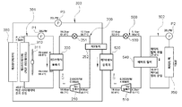
- FIG. 1 is a block diagram showing a thermal management system according to an embodiment of the present invention.
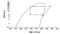
- FIGS. 2 and 3 are diagrams and PH diagrams showing operation simulation results of a conventional heat exchange system using one refrigerant circulation system.
- FIGS. 4 and 5 are diagrams and PH diagrams showing operation simulation results of a thermal management system according to an embodiment of the present invention.
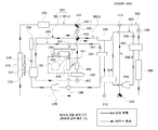
- FIG. 6 is a block diagram showing an operating state in a cooling mode dedicated to a battery of a heat management system according to another embodiment of the present invention.
- FIG. 7 is a configuration diagram showing an operating state in the maximum cooling mode of the heat management system according to another embodiment of the present invention.
- FIG. 8 is a configuration diagram showing an operating state in a mild cooling mode of a heat management system according to another embodiment of the present invention.
- FIG. 9 is a block diagram showing an operating state in the maximum heating mode of the heat management system according to another embodiment of the present invention.
- FIG. 10 is a block diagram showing an operating state in a mild heating mode of a heat management system according to another embodiment of the present invention.
- FIG. 11 is a configuration diagram showing an operating state in the dehumidification heating mode of the heat management system according to another embodiment of the present invention.
- FIG. 12 is a configuration diagram showing an operating state in the battery heating mode of the thermal management system according to another embodiment of the present invention.
- FIG. 1 is a block diagram showing a thermal management system according to an embodiment of the present invention.
- the thermal management system of the present invention may be largely composed of a refrigerant circulation line for cooling a room by circulating refrigerant and a cooling water circulation line for cooling components by circulating coolant.
- the refrigerant circulation line may be composed of a primary refrigerant circulation system 200 for circulating the first refrigerant and a secondary refrigerant circulation system 500 for circulating the second refrigerant.
- the cooling water circulation line is the first cooling line 301 for cooling the first refrigerant and the cooling water is circulated, and the cooling water is circulated and cooled by heat exchange with the second refrigerant, and the second cooling line for cooling the battery 350 using the cooling water 302, and a third cooling line 303 for mutually exchanging the first refrigerant and the second refrigerant using cooling water as a medium.
- the first cooling line 301 may include a first radiator 310, a cooling water pump P1 and a first water cooling condenser 220.
- the first radiator 310 is a heat exchanger that cools cooling water circulated along the first cooling line 301, and the first radiator 310 can be cooled by air cooling by a cooling fan 311 provided on one side thereof. have.
- the cooling water pump P1 is a means for feeding the cooling water to circulate the cooling water along the first cooling line 301.
- the cooling water pump (P1) is installed on the cooling water line between the first radiator 310 and the first water-cooled condenser 220, the cooling water cooled in the first radiator 310 by the operation of the cooling water pump (P1) It may be supplied to the first water-cooled condenser 220.
- the first water-cooled condenser 220 is a heat exchanger for exchanging heat between the cooling water flowing along the first cooling line 301 and the first refrigerant flowing along the primary refrigerant circulation system 200.
- the primary refrigerant circulation system 200 may include a first compressor 210, a first water-cooled condenser 220, a third expansion valve 251 and a first chiller 252.
- the primary refrigerant circulation system 200 may further include a separate expansion valve and an evaporator branched in parallel in the refrigerant loop to cool the vehicle interior, and in some cases utilize the first chiller 252 as an evaporator. It might be.
- the first compressor 210 may be an electric compressor driven by being supplied with electric power, and serves to suck and compress the first refrigerant and discharge it toward the first water-cooled condenser 220.
- the first water-cooled condenser 220 serves to heat the first refrigerant discharged from the first compressor 210 with cooling water flowing along the first cooling line 301 to condense it into a liquid refrigerant and send it to the third expansion valve 251 Do it.
- the third expansion valve 251 may serve to throttle or bypass the refrigerant or to block the flow of the refrigerant, and may be disposed behind the first water-cooled condenser 220 in the flow direction of the refrigerant.
- the first chiller 252 is disposed at the rear of the third expansion valve 251 in the flow direction of the refrigerant, and heat-exchanged with the cooling water to cool the cooling water flowing along the third cooling line 303.
- the third cooling line 303 may include a second radiator 380, a cooling water pump P3, a first chiller 252, and a second water cooling condenser 520.
- the second radiator 380 is a heat exchanger that cools the cooling water circulated along the third cooling line 303, and the second radiator 380 can be disposed side by side in close proximity to the first radiator 310, and is cooled. It can be cooled by air cooling by the fan 311.
- the cooling water pump P3 is a means for feeding the cooling water to circulate the cooling water along the third cooling line 303.
- the cooling water pump (P3) is installed on the cooling water line between the second radiator 380 and the first chiller 252, the cooling water cooled in the second radiator 380 by the operation of the cooling water pump (P3) is It can be supplied to one chiller 252.
- the first chiller 252 cools the cooling water flowing along the third cooling line 303 as described above, and the cooled cooling water is supplied to the second water cooling condenser 520 and passes through the second water cooling condenser 520.
- the second refrigerant can be cooled.
- the second water-cooled condenser 520 is a heat exchanger for exchanging heat between the coolant flowing along the third cooling line 303 and the second refrigerant flowing along the secondary refrigerant circulation system 500.
- the second water-cooled condenser 520 exchanges the second refrigerant discharged from the second compressor 510 with the cooling water flowing along the third cooling line 303 to condense it into a liquid refrigerant and send it to the fourth expansion valve 251. Plays a role.
- the secondary refrigerant circulation system 500 may include a second compressor 510, a second water-cooled condenser 520, a fourth expansion valve 530, and a battery chiller 540.
- the second compressor 510 may be an electric compressor driven by being supplied with power, and serves to suck and compress the second refrigerant and discharge it toward the second water-cooled condenser 520.
- the second water-cooled condenser 520 exchanges the second refrigerant discharged from the second compressor 510 with the cooling water flowing along the third cooling line 303 to condense the liquid refrigerant and send it to the fourth expansion valve 530 Do it.
- the fourth expansion valve 530 may serve to throttle or bypass the refrigerant or to block the flow of the refrigerant, and may be disposed behind the second water-cooled condenser 520 in the flow direction of the refrigerant.
- the battery chiller 540 is disposed at the rear of the fourth expansion valve 530 in the flow direction of the refrigerant, and heat-exchanged with the cooling water to cool the cooling water flowing along the second cooling line 302.
- the second cooling line 302 may include a battery chiller 540, a cooling water pump P2 and a battery 350.
- the battery chiller 540 is a heat exchanger that heats the second refrigerant flowing along the secondary refrigerant circulation system 500 and the cooling water flowing along the second cooling line 302.
- the cooling water pump P2 is a means for feeding the cooling water to circulate the cooling water along the second cooling line 302.
- the cooling water pump (P2) is installed on the cooling water line between the battery chiller 540 and the battery 350, the cooling water cooled in the battery chiller 540 by the operation of the cooling water pump (P2) to the battery 350 It can be supplied to cool the battery 350.
- the cooling water flowing along the first cooling line 301 passes through the first radiator 310 and is cooled, then cools the first refrigerant flowing along the primary refrigerant circulation system 200 in the first water-cooled condenser 220 and ,
- the first refrigerant flowing along the primary refrigerant circulation system 200 cools the cooling water flowing along the third cooling line 303 in the first chiller 252, and the cooling water flowing along the third cooling line 303
- the second refrigerant flowing along the secondary refrigerant circulation system 500 is second in the battery chiller 540.
- the cooling water flowing along the cooling line 302 is cooled, and the second cooling line 302 cools the battery 350 using the cooled cooling water.
- the primary refrigerant circulation system 200 and the secondary refrigerant circulation system 500 are respectively provided as two independent refrigerant systems, each provided with a compressor, and circulated along the closed loop primary refrigerant circulation system 200
- the first refrigerant and the second refrigerant circulated along the closed loop secondary refrigerant circulation system 500 may be heat-exchanged using the cooling water circulated along the third cooling line 303 as a medium.
- the pressure of the refrigerant is relatively low in the secondary refrigerant circulation system 500 compared to the primary refrigerant circulation system 200, so that the compression efficiency of the compressor is improved and the maximum performance can be achieved.
- the present invention is configured to cool the battery using two relatively small compressors, such as the present invention, compared to cooling the battery using one relatively large compressor, which is sufficient to rapidly charge the battery of an electric vehicle. Cooling performance can be secured and the durability of the compressor can be improved. In addition, noise and vibration are distributed by two compressors, so that noise and vibration can be reduced compared to using a compressor with a large capacity. In addition, since the present invention uses less power in the compressors than the one with a large capacity compressor, the efficiency of the system is high. In addition, since it is stopped when the battery of the electric vehicle is rapidly charged, the amount of air for heat dissipation in the radiator is insufficient. In the present invention, the cooling performance can be satisfied with a small amount of air.
- the rotation speed (RPM) of the first compressor 210 of the primary refrigerant circulation system 200 is lower than the rotation speed (RPM) of the second compressor 510 of the secondary refrigerant circulation system 500.
- the first compressor 210 and the second compressor 510 may be driven at different rotation speeds that are not the same.
- the noise and vibration of the two compressors do not overlap, so that the overall noise and vibration can be further reduced.
- first chiller 252 of the primary refrigerant circulation system 200 and the second water-cooled condenser 520 of the secondary refrigerant circulation system 500 are spaced apart from each other, so that the first chiller 252 and the second water-cooling type The thermal shock between the condensers 520 can be reduced.
- any component may not be provided between the first chiller 252 and the second water-cooled condenser 520 on the cooling water line of the third cooling line 303.
- the first chiller 252 and the second water-cooled condenser 520 are integrally configured to exchange heat between the first refrigerant and the second refrigerant using a cooling water medium that is a heat exchange medium different from the first refrigerant and the second refrigerant. It might be.
- FIGS. 4 and 5 show the operation simulation results of the thermal management system according to an embodiment of the present invention. It is the figure and the PH diagram.
- the power consumption of the compressor is 6.69 kW and the rotation speed is high at 10,000 RPM
- the power consumption of the compressor is relatively small, 0.86 kW and 4.69 kW, respectively, and the rotation speed is relatively low, respectively, 2,000 RPM and 8,000PRM. Therefore, it can be seen that, in the present invention, a compressor having a smaller capacity can be used in the present invention, and the sum of the power consumption of the two compressors of the present invention is smaller than that of the conventional one compressor, thereby increasing the efficiency of the overall system.
- the compressors are operated at different rotation speeds, thereby reducing noise and vibration.
- the pressure on the outlet side of the compressor is relatively high, whereas in the present invention, the pressure on the outlet side of the compressor is formed relatively low to compress the refrigerant. The efficiency of the system can be improved by reducing the power consumption of the required compressor.
- FIG. 6 is a block diagram showing a thermal management system according to another embodiment of the present invention.
- the thermal management system of the present invention includes a primary refrigerant circulation system 200 in which the first refrigerant is circulated to cool the room and cools the cooling water, and a secondary refrigerant circulation in which the second refrigerant is circulated to cool the cooling water
- the system 500 may include a cooling water circulation line 300 in which cooling water is circulated to heat the room and cool parts.
- the cooling water circulation line 300 includes a first cooling line 301 including a heating line 301-1 for indoor heating and a cooling line 301-2 for cooling the electric components 460 or the battery 350. ), and a second cooling line 302 for cooling the battery 350.
- the primary refrigerant circulation system 200 includes a first compressor 210, a first water-cooled condenser 220, a first expansion valve 225, an air-cooled condenser 230, a refrigerant branch 241, and a second expansion valve ( 240), an evaporator 242, a refrigerant heat exchanger 233, an accumulator 260, a third expansion valve 251 and a first chiller 252.
- the first compressor 210 may be an electric compressor driven by being supplied with electric power, and serves to suck and compress refrigerant to discharge it toward the first water-cooled condenser 220.
- the first water-cooled condenser 220 serves to heat the refrigerant discharged from the first compressor 210 with cooling water and condense it into a liquid refrigerant to send it to the first expansion valve 225.
- the first expansion valve 225 may serve to throttle or bypass the refrigerant, or to block the flow of the refrigerant, and may be disposed behind the first water-cooled condenser 220 in the flow direction of the refrigerant.
- the air-cooled condenser 230 functions as a condenser or an evaporator, and the function of the air-cooled condenser 230 may be changed according to the role of the first expansion valve 225. That is, when the primary refrigerant circulation system 200 is used as an air conditioner loop, the first expansion valve 225 is completely opened to pass the refrigerant, and the air-cooled condenser 230 serves as a condenser together with the first water-cooled condenser 220 When the refrigerant primary refrigerant circulation system 200 is used as a heat pump loop, the first expansion valve 225 throttles the refrigerant, and the air-cooled condenser 230 serves as an evaporator. In addition, the air-cooled condenser 230 may be cooled or heated air-cooled by external air.
- the refrigerant branch 241 may be formed on the rear side of the air-cooled condenser 230 in the flow direction of the refrigerant, and branched into two lines in the refrigerant branch 241, one line is connected to the evaporator 242 The other line may be configured to be connected to the first chiller 252.
- the second expansion valve 240 and the third expansion valve 251 may serve to throttle or pass the refrigerant or to block the flow of the refrigerant.
- the second expansion valve 240 and the third expansion valve 251 may be configured in parallel. That is, the refrigerant line is branched from the cold distribution branch 241 into two lines, a second expansion valve 240 is disposed on one of the two branched refrigerant lines, and a third expansion is performed on the other refrigerant line.
- the valve 251 may be disposed. At this time, the second expansion valve 240 may be disposed in front of the evaporator 242, and the third expansion valve 251 may be disposed in front of the first chiller 252.
- the evaporator 242 is disposed at the rear of the second expansion valve 240 in the flow direction of the refrigerant, and is provided inside the air conditioner 150 of the vehicle, and the air flowing by the blower 152 of the air conditioner is evaporator 242 ) And cooled to be supplied to the vehicle interior and used for cooling the vehicle interior.
- the refrigerant heat exchanger 233 serves to improve cooling performance by exchanging heat between the refrigerant flowing into the second expansion valve 240 and the refrigerant discharged from the evaporator 242.
- the refrigerant heat exchanger 233 passes through the refrigerant line flowing into the evaporator 242 connecting the refrigerant branch 241 and the second expansion valve 240, and the evaporator 242 and the accumulator ( In the evaporator 242 connecting the 260, the discharge-side refrigerant line through which the refrigerant is discharged passes, and heat exchange between refrigerants passing through the inlet-side refrigerant line and the discharge-side refrigerant line may occur.
- the refrigerant may be further cooled before being introduced into the second expansion valve 240 by the refrigerant heat exchanger 233, and the cooling performance through the evaporator 242 may be improved and the efficiency of the cooling system may be improved.
- the refrigerant heat exchanger 233 is connected to the air-cooled condenser 230 and the chiller 252 in parallel. That is, the refrigerant heat exchanger 233 is not disposed in series in the refrigerant line between the air-cooled condenser 230 and the chiller 252, but is disposed adjacent to the evaporator 242, so that the refrigerant heat exchanger 233 and the evaporator 242 are It can be arranged in series and connected. If, when the refrigerant heat exchanger 233 is arranged in series between the air-cooled condenser 230 and the chiller 252, the heating performance may be reduced by acting as a low pressure side pressure drop in the heating mode.
- the cooling performance as well as the heating performance are increased, which is a refrigerant heat exchanger 233 between the condensers 220 and 230 and the chiller 252 in the refrigerant flow in the heating mode. Because there is no.
- the first chiller 252 is disposed at the rear of the third expansion valve 251 in the flow direction of the refrigerant, and the cooling water may be cooled by exchanging heat with the cooling water.
- the second expansion valve 240 and the evaporator 242 form one set
- the third expansion valve 251 and the first chiller 252 form another set
- the two sets are configured in parallel on the refrigerant line.
- a refrigerant line may be formed as a single refrigerant line by condensing refrigerant lines at the rear side of the evaporator 242 and the chiller 252 in the refrigerant flow direction.
- the accumulator 260 may separate the liquid refrigerant and the gaseous refrigerant among refrigerants and supply only the gaseous refrigerant to the first compressor 210.
- the accumulator 260 is disposed and connected at a point where the rear side of the evaporator 242 and the refrigerant line at the rear side of the first chiller 252 are joined, and the accumulator 260 is the first compressor 210 in the refrigerant flow direction. ).
- the heating line 301-1 includes a first water-cooled condenser 220, a first cooling water pump 450, a cooling water heater 430, a heater core 440, and a first direction switching valve ( 410).
- the first water-cooled condenser 220 may exchange heat with each other while the refrigerant and the cooling water pass.
- the first cooling water pump 450 is a means for pushing the cooling water to circulate the cooling water along the heating line 301-1, and the first cooling water pump 450 is a rear of the first water cooling type condenser 220 in the flow direction of the cooling water. It can be disposed on and installed on the cooling water line.
- the cooling water heater 430 is a device for heating the cooling water, and may be disposed and connected to the rear of the first cooling water pump 450 and the front of the heater core 440 in the flow direction of the cooling water.
- the cooling water heater 430 may be operated when the temperature of the cooling water is below a specific temperature, and may be variously formed, such as an induction heater, a seed heater, a PTC heater, or a film heater capable of generating heat using electric power.
- the heater core 440 may be disposed in the air conditioning unit 150 of the vehicle, and the air flowing by the blower 152 is heated through the heater core 440 and supplied to the vehicle interior to be used for indoor heating of the vehicle. Can be.
- the heater core 440 may be disposed and connected to the rear of the cooling water heater 430 in the flow direction of the cooling water.
- the air conditioning device 150 is provided with a blower 152 on one side to blow air, and a temperature control door 151 may be installed inside the air conditioning device 150.
- the evaporator 242 and the heater core 440 disposed in the air conditioning apparatus allow air discharged from the blower 152 to flow into the room after only the evaporator 242 according to the operation of the temperature control door 151, After passing through the evaporator 242, the heater core 440 may be disposed and configured to be introduced into the room.
- the first direction switching valve 410 may be installed between the heater core 440 and the first water-cooled condenser 220, and a heating line 301-1 and a cooling line 301-2 to be described later. It can be configured to selectively connect or disconnect. More specifically, the first direction switching valve 410 is installed on the heating line 301-1 so that two cooling water line pipes are connected to the first direction switching valve 410, and one side of the cooling line 301-2. One first connection line 302-1 branched from is connected to the first direction switching valve 410, and one second connection line 302-2 branched from the other side of the cooling line 302 is removed. It may be connected to the one-way switching valve 410.
- the first direction switching valve 410 in the first direction switching valve 410, four cooling water lines are connected to meet each other, and the first direction switching valve 410 is a four-way direction switching in which four cooling water lines are connected to each other or can control a blocked state. It can be a valve.
- the cooling line 301-2 includes a first radiator 310, a reservoir tank 370, a second direction switching valve 320, a second cooling water pump 420, and a first direction switching.
- a valve 410, an electric component 460, and a second coolant joint 312 may be included.
- the first radiator 310 is a heat exchanger that cools the cooling water exchanged with the electric component 460 or the battery 350, and the first radiator 310 may be cooled by air cooling by a cooling fan 311.
- the reservoir tank 370 may serve to store cooling water and replenish insufficient cooling water on the cooling water line, and the reservoir tank 370 includes the second cooling water pump 420 and the third cooling water pump 340 in the flow direction of the cooling water. ) It can be installed on the front coolant line.
- the second direction switching valve 320 is installed on the cooling line 301-2, and two cooling water pipes are connected to the second direction switching valve 320, and the heating line 301-1 and the cooling line 301- 2)
- the first direction switching valve 410 and the second direction switching valve 320 may be connected to the first connection line 302-1 so that the connection is made. That is, the second direction switching valve 320 is connected so that the three cooling water lines meet, and the second direction switching valve 320 is three-way direction switching that can control the state where the three cooling water lines are connected to each other or blocked. It can be a valve.
- the second cooling water pump 420 is a means for feeding the cooling water so that the cooling water circulates along the cooling line 302. And the second cooling water pump 420 is installed on the first connection line 302-1 between the first direction switching valve 410 and the second direction switching valve 320, the second cooling water pump 420 Cooling water may flow from the second direction switching valve 320 toward the first direction switching valve 410 by operation.
- the first direction switching valve 410 is as described in the above-described heating line 301-1.
- the electric component 460 is disposed on the second connection line 302-2 connecting the first direction switching valve 410 and the second coolant joint 312, so that the electric component 460 is cooled by the coolant.
- the electric component 460 may be a driving motor, an inverter, an On Board Charger (OBC), or the like.
- the second coolant joint 312 may be installed at a point where the rear end of the second connection line 302-2 meets the cooling line 301-2, and three coolant lines meet at the second coolant joint 312. Is connected. That is, the second coolant joint 312 is installed so that both sides are connected on the cooling line 301-2, and the second connection line 302-2 may be connected to the upper side.
- the first chiller 252 is as described in the above-described heating line 301-1.
- the secondary refrigerant circulation system 500 may include a second compressor 510, a second water-cooled condenser 520, a fourth expansion valve 530, and a battery chiller 540.
- the second compressor 510 may be an electric compressor driven by being supplied with power, and serves to suck and compress the second refrigerant and discharge it toward the second water-cooled condenser 520.
- the second water-cooled condenser 520 heat exchanges the second refrigerant discharged from the second compressor 510 with the cooling water flowing along the second connection line 302-2 to condense it into a liquid refrigerant to the fourth expansion valve 530. It serves to send.
- the fourth expansion valve 530 may serve to throttle or bypass the refrigerant or to block the flow of the refrigerant, and may be disposed behind the second water-cooled condenser 520 in the flow direction of the refrigerant.
- the battery chiller 540 is disposed at the rear of the fourth expansion valve 530 in the flow direction of the refrigerant, and heat-exchanged with the cooling water to cool the cooling water flowing along the second cooling line 302.
- the second cooling line 301-2 may include a third cooling water pump 340, a battery chiller 540, a battery 350, a third direction switching valve 330 and a first cooling water joint 313. Can.
- the third cooling water pump 340 is a means for feeding the cooling water to circulate the cooling water along the second cooling line 302. And the third cooling water pump 340 is installed on the cooling water line in front of the battery chiller 540 in the flow direction of the cooling water, the cooling water cooled in the battery chiller 540 by the operation of the third cooling water pump 340 is a battery It is supplied toward the 350 to cool the battery 350.
- the battery chiller 540 may be installed on a cooling water line between the third cooling water pump 340 and the battery chiller 540 to cool the cooling water flowing along the second cooling line 302.
- the third direction switching valve 330 is installed on the cooling water line between the battery 350 and the second coolant joint 312, and two cooling water pipes are connected to the third direction switching valve 330, and the third direction
- the third connection line 302-3 may be connected to the upper side of the switching valve 330 such that the battery 350 and the third connection line 302-3 are connected in parallel.
- the second direction switching valve 320 may be a three-way direction switching valve capable of adjusting a state in which three coolant lines are connected to each other or blocked.
- the first coolant joint 313 is installed in the coolant line at the rear of the second direction switching valve 320 in the flow direction of the coolant, and the first coolant joint 313 is connected so that the three coolant lines meet. That is, the first coolant joint 313 is installed so that both sides are connected to the cooling line 301-2 and the second cooling line 302, and a third connection line 302-3 may be connected to the lower side.
- the third connection line 302-3 is a part of the second cooling line 302.
- the electric component 460, the first chiller 252, and the second water-cooled condenser 520 may be arranged to be separated from each other in the flow direction of the cooling water on the second connection line 302-2.
- FIG. 6 is a block diagram showing an operating state in a cooling mode dedicated to a battery of a heat management system according to another embodiment of the present invention.
- the first compressor 210 operates to discharge high-temperature, high-pressure refrigerant from the first compressor 210.
- the refrigerant discharged from the first compressor 210 is cooled by heat exchange with cooling water in the first water-cooled condenser 220.
- the refrigerant cooled in the first water-cooled condenser 220 passes through the first expansion valve 225 in a completely open state and flows into the air-cooled condenser 230, and the refrigerant is exchanged with external air in the air-cooled condenser 230 Cooled.
- the first water-cooled condenser 220 and the air-cooled condenser 230 both serve as condensers to condense the refrigerant.
- the condensed refrigerant passes through the refrigerant branch 241 and passes through the third expansion valve 251, it is throttled to expand the refrigerant, and then the expanded refrigerant is exchanged with the cooling water while passing through the first chiller 252 to cool the refrigerant.
- the cooling water is cooled.
- the refrigerant evaporated through the first chiller 252 flows back through the accumulator 260 to the first compressor 210.
- the second expansion valve 240 is blocked and refrigerant may not flow to the evaporator 242.
- the refrigerant is circulated while repeating the above process.
- the second compressor 510 operates to discharge high-temperature, high-pressure refrigerant from the second compressor 510.
- the refrigerant discharged from the second compressor 510 is cooled by heat exchange with cooling water in the second water-cooled condenser 520.
- the refrigerant cooled in the second water-cooled condenser 520 passes through the fourth expansion valve 540 and is throttled to expand the refrigerant, and then the expanded refrigerant passes through the battery chiller 540 to the second cooling line 302. Heat exchange with the circulating cooling water to cool the cooling water.
- the refrigerant that has passed through the battery chiller 540 flows back into the second compressor 510 and is circulated.
- the cooling water of the first cooling line 301 among the cooling water circulation lines 300 is circulated by the operation of the first cooling water pump 450 and the second cooling water pump 420.
- the refrigerant passing through the first water-cooled condenser 220, the electric components 460 and the refrigerant passing through the second water-cooled condenser 520 may be cooled by the cooling water, and the heated cooling water is transferred from the first radiator 310.
- the cooling fan 311 it may be cooled by heat exchange with external air.
- the cooling water after passing through the electric component 460 may be cooled while passing through the first chiller 252.
- the first direction switching valve 410 and the second direction switching valve 320 may be adjusted in a direction connecting the heating line 301-1 and the cooling line 301-2. More specifically, the first direction switching valve 410 may be connected to the upper side and the left side, and the cooling water may flow, and the lower side and the right side may be connected to each other, thereby allowing the cooling water to flow. In addition, the second direction switching valve 320 may be connected to the left side and the bottom side so that cooling water flows and the right side is blocked. In addition, the third direction switching valve 330 may have an upper side and a right side connected to each other and a left side may be blocked.
- the cooling water of the first cooling line 301 is from the first radiator 310 to the reservoir tank 370, the second direction switching valve 320, the second cooling water pump 420, the first direction switching valve 410, The first water-cooled condenser 220, the first cooling water pump 450, the cooling water heater 430, the heater core 440, the first direction switching valve 410, the electric components 460, the first chiller 252,
- the cycle in which the second water-cooled condenser 520 and the second coolant joint 312 are sequentially introduced into the first radiator 310 and circulated is repeated.
- the cooling water does not flow from the second direction switching valve 320 to the first coolant joint 313 by the second direction switching valve 320, and the third direction switching valve by the third direction switching valve 330 Coolant may not flow from 330 to the second coolant joint 312.
- the cooling water of the second cooling line 302 is circulated by the operation of the third cooling water pump 340, the battery chiller 540, the battery 350, the third direction switching valve from the third cooling water pump 340 330, the cycle through which the first coolant joint 313 flows through in turn and flows into the third coolant pump 340 is repeated. That is, the cooling line is formed in a separate closed loop in which cooling water is circulated by the second direction switching valve 320 and the third direction switching valve 330, so that the battery 350 may be separately cooled.
- the battery-only cooling mode may be operated when fast charging of the battery is required without cooling the room.
- the first compressor 210 may be rotated at 2,000 rpm and the second compressor 510 may be rotated at 8,000 rpm.
- FIG. 7 is a configuration diagram showing an operating state in the maximum cooling mode of the heat management system according to another embodiment of the present invention.
- the first compressor 210 operates to discharge high-temperature, high-pressure refrigerant from the first compressor 210.
- the refrigerant discharged from the first compressor 210 is cooled by heat exchange with cooling water in the first water-cooled condenser 220.
- the refrigerant cooled in the first water-cooled condenser 220 passes through the first expansion valve 225 in a completely open state and flows into the air-cooled condenser 230, and the refrigerant is exchanged with external air in the air-cooled condenser 230 Cooled.
- the first water-cooled condenser 220 and the air-cooled condenser 230 both serve as condensers to condense the refrigerant.
- the condensed refrigerant is then branched from the refrigerant branch 241, and a part of the refrigerant passes through the refrigerant heat exchanger 233, is throttled while passing through the second expansion valve 240, and the refrigerant expands. While passing through the evaporator 242, heat is exchanged with the air blown by the blower 152 of the air conditioning apparatus 150 to cool the air as the refrigerant evaporates, and the cooled air is supplied to the vehicle interior to provide indoor cooling.
- the refrigerant evaporated from the evaporator 242 passes through the refrigerant heat exchanger 233 and heat exchanges with the refrigerant before flowing into the second expansion valve 240 and then flows back through the accumulator 260 to the first compressor 210 again.
- the remainder of the refrigerant branched from the refrigerant branch 241 is throttled while passing through the third expansion valve 251 to expand the refrigerant, and the expanded refrigerant is then exchanged with cooling water while passing through the first chiller 252.
- the cooling water is cooled.
- the refrigerant evaporated through the first chiller 252 flows back through the accumulator 260 to the first compressor 210.
- the refrigerant passing through the evaporator 242 and the refrigerant passing through the first chiller 252 are joined by the accumulator 260 and introduced into the first compressor 210, the refrigerant is repeated while repeating the above process. Circulates.
- the second compressor 510 operates to discharge high-temperature, high-pressure refrigerant from the second compressor 510.
- the refrigerant discharged from the second compressor 510 is cooled by heat exchange with cooling water in the second water-cooled condenser 520.
- the refrigerant cooled in the second water-cooled condenser 520 passes through the fourth expansion valve 540 and is throttled to expand the refrigerant, and then the expanded refrigerant passes through the battery chiller 540 to the second cooling line 302. Heat exchange with the circulating cooling water to cool the cooling water.
- the refrigerant that has passed through the battery chiller 540 flows back into the second compressor 510 and is circulated.
- the cooling water of the first cooling line 301 of the cooling water circulation line 300 is circulated by the operation of the first cooling water pump 450, the second cooling water pump 420 and the third cooling water pump 340.
- the refrigerant passing through the first water-cooled condenser 220, the electric components 460 and the refrigerant passing through the second water-cooled condenser 520 may be cooled by the cooling water, and the heated cooling water is transferred from the first radiator 310.
- the cooling fan 311 it may be cooled by heat exchange with external air.
- the cooling water is cooled while passing through the first chiller 252, and the cooling water cooled by the first chiller 252 is second cooled while passing through the second water-cooled condenser 520.
- the refrigerant circulated along line 302 is cooled.
- the first direction switching valve 410 and the second direction switching valve 320 may be adjusted in a direction connecting the heating line 301-1 and the cooling line 301-2. More specifically, the first direction switching valve 410 may be connected to the upper side and the left side, and the cooling water may flow, and the lower side and the right side may be connected to each other, thereby allowing the cooling water to flow. In addition, the second direction switching valve 320 may be connected to the left side and the bottom side so that cooling water flows and the right side is blocked. In addition, the third direction switching valve 330 may have an upper side and a right side connected to each other and a left side may be blocked.
- the cooling water of the first cooling line 301 is from the first radiator 310 to the reservoir tank 370, the second direction switching valve 320, the second cooling water pump 420, the first direction switching valve 410, The first water-cooled condenser 220, the first cooling water pump 450, the cooling water heater 430, the heater core 440, the first direction switching valve 410, the electric components 460, the first chiller 252,
- the cycle in which the second water-cooled condenser 520 and the second coolant joint 312 are sequentially introduced into the first radiator 310 and circulated is repeated.
- the cooling water does not flow from the second direction switching valve 320 to the first coolant joint 313 by the second direction switching valve 320, and the third direction switching valve by the third direction switching valve 330 Coolant may not flow from 330 to the second coolant joint 312.
- the cooling water of the second cooling line 302 is sequentially from the third cooling water pump 340 to the battery chiller 540, the battery 350, the third direction switching valve 330, and the first cooling water joint 313. After that, the cycle of being introduced into the third cooling water pump 340 and circulated is repeated. That is, the cooling line is formed in a separate closed loop in which cooling water is circulated by the second direction switching valve 320 and the third direction switching valve 330, so that the battery 350 may be separately cooled.
- the maximum cooling mode may be operated when the temperature of the external air is in the range of 30 degrees to 45 degrees Celsius, wherein the first compressor 210 and the second compressor 510 may be rotated at the maximum number of revolutions, respectively.
- the third expansion valve 251 may be blocked so that refrigerant does not flow toward the first chiller 252.
- the third cooling water pump 340 may not operate, and the secondary refrigerant circulation system 500 may not operate.
- FIG. 8 is a configuration diagram showing an operating state in a mild cooling mode of a heat management system according to another embodiment of the present invention.
- the first compressor 210 operates to discharge high-temperature and high-pressure refrigerant from the first compressor 210.
- the refrigerant discharged from the first compressor 210 is cooled by heat exchange with cooling water in the first water-cooled condenser 220.
- the refrigerant cooled in the first water-cooled condenser 220 passes through the first expansion valve 225 in a completely open state and flows into the air-cooled condenser 230, and the refrigerant is exchanged with external air in the air-cooled condenser 230 Cooled.
- the first water-cooled condenser 220 and the air-cooled condenser 230 both serve as condensers to condense the refrigerant.
- the condensed refrigerant is then branched from the refrigerant branch 241, and a part of the refrigerant passes through the refrigerant heat exchanger 233, is throttled while passing through the second expansion valve 240, and the refrigerant expands. While passing through the evaporator 242, heat is exchanged with the air blown by the blower 152 of the air conditioning apparatus 150 to cool the air as the refrigerant evaporates, and the cooled air is supplied to the vehicle interior to provide indoor cooling.
- the refrigerant evaporated from the evaporator 242 passes through the refrigerant heat exchanger 233 and heat exchanges with the refrigerant before flowing into the second expansion valve 240 and then flows back through the accumulator 260 to the first compressor 210 again.
- the third expansion valve 251 is blocked so that the refrigerant may not flow to the first chiller 252.
- the refrigerant that has passed through the evaporator 242 flows into the first compressor 210 through the accumulator 260, and the refrigerant is circulated while repeating the above-described process.
- the cooling water of the cooling water circulation line 300 is circulated by the operation of the first cooling water pump 450, the second cooling water pump 420 and the third cooling water pump 340.
- the refrigerant passing through the first water-cooled condenser 220, the electric components 460 and the battery 350 may be cooled by the cooling water, and the heated cooling water operates the cooling fan 311 in the first radiator 310.
- the first direction switching valve 410 and the second direction switching valve 320 may be adjusted in a direction connecting the heating line 301-1 and the cooling line 301-2 of the first cooling line 301.
- the second direction switching valve 320 and the third direction switching valve 330 may be adjusted in a direction connecting the first cooling line 301 and the second cooling line 302. More specifically, the first direction switching valve 410 may be connected to the upper side and the left side, and the cooling water may flow, and the lower side and the right side may be connected to each other, thereby allowing the cooling water to flow. In addition, the second direction switching valve 320 may be connected to the left, lower, and right sides in the three directions, thereby allowing cooling water to flow therethrough. In addition, the third direction switching valve 330 may be connected to the left and right sides and the upper side may be blocked.
- the cycle through which the coolant joint 312 flows in turn and flows back into the first radiator 310 is repeated.
- cooling water flows to the right by the second direction switching valve 320, so that the first cooling water joint 313, the third cooling water pump 340, the battery chiller 540, the battery 350, and the third direction
- the cycle through which the circulating valve 330 and the second coolant joint 312 are introduced and flown into the first radiator 310 again is repeated.
- the coolant that has passed through the electric component 460 and the coolant that has passed through the battery 350 may be joined at the second coolant joint 312 and introduced into the first radiator 310.
- cooling water may not flow through the third connection line 302-3 by the third direction switching valve 330.
- the mild cooling mode can be operated when the temperature of the outside air is in the range of 15 to 25 degrees Celsius, and the battery can be cooled by the first radiator, so that the refrigerant is the primary refrigerant circulation system 200. Since the first chiller 252 does not circulate and the secondary refrigerant circulation system 500 may not operate, there is an advantage of reducing power consumed in driving the compressor.
- FIG. 9 is a block diagram showing an operating state in the maximum heating mode of the heat management system according to another embodiment of the present invention.
- the first compressor 210 operates to discharge high-temperature, high-pressure refrigerant from the first compressor 210.
- the refrigerant discharged from the first compressor 210 is cooled by heat exchange with cooling water in the first water-cooled condenser 220.
- the refrigerant cooled in the first water-cooled condenser 220 is throttled while passing through the first expansion valve 225 to expand the refrigerant, and the expanded refrigerant heats up with external air while passing through the air-cooled condenser 230 to evaporate the refrigerant. As it absorbs heat from outside air.
- the refrigerant passes through the refrigerant branch 241 and passes through the third expansion valve 251 in a fully opened state, and then flows into the first chiller 252, and in the first chiller 252, the refrigerant and the coolant exchange heat. Can be heated.
- the refrigerant that has passed through the first chiller 252 then flows back through the accumulator 260 to the first compressor 210.
- the second expansion valve 240 is blocked and refrigerant may not flow to the evaporator 242.
- the refrigerant is circulated while repeating the above process.
- the second compressor 510 operates to discharge high-temperature, high-pressure refrigerant from the second compressor 510.
- the refrigerant discharged from the second compressor 510 is cooled by heat exchange with cooling water in the second water-cooled condenser 520.
- the refrigerant cooled in the second water-cooled condenser 520 passes through the fourth expansion valve 540 in a fully opened state and flows into the battery chiller 540, and then the refrigerant that has passed through the battery chiller 540 is removed again. 2
- the process of being introduced into the compressor 510 and circulated may be repeated.
- the second compressor 510 may not operate in the secondary refrigerant circulation system 500, so that the refrigerant may not flow.
- the cooling water in the cooling water circulation line 300 is circulated by the operation of the first cooling water pump 450 and the second cooling water pump 420. And the cooling water is heated while passing through the first water-cooled condenser 220, is heated by the cooling water heater 430, may be heated by the waste heat of the electric component 460, and is cooled while passing through the first chiller 252. Can.
- the first direction switching valve 410, the second direction switching valve 320 and the third direction switching valve 330 are the heating line 301-1 and the cooling line 301- of the first cooling line 301. 2) is adjusted in the direction of separating, it can be adjusted in the direction of connecting the first cooling line 301 and the second cooling line 302.
- the first direction switching valve 410 may be connected to the upper side and the right side, so that the cooling water flows, and the lower side and the left side may be connected to each other, thereby allowing the cooling water to flow.
- the second direction switching valve 320 may be connected to the right side and the bottom side, so that coolant flows and the left side may be blocked.
- the third direction switching valve 330 may be connected to the upper side and the left side and the right side may be blocked.
- the cooling water of the heating line 301-1 is in turn the first cooling water pump 450, the cooling water heater 430, the heater core 440, the first direction switching valve 410 and the first water cooling type condenser 220. After passing through the first cooling water pump 450 again, the cycle is repeated. And the cooling water of the cooling line 301-2 separated from the heating line 301-1 is from the second cooling water pump 420 to the first direction switching valve 410, the electric components 460, and the first chiller 252.
- the second water cooled condenser 520, the second coolant joint 312, the third direction change valve 330, the first coolant joint 313, and the second direction change valve 320 in turn, and then again through the second coolant
- the cycle of being introduced into the pump 420 and circulated is repeated.
- the cooling water may not flow from the second direction switching valve 320 to the second coolant joint 312 through the first radiator 310 by the second direction switching valve 320, and the third direction switching valve Cooling water may not flow from the third direction switching valve 330 to the first cooling water joint 313 through the battery 350, the battery chiller 540, and the third cooling water pump 340 by 330.
- the cooling water passes through the heater core 440 and heats air by being heat-exchanged with air blown by the blower 152 of the air conditioner 150, and the heated air is supplied to the vehicle interior to provide indoor heating.
- the heat management system according to the present invention is configured separately from the heating line 301-1, and may further include an air-heating heater that directly heats the air entering the room to heat the room. That is, an air-heated heater may be provided in close proximity to the heater core 440, and the air-heated heater is, for example, electrically operated and is formed of a low-voltage PTC heater having a relatively small heat generation capacity, thereby rapidly heating air. Thus, it is possible to increase the fast-acting effect of indoor heating.
- the maximum heating mode may be operated when the temperature of the external air is in the range of -20 degrees to -5 degrees Celsius, and controls the third direction switching valve 330 and the third cooling water pump 340 to control the battery 350 ) May be cooled.
- FIG. 10 is a block diagram showing an operating state in a mild heating mode of a heat management system according to another embodiment of the present invention.
- the primary refrigerant circulation system 200 and the secondary refrigerant circulation system 500 do not operate and the refrigerant is not circulated.
- the cooling water in the cooling water circulation line 300 is circulated by the operation of the first cooling water pump 450 and the second cooling water pump 420.
- the cooling water may be heated only by waste heat of the electric component 460.
- the first direction switching valve 410, the second direction switching valve 320 and the third direction switching valve 330 are the heating line 301-1 and the cooling line 301- of the first cooling line 301. 2) may be adjusted in a direction to connect, and may be adjusted in a direction to connect the first cooling line 301 and the second cooling line 302. More specifically, the first direction switching valve 410 may be connected to the upper side and the left side, and the cooling water may flow, and the lower side and the right side may be connected to each other, thereby allowing the cooling water to flow.
- the second direction switching valve 320 may be connected to the right side and the bottom side, so that coolant flows and the left side may be disconnected.
- the third direction switching valve 330 may be connected to the left side and the top side, and the right side may be blocked.
- the cooling water from the third direction switching valve 330 to the battery 350, the battery chiller 540, the third cooling water pump 340, and the first cooling water joint 313 by the third direction switching valve 330 May not flow, and cooling water may not flow from the second direction switching valve 320 to the second cooling water joint 312 by the second direction switching valve 320 through the first radiator 310.
- the heating demand is low, only the waste heat of the electric component 460 can be used to heat the cooling water and use it for indoor heating.
- the mild heating mode can be operated when the temperature of the outside air is in the range of 5 to 15 degrees Celsius.
- FIG. 11 is a block diagram showing the operating state in the dehumidification heating mode of the heat management system according to an embodiment of the present invention.
- the first compressor 210 operates to discharge high-temperature, high-pressure refrigerant from the first compressor 210.
- the refrigerant discharged from the first compressor 210 is cooled by heat exchange with cooling water in the first water-cooled condenser 220.
- the refrigerant cooled in the first water-cooled condenser 220 is throttled while passing through the first expansion valve 225, so that the refrigerant expands, and the expanded refrigerant passes through the air-cooled condenser 230 and branches off the branch 241 to coolant.
- a portion of the air passes through the refrigerant heat exchanger (233) and then bypasses the second expansion valve (240), after which the refrigerant passes through the evaporator (242) while air is blown by the blower (152) of the air conditioning device (150) While heat exchanged with, moisture in the air is removed. Then, the refrigerant that has passed through the evaporator 242 passes through the refrigerant heat exchanger 233 and flows back through the accumulator 260 to the first compressor 210.
- the remainder of the refrigerant branched from the refrigerant branching unit 241 bypasses the third expansion valve 240, and then the refrigerant passes through the first chiller 252 and then joins at the accumulator 260 to be the first compressor. After flowing into 210, the refrigerant is circulated while repeating the above-described process.
- the second compressor 510 operates to discharge high-temperature, high-pressure refrigerant from the second compressor 510.
- the refrigerant discharged from the second compressor 510 is cooled by heat exchange with cooling water in the second water-cooled condenser 520.
- the refrigerant cooled in the second water-cooled condenser 520 passes through the fourth expansion valve 540 in a fully opened state and flows into the battery chiller 540, and then the refrigerant that has passed through the battery chiller 540 is removed again. 2
- the process of being introduced into the compressor 510 and circulated may be repeated.
- the second compressor 510 may not operate in the secondary refrigerant circulation system 500, so that the refrigerant may not flow.
- the cooling water in the cooling water circulation line 300 is circulated by the operation of the first cooling water pump 450 and the second cooling water pump 420. And the cooling water is heated while passing through the first water-cooled condenser 220, is heated by the cooling water heater 430, may be heated by the waste heat of the electric component 460, and is cooled while passing through the first chiller 252. Can.
- the first direction switching valve 410, the second direction switching valve 320 and the third direction switching valve 330 are the heating line 301-1 and the cooling line 301- of the first cooling line 301. 2) is adjusted in the direction of separating, it can be adjusted in the direction of connecting the first cooling line 301 and the second cooling line 302.
- the first direction switching valve 410 may be connected to the upper side and the right side, so that the cooling water flows, and the lower side and the left side may be connected to each other, thereby allowing the cooling water to flow.
- the second direction switching valve 320 may be connected to the right side and the bottom side, so that coolant flows and the left side may be blocked.
- the third direction switching valve 330 may be connected to the upper side and the left side and the right side may be blocked.
- the cooling water of the heating line 301-1 is in turn the first cooling water pump 450, the cooling water heater 430, the heater core 440, the first direction switching valve 410 and the first water cooling type condenser 220. After passing through the first cooling water pump 450 again, the cycle is repeated. And the cooling water of the cooling line 301-2 separated from the heating line 301-1 is from the second cooling water pump 420 to the first direction switching valve 410, the electric components 460, and the first chiller 252.
- the second water cooled condenser 520, the second coolant joint 312, the third direction change valve 330, the first coolant joint 313, and the second direction change valve 320 in turn, and then again through the second coolant
- the cycle of being introduced into the pump 420 and circulated is repeated.
- the cooling water may not flow from the second direction switching valve 320 to the second coolant joint 312 through the first radiator 310 by the second direction switching valve 320
- the third direction switching valve Cooling water may not flow from the third direction switching valve 330 to the first cooling water joint 313 through the battery 350, the battery chiller 540, and the third cooling water pump 340 by 330.
- the cooling water passes through the heater core 440 and heats air by being heat-exchanged with air blown by the blower 152 of the air conditioner 150, and the heated air is supplied to the vehicle interior to provide indoor heating.
- the cooling water heater 430 may not be operated, and air dehumidified while passing through the evaporator 242 may be heated while passing through the heater core 440 to be used for indoor heating.
- the dehumidification heating mode can be operated when the temperature of the outside air is in the range of 5 to 15 degrees Celsius.
- FIG. 12 is a configuration diagram showing an operating state in the battery heating mode of the thermal management system according to another embodiment of the present invention.
- the primary refrigerant circulation system 200 and the secondary refrigerant circulation system 500 do not operate and the refrigerant is not circulated.
- the cooling water of the cooling water circulation line 300 is circulated by the operation of the first cooling water pump 450, the second cooling water pump 420 and the third cooling water pump 340.
- the cooling water may be heated by waste heat of the cooling water heater 430 and the electric component 460.
- the first direction switching valve 410, the second direction switching valve 320 and the third direction switching valve 330 are the heating line 301-1 and the cooling line 301- of the first cooling line 301. 2) may be adjusted in a direction to connect, and may be adjusted in a direction to connect the first cooling line 301 and the second cooling line 302.
- first direction switching valve 410 may be connected to the upper side and the left side, and the cooling water may flow, and the lower side and the right side may be connected to each other, thereby allowing the cooling water to flow.
- second direction switching valve 320 may be connected to the right side and the bottom side, so that coolant flows and the left side may be disconnected.
- third direction switching valve 330 may be connected to both the left side and the upper side and the right side.
- the cooling water that has passed through the battery 350 is joined to the third direction switching valve 330, heated up, flows upward, and may be branched to both sides of the first cooling water joint 313.
- a circulation process in which cooling water branched to the right from the first cooling water joint 313 flows into the battery 350 through the third cooling water pump 340 and the battery chiller 540 may be repeated.
- the cooling water may not flow from the second direction switching valve 320 to the second coolant joint 312 through the first radiator 310 by the second direction switching valve 320.
- the heated cooling water may heat up the battery 350 to rapidly improve the initial performance of the battery 350 in the winter when the outdoor temperature is low.
- the battery heating mode may be operated when the temperature of the external air is in the range of -20 degrees to -5 degrees Celsius.
- 200 primary refrigerant circulation system
- 210 first compressor
Landscapes
- Engineering & Computer Science (AREA)
- Mechanical Engineering (AREA)
- Thermal Sciences (AREA)
- Physics & Mathematics (AREA)
- Chemical & Material Sciences (AREA)
- Transportation (AREA)
- Manufacturing & Machinery (AREA)
- Chemical Kinetics & Catalysis (AREA)
- Electrochemistry (AREA)
- General Chemical & Material Sciences (AREA)
- General Engineering & Computer Science (AREA)
- Power Engineering (AREA)
- Combustion & Propulsion (AREA)
- Sustainable Development (AREA)
- Sustainable Energy (AREA)
- Life Sciences & Earth Sciences (AREA)
- Air-Conditioning For Vehicles (AREA)
- Other Air-Conditioning Systems (AREA)
Abstract
본 발명은 제1수랭식 응축기를 통해 냉각수와 열교환되는 제1냉매를 순환시켜 상기 제1냉매를 냉각시키는 1차 냉매 순환시스템; 상기 1차 냉매 순환시스템의 제1냉매와 열교환되는 제2냉매를 이용해 상기 배터리 칠러를 냉각시키는 2차 냉매 순환시스템; 및 상기 배터리 칠러를 통해 열교환되는 냉각수를 순환시켜 배터리를 냉각시키는 제2냉각라인; 을 포함하며, 상기 1차 냉매 순환시스템의 제1압축기의 회전수가 상기 2차 냉매 순환시스템의 제2압축기의 회전수보다 낮게 작동되거나, 상기 제1냉매 및 제2냉매가 냉각수를 매개체로 하여 열교환되어, 배터리의 급속 충전 시 효율적으로 배터리를 냉각시킬 수 있는 열관리 시스템에 관한 것이다.
Description
본 발명은 열관리 시스템에 관한 것으로, 보다 상세하게는 전기자동차의 배터리를 급속 충전할 때 배터리를 효율적으로 냉각시킬 수 있는 열관리 시스템에 관한 것이다.
최근 자동차 분야에서 환경 친화적 기술의 구현 및 에너지 고갈 등의 문제 해결책으로서 각광받고 있는 것이 전기 자동차이다.
전기 자동차는 배터리 또는 연료전지로부터 전력을 공급받아 구동되는 모터를 이용해 주행하기 때문에 탄소 배출이 적고 소음이 작다. 또한, 전기 자동차는 기존의 엔진보다 에너지 효율이 우수한 모터를 사용하기 때문에 친환경적이다.
이러한 전기 자동차는 배터리 및 구동 모터의 작동 시 많은 열이 발생하기 때문에 열관리가 중요하며, 특히 운전자의 요구에 따라 10분 이내에 배터리의 충전이 완료되도록 하는 급속 충전이 점점 대중화 되고 있어 배터리의 냉각이 중요하다.
그런데 전기 자동차의 배터리를 급속 충전하기 위해서는 높은 냉각 용량이 요구되어, 기존의 냉각 시스템에는 과도한 부하가 걸리며 충분한 냉각 용량을 얻기에는 역부족이었다.
이를 해결하기 위해 냉난방을 위한 히트펌프 시스템에 고용량 압축기를 사용해 배터리의 냉각 용량을 높일 수는 있으나, 고용량의 압축기는 소음 및 진동이 매우 심하며 높은 압력 및 높은 회전수에 대한 내구성을 만족하지 못하는 경우가 발생하여 적용하는데 어려움이 있다.
[선행기술문헌]
[특허문헌]
KR 2014-0147365 A (2014.12.30)
본 발명은 상술한 바와 같은 문제점을 해결하기 위하여 안출된 것으로서, 본 발명의 목적은 배터리의 급속 충전 시 충분한 배터리의 냉각 용량을 확보할 수 있으며, 효율적으로 배터리를 냉각시킬 수 있어 압축기의 작동에 필요한 에너지를 줄일 수 있는 열관리 시스템을 제공하는 것이다.
상기한 바와 같은 목적을 달성하기 위한 본 발명의 열관리 시스템은, 실내 공조를 위해 제1냉매를 순환시키는 1차 냉매 순환시스템(200); 및 상기 제1냉매와 열교환하여 배터리를 냉각하기 위해, 제2냉매를 순환시키는 2차 냉매 순환시스템(500)을 포함할 수 있다.
또한, 상기 제1냉매 및 제2냉매는 냉각수를 매개로 열교환될 수 있다.
또한, 상기 1차 냉매 순환시스템(200) 및 2차 냉매 순환시스템(500)은 각각 압축기, 응축기, 팽창밸브, 칠러를 포함하며, 상기 2차 냉매 순환시스템(500)의 압축기는 상기 1차 냉매 순환시스템(200)의 압축기보다 회전수(RPM)가 더 높게 작동될 수 있다.
또한, 상기 1차 냉매 순환시스템(200)의 압축기와 상기 2차 냉매 순환시스템(500)의 압축기 간 회전수(RPM)의 비율은 1:4일 수 있다.
또한, 냉각수를 순환시켜 상기 1차 냉매 순환시스템(200)의 응축기를 냉각시키는 제1냉각라인(301); 및 상기 2차 냉매 순환시스템(500)의 칠러를 통해 열교환되는 냉각수를 순환시켜 배터리를 냉각시키는 제2냉각라인(302)을 더 포함할 수 있다.
또한, 상기 제1냉각라인(301) 및 제2냉각라인(302)은 각각 냉각수를 공기로 냉각시키기 위한 라디에이터를 더 포함할 수 있다.
또한, 상기 1차 냉매 순환시스템(200)은 상기 2차 냉매 순환시스템(500)의 제2냉매를 냉각시키기 위한 별도의 시스템으로 구비될 수 있다.
그리고 본 발명의 열관리 시스템은, 냉각수를 순환시켜 제1수랭식 응축기(220)를 냉각시키는 제1냉각라인(301); 제1압축기(210) 및 제1수랭식 응축기(220)를 포함하며, 상기 제1수랭식 응축기(220)를 통해 냉각수와 열교환되는 제1냉매를 순환시켜 상기 제1냉매를 냉각시키는 1차 냉매 순환시스템(200); 제2압축기(510) 및 배터리 칠러(540)를 포함하며, 상기 1차 냉매 순환시스템(200)의 제1냉매와 열교환되는 제2냉매를 이용해 상기 배터리 칠러(540)를 냉각시키는 2차 냉매 순환시스템(500); 및 상기 배터리 칠러(540)를 통해 열교환되는 냉각수를 순환시켜 배터리(350)를 냉각시키는 제2냉각라인(302); 을 포함하며, 상기 제1압축기(210)의 회전수가 상기 제2압축기(510)의 회전수보다 낮게 작동될 수 있다.
또한, 상기 1차 냉매 순환시스템(200)은 상기 2차 냉매 순환시스템(500)의 제2냉매를 냉각시키기 위한 별도의 시스템으로 구비될 수 있다.
또한, 상기 1차 냉매 순환시스템(200)의 제1냉매와 2차 냉매 순환시스템(500)의 제2냉매는 냉각수를 매개체로 하여 열교환될 수 있다.
또한, 상기 1차 냉매 순환시스템(200)은 제1수랭식 응축기(220)에서 토출된 제1냉매를 교축하거나 바이패스 시키거나 흐름을 차단하는 제3팽창밸브(251) 및 상기 제3팽창밸브(251)에서 토출된 제1냉매를 냉각수와 열교환시키는 제1칠러(252)를 더 포함하고, 상기 2차 냉매 순환시스템(500)은 상기 제1칠러(252)와 열교환된 냉각수와 제2냉매를 열교환시키는 제2수랭식 응축기(520) 및 상기 제2수랭식 응축기(520)에서 토출된 제2냉매를 교축하거나 바이패스 시키거나 흐름을 차단하는 제4팽창밸브(530)를 더 포함할 수 있다.
또한, 상기 제1냉매와 제2냉매를 열교환 매개체인 냉각수를 순환시키기 위한 제3냉각라인(303)은 상기 제1냉각라인(301) 및 제2냉각라인(302)과는 별도의 시스템으로 구비될 수 있다.
또한, 상기 제1냉각라인(301)은 냉각수를 공기로 냉각시키기 위한 제1라디에이터(310)를 포함하며, 상기 제3냉각라인(303)은 냉각수를 공기로 냉각시키기 위한 제2라디에이터(380)를 포함할 수 있다.
또한 본 발명의 열관리 시스템은, 냉각수를 순환시켜 제1수랭식 응축기(220)를 냉각시키는 제1냉각라인(301); 제1압축기(210) 및 제1수랭식 응축기(220)를 포함하며, 상기 제1수랭식 응축기(220)를 통해 냉각수와 열교환되는 제1냉매를 순환시켜 상기 제1냉매를 냉각시키는 1차 냉매 순환시스템(200); 제2압축기(510) 및 배터리 칠러(540)를 포함하며, 상기 1차 냉매 순환시스템(200)의 제1냉매와 열교환되는 제2냉매를 이용해 상기 배터리 칠러(540)를 냉각시키는 2차 냉매 순환시스템(500); 및 상기 배터리 칠러(540)를 통해 열교환되는 냉각수를 순환시켜 배터리(350)를 냉각시키는 제2냉각라인(302); 을 포함하며, 상기 1차 냉매 순환시스템(200)과 2차 냉매 순환시스템(500)은 상기 제1냉매 및 제2냉매와는 다른 종류의 열교환매체를 통해 열교환될 수 있다.
또한, 상기 1차 냉매 순환시스템(200)은 상기 2차 냉매 순환시스템(500)의 제2냉매를 냉각시키기 위한 별도의 시스템으로 구비될 수 있다.
또한, 상기 1차 냉매 순환시스템(200)의 제1냉매와 2차 냉매 순환시스템(500)의 제2냉매는 냉각수를 매개체로 하여 열교환될 수 있다.
또한, 상기 1차 냉매 순환시스템(200)은 제1수랭식 응축기(220)에서 토출된 제1냉매를 교축하거나 바이패스 시키거나 흐름을 차단하는 제3팽창밸브(251) 및 상기 제3팽창밸브(251)에서 토출된 제1냉매를 냉각수와 열교환시키는 제1칠러(252)를 더 포함하고, 상기 2차 냉매 순환시스템(500)은 상기 제1칠러(252)와 열교환된 냉각수와 제2냉매를 열교환시키는 제2수랭식 응축기(520) 및 상기 제2수랭식 응축기(520)에서 토출된 제2냉매를 교축하거나 바이패스 시키거나 흐름을 차단하는 제4팽창밸브(530)를 더 포함할 수 있다.
또한, 상기 제1냉매와 제2냉매를 열교환 매개체인 냉각수를 순환시키기 위한 제3냉각라인(303)은 상기 제1냉각라인(301) 및 제2냉각라인(302)과는 별도의 시스템으로 구비될 수 있다.
또한, 상기 제1냉각라인(301)은 냉각수를 공기로 냉각시키기 위한 제1라디에이터(310)를 포함하며, 상기 제3냉각라인(303)은 냉각수를 공기로 냉각시키기 위한 제2라디에이터(380)를 포함할 수 있다.
또한, 상기 1차 냉매 순환시스템(200)은, 제1압축기(210), 제1수랭식 응축기(220), 제1팽창밸브(225), 공랭식 응축기(230), 제3팽창밸브(251) 및 제1칠러(252)가 순차적으로 연결되어 냉매를 유통하는 냉매 폐루프; 상기 공랭식 응축기(230)와 제3팽창밸브(251) 사이와 상기 제1칠러(252)와 제1압축기(210) 사이에 배치되어 상기 냉매를 유통하고 제2팽창밸브(225)와 증발기(242)를 포함하는 냉방라인; 및 상기 냉방라인에 배치되고 상기 제2팽창밸브(225)로 유입되는 냉매와 상기 증발기(242)에서 배출되는 냉매를 상호 열교환하는 냉매 열교환기(233); 를 포함할 수 있다.
또한, 상기 열관리 시스템은, 냉각수를 순환시켜 실내를 난방하는 난방라인(301-1); 및 공기 또는 상기 냉각수를 순환시켜 배터리(350) 또는 전장부품(460)을 냉각시키는 냉각라인(301-2); 을 더 포함할 수 있다.
또한, 상기 2차 냉매 순환시스템(500)은, 상기 제1칠러(252)와 열교환된 냉각수와 제2냉매를 열교환시키는 제2수랭식 응축기(520); 및 상기 제2수랭식 응축기(520)에서 토출된 제2냉매를 교축하거나 바이패스 시키거나 흐름을 차단하는 제4팽창밸브(530); 를 더 포함할 수 있다.
또한, 상기 냉각라인(301-2)은, 상기 냉각라인(301-2)의 일측에서 분기되어 상기 난방라인(301-1)과 연결되는 제1연결라인(302-1); 및 상기 냉각라인(301-2)의 타측에서 분기되어 상기 난방라인(301-1)과 연결되는 제2연결라인(302-2); 을 포함할 수 있다.
또한, 상기 제1연결라인(302-1), 제2연결라인(302-2) 및 난방라인(301)은 제1방향전환밸브(410)에 연결되며, 상기 제1방향전환밸브(410)에 의해 냉각라인(302)과 난방라인(301)이 서로 연결되거나 연결이 차단될 수 있다.
또한, 상기 전장부품(460), 제1칠러(252) 및 제2수랭식 응축기(520)는 상기 제2연결라인(302-2) 상에 배치될 수 있다.
또한, 상기 냉각라인(302)은, 상기 배터리(350)와 병렬로 연결된 제3연결라인(302-3)을 포함하고, 상기 제3연결라인(302-3)은 제3방향전환밸브(330)에 의해 냉각라인(301-2)에 연결되어, 상기 제3방향전환밸브(330)에 의해 제3연결라인(302-3)에 냉각수가 흐르거나 흐름이 차단될 수 있다.
또한, 상기 난방라인(301-1)은, 상기 제1수랭식 응축기(220)를 통해 제1냉매와 열교환되는 냉각수와 실내로 유입되는 공기를 열교환하여 가열된 공기를 이용해 실내를 난방하는 히터 코어(440), 및 냉각수의 유동 방향으로 상기 히터 코어(440)의 전방에 배치되어 냉각수를 가열하는 냉각수 히터(430)를 포함할 수 있다.
본 발명의 열관리 시스템은 배터리의 급속 충전 시 충분한 배터리의 냉각 용량을 확보할 수 있으며, 효율적으로 배터리를 냉각시킬 수 있어 압축기의 작동에 필요한 에너지를 줄일 수 있는 장점이 있다.
또한, 상대적으로 낮은 압력과 낮은 회전수에서 압축기가 작동되므로, 소음 및 진동이 감소하며 압축기의 내구성이 향상되는 장점이 있다.
도 1은 본 발명의 일 실시예에 따른 열관리 시스템을 나타낸 구성도이다.
도 2 및 도 3은 하나의 냉매 순환시스템을 이용한 종래의 열교환 시스템의 작동 시뮬레이션 결과를 나타낸 도면 및 PH 선도이다.
도 4 및 도 5는 본 발명의 일 실시예에 따른 열관리 시스템의 작동 시뮬레이션 결과를 나타낸 도면 및 PH 선도이다.
도 6은 본 발명의 다른 실시예에 따른 열관리 시스템의 배터리 전용 냉각 모드 시 작동상태를 나타낸 구성도이다.
도 7은 본 발명의 다른 실시예에 따른 열관리 시스템의 최대 냉방 모드 시 작동상태를 나타낸 구성도이다.
도 8은 본 발명의 다른 실시예에 따른 열관리 시스템의 마일드(Mild) 냉방 모드 시 작동상태를 나타낸 구성도이다.
도 9는 본 발명의 다른 실시예에 따른 열관리 시스템의 최대 난방 모드 시 작동상태를 나타낸 구성도이다.
도 10은 본 발명의 다른 실시예에 따른 열관리 시스템의 마일드(Mild) 난방 모드 시 작동상태를 나타낸 구성도이다.
도 11은 본 발명의 다른 실시예에 따른 열관리 시스템의 제습 난방 모드 시 작동상태를 나타낸 구성도이다.
도 12는 본 발명의 다른 실시예에 따른 열관리 시스템의 배터리 승온 모드 시 작동상태를 나타낸 구성도이다.
이하, 상기한 바와 같은 구성을 갖는 본 발명의 열관리 시스템을 첨부된 도면을 참고하여 상세하게 설명한다.
도 1은 본 발명의 일 실시예에 따른 열관리 시스템을 나타낸 구성도이다.
도 1을 참조하면, 본 발명의 열관리 시스템은 크게 냉매가 순환되어 실내를 냉방하는 냉매 순환라인 및 냉각수가 순환되어 부품들을 냉각하는 냉각수 순환라인으로 구성될 수 있다. 그리고 냉매 순환라인은 제1냉매를 순환시키는 1차 냉매 순환시스템(200) 및 제2냉매를 순환시키는 2차 냉매 순환시스템(500)으로 구성될 수 있다. 또한, 냉각수 순환라인은 냉각수가 순환되며 제1냉매를 냉각시키는 제1냉각라인(301), 냉각수가 순환되며 제2냉매와 열교환되어 냉각되며 냉각수를 이용해 배터리(350)를 냉각시키는 제2냉각라인(302), 및 냉각수를 매개체로 하여 제1냉매와 제2냉매를 상호 열교환시키는 제3냉각라인(303)으로 구성될 수 있다.
우선, 제1냉각라인(301)은 제1라디에이터(310), 냉각수 펌프(P1) 및 제1수랭식 응축기(220)를 포함할 수 있다.
제1라디에이터(310)는 제1냉각라인(301)을 따라 순환되는 냉각수를 냉각시키는 열교환기이며, 제1라디에이터(310)는 그 일측에 구비된 냉각팬(311)에 의해 공랭식으로 냉각될 수 있다.
냉각수 펌프(P1)는 제1냉각라인(301)을 따라 냉각수가 순환되도록 냉각수를 압송하는 수단이다. 그리고 냉각수 펌프(P1)는 제1라디에이터(310)와 제1수랭식 응축기(220) 사이의 냉각수 라인 상에 설치되어, 냉각수 펌프(P1)의 작동에 의해 제1라디에이터(310)에서 냉각된 냉각수가 제1수랭식 응축기(220)로 공급될 수 있다.
제1수랭식 응축기(220)는 제1냉각라인(301)을 따라 흐르는 냉각수와 1차 냉매 순환시스템(200)을 따라 흐르는 제1냉매를 서로 열교환시키는 열교환기이다.
그리고 1차 냉매 순환시스템(200)은 제1압축기(210), 제1수랭식 응축기(220), 제3팽창밸브(251) 및 제1칠러(252)를 포함할 수 있다. 여기서, 1차 냉매 순환시스템(200)은 차량 실내를 냉방하기 위해 냉매 루프에서 병렬로 분기된 별도의 팽창밸브와 증발기를 더 포함할 수도 있고, 경우에 따라 제1칠러(252)를 증발기로 활용할 수도 있다.
제1압축기(210)는 전력을 공급받아 구동되는 전동 압축기일 수 있으며, 제1냉매를 흡입 및 압축하여 제1수랭식 응축기(220)쪽으로 토출하는 역할을 한다.
제1수랭식 응축기(220)는 제1압축기(210)에서 토출된 제1냉매를 제1냉각라인(301)을 따라 흐르는 냉각수와 열교환시켜 액상 냉매로 응축하여 제3팽창밸브(251)쪽으로 보내는 역할을 한다.
제3팽창밸브(251)는 냉매를 교축하거나 바이패스 시키거나 냉매의 흐름을 차단하는 역할을 할 수 있으며, 냉매의 유동 방향으로 제1수랭식 응축기(220)의 후방에 배치될 수 있다.
제1칠러(252)는 냉매의 유동 방향으로 제3팽창밸브(251)의 후방에 배치되며, 냉각수와 열교환되어 제3냉각라인(303)을 따라 흐르는 냉각수를 냉각시킬 수 있다.
또한, 제3냉각라인(303)은 제2라디에이터(380), 냉각수 펌프(P3), 제1칠러(252) 및 제2수랭식 응축기(520)를 포함할 수 있다.
제2라디에이터(380)는 제3냉각라인(303)을 따르 순환되는 냉각수를 냉각시키는 열교환기이며, 제2라디에이터(380)는 제1라디에이터(310)에 근접하여 나란하게 배치될 수 있으며, 냉각팬(311)에 의해 공랭식으로 냉각될 수 있다.
냉각수 펌프(P3)는 제3냉각라인(303)을 따라 냉각수가 순환되도록 냉각수를 압송하는 수단이다. 그리고 냉각수 펌프(P3)는 제2라디에이터(380)와 제1칠러(252) 사이의 냉각수 라인 상에 설치되어, 냉각수 펌프(P3)의 작동에 의해 제2라디에이터(380)에서 냉각된 냉각수가 제1칠러(252)로 공급될 수 있다.
제1칠러(252)는 상기한 바와 같이 제3냉각라인(303)을 따라 흐르는 냉각수를 냉각시키며, 냉각된 냉각수가 제2수랭식 응축기(520)로 공급되어 제2수랭식 응축기(520)를 통과하는 제2냉매를 냉각시킬 수 있다.
제2수랭식 응축기(520)는 제3냉각라인(303)을 따라 흐르는 냉각수와 2차 냉매 순환시스템(500)을 따라 흐르는 제2냉매를 서로 열교환시키는 열교환기이다. 그리고 제2수랭식 응축기(520)는 제2압축기(510)에서 토출된 제2냉매를 제3냉각라인(303)을 따라 흐르는 냉각수와 열교환시켜 액상 냉매로 응축하여 제4팽창밸브(251)쪽으로 보내는 역할을 한다.
또한, 2차 냉매 순환시스템(500)은 제2압축기(510), 제2수랭식 응축기(520), 제4팽창밸브(530) 및 배터리 칠러(540)를 포함할 수 있다.
제2압축기(510)는 전력을 공급받아 구동되는 전동 압축기일 수 있으며, 제2냉매를 흡입 및 압축하여 제2수랭식 응축기(520)쪽으로 토출하는 역할을 한다.
제2수랭식 응축기(520)는 제2압축기(510)에서 토출된 제2냉매를 제3냉각라인(303)을 따라 흐르는 냉각수와 열교환시켜 액상 냉매로 응축하여 제4팽창밸브(530)쪽으로 보내는 역할을 한다.
제4팽창밸브(530)는 냉매를 교축하거나 바이패스 시키거나 냉매의 흐름을 차단하는 역할을 할 수 있으며, 냉매의 유동 방향으로 제2수랭식 응축기(520)의 후방에 배치될 수 있다.
배터리 칠러(540)는 냉매의 유동 방향으로 제4팽창밸브(530)의 후방에 배치되며, 냉각수와 열교환되어 제2냉각라인(302)을 따라 흐르는 냉각수를 냉각시킬 수 있다.
또한, 제2냉각라인(302)은 배터리 칠러(540), 냉각수 펌프(P2) 및 배터리(350)를 포함할 수 있다.
배터리 칠러(540)는 2차 냉매 순환시스템(500)을 따라 흐르는 제2냉매와 제2냉각라인(302)을 따라 흐르는 냉각수를 열교환시키는 열교환기이다.
냉각수 펌프(P2)는 제2냉각라인(302)을 따라 냉각수가 순환되도록 냉각수를 압송하는 수단이다. 그리고 냉각수 펌프(P2)는 배터리 칠러(540)와 배터리(350) 사이의 냉각수 라인 상에 설치되어, 냉각수 펌프(P2)의 작동에 의해 배터리 칠러(540)에서 냉각된 냉각수가 배터리(350)로 공급되어 배터리(350)를 냉각시킬 수 있다.
그리하여 제1냉각라인(301)을 따라 흐르는 냉각수는 제1라디에이터(310)를 통과하며 냉각된 후 제1수랭식 응축기(220)에서 1차 냉매 순환시스템(200)을 따라 흐르는 제1냉매를 냉각시키고, 1차 냉매 순환시스템(200)을 따라 흐르는 제1냉매는 제1칠러(252)에서 제3냉각라인(303)을 따라 흐르는 냉각수를 냉각시키며, 제3냉각라인(303)을 따라 흐르는 냉각수는 제2수랭식 응축기(520)에서 2차 냉매 순환시스템(500)을 따라 흐르는 제2냉매를 냉각시킨 다음, 2차 냉매 순환시스템(500)을 따라 흐르는 제2냉매는 배터리 칠러(540)에서 제2냉각라인(302)을 따라 흐르는 냉각수를 냉각시키며, 제2냉각라인(302)에서는 냉각된 냉각수를 이용해 배터리(350)를 냉각시키게 된다.
즉, 1차 냉매 순환시스템(200)과 2차 냉매 순환시스템(500)은 각각 독립된 2개의 냉매 시스템으로 구비되어 각각 압축기가 구비되며, 폐루프인 1차 냉매 순환시스템(200)을 따라 순환되는 제1냉매와 폐루프인 2차 냉매 순환시스템(500)을 따라 순환되는 제2냉매는 별도의 시스템인 제3냉각라인(303)을 따라 순환되는 냉각수를 매개체로 하여 열교환될 수 있다.
그리하여 1차 냉매 순환시스템(200)에 비해 2차 냉매 순환시스템(500)에는 냉매의 압력이 상대적으로 낮게 형성되어, 압축기의 압축 효율이 향상되면서 최대 성능을 낼 수 있다.
또한, 상대적으로 용량이 큰 하나의 압축기를 사용해 배터리를 냉각하는 것에 비해, 본 발명과 같이 상대적으로 용량이 작은 두 개의 압축기를 사용해 배터리를 냉각시키도록 구성되어, 전기 자동차의 배터리를 급속 충전하는데 충분한 냉각 성능을 확보할 수 있으며 아울러 압축기의 내구성이 향상될 수 있다. 또한, 두 개의 압축기로 소음 및 진동이 분산되어, 하나의 용량이 큰 압축기를 사용하는 것에 비해 소음 및 진동을 줄일 수 있다. 또한, 본 발명은 하나의 용량이 큰 압축기를 사용하는 것에 비해 압축기들에서의 소비동력이 적게 사용되므로 시스템의 효율이 높다. 또한, 전기자동차의 배터리 급속 충전 시 정차되어 있으므로 라디에이터에서의 방열을 위한 풍량이 부족하게 되는데, 본 발명에서는 적은 풍량으로도 냉각 성능을 만족시킬 수 있다.
여기에서 본 발명은 1차 냉매 순환시스템(200)의 제1압축기(210)의 회전수(RPM)가 2차 냉매 순환시스템(500)의 제2압축기(510)의 회전수(RPM)보다 낮게 작동될 수 있다. 또는, 제1압축기(210) 및 제2압축기(510)는 동일하지 않은 서로 다른 회전수로 구동될 수도 있다. 그리하여 두 압축기의 소음 및 진동이 중첩되지 않아 전체적인 소음 및 진동을 더욱 줄일 수 있다.
그리고 1차 냉매 순환시스템(200)의 제1칠러(252)와 2차 냉매 순환시스템(500)의 제2수랭식 응축기(520)는 서로 이격되게 배치되어, 제1칠러(252)와 제2수랭식 응축기(520) 간의 열충격을 줄일 수 있다. 또한, 제3냉각라인(303)의 냉각수 라인 상에서 제1칠러(252)와 제2수랭식 응축기(520)의 사이에는 어떠한 구성품도 구비되지 않을 수 있다. 또한, 제1냉매와 제2냉매와는 다른 종류의 열교환매체인 냉각수 매개체로 하여 제1냉매와 제2냉매가 열교환되도록 제1칠러(252)와 제2수랭식 응축기(520)를 일체로 구성할 수도 있다.
도 2 및 도 3은 하나의 냉매 순환시스템을 이용한 종래의 열교환 시스템의 작동 시뮬레이션 결과를 나타낸 도면 및 PH 선도이며, 도 4 및 도 5는 본 발명의 일 실시예에 따른 열관리 시스템의 작동 시뮬레이션 결과를 나타낸 도면 및 PH 선도이다.
도시된 바와 같이, 하나의 냉매 순환시스템을 이용해 10kW 용량의 배터리를 급속으로 냉각시키는 종래의 열교환 시스템에서는 상대적으로 압축기의 소비동력이 6.69kW로 크고 회전수가 10,000RPM으로 높은 반면, 본 발명의 두 개의 냉매 순환시스템을 이용해 배터리를 냉각시키는 경우 압축기의 소비동력이 각각 0.86kW 및 4.69kW로 상대적으로 작고 회전수가 각각 2,000RPM 및 8,000PRM으로 상대적으로 낮다. 그러므로 종래에 비해 본 발명에서는 용량이 작은 압축기를 사용할 수 있으며, 종래의 하나의 압축기의 소비동력보다 본 발명의 두 개의 압축기의 소비동력의 합이 작아 전체적인 시스템의 효율이 높아지는 것을 알 수 있다. 그리고 종래에는 하나의 압축기가 분담하던 부하가 본 발명에서는 2개의 압축기로 부하가 분산되고 서로 다른 회전수에서 압축기들이 작동되므로 소음 및 진동을 저감시킬 수 있다. 또한, 압축기의 유입측과 배출측의 냉매의 압력 및 PH 선도들을 참조하면, 종래에는 압축기의 배출측 압력이 상대적으로 높은 반면 본 발명에서는 압축기의 배출측 압력이 상대적으로 낮게 형성되어 냉매의 압축에 필요한 압축기의 소비동력을 줄일 수 있어 시스템의 효율이 향상될 수 있다.
도 6은 본 발명의 다른 실시예에 따른 열관리 시스템을 나타낸 구성도이다.
도 6을 참조하면, 본 발명의 열관리 시스템은 크게 제1냉매가 순환되어 실내를 냉방하고 냉각수를 냉각시키는 1차 냉매 순환시스템(200), 제2냉매가 순환되어 냉각수를 냉각시키는 2차 냉매 순환시스템(500), 및 냉각수가 순환되어 실내를 난방하고 부품들을 냉각하는 냉각수 순환라인(300)으로 구성될 수 있다. 그리고 냉각수 순환라인(300)은 실내 난방을 위한 난방라인(301-1)과 전장부품(460) 또는 배터리(350)의 냉각을 위한 냉각라인(301-2)을 포함하는 제1냉각라인(301), 및 배터리(350)의 냉각을 위한 제2냉각라인(302)로 구성될 수 있다.
1차 냉매 순환시스템(200)은 제1압축기(210), 제1수랭식 응축기(220), 제1팽창밸브(225), 공랭식 응축기(230), 냉매 분기부(241), 제2팽창밸브(240), 증발기(242), 냉매 열교환기(233), 어큐뮬레이터(260), 제3팽창밸브(251) 및 제1칠러(252)를 포함할 수 있다.
제1압축기(210)는 전력을 공급받아 구동되는 전동 압축기일 수 있으며, 냉매를 흡입 및 압축하여 제1수랭식 응축기(220)쪽으로 토출하는 역할을 한다.
제1수랭식 응축기(220)는 제1압축기(210)에서 토출된 냉매를 냉각수와 열교환시켜 액상 냉매로 응축하여 제1팽창밸브(225)쪽으로 보내는 역할을 한다.
제1팽창밸브(225)는 냉매를 교축하거나 바이패스 시키거나 냉매의 흐름을 차단하는 역할을 할 수 있으며, 냉매의 유동 방향으로 제1수랭식 응축기(220)의 후방에 배치될 수 있다.
공랭식 응축기(230)는 응축기 또는 증발기 역할을 하며, 제1팽창밸브(225)의 역할에 따라 공랭식 응축기(230)의 기능이 가변될 수 있다. 즉, 1차 냉매 순환시스템(200)이 에어컨 루프로 사용되는 경우 제1팽창밸브(225)는 완전 개방되어 냉매를 통과시키고 공랭식 응축기(230)는 제1수랭식 응축기(220)와 함께 응축기의 역할을 하며, 냉매 1차 냉매 순환시스템(200)이 히트펌프 루프로 사용되는 경우 제1팽창밸브(225)에서는 냉매를 교축하며 공랭식 응축기(230)는 증발기 역할을 한다. 그리고 공랭식 응축기(230)는 외부 공기에 의해 공랭식으로 냉각 또는 가열될 수 있다.
냉매 분기부(241)는 냉매의 유동방향으로 공랭식 응축기(230)의 후방측에 형성될 수 있으며, 냉매 분기부(241)에서 2개의 라인으로 분기되어 하나의 라인은 증발기(242)와 연결되고 다른 하나의 라인은 제1칠러(252)와 연결되도록 구성될 수 있다.
제2팽창밸브(240) 및 제3팽창밸브(251)는 냉매를 교축하거나 통과시키거나 냉매의 흐름을 차단하는 역할을 할 수 있다. 그리고 제2팽창밸브(240) 및 제3팽창밸브(251)는 병렬로 구성될 수 있다. 즉, 냉배 분기부(241)에서 두 개의 라인으로 냉매라인이 분기되며, 분기된 두 개의 냉매 라인 중 하나의 냉매 라인에 제2팽창밸브(240)가 배치되고 다른 하나의 냉매 라인에 제3팽창밸브(251)가 배치될 수 있다. 이때, 제2팽창밸브(240)는 증발기(242)의 전방에 배치되고, 제3팽창밸브(251)는 제1칠러(252)의 전방에 배치될 수 있다.
증발기(242)는 냉매의 유동 방향으로 제2팽창밸브(240)의 후방에 배치되며, 차량의 공조장치(150) 내부에 구비되어 공조장치의 송풍기(152)에 의해 유동되는 공기가 증발기(242)를 거치며 냉각되어 차량의 실내로 공급되어 차량의 실내 냉방에 이용될 수 있다.
냉매 열교환기(233)는 제2팽창밸브(240)로 유입되는 냉매와 증발기(242)에서 배출되는 냉매를 상호 열교환시켜 냉방 성능을 향상시키는 역할을 한다. 여기에서 냉매 열교환기(233)는 냉매 분기부(241)와 제2팽창밸브(240)를 연결하는 증발기(242)로 냉매가 유입되는 유입측 냉매 라인이 통과하고, 증발기(242)와 어큐뮬레이터(260)를 연결하는 증발기(242)에서 냉매가 배출되는 배출측 냉매 라인이 통과하며, 유입측 냉매 라인과 배출측 냉매 라인을 통과하는 냉매들 간 열교환이 일어날 수 있다. 그리하여 냉매 열교환기(233)에 의해 제2팽창밸브(240)로 유입되기 전에 냉매는 더욱 냉각될 수 있으며, 증발기(242)를 통한 냉방 성능이 향상됨과 동시에 냉방 시스템의 효율이 향상될 수 있다.
특히, 냉매 열교환기(233)는 공랭식 응축기(230) 및 칠러(252)와 병렬로 연결된다. 즉, 냉매 열교환기(233)는 공랭식 응축기(230)와 칠러(252) 사이 냉매 라인에 직렬 배치되는 것이 아닌, 증발기(242)와 인접하게 배치되어 냉매 열교환기(233) 및 증발기(242)는 직렬로 배치되어 연결될 수 있다. 만약, 냉매 열교환기(233)가 공랭식 응축기(230)와 칠러(252) 사이에 직렬로 배치될 경우, 난방 모드 시 저압측 압력 강하로 작용하여 난방 성능이 감소될 수 있다. 반대로, 냉매 열교환기(233)가 병렬로 연결될 경우 냉방 성능은 물론 난방 성능도 증가되는데, 이는 난방 모드의 냉매 흐름 상 응축기(220, 230)와 칠러(252) 사이에 냉매 열교환기(233)가 없기 때문이다.
제1칠러(252)는 냉매의 유동 방향으로 제3팽창밸브(251)의 후방에 배치되며, 냉각수와 열교환되어 냉각수가 냉각될 수 있다. 그리하여 제2팽창밸브(240)와 증발기(242)가 한 조를 이루고 제3팽창밸브(251)와 제1칠러(252)가 다른 한 조를 이루어, 두 조가 냉매 라인 상에서 병렬로 구성된다. 또한, 냉매 유동 방향으로 증발기(242)와 칠러(252)의 후방쪽은 냉매 라인이 합류되어 하나의 냉매 라인으로 형성될 수 있다.
그리고 어큐뮬레이터(260)는 냉매 중 액상 냉매와 기상 냉매를 분리하여 기상 냉매만 제1압축기(210)로 공급할 수 있다. 여기에서 증발기(242)의 후방측과 제1칠러(252)의 후방측 냉매라인이 합류된 지점에 어큐뮬레이터(260)가 배치되어 연결되며, 어큐뮬레이터(260)는 냉매 유동 방향으로 제1압축기(210)의 전방에 배치될 수 있다.
제1냉각라인(301)에서 난방라인(301-1)은 제1수랭식 응축기(220), 제1냉각수 펌프(450), 냉각수 히터(430), 히터코어(440) 및 제1방향전환밸브(410)를 포함할 수 있다.
제1수랭식 응축기(220)는 상기한 바와 같이 냉매 및 냉각수가 통과하면서 서로 열교환될 수 있다.
제1냉각수 펌프(450)는 난방라인(301-1)을 따라 냉각수가 순환되도록 냉각수를 압송하는 수단이며, 제1냉각수 펌프(450)는 냉각수의 유동 방향으로 제1수랭식 응축기(220)의 후방에 배치되어 냉각수라인 상에 설치될 수 있다.
냉각수 히터(430)는 냉각수를 가열하는 장치이며, 냉각수의 유동 방향으로 제1냉각수 펌프(450)의 후방 및 히터코어(440)의 전방에 배치되어 연결될 수 있다. 그리고 냉각수 히터(430)는 냉각수의 온도가 특정한 온도 이하일 경우 가동될 수 있으며, 전력을 이용해 발열할 수 있는 인덕션 히터, 씨즈 히터, 피티씨 히터, 필름 히터 등 다양하게 형성될 수 있다.
히터코어(440)는 차량의 공조장치(150) 내에 배치될 수 있으며, 송풍기(152)에 의해 유동되는 공기가 히터코어(440)를 거치며 승온되어 차량의 실내로 공급되어 차량의 실내 난방에 이용될 수 있다. 그리고 히터코어(440)는 냉각수의 유동 방향으로 냉각수 히터(430)의 후방에 배치되어 연결될 수 있다.
여기에서 공조장치(150)는 공기를 송풍시킬 수 있도록 일측에 송풍기(152)가 설치되어 있으며, 공조장치(150)의 내부에는 온도조절도어(151)가 설치될 수 있다. 또한, 공조장치 내에 배치된 증발기(242) 및 히터코어(440)는 온도조절도어(151)의 작동에 따라 송풍기(152)에서 토출된 공기가 증발기(242)만을 거친 후 실내로 유입되도록 하거나, 증발기(242)를 거친 후 히터코어(440)를 통과하여 실내로 유입될 수 있도록 배치 및 구성될 수 있다.
제1방향전환밸브(410)는 히터코어(440)와 제1수랭식 응축기(220)의 사이에 설치될 수 있으며, 난방라인(301-1)과 이후에 설명할 냉각라인(301-2)을 선택적으로 연결하거나 연결을 차단하도록 구성될 수 있다. 보다 상세하게 제1방향전환밸브(410)는 난방라인(301-1) 상에 설치되어 2개의 냉각수 라인 배관이 제1방향전환밸브(410)에 연결되고, 냉각라인(301-2)의 일측에서 분기된 1개의 제1연결라인(302-1)이 제1방향전환밸브(410)에 연결되며, 냉각라인(302)의 타측에서 분기된 1개의 제2연결라인(302-2)이 제1방향전환밸브(410)에 연결될 수 있다. 즉, 제1방향전환밸브(410)에서는 4개의 냉각수 라인이 만나도록 연결되며, 제1방향전환밸브(410)는 4개의 냉각수 라인들이 서로 연결되거나 차단된 상태를 조절할 수 있는 4방향의 방향전환밸브가 될 수 있다.
제1냉각라인(301)에서 냉각라인(301-2)은 제1라디에이터(310), 리저버 탱크(370), 제2방향전환밸브(320), 제2냉각수 펌프(420), 제1방향전환밸브(410), 전장부품(460) 및 제2냉각수 조인트(312)를 포함할 수 있다.
제1라디에이터(310)는 전장부품(460) 또는 배터리(350)와 열교환된 냉각수를 냉각시키는 열교환기이며, 제1라디에이터(310)는 냉각팬(311)에 의해 공랭식으로 냉각될 수 있다.
리저버 탱크(370)는 냉각수를 저장 및 냉각수 라인 상에 부족한 냉각수를 보충하는 역할을 할 수 있으며, 리저버 탱크(370)는 냉각수의 유동방향으로 제2냉각수 펌프(420)와 제3냉각수 펌프(340) 전방의 냉각수 라인 상에 설치될 수 있다.
제2방향전환밸브(320)는 냉각라인(301-2) 상에 설치되어 2개의 냉각수 배관이 제2방향전환밸브(320)에 연결되고, 난방라인(301-1)과 냉각라인(301-2)이 연결되도록 제1방향전환밸브(410)와 제2방향전환밸브(320)가 제1연결라인(302-1)으로 연결될 수 있다. 즉, 제2방향전환밸브(320)는 3개의 냉각수라인이 만나도록 연결되며, 제2방향전환밸브(320)는 3개의 냉각수라인들이 서로 연결되거나 차단된 상태를 조절할 수 있는 3방향의 방향전환밸브가 될 수 있다.
제2냉각수 펌프(420)는 냉각라인(302)을 따라 냉각수가 순환되도록 냉각수를 압송하는 수단이다. 그리고 제2냉각수 펌프(420)는 제1방향전환밸브(410)와 제2방향전환밸브(320) 사이의 제1연결라인(302-1) 상에 설치되어, 제2냉각수 펌프(420)의 작동에 의해 제2방향전환밸브(320)에서 제1방향전환밸브(410)쪽으로 냉각수가 흐를 수 있다.
제1방향전환밸브(410)는 상기한 난방라인(301-1)에서 설명한 바와 같다.
전장부품(460)은 제1방향전환밸브(410)와 제2냉각수 조인트(312)를 연결하는 제2연결라인(302-2) 상에 배치되어, 냉각수에 의해 전장부품(460)이 냉각될 수 있다. 그리고 전장부품(460)은 구동 모터, 인버터, 충전기(OBC; On Board Charger) 등이 될 수 있다.
제2냉각수 조인트(312)는 제2연결라인(302-2)의 후단이 냉각라인(301-2)과 만나는 지점에 설치될 수 있으며, 제2냉각수 조인트(312)에서 3개의 냉각수라인이 만나도록 연결된다. 즉, 제2냉각수 조인트(312)는 냉각라인(301-2) 상에 양측이 연결되도록 설치되며, 상측에는 제2연결라인(302-2)이 연결될 수 있다.
제1칠러(252)는 상기한 난방라인(301-1)에서 설명한 바와 같다.
또한, 2차 냉매 순환시스템(500)은 제2압축기(510), 제2수랭식 응축기(520), 제4팽창밸브(530) 및 배터리 칠러(540)를 포함할 수 있다.
제2압축기(510)는 전력을 공급받아 구동되는 전동 압축기일 수 있으며, 제2냉매를 흡입 및 압축하여 제2수랭식 응축기(520)쪽으로 토출하는 역할을 한다.
제2수랭식 응축기(520)는 제2압축기(510)에서 토출된 제2냉매를 제2연결라인(302-2)을 따라 흐르는 냉각수와 열교환시켜 액상 냉매로 응축하여 제4팽창밸브(530)쪽으로 보내는 역할을 한다.
제4팽창밸브(530)는 냉매를 교축하거나 바이패스 시키거나 냉매의 흐름을 차단하는 역할을 할 수 있으며, 냉매의 유동 방향으로 제2수랭식 응축기(520)의 후방에 배치될 수 있다.
배터리 칠러(540)는 냉매의 유동 방향으로 제4팽창밸브(530)의 후방에 배치되며, 냉각수와 열교환되어 제2냉각라인(302)을 따라 흐르는 냉각수를 냉각시킬 수 있다.
또한, 제2냉각라인(301-2)은 제3냉각수 펌프(340), 배터리 칠러(540), 배터리(350), 제3방향전환밸브(330) 및 제1냉각수 조인트(313)를 포함할 수 있다.
제3냉각수 펌프(340)는 제2냉각라인(302)을 따라 냉각수가 순환되도록 냉각수를 압송하는 수단이다. 그리고 제3냉각수 펌프(340)는 냉각수의 유동방향으로 배터리 칠러(540) 전방의 냉각수 라인 상에 설치되어, 제3냉각수 펌프(340)의 작동에 의해 배터리 칠러(540)에서 냉각된 냉각수가 배터리(350)쪽으로 공급되어 배터리(350)를 냉각시킬 수 있다.
배터리 칠러(540)는 제3냉각수 펌프(340)와 배터리 칠러(540) 사이의 냉각수 라인 상에 설치되어 제2냉각라인(302)을 따라 흐르는 냉각수를 냉각시킬 수 있다.
제3방향전환밸브(330)는 배터리(350)와 제2냉각수 조인트(312) 사이의 냉각수 라인 상에 설치되며, 2개의 냉각수 배관이 제3방향전환밸브(330)에 연결되고, 제3방향전환밸브(330)의 상측에 제3연결라인(302-3)이 연결되어 배터리(350)와 제3연결라인(302-3)이 병렬로 연결되도록 구성될 수 있다. 이때, 제2방향전환밸브(320)는 3개의 냉각수 라인들이 서로 연결되거나 차단된 상태를 조절할 수 있는 3방향의 방향전환밸브가 될 수 있다.
제1냉각수 조인트(313)는 냉각수의 유동방향으로 제2방향전환밸브(320)의 후방의 냉각수라인에 설치되며, 제1냉각수 조인트(313)는 3개의 냉각수라인이 만나도록 연결된다. 즉, 제1냉각수 조인트(313)는 냉각라인(301-2)과 제2냉각라인(302)에 양측이 연결되도록 설치되며, 하측에는 제3연결라인(302-3)이 연결될 수 있다. 여기에서 제3연결라인(302-3)은 제2냉각라인(302)의 일부분이다.
여기에서 제2연결라인(302-2) 상에는 냉각수의 유동방향으로 전장부품(460), 제1칠러(252) 및 제2수랭식 응축기(520)가 차례대로 이격되게 배치될 수 있다.
이하 앞에서 설명한 본 발명의 다른 실시예에 따른 열관리 시스템의 작동 모드에 따른 동작에 대해 설명한다.
1. 배터리 전용 냉각 모드 시(배터리 급속 충전 시)
도 6은 본 발명의 다른 실시예에 따른 열관리 시스템의 배터리 전용 냉각 모드 시 작동상태를 나타낸 구성도이다.
도 6을 참조하면, 1차 냉매 순환시스템(200)에서는 제1압축기(210)가 작동하여 제1압축기(210)에서 고온고압의 냉매가 토출된다. 그리고 제1압축기(210)에서 토출된 냉매는 제1수랭식 응축기(220)에서 냉각수와 열교환되어 냉각된다. 이어서 제1수랭식 응축기(220)에서 냉각된 냉매는 완전히 개방된 상태의 제1팽창밸브(225)를 통과하여 공랭식 응축기(230)로 유입되며, 냉매는 공랭식 응축기(230)에서 외부 공기와 열교환되어 냉각된다. 즉, 제1수랭식 응축기(220) 및 공랭식 응축기(230)가 모두 응축기의 역할을 하여 냉매를 응축시킨다. 응축된 냉매는 이후 냉매 분기부(241)를 지나 제3팽창밸브(251)를 통과하면서 교축되어 냉매가 팽창되며, 이후 팽창된 냉매는 제1칠러(252)를 거치면서 냉각수와 열교환되어 냉매가 증발되면서 냉각수가 냉각된다. 그리고 제1칠러(252)를 거치며 증발된 냉매는 어큐뮬레이터(260)를 거쳐 다시 제1압축기(210)로 유입된다. 이때, 제2팽창밸브(240)는 차단되어 증발기(242)로 냉매가 흐르지 않을 수 있다. 그리하여 상기한 바와 같은 과정을 반복하면서 냉매가 순환된다.
또한, 2차 냉매 순환시스템(500)에서는 제2압축기(510)가 작동하여 제2압축기(510)에서 고온고압의 냉매가 토출된다. 그리고 제2압축기(510)에서 토출된 냉매는 제2수랭식 응축기(520)에서 냉각수와 열교환되어 냉각된다. 이어서 제2수랭식 응축기(520)에서 냉각된 냉매는 제4팽창밸브(540)를 통과하며 교축되어 냉매가 팽창되며, 이후 팽창된 냉매는 배터리 칠러(540)를 거치면서 제2냉각라인(302)을 따라 순환되는 냉각수와 열교환되어 냉각수를 냉각시킨다. 그리고 배터리 칠러(540)를 통과한 냉매는 다시 제2압축기(510)로 유입되어 순환되는 과정이 반복된다.
한편, 냉각수 순환라인(300) 중 제1냉각라인(301)의 냉각수는 제1냉각수 펌프(450) 및 제2냉각수 펌프(420)의 작동에 의해 순환된다. 그리고 냉각수에 의해 제1수랭식 응축기(220)를 통과하는 냉매, 전장부품(460) 및 제2수랭식 응축기(520)를 통과하는 냉매가 냉각될 수 있으며, 가열된 냉각수는 제1라디에이터(310)에서 냉각팬(311)의 작동에 의해 외부 공기와 열교환되어 냉각될 수 있다. 또한, 전장부품(460)을 통과한 후 냉각수는 제1칠러(252)를 통과하며 냉각될 수 있다.
이때, 제1방향전환밸브(410) 및 제2방향전환밸브(320)는 난방라인(301-1)과 냉각라인(301-2)을 연결하는 방향으로 조절될 수 있다. 보다 상세하게는 제1방향전환밸브(410)는 상측과 좌측이 서로 연결되어 냉각수가 유통되고 하측과 우측이 서로 연결되어 냉각수가 유통될 수 있다. 그리고 제2방향전환밸브(320)는 좌측과 하측이 서로 연결되어 냉각수가 유통되고 우측은 연결이 차단될 수 있다. 또한, 제3방향전환밸브(330)는 상측과 우측이 서로 연결되어 있고 좌측은 차단되어 있을 수 있다.
그리하여 제1냉각라인(301)의 냉각수는 제1라디에이터(310)에서부터 리저버 탱크(370), 제2방향전환밸브(320), 제2냉각수 펌프(420), 제1방향전환밸브(410), 제1수랭식 응축기(220), 제1냉각수 펌프(450), 냉각수 히터(430), 히터코어(440), 제1방향전환밸브(410), 전장부품(460), 제1칠러(252), 제2수랭식 응축기(520), 제2냉각수 조인트(312)를 차례대로 거쳐 다시 제1라디에이터(310)로 유입되어 순환되는 사이클이 반복된다. 여기에서 제2방향전환밸브(320)에 의해 제2방향전환밸브(320)에서부터 제1냉각수 조인트(313)까지에는 냉각수가 흐르지 않으며, 제3방향전환밸브(330)에 의해 제3방향전환밸브(330)에서부터 제2냉각수 조인트(312)까지에는 냉각수가 흐르지 않을 수 있다.
또한, 제2냉각라인(302)의 냉각수는 제3냉각수 펌프(340)의 작동에 의해 순환되며, 제3냉각수 펌프(340)에서부터 배터리 칠러(540), 배터리(350), 제3방향전환밸브(330), 제1냉각수 조인트(313)를 차례대로 거쳐 다시 제3냉각수 펌프(340)로 유입되어 순환되는 사이클이 반복된다. 즉, 제2방향전환밸브(320) 및 제3방향전환밸브(330)에 의해 냉각수가 순환되는 별개의 폐루프로 냉각라인이 형성되어 배터리(350)가 별도로 냉각될 수 있다.
여기에서 배터리 전용 냉각 모드는 실내의 냉방을 하지 않으면서 배터리의 급속 충전이 필요한 경우 작동될 수 있다. 이때, 제1압축기(210)는 2,000rpm으로 제2압축기(510)는 8,000rpm으로 회전될 수 있다.
2. 최대 냉방 모드 시
도 7은 본 발명의 다른 실시예에 따른 열관리 시스템의 최대 냉방 모드 시 작동상태를 나타낸 구성도이다.
도 7을 참조하면, 1차 냉매 순환시스템(200)에서는 제1압축기(210)가 작동하여 제1압축기(210)에서 고온고압의 냉매가 토출된다. 그리고 제1압축기(210)에서 토출된 냉매는 제1수랭식 응축기(220)에서 냉각수와 열교환되어 냉각된다. 이어서 제1수랭식 응축기(220)에서 냉각된 냉매는 완전히 개방된 상태의 제1팽창밸브(225)를 통과하여 공랭식 응축기(230)로 유입되며, 냉매는 공랭식 응축기(230)에서 외부 공기와 열교환되어 냉각된다. 즉, 제1수랭식 응축기(220) 및 공랭식 응축기(230)가 모두 응축기의 역할을 하여 냉매를 응축시킨다. 응축된 냉매는 이후 냉매 분기부(241)에서 분기되어 냉매의 일부는 냉매 열교환기(233)를 통과한 후 제2팽창밸브(240)를 통과하면서 교축되어 냉매가 팽창되며, 이후 팽창된 냉매는 증발기(242)를 거치면서 공조장치(150)의 송풍기(152)에 의해 송풍되는 공기와 열교환되어 냉매가 증발되면서 공기가 냉각되어, 냉각된 공기를 차량의 실내로 공급하여 실내 냉방이 이루어진다. 그리고 증발기(242)에서 증발된 냉매는 냉매 열교환기(233)를 거치며 제2팽창밸브(240)로 유입되기 전의 냉매와 열교환된 후 어큐뮬레이터(260)를 거쳐 다시 제1압축기(210)로 유입된다. 또한, 냉매 분기부(241)에서 분기된 냉매의 나머지는 제3팽창밸브(251)를 통과하면서 교축되어 냉매가 팽창되며, 이후 팽창된 냉매는 제1칠러(252)를 거치면서 냉각수와 열교환되어 냉매가 증발되면서 냉각수가 냉각된다. 그리고 제1칠러(252)를 거치며 증발된 냉매는 어큐뮬레이터(260)를 거쳐 다시 제1압축기(210)로 유입된다. 이와 같이 증발기(242)를 통과한 냉매와 제1칠러(252)를 통과한 냉매가 어큐뮬레이터(260)에서 합류되어 제1압축기(210)로 유입된 후, 상기한 바와 같은 과정을 반복하면서 냉매가 순환된다.
또한, 2차 냉매 순환시스템(500)에서는 제2압축기(510)가 작동하여 제2압축기(510)에서 고온고압의 냉매가 토출된다. 그리고 제2압축기(510)에서 토출된 냉매는 제2수랭식 응축기(520)에서 냉각수와 열교환되어 냉각된다. 이어서 제2수랭식 응축기(520)에서 냉각된 냉매는 제4팽창밸브(540)를 통과하며 교축되어 냉매가 팽창되며, 이후 팽창된 냉매는 배터리 칠러(540)를 거치면서 제2냉각라인(302)을 따라 순환되는 냉각수와 열교환되어 냉각수를 냉각시킨다. 그리고 배터리 칠러(540)를 통과한 냉매는 다시 제2압축기(510)로 유입되어 순환되는 과정이 반복된다.
한편, 냉각수 순환라인(300) 중 제1냉각라인(301)의 냉각수는 제1냉각수 펌프(450), 제2냉각수 펌프(420) 및 제3냉각수 펌프(340)의 작동에 의해 순환된다. 그리고 냉각수에 의해 제1수랭식 응축기(220)를 통과하는 냉매, 전장부품(460) 및 제2수랭식 응축기(520)를 통과하는 냉매가 냉각될 수 있으며, 가열된 냉각수는 제1라디에이터(310)에서 냉각팬(311)의 작동에 의해 외부 공기와 열교환되어 냉각될 수 있다. 또한, 전장부품(460)을 통과한 후 냉각수는 제1칠러(252)를 통과하면서 냉각되고, 제1칠러(252)에 의해 냉각된 냉각수는 제2수랭식 응축기(520)를 통과하면서 제2냉각라인(302)을 따라 순환되는 냉매를 냉각시킨다.
이때, 제1방향전환밸브(410) 및 제2방향전환밸브(320)는 난방라인(301-1)과 냉각라인(301-2)을 연결하는 방향으로 조절될 수 있다. 보다 상세하게는 제1방향전환밸브(410)는 상측과 좌측이 서로 연결되어 냉각수가 유통되고 하측과 우측이 서로 연결되어 냉각수가 유통될 수 있다. 그리고 제2방향전환밸브(320)는 좌측과 하측이 서로 연결되어 냉각수가 유통되고 우측은 연결이 차단될 수 있다. 또한, 제3방향전환밸브(330)는 상측과 우측이 서로 연결되어 있고 좌측은 차단되어 있을 수 있다.
그리하여 제1냉각라인(301)의 냉각수는 제1라디에이터(310)에서부터 리저버 탱크(370), 제2방향전환밸브(320), 제2냉각수 펌프(420), 제1방향전환밸브(410), 제1수랭식 응축기(220), 제1냉각수 펌프(450), 냉각수 히터(430), 히터코어(440), 제1방향전환밸브(410), 전장부품(460), 제1칠러(252), 제2수랭식 응축기(520), 제2냉각수 조인트(312)를 차례대로 거쳐 다시 제1라디에이터(310)로 유입되어 순환되는 사이클이 반복된다. 여기에서 제2방향전환밸브(320)에 의해 제2방향전환밸브(320)에서부터 제1냉각수 조인트(313)까지에는 냉각수가 흐르지 않으며, 제3방향전환밸브(330)에 의해 제3방향전환밸브(330)에서부터 제2냉각수 조인트(312)까지에는 냉각수가 흐르지 않을 수 있다.
또한, 제2냉각라인(302)의 냉각수는 제3냉각수 펌프(340)에서부터 배터리 칠러(540), 배터리(350), 제3방향전환밸브(330), 제1냉각수 조인트(313)를 차례대로 거쳐 다시 제3냉각수 펌프(340)로 유입되어 순환되는 사이클이 반복된다. 즉, 제2방향전환밸브(320) 및 제3방향전환밸브(330)에 의해 냉각수가 순환되는 별개의 폐루프로 냉각라인이 형성되어 배터리(350)가 별도로 냉각될 수 있다.
여기에서 최대 냉방 모드는 외부 공기의 온도가 섭씨 30도 내지 45도 범위일 경우에 작동될 수 있으며, 이때 제1압축기(210) 및 제2압축기(510)는 각각 최대 회전수로 회전될 수 있다. 그리고 배터리(350)의 냉각이 불필요할 경우에는 제3팽창밸브(251)가 차단되어 제1칠러(252)쪽으로 냉매가 흐르지 않을 수 있다. 이때 제3냉각수 펌프(340)는 작동되지 않을 수 있으며, 2차 냉매 순환시스템(500)이 작동되지 않을 수도 있다.
3. 마일드(Mild) 냉방 모드 시
도 8은 본 발명의 다른 실시예에 따른 열관리 시스템의 마일드(Mild) 냉방 모드 시 작동상태를 나타낸 구성도이다.
도 8을 참조하면, 1차 냉매 순환시스템(200)에서는 제1압축기(210)가 작동하여 제1압축기(210)에서 고온고압의 냉매가 토출된다. 그리고 제1압축기(210)에서 토출된 냉매는 제1수랭식 응축기(220)에서 냉각수와 열교환되어 냉각된다. 이어서 제1수랭식 응축기(220)에서 냉각된 냉매는 완전히 개방된 상태의 제1팽창밸브(225)를 통과하여 공랭식 응축기(230)로 유입되며, 냉매는 공랭식 응축기(230)에서 외부 공기와 열교환되어 냉각된다. 즉, 제1수랭식 응축기(220) 및 공랭식 응축기(230)가 모두 응축기의 역할을 하여 냉매를 응축시킨다. 응축된 냉매는 이후 냉매 분기부(241)에서 분기되어 냉매의 일부는 냉매 열교환기(233)를 통과한 후 제2팽창밸브(240)를 통과하면서 교축되어 냉매가 팽창되며, 이후 팽창된 냉매는 증발기(242)를 거치면서 공조장치(150)의 송풍기(152)에 의해 송풍되는 공기와 열교환되어 냉매가 증발되면서 공기가 냉각되어, 냉각된 공기를 차량의 실내로 공급하여 실내 냉방이 이루어진다. 그리고 증발기(242)에서 증발된 냉매는 냉매 열교환기(233)를 거치며 제2팽창밸브(240)로 유입되기 전의 냉매와 열교환된 후 어큐뮬레이터(260)를 거쳐 다시 제1압축기(210)로 유입된다. 이때, 제3팽창밸브(251)는 차단되어 제1칠러(252)로 냉매가 흐르지 않을 수 있다. 그리하여 증발기(242)를 통과한 냉매는 어큐뮬레이터(260)를 거쳐 제1압축기(210)로 유입된 후, 상기한 바와 같은 과정을 반복하면서 냉매가 순환된다.
또한, 2차 냉매 순환시스템(500)에서는 제2압축기(510)가 작동하지 않아 냉매가 흐르지 않을 수 있다.
한편, 냉각수 순환라인(300)의 냉각수는 제1냉각수 펌프(450), 제2냉각수 펌프(420) 및 제3냉각수 펌프(340)의 작동에 의해 순환된다. 그리고 냉각수에 의해 제1수랭식 응축기(220)를 통과하는 냉매, 전장부품(460) 및 배터리(350)가 냉각될 수 있으며, 가열된 냉각수는 제1라디에이터(310)에서 냉각팬(311)의 작동에 의해 외부 공기와 열교환되어 냉각될 수 있다. 이때, 제1방향전환밸브(410) 및 제2방향전환밸브(320)는 제1냉각라인(301)의 난방라인(301-1)과 냉각라인(301-2)을 연결하는 방향으로 조절될 수 있으며, 제2방향전환밸브(320) 및 제3방향전환밸브(330)는 제1냉각라인(301)과 제2냉각라인(302)을 연결하는 방향으로 조절될 수 있다. 보다 상세하게는 제1방향전환밸브(410)는 상측과 좌측이 서로 연결되어 냉각수가 유통되고 하측과 우측이 서로 연결되어 냉각수가 유통될 수 있다. 그리고 제2방향전환밸브(320)는 셋방향인 좌측, 하측 및 우측이 모두 연결되어 냉각수가 유통될 수 있다. 또한, 제3방향전환밸브(330)는 좌측과 우측이 서로 연결되어 있고 상측은 차단되어 있을 수 있다.
그리하여 냉각수는 제1라디에이터(310)에서부터 리저버 탱크(370), 제2방향전환밸브(320), 제2냉각수 펌프(420), 제1방향전환밸브(410), 수랭식 응축기(220), 제1냉각수 펌프(450), 냉각수 히터(430), 히터코어(440), 제1방향전환밸브(410), 전장부품(460), 제1칠러(252), 제2수랭식 응축기(520), 제2냉각수 조인트(312)를 차례대로 거쳐 다시 제1라디에이터(310)로 유입되어 순환되는 사이클이 반복된다. 여기에서 제2방향전환밸브(320)에 의해 냉각수 중 일부는 우측으로 유동되어 제1냉각수 조인트(313), 제3냉각수 펌프(340), 배터리 칠러(540), 배터리(350), 제3방향전환밸브(330), 제2냉각수 조인트(312)를 차례대로 거쳐 다시 제1라디에이터(310)로 유입되어 순환되는 사이클이 반복된다. 이때, 전장부품(460)을 통과한 냉각수와 배터리(350)를 통과한 냉각수는 제2냉각수 조인트(312)에서 합류되어 제1라디에이터(310)로 유입될 수 있다. 또한, 제3방향전환밸브(330)에 의해 제3연결라인(302-3)에는 냉각수가 흐르지 않을 수 있다.
여기에서 마일드 냉방 모드는 외부 공기의 온도가 섭씨 15도 내지 25도 범위일 경우에 작동될 수 있으며, 이때 배터리는 제1라디에이터에 의해 냉각될 수 있어, 냉매가 1차 냉매 순환시스템(200)의 제1칠러(252)쪽을 순환하지 않으며 2차 냉매 순환시스템(500)도 작동하지 않을 수 있으므로 압축기의 구동에 소모되는 동력을 저감할 수 있는 장점이 있다.
4. 최대 난방 모드 시
도 9는 본 발명의 다른 일실시예에 따른 열관리 시스템의 최대 난방 모드 시 작동상태를 나타낸 구성도이다.
도 9를 참조하면, 1차 냉매 순환시스템(200)에서는 제1압축기(210)가 작동하여 제1압축기(210)에서 고온고압의 냉매가 토출된다. 그리고 제1압축기(210)에서 토출된 냉매는 제1수랭식 응축기(220)에서 냉각수와 열교환되어 냉각된다. 이어서 제1수랭식 응축기(220)에서 냉각된 냉매는 제1팽창밸브(225)를 통과하면서 교축되어 냉매가 팽창되며, 팽창된 냉매는 공랭식 응축기(230)를 거치면서 외부 공기와 열교환되어 냉매가 증발되면서 외부 공기의 열을 흡수한다. 이후 냉매는 냉매 분기부(241)를 지나 완전 개방된 상태의 제3팽창밸브(251)를 통과하여 제1칠러(252)로 유입되며, 제1칠러(252)에서는 냉매와 냉각수가 열교환되어 냉매가 가열될 수 있다. 그 다음 제1칠러(252)를 통과한 냉매는 어큐뮬레이터(260)를 거쳐 다시 제1압축기(210)로 유입된다. 이때, 제2팽창밸브(240)는 차단되어 증발기(242)로 냉매가 흐르지 않을 수 있다. 그리하여 상기한 바와 같은 과정을 반복하면서 냉매가 순환된다.
또한, 2차 냉매 순환시스템(500)에서는 제2압축기(510)가 작동하여 제2압축기(510)에서 고온고압의 냉매가 토출된다. 그리고 제2압축기(510)에서 토출된 냉매는 제2수랭식 응축기(520)에서 냉각수와 열교환되어 냉각된다. 이어서 제2수랭식 응축기(520)에서 냉각된 냉매는 완전히 개방된 상태의 제4팽창밸브(540)를 통과하여 배터리 칠러(540)로 유입되며, 이후 배터리 칠러(540)를 통과한 냉매는 다시 제2압축기(510)로 유입되어 순환되는 과정이 반복될 수 있다. 또는, 2차 냉매 순환시스템(500)에서는 제2압축기(510)가 작동하지 않아 냉매가 흐르지 않을 수도 있다.
한편, 냉각수 순환라인(300)의 냉각수는 제1냉각수 펌프(450) 및 제2냉각수 펌프(420)의 작동에 의해 순환된다. 그리고 냉각수는 제1수랭식 응축기(220)를 통과하면서 가열되고, 냉각수 히터(430)에 의해 가열되며, 전장부품(460)의 폐열로 가열될 수 있으며, 제1칠러(252)를 통과하면서 냉각될 수 있다. 이때, 제1방향전환밸브(410), 제2방향전환밸브(320) 및 제3방향전환밸브(330)는 제1냉각라인(301)의 난방라인(301-1)과 냉각라인(301-2)을 분리하는 방향으로 조절되며, 제1냉각라인(301)과 제2냉각라인(302)을 연결하는 방향으로 조절될 수 있다. 보다 상세하게는 제1방향전환밸브(410)는 상측과 우측이 서로 연결되어 냉각수가 유통되고 하측과 좌측이 서로 연결되어 냉각수가 유통될 수 있다. 그리고 제2방향전환밸브(320)는 우측과 하측이 서로 연결되어 냉각수가 유통되고 좌측은 연결이 차단될 수 있다. 또한, 제3방향전환밸브(330)는 상측과 좌측이 서로 연결되고 우측은 차단될 수 있다.
그리하여 난방라인(301-1)의 냉각수는 제1냉각수 펌프(450), 냉각수 히터(430), 히터코어(440), 제1방향전환밸브(410) 및 제1수랭식 응축기(220)를 차례대로 거쳐 다시 제1냉각수 펌프(450)로 유입되어 순환되는 사이클이 반복된다. 그리고 난방라인(301-1)과 분리된 냉각라인(301-2)의 냉각수는 제2냉각수 펌프(420)에서부터 제1방향전환밸브(410), 전장부품(460), 제1칠러(252), 제2수랭식 응축기(520), 제2냉각수 조인트(312), 제3방향전환밸브(330), 제1냉각수 조인트(313), 제2방향전환밸브(320)를 차례대로 거쳐 다시 제2냉각수 펌프(420)로 유입되어 순환되는 사이클이 반복된다. 여기에서 제2방향전환밸브(320)에 의해 제2방향전환밸브(320)에서부터 제1라디에이터(310)를 거쳐 제2냉각수 조인트(312)까지에는 냉각수가 흐르지 않을 수 있으며, 제3방향전환밸브(330)에 의해 제3방향전환밸브(330)에서부터 배터리(350), 배터리 칠러(540) 및 제3냉각수 펌프(340)를 거쳐 제1냉각수 조인트(313)까지에는 냉각수가 흐르지 않을 수 있다. 그리고 냉각수는 히터코어(440)를 거치면서 공조장치(150)의 송풍기(152)에 의해 송풍되는 공기와 열교환되어 공기가 가열되며, 가열된 공기를 차량의 실내로 공급하여 실내 난방이 이루어진다.
또한, 본 발명에 따른 열관리 시스템은 난방라인(301-1)과는 별도로 구성되며 실내로 유입되는 공기를 직접 가열하여 실내를 난방하는 공기 가열식 히터를 더 포함할 수 있다. 즉, 히터코어(440)에 근접하여 공기 가열식 히터가 구비될 수 있으며, 공기 가열식 히터는 일례로 전기로 작동되며 상대적으로 발열 용량이 작은 저전압 피티씨 히터로 형성되어 빠르게 공기를 가열할 수 있다. 그리하여 실내 난방의 속효성을 증대시킬 수 있다.
여기에서 최대 난방 모드는 외부 공기의 온도가 섭씨 -20도 내지 -5도 범위일 경우에 작동될 수 있으며, 제3방향전환밸브(330) 및 제3냉각수 펌프(340)를 제어하여 배터리(350)를 냉각시킬 수도 있다.
5. 마일드(Mild) 난방 모드 시
도 10은 본 발명의 다른 실시예에 따른 열관리 시스템의 마일드(Mild) 난방 모드 시 작동상태를 나타낸 구성도이다.
도 10을 참조하면, 1차 냉매 순환시스템(200) 및 2차 냉매 순환시스템(500)은 작동하지 않아 냉매가 순환되지 않는다.
한편, 냉각수 순환라인(300)의 냉각수는 제1냉각수 펌프(450) 및 제2냉각수 펌프(420)의 작동에 의해 순환된다. 그리고 냉각수는 전장부품(460)의 폐열만으로 가열될 수 있다. 이때, 제1방향전환밸브(410), 제2방향전환밸브(320) 및 제3방향전환밸브(330)는 제1냉각라인(301)의 난방라인(301-1)과 냉각라인(301-2)을 연결하는 방향으로 조절되며, 제1냉각라인(301)과 제2냉각라인(302)을 연결하는 방향으로 조절될 수 있다. 보다 상세하게는 제1방향전환밸브(410)는 상측과 좌측이 서로 연결되어 냉각수가 유통되고 하측과 우측이 서로 연결되어 냉각수가 유통될 수 있다. 그리고 제2방향전환밸브(320)는 우측과 하측이 서로 연결되어 냉각수가 유통되고 좌측은 연결이 차단될 수 있다. 또한, 제3방향전환밸브(330)는 좌측과 상측이 서로 연결되고 우측은 차단될 수 있다.
그리하여 냉각수는 제2냉각수 펌프(420)에서부터 제1방향전환밸브(410), 제1수랭식 응축기(220), 제1냉각수 펌프(450), 냉각수 히터(430), 히터코어(440), 제1방향전환밸브(410), 전장부품(460), 제1칠러(252), 제2수랭식 응축기(520), 제2냉각수 조인트(312), 제3방향전환밸브(330), 제1냉각수 조인트(313), 제2방향전환밸브(320)를 차례대로 거쳐 다시 제2냉각수 펌프(420)로 유입되어 순환되는 사이클이 반복된다. 이때, 제3방향전환밸브(330)에 의해 제3방향전환밸브(330)에서부터 배터리(350), 배터리 칠러(540), 제3냉각수 펌프(340), 제1냉각수 조인트(313)까지에는 냉각수가 흐르지 않을 수 있으며, 제2방향전환밸브(320)에 의해 제2방향전환밸브(320)에서부터 제1라디에이터(310)를 거쳐 제2냉각수 조인트(312)까지에는 냉각수가 흐르지 않을 수 있다. 그리하여 난방 수요가 적을 때 전장부품(460)의 폐열만을 이용해 냉각수를 가열하여 실내 난방에 활용할 수 있다.
여기에서 마일드 난방 모드는 외부 공기의 온도가 섭씨 5도 내지 15도 범위일 경우에 작동될 수 있다.
6. 제습 난방 모드 시
도 11은 본 발명의 일실시예에 따른 열관리 시스템의 제습 난방 모드 시 작동상태를 나타낸 구성도이다.
도 11을 참조하면, 1차 냉매 순환시스템(200)에서는 제1압축기(210)가 작동하여 제1압축기(210)에서 고온고압의 냉매가 토출된다. 그리고 제1압축기(210)에서 토출된 냉매는 제1수랭식 응축기(220)에서 냉각수와 열교환되어 냉각된다. 이어서 제1수랭식 응축기(220)에서 냉각된 냉매는 제1팽창밸브(225)를 통과하면서 교축되어 냉매가 팽창되며, 팽창된 냉매는 공랭식 응축기(230)를 지나 분기부(241)에서 분기되어 냉매의 일부는 냉매 열교환기(233)를 통과한 후 제2팽창밸브(240)를 바이패스하고, 이후 냉매는 증발기(242)를 거치면서 공조장치(150)의 송풍기(152)에 의해 송풍되는 공기와 열교환되면서 공기 중의 수분이 제거된다. 그리고 증발기(242)를 통과한 냉매는 냉매 열교환기(233)를 지나 어큐뮬레이터(260)를 거쳐 다시 제1압축기(210)로 유입된다. 또한, 냉매 분기부(241)에서 분기된 냉매의 나머지는 제3팽창밸브(240)를 바이패스하고, 이후 냉매는 제1칠러(252)를 통과한 다음 어큐뮬레이터(260)에서 합류되어 제1압축기(210)로 유입된 후, 상기한 바와 같은 과정을 반복하면서 냉매가 순환된다.
또한, 2차 냉매 순환시스템(500)에서는 제2압축기(510)가 작동하여 제2압축기(510)에서 고온고압의 냉매가 토출된다. 그리고 제2압축기(510)에서 토출된 냉매는 제2수랭식 응축기(520)에서 냉각수와 열교환되어 냉각된다. 이어서 제2수랭식 응축기(520)에서 냉각된 냉매는 완전히 개방된 상태의 제4팽창밸브(540)를 통과하여 배터리 칠러(540)로 유입되며, 이후 배터리 칠러(540)를 통과한 냉매는 다시 제2압축기(510)로 유입되어 순환되는 과정이 반복될 수 있다. 또는, 2차 냉매 순환시스템(500)에서는 제2압축기(510)가 작동하지 않아 냉매가 흐르지 않을 수도 있다.
한편, 냉각수 순환라인(300)의 냉각수는 제1냉각수 펌프(450) 및 제2냉각수 펌프(420)의 작동에 의해 순환된다. 그리고 냉각수는 제1수랭식 응축기(220)를 통과하면서 가열되고, 냉각수 히터(430)에 의해 가열되며, 전장부품(460)의 폐열로 가열될 수 있으며, 제1칠러(252)를 통과하면서 냉각될 수 있다. 이때, 제1방향전환밸브(410), 제2방향전환밸브(320) 및 제3방향전환밸브(330)는 제1냉각라인(301)의 난방라인(301-1)과 냉각라인(301-2)을 분리하는 방향으로 조절되며, 제1냉각라인(301)과 제2냉각라인(302)을 연결하는 방향으로 조절될 수 있다. 보다 상세하게는 제1방향전환밸브(410)는 상측과 우측이 서로 연결되어 냉각수가 유통되고 하측과 좌측이 서로 연결되어 냉각수가 유통될 수 있다. 그리고 제2방향전환밸브(320)는 우측과 하측이 서로 연결되어 냉각수가 유통되고 좌측은 연결이 차단될 수 있다. 또한, 제3방향전환밸브(330)는 상측과 좌측이 서로 연결되고 우측은 차단될 수 있다.
그리하여 난방라인(301-1)의 냉각수는 제1냉각수 펌프(450), 냉각수 히터(430), 히터코어(440), 제1방향전환밸브(410) 및 제1수랭식 응축기(220)를 차례대로 거쳐 다시 제1냉각수 펌프(450)로 유입되어 순환되는 사이클이 반복된다. 그리고 난방라인(301-1)과 분리된 냉각라인(301-2)의 냉각수는 제2냉각수 펌프(420)에서부터 제1방향전환밸브(410), 전장부품(460), 제1칠러(252), 제2수랭식 응축기(520), 제2냉각수 조인트(312), 제3방향전환밸브(330), 제1냉각수 조인트(313), 제2방향전환밸브(320)를 차례대로 거쳐 다시 제2냉각수 펌프(420)로 유입되어 순환되는 사이클이 반복된다. 여기에서 제2방향전환밸브(320)에 의해 제2방향전환밸브(320)에서부터 제1라디에이터(310)를 거쳐 제2냉각수 조인트(312)까지에는 냉각수가 흐르지 않을 수 있으며, 제3방향전환밸브(330)에 의해 제3방향전환밸브(330)에서부터 배터리(350), 배터리 칠러(540) 및 제3냉각수 펌프(340)를 거쳐 제1냉각수 조인트(313)까지에는 냉각수가 흐르지 않을 수 있다. 그리고 냉각수는 히터코어(440)를 거치면서 공조장치(150)의 송풍기(152)에 의해 송풍되는 공기와 열교환되어 공기가 가열되며, 가열된 공기를 차량의 실내로 공급하여 실내 난방이 이루어진다. 여기에서 냉각수 히터(430)는 작동되지 않을 수도 있으며, 증발기(242)를 통과하면서 제습된 공기는 히터코어(440)를 통과하면서 가열되어 실내 난방에 이용될 수 있다.
여기에서 제습 난방 모드는 외부 공기의 온도가 섭씨 5도 내지 15도 범위일 경우에 작동될 수 있다.
7. 배터리 승온 모드 시
도 12는 본 발명의 다른 실시예에 따른 열관리 시스템의 배터리 승온 모드 시 작동상태를 나타낸 구성도이다.
도 12를 참조하면, 1차 냉매 순환시스템(200) 및 2차 냉매 순환시스템(500)은 작동하지 않아 냉매가 순환되지 않는다.
한편, 냉각수 순환라인(300)의 냉각수는 제1냉각수 펌프(450), 제2냉각수 펌프(420) 및 제3냉각수 펌프(340)의 작동에 의해 순환된다. 그리고 냉각수는 냉각수 히터(430) 및 전장부품(460)의 폐열로 가열될 수 있다. 이때, 제1방향전환밸브(410), 제2방향전환밸브(320) 및 제3방향전환밸브(330)는 제1냉각라인(301)의 난방라인(301-1)과 냉각라인(301-2)을 연결하는 방향으로 조절되며, 제1냉각라인(301)과 제2냉각라인(302)을 연결하는 방향으로 조절될 수 있다. 보다 상세하게는 제1방향전환밸브(410)는 상측과 좌측이 서로 연결되어 냉각수가 유통되고 하측과 우측이 서로 연결되어 냉각수가 유통될 수 있다. 그리고 제2방향전환밸브(320)는 우측과 하측이 서로 연결되어 냉각수가 유통되고 좌측은 연결이 차단될 수 있다. 또한, 제3방향전환밸브(330)는 좌측과 상측과 우측이 모두 연결될 수 있다.
그리하여 냉각수는 제2냉각수 펌프(420)에서부터 제1방향전환밸브(410), 제1수랭식 응축기(220), 제1냉각수 펌프(450), 냉각수 히터(430), 히터코어(440), 제1방향전환밸브(410), 전장부품(460), 제1칠러(252), 제2수랭식 응축기(520), 제2냉각수 조인트(312), 제3방향전환밸브(330), 제1냉각수 조인트(313), 제2방향전환밸브(320)를 차례대로 거쳐 다시 제2냉각수 펌프(420)로 유입되어 순환되는 사이클이 반복된다. 이때, 배터리(350)를 통과한 냉각수는 제3방향전환밸브(330)에서 합류되어 승온되며 상측으로 유동된 후 제1냉각수 조인트(313)에서 양쪽으로 분기될 수 있다. 그리하여 제1냉각수 조인트(313)에서 우측으로 분기된 냉각수가 제3냉각수 펌프(340) 및 배터리 칠러(540)를 거쳐 배터리(350)쪽으로 유입되는 순환 과정이 반복될 수 있다. 여기에서 제2방향전환밸브(320)에 의해 제2방향전환밸브(320)에서부터 제1라디에이터(310)를 거쳐 제2냉각수 조인트(312)까지에는 냉각수가 흐르지 않을 수 있다. 그리하여 가열된 냉각수가 배터리(350)를 승온시켜 외기 온도가 낮은 동절기에 배터리(350)의 초기 성능을 빠르게 향상시킬 수 있다.
여기에서 배터리 승온 모드는 외부 공기의 온도가 섭씨 -20도 내지 -5도 범위일 경우에 작동될 수 있다.
본 발명은 상기한 실시예에 한정되지 아니하며, 적용범위가 다양함은 물론이고, 청구범위에서 청구하는 본 발명의 요지를 벗어남이 없이 당해 본 발명이 속하는 분야에서 통상의 지식을 가진 자라면 누구든지 다양한 변형 실시가 가능한 것은 물론이다.
[부호의 설명]
150 : 공조장치, 151 : 온도조절도어
152 : 송풍기
200 : 1차 냉매 순환시스템, 210 : 제1압축기
220 : 제1수랭식 응축기, 225 : 제1팽창밸브
230 : 공랭식 응축기, 233 : 냉매 열교환기
240 : 제2팽창밸브, 241 : 냉매 분기부
242 : 증발기, 251 : 제3팽창밸브
252 : 제1칠러, 260 : 어큐뮬레이터
300 : 냉각수 순환라인, 301 : 제1냉각라인
301-1 : 난방라인, 301-2 : 냉각라인
302 : 제2냉각라인, 303 : 제3냉각라인
302-1 : 제1연결라인 , 302-2 : 제2연결라인
302-3 : 제3연결라인 , 310 : 제1라디에이터
311 : 냉각팬, 312 : 제2냉각수 조인트
313 : 제1냉각수 조인트, 320 : 제2방향전환밸브
330 : 제3방향전환밸브, 340 : 제3냉각수 펌프
350 : 배터리, 370 : 리저버 탱크
380 : 제2라디에이터
410 : 제1방향전환밸브, 420 : 제2냉각수 펌프
430 : 냉각수 히터, 440 : 히터코어
450 : 제1냉각수 펌프, 460 : 전장부품
500 : 2차 냉매 순환시스템, 510 : 제2압축기
520 : 제2수랭식 응축기, 530 : 제4팽창밸브
540 : 배터리 칠러
Claims (27)
- 실내 공조를 위해 제1냉매를 순환시키는 1차 냉매 순환시스템(200); 및상기 제1냉매와 열교환하여 배터리를 냉각하기 위해, 제2냉매를 순환시키는 2차 냉매 순환시스템(500)을 포함하는 열관리 시스템.
- 제1항에 있어서,상기 제1냉매 및 제2냉매는 냉각수를 매개로 열교환하는 것을 특징으로 하는 열관리 시스템.
- 제2항에 있어서,상기 1차 냉매 순환시스템(200) 및 2차 냉매 순환시스템(500)은 각각 압축기, 응축기, 팽창밸브, 칠러를 포함하며, 상기 2차 냉매 순환시스템(500)의 압축기는 상기 1차 냉매 순환시스템(200)의 압축기보다 회전수(RPM)가 더 높은 것을 특징으로 하는 열관리 시스템.
- 제3항에 있어서,상기 1차 냉매 순환시스템(200)의 압축기와 상기 2차 냉매 순환시스템(500)의 압축기 간 회전수(RPM)의 비율은 1:4인 것을 특징으로 하는 열관리 시스템.
- 제3항에 있어서,냉각수를 순환시켜 상기 1차 냉매 순환시스템(200)의 응축기를 냉각시키는 제1냉각라인(301); 및상기 2차 냉매 순환시스템(500)의 칠러를 통해 열교환되는 냉각수를 순환시켜 배터리를 냉각시키는 제2냉각라인(302)을 더 포함하는 열관리 시스템.
- 제5항에 있어서,상기 제1냉각라인(301) 및 제2냉각라인(302)은 각각 냉각수를 공기로 냉각시키기 위한 라디에이터를 더 포함하는 열관리 시스템.
- 제1항에 있어서,상기 1차 냉매 순환시스템(200)은 상기 2차 냉매 순환시스템(500)의 제2냉매를 냉각시키기 위한 별도의 시스템으로 구비된 것을 특징으로 하는 열관리 시스템.
- 냉각수를 순환시켜 제1수랭식 응축기(220)를 냉각시키는 제1냉각라인(301);제1압축기(210) 및 제1수랭식 응축기(220)를 포함하며, 상기 제1수랭식 응축기(220)를 통해 냉각수와 열교환되는 제1냉매를 순환시켜 상기 제1냉매를 냉각시키는 1차 냉매 순환시스템(200);제2압축기(510) 및 배터리 칠러(540)를 포함하며, 상기 1차 냉매 순환시스템(200)의 제1냉매와 열교환되는 제2냉매를 이용해 상기 배터리 칠러(540)를 냉각시키는 2차 냉매 순환시스템(500); 및상기 배터리 칠러(540)를 통해 열교환되는 냉각수를 순환시켜 배터리(350)를 냉각시키는 제2냉각라인(302); 을 포함하며,상기 제1압축기(210)의 회전수가 상기 제2압축기(510)의 회전수보다 낮게 작동되는 것을 특징으로 하는 열관리 시스템.
- 제8항에 있어서,상기 1차 냉매 순환시스템(200)은 상기 2차 냉매 순환시스템(500)의 제2냉매를 냉각시키기 위한 별도의 시스템으로 구비된 것을 특징으로 하는 열관리 시스템.
- 제8항에 있어서,상기 1차 냉매 순환시스템(200)의 제1냉매와 2차 냉매 순환시스템(500)의 제2냉매는 냉각수를 매개체로 하여 열교환되는 것을 특징으로 하는 열관리 시스템.
- 제10항에 있어서,상기 1차 냉매 순환시스템(200)은 제1수랭식 응축기(220)에서 토출된 제1냉매를 교축하거나 바이패스 시키거나 흐름을 차단하는 제3팽창밸브(251) 및 상기 제3팽창밸브(251)에서 토출된 제1냉매를 냉각수와 열교환시키는 제1칠러(252)를 더 포함하고,상기 2차 냉매 순환시스템(500)은 상기 제1칠러(252)와 열교환된 냉각수와 제2냉매를 열교환시키는 제2수랭식 응축기(520) 및 상기 제2수랭식 응축기(520)에서 토출된 제2냉매를 교축하거나 바이패스 시키거나 흐름을 차단하는 제4팽창밸브(530)를 더 포함하는 열관리 시스템.
- 제10항에 있어서,상기 제1냉매와 제2냉매를 열교환시키는 매개체인 냉각수를 순환시키기 위한 제3냉각라인(303)은 상기 제1냉각라인(301) 및 제2냉각라인(302)과는 별도의 시스템으로 구비된 것을 특징으로 하는 열관리 시스템.
- 제12항에 있어서,상기 제1냉각라인(301)은 냉각수를 공기로 냉각시키기 위한 제1라디에이터(310)를 포함하며, 상기 제3냉각라인(303)은 냉각수를 공기로 냉각시키기 위한 제2라디에이터(380)를 포함하는 열관리 시스템.
- 냉각수를 순환시켜 제1수랭식 응축기(220)를 냉각시키는 제1냉각라인(301);제1압축기(210) 및 제1수랭식 응축기(220)를 포함하며, 상기 제1수랭식 응축기(220)를 통해 냉각수와 열교환되는 제1냉매를 순환시켜 상기 제1냉매를 냉각시키는 1차 냉매 순환시스템(200);제2압축기(510) 및 배터리 칠러(540)를 포함하며, 상기 1차 냉매 순환시스템(200)의 제1냉매와 열교환되는 제2냉매를 이용해 상기 배터리 칠러(540)를 냉각시키는 2차 냉매 순환시스템(500); 및상기 배터리 칠러(540)를 통해 열교환되는 냉각수를 순환시켜 배터리(350)를 냉각시키는 제2냉각라인(302); 을 포함하며,상기 1차 냉매 순환시스템(200)과 2차 냉매 순환시스템(500)은 상기 제1냉매 및 제2냉매와는 다른 종류의 열교환매체를 통해 열교환되는 것을 특징으로 하는 열관리 시스템.
- 제14항에 있어서,상기 1차 냉매 순환시스템(200)은 상기 2차 냉매 순환시스템(500)의 제2냉매를 냉각시키기 위한 별도의 시스템으로 구비된 것을 특징으로 하는 열관리 시스템.
- 제14항에 있어서,상기 1차 냉매 순환시스템(200)의 제1냉매와 2차 냉매 순환시스템(500)의 제2냉매는 냉각수를 매개체로 하여 열교환되는 것을 특징으로 하는 열관리 시스템.
- 제16항에 있어서,상기 1차 냉매 순환시스템(200)은 제1수랭식 응축기(220)에서 토출된 제1냉매를 교축하거나 바이패스 시키거나 흐름을 차단하는 제3팽창밸브(251) 및 상기 제3팽창밸브(251)에서 토출된 제1냉매를 냉각수와 열교환시키는 제1칠러(252)를 더 포함하고,상기 2차 냉매 순환시스템(500)은 상기 제1칠러(252)와 열교환된 냉각수와 제2냉매를 열교환시키는 제2수랭식 응축기(520) 및 상기 제2수랭식 응축기(520)에서 토출된 제2냉매를 교축하거나 바이패스 시키거나 흐름을 차단하는 제4팽창밸브(530)를 더 포함하는 열관리 시스템.
- 제16항에 있어서,상기 제1냉매와 제2냉매를 열교환 매개체인 냉각수를 순환시키기 위한 제3냉각라인(303)은 상기 제1냉각라인(301) 및 제2냉각라인(302)과는 별도의 시스템으로 구비된 것을 특징으로 하는 열관리 시스템.
- 제18항에 있어서,상기 제1냉각라인(301)은 냉각수를 공기로 냉각시키기 위한 제1라디에이터(310)를 포함하며, 상기 제3냉각라인(303)은 냉각수를 공기로 냉각시키기 위한 제2라디에이터(380)를 포함하는 열관리 시스템.
- 제8항 또는 제14항에 있어서,상기 1차 냉매 순환시스템(200)은,제1압축기(210), 제1수랭식 응축기(220), 제1팽창밸브(225), 공랭식 응축기(230), 제3팽창밸브(251) 및 제1칠러(252)가 순차적으로 연결되어 냉매를 유통하는 냉매 폐루프; 상기 공랭식 응축기(230)와 제3팽창밸브(251) 사이와 상기 제1칠러(252)와 제1압축기(210) 사이에 배치되어 상기 냉매를 유통하고 제2팽창밸브(225)와 증발기(242)를 포함하는 냉방라인; 및 상기 냉방라인에 배치되고 상기 제2팽창밸브(225)로 유입되는 냉매와 상기 증발기(242)에서 배출되는 냉매를 상호 열교환하는 냉매 열교환기(233); 를 포함하는 열관리 시스템.
- 제20항에 있어서,상기 열관리 시스템은,냉각수를 순환시켜 실내를 난방하는 난방라인(301-1); 및공기 또는 상기 냉각수를 순환시켜 배터리(350) 또는 전장부품(460)을 냉각시키는 냉각라인(301-2); 을 더 포함하는 열관리 시스템.
- 제21항에 있어서,상기 2차 냉매 순환시스템(500)은,상기 제1칠러(252)와 열교환된 냉각수와 제2냉매를 열교환시키는 제2수랭식 응축기(520); 및 상기 제2수랭식 응축기(520)에서 토출된 제2냉매를 교축하거나 바이패스 시키거나 흐름을 차단하는 제4팽창밸브(530); 를 더 포함하는 열관리 시스템.
- 제21항에 있어서,상기 냉각라인(301-2)은,상기 냉각라인(301-2)의 일측에서 분기되어 상기 난방라인(301-1)과 연결되는 제1연결라인(302-1); 및 상기 냉각라인(301-2)의 타측에서 분기되어 상기 난방라인(301-1)과 연결되는 제2연결라인(302-2);을 포함하는 열관리 시스템.
- 제23항에 있어서,상기 제1연결라인(302-1), 제2연결라인(302-2) 및 난방라인(301)은 제1방향전환밸브(410)에 연결되며, 상기 제1방향전환밸브(410)에 의해 냉각라인(302)과 난방라인(301)이 서로 연결되거나 연결이 차단되는 것을 특징으로 하는 열관리 시스템.
- 제24항에 있어서,상기 전장부품(460), 제1칠러(252) 및 제2수랭식 응축기(520)는 상기 제2연결라인(302-2) 상에 배치된 것을 특징으로 하는 열관리 시스템.
- 제20항에 있어서,상기 냉각라인(302)은,상기 배터리(350)와 병렬로 연결된 제3연결라인(302-3)을 포함하고, 상기 제3연결라인(302-3)은 제3방향전환밸브(330)에 의해 냉각라인(301-2)에 연결되어, 상기 제3방향전환밸브(330)에 의해 제3연결라인(302-3)에 냉각수가 흐르거나 흐름이 차단되는 것을 특징으로 하는 열관리 시스템.
- 제20항에 있어서,상기 난방라인(301-1)은,상기 제1수랭식 응축기(220)를 통해 제1냉매와 열교환되는 냉각수와 실내로 유입되는 공기를 열교환하여 가열된 공기를 이용해 실내를 난방하는 히터 코어(440), 및 냉각수의 유동 방향으로 상기 히터 코어(440)의 전방에 배치되어 냉각수를 가열하는 냉각수 히터(430)를 포함하는 열관리 시스템.
Priority Applications (1)
| Application Number | Priority Date | Filing Date | Title |
|---|---|---|---|
| US17/421,812 US12281823B2 (en) | 2019-01-09 | 2019-12-12 | Thermal management system |
Applications Claiming Priority (2)
| Application Number | Priority Date | Filing Date | Title |
|---|---|---|---|
| KR10-2019-0002727 | 2019-01-09 | ||
| KR1020190002727A KR102533382B1 (ko) | 2019-01-09 | 2019-01-09 | 열관리 시스템 |
Publications (1)
| Publication Number | Publication Date |
|---|---|
| WO2020145527A1 true WO2020145527A1 (ko) | 2020-07-16 |
Family
ID=71520772
Family Applications (1)
| Application Number | Title | Priority Date | Filing Date |
|---|---|---|---|
| PCT/KR2019/017554 Ceased WO2020145527A1 (ko) | 2019-01-09 | 2019-12-12 | 열관리 시스템 |
Country Status (3)
| Country | Link |
|---|---|
| US (1) | US12281823B2 (ko) |
| KR (1) | KR102533382B1 (ko) |
| WO (1) | WO2020145527A1 (ko) |
Cited By (4)
| Publication number | Priority date | Publication date | Assignee | Title |
|---|---|---|---|---|
| US20220396117A1 (en) * | 2021-06-11 | 2022-12-15 | Hyundai Motor Company | Cooling System for Vehicle |
| AU2022283667B1 (en) * | 2021-08-10 | 2023-02-09 | Knorr-Bremse Australia Pty Ltd | A cooling system for cooling the battery of an electric vehicle |
| US20240060686A1 (en) * | 2022-08-22 | 2024-02-22 | Tyco Fire & Security Gmbh | Low charge series chiller and free cooling |
| KR102962270B1 (ko) | 2021-06-11 | 2026-05-07 | 현대자동차 주식회사 | 차량용 냉각 시스템 |
Families Citing this family (24)
| Publication number | Priority date | Publication date | Assignee | Title |
|---|---|---|---|---|
| KR20190124899A (ko) * | 2018-04-27 | 2019-11-06 | 한온시스템 주식회사 | 열관리 시스템 |
| US11390137B2 (en) * | 2020-01-15 | 2022-07-19 | Ford Global Technologies, Llc | Thermal management for electrified vehicle |
| CN113547888B (zh) * | 2020-04-26 | 2023-11-10 | 华为数字能源技术有限公司 | 冷媒热管理模块、热管理系统及车辆 |
| JP6946535B1 (ja) * | 2020-10-08 | 2021-10-06 | マレリ株式会社 | 温度調整システム |
| KR102745843B1 (ko) * | 2020-11-26 | 2024-12-23 | 한온시스템 주식회사 | 열관리 시스템 |
| KR102545648B1 (ko) * | 2021-01-07 | 2023-06-20 | 송과모터스 주식회사 | 전기자동차의 열관리 시스템 |
| KR20220135340A (ko) * | 2021-03-30 | 2022-10-07 | 현대자동차주식회사 | 차량용 열 관리 시스템 |
| CN116648811A (zh) * | 2021-05-31 | 2023-08-25 | 法雷奥日本株式会社 | 电池冷却单元及电池冷却系统 |
| US12199259B1 (en) | 2021-07-14 | 2025-01-14 | Nier Engineering, LLC | Housing as added outer layers with medium circulation |
| KR20230020285A (ko) * | 2021-08-03 | 2023-02-10 | 현대자동차주식회사 | 차량용 열관리시스템 |
| KR20230046465A (ko) * | 2021-09-30 | 2023-04-06 | 에스케이온 주식회사 | 배터리 팩 |
| KR102588981B1 (ko) * | 2021-11-23 | 2023-10-13 | 에스트라오토모티브시스템 주식회사 | 통합 판형 열교환기 |
| KR20230086358A (ko) | 2021-12-08 | 2023-06-15 | 현대자동차주식회사 | 차량용 열관리시스템 |
| KR20230149103A (ko) * | 2022-04-19 | 2023-10-26 | 현대자동차주식회사 | 차량용 열관리시스템 |
| KR20230158861A (ko) * | 2022-05-12 | 2023-11-21 | 현대자동차주식회사 | 연료전지 차량의 통합열관리 시스템 |
| US12179561B2 (en) * | 2022-08-02 | 2024-12-31 | Ford Global Technologies, Llc | Control of dual compressor climate system |
| WO2024045138A1 (zh) * | 2022-09-01 | 2024-03-07 | 广东德昌电机有限公司 | 热管理系统 |
| DE102022210733A1 (de) | 2022-10-12 | 2024-04-18 | Volkswagen Aktiengesellschaft | Thermisch optimiertes Verfahren zum Durchführen eines Ladevorgangs einer fahrzeugseitigen Batterie |
| KR20240073348A (ko) * | 2022-11-18 | 2024-05-27 | 현대자동차주식회사 | 차량용 히트펌프 시스템 |
| KR20240080982A (ko) * | 2022-11-30 | 2024-06-07 | 현대자동차주식회사 | 모빌리티용 공조 시스템 |
| KR20240083403A (ko) * | 2022-12-05 | 2024-06-12 | 현대자동차주식회사 | 차량용 히트펌프 시스템 |
| JP7522878B1 (ja) * | 2023-02-15 | 2024-07-25 | 本田技研工業株式会社 | 温調システム |
| CN116587837B (zh) * | 2023-03-31 | 2025-09-23 | 宇通客车股份有限公司 | 一种车辆热管理液流循环系统及车辆 |
| US20250319737A1 (en) * | 2024-04-16 | 2025-10-16 | Hyundai Motor Company | Heat pump system for a vehicle |
Citations (5)
| Publication number | Priority date | Publication date | Assignee | Title |
|---|---|---|---|---|
| KR20110134213A (ko) * | 2010-06-08 | 2011-12-14 | 현대자동차주식회사 | 친환경차량의 통합 열관리 시스템 |
| KR20140066806A (ko) * | 2012-11-20 | 2014-06-02 | 대한칼소닉주식회사 | 냉난방 공조시스템과 연계한 전기차 배터리 온도관리 시스템 및 그 운용방법 |
| US20140158322A1 (en) * | 2011-07-28 | 2014-06-12 | Gregor Homann | Air conditioning system for controlling the temperature of components and of an interior of a motor vehicle |
| KR20180045621A (ko) * | 2016-10-26 | 2018-05-04 | 현대자동차주식회사 | 차량용 배터리 냉각 시스템 |
| KR20180093184A (ko) * | 2017-02-10 | 2018-08-21 | 한온시스템 주식회사 | 자동차의 통합 열관리 시스템 |
Family Cites Families (36)
| Publication number | Priority date | Publication date | Assignee | Title |
|---|---|---|---|---|
| US20080245503A1 (en) * | 2007-04-09 | 2008-10-09 | Wilson Michael J | Heat exchange system for vehicles and method of operating the same |
| EP2495510B1 (en) * | 2009-10-27 | 2017-08-16 | Mitsubishi Electric Corporation | Heat pump |
| US9239193B2 (en) * | 2011-02-17 | 2016-01-19 | Delphi Technologies, Inc. | Unitary heat pump air conditioner having a heat exchanger with an integral receiver and sub-cooler |
| US9016080B2 (en) * | 2011-03-18 | 2015-04-28 | Denso International America, Inc. | Battery heating and cooling system |
| DE102013105747B4 (de) * | 2012-07-18 | 2022-06-09 | Hanon Systems | Vorrichtungen zur Wärmeverteilung in einem Kraftfahrzeug |
| KR102097394B1 (ko) | 2013-06-19 | 2020-04-10 | 주식회사 두원공조 | 차량용 통합 열관리 시스템 |
| KR102168630B1 (ko) * | 2013-11-05 | 2020-10-21 | 엘지전자 주식회사 | 냉장고의 냉각 사이클 |
| US10254028B2 (en) * | 2015-06-10 | 2019-04-09 | Vertiv Corporation | Cooling system with direct expansion and pumped refrigerant economization cooling |
| DE102016112089B4 (de) * | 2016-07-01 | 2021-10-21 | Hanon Systems | Klimatisierungssystem für ein Kraftfahrzeug |
| US11305616B2 (en) * | 2016-07-05 | 2022-04-19 | Carrier Corporation | Dual compressor transportation refrigeration unit |
| KR102579716B1 (ko) * | 2016-12-07 | 2023-09-18 | 한온시스템 주식회사 | 차량용 열관리 시스템 |
| KR102626010B1 (ko) * | 2016-12-07 | 2024-01-17 | 한온시스템 주식회사 | 차량용 열관리 시스템 |
| DE102017202472B4 (de) * | 2017-02-15 | 2023-03-02 | Volkswagen Aktiengesellschaft | Klimatisierungseinrichtung für ein Kraftfahrzeug |
| US10639957B2 (en) * | 2017-03-29 | 2020-05-05 | Ford Global Technologies, Llc | Vehicle compressor system |
| CN110494702B (zh) * | 2017-04-17 | 2021-06-15 | 三菱电机株式会社 | 制冷循环装置 |
| DE102017109311B4 (de) * | 2017-05-02 | 2022-04-21 | Hanon Systems | Vorrichtung für ein Klimatisierungssystem eines Kraftfahrzeugs sowie Verfahren zum Betreiben der Vorrichtung |
| DE102017118424A1 (de) * | 2017-08-13 | 2019-02-14 | Konvekta Aktiengesellschaft | Kreislaufsystem für ein Brennstoffzellen-Fahrzeug |
| CN109599632B (zh) * | 2017-09-30 | 2020-11-20 | 比亚迪股份有限公司 | 车载电池的温度调节方法和温度调节系统 |
| CN109599626B (zh) * | 2017-09-30 | 2021-01-19 | 比亚迪股份有限公司 | 车辆的温度调节方法和温度调节系统 |
| FR3074272B1 (fr) * | 2017-11-28 | 2019-10-18 | Valeo Systemes Thermiques | Circuit de gestion thermique d'un vehicule hybride ou electrique |
| KR102474364B1 (ko) * | 2017-12-04 | 2022-12-05 | 현대자동차 주식회사 | 차량용 열 관리 시스템 |
| DE102018104301B4 (de) * | 2018-02-26 | 2026-03-12 | Hanon Systems | Vorrichtung für ein Klimatisierungssystem eines Kraftfahrzeugs sowie Verfahren zum Betreiben der Vorrichtung |
| DE102019207993A1 (de) * | 2018-06-08 | 2019-12-12 | Mahle International Gmbh | Thermomanagementsystem für ein Fahrzeug |
| JP2020026197A (ja) * | 2018-08-10 | 2020-02-20 | サンデン・オートモーティブクライメイトシステム株式会社 | 車両用空気調和装置 |
| US10864824B2 (en) * | 2018-08-13 | 2020-12-15 | Ford Global Technologies, Llc | Thermal management system for electrified vehicle |
| FR3086334B1 (fr) * | 2018-09-26 | 2020-09-04 | Valeo Systemes Thermiques | Circuit de fluide refrigerant pour vehicule |
| JP7189423B2 (ja) * | 2018-10-02 | 2022-12-14 | ダイキン工業株式会社 | 冷凍サイクル装置 |
| CN118046742A (zh) * | 2018-11-29 | 2024-05-17 | 比亚迪股份有限公司 | 车辆热管理系统及车辆 |
| KR102712332B1 (ko) * | 2018-12-06 | 2024-10-02 | 현대자동차주식회사 | 차량 열관리 시스템 |
| JP7215162B2 (ja) * | 2018-12-27 | 2023-01-31 | 株式会社デンソー | 車両用空調装置 |
| CN113316927B (zh) * | 2019-02-01 | 2023-11-21 | 株式会社小糸制作所 | 车辆用清洗器、车辆用清洗器用托架及车辆用清洗器单元 |
| FR3092651B1 (fr) * | 2019-02-13 | 2021-04-30 | Valeo Systemes Thermiques | Dispositif de gestion thermique de véhicule automobile électrique ou hybride |
| KR102673161B1 (ko) * | 2019-02-25 | 2024-06-10 | 현대자동차주식회사 | 온도 조절 냉각 시스템 및 이의 제어 방법 |
| FR3096449B1 (fr) * | 2019-05-21 | 2022-05-20 | Valeo Systemes Thermiques | Echangeur de chaleur fluide réfrigérant / liquide caloporteur |
| CN112406494B (zh) * | 2019-08-23 | 2022-08-09 | 华为技术有限公司 | 用于汽车的热管理系统以及基于该系统的热管理方法 |
| JP7243694B2 (ja) * | 2019-10-15 | 2023-03-22 | 株式会社デンソー | 冷凍サイクル装置 |
-
2019
- 2019-01-09 KR KR1020190002727A patent/KR102533382B1/ko active Active
- 2019-12-12 WO PCT/KR2019/017554 patent/WO2020145527A1/ko not_active Ceased
- 2019-12-12 US US17/421,812 patent/US12281823B2/en active Active
Patent Citations (5)
| Publication number | Priority date | Publication date | Assignee | Title |
|---|---|---|---|---|
| KR20110134213A (ko) * | 2010-06-08 | 2011-12-14 | 현대자동차주식회사 | 친환경차량의 통합 열관리 시스템 |
| US20140158322A1 (en) * | 2011-07-28 | 2014-06-12 | Gregor Homann | Air conditioning system for controlling the temperature of components and of an interior of a motor vehicle |
| KR20140066806A (ko) * | 2012-11-20 | 2014-06-02 | 대한칼소닉주식회사 | 냉난방 공조시스템과 연계한 전기차 배터리 온도관리 시스템 및 그 운용방법 |
| KR20180045621A (ko) * | 2016-10-26 | 2018-05-04 | 현대자동차주식회사 | 차량용 배터리 냉각 시스템 |
| KR20180093184A (ko) * | 2017-02-10 | 2018-08-21 | 한온시스템 주식회사 | 자동차의 통합 열관리 시스템 |
Cited By (9)
| Publication number | Priority date | Publication date | Assignee | Title |
|---|---|---|---|---|
| US20220396117A1 (en) * | 2021-06-11 | 2022-12-15 | Hyundai Motor Company | Cooling System for Vehicle |
| KR102962270B1 (ko) | 2021-06-11 | 2026-05-07 | 현대자동차 주식회사 | 차량용 냉각 시스템 |
| AU2022283667B1 (en) * | 2021-08-10 | 2023-02-09 | Knorr-Bremse Australia Pty Ltd | A cooling system for cooling the battery of an electric vehicle |
| WO2023015339A1 (en) * | 2021-08-10 | 2023-02-16 | Knorr-Bremse Australia Pty Ltd | A cooling system for cooling the battery of an electric vehicle |
| EP4384414A1 (en) | 2021-08-10 | 2024-06-19 | Knorr-Bremse Australia Pty Limited | A cooling system for cooling the battery of an electric vehicle |
| EP4384414A4 (en) * | 2021-08-10 | 2025-05-21 | Knorr-Bremse Australia Pty Limited | A cooling system for cooling the battery of an electric vehicle |
| US12522045B2 (en) | 2021-08-10 | 2026-01-13 | Knorr-Bremse Australia Pty Ltd | Cooling system for cooling the battery of an electric vehicle |
| US20240060686A1 (en) * | 2022-08-22 | 2024-02-22 | Tyco Fire & Security Gmbh | Low charge series chiller and free cooling |
| US12504206B2 (en) * | 2022-08-22 | 2025-12-23 | Tyco Fire & Security Gmbh | Low charge series chiller and free cooling |
Also Published As
| Publication number | Publication date |
|---|---|
| KR102533382B1 (ko) | 2023-05-19 |
| US20220097487A1 (en) | 2022-03-31 |
| KR20200086494A (ko) | 2020-07-17 |
| US12281823B2 (en) | 2025-04-22 |
Similar Documents
| Publication | Publication Date | Title |
|---|---|---|
| WO2020145527A1 (ko) | 열관리 시스템 | |
| WO2020080760A1 (ko) | 열관리 시스템 | |
| WO2020040418A1 (ko) | 열관리 시스템 | |
| WO2020071803A1 (ko) | 열관리 시스템 | |
| WO2020130518A1 (ko) | 열관리 시스템 | |
| WO2015111847A1 (ko) | 차량용 히트 펌프 시스템 | |
| WO2022131660A1 (en) | Heat pump assembly with a chiller for battery-powered vehicles and methods of operating the heat pump assembly | |
| WO2021172752A1 (ko) | 베이퍼 인젝션 모듈 및 이를 이용하는 히트펌프 시스템 | |
| WO2020071801A1 (ko) | 열관리 시스템 | |
| WO2021015483A1 (ko) | 차량용 열관리 장치 및 차량용 열관리 방법 | |
| WO2021215695A1 (ko) | 자동차용 히트 펌프 시스템 | |
| WO2018012818A1 (ko) | 차량용 히트 펌프 시스템 | |
| WO2019212275A1 (ko) | 차량용 열관리 시스템 | |
| WO2019208942A1 (ko) | 차량용 열교환 시스템 | |
| WO2016114448A1 (en) | Heat pump system for vehicle | |
| WO2021242018A1 (en) | System for air-conditioning the air of a passenger compartment and for heat transfer by way of components of a powertrain of a motor vehicle, as well as method for operating the system | |
| WO2011145779A1 (en) | Hot water supply device associated with heat pump | |
| WO2022124680A1 (en) | Thermal system of a motor vehicle and method of operating the thermal system | |
| WO2019208939A1 (ko) | 열관리 시스템 | |
| WO2019066330A1 (ko) | 자동차의 통합 열관리 시스템 | |
| WO2018155886A1 (ko) | 차량용 히트펌프 시스템 | |
| WO2014030884A1 (ko) | 차량용 히트 펌프 시스템 | |
| WO2019225867A1 (ko) | 열관리 시스템 | |
| WO2016017939A1 (ko) | 차량용 히트 펌프 시스템 | |
| WO2021025426A1 (ko) | 차량의 통합 열관리 회로 {integrated thermal management circuit for vehicle} |
Legal Events
| Date | Code | Title | Description |
|---|---|---|---|
| 121 | Ep: the epo has been informed by wipo that ep was designated in this application |
Ref document number: 19909352 Country of ref document: EP Kind code of ref document: A1 |
|
| NENP | Non-entry into the national phase |
Ref country code: DE |
|
| 122 | Ep: pct application non-entry in european phase |
Ref document number: 19909352 Country of ref document: EP Kind code of ref document: A1 |
|
| WWG | Wipo information: grant in national office |
Ref document number: 17421812 Country of ref document: US |