WO2020145385A1 - 検査用シールユニット - Google Patents
検査用シールユニット Download PDFInfo
- Publication number
- WO2020145385A1 WO2020145385A1 PCT/JP2020/000648 JP2020000648W WO2020145385A1 WO 2020145385 A1 WO2020145385 A1 WO 2020145385A1 JP 2020000648 W JP2020000648 W JP 2020000648W WO 2020145385 A1 WO2020145385 A1 WO 2020145385A1
- Authority
- WO
- WIPO (PCT)
- Prior art keywords
- support
- base film
- inspection
- seal
- seal unit
- Prior art date
Links
- 238000007689 inspection Methods 0.000 title claims description 166
- 230000002093 peripheral effect Effects 0.000 claims description 78
- 239000012790 adhesive layer Substances 0.000 claims description 47
- 239000011241 protective layer Substances 0.000 claims description 40
- 230000003746 surface roughness Effects 0.000 claims description 14
- 230000005484 gravity Effects 0.000 claims description 8
- 239000010410 layer Substances 0.000 abstract description 13
- 239000004820 Pressure-sensitive adhesive Substances 0.000 abstract description 3
- 210000000481 breast Anatomy 0.000 description 85
- 230000001681 protective effect Effects 0.000 description 30
- 230000037303 wrinkles Effects 0.000 description 24
- 230000000694 effects Effects 0.000 description 18
- 238000012360 testing method Methods 0.000 description 17
- 238000009607 mammography Methods 0.000 description 11
- 238000000034 method Methods 0.000 description 11
- 229920003002 synthetic resin Polymers 0.000 description 11
- 239000000057 synthetic resin Substances 0.000 description 11
- 230000000052 comparative effect Effects 0.000 description 10
- 238000012986 modification Methods 0.000 description 6
- 230000004048 modification Effects 0.000 description 6
- 229920005749 polyurethane resin Polymers 0.000 description 5
- 206010006187 Breast cancer Diseases 0.000 description 4
- 208000026310 Breast neoplasm Diseases 0.000 description 4
- 239000000463 material Substances 0.000 description 4
- 239000000523 sample Substances 0.000 description 4
- 238000002834 transmittance Methods 0.000 description 4
- 241001391944 Commicarpus scandens Species 0.000 description 3
- 238000003745 diagnosis Methods 0.000 description 3
- 238000002559 palpation Methods 0.000 description 3
- 238000012549 training Methods 0.000 description 3
- 229920002799 BoPET Polymers 0.000 description 2
- 239000000853 adhesive Substances 0.000 description 2
- 230000001070 adhesive effect Effects 0.000 description 2
- 238000005452 bending Methods 0.000 description 2
- 238000010586 diagram Methods 0.000 description 2
- 238000011156 evaluation Methods 0.000 description 2
- 229920000139 polyethylene terephthalate Polymers 0.000 description 2
- 239000005020 polyethylene terephthalate Substances 0.000 description 2
- 238000012545 processing Methods 0.000 description 2
- 238000004080 punching Methods 0.000 description 2
- 229920005989 resin Polymers 0.000 description 2
- 239000011347 resin Substances 0.000 description 2
- 238000002560 therapeutic procedure Methods 0.000 description 2
- JOYRKODLDBILNP-UHFFFAOYSA-N Ethyl urethane Chemical compound CCOC(N)=O JOYRKODLDBILNP-UHFFFAOYSA-N 0.000 description 1
- 229920006378 biaxially oriented polypropylene Polymers 0.000 description 1
- 239000011127 biaxially oriented polypropylene Substances 0.000 description 1
- 239000003795 chemical substances by application Substances 0.000 description 1
- 239000011248 coating agent Substances 0.000 description 1
- 238000000576 coating method Methods 0.000 description 1
- 230000003902 lesion Effects 0.000 description 1
- 238000005259 measurement Methods 0.000 description 1
- 239000005026 oriented polypropylene Substances 0.000 description 1
- 230000035699 permeability Effects 0.000 description 1
- -1 polyethylene terephthalate Polymers 0.000 description 1
- 229920001296 polysiloxane Polymers 0.000 description 1
- 238000003672 processing method Methods 0.000 description 1
- 230000005855 radiation Effects 0.000 description 1
- 230000001105 regulatory effect Effects 0.000 description 1
- 238000007789 sealing Methods 0.000 description 1
- 239000004447 silicone coating Substances 0.000 description 1
- 229920002050 silicone resin Polymers 0.000 description 1
- 239000000126 substance Substances 0.000 description 1
- 229920002803 thermoplastic polyurethane Polymers 0.000 description 1
- 230000001960 triggered effect Effects 0.000 description 1
- 238000011179 visual inspection Methods 0.000 description 1
- XLYOFNOQVPJJNP-UHFFFAOYSA-N water Substances O XLYOFNOQVPJJNP-UHFFFAOYSA-N 0.000 description 1
Images


Classifications
-
- C—CHEMISTRY; METALLURGY
- C09—DYES; PAINTS; POLISHES; NATURAL RESINS; ADHESIVES; COMPOSITIONS NOT OTHERWISE PROVIDED FOR; APPLICATIONS OF MATERIALS NOT OTHERWISE PROVIDED FOR
- C09J—ADHESIVES; NON-MECHANICAL ASPECTS OF ADHESIVE PROCESSES IN GENERAL; ADHESIVE PROCESSES NOT PROVIDED FOR ELSEWHERE; USE OF MATERIALS AS ADHESIVES
- C09J7/00—Adhesives in the form of films or foils
- C09J7/20—Adhesives in the form of films or foils characterised by their carriers
- C09J7/29—Laminated material
-
- A—HUMAN NECESSITIES
- A61—MEDICAL OR VETERINARY SCIENCE; HYGIENE
- A61B—DIAGNOSIS; SURGERY; IDENTIFICATION
- A61B6/00—Apparatus or devices for radiation diagnosis; Apparatus or devices for radiation diagnosis combined with radiation therapy equipment
- A61B6/50—Apparatus or devices for radiation diagnosis; Apparatus or devices for radiation diagnosis combined with radiation therapy equipment specially adapted for specific body parts; specially adapted for specific clinical applications
- A61B6/502—Apparatus or devices for radiation diagnosis; Apparatus or devices for radiation diagnosis combined with radiation therapy equipment specially adapted for specific body parts; specially adapted for specific clinical applications for diagnosis of breast, i.e. mammography
-
- A—HUMAN NECESSITIES
- A61—MEDICAL OR VETERINARY SCIENCE; HYGIENE
- A61B—DIAGNOSIS; SURGERY; IDENTIFICATION
- A61B90/00—Instruments, implements or accessories specially adapted for surgery or diagnosis and not covered by any of the groups A61B1/00 - A61B50/00, e.g. for luxation treatment or for protecting wound edges
- A61B90/39—Markers, e.g. radio-opaque or breast lesions markers
- A61B2090/3904—Markers, e.g. radio-opaque or breast lesions markers specially adapted for marking specified tissue
- A61B2090/3908—Soft tissue, e.g. breast tissue
-
- A—HUMAN NECESSITIES
- A61—MEDICAL OR VETERINARY SCIENCE; HYGIENE
- A61B—DIAGNOSIS; SURGERY; IDENTIFICATION
- A61B90/00—Instruments, implements or accessories specially adapted for surgery or diagnosis and not covered by any of the groups A61B1/00 - A61B50/00, e.g. for luxation treatment or for protecting wound edges
- A61B90/39—Markers, e.g. radio-opaque or breast lesions markers
- A61B2090/3937—Visible markers
- A61B2090/395—Visible markers with marking agent for marking skin or other tissue
-
- A—HUMAN NECESSITIES
- A61—MEDICAL OR VETERINARY SCIENCE; HYGIENE
- A61F—FILTERS IMPLANTABLE INTO BLOOD VESSELS; PROSTHESES; DEVICES PROVIDING PATENCY TO, OR PREVENTING COLLAPSING OF, TUBULAR STRUCTURES OF THE BODY, e.g. STENTS; ORTHOPAEDIC, NURSING OR CONTRACEPTIVE DEVICES; FOMENTATION; TREATMENT OR PROTECTION OF EYES OR EARS; BANDAGES, DRESSINGS OR ABSORBENT PADS; FIRST-AID KITS
- A61F13/00—Bandages or dressings; Absorbent pads
- A61F13/02—Adhesive bandages or dressings
- A61F13/023—Adhesive bandages or dressings wound covering film layers without a fluid retention layer
- A61F13/0236—Adhesive bandages or dressings wound covering film layers without a fluid retention layer characterised by the application/handling support layer
- A61F13/024—Adhesive bandages or dressings wound covering film layers without a fluid retention layer characterised by the application/handling support layer the application or handling support layer being removable
-
- C—CHEMISTRY; METALLURGY
- C09—DYES; PAINTS; POLISHES; NATURAL RESINS; ADHESIVES; COMPOSITIONS NOT OTHERWISE PROVIDED FOR; APPLICATIONS OF MATERIALS NOT OTHERWISE PROVIDED FOR
- C09J—ADHESIVES; NON-MECHANICAL ASPECTS OF ADHESIVE PROCESSES IN GENERAL; ADHESIVE PROCESSES NOT PROVIDED FOR ELSEWHERE; USE OF MATERIALS AS ADHESIVES
- C09J2301/00—Additional features of adhesives in the form of films or foils
- C09J2301/10—Additional features of adhesives in the form of films or foils characterized by the structural features of the adhesive tape or sheet
- C09J2301/12—Additional features of adhesives in the form of films or foils characterized by the structural features of the adhesive tape or sheet by the arrangement of layers
- C09J2301/122—Additional features of adhesives in the form of films or foils characterized by the structural features of the adhesive tape or sheet by the arrangement of layers the adhesive layer being present only on one side of the carrier, e.g. single-sided adhesive tape
-
- C—CHEMISTRY; METALLURGY
- C09—DYES; PAINTS; POLISHES; NATURAL RESINS; ADHESIVES; COMPOSITIONS NOT OTHERWISE PROVIDED FOR; APPLICATIONS OF MATERIALS NOT OTHERWISE PROVIDED FOR
- C09J—ADHESIVES; NON-MECHANICAL ASPECTS OF ADHESIVE PROCESSES IN GENERAL; ADHESIVE PROCESSES NOT PROVIDED FOR ELSEWHERE; USE OF MATERIALS AS ADHESIVES
- C09J2301/00—Additional features of adhesives in the form of films or foils
- C09J2301/10—Additional features of adhesives in the form of films or foils characterized by the structural features of the adhesive tape or sheet
- C09J2301/18—Additional features of adhesives in the form of films or foils characterized by the structural features of the adhesive tape or sheet characterized by perforations in the adhesive tape
Definitions
- the present invention relates to an inspection seal unit used for image diagnosis using microwaves.
- a probe scans the entire breast.
- a tattoo sticker on which a coordinate grid is printed is attached to the breast so that scan omission does not occur.
- the tattoo seal includes an adhesive layer and an image receiving layer (for example, see Patent Documents 2 and 3).
- a coordinate grid is formed on the image receiving layer using an inkjet printer or the like.
- the inspection seal When using a tattoo seal as an inspection seal for inspecting the breast, the inspection seal needs to have a large area that can cover the entire breast. Since the inspection seal is very thin, the inspection seal is easily wrinkled. Therefore, in order to attach the inspection sticker to the breast so that the inspection sticker does not have wrinkles, after attaching the inspection sticker to the breast once, only the wrinkled part of the inspection sticker is removed from the breast. It is necessary to repeat the process of peeling it off, stretching it again, and pasting it on the breast. Further, in order to reduce the number of times of reattaching the inspection sticker, it is necessary for a plurality of people to attach the inspection sticker to the breast so as not to cause wrinkles on the inspection sticker. As described above, in the mammography using the inspection sticker, it takes a lot of time to attach the inspection sticker to the breast. Therefore, it is required to improve the work efficiency of the examination by reducing the labor of the operation.
- the inspection seal unit for solving the above problems is a base film including a front surface and a back surface that is a surface opposite to the front surface, an adhesive layer located on the back surface of the base film, and the base film.
- a support attached to the surface and having a shape along at least a part of the peripheral edge of the base film in a plan view opposed to the surface, and facing each other at the peripheral edge with the central portion of the base film interposed therebetween.
- the support body includes a strip portion that connects between two points.
- the inspection seal unit for solving the above problems is a base film including a front surface and a back surface that is a surface opposite to the front surface, an adhesive layer located on the back surface of the base film, and the base film.
- a support for attachment to the surface in a state of being attached to the surface, in a plan view facing the surface, has a shape along the peripheral edge of the base film, and in the peripheral edge with the central portion of the base film sandwiched.
- a strip-shaped portion connecting between two points facing each other is provided.
- the portion of the periphery of the laminate supported by the support has a shape that the support has. It is kept in the extended state. Therefore, an inspector who attaches the laminated body to the inspection target can pull out only the part of the peripheral edge of the laminated body, which is not supported by the support, toward the outside to make the entire laminated body wrinkle-free. It is possible to maintain. As a result, a laminate having no wrinkles can be attached to the inspection target, so that the laminate attached to the inspection target can be prevented from wrinkling. As described above, according to the inspection seal unit having the support, it is possible to improve the efficiency of the work in the inspection.
- the support has a polygonal shape that surrounds the entire central portion, a polygonal line that surrounds the central portion with a portion of the peripheral edge open, a circular shape that surrounds the entire central portion, and It may have any one of an arc shape surrounding the central portion with a part of the peripheral edge open.
- the region surrounded by the support in the laminated body is maintained in a state of being extended by the support. As a result, it is possible to prevent wrinkles from being generated in the laminated body when the laminated body is attached to the inspection target.
- the support may include the fragile portion that is more easily broken than a portion other than the fragile portion of the support. According to this configuration, it is easy to break the support by using the fragile portion as a trigger. Therefore, it is easy to remove the support from the surface of the base film.
- the fragile portion may be a perforation.
- the support can be broken along the perforations.
- the breaking strength at a portion other than the fragile portion of the support is higher than the breaking strength of the base film, and the adhesion strength between the support and the surface is the adhesive layer. It may be higher than the adhesion strength between the inspection target and the inspection target.
- the support when the support is broken by using the weak portion as a trigger, along the boundary between the support and the base film in a plan view facing the surface of the base film, a laminate of the base film and the adhesive layer. It is possible to break. Furthermore, when viewed from the thickness direction of the laminated body, the portion of the laminated body that overlaps the support can be removed from the inspection target together with the support.
- the fragile portion may be located at a portion of the support that includes the largest distance from the center of gravity of the base film in a plan view facing the surface.
- the support includes a first side including a first point of the one point, a second side including a second point of the two points, and the first side.
- a second corner formed by the connection side, and inner peripheral edges of the first corner and the second corner may have an arc shape having a center of curvature on the base film.
- the inner peripheral edge since the inner peripheral edge has a curvature, the inner peripheral edge easily conforms to the shape of the inspection target having a curved surface. Therefore, the laminated body of the base film and the adhesive layer surrounded by the inner peripheral edge is the inspection target. When it is attached to the laminate, the laminate is less likely to wrinkle. Further, since the inner peripheral edge has a curvature, it is easier to cut the support body from the outer peripheral edge toward the inner peripheral edge, as compared with the case where the corner portion is formed by two straight lines.
- the support may include the fragile portion that is easier to break than the fragile portion of the support in at least one of the first corner and the second corner. Good. According to this configuration, as compared with the case where the fragile portion is located in the middle of extension of each side, the periphery of the fragile portion can be easily grasped, and thus the force for breaking the fragile portion can be easily applied to the fragile portion.
- the support includes a back surface facing the base film and a surface that is a surface opposite to the back surface, and the surface roughness on the back surface of the support is the support. It may be greater than the surface roughness on said surface of the body.
- the surface having a relatively large surface roughness in the support is the back surface attached to the base film, thereby increasing the contact area between the back surface of the support and the object to be bonded to the support. Is possible. Thereby, the adhesion between the base film and the support can be enhanced.
- the inspection seal unit may further include a protective layer that covers a portion of the surface, which is inside the support, in a plan view facing the surface.
- the portion exposed from the support since the portion exposed from the support is covered with the protective layer, the portion covered with the protective layer until the laminate of the base film and the adhesive layer is used for inspection. It can be kept clean.
- the efficiency of the work in the inspection can be improved.
- FIG. 2 is a schematic diagram for explaining a method of using the inspection seal unit of FIG. 1.
- FIG. 2 is a schematic diagram for explaining a method of using the inspection seal unit of FIG. 1.
- the top view which shows the structure of the 1st modification in the inspection seal unit.
- sticker unit for inspection The top view which shows the structure of the 3rd modification in the inspection seal unit.
- the top view which shows the structure of the 4th modification in the inspection seal unit Sectional drawing which shows the structure of the 5th modification in the inspection seal unit.
- the structure of the inspection seal unit, the method of using the inspection seal unit, the distribution form of the inspection seal unit, and the embodiment will be described in order.
- the inspection seal unit is used for mammography, which is an example of image diagnosis using microwaves. In the present embodiment, it is particularly preferable to use microwaves in the wavelength band of 300 MHz or more and 300 GHz or less.
- the inspection seal unit includes a seal body that is attached to a breast to be inspected in mammography.
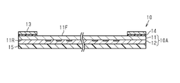
- the inspection seal unit 10 includes a base film 11, an adhesive layer 12, and a support 13.
- the base film 11 includes a front surface 11F and a back surface 11R that is a surface opposite to the front surface 11F.
- the adhesive layer 12 is located on the back surface 11R of the base film 11.
- the base film 11 and the adhesive layer 12 form the seal body 10A.
- the support 13 is attached to the surface 11F of the base film 11.
- the support 13 may be directly attached to the surface 11F of the base film 11 or indirectly.
- the inspection seal unit 10 further includes an adhesive layer 14 for attaching the support 13 to the surface 11F of the base film 11.
- the support 13 is indirectly attached to the surface 11F of the base film 11 via the adhesive layer 14.
- the base film 11 is made of synthetic resin.
- the base film 11 is made of polyurethane resin, for example.
- the base film 11 may be formed of a synthetic resin other than the polyurethane resin as long as the following two conditions are satisfied.
- the thickness of the base film 11 may be, for example, 5 ⁇ m or more and 15 ⁇ m or less.
- the tensile elongation at break is 130% or more.
- the 100% elongation tensile stress is 10 MPa or less.
- the tensile elongation at break can be measured according to JIS K7127:1999 (ISO 527-3:1995) "Plastics-Testing method for tensile properties-Part 3: Test conditions for film and sheet” and JIS K7161-1:2014 (ISO 527-1:2012) "Plastics-Determination of tensile properties-Part 1: General rules". If the test piece that is the object of measurement does not have a yield point, calculate the "tensile fracture strain" defined in JIS K7161-1:2014 3.7.2 as the tensile fracture elongation.
- the "nominal tensile strain at break" defined in 3.8.1 of the standard is calculated as the tensile elongation at break.
- the tensile breaking strain is calculated by the following formula (1) described in 10 “Expression of calculation and test result” of the standard.
- the tensile strain at break is calculated by the following equation (2) described in 10 “Expression of Calculation and Test Results” of the standard.
- ⁇ strain (%)
- L 0 is the distance between marked lines of the test piece (mm)
- ⁇ L 0 is an increase amount (mm) between marked lines of the test piece. is there.
- ⁇ t is the nominal strain (%)
- ⁇ y is the yield strain (%)
- L is the initial inter-grab tool distance (mm)
- ⁇ L t is from the yield point. It is the amount of increase (mm) in the distance between the grips.
- ⁇ F/A Equation (3)
- ⁇ stress (MPa)
- F measured force (N)
- A the initial cross-sectional area (mm 2 ) of the test piece.
- the adhesive layer 12 is made of synthetic resin.
- the adhesive layer 12 is made of polyurethane resin, for example.
- the adhesive layer 12 is a synthetic resin other than a polyurethane resin as long as the seal body 10A, which is a laminate of the base film 11 and the adhesive layer 12, satisfies the following Condition 3 in addition to Condition 1 and Condition 2 described above. May be formed from
- the thickness of the adhesive layer 12 may be, for example, 5 ⁇ m or more and 25 ⁇ m or less. (Condition 3)
- the moisture permeability specified in JIS Z 0208 is 750 g/m 2 ⁇ day or more under the conditions of 40° C. and 90% relative humidity.
- the support 13 may be made of paper or synthetic resin.
- the support 13 preferably has higher rigidity than the seal body 10A.
- the rigidity and flexibility of the support 13 can be adjusted by the basis weight of the paper.
- the rigidity and flexibility of the support 13 can be adjusted by the type of synthetic resin and the thickness of the support 13.
- the inspection seal unit 10 further includes a protective film 15.
- the protective film 15 is releasably laminated on the back surface 11R of the base film 11.
- the protective film 15 covers the entire base film 11 when viewed from the viewpoint facing the protective film 15.
- the protective film 15 is preferably made of transparent or translucent synthetic resin.
- the protective film 15 is composed of, for example, a base film and a release layer.
- the release layer is laminated on the base film. In the protective film 15, the release layer is in contact with the adhesive layer 12.
- the base film may be, for example, a polyethylene terephthalate (PET) film or the like.
- PET polyethylene terephthalate
- the release layer may be, for example, a silicone resin layer.
- the protective film 15 may be formed only from the base film, and the surface of the base film that is in contact with the base film 11 may be processed to enhance the peeling property.
- the support 13 has a shape along the peripheral edge 11E of the base film 11 in a plan view facing the surface 11F of the base film 11.
- the support 13 includes a strip-shaped portion that connects two points facing each other on the peripheral edge 11E with the central portion 11M of the base film 11 interposed therebetween.
- the central portion 11M of the base film 11 is a portion having a half area with respect to the area of the surface 11F and having a peripheral edge similar to the peripheral edge 11E of the base film 11, and the peripheral edge of the base film 11.
- the distance from 11E is equal between arbitrary points on the peripheral edge of the central portion 11M.
- the support 13 has a polygonal shape that surrounds the entire central portion 11M.
- the support body 13 is a closed annular and rectangular frame body.
- the support 13 is located on the entire periphery 11E of the base film 11.
- a pair of sides facing each other in the vertical direction of the paper surface is defined as a first side 13b1 and a second side 13b2, both sides facing each other in the left-right direction of the paper face the first side 13b1. It is defined as a connection side 13b3 connected to the second side 13b2.
- the first side 13b1 is a side including the first point P1 which is one of the two points described above, and the second side 13b2 includes the second point P2 which is the other point of the two points described above. It's an edge.
- the support 13 has a rectangular frame shape including the first side 13b1, the second side 13b2, and the connection side 13b3.
- the belt-shaped portion forms a part of the first side 13b1, a part of the second side 13b2, and one connecting side 13b3. I have it.
- the seal body 10A is supported by the support body 13, a portion of the periphery of the seal body 10A supported by the support body 13 is maintained in a state of being extended according to the shape of the support body 13. .. Therefore, an inspector who attaches the seal body 10A to the breast simply pulls only the part of the periphery of the seal body 10A that is not supported by the support 13 toward the outside to make the entire seal body 10A wrinkle-free. It is possible to maintain it in a non-existent state. As a result, the seal body 10A having no wrinkles can be attached to the breast, so that the seal body 10A attached to the breast can be prevented from wrinkling. As described above, according to the inspection seal unit 10 having the support 13, it is possible to improve the work efficiency in the inspection.
- the tester is, for example, a doctor or a technician.
- the base film 11 has a coordinate grid 16 for guiding the scan position on the inspection target.
- the coordinate grid 16 is located in a region surrounded by the support 13 in a plan view facing the surface 11F of the base film 11.
- the coordinate grid 16 includes a plurality of first grid lines 16a. Each of the first grid lines 16a extends along the scan direction, and the plurality of first grid lines 16a are arranged along the arrangement direction intersecting with the scan direction.
- the up-down direction of the paper surface is the scanning direction
- the left-right direction of the paper surface is the arrangement direction.
- the scan direction is a direction in which an inspection person scans an inspection object using a probe in mammography.
- the coordinate grid 16 further includes a plurality of second grid lines 16b extending along the arrangement direction and lined up along the scanning direction. When viewed from the direction facing the surface 11F of the base film 11, the plurality of second grid lines 16b form a square lattice together with the plurality of first grid lines 16a.
- the coordinate grid 16 is printed on the back surface 11R of the base film 11 using ink.
- ink for printing the coordinate grid 16 any ink that can print on the base film 11 can be used.
- the total light transmittance defined by JIS K 7361-1 is 50% or more. Accordingly, when the inspection seal unit 10 is attached to the breast, it is possible to adjust the position of the inspection seal unit 10 with respect to the breast while visually confirming the position of the coordinate grid 16 with respect to the breast. In addition, if the total light transmittance of the inspection seal unit 10 is 50% or more, after the base film 11 and the adhesive layer 12 are attached to the breast, the positions of moles and stains located on the breast through them are determined. , It is possible to identify by visual inspection or camera. Since the positions of moles and stains on the breast do not change, the positions of moles and stains on the breast are important in identifying the location of lesions on the breast.
- the total light transmittance defined by JIS K 7361-1 is preferably lower than the total light transmittance in the portion of the seal body 10A excluding the coordinate grid 16.
- the support 13 is preferably translucent or opaque.
- the boundary between the seal body 10A and the support body 13 is clearer than when the support body 13 has the same level of transparency as the seal body 10A. Therefore, when the support 13 is removed from the inspection seal unit 10, it is easy to determine whether or not the seal body 10A is cut along the support 13. Thereby, when the support 13 is removed from the inspection seal unit 10, it is possible to prevent the inside of the boundary between the seal body 10A and the support 13 from being accidentally cut.
- the support 13 has a fragile portion 13a.
- the fragile portion 13a is a portion that is more easily broken than the portion of the support 13 other than the fragile portion 13a.
- the fragile portion 13a is a portion having lower mechanical strength than the portion of the support 13 other than the fragile portion 13a. Since the support 13 has the fragile portion 13a, the support 13 can be broken at the fragile portion 13a. Therefore, it is easy to remove the support 13 from the surface 11F of the base film 11 triggered by the breakage in the fragile portion 13a.
- the breaking strength of the support 13 at portions other than the fragile portion 13a is higher than the breaking strength of the base film 11, and the adhesion strength between the support 13 and the surface 11F of the base film 11 is higher than the adhesion strength with the inspection target. high.
- the seal body 10A is ruptured along the boundary between the support 13 and the base film 11 in plan view facing the surface 11F of the base film 11. It is possible.
- the portion of the seal body 10A that overlaps the support 13 is removed from the breast together with the support 13. It is possible.
- the breaking strength specified by JIS K 7127 is preferably 35 N/25 mm or less, and more preferably 25 N/25 mm or less.
- the breaking strength of the base film 11 is within the range of 35 N/25 mm or less, it is easy to break the seal body 10A together with the support 13.
- the fragile portion 13a is located at a portion of the support 13 that includes the largest distance from the center of gravity of the base film 11 in a plan view facing the surface 11F of the base film 11.
- the seal body 10A has a rectangular shape and the support 13 has a rectangular frame shape when viewed from the direction facing the surface 11F of the base film 11. Therefore, the portion of the support 13 that includes the point having the largest distance from the center of gravity of the base film 11 is each corner of the support 13.
- the support 13 has a first corner 13c1 where the first side 13b1 and the connecting side 13b3 intersect, and a second corner 13c2 where the second side 13b2 and the connecting side 13b3 intersect. It is preferable that the support 13 includes a fragile portion 13a on at least one of the first corner portion 13c1 and the second corner portion 13c2.
- the periphery of the fragile portion 13a is easily grasped, and therefore the force for breaking the fragile portion 13a is increased. It is easy to act on 13a.
- the fragile portion 13a is located at both the first corner portion 13c1 and the second corner portion 13c2. Therefore, the degree of freedom in attaching the inspection seal unit 10 to the inspection target is increased as compared with the case where the support 13 has only one fragile portion 13a.
- the left breast and the right breast according to the specifications including the fragile portion 13a in both the first corner 13c1 and the second corner 13c2. It is possible to obtain the effect of the fragile portion 13a both on the breast.
- FIG. 3 shows an enlarged plan structure of the fragile portion 13a located at the second corner portion 13c2.
- the fragile portion 13a is a perforation 13am. Therefore, it is possible to break the support 13 along the perforations 13am.
- the support 13 includes an outer peripheral edge 13e1 and an inner peripheral edge 13e2.
- the inner peripheral edge 13e2 is a portion whose distance from the central portion 11M of the base film 11 is smaller than that of the outer peripheral edge 13e1.
- the perforation 13am includes an arrow shape from the outer peripheral edge 13e1 toward the inner peripheral edge 13e2.
- the inner peripheral edges of the corners 13c1 and 13c2 of the support 13 have an arc shape having a center of curvature in the base film 11.
- a portion of the inner peripheral edge 13e2 corresponding to each of the corners 13c1 and 13c2 has an arc shape having a center of curvature in the base film 11. Therefore, the inner peripheral edge easily follows the shape of a breast having a curved surface, and when the seal main body 10A surrounded by the inner peripheral edge 13e2 is attached to the breast, the seal main body 10A is less likely to wrinkle.
- the inner peripheral edge since the inner peripheral edge has the curvature, it is easier to cut the support 13 from the outer peripheral edge 13e1 toward the inner peripheral edge 13e2, as compared with the case where the corner portions 13c1 and 13c2 are formed by two straight lines.
- the portion of the outer peripheral edge 13e1 corresponding to each of the corners 13c1 and 13c2 has an arc shape having the center of curvature in the base film 11. This prevents the skin of the subject from being damaged by the corners 13c1 and 13c2 due to the outer peripheral edge 13e1 having a curvature.
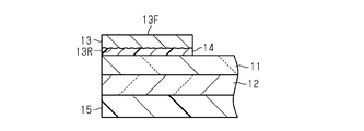
- FIG. 4 shows an enlarged part of the cross-sectional structure of the inspection seal unit 10 in FIG.
- the support 13 includes a back surface 13R and a front surface 13F.
- the back surface 13R of the support 13 is a surface facing the base film 11.
- the front surface 13F of the support 13 is a surface opposite to the back surface 13R.
- the surface roughness on the back surface 13R of the support 13 is larger than the surface roughness on the surface 13F of the support 13.
- the back surface 13R of the support body 13 and the support body 13 are formed. It is possible to increase the contact area with the object to be bonded. Thereby, the adhesiveness between the base film 11 and the support 13 can be improved.
- the contact area between the support 13 and the adhesive layer 14 can be increased. Thereby, peeling at the interface between the support 13 and the adhesive layer 14 is less likely to occur, and as a result, the adhesion of the support 13 to the base film 11 is enhanced.
- the surface roughness of the front surface 13F and the back surface 13R of the support 13 is evaluated by, for example, the arithmetic average roughness Ra, the maximum height Rz, the maximum peak height Rp, and the maximum valley depth Rv defined in JIS B0601. It is possible to
- the rigidity of the support 13 may be lower or higher than the rigidity of the protective film 15.
- the rigidity of the support 13 is lower than the rigidity of the protective film 15, when the adhesive layer 12, the base film 11, and the laminated body of the support 13 are attached to the breast and bent according to the curved surface of the breast, Bending following the shape of the breast is easier.
- the rigidity of the support 13 is higher than the rigidity of the protective film 15, the protective film 15 is easily peeled from the adhesive layer 12 when the inspection seal unit 10 is used, and the adhesive is applied after peeling the protective film 15. Wrinkling of the seal body 10A is suppressed until the layer 12 is attached to the breast.
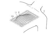
- FIG. 5 when using the inspection seal unit 10, the user first peels off the protective film 15 from the adhesive layer 12.
- the seal body 10A formed of the base film 11 and the adhesive layer 12 is used for the inspection of the breast.
- the adhesive layer 12 is attached to the breast B of the subject S.
- the inspector grips, for example, one side of the pair of sides of the support body 13 with one hand together with a part of the seal body 10A overlapping with the side, and the other side of the side. It is gripped with the other hand together with a part of the seal body 10A that overlaps the side. Deformation of the seal body 10A is restricted by the support 13 so that the shape of the seal body 10A does not change, and further, the inspector can apply a force to the seal body 10A so that the pair of sides are separated from each other. Therefore, it is possible to prevent the seal body 10A from wrinkling.
- the seal body 10A is extremely thin and satisfies the conditions 1 and 2, the seal body 10A extends very well by applying a small force to the seal body 10A. Therefore, in order to attach the seal body 10A having a rectangular shape and an area large enough to cover the entire breast B to the breast B without wrinkles, the periphery of the seal body 10A is formed. It is necessary to pull the sides outward. That is, it is necessary to attach the seal body 10A to the breast B by two or more testers.
- the inspection seal unit 10 of the present embodiment since the seal body 10A is supported in a state in which the deformation is regulated by the support body 13, one inspection person can seal the seal body 10A to the breast. Even if it is attached to B, it is possible to prevent wrinkles from occurring in the seal body 10A when the seal body 10A is attached. As described above, since it is possible to reduce the number of persons who perform the inspection, the inspection seal unit 10 can improve the working efficiency in mammography. Furthermore, according to the inspection seal unit 10 of the present embodiment, it is possible to attach the seal body 10A to the breast B without wrinkling of the seal body 10A. Therefore, the time and effort for reattaching the wrinkled portion of the seal body 10A is reduced. This can also improve the working efficiency in mammography.
- one of the corners 13c1 and 13c2 having the weakened portion 13a is located closer to the midline of the subject S than the corners other than the corner, and the head It is preferable to locate it closer to the part.
- the fragile portion 13a can be positioned on the ribs of the subject S, and therefore, when the support 13 is broken with the fragile portion 13a as a trigger, a force is easily applied to the fragile portion 13a.
- the support 13 is broken by using the fragile portion 13a as a trigger, and the support 13 is removed from the seal body 10A together with a part of the seal body 10A.
- the seal body 10A extends very well with only a small force applied. Therefore, it is difficult to remove only the support body 13 from the seal body 10A without breaking the support body 13 and without sticking the seal body 10A to the breast.
- the support 13 is broken by the fragile portion 13a as a trigger, and then the support when viewed from the direction facing the surface 11F of the base film 11. It is possible to break the seal body 10A along the support 13 at the boundary between the seal body 13 and the seal body 10A. Therefore, when the support body 13 is removed from the seal body 10A, it is possible to prevent the seal body 10A from wrinkling.
- the inspection seal unit 10 may be traded in a state in which the protective film 15, the adhesive layer 12, the base film 11, and the support 13 are integrated.
- the seal body 10A with the protective film 15 and the support 13 may be traded in separate states.
- the seal body 10A includes a separate film that covers the base film 11.
- the support 13 when the support 13 is attached to the seal body 10 ⁇ /b>A via the adhesive layer 14, the support 13 preferably has the adhesive layer 14.
- the support 13 has the adhesive layer 14 and the support 13 is traded separately from the seal body 10A with the protective film 15, the adhesive layer 14 laminated on the support 13 is protected. It is preferable that the support 13 has a protective film.
- the inspection seal unit 10 may be in the following forms.
- the inspection seal unit 10 includes a base film 11, an adhesive layer 12, and a support 13 to be attached to the surface 11F of the base film 11.
- the support 13 has a shape along the peripheral edge 11E of the base film 11 in a plan view facing the front surface 11F in a state of being attached to the front surface 11F of the base film 11, and the central portion of the base film 11 is A strip-shaped portion that connects two points facing each other at the peripheral edge 11E is provided.
- Example 1 An example and a comparative example of the inspection seal unit will be described with reference to Table 1.
- Example 1 to Example 5 and Comparative Example 1 a seal film-attached seal body common to them was prepared by the method described below.
- a PET film having a thickness of 75 ⁇ m and having a silicone coating on one side was prepared as a protective film (therapy is a registered trademark). Then, the silicone coated surface of the PET film was coated with 100 parts of a urethane-based adhesive (Toyochem Co., Siavine SP-205) and 1 part of a curing agent (T-501B). Then, an adhesive layer having a thickness of 15 ⁇ m was formed (Siavine is a registered trademark).
- a biaxially oriented polypropylene (OPP) film (FOR-MP, manufactured by Futamura Chemical Co., Ltd.) having a thickness of 40 ⁇ m was prepared as a separate film.
- OPP organic polypropylene
- a water-based urethane resin (WS-6021, manufactured by Mitsui Chemicals, Inc.) was applied to the separate film to form a base film having a thickness of 15 ⁇ m. Further, a coordinate grid for inspection was printed on the back surface of the base film.
- the pressure-sensitive adhesive layer formed by the above-mentioned coating was adhered to the back surface of the base film, which was a printing surface, and then the separate film was peeled from the base film to obtain a protective film-attached seal body.
- Example 1 A seal body with a protective film was prepared by the same method as in Comparative Example 1. Next, a support having a shape along three sides of the periphery of the seal film-attached seal body except one side extending in the lateral direction was prepared. In the support, the width, which is the length in the direction orthogonal to the direction in which each side extends, was set to 10 mm. As a material forming the support, a paper material having a basis weight of 260 g/m 2 (manufactured by Takeo Co., Ltd., Invercoat M-FS) was used. By attaching a support to the surface of the base film, the inspection seal unit of Example 1 was obtained.
- Example 2 An inspection seal unit of Example 2 was obtained by the same method as in Example 1 except that a support having a rectangular frame shape along the periphery of the seal body with a protective film was prepared in Example 1.
- the inspection seal of the third embodiment is manufactured by the same method as that of the second embodiment, except that a notch that is recessed from the outer peripheral edge to the inner peripheral edge of the support is formed at one corner of the support. I got a unit.
- Example 4 A sealing unit for inspection of Example 4 was obtained by the same method as in Example 2 except that perforations extending from the outer peripheral edge to the inner peripheral edge of the support were formed in one corner of the support in Example 2. ..
- Example 5 The seal unit for inspection of Example 5 is the same as that of Example 4 except that the seal main body with the protective film is formed into a circular shape having a radius of 140 mm and the annular support is formed.
- test seal unit of Examples 1 to 5 and the test seal unit of Comparative Example 1 were attached to the breast of a breast cancer palpation training model (manufactured by Tanac Co., Ltd.) by one experimenter.
- the seal body was attached together with the support to the breast cancer palpation training model.
- Comparative Example 1 after the protective film was removed from the adhesive layer and the separate film was removed from the base film, the seal body was attached to the breast cancer palpation training model. At this time, the following three items were evaluated.
- Table 1 shows the results of evaluating the above items 1 to 3 with respect to the inspection seal unit of Examples 1 to 5 and the inspection seal unit of Comparative Example 1.
- the inspection seal unit of Example 1 When the inspection seal unit of Example 1 is used, since three sides at the periphery of the seal body are pulled by the support, one experimenter pulls the remaining one side to The rim could be pulled evenly. Therefore, when the inspection seal unit of Example 1 is used, the seal body is attached to the breast without wrinkles in the area used for inspection even if wrinkles occur in the peripheral portion of the seal body. I was able to attach it. That is, according to Example 1, it was confirmed that the seal body can be attached to the breast without wrinkles to the extent that the inspection is not hindered. Further, in the state where the seal body was attached to the breast, the seal body could be ruptured along the support body at the boundary between the open end of the support body and the seal body. Thus, according to the inspection seal of Example 1, the support could be removed from the seal body while maintaining the state in which the seal body was attached to the breast.
- the inspection seal unit of Example 3 When the inspection seal unit of Example 3 was used, the entire periphery of the seal body was pulled by the support, so the periphery of the seal body could be pulled uniformly. Therefore, when the inspection seal unit of Example 3 was used, the seal main body could be attached to the breast without wrinkling of the seal main body. In addition, in the inspection seal of Example 3, since the support has a notch, the support is ruptured by the notch, and a part of the seal body where the support is attached is part of the seal. could be fractured with the support. As a result, by breaking the seal body along the boundary between the seal body and the support body, the support body could be removed from the seal body while maintaining the state in which the seal body stuck to the breast.
- the inspection seal unit of Example 4 When the inspection seal unit of Example 4 was used, the entire periphery of the seal body was pulled by the support, so the periphery of the seal body could be pulled uniformly. Therefore, when the test seal unit of Test Example 4 was used, the seal main body could be attached to the breast without wrinkling.
- the support since the support has perforations, the support was ruptured by the perforations, and one of the portions of the seal body to which the support adhered was broken. The part could be broken along with the support. As a result, by breaking the seal body along the boundary between the seal body and the support body, the support body could be removed from the seal body while maintaining the state in which the seal body stuck to the breast.
- the effects listed below can be obtained. (1) Since the seal body 10A is supported by the support body 13, a part of the seal body 10A supported by the support body 13 is extended in accordance with the shape of the support body 13. Maintained. Therefore, an inspector who attaches the seal body 10A to the breast B only wrinkles the entire seal body 10A by pulling only the part of the periphery of the seal body 10A that is not supported by the support 13 toward the outside. It is possible to maintain the state without. As a result, the seal body 10A having no wrinkles can be attached to the breast B, so that the seal body 10A attached to the breast B can be prevented from wrinkling. As described above, according to the inspection seal unit 10 having the support body 13, it is possible to improve the efficiency of the operation in the inspection.
- the inner peripheral edge Since the inner peripheral edge has a curvature, the inner peripheral edge easily follows the shape of the breast B having a curved surface. Therefore, when the seal main body 10A surrounded by the inner peripheral edge is attached to the breast B, the seal main body is attached. Wrinkles are less likely to occur at 10A.
- At least one of the outer peripheral edge 13e1 and the inner peripheral edge 13e2 of the support 13 may not have a curvature at each corner.
- at least one of the outer peripheral edge 13e1 and the inner peripheral edge 13e2 each corner may be formed by two straight lines.
- at least one of the outer peripheral edge 13e1 and the inner peripheral edge 13e2 may include both a corner formed by two straight lines and a corner having a curvature. Even in this case, as long as the inspection seal unit 10 has the support 13, the effect according to (1) described above can be obtained.
- the surface roughness on the back surface 13R of the support 13 may be equal to or less than the surface roughness on the surface 13F. Even in this case, as long as the inspection seal unit 10 has the support 13, the effect according to (1) described above can be obtained.
- the support 13A may have a cutout 13ak that is recessed from the outer peripheral edge 13e1 of the support 13 toward the inner peripheral edge 13e2 instead of the perforation 13am as the weakened portion 13a. Even in this case, the effect according to (3) described above can be obtained.
- the support 13B may have a polygonal line shape that surrounds the central portion 11M by leaving a part of the peripheral edge 11E of the base film 11 open.
- the seal main body 10 ⁇ /b>A having a rectangular shape may have a shape along a pair of sides facing each other and one side connecting the pair of sides in the peripheral edge of the seal body 10 ⁇ /b>A. That is, the support 13B may include only the first side 13B1, the second side 13B2 facing the first side 13B1, and the connecting side 13B3 connecting the first side 13B1 and the second side 13B2. Even in this case, the effect according to (2) described above can be obtained.
- the seal body 10A is broken by using the end of the first side 13B1 that is not connected to the connection side 13B3 or the end of the second side 13B2 that is not connected to the connection side 13B3 as a trigger. It is possible. Therefore, even if the support 13B does not have the fragile portion 13a, it is possible to remove the support 13B from the seal body 10A with the seal body 10A attached to the breast B.
- the support 13B may have a weakened portion 13a.
- the support 13C may have a circular shape that surrounds the entire central portion 11M of the base film 11.
- the seal body 10A1 may have a circular shape
- the support 13C may have a ring shape along the peripheral edge of the seal body 10A1.
- the support 13C may have a closed annular shape as shown in FIG. 10, or an open annular shape, that is, a part of the peripheral edge 11E of the base film 11 is left and the center is formed. It may have an arc shape surrounding the portion. Even in this case, the effect according to (2) described above can be obtained.
- the rigidity of the support 13 is preferably higher than the rigidity of the seal body 10A, but the rigidity of the support 13 may be equal to or less than the rigidity of the seal body 10A. Even in this case, the seal body 10A can be supported by the support 13 along the peripheral edge 11E of the base film 11 to obtain the effect according to (1) described above.
- the fragile portions 13 a may be located at each of the four corners of the support 13. Further, as shown in FIG. 11, when the first side 13b1 and the second side 13b2 are longer than the connection side 13b3, the support body 13 has a structure in which the first side 13b1 extends and the second side 13b2 extends. At least one of them can have a weakened portion 13a.
- the fragile portion 13a located in the middle of the extension of the first side 13b1 can be located closer to the corner of the support 13 than the central portion of the first side 13b1 in the extending direction of the first side 13b1.
- the fragile portion 13a located on the way of extending the second side 13b2 can be located closer to the corner of the support 13 than the central portion of the second side 13b2 in the extending direction of the second side 13b2.
- fragile portions 13a are located at each of the four corners of the support 13, and two fragile portions 13a are located at each of the first side 13b1 and the second side 13b2.
- the two fragile portions 13a located on the first side 13b1 are located near different corners of the corners of the support 13 with respect to the center of the first side 13b1 in the direction in which the first side 13b1 extends.
- the two fragile portions 13a located on the second side 13b2 are located near different corners of the corners of the support 13 with respect to the center of the second side 13b2 in the direction in which the second side 13b2 extends. doing.
- the seal main body 10A Since the breast B to which the seal main body 10A is attached has a bowl shape, when the seal main body 10A to which the support 13 is attached is attached to the breast B, the seal main body 10A is set at four corners of the support 13. Easy to get rid of.
- the support 13 may include a fragile portion 13a located on the way of extension of the connection side 13b3.
- the plurality of weak portions 13a include a weak portion 13a formed by perforations 13am and a weak portion 13a formed by a cutout 13ak. May be.
- the part of the support 13 where the fragile part 13a is located does not have to include the part having the largest distance from the center of gravity of the base film 11. Even in this case, the effect according to (3) described above can be obtained.
- the fragile portion 13a may be located only on one of the first corner portion 13c1 and the second corner portion 13c2. Even in this case, the effect according to (3) described above can be obtained.
- the perforations 13am may be straight. Even in this case, since it is possible to break the support 13 by using the perforations 13am as a trigger, it is possible to obtain the effect according to (3) described above.
- the support 13 may not have the fragile portion 13a. Even in this case, the effect according to (1) described above can be obtained.
- the breast B may be inspected with the support 13 attached to the seal body 10A, or the breast B may be inspected after the support 13 is removed from the seal body 10A. May be.
- the inspection seal unit 10 does not need to have the adhesive layer 14 for adhering the support 13 to the base film 11. Good. Even in this case, the surface roughness on the back surface 13R of the support 13 is preferably larger than the surface roughness on the surface 13F of the support 13. This makes it possible to improve the adhesion between the support 13 and the base film 11 as compared with the case where the surface 13F of the support 13 is adhered to the base film 11.
- the coordinate grid 16 may have a shape other than a square lattice in a plan view facing the surface 11F of the base film 11.
- the coordinate grid 16 may be composed of a plurality of concentric circles having different diameters. That is, the coordinate grid 16 may be a grid corresponding to polar coordinates.
- the coordinate grid 16 may have a shape capable of guiding the scanning direction and position of the probe while being attached to the breast B.
- the base film 11 is not limited to the coordinate grid 16 and may have a scan index having another shape such as a shape extending along one direction.
- the scan index may be, for example, one that guides the position to be scanned by the probe or that guides the scan direction.
- the coordinate grid 16 may not be formed by printing.
- the coordinate grid 16 may be formed by the recesses or protrusions of the base film 11.
- the synthetic resin for forming the base film 11 may be a resin other than the polyurethane resin as long as the base film 11 included in the inspection seal unit 10 satisfies the above conditions 1 and 2.
- the synthetic resin for forming the base film 11 may be EVA resin.
- the base film 11 does not have to satisfy at least one of the conditions 1 and 2 described above. Even in this case, if the inspection seal unit 10 includes the support 13 attached to the base film 11, the effect according to (1) described above can be obtained.
- the breaking strength in the portion other than the weakened portion 13a may be equal to or lower than the breaking strength of the base film 11.
- at least a part of the fragile portion 13a can be removed from the seal body 10A when the support 13 is broken at the fragile portion 13a.
- the adhesion strength between the support 13 and the surface 11F of the base film 11 may be equal to or less than the adhesion strength between the adhesive layer 12 and the breast B. In this case, the support 13 after being broken at the weakened portion 13a is easily peeled off from the base film 11.
- the seal body 10A does not have to satisfy the above condition 3. Even in this case, if the inspection seal unit 10 includes the support 13 attached to the base film 11, the effect according to (1) described above can be obtained.
- the protective film 15 may be omitted. Even in this case, if the inspection seal unit 10 includes the support 13 attached to the base film 11, the effect according to (1) described above can be obtained.
- the inspection seal unit 10 may further include a protective layer that covers the surface 11F of the base film 11.
- FIG. 12 shows a cross-sectional structure of the inspection seal unit 10 along a cross section orthogonal to the surface 11F of the base film 11.
- the inspection seal unit 10 further includes a protective layer 17 that covers the surface 11F of the base film 11.
- the protective layer 17 covers a portion of the surface 11F of the base film 11 inside the support 13 when viewed from a viewpoint facing the surface 11F of the base film 11.
- the protective layer 17 is in contact with the surface 11F of the base film 11 and has a shape parallel to the surface 11F.
- the protective layer 17 may have bending.
- the protective layer 17 has a convex shape extending from the peripheral edge of the protective layer 17 toward the center in the direction from the base film 11 to the adhesive layer 12.
- the protective layer 17 may have a planar shape that is located on the same plane as the support 13 in the thickness direction of the seal body 10A.
- the inspection seal unit 10 may have a gap corresponding to the thickness of the adhesive layer 14 between the surface 11F of the base film 11 and the protective layer 17 in the thickness direction of the seal body 10A. ..
- the protective layer 17 can have any of the shapes described above, depending on the rigidity of the protective layer 17.
- FIG. 13 shows a planar structure of the inspection seal unit 10 as viewed from a viewpoint facing the surface 11F of the base film 11.
- the protective layer 17 covers almost the entire inner portion of the support 13 when viewed from the viewpoint facing the surface 11F of the base film 11.
- the protective layer 17 has a shape similar to the shape of the inner peripheral edge of the support 13. As a result, the protective layer 17 can cover most of the surface 11F of the base film 11 exposed from the support 13.
- the protective layer 17 and the support 13 are separated from each other by a gap G located between the protective layer 17 and the support 13.
- a connecting portion 18 that connects the protective layer 17 and the support 13 is located in the gap G.
- the inspection seal unit 10 can include one or more connecting portions 18.
- the inspection seal unit 10 includes a plurality of connecting portions 18, and the protection layer 17 has a circumferential direction. In, it is preferable that the plurality of connecting portions 18 are spaced from each other.
- the length of the connecting portion 18 along the circumferential direction of the protective layer 17 is shorter than the length of the protective layer 17 along the circumferential direction in the gap G between the two connecting portions 18.
- the protective layer 17 may be made of paper or synthetic resin.
- the material forming the protective layer 17 may be the same as the material forming the support 13. In this case, one member for forming the support 13 and the protective layer 17 is prepared, and the support 13, the protective layer 17, and the connecting portion 18 are removed from the member by punching or laser processing. Can be formed.
- the fragile portion 13a included in the support 13 can also be formed using the same processing method. is there.
- the protective layer 17 is separated from the support 13 by breaking the connecting portion 18.
- the connecting portion 18 By exposing a part of the surface 11F of the base film 11, the coordinate grid 16 formed on the base film 11 can be exposed to the outside.
- the inspection seal unit 10 including the protective layer 17 the following effects can be obtained. (11) Since the portion of the surface 11F of the base film 11 exposed from the support 13 is covered with the protective layer 17, keep the portion covered with the protective layer 17 clean until the seal body 10A is used for inspection. Is possible.
- the inspection seal unit 10 may not include the connecting portion 18 that connects the protective layer 17 to the support 13. Even in this case, since the inspection seal unit 10 includes the protective layer 17, it is possible to obtain the effect according to the above (11).
- the protective layer 17 may have a shape that covers only a part of the portion of the surface 11F exposed from the support 13 when viewed from the viewpoint facing the surface 11F of the base film 11. Even in this case, at least in the portion of the surface 11F covered with the protective layer 17, the effect according to (11) described above can be obtained.
- the protective layer 17 may cover both the support 13 and a portion of the surface 11F of the base film 11 inside the support 13 when viewed from the viewpoint facing the surface 11F of the base film 11. Good. In this case, it is preferable that the protective layer 17 be flexible so that it can have a shape that conforms to the height difference formed by the support 13 and the surface 11F of the base film 11.
- the subject to be examined is not limited to the breast, and may be another part of the human body. That is, the inspection seal unit 10 may be used not only for mammography but also for other image diagnosis.
Landscapes
- Health & Medical Sciences (AREA)
- Life Sciences & Earth Sciences (AREA)
- Surgery (AREA)
- Medical Informatics (AREA)
- Engineering & Computer Science (AREA)
- General Health & Medical Sciences (AREA)
- Veterinary Medicine (AREA)
- Biomedical Technology (AREA)
- Heart & Thoracic Surgery (AREA)
- Oral & Maxillofacial Surgery (AREA)
- Molecular Biology (AREA)
- Animal Behavior & Ethology (AREA)
- Nuclear Medicine, Radiotherapy & Molecular Imaging (AREA)
- Public Health (AREA)
- Pathology (AREA)
- Chemical & Material Sciences (AREA)
- Organic Chemistry (AREA)
- Dentistry (AREA)
- Physics & Mathematics (AREA)
- Biophysics (AREA)
- High Energy & Nuclear Physics (AREA)
- Optics & Photonics (AREA)
- Radiology & Medical Imaging (AREA)
- Apparatus For Radiation Diagnosis (AREA)
- Chemical Kinetics & Catalysis (AREA)
Abstract
表面と表面とは反対側の面である裏面とを含むベースフィルムと、ベースフィルムの裏面に位置する粘着層と、ベースフィルムの表面に取り付けられ、表面と対向する平面視において、ベースフィルムの周縁の少なくとも一部に沿う形状を有する支持体であって、ベースフィルムの中央部を挟んで周縁において互いに対向する2点間を接続する帯状部を備える支持体とを備える。
Description
本発明は、マイクロ波を用いた画像診断に用いられる検査用シールユニットに関する。
乳がんの検査方法として、マイクロ波を用いたマンモグラフィーが提案されている(例えば、特許文献1を参照)。マイクロ波を用いたマンモグラフィーでは、検査対象である乳房を圧迫する必要がないため、被検者は検査時に痛みを感じることがない。また、マイクロ波を用いたマンモグラフィーではX線を用いないため、被検者が被爆しない。
マイクロ波を用いたマンモグラフィーでは、プローブによって乳房の全体をスキャンする。この際に、スキャン漏れが生じないように、座標グリッドが印字されたタトゥーシールが、乳房に貼り付けられる。タトゥーシールは、粘着層と受像層とを備えている(例えば、特許文献2,3を参照)。受像層には、インクジェットプリンターなどを用いて座標グリッドが形成される。
乳房を検査するための検査用シールとしてタトゥーシールを用いる場合には、検査用シールには、乳房の全体を覆うことが可能な程度に大きい面積を有することが必要とされる。検査用シールは非常に薄いため、検査用シールにはしわが生じやすい。それゆえに、検査用シールにしわが生じないように検査用シールを乳房に貼り付けるためには、検査用シールを一旦乳房に貼り付けた後に、検査用シールのなかでしわが生じた部分のみを乳房から剥がし、再度引き延ばして乳房に貼り付けることを繰り返すことが必要である。また、検査用シールの貼り直す回数を少なくするためには、検査用シールにしわを生じさせないように複数人で検査用シールを乳房に貼り付けることが必要である。このように、検査用シールを用いたマンモグラフィーでは、検査用シールを乳房に貼り付ける操作に手間がかかるため、操作の手間を削減することによって、検査の作業効率を高めることが求められている。
なお、こうした事項は、検査対象が乳房である場合に限らず、人体における他の部位である場合にも共通する。
本発明は、検査における作業の効率を高めることを可能とした検査用シールユニットを提供することを目的とする。
本発明は、検査における作業の効率を高めることを可能とした検査用シールユニットを提供することを目的とする。
上記課題を解決するための検査用シールユニットは、表面と前記表面とは反対側の面である裏面とを含むベースフィルムと、前記ベースフィルムの前記裏面に位置する粘着層と、前記ベースフィルムの前記表面に取り付けられ、前記表面と対向する平面視において、前記ベースフィルムの周縁の少なくとも一部に沿う形状を有する支持体であって、前記ベースフィルムの中央部を挟んで前記周縁において互いに対向する2点間を接続する帯状部を備える前記支持体と、を備える。
上記課題を解決するための検査用シールユニットは、表面と前記表面とは反対側の面である裏面とを含むベースフィルムと、前記ベースフィルムの前記裏面に位置する粘着層と、前記ベースフィルムの前記表面に取り付けるための支持体と、を備える。前記支持体は、前記表面に取り付けられた状態において、前記表面と対向する平面視にて、前記ベースフィルムの周縁に沿う形状を有し、かつ、前記ベースフィルムの中央部を挟んで前記周縁において互いに対向する2点間を接続する帯状部を備える。
上記各構成によれば、ベースフィルムと粘着層との積層体が支持体に支持されることによって、積層体の周縁のなかで、支持体によって支持された部分は、支持体が有する形状にしたがって延ばされた状態に維持される。そのため、積層体を検査対象に貼り付ける検査実施者は、積層体の周縁のなかで、支持体によって支持されていない部分のみを外側に向けて引っ張るのみで積層体の全体をしわのない状態に維持することが可能である。これにより、しわが寄っていない積層体を検査対象に貼り付けることが可能であるため、検査対象に貼り付けられた積層体にしわが生じることが抑えられる。このように、支持体を有した検査用シールユニットによれば、検査における作業の効率を高めることが可能である。
上記検査用シールユニットにおいて、前記支持体は、前記中央部の全体を囲む多角形状、前記周縁の一部を空けて前記中央部を囲む折れ線状、前記中央部の全体を囲む円形状、および、前記周縁の一部を空けて前記中央部を囲む弧状のいずれか一つの形状を有してもよい。
上記構成によれば、積層体のなかで支持体によって囲まれた領域が、支持体によって延ばされた状態に維持される。これにより、積層体が検査対象に貼り付けられる際に、積層体にしわが生じることが抑えられる。
上記検査用シールユニットにおいて、前記支持体は、前記支持体における脆弱部以外の部分よりも破断されやすい前記脆弱部を備えてもよい。この構成によれば、脆弱部をきっかけにして支持体を破断することが容易である。そのため、ベースフィルムの表面から支持体を取り外すことが容易である。
上記検査用シールユニットにおいて、前記脆弱部は、ミシン目であってもよい。この構成によれば、ミシン目に沿って支持体を破断することが可能になる。
上記検査用シールユニットにおいて、前記支持体における前記脆弱部以外の部分での破断強度は、前記ベースフィルムの破断強度よりも高く、前記支持体と前記表面との間の密着強度は、前記粘着層と検査対象との間の密着強度よりも高くてもよい。
上記構成によれば、脆弱部をきっかけとして支持体を破断した場合に、ベースフィルムの表面と対向する平面視における支持体とベースフィルムとの境界に沿って、ベースフィルムと粘着層との積層体を破断することが可能である。さらに、積層体の厚さ方向から見て、積層体のなかで支持体と重なる部分を、支持体とともに検査対象から取り除くことが可能である。
上記検査用シールユニットにおいて、前記脆弱部は、前記表面と対向する平面視において、前記支持体のなかで前記ベースフィルムの重心からの距離が最も大きい点を含む部位に位置してもよい。
上記構成によれば、脆弱部とベースフィルムの重心との距離がより小さい場合に比べて、ベースフィルムから支持体を取り外す際にベースフィルムと粘着層との積層体にしわが生じたり、検査対象に対する積層体の位置が変わったりすることが抑えられる。
上記検査用シールユニットにおいて、前記支持体は、前記1つの点のうちの第1点を含む第1辺と、前記2つの点のうちの第2点を含む第2辺と、前記第1辺と前記第2辺とを接続する接続辺とを備えた多角形状を有し、前記支持体は、前記第1辺と前記接続辺とが形成する第1角部と、前記第2辺と前記接続辺とが形成する第2角部とを有し、前記第1角部および前記第2角部の内周縁が、前記ベースフィルム上に曲率中心を有した弧状を有してもよい。
上記構成によれば、内周縁が曲率を有することによって、曲面を有した検査対象の形状に内周縁が沿いやすくなるため、内周縁に囲まれたベースフィルムと粘着層との積層体を検査対象に貼り付けた際に、積層体にしわが寄りにくくなる。また、内周縁が曲率を有することによって、角部が2つの直線によって形成される場合に比べて、外周縁から内周縁に向けた支持体の切断が容易である。
上記検査用シールユニットにおいて、前記支持体は、前記第1角部と前記第2角部との少なくとも一方に、前記支持体における脆弱部以外の部分よりも破断されやすい前記脆弱部を備えてもよい。この構成によれば、各辺が延びる途中に脆弱部が位置する場合に比べて、脆弱部の周囲を把持しやすいため、脆弱部を破断するための力を脆弱部に作用させやすい。
上記検査用シールユニットにおいて、前記支持体は、前記ベースフィルムに対向する裏面と、前記裏面とは反対側の面である表面とを含み、前記支持体の前記裏面における表面粗さが、前記支持体の前記表面における表面粗さよりも大きくてもよい。
上記構成によれば、支持体において相対的に表面粗さが大きい面がベースフィルムに対して取り付けられる裏面であることによって、支持体の裏面と支持体の接着対象との接触面積を大きくすることが可能である。これにより、ベースフィルムと支持体との密着性を高めることができる。
上記検査用シールユニットにおいて、前記表面と対向する平面視において、前記表面のうちで前記支持体よりも内側の部分を覆う保護層をさらに備えてもよい。
上記構成によれば、ベースフィルムの表面のうちで、支持体から露出した部分が保護層によって覆われるため、ベースフィルムと粘着層との積層体を検査に用いるまで保護層によって覆われた部分を清浄に保つことが可能である。
本発明によれば、検査における作業の効率を高めることができる。
図1から図7を参照して、検査用シールユニットの一実施形態を説明する。以下では、検査用シールユニットの構造、検査用シールユニットの使用方法、検査用シールユニットの流通形態、および、実施例を順に説明する。
[検査用シールユニットの構造]
図1から図4を参照して、検査用シールユニットの構造を説明する。本実施形態において、検査用シールユニットは、マイクロ波を用いた画像診断の一例であるマンモグラフィーに用いられる。本実施形態では、特に300MHz以上300GHz以下の波長帯域のマイクロ波を用いることが好ましい。検査用シールユニットは、マンモグラフィーにおいて、検査対象である乳房に貼り付けられるシール本体を含む。
図1から図4を参照して、検査用シールユニットの構造を説明する。本実施形態において、検査用シールユニットは、マイクロ波を用いた画像診断の一例であるマンモグラフィーに用いられる。本実施形態では、特に300MHz以上300GHz以下の波長帯域のマイクロ波を用いることが好ましい。検査用シールユニットは、マンモグラフィーにおいて、検査対象である乳房に貼り付けられるシール本体を含む。
図1が示すように、検査用シールユニット10は、ベースフィルム11、粘着層12、および、支持体13を備えている。ベースフィルム11は、表面11Fと表面11Fとは反対側の面である裏面11Rとを含んでいる。粘着層12は、ベースフィルム11の裏面11Rに位置している。ベースフィルム11と粘着層12とが、シール本体10Aを形成している。支持体13は、ベースフィルム11の表面11Fに取り付けられている。
支持体13は、ベースフィルム11の表面11Fに直接的に取り付けられてもよいし、間接的に取り付けられてもよい。本実施形態では、検査用シールユニット10は、支持体13をベースフィルム11の表面11Fに取り付けるための接着層14をさらに備えている。支持体13は、接着層14を介してベースフィルム11の表面11Fに間接的に取り付けられている。
ベースフィルム11は、合成樹脂製である。ベースフィルム11は、例えばポリウレタン樹脂製である。ベースフィルム11は、以下の2つの条件を満たしていれば、ポリウレタン樹脂以外の合成樹脂から形成されてもよい。ベースフィルム11の厚さは、例えば、5μm以上15μm以下であってよい。
(条件1)引張破断伸度が130%以上である。
(条件2)100%伸び引張り応力が10MPa以下である。
(条件1)引張破断伸度が130%以上である。
(条件2)100%伸び引張り応力が10MPa以下である。
引張破断伸度は、JIS K7127:1999(ISO 527-3:1995)の「プラスチック-引張特性の試験方法-第3部:フィルム及びシートの試験条件」、および、JIS K7161-1:2014(ISO 527-1:2012)の「プラスチック-引張特性の求め方-第1部:通則」に準拠して算出される。測定対象物である試験片が降伏点を有しない場合には、JIS K7161-1:2014の3.7.2に定義された「引張破壊ひずみ」を引張破断伸度として算出する。一方で、試験片が降伏点を有する場合には、当該規格の3.8.1に定義される「引張破壊呼びひずみ」を引張破断伸度として算出する。なお、引張破壊ひずみは、当該規格の10「計算及び試験結果の表現」に記載された以下の式(1)によって算出される。また、引張破壊呼びひずみは、当該規格の10「計算及び試験結果の表現」に記載された以下の式(2)によって算出される。
ε=ΔL0/L0 … 式(1)
εt=εy+ΔLt/L … 式(2)
なお、式(1)において、εはひずみ(%)であり、L0は試験片の標線間距離(mm)であり、ΔL0は試験片の標線間距離の増加量(mm)である。また、式(2)において、εtは呼びひずみ(%)であり、εyは降伏ひずみ(%)であり、Lは初めのつかみ具間距離(mm)であり、ΔLtは降伏点からのつかみ具間距離の増加量(mm)である。
εt=εy+ΔLt/L … 式(2)
なお、式(1)において、εはひずみ(%)であり、L0は試験片の標線間距離(mm)であり、ΔL0は試験片の標線間距離の増加量(mm)である。また、式(2)において、εtは呼びひずみ(%)であり、εyは降伏ひずみ(%)であり、Lは初めのつかみ具間距離(mm)であり、ΔLtは降伏点からのつかみ具間距離の増加量(mm)である。
100%伸び引張応力は、JIS K7127:1999(ISO 527-3:1995)の「プラスチック-引張特性の試験方法-第3部:フィルム及びシートの試験条件」に準拠し、JIS K7161-1:2014(ISO 527-1:2012)の「プラスチック-引張特性の求め方-第1部:通則」の3.6.3に定義された「x%ひずみ引張応力」において、ひずみが規定の値(100%)に達したときの応力として算出される。なお、100%ひずみ引張応力は、当該規格の10「計算及び試験結果の表現」に記載された以下の式(3)によって算出される。
σ=F/A … 式(3)
なお、式(3)において、σは応力(MPa)であり、Fは測定した力(N)であり、Aは試験片の初めの断面積(mm2)である。
なお、式(3)において、σは応力(MPa)であり、Fは測定した力(N)であり、Aは試験片の初めの断面積(mm2)である。
粘着層12は、ベースフィルム11と同様、合成樹脂製である。粘着層12は、例えばポリウレタン樹脂製である。粘着層12は、ベースフィルム11と粘着層12との積層体であるシール本体10Aにおいて、上述した条件1および条件2に加えて、以下の条件3を満たしていれば、ポリウレタン樹脂以外の合成樹脂から形成されてもよい。粘着層12の厚さは、例えば、5μm以上25μm以下であってよい。
(条件3)JIS Z 0208に規定される透湿度が、40℃かつ相対湿度90%の条件において、750g/m2・day以上である。
(条件3)JIS Z 0208に規定される透湿度が、40℃かつ相対湿度90%の条件において、750g/m2・day以上である。
支持体13は、紙製でもよいし、合成樹脂製でもよい。支持体13は、シール本体10Aよりも高い剛性を有することが好ましい。一方で、支持体13は、検査用シールユニット10が乳房などの曲面に適用された場合に、曲面に沿った湾曲を可能とする可撓性を有することが好ましい。支持体13が紙製である場合には、紙の坪量によって、支持体13の剛性と可撓性とを調整することが可能である。支持体13が合成樹脂製である場合には、合成樹脂の種類、および、支持体13の厚さによって、支持体13の剛性と可撓性とを調整することが可能である。
検査用シールユニット10は、保護フィルム15をさらに備えている。保護フィルム15は、ベースフィルム11の裏面11Rに対して剥離可能に積層されている。保護フィルム15と対向する視点から見て、保護フィルム15は、ベースフィルム11の全体を覆っている。保護フィルム15は、透明または半透明な合成樹脂製であることが好ましい。保護フィルム15は、例えば、基材フィルムと、離型層とから構成されている。離型層は、基材フィルム上に積層されている。保護フィルム15において、離型層が粘着層12に接している。基材フィルムは、例えば、ポリエチレンテレフタレート(PET)フィルムなどであってよい。離型層は、例えば、シリコーン樹脂製の層であってよい。なお、保護フィルム15は、基材フィルムのみから形成され、かつ、基材フィルムのなかでベースフィルム11と接する面に、剥離性を高める加工が施されていてもよい。
図2が示すように、ベースフィルム11の表面11Fと対向する平面視において、支持体13は、ベースフィルム11の周縁11Eに沿う形状を有している。支持体13は、ベースフィルム11の中央部11Mを挟んで周縁11Eにおいて互いに対向する2点間を結ぶ帯状部を備えている。なお、ベースフィルム11の中央部11Mとは、表面11Fの面積に対する半分の面積を有し、かつ、ベースフィルム11の周縁11Eと相似形の周縁を有した部分であって、ベースフィルム11の周縁11Eからの距離が、中央部11Mの周縁上の任意の点間で等しい部分である。
本実施形態において、支持体13は、中央部11Mの全体を囲む多角形状を有している。詳細には、支持体13は、閉環状、かつ、矩形状の枠体である。支持体13は、ベースフィルム11の周縁11Eにおける全体に位置している。本実施形態では、紙面の上下方向において互いに対向する一対の辺を第1辺13b1および第2辺13b2と定義した場合に、紙面の左右方向において互いに対向する辺の両方が、第1辺13b1を第2辺13b2に接続する接続辺13b3として定義される。第1辺13b1は上述した2点のうちの一方の点である第1点P1を含む辺であり、第2辺13b2は上述した2点のうちの他方の点である第2点P2を含む辺である。支持体13は、上述したように、第1辺13b1、第2辺13b2、および、接続辺13b3を含む矩形枠状を有している。本実施形態のように第1点P1および第2点P2を設定した場合には、帯状部が、第1辺13b1の一部、第2辺13b2の一部、および、一方の接続辺13b3を備えている。
シール本体10Aが支持体13に支持されることによって、シール本体10Aの周縁のなかで、支持体13によって支持された部分は、支持体13が有する形状にしたがって延ばされた状態に維持される。そのため、シール本体10Aを乳房に貼り付ける検査実施者は、シール本体10Aの周縁のなかで、支持体13によって支持されていない部分のみを外側に向けて引っ張るのみでシール本体10Aの全体をしわのない状態に維持することが可能である。これにより、しわが寄っていないシール本体10Aを乳房に貼り付けることが可能であるため、乳房に貼り付けられたシール本体10Aにしわが生じることが抑えられる。このように、支持体13を有した検査用シールユニット10によれば、検査における作業効率を高めることが可能である。なお、検査実施者は、例えば医師または検査技師などである。
ベースフィルム11は、検査対象におけるスキャンの位置を案内するための座標グリッド16を有している。座標グリッド16は、ベースフィルム11の表面11Fと対向する平面視において、支持体13によって囲まれる領域内に位置している。座標グリッド16は、複数の第1グリッド線16aを含んでいる。各第1グリッド線16aは、スキャン方向に沿って延び、かつ、複数の第1グリッド線16aは、スキャン方向と交差する配列方向に沿って並んでいる。本実施形態において、紙面の上下方向がスキャン方向であり、紙面の左右方向が配列方向である。スキャン方向は、マンモグラフィーにおいて、検査実施者が、プローブを用いて検査対象をスキャンする方向である。
座標グリッド16は、配列方向に沿って延び、かつ、スキャン方向に沿って並ぶ複数の第2グリッド線16bをさらに含んでいる。ベースフィルム11の表面11Fと対向する方向から見て、複数の第2グリッド線16bは、複数の第1グリッド線16aとともに正方格子を形成している。
座標グリッド16は、インキを用いてベースフィルム11の裏面11Rに印字されている。座標グリッド16を印字するためのインキには、ベースフィルム11に対する印字が可能な任意のインキを用いることが可能である。
検査用シールユニット10において、シール本体10Aのうちで、座標グリッド16を除く部分において、JIS K 7361-1に規定される全光線透過率が50%以上であることが好ましい。これにより、検査用シールユニット10を乳房に貼り付ける場合に、乳房に対する座標グリッド16の位置を目視によって確認しながら、乳房に対する検査用シールユニット10の位置を調整することが可能である。また、検査用シールユニット10の全光線透過率が50%以上であれば、ベースフィルム11と粘着層12とを乳房に貼り付けた後に、これらを介して乳房に位置するほくろやしみの位置を、目視やカメラによって特定することが可能である。乳房におけるほくろやしみの位置は変わらないため、乳房における病巣の位置を特定する上で、乳房におけるほくろやしみの位置は重要である。
これに対して、支持体13において、JIS K 7361-1に規定される全光線透過率は、シール本体10Aにおいて座標グリッド16を除く部分における全光線透過率よりも低いことが好ましい。支持体13は、半透明または不透明であることが好ましい。これにより、支持体13がシール本体10Aと同程度の透過性を有する場合に比べて、シール本体10Aと支持体13との境界が明確である。そのため、検査用シールユニット10から支持体13を取り除く場合に、支持体13に沿ってシール本体10Aが切断されているか否かの判断が容易である。これにより、検査用シールユニット10から支持体13を取り除く場合に、シール本体10Aと支持体13との境界よりも内側を不用意に切断することが抑えられる。
支持体13は、脆弱部13aを備えている。脆弱部13aは、支持体13における脆弱部13a以外の部分よりも破断されやすい部分である。脆弱部13aは、支持体13における脆弱部13a以外の部分よりも機械的な強度が低い部分である。支持体13が脆弱部13aを有することによって、脆弱部13aにおいて支持体13を破断することが可能である。そのため、脆弱部13aにおける破断をきっかけにしてベースフィルム11の表面11Fから支持体13を取り外すことが容易である。
支持体13における脆弱部13a以外の部分での破断強度は、ベースフィルム11の破断強度よりも高く、支持体13とベースフィルム11の表面11Fとの密着強度は、検査対象との密着強度よりも高い。これにより、脆弱部13aをきっかけとして支持体13を破断した場合に、ベースフィルム11の表面11Fと対向する平面視における支持体13とベースフィルム11との境界に沿って、シール本体10Aを破断することが可能である。さらに、シール本体10Aの厚さ方向から見て、すなわち、ベースフィルム11の表面11Fと対向する視点から見て、シール本体10Aのなかで支持体13と重なる部分を、支持体13とともに乳房から取り除くことが可能である。
ベースフィルム11において、JIS K 7127に規定される破断強度が35N/25mm以下であることが好ましく、25N/25mm以下であることがより好ましい。ベースフィルム11の破断強度が35N/25mm以下の範囲に含まれることによって、シール本体10Aを支持体13とともに破断することが容易である。
脆弱部13aは、ベースフィルム11の表面11Fと対向する平面視において、支持体13のなかでベースフィルム11の重心からの距離が最も大きい点を含む部位に位置することが好ましい。これにより、脆弱部13aとベースフィルム11の重心との距離がより小さい場合に比べて、ベースフィルム11から支持体13を取り外す際にベースフィルム11にしわが生じたり、乳房に対するベースフィルム11の位置が変わったりすることが抑えられる。
本実施形態では、ベースフィルム11の表面11Fと対向する方向から見て、シール本体10Aは矩形状を有し、支持体13は矩形枠状を有している。そのため、支持体13において、ベースフィルム11の重心からの距離が最も大きい点を含む部位は、支持体13における各角部である。支持体13は、第1辺13b1と接続辺13b3とが交差する第1角部13c1と、第2辺13b2と接続辺13b3とが交差する第2角部13c2とを有している。支持体13は、第1角部13c1と第2角部13c2との少なくとも一方に、脆弱部13aを備えることが好ましい。この場合には、各辺13b1,13b2,13b3が延びる途中に脆弱部13aが位置する場合に比べて、脆弱部13aの周囲を把持しやすいため、脆弱部13aを破断するための力を脆弱部13aに作用させやすい。
また、本実施形態では、脆弱部13aは、第1角部13c1と第2角部13c2との両方に位置している。そのため、支持体13が脆弱部13aを1つのみ備える場合に比べて、検査対象に対する検査用シールユニット10の貼り付け方の自由度が高まる。特に、乳房のように左右対称な2つの部位が検査対象である場合には、第1角部13c1と第2角部13c2との両方に脆弱部13aを備える仕様によって、左側の乳房と右側の乳房との両方において、脆弱部13aによる効果を得ることが可能である。
図3は、第2角部13c2に位置する脆弱部13aの平面構造を拡大して示している。
図3が示すように、脆弱部13aは、ミシン目13amである。そのため、ミシン目13amに沿って支持体13を破断することが可能である。支持体13は、外周縁13e1と内周縁13e2とを含んでいる。内周縁13e2は、ベースフィルム11の中央部11Mからの距離が外周縁13e1よりも小さい部位である。ミシン目13amは、外周縁13e1から内周縁13e2に向けた矢印形状を含んでいる。そのため、外周縁13e1から内周縁13e2に向けて脆弱部13aを破断する力が支持体13に加えられたときに、脆弱部13aが直線状のミシン目のみから形成される場合に比べて、外周縁13e1から内周縁13e2に向かって支持体13が破断されやすい。
図3が示すように、脆弱部13aは、ミシン目13amである。そのため、ミシン目13amに沿って支持体13を破断することが可能である。支持体13は、外周縁13e1と内周縁13e2とを含んでいる。内周縁13e2は、ベースフィルム11の中央部11Mからの距離が外周縁13e1よりも小さい部位である。ミシン目13amは、外周縁13e1から内周縁13e2に向けた矢印形状を含んでいる。そのため、外周縁13e1から内周縁13e2に向けて脆弱部13aを破断する力が支持体13に加えられたときに、脆弱部13aが直線状のミシン目のみから形成される場合に比べて、外周縁13e1から内周縁13e2に向かって支持体13が破断されやすい。
ベースフィルム11の表面11Fと対向する平面視において、支持体13が有する各角部13c1,13c2の内周縁が、ベースフィルム11内に曲率中心を有した弧状を有している。言い換えれば、内周縁13e2のうちで、各角部13c1,13c2に対応する部位が、ベースフィルム11内に曲率中心を有した弧状を有している。そのため、曲面を有した乳房の形状に内周縁が沿いやすくなり、内周縁13e2に囲まれたシール本体10Aを乳房に貼り付けた際に、シール本体10Aにしわが寄りにくくなる。また、内周縁が曲率を有することによって、角部13c1,13c2が2つの直線によって形成される場合に比べて、外周縁13e1から内周縁13e2に向けた支持体13の切断が容易である。
本実施形態では、外周縁13e1のうちで、各角部13c1,13c2に対応する部位が、ベースフィルム11に曲率中心を有した弧状を有している。これにより、外周縁13e1が曲率を有することによって、被検者の皮膚が角部13c1,13c2によって傷つけられることが抑えられる。
図4は、図1における検査用シールユニット10の断面構造の一部を拡大して示している。
図4が示すように、支持体13は、裏面13Rと表面13Fとを含んでいる。支持体13の裏面13Rは、ベースフィルム11に対向する面である。支持体13の表面13Fは、裏面13Rとは反対側の面である。支持体13の裏面13Rにおける表面粗さが、支持体13の表面13Fにおける表面粗さよりも大きい。
図4が示すように、支持体13は、裏面13Rと表面13Fとを含んでいる。支持体13の裏面13Rは、ベースフィルム11に対向する面である。支持体13の表面13Fは、裏面13Rとは反対側の面である。支持体13の裏面13Rにおける表面粗さが、支持体13の表面13Fにおける表面粗さよりも大きい。
このように、支持体13の面のうちで相対的に表面粗さが大きい面を、ベースフィルム11に対して取り付けられる裏面13Rに設定することによって、支持体13の裏面13Rと支持体13の接着対象との接触面積を大きくすることが可能である。これにより、ベースフィルム11と支持体13との密着性を高めることができる。本実施形態では、支持体13が接着層14によってベースフィルム11に接着されるため、支持体13と接着層14との接触面積を大きくすることが可能である。これにより、支持体13と接着層14との界面における剥離が生じにくくなり、結果として、ベースフィルム11に対する支持体13の密着性が高められる。
支持体13の表面13Fおよび裏面13Rの表面粗さは、例えば、JIS B 0601に規定される算術平均粗さRa、最大高さRz、最大山高さRp、および、最大谷深さRvなどによって評価することが可能である。
支持体13の剛性は、保護フィルム15の剛性よりも低くてもよいし、高くてもよい。支持体13の剛性が保護フィルム15の剛性よりも低い場合には、粘着層12、ベースフィルム11、および、支持体13の積層体を乳房に貼り付けながら乳房の曲面にあわせて曲げるときに、乳房の形状に追従した曲げがより容易である。また、支持体13の剛性が保護フィルム15の剛性よりも高い場合には、検査用シールユニット10の使用時に粘着層12から保護フィルム15を剥がしやすく、かつ、保護フィルム15を剥がした後から粘着層12を乳房に貼り付けるまで、シール本体10Aにしわが寄ることが抑えられる。
[検査用シールユニットの使用方法]
図5から図7を参照して、検査用シールユニット10の使用方法を説明する。
図5が示すように、検査用シールユニット10を使用する際には、まず、使用者が、粘着層12から保護フィルム15を剥がす。検査用シールユニット10のなかで、ベースフィルム11および粘着層12から形成されるシール本体10Aが、乳房の検査に用いられる。
図5から図7を参照して、検査用シールユニット10の使用方法を説明する。
図5が示すように、検査用シールユニット10を使用する際には、まず、使用者が、粘着層12から保護フィルム15を剥がす。検査用シールユニット10のなかで、ベースフィルム11および粘着層12から形成されるシール本体10Aが、乳房の検査に用いられる。
次いで、図6が示すように、粘着層12を被検者Sの乳房Bに貼り付ける。このとき、検査実施者は、例えば、支持体13が有する一対の辺における一方の辺を、当該辺と重なるシール本体10Aの一部とともに一方の手で把持し、かつ、他方の辺を、当該辺と重なるシール本体10Aの一部とともに他方の手で把持する。シール本体10Aは、支持体13によってその形状が変わらないように変形が規制され、さらには、検査実施者が一対の辺が互いから離れる方向に向けてシール本体10Aに力を作用させることが可能であるため、シール本体10Aにしわが生じることが抑えられる。
上述したように、シール本体10Aは、非常に薄く、かつ、条件1および条件2を満たすため、シール本体10Aに対して小さな力を加えるのみで非常によく延びる。それゆえに、矩形状を有し、かつ、乳房Bの全体を覆う程度に大きい面積を有したシール本体10Aを乳房Bに対してしわなく貼り付けるためには、シール本体10Aの周縁を構成する4辺を外側に向けて引っ張ることが必要とされる。すなわち、二人以上の検査実施者によって、シール本体10Aを乳房Bに貼り付けることが必要とされる。
この点で、本実施形態の検査用シールユニット10によれば、シール本体10Aが支持体13によって変形が規制された状態で支持されていることから、一人の検査実施者によってシール本体10Aを乳房Bに貼り付けたとしても、シール本体10Aの貼り付け時にシール本体10Aにしわが生じることが抑えられる。このように、検査実施者の人数を減らすことが可能であるため、検査用シールユニット10によれば、マンモグラフィーにおける作業効率を高めることが可能である。さらには、本実施形態の検査用シールユニット10によれば、シール本体10Aにしわが生じない状態で、シール本体10Aを乳房Bに貼り付けることが可能である。そのため、シール本体10Aにおいてしわが生じた部分を貼り直す手間が削減される。これによっても、マンモグラフィーにおける作業効率を高めることが可能である。
なお、シール本体10Aを乳房Bに貼り付ける際には、脆弱部13aを有する角部13c1,13c2の一方を、当該角部以外の角部よりも被検者Sの正中線寄り、かつ、頭部寄りに位置させることが好ましい。これにより、脆弱部13aを被検者Sの肋骨上に位置させることが可能であるため、脆弱部13aをきっかけとして支持体13を破断する際に、脆弱部13aに力を作用させやすい。
図7が示すように、脆弱部13aをきっかけとして支持体13を破断し、支持体13をシール本体10Aの一部とともにシール本体10Aから取り外す。上述したように、シール本体10Aは、小さな力を加えるのみで非常によく延びる。そのため、支持体13を破断することなく、また、シール本体10Aをしわなく乳房に貼り付けた状態で、シール本体10Aから支持体13のみを取り外すことは困難である。
この点で、本実施形態の検査用シールユニット10によれば、脆弱部13aをきっかけとして支持体13を破断し、その後に、ベースフィルム11の表面11Fと対向する方向から見た場合の支持体13とシール本体10Aとの境界において、支持体13に沿ってシール本体10Aを破断することが可能である。そのため、シール本体10Aから支持体13を取り外すときに、シール本体10Aにしわが寄ることが抑えられる。
[検査用シールユニットの流通形態]
検査用シールユニット10は、保護フィルム15、粘着層12、ベースフィルム11、および、支持体13が一体化された状態で取引されてもよい。あるいは、検査用シールユニット10において、保護フィルム15付のシール本体10Aと、支持体13とは、別々の状態で取引されてもよい。この場合には、シール本体10Aが、ベースフィルム11を覆うセパレートフィルムを備えることが好ましい。また、接着層14を介して支持体13をシール本体10Aに取り付ける場合には、支持体13が接着層14を有することが好ましい。支持体13が接着層14を有し、かつ、支持体13が保護フィルム15付のシール本体10Aとは別々の状態で取引される場合には、支持体13に積層された接着層14を保護する保護フィルムを支持体13が備えることが好ましい。
検査用シールユニット10は、保護フィルム15、粘着層12、ベースフィルム11、および、支持体13が一体化された状態で取引されてもよい。あるいは、検査用シールユニット10において、保護フィルム15付のシール本体10Aと、支持体13とは、別々の状態で取引されてもよい。この場合には、シール本体10Aが、ベースフィルム11を覆うセパレートフィルムを備えることが好ましい。また、接着層14を介して支持体13をシール本体10Aに取り付ける場合には、支持体13が接着層14を有することが好ましい。支持体13が接着層14を有し、かつ、支持体13が保護フィルム15付のシール本体10Aとは別々の状態で取引される場合には、支持体13に積層された接着層14を保護する保護フィルムを支持体13が備えることが好ましい。
すなわち、検査用シールユニット10は、以下の形態であってもよい。検査用シールユニット10は、ベースフィルム11と、粘着層12と、ベースフィルム11の表面11Fに取り付けられるための支持体13とを備える。支持体13は、ベースフィルム11の表面11Fに取り付けられた状態において、表面11Fと対向する平面視にて、ベースフィルム11の周縁11Eに沿う形状を有し、かつ、ベースフィルム11の中央部を挟んで周縁11Eにおいて互いに対向する2点間を接続する帯状部を備える。
[実施例]
表1を参照して、検査用シールユニットの実施例および比較例を説明する。
実施例1から実施例5、および、比較例1の各々では、これらに共通する保護フィルム付シール本体を以下に記載の方法によって準備した。
表1を参照して、検査用シールユニットの実施例および比較例を説明する。
実施例1から実施例5、および、比較例1の各々では、これらに共通する保護フィルム付シール本体を以下に記載の方法によって準備した。
[保護フィルム付シール本体]
75μmの厚さを有し、片面にシリコーンコートが施されたPETフィルム(東レフィルム加工(株)製、セラピール)を保護フィルムとして準備した(セラピールは登録商標)。そして、PETフィルムのシリコーンコート面にウレタン系粘着剤(トーヨーケム(株)、サイアバインSP-205)100部に対して硬化剤(トーヨーケム(株)、T-501B)1部を添加したものを塗工し、15μmの厚さを有した粘着層を形成した(サイアバインは登録商標)。次いで、40μmの厚さを有した二軸延伸ポリプロピレン(OPP)フィルム(フタムラ化学(株)製、FOR-MP)をセパレートフィルムとして準備した。その後に、水性ウレタン樹脂(三井化学(株)製、WS-6021)をセパレートフィルムに塗工して、15μmの厚さを有したベースフィルムを形成した。さらに、ベースフィルムの裏面に検査用の座標グリッドを印刷した。続いて、ベースフィルムの印刷面である裏面に、上述した塗工によって形成された粘着層を貼り合わせ、その後、セパレートフィルムをベースフィルムから剥離することによって、保護フィルム付シール本体を得た。
75μmの厚さを有し、片面にシリコーンコートが施されたPETフィルム(東レフィルム加工(株)製、セラピール)を保護フィルムとして準備した(セラピールは登録商標)。そして、PETフィルムのシリコーンコート面にウレタン系粘着剤(トーヨーケム(株)、サイアバインSP-205)100部に対して硬化剤(トーヨーケム(株)、T-501B)1部を添加したものを塗工し、15μmの厚さを有した粘着層を形成した(サイアバインは登録商標)。次いで、40μmの厚さを有した二軸延伸ポリプロピレン(OPP)フィルム(フタムラ化学(株)製、FOR-MP)をセパレートフィルムとして準備した。その後に、水性ウレタン樹脂(三井化学(株)製、WS-6021)をセパレートフィルムに塗工して、15μmの厚さを有したベースフィルムを形成した。さらに、ベースフィルムの裏面に検査用の座標グリッドを印刷した。続いて、ベースフィルムの印刷面である裏面に、上述した塗工によって形成された粘着層を貼り合わせ、その後、セパレートフィルムをベースフィルムから剥離することによって、保護フィルム付シール本体を得た。
[比較例1]
保護フィルム付シール本体を、縦の長さが220mmであり、横の長さが240mmである矩形状に成形することによって、比較例1の検査用シールユニットを得た。
保護フィルム付シール本体を、縦の長さが220mmであり、横の長さが240mmである矩形状に成形することによって、比較例1の検査用シールユニットを得た。
[実施例1]
比較例1と同じ方法によって、保護フィルム付シール本体を準備した。次いで、保護フィルム付シール本体の周縁のなかで、横方向に延びる1辺を除く3辺に沿う形状を有した支持体を準備した。支持体において、各辺が延びる方向に直交する方向の長さである幅を10mmに設定した。支持体を形成する材料には、坪量が260g/m2である紙材料((株)竹尾製、インバーコートM-FS)を用いた。ベースフィルムの表面に支持体を貼り付けることによって、実施例1の検査用シールユニットを得た。
比較例1と同じ方法によって、保護フィルム付シール本体を準備した。次いで、保護フィルム付シール本体の周縁のなかで、横方向に延びる1辺を除く3辺に沿う形状を有した支持体を準備した。支持体において、各辺が延びる方向に直交する方向の長さである幅を10mmに設定した。支持体を形成する材料には、坪量が260g/m2である紙材料((株)竹尾製、インバーコートM-FS)を用いた。ベースフィルムの表面に支持体を貼り付けることによって、実施例1の検査用シールユニットを得た。
[実施例2]
実施例1において、保護フィルム付シール本体の周縁に沿う矩形枠状を有した支持体を準備した以外は、実施例1と同じ方法によって実施例2の検査用シールユニットを得た。
実施例1において、保護フィルム付シール本体の周縁に沿う矩形枠状を有した支持体を準備した以外は、実施例1と同じ方法によって実施例2の検査用シールユニットを得た。
[実施例3]
実施例2において、支持体が有する1つの角部に、支持体の外周縁から内周縁に向かって窪む切り欠きを形成した以外は、実施例2と同じ方法によって実施例3の検査用シールユニットを得た。
実施例2において、支持体が有する1つの角部に、支持体の外周縁から内周縁に向かって窪む切り欠きを形成した以外は、実施例2と同じ方法によって実施例3の検査用シールユニットを得た。
[実施例4]
実施例2において、支持体が有する1つの角部に、支持体の外周縁から内周縁にわたるミシン目を形成した以外は、実施例2と同じ方法によって実施例4の検査用シールユニットを得た。
実施例2において、支持体が有する1つの角部に、支持体の外周縁から内周縁にわたるミシン目を形成した以外は、実施例2と同じ方法によって実施例4の検査用シールユニットを得た。
[実施例5]
実施例4において、保護フィルム付シール本体を半径が140mmである円状に成形し、かつ、円環状の支持体を形成した以外は、実施例4と同じ方法によって実施例5の検査用シールユニットを得た。
実施例4において、保護フィルム付シール本体を半径が140mmである円状に成形し、かつ、円環状の支持体を形成した以外は、実施例4と同じ方法によって実施例5の検査用シールユニットを得た。
[評価方法]
実施例1から実施例5の検査用シールユニット、および、比較例1の検査用シールユニットを一人の実験者によって乳癌触診訓練用モデル((株)タナック製)の乳房に貼り付けた。実施例1から実施例5では、粘着層から保護フィルムを取り外した後に、シール本体を支持体とともに乳癌触診訓練用モデルに貼り付けた。一方で、比較例1では、粘着層から保護フィルムを取り外し、かつ、ベースフィルムからセパレートフィルムを取り外した後に、シール本体を乳癌触診訓練用モデルに貼り付けた。この際に、以下の3項目を評価した。
実施例1から実施例5の検査用シールユニット、および、比較例1の検査用シールユニットを一人の実験者によって乳癌触診訓練用モデル((株)タナック製)の乳房に貼り付けた。実施例1から実施例5では、粘着層から保護フィルムを取り外した後に、シール本体を支持体とともに乳癌触診訓練用モデルに貼り付けた。一方で、比較例1では、粘着層から保護フィルムを取り外し、かつ、ベースフィルムからセパレートフィルムを取り外した後に、シール本体を乳癌触診訓練用モデルに貼り付けた。この際に、以下の3項目を評価した。
(項目1)シール本体の周縁を均一に引っ張ることが可能
(項目2)シール本体にしわが生じないようにシール本体を乳房に貼り付けることが可能
(項目3)シール本体の貼り付け後にシール本体から支持体を取り外すことが可能
(項目2)シール本体にしわが生じないようにシール本体を乳房に貼り付けることが可能
(項目3)シール本体の貼り付け後にシール本体から支持体を取り外すことが可能
項目1では、シール本体を乳房に貼り付ける際に、シール本体の周縁を均一に引っ張ることが可能であるか否かを以下の2段階で評価した。
○ シール本体の周縁における全周にわたって、シール本体を均一に引っ張ることが可能
× シール本体の周縁における少なくとも一部において、シール本体を引っ張ることができない
○ シール本体の周縁における全周にわたって、シール本体を均一に引っ張ることが可能
× シール本体の周縁における少なくとも一部において、シール本体を引っ張ることができない
項目2では、シール本体を乳房に貼り付けたときに、シール本体にしわが生じているか否かを以下の3段階で評価した。
◎ シール本体にしわが生じない
○ シール本体のなかで検査に用いる領域にしわが生じない
× シール本体のなかで検査に用いる領域にしわが生じる
◎ シール本体にしわが生じない
○ シール本体のなかで検査に用いる領域にしわが生じない
× シール本体のなかで検査に用いる領域にしわが生じる
項目3では、シール本体を乳房に貼り付けた後に、シール本体から支持体を取り外すことが可能であるか否かを以下の2段階で評価した。
○ シール本体が乳房に貼り付いた状態を維持しつつ、支持体を取り外すことが可能
× シール本体から支持体を取り外す際に、シール本体が乳房に貼り付いた状態を維持できない
○ シール本体が乳房に貼り付いた状態を維持しつつ、支持体を取り外すことが可能
× シール本体から支持体を取り外す際に、シール本体が乳房に貼り付いた状態を維持できない
[評価結果]
実施例1から実施例5の検査用シールユニット、および、比較例1の検査用シールユニットについて、上述した項目1から項目3を評価した結果は、以下の表1に示す通りであった。
実施例1から実施例5の検査用シールユニット、および、比較例1の検査用シールユニットについて、上述した項目1から項目3を評価した結果は、以下の表1に示す通りであった。

表1が示すように、比較例1の検査用シールユニットを用いた場合には、一人の実験者によってシール本体の周縁を均一に引っ張ることができなかった。そのため、比較例1の検査用シールユニットを用いた場合には、シール本体にしわが生じない状態でシール本体を乳房に貼り付けることができなかった。
実施例1の検査用シールユニットを用いた場合には、シール本体の周縁における3辺が支持体によって引っ張られた状態であるため、一人の実験者が残りの一辺を引っ張ることによって、シール本体の周縁を均一に引っ張ることができた。そのため、実施例1の検査用シールユニットを用いた場合には、シール本体における周辺部にはしわが生じたとしても、検査に用いられる領域にはしわが生じない状態でシール本体を乳房に貼り付けることができた。すなわち、実施例1によれば、検査には支障がない程度にしわを有しない状態で、シール本体を乳房に貼り付けることが可能であることが認められた。また、シール本体を乳房に貼り付けた状態で、支持体における開口端とシール本体との境界をきっかけとして、シール本体を支持体に沿って破断することができた。これにより、実施例1の検査用シールによれば、シール本体が乳房に貼り付いた状態を維持しながら、シール本体から支持体を取り外すことができた。
実施例2の検査用シールを用いた場合には、シール本体の周縁における全体が支持体によって引っ張られた状態であることから、シール本体の周縁を均一に引っ張ることができた。そのため、実施例2の検査用シールユニットを用いた場合には、シール本体にしわが生じない状態でシール本体を乳房に貼り付けることができた。一方で、支持体を破断するためのきっかけを支持体が有しないことから、シール本体から支持体を取り除くための力を支持体に作用させると、シール本体の一部にしわが生じたり、シール本体の他の一部が乳房から浮いたりすることが認められた。このように、実施例2の検査用シールによれば、シール本体が乳房に貼り付いた状態を維持しながら、シール本体から支持体を取り外すことができなかった。
実施例3の検査用シールユニットを用いた場合には、シール本体の周縁における全体が支持体によって引っ張られた状態であることから、シール本体の周縁を均一に引っ張ることができた。そのため、実施例3の検査用シールユニットを用いた場合には、シール本体にしわが生じない状態でシール本体を乳房に貼り付けることができた。また、実施例3の検査用シールでは、支持体が切り欠きを有するため、切り欠きをきっかけとして、支持体を破断し、かつ、シール本体のなかで、支持体が貼り付いた部分の一部を支持体とともに破断することができた。これにより、シール本体と支持体との境界に沿ってシール本体を破断することによって、シール本体が乳房に貼り付いた状態を維持しながら、シール本体から支持体を取り外すことができた。
実施例4の検査用シールユニットを用いた場合には、シール本体の周縁における全体が支持体によって引っ張られているため、シール本体の周縁を均一に引っ張ることができた。そのため、試験例4の検査用シールユニットを用いた場合には、シール本体にしわが生じない状態でシール本体を乳房に貼り付けることができた。また、実施例4の検査用シールユニットでは、支持体がミシン目を有するため、ミシン目をきっかけとして、支持体を破断し、かつ、シール本体のなかで、支持体が貼り付いた部分の一部を支持体とともに破断することができた。これにより、シール本体と支持体との境界に沿ってシール本体を破断することによって、シール本体が乳房に貼り付いた状態を維持しながら、シール本体から支持体を取り外すことができた。
実施例5の検査用シールを用いた場合には、実施例4の検査用シールを用いた場合と同様の結果が得られた。
以上説明したように、検査用シールの一実施形態によれば、以下に列挙する効果を得ることができる。
(1)シール本体10Aが支持体13に支持されることによって、シール本体10Aの周縁のなかで、支持体13によって支持された部分は、支持体13が有する形状にしたがって延ばされた状態に維持される。そのため、シール本体10Aを乳房Bに貼り付ける検査実施者は、シール本体10Aの周縁のなかで、支持体13によって支持されていない部分のみを外側に向けて引っ張るのみでシール本体10Aの全体をしわのない状態に維持することが可能である。これにより、しわが寄っていないシール本体10Aを乳房Bに貼り付けることが可能であるため、乳房Bに貼り付けられたシール本体10Aにしわが生じることが抑えられる。このように、支持体13を有した検査用シールユニット10によれば、検査における作業の効率を高めることが可能である。
(1)シール本体10Aが支持体13に支持されることによって、シール本体10Aの周縁のなかで、支持体13によって支持された部分は、支持体13が有する形状にしたがって延ばされた状態に維持される。そのため、シール本体10Aを乳房Bに貼り付ける検査実施者は、シール本体10Aの周縁のなかで、支持体13によって支持されていない部分のみを外側に向けて引っ張るのみでシール本体10Aの全体をしわのない状態に維持することが可能である。これにより、しわが寄っていないシール本体10Aを乳房Bに貼り付けることが可能であるため、乳房Bに貼り付けられたシール本体10Aにしわが生じることが抑えられる。このように、支持体13を有した検査用シールユニット10によれば、検査における作業の効率を高めることが可能である。
(2)シール本体10Aのなかで支持体13によって囲まれた領域が、支持体13によって延ばされた状態に維持される。これにより、シール本体10Aが乳房Bに貼り付けられる際に、シール本体10Aにしわが生じることが抑えられる。
(3)脆弱部13aをきっかけにして支持体13を破断することが容易である。そのため、ベースフィルム11の表面11Fから支持体13を取り外すことが容易である。
(4)ミシン目13amに沿って支持体13を破断することが可能になる。
(4)ミシン目13amに沿って支持体13を破断することが可能になる。
(5)外周縁13e1から内周縁13e2に向けて脆弱部13aを破断する力が支持体13に加えられたときに、脆弱部13aが直線状のミシン目のみから形成される場合に比べて、外周縁13e1から内周縁13e2に向かって支持体13が破断されやすい。
(6)脆弱部13aをきっかけとして支持体13を破断した場合に、ベースフィルム11の表面11Fと対向する平面視における支持体13とベースフィルム11との境界に沿って、シール本体10Aを破断することが可能である。さらに、ベースフィルム11の表面11Fと対向する視点から見て、シール本体10Aのなかで支持体13と重なる部分を、支持体13とともに乳房Bから取り除くことが可能である。
(7)脆弱部13aとベースフィルム11の重心との距離がより小さい場合に比べて、ベースフィルム11から支持体13を取り外す際にシール本体10Aにしわが生じたり、乳房Bに対するシール本体10Aの位置が変わったりすることが抑えられる。
(8)内周縁が曲率を有することによって、曲面を有した乳房Bの形状に内周縁が沿いやすくなるため、内周縁に囲まれたシール本体10Aを乳房Bに貼り付けた際に、シール本体10Aにしわが寄りにくくなる。
(9)各辺が延びる途中に脆弱部13aが位置する場合に比べて、脆弱部13aの周囲を把持しやすいため、脆弱部13aを破断するための力を脆弱部13aに作用させやすい。
(10)支持体13において相対的に表面粗さが大きい面がベースフィルム11に対して取り付けられる裏面13Rであることによって、支持体13の裏面13Rと支持体13の接着対象との接触面積を大きくすることが可能である。これにより、ベースフィルム11と支持体13との密着性を高めることができる。
なお、上述した実施形態は、以下のように変更して実施することができる。
[支持体]
・支持体13の外周縁13e1および内周縁13e2の少なくとも一方は、各角部において曲率を有しなくてもよい。例えば、外周縁13e1および内周縁13e2の少なくとも一方において、各角部が、2つの直線によって形成されてもよい。または、外周縁13e1および内周縁13e2の少なくとも一方が、2つの直線によって形成された角部と、曲率を有する角部との両方を含んでもよい。この場合であっても、検査用シールユニット10が支持体13を有する以上は、上述した(1)に準じた効果を得ることはできる。
[支持体]
・支持体13の外周縁13e1および内周縁13e2の少なくとも一方は、各角部において曲率を有しなくてもよい。例えば、外周縁13e1および内周縁13e2の少なくとも一方において、各角部が、2つの直線によって形成されてもよい。または、外周縁13e1および内周縁13e2の少なくとも一方が、2つの直線によって形成された角部と、曲率を有する角部との両方を含んでもよい。この場合であっても、検査用シールユニット10が支持体13を有する以上は、上述した(1)に準じた効果を得ることはできる。
・支持体13の裏面13Rにおける表面粗さは、表面13Fにおける表面粗さ以下であってもよい。この場合であっても、検査用シールユニット10が支持体13を有する以上は、上述した(1)に準じた効果を得ることはできる。
・図8が示すように、支持体13Aは、脆弱部13aとしてミシン目13amに代えて、支持体13の外周縁13e1から内周縁13e2に向けて窪む切り欠き13akを有してもよい。この場合であっても、上述した(3)に準じた効果を得ることはできる。
・図9が示すように、支持体13Bは、ベースフィルム11の周縁11Eの一部を空けて中央部11Mを囲む折れ線状を有してもよい。例えば、矩形状を有したシール本体10Aの周縁のなかで、互いに対向する一対の辺と、当該一対の辺を接続する1つの辺とに沿う形状を有してもよい。すなわち、支持体13Bは、第1辺13B1と、第1辺13B1と対向する第2辺13B2と、第1辺13B1と第2辺13B2とを接続する接続辺13B3とのみを備えてもよい。この場合であっても、上述した(2)に準じた効果を得ることはできる。
また、この場合には、第1辺13B1において接続辺13B3に接続されていない端部、または、第2辺13B2において接続辺13B3に接続されていない端部をきっかけとして、シール本体10Aを破断することが可能である。そのため、支持体13Bが脆弱部13aを有していなくとも、シール本体10Aを乳房Bに貼り付けた状態で、シール本体10Aから支持体13Bを取り外すことが可能である。なお、支持体13Bは、脆弱部13aを有してもよい。
・図10が示すように、支持体13Cは、ベースフィルム11の中央部11Mにおける全体を囲む円形状を有してもよい。例えば、シール本体10A1は円状を有し、かつ、支持体13Cは、シール本体10A1の周縁に沿った円環状を有してもよい。支持体13Cが円環状を有する場合には、支持体13Cは図10が示すような閉環状を有してもよいし、開環状、すなわち、ベースフィルム11の周縁11Eの一部を空けて中央部を囲む弧状を有してもよい。この場合であっても、上述した(2)に準じた効果を得ることはできる。
・支持体13の剛性はシール本体10Aの剛性よりも高い方が好ましいが、支持体13の剛性はシール本体10Aの剛性以下であってもよい。この場合であっても、シール本体10Aが、ベースフィルム11の周縁11Eに沿って支持体13によって支持されることによって、上述した(1)に準じた効果を得ることは可能である。
[脆弱部]
・図11が示すように、支持体13が複数の脆弱部13aを有する場合には、支持体13の四隅のそれぞれに脆弱部13aが位置してよい。また、図11が示すように、第1辺13b1および第2辺13b2が接続辺13b3よりも長い場合に、支持体13は、第1辺13b1が延びる途中、および、第2辺13b2が延びる途中の少なくとも一方に、脆弱部13aを有することができる。そして、第1辺13b1が延びる途中に位置する脆弱部13aは、第1辺13b1が延びる方向における第1辺13b1の中央部よりも、支持体13の角部寄りに位置することができる。また、第2辺13b2が延びる途中に位置する脆弱部13aは、第2辺13b2が延びる方向における第2辺13b2の中央部よりも、支持体13の角部寄りに位置することができる。
・図11が示すように、支持体13が複数の脆弱部13aを有する場合には、支持体13の四隅のそれぞれに脆弱部13aが位置してよい。また、図11が示すように、第1辺13b1および第2辺13b2が接続辺13b3よりも長い場合に、支持体13は、第1辺13b1が延びる途中、および、第2辺13b2が延びる途中の少なくとも一方に、脆弱部13aを有することができる。そして、第1辺13b1が延びる途中に位置する脆弱部13aは、第1辺13b1が延びる方向における第1辺13b1の中央部よりも、支持体13の角部寄りに位置することができる。また、第2辺13b2が延びる途中に位置する脆弱部13aは、第2辺13b2が延びる方向における第2辺13b2の中央部よりも、支持体13の角部寄りに位置することができる。
図11が示す例では、支持体13の四隅のそれぞれに脆弱部13aが位置し、かつ、第1辺13b1および第2辺13b2のそれぞれに、脆弱部13aが2つずつ位置している。第1辺13b1に位置する2つの脆弱部13aは、第1辺13b1が延びる方向において、第1辺13b1の中央部に対して、支持体13の角部のうち、互いに異なる角部寄りに位置している。第2辺13b2に位置する2つの脆弱部13aは、第2辺13b2が延びる方向において、第2辺13b2の中央部に対して、支持体13の角部のうち、互いに異なる角部寄りに位置している。
シール本体10Aが貼り付けられる対象である乳房Bはお椀状を有するため、支持体13が取り付けられたシール本体10Aを乳房Bに貼り付けた際には、支持体13の四隅においてシール本体10Aにしわが生じやすい。
例えば、シール本体10Aを乳房Bに貼り付ける前に、支持体13のうちで、四隅に位置する脆弱部13aと、各辺13b1,13b2の途中に位置する脆弱部13aとに挟まれた部分を支持体13から取り除くことが可能である。これにより、ベースフィルム11の四隅には支持体13の一部が位置しないため、ベースフィルム11の四隅における可撓性、および、乳房に対する追従性を高めることが可能である。そのため、ベースフィルム11の四隅にしわが生じることが抑えられる。
また例えば、シール本体10Aを乳房Bに貼り付けた後に、支持体13のうちで、四隅に位置する脆弱部13aと、各辺13b1,13b2の途中に位置する脆弱部13aとに挟まれた部分を支持体13から取り除くことが可能である。ベースフィルム11のうちでしわが生じている部分では、ベースフィルム11のうちでしわが生じていない部分に比べて、ベースフィルム11から支持体13を取り外すことが難しい。この点で、ベースフィルム11の四隅に位置する支持体13の一部を、支持体13における他の部分から切り離すことが可能であるため、1つの支持体13を一体としてベースフィルム11から取り外す場合に比べて、ベースフィルム11から支持体13を取り外すことが容易である。
なお、支持体13は、接続辺13b3が延びる途中に位置する脆弱部13aを備えてもよい。
なお、支持体13は、接続辺13b3が延びる途中に位置する脆弱部13aを備えてもよい。
・支持体13が複数の脆弱部13aを有する場合には、複数の脆弱部13aには、ミシン目13amによって形成される脆弱部13aと、切り欠き13akによって形成される脆弱部13aとが含まれてもよい。
・支持体13のなかで脆弱部13aが位置する部位は、ベースフィルム11の重心からの距離が最も大きい点を含む部位でなくてもよい。この場合であっても、上述した(3)に準じた効果を得ることはできる。
・脆弱部13aは、第1角部13c1および第2角部13c2の一方のみに位置してもよい。この場合であっても、上述した(3)に準じた効果を得ることはできる。
・ミシン目13amは、直線状でもよい。この場合であっても、ミシン目13amをきっかけとして支持体13を破断することは可能であるため、上述した(3)に準じた効果を得ることはできる。
・支持体13は脆弱部13aを有しなくてもよい。この場合であっても、上述した(1)に準じた効果を得ることはできる。また、この場合には、シール本体10Aに支持体13が取り付けられた状態で、乳房Bの検査を行ってもよいし、シール本体10Aから支持体13を取り外した後に、乳房Bの検査を行ってもよい。
[接着層]
・検査用シールユニット10は、支持体13がベースフィルム11の粘性によってベースフィルム11に接着される場合には、支持体13をベースフィルム11に接着するための接着層14を有しなくてもよい。この場合であっても、支持体13の裏面13Rにおける表面粗さは、支持体13の表面13Fにおける表面粗さよりも大きいことが好ましい。これにより、支持体13の表面13Fをベースフィルム11に接着させる場合に比べて、支持体13とベースフィルム11との密着性を高めることが可能である。
・検査用シールユニット10は、支持体13がベースフィルム11の粘性によってベースフィルム11に接着される場合には、支持体13をベースフィルム11に接着するための接着層14を有しなくてもよい。この場合であっても、支持体13の裏面13Rにおける表面粗さは、支持体13の表面13Fにおける表面粗さよりも大きいことが好ましい。これにより、支持体13の表面13Fをベースフィルム11に接着させる場合に比べて、支持体13とベースフィルム11との密着性を高めることが可能である。
[座標グリッド]
・ベースフィルム11の表面11Fと対向する平面視において、座標グリッド16は正方格子以外の形状を有してもよい。例えば、座標グリッド16は、互いに異なる直径を有した複数の同心円から構成されてもよい。すなわち、座標グリッド16は、極座標に対応するグリッドであってもよい。要は、座標グリッド16は、乳房Bに貼り付けられた状態で、プローブのスキャンを行う方向や位置を案内することが可能な形状を有していればよい。
・ベースフィルム11の表面11Fと対向する平面視において、座標グリッド16は正方格子以外の形状を有してもよい。例えば、座標グリッド16は、互いに異なる直径を有した複数の同心円から構成されてもよい。すなわち、座標グリッド16は、極座標に対応するグリッドであってもよい。要は、座標グリッド16は、乳房Bに貼り付けられた状態で、プローブのスキャンを行う方向や位置を案内することが可能な形状を有していればよい。
・ベースフィルム11は、座標グリッド16に限らず、1つの方向に沿って延びる形状などの他の形状を有するスキャンの指標を有してもよい。スキャンの指標は、例えば、プローブによってスキャンすべき位置を案内したり、スキャンの方向を案内したりするものであればよい。
・座標グリッド16は印刷によって形成されなくてもよい。例えば、座標グリッド16は、ベースフィルム11が有する凹部や凸部によって形成されてもよい。
[ベースフィルム]
・検査用シールユニット10が含むベースフィルム11が上述した条件1および条件2を満たしていれば、ベースフィルム11を形成するための合成樹脂は、ポリウレタン樹脂以外の樹脂であってもよい。例えば、ベースフィルム11を形成するための合成樹脂は、EVA樹脂でもよい。
・検査用シールユニット10が含むベースフィルム11が上述した条件1および条件2を満たしていれば、ベースフィルム11を形成するための合成樹脂は、ポリウレタン樹脂以外の樹脂であってもよい。例えば、ベースフィルム11を形成するための合成樹脂は、EVA樹脂でもよい。
・ベースフィルム11は、上述した条件1および条件2の少なくとも一方を満たさなくてもよい。この場合であっても、検査用シールユニット10が、ベースフィルム11に取り付けられた支持体13を備えていれば、上述した(1)に準じた効果を得ることはできる。
・支持体13において、脆弱部13a以外の部分での破断強度は、ベースフィルム11の破断強度以下であってもよい。この場合には、脆弱部13aにおいて支持体13を破断した場合に、少なくとも脆弱部13aの一部をシール本体10Aから取り外すことは可能である。また、支持体13とベースフィルム11の表面11Fとの密着強度は、粘着層12と乳房Bとの密着強度以下であってもよい。この場合には、脆弱部13aにおいて破断した後の支持体13をベースフィルム11から剥がしやすくなる。
[シール本体]
・シール本体10Aは、上述した条件3を満たさなくてもよい。この場合であっても、検査用シールユニット10が、ベースフィルム11に取り付けられた支持体13を備えていれば、上述した(1)に準じた効果を得ることはできる。
・シール本体10Aは、上述した条件3を満たさなくてもよい。この場合であっても、検査用シールユニット10が、ベースフィルム11に取り付けられた支持体13を備えていれば、上述した(1)に準じた効果を得ることはできる。
[保護フィルム]
・保護フィルム15は省略されてもよい。この場合であっても、検査用シールユニット10が、ベースフィルム11に取り付けられた支持体13を備えていれば、上述した(1)に準じた効果を得ることはできる。
・保護フィルム15は省略されてもよい。この場合であっても、検査用シールユニット10が、ベースフィルム11に取り付けられた支持体13を備えていれば、上述した(1)に準じた効果を得ることはできる。
[保護層]
・図12および図13を参照して以下に説明するように、検査用シールユニット10は、ベースフィルム11の表面11Fを覆う保護層をさらに備えてもよい。
図12は、ベースフィルム11の表面11Fに直交する断面に沿う検査用シールユニット10の断面構造を示している。
・図12および図13を参照して以下に説明するように、検査用シールユニット10は、ベースフィルム11の表面11Fを覆う保護層をさらに備えてもよい。
図12は、ベースフィルム11の表面11Fに直交する断面に沿う検査用シールユニット10の断面構造を示している。
図12が示すように、検査用シールユニット10は、ベースフィルム11の表面11Fを覆う保護層17をさらに備えている。保護層17は、ベースフィルム11の表面11Fと対向する視点から見て、ベースフィルム11の表面11Fのうちで、支持体13よりも内側の部分を覆っている。図12が示す例では、保護層17がベースフィルム11の表面11Fに接し、かつ、表面11Fに平行な形状を有する状態が例示されている。なお、保護層17は、撓みを有してもよい。この場合には、保護層17は、保護層17の周縁から中心に向けて、ベースフィルム11から粘着層12に向かう方向に沿った凸状を有する。また、保護層17は、シール本体10Aの厚さ方向において、支持体13と同一の平面上に位置する平面状を有してもよい。言い換えれば、検査用シールユニット10は、シール本体10Aの厚さ方向において、ベースフィルム11の表面11Fと保護層17との間に、接着層14の厚さに相当する隙間を有してもよい。保護層17は、保護層17が有する剛性に応じて、上述したいずれかの形状を有することが可能である。
図13は、ベースフィルム11の表面11Fと対向する視点から見た検査用シールユニット10の平面構造を示している。
図13が示すように、ベースフィルム11の表面11Fと対向する視点から見て、保護層17は、支持体13よりも内側の部分におけるほぼ全体を覆っている。保護層17は、支持体13の内周縁が有する形状と相似な形状を有している。これにより、保護層17は、ベースフィルム11の表面11Fのうちで、支持体13から露出した部分のほとんどを覆うことが可能である。
図13が示すように、ベースフィルム11の表面11Fと対向する視点から見て、保護層17は、支持体13よりも内側の部分におけるほぼ全体を覆っている。保護層17は、支持体13の内周縁が有する形状と相似な形状を有している。これにより、保護層17は、ベースフィルム11の表面11Fのうちで、支持体13から露出した部分のほとんどを覆うことが可能である。
保護層17と支持体13とは、保護層17と支持体13との間に位置する隙間Gによって、互いから区分されている。隙間Gには、保護層17と支持体13とを連結する連結部18が位置している。検査用シールユニット10は、1以上の連結部18を備えることが可能である。検査用シールユニット10の運搬時などに、保護層17が支持体13から脱離することを抑える観点では、検査用シールユニット10は複数の連結部18を備え、かつ、保護層17の周方向において、複数の連結部18が間隔を空けて位置することが好ましい。保護層17の周方向に沿う連結部18の長さは、隙間Gのうちで、2つの連結部18によって挟まれた部分での保護層17の周方向に沿う長さよりも短い。
保護層17は、支持体13と同様、紙製でもよいし、合成樹脂製でもよい。保護層17を形成する材料は、支持体13を形成する材料と同一であってよい。この場合には、支持体13および保護層17を形成するための1つの部材を準備し、打ち抜き加工またはレーザー加工を用いることによって、当該部材から支持体13、保護層17、および、連結部18を形成することが可能である。なお、打ち抜き加工またはレーザー加工によって支持体13、保護層17、および、連結部18を形成する際には、支持体13が備える脆弱部13aも同一の加工方法を用いて形成することが可能である。
検査用シールユニット10を使用する際には、連結部18を破断することによって、支持体13から保護層17を切り離す。これにより、ベースフィルム11の表面11Fの一部を露出させることによって、ベースフィルム11に形成された座標グリッド16を外部に露出させることが可能である。
このように、保護層17を備える検査用シールユニット10によれば、以下に記載の効果を得ることができる。
(11)ベースフィルム11の表面11Fのうちで、支持体13から露出した部分が保護層17によって覆われるため、シール本体10Aを検査に用いるまで保護層17によって覆われた部分を清浄に保つことが可能である。
(11)ベースフィルム11の表面11Fのうちで、支持体13から露出した部分が保護層17によって覆われるため、シール本体10Aを検査に用いるまで保護層17によって覆われた部分を清浄に保つことが可能である。
・検査用シールユニット10は、保護層17を支持体13に連結する連結部18を備えなくてもよい。この場合であっても、検査用シールユニット10が保護層17を備えることによって、上述した(11)に準じた効果を得ることは可能である。
・保護層17は、ベースフィルム11の表面11Fと対向する視点から見て、表面11Fのうちで支持体13から露出する部分の一部のみを覆う形状を有してもよい。この場合であっても、表面11Fのうちで、保護層17に覆われた部分においては、少なくとも上述した(11)に準じた効果を得ることはできる。
・保護層17は、ベースフィルム11の表面11Fと対向する視点から見て、支持体13と、ベースフィルム11の表面11Fのうちで、支持体13よりも内側の部分との両方を覆ってもよい。この場合には、保護層17は、支持体13とベースフィルム11の表面11Fとによって形成される高低差に沿う形状を有することが可能な可撓性を有することが好ましい。
[検査対象]
・検査対象は、乳房に限らず人体における他の部位でもよい。すなわち、検査用シールユニット10は、マンモグラフィーに限らず他の画像診断に用いられてもよい。
・検査対象は、乳房に限らず人体における他の部位でもよい。すなわち、検査用シールユニット10は、マンモグラフィーに限らず他の画像診断に用いられてもよい。
10…検査用シールユニット、10A,10A1…シール本体、11…ベースフィルム、11E…周縁、11F,13F…表面、11M…中央部、11R,13R…裏面、12…粘着層、13,13A,13B,13C…支持体、13a…脆弱部、13ak…切り欠き、13am…ミシン目、13b1,13B1…第1辺、13b2,13B2…第2辺、13b3,13B3…接続辺、13c1…第1角部、13c2…第2角部、13e1…外周縁、13e2…内周縁、14…接着層、15…保護フィルム、16…座標グリッド、16a…第1グリッド線、16b…第2グリッド線、17…保護層、18…連結部。
Claims (11)
- 表面と前記表面とは反対側の面である裏面とを含むベースフィルムと、
前記ベースフィルムの前記裏面に位置する粘着層と、
前記ベースフィルムの前記表面に取り付けられ、前記表面と対向する平面視において、前記ベースフィルムの周縁の少なくとも一部に沿う形状を有する支持体であって、前記ベースフィルムの中央部を挟んで前記周縁において互いに対向する2点間を接続する帯状部を備える前記支持体と、を備える
検査用シールユニット。 - 前記支持体は、前記中央部の全体を囲む多角形状、前記周縁の一部を空けて前記中央部を囲む折れ線状、前記中央部の全体を囲む円形状、および、前記周縁の一部を空けて前記中央部を囲む弧状のいずれか一つの形状を有する
請求項1に記載の検査用シールユニット。 - 前記支持体は、前記支持体における脆弱部以外の部分よりも破断されやすい前記脆弱部を備える
請求項1または2に記載の検査用シールユニット。 - 前記脆弱部は、ミシン目である
請求項3に記載の検査用シールユニット。 - 前記支持体における前記脆弱部以外の部分での破断強度は、前記ベースフィルムの破断強度よりも高く、
前記支持体と前記表面との間の密着強度は、前記粘着層と検査対象との間の密着強度よりも高い
請求項3または4に記載の検査用シールユニット。 - 前記脆弱部は、前記表面と対向する平面視において、前記支持体のなかで前記ベースフィルムの重心からの距離が最も大きい点を含む部位に位置する
請求項3から5のいずれか一項に記載の検査用シールユニット。 - 前記支持体は、前記2点のうちの第1点を含む第1辺と、前記2点のうちの第2点を含む第2辺と、前記第1辺と前記第2辺とを接続する接続辺とを備えた多角形状を有し、
前記支持体は、前記第1辺と前記接続辺とが形成する第1角部と、前記第2辺と前記接続辺とが形成する第2角部とを有し、
前記第1角部および前記第2角部の内周縁が、前記ベースフィルム上に曲率中心を有した弧状を有する
請求項1に記載の検査用シールユニット。 - 前記支持体は、前記第1角部と前記第2角部との少なくとも一方に、前記支持体における脆弱部以外の部分よりも破断されやすい前記脆弱部を備える
請求項7に記載の検査用シールユニット。 - 前記支持体は、前記ベースフィルムに対向する裏面と、前記裏面とは反対側の面である表面とを含み、前記支持体の前記裏面における表面粗さが、前記支持体の前記表面における表面粗さよりも大きい
請求項1から8のいずれか一項に記載の検査用シールユニット。 - 前記表面と対向する平面視において、前記表面のうちで前記支持体よりも内側の部分を覆う保護層をさらに備える
請求項1から9のいずれか一項に記載の検査用シールユニット。 - 表面と前記表面とは反対側の面である裏面とを含むベースフィルムと、
前記ベースフィルムの前記裏面に位置する粘着層と、
前記ベースフィルムの前記表面に取り付けられるための支持体と、を備え、
前記支持体は、前記表面に取り付けられた状態において、前記表面と対向する平面視にて、前記ベースフィルムの周縁の少なくとも一部に沿う形状を有し、かつ、前記ベースフィルムの中央部を挟んで前記周縁において互いに対向する2点間を接続する帯状部を備える
検査用シールユニット。
Priority Applications (4)
| Application Number | Priority Date | Filing Date | Title |
|---|---|---|---|
| EP20738130.2A EP3909516A4 (en) | 2019-01-11 | 2020-01-10 | SEALING UNIT FOR INSPECTION |
| JP2020565225A JPWO2020145385A1 (ja) | 2019-01-11 | 2020-01-10 | 検査用シールユニット |
| CN202080008271.5A CN113613564A (zh) | 2019-01-11 | 2020-01-10 | 检查用贴片单元 |
| US17/369,793 US20210330417A1 (en) | 2019-01-11 | 2021-07-07 | Adhesive examination marker |
Applications Claiming Priority (2)
| Application Number | Priority Date | Filing Date | Title |
|---|---|---|---|
| JP2019-003643 | 2019-01-11 | ||
| JP2019003643 | 2019-01-11 |
Related Child Applications (1)
| Application Number | Title | Priority Date | Filing Date |
|---|---|---|---|
| US17/369,793 Continuation US20210330417A1 (en) | 2019-01-11 | 2021-07-07 | Adhesive examination marker |
Publications (1)
| Publication Number | Publication Date |
|---|---|
| WO2020145385A1 true WO2020145385A1 (ja) | 2020-07-16 |
Family
ID=71521683
Family Applications (1)
| Application Number | Title | Priority Date | Filing Date |
|---|---|---|---|
| PCT/JP2020/000648 WO2020145385A1 (ja) | 2019-01-11 | 2020-01-10 | 検査用シールユニット |
Country Status (5)
| Country | Link |
|---|---|
| US (1) | US20210330417A1 (ja) |
| EP (1) | EP3909516A4 (ja) |
| JP (1) | JPWO2020145385A1 (ja) |
| CN (1) | CN113613564A (ja) |
| WO (1) | WO2020145385A1 (ja) |
Cited By (2)
| Publication number | Priority date | Publication date | Assignee | Title |
|---|---|---|---|---|
| WO2021112222A1 (ja) * | 2019-12-06 | 2021-06-10 | 凸版印刷株式会社 | 補助シール、および、検査用シールセット |
| EP3854314A4 (en) * | 2018-09-20 | 2022-04-06 | Toppan Printing Co., Ltd. | TEST CLOSURE |
Citations (5)
| Publication number | Priority date | Publication date | Assignee | Title |
|---|---|---|---|---|
| EP0800788A1 (en) * | 1996-04-10 | 1997-10-15 | Lec Tec Corporation | Solid ultrasonic biomedical couplant sheet |
| US5727550A (en) * | 1996-04-09 | 1998-03-17 | Lectec Corporation | Dual purpose ultrasonic biomedical couplant pad and electrode |
| JP2007291154A (ja) * | 2006-04-20 | 2007-11-08 | Nemoto Kyorindo:Kk | 両面粘着シート |
| JP2007532169A (ja) * | 2004-04-07 | 2007-11-15 | バーネフ リミテッド | 出産医療用監視装置 |
| JP2017136458A (ja) * | 2008-11-25 | 2017-08-10 | ケーシーアイ ライセンシング インコーポレイテッド | 体表に減圧を送達する装置 |
Family Cites Families (8)
| Publication number | Priority date | Publication date | Assignee | Title |
|---|---|---|---|---|
| US6105579A (en) * | 1997-10-01 | 2000-08-22 | 3M Innovative Properties Company | Ophthalmic drape with tear line and method |
| US6264976B1 (en) * | 1999-11-29 | 2001-07-24 | 3M Innovative Properties Company | Absorbent pad dressing frame delivery system |
| JP2003260038A (ja) * | 2002-03-08 | 2003-09-16 | Ritsu Kusama | 医療用シート |
| AU2003302606A1 (en) * | 2002-11-29 | 2004-06-23 | Donald G. Russell | Markers, methods of marking, and marking systems for use in association with images |
| US20040147846A1 (en) * | 2003-01-24 | 2004-07-29 | Mueller Richard L. | External breast marker |
| US9782229B2 (en) * | 2007-02-16 | 2017-10-10 | Globus Medical, Inc. | Surgical robot platform |
| EP2887873A4 (en) * | 2012-08-27 | 2016-05-25 | Target Tape Inc | HELP TO LOCALIZE A MEDICAL INTERVENTION |
| US20150216613A1 (en) * | 2014-02-04 | 2015-08-06 | Janel Parker Schilling | Skin landmark and anomaly measurement tool |
-
2020
- 2020-01-10 EP EP20738130.2A patent/EP3909516A4/en active Pending
- 2020-01-10 WO PCT/JP2020/000648 patent/WO2020145385A1/ja unknown
- 2020-01-10 CN CN202080008271.5A patent/CN113613564A/zh active Pending
- 2020-01-10 JP JP2020565225A patent/JPWO2020145385A1/ja active Pending
-
2021
- 2021-07-07 US US17/369,793 patent/US20210330417A1/en active Pending
Patent Citations (5)
| Publication number | Priority date | Publication date | Assignee | Title |
|---|---|---|---|---|
| US5727550A (en) * | 1996-04-09 | 1998-03-17 | Lectec Corporation | Dual purpose ultrasonic biomedical couplant pad and electrode |
| EP0800788A1 (en) * | 1996-04-10 | 1997-10-15 | Lec Tec Corporation | Solid ultrasonic biomedical couplant sheet |
| JP2007532169A (ja) * | 2004-04-07 | 2007-11-15 | バーネフ リミテッド | 出産医療用監視装置 |
| JP2007291154A (ja) * | 2006-04-20 | 2007-11-08 | Nemoto Kyorindo:Kk | 両面粘着シート |
| JP2017136458A (ja) * | 2008-11-25 | 2017-08-10 | ケーシーアイ ライセンシング インコーポレイテッド | 体表に減圧を送達する装置 |
Cited By (2)
| Publication number | Priority date | Publication date | Assignee | Title |
|---|---|---|---|---|
| EP3854314A4 (en) * | 2018-09-20 | 2022-04-06 | Toppan Printing Co., Ltd. | TEST CLOSURE |
| WO2021112222A1 (ja) * | 2019-12-06 | 2021-06-10 | 凸版印刷株式会社 | 補助シール、および、検査用シールセット |
Also Published As
| Publication number | Publication date |
|---|---|
| JPWO2020145385A1 (ja) | 2021-11-18 |
| EP3909516A1 (en) | 2021-11-17 |
| CN113613564A (zh) | 2021-11-05 |
| US20210330417A1 (en) | 2021-10-28 |
| EP3909516A4 (en) | 2022-03-02 |
Similar Documents
| Publication | Publication Date | Title |
|---|---|---|
| WO2020145385A1 (ja) | 検査用シールユニット | |
| EP3491431B1 (en) | Low reflectance optical web and corresponding manufacturing method | |
| US20210186652A1 (en) | Examination marker | |
| KR20120113243A (ko) | 범용 가발, 가발의 장착 방법 및 커스터마이즈 가발 | |
| JP4071775B2 (ja) | 眼科手術用覆布 | |
| JP7351162B2 (ja) | 検査用シール | |
| JP2020092737A (ja) | 検査用シール | |
| WO2021112222A1 (ja) | 補助シール、および、検査用シールセット | |
| JP2013107996A (ja) | 情報携帯端末に使用される表示画面保護用シート | |
| KR200406199Y1 (ko) | 부착이 용이한 스티커 | |
| JP2021023610A (ja) | 検査用シール | |
| JP2020174936A (ja) | 検査用シール | |
| JP6309820B2 (ja) | タグ用ラベル及びロール状ラベル | |
| WO2023223976A1 (ja) | フィルム積層体、フィルム積層体の製造方法、保護具、保護具の製造方法 | |
| JP6521961B2 (ja) | 粘着シートおよび粘着シートの製造方法 | |
| CN213993936U (zh) | 吸收性物品包装体和吸收性物品包装体的包装 | |
| CN212913432U (zh) | 一体化腕带 | |
| CN115359721B (zh) | 一种柔性显示面板以及贴合方法、显示装置 | |
| JP2020178930A (ja) | 検査用シール | |
| JP5812601B2 (ja) | 薄膜シート | |
| WO2022004079A1 (ja) | 貼付型生体機器カバー | |
| WO2019181349A1 (ja) | 皮膚貼付用シート | |
| JP2023153079A (ja) | 貼付体 | |
| JP2021169689A (ja) | フェイスシールド用シート及びその製造方法 | |
| JP2022127532A (ja) | フェイスシールド |
Legal Events
| Date | Code | Title | Description |
|---|---|---|---|
| 121 | Ep: the epo has been informed by wipo that ep was designated in this application |
Ref document number: 20738130 Country of ref document: EP Kind code of ref document: A1 |
|
| ENP | Entry into the national phase |
Ref document number: 2020565225 Country of ref document: JP Kind code of ref document: A |
|
| NENP | Non-entry into the national phase |
Ref country code: DE |
|
| ENP | Entry into the national phase |
Ref document number: 2020738130 Country of ref document: EP Effective date: 20210811 |