WO2020145379A1 - 透析装置洗浄システム - Google Patents
透析装置洗浄システム Download PDFInfo
- Publication number
- WO2020145379A1 WO2020145379A1 PCT/JP2020/000613 JP2020000613W WO2020145379A1 WO 2020145379 A1 WO2020145379 A1 WO 2020145379A1 JP 2020000613 W JP2020000613 W JP 2020000613W WO 2020145379 A1 WO2020145379 A1 WO 2020145379A1
- Authority
- WO
- WIPO (PCT)
- Prior art keywords
- water
- dialysate
- dialysis
- dialyzer
- cleaning
- Prior art date
- Legal status (The legal status is an assumption and is not a legal conclusion. Google has not performed a legal analysis and makes no representation as to the accuracy of the status listed.)
- Ceased
Links
Images





Classifications
-
- A—HUMAN NECESSITIES
- A61—MEDICAL OR VETERINARY SCIENCE; HYGIENE
- A61M—DEVICES FOR INTRODUCING MEDIA INTO, OR ONTO, THE BODY; DEVICES FOR TRANSDUCING BODY MEDIA OR FOR TAKING MEDIA FROM THE BODY; DEVICES FOR PRODUCING OR ENDING SLEEP OR STUPOR
- A61M1/00—Suction or pumping devices for medical purposes; Devices for carrying-off, for treatment of, or for carrying-over, body-liquids; Drainage systems
- A61M1/14—Dialysis systems; Artificial kidneys; Blood oxygenators ; Reciprocating systems for treatment of body fluids, e.g. single needle systems for hemofiltration or pheresis
- A61M1/16—Dialysis systems; Artificial kidneys; Blood oxygenators ; Reciprocating systems for treatment of body fluids, e.g. single needle systems for hemofiltration or pheresis with membranes
- A61M1/1654—Dialysates therefor
- A61M1/1656—Apparatus for preparing dialysates
- A61M1/1657—Apparatus for preparing dialysates with centralised supply of dialysate or constituent thereof for more than one dialysis unit
-
- A—HUMAN NECESSITIES
- A61—MEDICAL OR VETERINARY SCIENCE; HYGIENE
- A61M—DEVICES FOR INTRODUCING MEDIA INTO, OR ONTO, THE BODY; DEVICES FOR TRANSDUCING BODY MEDIA OR FOR TAKING MEDIA FROM THE BODY; DEVICES FOR PRODUCING OR ENDING SLEEP OR STUPOR
- A61M1/00—Suction or pumping devices for medical purposes; Devices for carrying-off, for treatment of, or for carrying-over, body-liquids; Drainage systems
- A61M1/14—Dialysis systems; Artificial kidneys; Blood oxygenators ; Reciprocating systems for treatment of body fluids, e.g. single needle systems for hemofiltration or pheresis
- A61M1/16—Dialysis systems; Artificial kidneys; Blood oxygenators ; Reciprocating systems for treatment of body fluids, e.g. single needle systems for hemofiltration or pheresis with membranes
-
- B—PERFORMING OPERATIONS; TRANSPORTING
- B01—PHYSICAL OR CHEMICAL PROCESSES OR APPARATUS IN GENERAL
- B01D—SEPARATION
- B01D61/00—Processes of separation using semi-permeable membranes, e.g. dialysis, osmosis or ultrafiltration; Apparatus, accessories or auxiliary operations specially adapted therefor
- B01D61/24—Dialysis ; Membrane extraction
- B01D61/28—Apparatus therefor
-
- B—PERFORMING OPERATIONS; TRANSPORTING
- B01—PHYSICAL OR CHEMICAL PROCESSES OR APPARATUS IN GENERAL
- B01D—SEPARATION
- B01D61/00—Processes of separation using semi-permeable membranes, e.g. dialysis, osmosis or ultrafiltration; Apparatus, accessories or auxiliary operations specially adapted therefor
- B01D61/24—Dialysis ; Membrane extraction
- B01D61/30—Accessories; Auxiliary operation
-
- B—PERFORMING OPERATIONS; TRANSPORTING
- B01—PHYSICAL OR CHEMICAL PROCESSES OR APPARATUS IN GENERAL
- B01D—SEPARATION
- B01D61/00—Processes of separation using semi-permeable membranes, e.g. dialysis, osmosis or ultrafiltration; Apparatus, accessories or auxiliary operations specially adapted therefor
- B01D61/42—Electrodialysis; Electro-osmosis ; Electro-ultrafiltration; Membrane capacitive deionization
- B01D61/44—Ion-selective electrodialysis
-
- B—PERFORMING OPERATIONS; TRANSPORTING
- B01—PHYSICAL OR CHEMICAL PROCESSES OR APPARATUS IN GENERAL
- B01D—SEPARATION
- B01D61/00—Processes of separation using semi-permeable membranes, e.g. dialysis, osmosis or ultrafiltration; Apparatus, accessories or auxiliary operations specially adapted therefor
- B01D61/42—Electrodialysis; Electro-osmosis ; Electro-ultrafiltration; Membrane capacitive deionization
- B01D61/44—Ion-selective electrodialysis
- B01D61/46—Apparatus therefor
-
- B—PERFORMING OPERATIONS; TRANSPORTING
- B01—PHYSICAL OR CHEMICAL PROCESSES OR APPARATUS IN GENERAL
- B01D—SEPARATION
- B01D61/00—Processes of separation using semi-permeable membranes, e.g. dialysis, osmosis or ultrafiltration; Apparatus, accessories or auxiliary operations specially adapted therefor
- B01D61/42—Electrodialysis; Electro-osmosis ; Electro-ultrafiltration; Membrane capacitive deionization
- B01D61/44—Ion-selective electrodialysis
- B01D61/54—Controlling or regulating
-
- C—CHEMISTRY; METALLURGY
- C02—TREATMENT OF WATER, WASTE WATER, SEWAGE, OR SLUDGE
- C02F—TREATMENT OF WATER, WASTE WATER, SEWAGE, OR SLUDGE
- C02F1/00—Treatment of water, waste water, or sewage
- C02F1/46—Treatment of water, waste water, or sewage by electrochemical methods
- C02F1/469—Treatment of water, waste water, or sewage by electrochemical methods by electrochemical separation, e.g. by electro-osmosis, electrodialysis, electrophoresis
-
- C—CHEMISTRY; METALLURGY
- C11—ANIMAL OR VEGETABLE OILS, FATS, FATTY SUBSTANCES OR WAXES; FATTY ACIDS THEREFROM; DETERGENTS; CANDLES
- C11D—DETERGENT COMPOSITIONS; USE OF SINGLE SUBSTANCES AS DETERGENTS; SOAP OR SOAP-MAKING; RESIN SOAPS; RECOVERY OF GLYCEROL
- C11D17/00—Detergent materials or soaps characterised by their shape or physical properties
- C11D17/08—Liquid soap, e.g. for dispensers; capsuled
-
- C—CHEMISTRY; METALLURGY
- C11—ANIMAL OR VEGETABLE OILS, FATS, FATTY SUBSTANCES OR WAXES; FATTY ACIDS THEREFROM; DETERGENTS; CANDLES
- C11D—DETERGENT COMPOSITIONS; USE OF SINGLE SUBSTANCES AS DETERGENTS; SOAP OR SOAP-MAKING; RESIN SOAPS; RECOVERY OF GLYCEROL
- C11D7/00—Compositions of detergents based essentially on non-surface-active compounds
- C11D7/02—Inorganic compounds
- C11D7/04—Water-soluble compounds
Definitions
- the present invention relates to a dialysis machine cleaning system.
- Patent Document 1 As a prior document disclosing the configuration of a dialysis machine cleaning system, there is JP-A-7-284744 (Patent Document 1).
- the electrolyzed water generator is of a so-called continuous water flow type, and has an electrolyzer for containing pure water, and the inside of the electrolyzer is divided into a cathode chamber and an anode chamber by a diaphragm.
- the pH value of the generated electrolyzed water is adjusted by the addition amount of an electrolyte such as sodium chloride (NaCl).
- an electrolyte such as sodium chloride (NaCl).
- an electrolyte such as sodium chloride is added to the electrolytic cell of the electrolyzed water generator.
- the acidic water or alkaline water generated as the cleaning liquid in the electrolytic water generating device contains an electrolyte such as sodium chloride, the cleaning liquid may corrode the pipe.
- the present invention has been made in view of the above problems, and an object of the present invention is to provide a dialysis machine cleaning system that can suppress corrosion of piping due to a cleaning solution.
- the dialysis machine cleaning system includes a dialysis machine, a discharge flow path, and a three-tank electrolyzed water generator.
- the dialyzer has a dialysate circuit through which dialysate flows.
- the discharge flow path is connected to the dialysate circuit of the dialyzer and discharges the dialysate used in the dialyzer.
- the three-tank electrolyzed water generator is directly or indirectly connected to the dialysate circuit of the dialyzer to generate each of acidic water and alkaline water.
- acidic water and alkaline water are alternately made to flow as a cleaning liquid from the electrolyzed water generator to the dialysate circuit and the discharge flow path, respectively.
- the pH value of the acidic water is 3.0 or more and 3.7 or less.
- the electrolyzed water generating device causes acidic water to flow to each of the dialysate circuit and the discharge flow path at least once, and then causes alkaline water to flow.
- the dialysis machine cleaning system further includes a neutralization pipe.
- the neutralizing pipe is connected to the electrolyzed water producing device and discharges the neutralizing liquid which is not the cleaning liquid out of the acidic water and the alkaline water produced in the electrolyzed water producing device.
- the neutralization pipe is configured such that the neutralization liquid discharged from the neutralization pipe merges with the cleaning liquid discharged from the discharge passage.
- FIG. 4 is a photograph showing the state of the silicone tube before the cleaning liquid flows in Experimental Example 1.
- 4 is a photograph showing the state of the silicone tube after flowing acidic water into the silicone tube shown in FIG. 3 in Experimental Example 1.
- 5 is a photograph showing a state of a silicone tube after alkaline water has flowed through the dialysate tube shown in FIG. 4 in Experimental Example 1.
- 6 is a photograph showing a state of the silicone tube after flowing acidic water through the silicone tube shown in FIG. 5 in Experimental Example 1.
- 7 is a photograph showing a state of a silicone tube after alkaline water has flowed through the dialysate tube shown in FIG. 6 in Experimental Example 1.
- 7 is a photograph showing a state of a silicone tube before a cleaning liquid flows in Experimental Example 2.
- 9 is a photograph showing the state of the silicone tube in Experimental Example 2 after alkaline water has flowed through the silicone tube shown in FIG. 8.
- 10 is a photograph showing a state of a silicone tube after acidic water has flowed through the dialysate tube shown in FIG. 9 in Experimental Example 2.
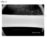
- 11 is a photograph showing a state of the silicone tube in Experimental Example 2 after alkaline water has flowed through the silicone tube shown in FIG. 10.
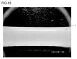
- 12 is a photograph showing the state of the silicone tube after flowing acidic water into the dialysate tube shown in FIG. 11 in Experimental Example 2.
- FIG. 1 is a circuit diagram showing a configuration of a dialysis machine cleaning system according to an embodiment of the present invention.
- the flow of the fluid at the time of performing the cleaning is indicated by an arrow extending along the circuit.
- a dialysis machine cleaning system 100 includes a dialysis machine 110, a discharge flow path 120, a three-tank electrolyzed water producing apparatus 130, and a neutralization pipe 140. Equipped with.
- the neutralization pipe 140 does not necessarily have to be provided.
- the dialyzer 110 has a dialysate circuit through which dialysate flows.
- the dialysate circuit is mainly composed of a silicone tube. Since the dialysate contains calcium carbonate, when the dialyzer 110 is operated for a long time, calcium carbonate adheres to the inner surface of the dialysate circuit.
- a dialysate preparation device 111 is connected to the dialysate circuit of the dialyzer 110.
- the dialysate preparation device 111 supplies the dialysate to the dialysis device 110.
- the dialysate circuit of the dialyzer 110 and the dialysate preparation device 111 are connected to each other via a dialysate supply channel 112.
- the dialysate supply channel 112 is composed of piping made of synthetic resin such as PFA (Perfluoroalkoxy alkane).
- PFA Perfluoroalkoxy alkane
- the dialysis machine cleaning system 100 includes a plurality of dialysis machines 110.
- the dialyzer cleaning system 100 may include only one dialyzer 110.
- Each of the plurality of dialysis machines 110 is connected to the dialysate supply channel 112 through each of the plurality of branch channels 112x corresponding to the plurality of dialysis machines 110 on a one-to-one basis.
- Each of the plurality of branch channels 112x is configured by a synthetic resin pipe.
- the dialysate preparation device 111 is connected to a first stock solution tank 113a that supplies the first stock solution to the dialysate preparation device 111.
- a second stock solution tank 113b that supplies the second stock solution to the dialysate preparation apparatus 111 is connected to the dialysate preparation apparatus 111.
- the dialysate preparation device 111 is connected to a first flowing water passage 114 for supplying raw material water to the dialysate preparation device 111.
- the dialysate preparation device 111 the dialysate is prepared by mixing the first stock solution, the second stock solution and the raw material water.
- the first stock solution is, for example, a liquid preparation prepared by dissolving calcium salt, magnesium salt, potassium salt, sodium salt and glucose in water.
- the second stock solution is a liquid preparation prepared by dissolving sodium hydrogen carbonate or the like in water.
- the raw material water is reverse osmosis water.
- the first stock solution tank 113a is connected to the dialysate preparation device 111 via a first stock solution supply channel 115a.
- the first stock solution flows through the first stock solution supply channel 115a.
- a second running water channel 116a for supplying raw material water is connected to the first stock solution tank 113a.
- the first stock solution is prepared by dissolving the powder formulation in the raw material water.
- the second stock solution tank 113b is connected to the dialysate preparation device 111 via a second stock solution supply channel 115b.
- the second stock solution flows through the second stock solution supply channel 115b.
- a third flowing water channel 116b for supplying raw material water is connected to the second stock solution tank 113b.
- the second stock solution is prepared by dissolving the powder formulation in the raw material water.
- the discharge flow path 120 is connected to the dialysate circuit of the dialyzer 110 and discharges the dialysate used in the dialyzer 110.
- the dialyzer 110 When the dialyzer 110 is operated for a long time, the biofilm, proteins and calcium carbonate contained in the used dialysate adhere to the inner surface of the discharge channel 120.
- the dialysis machine cleaning system 100 includes a plurality of discharge flow paths 120.
- the plurality of discharge flow paths 120 correspond to the plurality of dialysis machines 110 on a one-to-one basis.
- the discharge flow path 120 is composed of a synthetic resin pipe.
- the electrolyzed water producing apparatus 130 is connected to the dialysate preparation apparatus 111 via a washing pipe 150, a first pipe 151, and a first flowing water passage 114. ing.
- the first pipe 151 is branched from the cleaning pipe 150.
- the downstream side of the first pipe 151 is connected to the first flowing water channel 114.
- the electrolyzed water generator 130 is indirectly connected to the dialysate circuit of the dialyzer 110. That is, the electrolyzed water generator 130 is connected to the dialyzer 110 via the cleaning pipe 150, the first pipe 151, the first flowing water channel 114, the dialysate preparation device 111, the dialysate supply channel 112 and the branch channel 112x. It is connected.
- the electrolyzed water generator 130 may be directly connected to the dialysate circuit of the dialyzer 110.
- the electrolyzed water generator 130 is , Directly connected to the dialysate circuit of the dialyzer 110.
- the electrolyzed water generator 130 is connected to the first stock solution tank 113a via the cleaning pipe 150, the second pipe 152a, and the second flowing water passage 116a.
- the second pipe 152a is branched from the cleaning pipe 150.
- the downstream side of the second pipe 152a is connected to the second flowing water channel 116a.
- the connection mode between the electrolyzed water generator 130 and the first stock solution tank 113a is not limited to the above configuration.
- the electrolyzed water generator 130 is connected to the second stock solution tank 113b via the cleaning pipe 150, the third pipe 152b, and the third flowing water passage 116b.
- the third pipe 152b is branched from the cleaning pipe 150.
- the downstream side of the third pipe 152b is connected to the third flowing water channel 116b.
- the connection mode between the electrolyzed water generator 130 and the second stock solution tank 113b is not limited to the above configuration.
- the dialysate preparation device 111, the first stock solution tank 113a, and the second stock solution tank 113b are connected to a drainage dedicated flow path 117, a first stock solution drainage dedicated flow path 118a, and a second stock solution drainage dedicated flow path 118b, respectively. Has been done.
- dialysate preparation device 111 If an abnormality occurs in the concentration of the dialysate in the dialysate preparation device 111, or if the dialysate has been stored in the dialysate preparation device 111 for a long time, it is stored in the dialysate preparation device 111.
- the dialysate that has been discharged is discharged to the drainage-dedicated flow path 117. It should be noted that the dialysis solution or the cleaning solution may not flow in the drainage-dedicated flow path 117 during the dialysis and the cleaning described later.
- the first stock solution tank 113a is stored in the first stock solution tank 113a.
- the stored first undiluted solution is discharged to the first undiluted solution discharge dedicated channel 118a. It should be noted that the dialysis solution or the cleaning solution does not have to flow in the first stock solution drainage dedicated channel 118a during the dialysis and the cleaning described below.
- the stored second undiluted solution is discharged to the second undiluted solution drainage dedicated channel 118b. It should be noted that the dialysis solution or the cleaning solution does not have to flow in the second stock solution drainage dedicated channel 118b during the dialysis and the cleaning described below.
- the electrolyzed water generator 130 is of a three-layer type.
- FIG. 2 is a diagram showing a configuration of an electrolyzed water generator in the dialysis machine cleaning system according to the embodiment of the present invention. As shown in FIG. 2, the electrolyzed water producing apparatus 130 includes a central chamber 131, a first producing chamber 132, and a second producing chamber 133.
- the central chamber 131 and the first generation chamber 132 are partitioned by the first ion exchange membrane 132a.
- the central chamber 131 and the second generation chamber 133 are separated by the second ion exchange membrane 133a.
- the first ion exchange membrane 132a and the second ion exchange membrane 133a extend so as to face each other.
- the both ends of the central chamber 131 in the extending direction of each of the first ion exchange membrane 132a and the second ion exchange membrane 133a are connected to the circulation flow passage 134 to form an annular flow passage.
- the annular flow path formed by the central chamber 131 and the circulation flow path 134 is filled with an aqueous sodium chloride solution.
- the sodium chloride aqueous solution is flowing in one direction in the annular channel.
- a first flowing water channel 114 for supplying raw material water is connected to each of the first generation chamber 132 and the second generation chamber 133.
- the cleaning pipe 150 is connected to the first generation chamber 132.
- a neutralization pipe 140 is connected to the second generation chamber 133.
- the first insulating portion 132b is provided on the first ion exchange membrane 132a.
- a first back electrode 132c is provided on the first insulating portion 132b.
- the first back electrode 132c is arranged so as to be located inside the first generation chamber 132.
- the first back electrode 132c is provided near the first ion exchange membrane 132a.
- the second insulating portion 133b is provided on the second ion exchange membrane 133a.
- a second back electrode 133c is provided on the second insulating portion 133b.
- the second back electrode 133c is arranged so as to be located inside the second generation chamber 133.
- the second back electrode 133c is provided near the second ion exchange membrane 133a.
- the first back electrode 132c and the second back electrode 133c are connected to each other via a DC power supply 135.
- the DC power supply 135 can apply the voltage of the anode to the first back electrode 132c and the voltage of the cathode to the second back electrode 133c.
- the DC power supply 135 is configured to be able to reverse the direction of voltage application. Accordingly, the DC power supply 135 can apply the voltage of the cathode to the first back electrode 132c and the voltage of the anode to the second back electrode 133c.
- chloride ions in the central chamber 131 pass through the first ion exchange membrane 132a and move to the first generation chamber 132.
- Chloride is generated by the chloride ions being oxidized on the surface of the first back electrode 132c.
- acidic water that is an aqueous solution in which hypochlorous acid is dissolved is generated.
- the acidic water flows into the cleaning pipe 150 as a cleaning liquid.
- the cleaning liquid flows from the cleaning pipe 150 to each of the first pipe 151, the second pipe 152a, and the third pipe 152b.
- the cleaning liquid that has flowed into the first pipe 151 flows through the first flowing water channel 114, the dialysate preparation apparatus 111, the dialysate supply channel 112, the branch channel 112x, the dialysate circuit of the dialyzer 110, and the discharge channel 120 in this order.
- the cleaning liquid that has flowed into the second pipe 152a is the second flowing water channel 116a, the first stock solution tank 113a, the first stock solution supply flow path 115a, the dialysate preparation device 111, the dialysate supply flow path 112, the branch flow path 112x, and the dialyzer. It flows through the dialysate circuit 110 and the discharge flow path 120 in this order.
- the cleaning liquid that has flowed into the third pipe 152b has a third flowing water channel 116b, a second stock solution tank 113b, a second stock solution supply flow path 115b, a dialysate preparation device 111, a dialysate supply flow path 112, a branch flow path 112x, and a dialyzer. It flows through the dialysate circuit 110 and the discharge flow path 120 in this order.
- the sodium ions in the central chamber 131 pass through the second ion exchange membrane 133a and move to the second generation chamber 133.
- the hydrogen ions in the raw material water are reduced to generate hydrogen, thereby generating hydroxide ions.
- alkaline water which is an aqueous solution containing hydroxide ions, is generated.
- the alkaline water flows into the neutralization pipe 140 as a neutralizing liquid.
- the DC power supply 135 applies the voltage of the cathode to the first back electrode 132c and the voltage of the anode to the second back electrode 133c.
- the electrolyzed water producing apparatus 130 produces each of acidic water and alkaline water. Further, in the dialysis machine cleaning system 100 according to the present embodiment, by changing the application direction of the voltage of the DC power supply 135, each of the dialysate circuit of the dialysis machine 110 and the discharge flow path 120 from the electrolyzed water producing apparatus 130. Then, acidic water and alkaline water are alternately flowed as a cleaning liquid.
- the method of alternately flowing acidic water and alkaline water from the electrolyzed water generator 130 is not limited to the method of changing the voltage application direction of the DC power supply 135.
- the electrolytic water generator 130 may be provided with an additional pipe and a plurality of valves, and the opening and closing of each of the plurality of valves may be controlled to alternately flow the acidic water and the alkaline water as the cleaning liquid.
- the electrolyzed water generating apparatus 130, the dialysis fluid circuit of the dialysis machine 110 and each of the discharge flow path 120 are at least once acidic. After the water has been flushed, the alkaline water is flushed.
- the dialysis machine cleaning system 100 it is preferable to flow alkaline water as the last cleaning liquid. As a result, it is possible to suppress the acidic water from remaining in the discharge flow path 120 due to the alkaline water flowing after the acidic water flows, and suppress deterioration of the dialysate circuit and the discharge flow path 120 due to the acidic water. be able to.
- the electrolyzed water generator 130 operates as described above, the electrolyte such as sodium chloride contained in the aqueous solution with which the central chamber 131 is filled does not mix with the cleaning liquid.
- the electrolyzed water generator 130 is configured to be able to control the pH value of each of the acidic water and the alkaline water.
- the pH value of each of the acidic water and the alkaline water is adjusted, for example, by the density of the current from the DC power supply 135, the energization time of the DC power supply 135, the flow rate of the sodium chloride aqueous solution in the circulation flow path 134, and the dissolved concentration of sodium chloride in the aqueous solution. It can be controlled by In the dialyzer cleaning system 100 according to the present embodiment, the pH value of the acidic water is controlled to be 3.0 or more and 3.7 or less when the acidic water is flown as the cleaning liquid.
- the neutralization pipe 140 is connected to the electrolyzed water generator 130. As described above, the neutralization pipe 140 discharges the neutralizing liquid that is not the cleaning liquid among the acidic water and the alkaline water generated in the electrolytic water generating device 130.
- the dialysis machine cleaning system further includes a neutralization tank 160, as shown in FIG.
- the downstream side of each of the plurality of discharge channels 120 is connected to the neutralization tank 160.
- the downstream side of the neutralization pipe 140 is connected to the neutralization tank 160.
- each of the cleaning liquid and the neutralizing liquid flows into the neutralization tank 160.
- the neutralization pipe 140 is configured such that the neutralization liquid discharged from the neutralization pipe 140 joins with the cleaning liquid discharged from the discharge passage 120.
- the neutralizing liquid When using acidic water as the cleaning liquid, the neutralizing liquid is alkaline water. When alkaline water is used as the cleaning liquid, the neutralizing liquid is acidic water. Therefore, in the neutralization tank 160, whether the cleaning liquid is acidic water or alkaline water is neutralized by the neutralizing liquid. The cleaning liquid is neutralized in the neutralization tank 160 and then discharged from the neutralization tank 160.
- downstream side of the drainage dedicated flow path 117 is also connected to the neutralization tank 160.
- the dialysate in the dialysate preparation device 111 is discharged, the dialysate flows into the neutralization tank 160 via the drainage dedicated flow path 117.
- the dialysate preparation device 111 may be washed with the above washing liquid after the dialysate preparation device 111 is drained.
- the cleaning liquid used for cleaning is discharged into the neutralization tank 160 via the drainage-dedicated flow path 117 to discharge the cleaning liquid.
- the downstream side of the first undiluted liquid discharge channel 118a is also connected to the neutralization tank 160.
- the first undiluted solution in the first undiluted solution tank 113a is discharged, the first undiluted solution flows into the neutralization tank 160 via the first undiluted solution drainage dedicated channel 118a.
- the first stock solution tank 113a may be washed with the above-mentioned cleaning solution after the first stock solution in the first stock solution tank 113a is discharged.
- the cleaning liquid used for cleaning is discharged into the neutralization tank 160 via the first stock solution discharge-only channel 118a to discharge the cleaning liquid.
- the downstream side of the second undiluted liquid discharge channel 118b is also connected to the neutralization tank 160.
- the second undiluted solution in the second undiluted solution tank 113b is discharged, the second undiluted solution flows into the neutralization tank 160 via the second undiluted solution drainage dedicated channel 118b.
- the second stock solution tank 113b may be washed with the above-mentioned cleaning solution after the second stock solution in the second stock solution tank 113b is discharged.
- the cleaning liquid used for cleaning is discharged into the neutralization tank 160 via the second undiluted liquid discharge channel 118b to discharge the cleaning liquid.
- FIG. 3 is a photograph showing the state of the silicone tube before the cleaning liquid flows in Experimental Example 1.
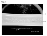
- FIG. 4 is a photograph showing the state of the silicone tube in Experimental Example 1 after acidic water has flowed through the silicone tube shown in FIG.
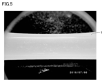
- FIG. 5 is a photograph showing the state of the silicone tube after the alkaline water flowed through the dialysate tube shown in FIG. 4 in Experimental Example 1.
- FIG. 6 is a photograph showing the state of the silicone tube in Experimental Example 1 after acidic water has flowed through the silicone tube shown in FIG.
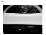
- FIG. 7 is a photograph showing the state of the silicone tube after the alkaline water flowed through the dialysate tube shown in FIG. 6 in Experimental Example 1.
- a silicone tube 1 having a deposit 2 such as protein and calcium carbonate attached to the inner surface was prepared.
- the deposit 2 was attached by pouring the dialysate after use into a new silicone tube in a dialysis machine.
- the silicone tube 1 of FIG. 3 is connected to a three-tank electrolyzed water generator, and acidic water having a pH value of 3.0 and a concentration of 50 ppm is passed through the silicone tube 1 as the first washing step.
- the flow rate of the acidic water was 0.5 L/min, and the flow time was 2.5 hours.
- alkaline water having a pH value of 11.0 and a concentration of 50 ppm was passed through the silicone tube 1 of FIG.
- the flow rate of the alkaline water was 0.5 L/min, and the flow time was 2 hours.
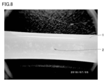
- FIG. 8 is a photograph showing the state of the silicone tube before the cleaning liquid flows in Experimental Example 2.
- FIG. 9 is a photograph showing the state of the silicone tube in Experimental Example 2 after the alkaline water has flowed through the silicone tube shown in FIG.
- FIG. 10 is a photograph showing the state of the silicone tube after flowing acidic water through the dialysate tube shown in FIG. 9 in Experimental Example 2.
- FIG. 11 is a photograph showing the state of the silicone tube in Experimental Example 2 after the alkaline water has flowed through the silicone tube shown in FIG. 10.
- FIG. 12 is a photograph showing the state of the silicone tube after flowing acidic water through the dialysate tube shown in FIG. 11 in Experimental Example 2.
- a silicone tube 1 having a deposit 2 such as protein and calcium carbonate attached to the inner surface was prepared.
- the deposit 2 was attached by pouring the dialysate after use into a new silicone tube in a dialysis machine.
- the silicone tube 1 of FIG. 8 was connected to a three-tank electrolyzed water generator, and as the first washing step, alkaline water having a pH value of 11.0 and a concentration of 50 ppm was passed through the silicone tube 1.
- the flow rate of the alkaline water was 0.5 L/min, and the flow time was 2.5 hours.
- acidic water and alkaline water are supplied from the electrolyzed water generator 130 to the dialysate circuit of the dialyzer 110 and the discharge flow path 120, respectively.
- the electrolyzed water generator 130 is a three-tank type.
- the pH value of the acidic water is 3.0 or more and 3.7 or less.
- hypochlorous acid dissolved in the acidic water may be decomposed to generate chlorine gas.
- generation of chlorine gas can be suppressed while maintaining a high cleaning effect of the acidic water.
- dialyzer cleaning system 100 acidic water is flowed from the electrolyzed water generator 130 to each of the dialysate circuit of the dialyzer 110 and the discharge flow path 120 at least once. After that, alkaline water is washed away. As a result, each of the dialysate circuit of the dialyzer 110 and the discharge flow path 120 can be effectively cleaned using the cleaning liquid generated by the electrolyzed water generator 130.
- the dialysis machine cleaning system 100 is configured such that the neutralization liquid discharged from the neutralization pipe 140 joins with the cleaning liquid discharged from the discharge passage 120. This eliminates the need for a neutralizing agent for neutralizing the cleaning liquid and for eliminating the need for a tank for storing the neutralizing agent, thus saving space in the dialysis machine cleaning system 100.
- 1 silicone tube, 2 deposits, 7 JP Heihei, 100 dialysis machine cleaning system, 110 dialysis machine, 111 dialysis solution preparation device, 112 dialysis solution supply channel, 112x branch channel, 113a first stock solution tank, 113b second stock solution Tank, 114 1st flowing water channel, 115a 1st undiluted solution supply flow path, 115b 2nd undiluted solution supplying flow path, 116a 2nd flowing water path, 116b 3rd flowing water path, 117 dedicated drainage channel, 118a 1st undiluted solution Flow passage, 118b Second flow passage for exclusive use of waste liquid, 120 discharge flow passage, 130 electrolyzed water generator, 131 central chamber, 132 first generation chamber, 132a first ion exchange membrane, 132b first insulating part, 132c first Back electrode, 133 second generation chamber, 133a second ion exchange membrane, 133b second insulating part, 133c second back electrode, 134 circulation flow path, 135 DC power supply, 140 neutralization pipe,
Landscapes
- Health & Medical Sciences (AREA)
- Engineering & Computer Science (AREA)
- Chemical & Material Sciences (AREA)
- Urology & Nephrology (AREA)
- Water Supply & Treatment (AREA)
- Chemical Kinetics & Catalysis (AREA)
- Life Sciences & Earth Sciences (AREA)
- Heart & Thoracic Surgery (AREA)
- Biomedical Technology (AREA)
- General Health & Medical Sciences (AREA)
- Organic Chemistry (AREA)
- Veterinary Medicine (AREA)
- Public Health (AREA)
- Animal Behavior & Ethology (AREA)
- Hematology (AREA)
- Anesthesiology (AREA)
- Vascular Medicine (AREA)
- Emergency Medicine (AREA)
- Oil, Petroleum & Natural Gas (AREA)
- Wood Science & Technology (AREA)
- Environmental & Geological Engineering (AREA)
- Hydrology & Water Resources (AREA)
- Inorganic Chemistry (AREA)
- General Chemical & Material Sciences (AREA)
- Electrochemistry (AREA)
- Molecular Biology (AREA)
- Analytical Chemistry (AREA)
- External Artificial Organs (AREA)
- Water Treatment By Electricity Or Magnetism (AREA)
- Detergent Compositions (AREA)
Abstract
透析装置洗浄システム(100)は、透析装置(110)と、排出流路(120)と、三槽式の電解水生成装置(130)とを備えている。透析装置(110)は、透析液が流れる透析液回路を有している。排出流路(120)は、透析装置(110)の透析液回路に接続され、透析装置(110)で使用された透析液を排出する。電解水生成装置(130)は、透析装置(110)の透析液回路に直接的または間接的に接続され、酸性水およびアルカリ性水の各々を生成する。電解水生成装置(130)から、透析液回路および排出流路(120)の各々に、酸性水およびアルカリ性水が交互に洗浄液として流される。
Description
本発明は、透析装置洗浄システムに関する。
透析装置洗浄システムの構成を開示した先行文献として、特開平7-284744号公報(特許文献1)がある。特許文献1に記載された透析装置洗浄システムにおいては、アルカリ性電解水と酸性電解水とを、電解水生成器にて生成する。電解水生成器は、いわゆる連続通水式であって、純水を収容する電解槽を有しており、電解槽内は隔膜によって陰極室と陽極室とに区画されている。生成される電解水のpH値は、塩化ナトリウム(NaCl)などの電解質の添加量などによって調節される。透析を終了して透析装置の洗浄を行なう場合には、アルカリ性電解水、純水および酸性電解水が中央供給装置に順次送られる。これらの流体は、さらにこの中央供給装置から患者監視装置に送られる。
従来の透析装置洗浄システムにおいては、電解水生成装置の電解槽に、塩化ナトリウムなどの電解質が添加される。電解水生成装置で洗浄液として生成された酸性水またはアルカリ性水に、塩化ナトリウムなどの電解質が含まれている場合、当該洗浄液が配管を腐食させるおそれがある。
本発明は上記の問題点に鑑みてなされたものであって、洗浄液による配管の腐食を抑制できる、透析装置洗浄システムを提供することを目的とする。
本発明に基づく透析装置洗浄システムは、透析装置と、排出流路と、三槽式の電解水生成装置とを備えている。透析装置は、透析液が流れる透析液回路を有している。排出流路は、透析装置の透析液回路に接続され、透析装置で使用された透析液を排出する。三槽式の電解水生成装置は、透析装置の透析液回路に直接的または間接的に接続され、酸性水およびアルカリ性水の各々を生成する。透析装置洗浄システムにおいては、電解水生成装置から、透析液回路および排出流路の各々に、酸性水およびアルカリ性水が交互に洗浄液として流される。
本発明の一形態においては、酸性水のpH値が3.0以上3.7以下である。
本発明の一形態においては、電解水生成装置から、透析液回路および排出流路の各々に、少なくとも1回は、酸性水が流されたあと、アルカリ性水が流される。
本発明の一形態においては、電解水生成装置から、透析液回路および排出流路の各々に、少なくとも1回は、酸性水が流されたあと、アルカリ性水が流される。
本発明の一形態においては、透析装置洗浄システムが、中和用配管をさらに備えている。中和用配管は、電解水生成装置に接続され、電解水生成装置において生成された酸性水およびアルカリ性水のうち洗浄液ではない方の中和用液を排出する。中和用配管は、中和用配管から排出された中和用液が、排出流路から排出された洗浄液と合流するように構成されている。
本発明によれば、透析装置洗浄システムにおいて、洗浄液による配管の腐食を抑制することができる。
以下、本発明の一実施形態に係る透析装置洗浄システムについて図面を参照して説明する。以下の実施形態の説明においては、図中の同一または相当部分には同一符号を付して、その説明は繰り返さない。
図1は、本発明の一実施形態に係る透析装置洗浄システムの構成を示す回路図である。図1においては、洗浄実施時における流体の流れを、回路に沿って延びる矢印で示している。
図1に示すように、本発明の一実施形態に係る透析装置洗浄システム100は、透析装置110と、排出流路120と、三槽式の電解水生成装置130と、中和用配管140とを備えている。なお、中和用配管140は、必ずしも設けられていなくてもよい。
透析装置110は、透析液が流れる透析液回路を有している。本実施形態において、透析液回路は、主にシリコーンチューブで構成されている。透析液には炭酸カルシウムが含まれているため、透析装置110を長時間稼働させると、透析液回路の内面に、炭酸カルシウムが付着する。
本実施形態において、透析装置110の透析液回路には、透析液調製装置111が接続されている。透析装置110による透析を実施する際に、透析液調製装置111は、透析液を透析装置110に供給する。透析装置110の透析液回路および透析液調製装置111は、透析液供給流路112を介して互いに接続されている。
本実施形態において、透析液供給流路112は、PFA(Perfluoroalkoxy alkane)などの合成樹脂製の配管で構成されている。透析装置110を長時間稼働させると、透析液供給流路112の内面に、炭酸カルシウムが付着する。
図1に示すように、本実施形態においては、透析装置洗浄システム100が、複数の透析装置110を備えている。ただし、透析装置洗浄システム100は、1つの透析装置110のみを備えていてもよい。
複数の透析装置110の各々は、複数の透析装置110と1対1で対応する複数の分岐流路112xの各々を介して、透析液供給流路112と互いに接続されている。複数の分岐流路112xの各々は、合成樹脂製の配管で構成されている。透析装置110を長時間稼働させると、複数の分岐流路112xの各々の内面に、炭酸カルシウムが付着する。
透析液調製装置111には、透析液調製装置111に第1原液を供給する第1原液タンク113aが接続されている。透析液調製装置111には、透析液調製装置111に第2原液を供給する第2原液タンク113bが接続されている。透析液調製装置111には、透析液調製装置111に原料水を供給する第1流水路114が接続されている。
透析液調製装置111において、第1原液、第2原液および原料水が混合されることにより、透析液が調製される。第1原液は、たとえば、カルシウム塩、マグネシウム塩、カリウム塩、ナトリウム塩およびブドウ糖などが水に溶解することにより調製された液体製剤である。第2原液は、炭酸水素ナトリウムなどが水に溶解することにより調製された液体製剤である。本実施形態において、原料水は逆浸透水である。
第1原液タンク113aは、第1原液供給流路115aを介して透析液調製装置111と互いに接続されている。第1原液供給流路115aには、第1原液が流れる。
第1原液タンク113aには、原料水を供給する第2流水路116aが接続されている。第1原液タンク113aにおいて、原料水に粉末製剤が溶解することにより、第1原液が調製される。
第2原液タンク113bは、第2原液供給流路115bを介して透析液調製装置111と互いに接続されている。第2原液供給流路115bには、第2原液が流れる。
第2原液タンク113bには、原料水を供給する第3流水路116bが接続されている。第2原液タンク113bにおいて、原料水に粉末製剤が溶解することにより、第2原液が調製される。
排出流路120は、透析装置110の透析液回路に接続され、透析装置110で使用された透析液を排出する。透析装置110を長時間稼働させると、排出流路120の内面には、バイオフィルム、並びに、使用された透析液に含まれる蛋白および炭酸カルシウムなどが付着する。
本実施形態において、透析装置洗浄システム100は、複数の排出流路120を備えている。複数の排出流路120は、複数の透析装置110に1対1で対応している。本実施形態において、排出流路120は、合成樹脂製の配管で構成されている。
図1に示すように、本実施形態において、電解水生成装置130は、洗浄用配管150と、第1配管151と、第1流水路114とを介して、透析液調製装置111と互いに接続されている。
第1配管151は洗浄用配管150から分岐している。第1配管151の下流側は、第1流水路114と互いに接続されている。
このように、本実施形態において、電解水生成装置130は、透析装置110の透析液回路に間接的に接続されている。すなわち、電解水生成装置130は、洗浄用配管150、第1配管151、第1流水路114、透析液調製装置111、透析液供給流路112および分岐流路112xを介して、透析装置110に接続されている。
なお、電解水生成装置130は、透析装置110の透析液回路に直接的に接続されてもよい。たとえば、透析装置洗浄システム100において透析液調製装置111が設けられておらず、透析装置110の透析液回路が透析液を調製する調製部を有している場合には、電解水生成装置130は、透析装置110の透析液回路に直接的に接続される。
本実施形態において、電解水生成装置130は、洗浄用配管150と、第2配管152aと、第2流水路116aとを介して、第1原液タンク113aと互いに接続されている。
第2配管152aは、洗浄用配管150から分岐している。第2配管152aの下流側は、第2流水路116aと互いに接続されている。なお、電解水生成装置130と第1原液タンク113aとの接続態様は、上記の構成に限定されない。
本実施形態において、電解水生成装置130は、洗浄用配管150と、第3配管152bと、第3流水路116bとを介して、第2原液タンク113bと互いに接続されている。
第3配管152bは、洗浄用配管150から分岐している。第3配管152bの下流側は、第3流水路116bと互いに接続されている。なお、電解水生成装置130と第2原液タンク113bとの接続態様は、上記の構成に限定されない。
透析液調製装置111、第1原液タンク113aおよび第2原液タンク113bには、それぞれ、排液専用流路117、第1原液排液専用流路118aおよび第2原液排液専用流路118bが接続されている。
透析液調製装置111内において、透析液の濃度に異常が発生した場合、または、透析液が透析液調製装置111内に長時間貯留されていた場合には、透析液調製装置111内に貯留されている透析液が、排液専用流路117に排出される。なお、透析実施時および後述する洗浄を実施する際は、排液専用流路117に透析液または洗浄液が流れていなくてもよい。
第1原液タンク113a内において、第1原液の濃度に異常が発生した場合、または、第1原液が第1原液タンク113a内に長時間貯留されていた場合には、第1原液タンク113a内に貯留されている第1原液が、第1原液排液専用流路118aへ排出される。なお、透析実施時および後述する洗浄を実施する際は、第1原液排液専用流路118aに透析液または洗浄液が流れていなくてもよい。
第2原液タンク113b内において、第2原液の濃度に異常が発生した場合、または、第2原液が第2原液タンク113b内に長時間貯留されていた場合には、第2原液タンク113b内に貯留されている第2原液が、第2原液排液専用流路118bへ排出される。なお、透析実施時および後述する洗浄を実施する際は、第2原液排液専用流路118bに透析液または洗浄液が流れていなくてもよい。
本実施形態において、電解水生成装置130は、三層式である。図2は、本発明の一実施形態に係る透析装置洗浄システムにおける、電解水生成装置の構成を示す図である。図2に示すように、電解水生成装置130は、中央室131と、第1生成室132と、第2生成室133とを含んでいる。
中央室131と、第1生成室132とは、第1イオン交換膜132aで仕切られている。中央室131と、第2生成室133とは、第2イオン交換膜133aで仕切られている。第1イオン交換膜132aおよび第2イオン交換膜133aは、互いに対向するように延在している。
第1イオン交換膜132aおよび第2イオン交換膜133aの各々の延在方向における中央室131の両端部が、循環流路134と互いに接続されることにより、環状流路が構成されている。中央室131および循環流路134で構成される環状流路には、塩化ナトリウム水溶液が充填されている。塩化ナトリウム水溶液は、当該環状流路において一方向に流れている。
第1生成室132および第2生成室133の各々には、原料水を供給する第1流水路114が接続されている。第1生成室132には、洗浄用配管150が接続されている。第2生成室133には、中和用配管140が接続されている。
第1イオン交換膜132aには、第1絶縁部132bが設けられている。第1絶縁部132bには、第1背面電極132cが設けられている。
第1背面電極132cは、第1生成室132内に位置するように配置されている。第1背面電極132cは、第1イオン交換膜132a近傍に設けられる。
第2イオン交換膜133aには、第2絶縁部133bが設けられている。第2絶縁部133bには、第2背面電極133cが設けられている。
第2背面電極133cは、第2生成室133内に位置するように配置されている。第2背面電極133cは、第2イオン交換膜133a近傍に設けられている。
第1背面電極132cと、第2背面電極133cとは、直流電源135を介して互いに接続されている。直流電源135は、第1背面電極132cに陽極の電圧を印加するとともに、第2背面電極133cに陰極の電圧を印加することが可能である。
直流電源135は、電圧の印加方向を反転可能に構成されている。これにより、直流電源135は、第1背面電極132cに陰極の電圧を印加するとともに、第2背面電極133cに陽極の電圧を印加することも可能である。
以下、本実施形態における三層式の電解水生成装置130による洗浄液の生成動作について説明する。
まず、直流電源135が、第1背面電極132cに陽極の電圧を印加するとともに、第2背面電極133cに陰極の電圧を印加した場合について説明する。
この場合、中央室131中の塩化物イオンは、第1イオン交換膜132aを通過して、第1生成室132に移動する。塩化物イオンが第1背面電極132cの表面で酸化されることにより、塩素が生成される。塩素が第1生成室132中の原料水と反応することにより、次亜塩素酸が溶解した水溶液である酸性水が生成される。酸性水は、洗浄液として洗浄用配管150に流入する。
図1に示すように、本実施形態において、洗浄液は、洗浄用配管150から、第1配管151、第2配管152aおよび第3配管152bの各々に流れる。第1配管151に流入した洗浄液は、第1流水路114、透析液調製装置111、透析液供給流路112、分岐流路112x、透析装置110の透析液回路および排出流路120をこの順で流れる。
第2配管152aに流入した洗浄液は、第2流水路116a、第1原液タンク113a、第1原液供給流路115a、透析液調製装置111、透析液供給流路112、分岐流路112x、透析装置110の透析液回路および排出流路120をこの順で流れる。
第3配管152bに流入した洗浄液は、第3流水路116b、第2原液タンク113b、第2原液供給流路115b、透析液調製装置111、透析液供給流路112、分岐流路112x、透析装置110の透析液回路および排出流路120をこの順で流れる。
図2に示すように、中央室131中のナトリウムイオンは、第2イオン交換膜133aを通過して、第2生成室133に移動する。第2背面電極133cの表面では、原料水中の水素イオンが還元されて水素が生成することにより、水酸化物イオンが生成される。これにより、水酸化物イオンを含む水溶液であるアルカリ性水が生成される。アルカリ性水は、中和用液として中和用配管140に流入する。
次に、直流電源の電圧印加方向を反転させた場合について説明する。この場合、直流電源135が、第1背面電極132cに陰極の電圧を印加するとともに、第2背面電極133cに陽極の電圧を印加する。
これにより、第1生成室132および第2生成室133の各々において生じる反応も互いに入れ替わる。すなわち、第1生成室132においてアルカリ性水が生成される。このアルカリ性水が、洗浄液として洗浄用配管150に流入する。第2生成室133においては酸性水が生成される。この酸性水が、中和用液として中和用配管140に流入する。
このようにして、電解水生成装置130は、酸性水およびアルカリ性水の各々を生成する。また、本実施形態に係る透析装置洗浄システム100においては、直流電源135の電圧の印加方向を変更することにより、電解水生成装置130から、透析装置110の透析液回路および排出流路120の各々に、酸性水およびアルカリ性水が交互に洗浄液として流される。
なお、電解水生成装置130から、酸性水およびアルカリ性水を交互に流す方法は、直流電源135の電圧の印加方向を変更する方法に限定されない。電解水生成装置130に追加の配管および複数のバルブを設け、当該複数のバルブの各々の開閉を制御することにより、酸性水およびアルカリ性水を交互に洗浄液として流してもよい。
本実施形態に係る透析装置洗浄システム100においては、後述する洗浄効果の観点から、電解水生成装置130から、透析装置110の透析液回路および排出流路120の各々に、少なくとも1回は、酸性水が流されたあと、アルカリ性水が流される。
本実施形態に係る透析装置洗浄システム100においては、最後の洗浄液としてアルカリ性水を流すことが好ましい。これにより、酸性水が流れたあと、アルカリ性水が流れることで酸性水が排出流路120内に残留することを抑制でき、酸性水による透析液回路および排出流路120の各々の劣化を抑制することができる。
また、電解水生成装置130は上記のように動作するため、中央室131に充填された水溶液に含まれる塩化ナトリウムなどの電解質は、洗浄液に混入することがない。
本実施形態において、電解水生成装置130は、酸性水およびアルカリ性水の各々のpH値を制御可能に構成されている。酸性水およびアルカリ性水の各々のpH値は、たとえば、直流電源135による電流の密度、直流電源135の通電時間、循環流路134における塩化ナトリウム水溶液の流量、当該水溶液における塩化ナトリウムの溶解濃度を調節することによって制御することができる。本実施形態に係る透析装置洗浄システム100においては、洗浄液として酸性水を流すときに、酸性水のpH値が3.0以上3.7以下となるように制御される。
図1に示すように、中和用配管140は、電解水生成装置130に接続されている。中和用配管140は、上述したように、電解水生成装置130において生成された酸性水およびアルカリ性水のうち洗浄液ではない方の中和用液を排出する。
本実施形態に係る透析装置洗浄システムは、図1に示すように、中和槽160をさらに備えている。複数の排出流路120の各々の下流側は、中和槽160と互いに接続されている。中和用配管140の下流側は、中和槽160と互いに接続されている。
すなわち、中和槽160には洗浄液および中和用液の各々が流入する。このように、中和用配管140は、中和用配管140から排出された中和用液が、排出流路120から排出された洗浄液と合流するように構成されている。
洗浄液として酸性水を使用しているとき、中和用液はアルカリ性水である。また、洗浄液としてアルカリ性水を使用しているとき、中和用液は酸性水である。このため、中和槽160内においては、洗浄液が酸性水またはアルカリ性水のいずれであっても、中和用液によって中和される。洗浄液は、中和槽160で中和された後、中和槽160から排出される。
さらに、排液専用流路117の下流側も、中和槽160と互いに接続されている。透析液調製装置111内における透析液が排出される際には、透析液が、排液専用流路117を経由して、中和槽160に流入する。
なお、透析液調製装置111内における透析液を排出させたあと、透析液調製装置111を上記洗浄液で洗浄してもよい。この場合、排液専用流路117を経由して、洗浄に使用した洗浄液を中和槽160に流入させることで、洗浄液を排出する。
第1原液排液専用流路118aの下流側も、中和槽160と互いに接続されている。第1原液タンク113a内における第1原液が排出される際には、第1原液が、第1原液排液専用流路118aを経由して、中和槽160に流入する。
なお、第1原液タンク113a内における第1原液を排出させたあと、第1原液タンク113aを上記洗浄液で洗浄してもよい。この場合、第1原液排液専用流路118aを経由して、洗浄に使用した洗浄液を中和槽160に流入させることで、洗浄液を排出する。
第2原液排液専用流路118bの下流側も、中和槽160と互いに接続されている。第2原液タンク113b内における第2原液が排出される際には、第2原液が、第2原液排液専用流路118bを経由して、中和槽160に流入する。
なお、第2原液タンク113b内における第2原液を排出させたあと、第2原液タンク113bを上記洗浄液で洗浄してもよい。この場合、第2原液排液専用流路118bを経由して、洗浄に使用した洗浄液を中和槽160に流入させることで、洗浄液を排出する。
(実験例1)
ここで、酸性水およびアルカリ性水を交互に流すことによる洗浄効果を確認した、実験例について説明する。
ここで、酸性水およびアルカリ性水を交互に流すことによる洗浄効果を確認した、実験例について説明する。
実験例1においては、1回目の洗浄工程において酸性水が流れ、2回目の洗浄工程においてアルカリ性水が流れ、3回目の洗浄工程において酸性水が流れ、4回目の洗浄工程においてアルカリ性水が流れたときの洗浄効果を確認した。
図3は、実験例1において、洗浄液が流れる前のシリコーンチューブの状態を示した写真である。図4は、実験例1において、図3に示したシリコーンチューブに酸性水が流れたあとのシリコーンチューブの状態を示した写真である。図5は、実験例1において、図4に示した透析液チューブにアルカリ性水が流れたあとのシリコーンチューブの状態を示した写真である。図6は、実験例1において、図5に示したシリコーンチューブに酸性水が流れたあとのシリコーンチューブの状態を示した写真である。図7は、実験例1において、図6に示した透析液チューブにアルカリ性水が流れたあとのシリコーンチューブの状態を示した写真である。
図3に示すように、実験例1においては、蛋白および炭酸カルシウムなどの付着物2が内面に付着したシリコーンチューブ1を用意した。付着物2については、透析装置にて使用後の透析液を新品のシリコーンチューブに流すことにより付着させた。
次に、図3のシリコーンチューブ1を三槽式の電解水生成装置に接続し、1回目の洗浄工程として、シリコーンチューブ1に、pH値が3.0、濃度が50ppmの酸性水を通流させた。酸性水の流量は0.5L/min、通流時間は2.5時間とした。
図4に示すように、酸性水のみをシリコーンチューブ1に通流させた段階では、シリコーンチューブ1内の付着物2の付着量の低減は、目視で確認できなかった。
次に、2回目の洗浄工程として、図4のシリコーンチューブ1に、pH値が11.0、濃度が50ppmのアルカリ性水を通流させた。アルカリ性水の流量は0.5L/min、通流時間は2時間とした。
図5に示すように、酸性水を通流させたあと、さらにアルカリ性水をシリコーンチューブに通流させたことで、シリコーンチューブ1内の付着物2の付着量が十分に低減されたことを目視で確認できた。
次に、3回目の洗浄工程として、通流時間を2時間としたこと以外は、実験例1の1回目の洗浄工程の条件と同様にして、酸性水をシリコーンチューブ1に通流させた。図6に示すように、シリコーンチューブ1内において新たな付着物は発生しなかった。
次に、4回目の洗浄工程として、実験例1の2回目の洗浄工程の条件と同様にしてアルカリ性水をシリコーンチューブ1に通流させた。図7に示すように、シリコーンチューブ1内において新たな付着物は発生しなかった。
(実験例2)
次に、実験例2について説明する。実験例2においては、1回目の洗浄工程においてアルカリ性水が流れ、2回目の洗浄工程において酸性水が流れ、3回目の洗浄工程においてアルカリ性水が流れ、4回目の洗浄工程において酸性水が流れたときの洗浄効果を確認した。
次に、実験例2について説明する。実験例2においては、1回目の洗浄工程においてアルカリ性水が流れ、2回目の洗浄工程において酸性水が流れ、3回目の洗浄工程においてアルカリ性水が流れ、4回目の洗浄工程において酸性水が流れたときの洗浄効果を確認した。
図8は、実験例2において、洗浄液が流れる前のシリコーンチューブの状態を示した写真である。図9は、実験例2において、図8に示したシリコーンチューブにアルカリ性水が流れたあとのシリコーンチューブの状態を示した写真である。図10は、実験例2において、図9に示した透析液チューブに酸性水が流れたあとのシリコーンチューブの状態を示した写真である。図11は、実験例2において、図10に示したシリコーンチューブにアルカリ性水が流れたあとのシリコーンチューブの状態を示した写真である。図12は、実験例2において、図11に示した透析液チューブに酸性水が流れたあとのシリコーンチューブの状態を示した写真である。
図8に示すように、実験例2においては、蛋白および炭酸カルシウムなどの付着物2が内面に付着したシリコーンチューブ1を用意した。付着物2については、透析装置にて使用後の透析液を新品のシリコーンチューブに流すことにより付着させた。
次に、図8のシリコーンチューブ1を三槽式の電解水生成装置に接続し、1回目の洗浄工程として、シリコーンチューブ1に、pH値が11.0、濃度が50ppmのアルカリ性水を通流させた。アルカリ性水の流量は0.5L/min、通流時間は2.5時間とした。
図9に示すように、アルカリ性水のみをシリコーンチューブ1に通流させた段階で、シリコーンチューブ1内の付着物2の付着量が、わずかに低減されたことを目視で確認できた。
次に、2回目の洗浄工程として、図4のシリコーンチューブ1に、pH値が3.0、濃度が50ppmの酸性水を通流させた。酸性水の流量は0.5L/min、通流時間は2時間とした。
図10に示すように、アルカリ性水を通流させたあと、さらに酸性水をシリコーンチューブ1に通流させると、シリコーンチューブ1内の付着物2に含まれる蛋白が凝集したことが目視で確認できた。
次に、3回目の洗浄工程として、通流時間を2時間としたこと以外は、実験例2の1回目の洗浄工程の条件と同様にして、アルカリ性水をシリコーンチューブ1に通流させた。図11に示すように、シリコーンチューブ1内の付着物2の付着量が十分に低減されたことを目視で確認できた。
次に、4回目の洗浄工程として、実験例2の2回目の洗浄工程の条件と同様にして酸性水をシリコーンチューブ1に通流させた。図12に示すように、シリコーンチューブ1内において新たな付着物は発生しなかった。
このように、本実験例においては、酸性水およびアルカリ性水が交互に流されることにより、シリコーンチューブ1内の付着物が十分に低減されることが確認できた。特に、酸性水が流されたあと、アルカリ性水が流されることにより、シリコーンチューブ1内の付着物が効果的に低減されることが確認できた。
上記のように、本発明の一実施形態に係る透析装置洗浄システム100においては、電解水生成装置130から、透析装置110の透析液回路および排出流路120の各々に、酸性水およびアルカリ性水が交互に流される。電解水生成装置130は、三槽式である。これにより、透析装置110の透析液回路および排出流路120の各々を洗浄することができるとともに、洗浄液に塩化ナトリウムなどの電解質が含まれないため、洗浄液による配管の腐食を抑制できる。
本発明の一実施形態に係る透析装置洗浄システム100においては、酸性水のpH値が3.0以上3.7以下である。酸性水のpH値が3.0未満である場合、酸性水に溶解している次亜塩素酸が分解して塩素ガスが発生する可能性がある。酸性水のpH値が3.0以上3.7以下であることにより、酸性水による洗浄効果を高く維持しつつ、塩素ガスの発生を抑制することができる。
本発明の一実施形態に係る透析装置洗浄システム100においては、電解水生成装置130から、透析装置110の透析液回路および排出流路120の各々に、少なくとも1回は、酸性水が流されたあと、アルカリ性水が流される。これにより、電解水生成装置130により生成された洗浄液を用いて、透析装置110の透析液回路および排出流路120の各々を効果的に洗浄することができる。
本発明の一実施形態に係る透析装置洗浄システム100は、中和用配管140から排出された中和用液が、排出流路120から排出された洗浄液と合流するように構成されている。これにより、洗浄液を中和させるための中和剤が不要となり、中和剤を貯めるためのタンクを不要にできるため、透析装置洗浄システム100を省スペース化することができる。
なお、今回開示した上記実施形態はすべての点で例示であって、限定的な解釈の根拠となるものではない。したがって、本発明の技術的範囲は、上記した実施形態のみによって解釈されるものではなく、請求の範囲の記載に基づいて画定される。また、請求の範囲と均等の意味および範囲内でのすべての変更が含まれる。
1 シリコーンチューブ、2 付着物、7 特開平、100 透析装置洗浄システム、110 透析装置、111 透析液調製装置、112 透析液供給流路、112x 分岐流路、113a 第1原液タンク、113b 第2原液タンク、114 第1流水路、115a 第1原液供給流路、115b 第2原液供給流路、116a 第2流水路、116b 第3流水路、117 排液専用流路、118a 第1原液排液専用流路、118b 第2原液排液専用流路、120 排出流路、130 電解水生成装置、131 中央室、132 第1生成室、132a 第1イオン交換膜、132b 第1絶縁部、132c 第1背面電極、133 第2生成室、133a 第2イオン交換膜、133b 第2絶縁部、133c 第2背面電極、134 循環流路、135 直流電源、140 中和用配管、150 洗浄用配管、151 第1配管、152a 第2配管、152b 第3配管、160 中和槽。
Claims (4)
- 透析液が流れる透析液回路を有する透析装置と、
前記透析装置の前記透析液回路に接続され、前記透析装置で使用された前記透析液を排出する排出流路と、
前記透析装置の前記透析液回路に直接的または間接的に接続され、酸性水およびアルカリ性水の各々を生成する三槽式の電解水生成装置とを備え、
前記電解水生成装置から、前記透析液回路および前記排出流路の各々に、前記酸性水および前記アルカリ性水が交互に洗浄液として流される、透析装置洗浄システム。 - 前記酸性水のpH値が3.0以上3.7以下である、請求項1に記載の透析装置洗浄システム。
- 前記電解水生成装置から、前記透析液回路および前記排出流路の各々に、少なくとも1回は、前記酸性水が流されたあと、前記アルカリ性水が流される、請求項1または請求項2に記載の透析装置洗浄システム。
- 前記電解水生成装置に接続され、前記電解水生成装置において生成された前記酸性水および前記アルカリ性水のうち前記洗浄液ではない方の中和用液を排出する中和用配管をさらに備え、
前記中和用配管は、該中和用配管から排出された前記中和用液が、前記排出流路から排出された前記洗浄液と合流するように構成されている、請求項1から請求項3のいずれか1項に記載の透析装置洗浄システム。
Priority Applications (1)
| Application Number | Priority Date | Filing Date | Title |
|---|---|---|---|
| JP2020565219A JPWO2020145379A1 (ja) | 2019-01-11 | 2020-01-10 | 透析装置洗浄システム |
Applications Claiming Priority (2)
| Application Number | Priority Date | Filing Date | Title |
|---|---|---|---|
| JP2019003539 | 2019-01-11 | ||
| JP2019-003539 | 2019-01-11 |
Publications (1)
| Publication Number | Publication Date |
|---|---|
| WO2020145379A1 true WO2020145379A1 (ja) | 2020-07-16 |
Family
ID=71521710
Family Applications (1)
| Application Number | Title | Priority Date | Filing Date |
|---|---|---|---|
| PCT/JP2020/000613 Ceased WO2020145379A1 (ja) | 2019-01-11 | 2020-01-10 | 透析装置洗浄システム |
Country Status (2)
| Country | Link |
|---|---|
| JP (1) | JPWO2020145379A1 (ja) |
| WO (1) | WO2020145379A1 (ja) |
Cited By (1)
| Publication number | Priority date | Publication date | Assignee | Title |
|---|---|---|---|---|
| CN114601991A (zh) * | 2020-12-08 | 2022-06-10 | 尼普洛株式会社 | 透析系统的清洗方法及透析系统 |
Citations (5)
| Publication number | Priority date | Publication date | Assignee | Title |
|---|---|---|---|---|
| JPH07284744A (ja) * | 1993-10-14 | 1995-10-31 | Hakujinkai Hakujinkai Biyouin | 流体流路の洗浄方法と洗浄装置 |
| JP2007332537A (ja) * | 2006-06-12 | 2007-12-27 | Matsushita Electric Ind Co Ltd | トイレ装置 |
| JP2009178640A (ja) * | 2008-01-30 | 2009-08-13 | Amano Corp | 手指の洗浄殺菌方法とその装置及び手指の洗浄殺菌システム |
| JP2009178710A (ja) * | 2007-12-31 | 2009-08-13 | Masaaki Arai | 精密機器洗浄装置、空気清浄装置、製氷装置、内視鏡用洗浄装置、洗髪装置、水耕栽培装置および洗車装置 |
| JP2014145102A (ja) * | 2013-01-28 | 2014-08-14 | Permelec Electrode Ltd | 電解水製造方法及び装置 |
-
2020
- 2020-01-10 JP JP2020565219A patent/JPWO2020145379A1/ja active Pending
- 2020-01-10 WO PCT/JP2020/000613 patent/WO2020145379A1/ja not_active Ceased
Patent Citations (5)
| Publication number | Priority date | Publication date | Assignee | Title |
|---|---|---|---|---|
| JPH07284744A (ja) * | 1993-10-14 | 1995-10-31 | Hakujinkai Hakujinkai Biyouin | 流体流路の洗浄方法と洗浄装置 |
| JP2007332537A (ja) * | 2006-06-12 | 2007-12-27 | Matsushita Electric Ind Co Ltd | トイレ装置 |
| JP2009178710A (ja) * | 2007-12-31 | 2009-08-13 | Masaaki Arai | 精密機器洗浄装置、空気清浄装置、製氷装置、内視鏡用洗浄装置、洗髪装置、水耕栽培装置および洗車装置 |
| JP2009178640A (ja) * | 2008-01-30 | 2009-08-13 | Amano Corp | 手指の洗浄殺菌方法とその装置及び手指の洗浄殺菌システム |
| JP2014145102A (ja) * | 2013-01-28 | 2014-08-14 | Permelec Electrode Ltd | 電解水製造方法及び装置 |
Cited By (1)
| Publication number | Priority date | Publication date | Assignee | Title |
|---|---|---|---|---|
| CN114601991A (zh) * | 2020-12-08 | 2022-06-10 | 尼普洛株式会社 | 透析系统的清洗方法及透析系统 |
Also Published As
| Publication number | Publication date |
|---|---|
| JPWO2020145379A1 (ja) | 2021-11-18 |
Similar Documents
| Publication | Publication Date | Title |
|---|---|---|
| JP3716042B2 (ja) | 酸性水の製造方法及び電解槽 | |
| JP5688103B2 (ja) | 電解水製造方法及び装置 | |
| JP2015500402A (ja) | 二重隔膜電解槽組立体および残留塩類のない洗浄液を生成しそして同時に既定レベルの遊離型有効塩素とphを持つ消毒液を生成する方法 | |
| JP4751994B1 (ja) | 有隔膜電解槽及び無隔膜電解槽を有する電解水製造装置 | |
| US20160194770A1 (en) | Electrolytic apparatus and method of producing electrolyzed water | |
| JP2010150630A (ja) | オゾン水生成装置 | |
| JP6171047B1 (ja) | 電解水製造装置及びその運転方法 | |
| KR101352887B1 (ko) | 수전해 이온수 발생장치 | |
| JP2005177672A (ja) | 電解式オゾナイザ | |
| JP5758099B2 (ja) | 次亜塩素酸水の製造装置及び製造方法 | |
| JP2008178845A5 (ja) | ||
| JPWO2020145379A1 (ja) | 透析装置洗浄システム | |
| US20180194648A1 (en) | Electrolytic apparatus | |
| WO2013058497A1 (ko) | 3조 1포트식 전기분해 장치 | |
| JPWO2016147439A1 (ja) | 電解槽および電解水生成方法 | |
| JP2004042025A (ja) | 電解イオン水の生成方法及びそのための装置 | |
| JP7328726B1 (ja) | 電解水生成装置 | |
| JP7324904B1 (ja) | 水処理装置 | |
| JP6650586B2 (ja) | 電解水生成装置 | |
| JP2017164692A (ja) | 電解水生成装置 | |
| WO2016199443A1 (ja) | 電解水生成装置、及びスケールの抑制方法 | |
| JP7680650B1 (ja) | 電気透析装置、電気透析方法、廃液処理装置および廃液処理方法 | |
| JP7738220B2 (ja) | 次亜塩素酸水供給装置及びこれを用いた空間除菌システム | |
| JP7738222B2 (ja) | 次亜塩素酸水供給装置及びこれを用いた空間除菌システム | |
| JP2022187200A (ja) | 生成装置 |
Legal Events
| Date | Code | Title | Description |
|---|---|---|---|
| 121 | Ep: the epo has been informed by wipo that ep was designated in this application |
Ref document number: 20738053 Country of ref document: EP Kind code of ref document: A1 |
|
| ENP | Entry into the national phase |
Ref document number: 2020565219 Country of ref document: JP Kind code of ref document: A |
|
| NENP | Non-entry into the national phase |
Ref country code: DE |
|
| 122 | Ep: pct application non-entry in european phase |
Ref document number: 20738053 Country of ref document: EP Kind code of ref document: A1 |