WO2020145280A1 - ドア装置 - Google Patents
ドア装置 Download PDFInfo
- Publication number
- WO2020145280A1 WO2020145280A1 PCT/JP2020/000212 JP2020000212W WO2020145280A1 WO 2020145280 A1 WO2020145280 A1 WO 2020145280A1 JP 2020000212 W JP2020000212 W JP 2020000212W WO 2020145280 A1 WO2020145280 A1 WO 2020145280A1
- Authority
- WO
- WIPO (PCT)
- Prior art keywords
- gear
- shaft
- rotation
- gears
- door
- Prior art date
- Legal status (The legal status is an assumption and is not a legal conclusion. Google has not performed a legal analysis and makes no representation as to the accuracy of the status listed.)
- Ceased
Links
Images










Classifications
-
- B—PERFORMING OPERATIONS; TRANSPORTING
- B60—VEHICLES IN GENERAL
- B60H—ARRANGEMENTS OF HEATING, COOLING, VENTILATING OR OTHER AIR-TREATING DEVICES SPECIALLY ADAPTED FOR PASSENGER OR GOODS SPACES OF VEHICLES
- B60H1/00—Heating, cooling or ventilating devices
Definitions
- the present invention relates to a door device.
- an air conditioner for a vehicle that includes an air conditioning case that forms an air passage therein, and a door that is arranged inside the air conditioning case and that changes a flow of air flowing through the air passage.
- the door is provided, for example, in an air mix door or an air conditioning case for adjusting the ratio of the air heated by passing through the heating heat exchanger arranged in the air passage and the air bypassing the heating heat exchanger.
- a blowout passage door that closes or opens the formed blowout passage. ..
- Patent Document 1 discloses a door device having such a door.
- a door device includes two doors arranged side by side, two shafts connected to corresponding doors, and a drive mechanism that rotationally drives the two shafts.
- the drive mechanism has two gears connected to the ends of the corresponding shafts outside the air conditioning case, and a rack that meshes with the two gears. Then, as the rack moves up and down with the rotation of one gear, the other gear rotates. As a result, the two shafts connected to the gears rotate together, and the two doors connected to the shafts move together. ..
- such a drive mechanism is arranged on the side surface of the air conditioning case.
- the side surface of the air-conditioning case holds an air-cooling heat exchanger and an air-heating heat exchanger arranged in the air passage, and seals the periphery of the heat exchanger so that air does not leak. Therefore, a bulge may be formed.
- various pipes and wirings are often provided near the top surface or the bottom surface of the side surface of the air conditioning case. In the drive mechanism described in Patent Document 1, the rack that moves in the vertical direction may interfere with these pipes, wiring, and bulging portions. ..
- the protrusion amount of the drive mechanism toward the top surface side or the bottom surface side of the shaft is smaller. More generally, it is preferable that the size of the drive mechanism along the direction in which the straight line connecting the two rotation axes extends is small when viewed in the direction in which the rotation axes of the two shafts extend. ..
- Patent Document 2 discloses a drive mechanism that transmits the rotational driving force of a gear that rotates one shaft to the other shaft via a belt member. According to such a drive mechanism, the above-mentioned size of the drive mechanism can be suppressed. However, there is a risk that the belt member may expand or contract or break, making it impossible to control the rotation of the other shaft (and thus the movement of the door connected to the shaft) as desired. ..
- the present invention provides a drive mechanism in which the dimension along the extending direction of the straight line connecting the two rotation axis lines is suppressed when viewed in the extending direction of the rotation axis lines of the two shafts connected to each of the two doors.
- An object of the present invention is to provide a door device having a drive mechanism capable of controlling the door with high reliability.
- a door device that changes the flow of air passing through the air passage.
- a first door a first shaft that is connected to the first door and moves the first door in accordance with a rotation in the circumferential direction, a second door, and a second door
- a second shaft that moves the second door in accordance with the rotation in the circumferential direction and a drive mechanism that rotationally drives the first shaft and the second shaft are provided, and the drive mechanism is connected to the first shaft.
- a door device is provided in which adjacent gears of the first gear, the second gear, and the intermediate gear are in mesh with each other.
- the dimension along the extending direction of the straight line connecting the two rotation axes is suppressed. It is possible to provide a door device including a drive mechanism that can control the door with high reliability.
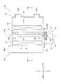
- FIG. 2 is a cross-sectional view taken along line II-II of the air conditioning unit shown in FIG. 1.
- FIG. 3 is a sectional view taken along line III-III of the air conditioning unit shown in FIG. 1.
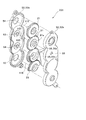
- FIG. 2 is an exploded perspective view showing the door device shown in FIG. 1.
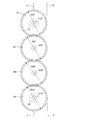
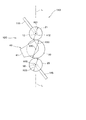
- FIG. 6 is a plan view showing a first gear, a second gear, and an intermediate gear of the door device shown in FIG. 5.
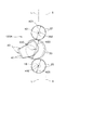
- FIG. 7 is a diagram for explaining a difference in maximum value of a difference between a rotation phase of a gear rotationally driven by the rotation driving unit and a rotation phase of a first gear or a second gear due to a difference in a gear rotationally driven by the rotation driving unit. ..
- FIG. 7 is a diagram for explaining a difference in maximum value of a difference between a rotation phase of a gear rotationally driven by the rotation driving unit and a rotation phase of a first gear or a second gear due to a difference in a gear rotationally driven by the rotation driving unit.
- FIG. 8 is a plan view showing a drive mechanism according to a modified example 1.
- 14 is a plan view showing a drive mechanism according to Modification 2.
- FIG. 14 is a plan view showing a drive mechanism according to Modification 3.
- FIG. 13 is an exploded perspective view showing a first gear, a second gear, and an intermediate gear according to Modification Example 4.
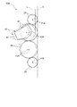
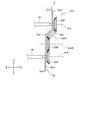
- FIG. It is a figure corresponding to Drawing 2, and is a sectional view showing an air harmony part by modification 5.
- FIG. 11 is a plan view showing a drive mechanism according to Modification 5.
- FIG. 14 is a plan view showing a drive mechanism according to Modification 6.
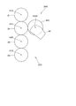
- FIG. 13 is a diagram showing a first gear, a second gear, and an intermediate gear according to Modification 7 as seen in the air flow direction in the air conditioning case. It is a top view of a bevel gear.
- FIG. 13 is a plan view showing a drive mechanism according to Modification 8.
- FIG. 11 is a plan view showing a drive mechanism according to Modification 9.
- FIG. 1 is a side view schematically showing a configuration of an air conditioning unit of an air conditioner according to an embodiment of the present invention.
- 2 is a cross-sectional view of the air conditioning unit shown in FIG. 1 taken along the vertical direction.
- FIG. 2 shows a cross section taken along the line II of FIG. 3 and 4 are cross-sectional views of the air conditioning unit shown in FIG. 1, taken along lines II-II and III-III, respectively.
- FIG. 5 is an exploded perspective view showing the door device shown in FIG. ..
- the air conditioning unit 1 a of the vehicle air conditioner 1 has an air conditioning case 2.
- the air conditioning case 2 forms an air passage 3 through which air flows. More specifically, as shown in FIGS. 3 and 4, the upstream end 2a of the air conditioning case 2 is formed with a connection port 300 for connection with a blower (not shown), and is blown out from the blower. The fresh air flows into the air passage 3 of the air conditioning case 2 through the connection port 300.
- a plurality of outlet passages 301, 302, 303 are formed at the downstream end 2b of the air conditioning case 2, and the air flowing into the air passage 3 flows out through the outlet passages 301, 302, 303. ing. ..
- the plurality of outlet passages of the air conditioning case 2 include a defrost outlet passage 301, a vent outlet passage 302, and a foot outlet passage 303.
- the defrost outlet passage 301 is provided on the top surface 2 c of the air conditioning case 2.
- the downstream end of the defrost outlet passage 301 is connected to a defrost outlet (not shown) that blows air toward the inner surface of the windshield inside the vehicle compartment.
- the vent outlet passage 302 is provided in an upper portion of the downstream end surface 2d of the air conditioning case 2.
- the downstream end of the vent outlet passage 302 is connected to a vent outlet (not shown) that blows air toward the upper half of the occupant seated in the driver's seat and the passenger seat (and in some cases, the rear seat).
- the foot outlet passage 303 is provided in the lower portion of the downstream end surface 2d of the air conditioning case 2.
- the downstream end of the foot outlet passage 303 is connected to a foot outlet (not shown) that blows air toward the feet of an occupant sitting in the driver's seat and the passenger seat (and in some cases, the rear seat). ..
- the cooling heat exchanger (evaporator) 4, the heating heat exchanger (heater core) 5, and the air passage 3 flow through the air passage 3 of the air conditioning case 2.
- Various doors air mix doors 11 and 15 and outlet passage doors 301D, 302D, and 303D) that change the flow of air are provided.
- a drive mechanism 20 for driving the air mix doors 11 and 15 is provided on the side surface 2g on the left side of the air conditioning case 2 when viewed from the driver's seat. In the illustrated example, the drive mechanism 20 and the air mix doors 11 and 15 form a door device 10. ..
- the cooling heat exchanger (evaporator) 4 is provided so that all the air flowing into the air conditioning case 2 passes through the cooling heat exchanger 4. Specifically, the cooling heat exchanger 4 is provided so as to occupy the entire cross-sectional area of the air passage 3.
- the heat exchanger 4 for cooling removes heat from the air passing therethrough, and when the humidity of the air is high, the moisture in the air is condensed to reduce the humidity of the air. ..
- the heating heat exchanger (heater core) 5 is arranged downstream of the cooling heat exchanger 4 in the air passage 3 formed by the air conditioning case 2.
- the heat exchanger 5 for heating heats the air passing therethrough. ..
- the heating heat exchanger 5 does not occupy the entire cross-sectional area of the air passage 3.
- an upper detour 3a is formed above the heating heat exchanger 5 and a lower detour 3b is formed below it.
- the air flowing in the air passage 3 does not pass through the heating heat exchanger 5 (bypasses the heating heat exchanger 5) and flows to the downstream side of the heating heat exchanger 5.
- the left side surface 2g of the air conditioning case 2 is provided with an insertion hole 2m for inserting the heating heat exchanger 5 into the air conditioning case 2. ..
- the air mix doors 11 and 15 are provided between the cooling heat exchanger 4 and the heating heat exchanger 5 in the air flow direction.
- the air mix doors 11 and 15 are plate-shaped members and are arranged substantially parallel to the upstream surface of the heating heat exchanger 5.
- the air mix doors 11 and 15 are provided in the upper part and the lower part of the air passage 3, respectively, so that the opening degree of the upper bypass 3a and the lower bypass 3b can be adjusted.
- the air mix door 11 arranged in the upper part of the air passage 3 is also referred to as "first air mix door 11”
- the air mix door 15 arranged in the lower part of the air passage 3 is referred to as "second air mix”. Also referred to as the door 15. ..
- FIGS. 2 corresponds to the vertical direction.
- 31 and 35 are not limited to be aligned in the vertical direction (vertical direction).
- the extending directions of the shafts 12 and 16 and shafts 301s, 302s, and 303s, which will be described later, coincide with the left-right direction in FIGS. 3 and 4.
- the first air mix door 11 can slide in the upper portion of the air passage 3 in the vertical direction. And the 1st air mix door 11 adjusts the ratio of the air which goes to upper part 5a of heat exchanger 5 for heating, and the air which goes to upper detour 3a according to the position.
- the second air mix door 15 can slide in the lower portion of the air passage 3 along the vertical direction. The 2nd air mix door 15 adjusts the ratio of the air which goes to lower part 5b of heat exchanger 5 for heating, and the air which goes to lower detour 3b according to the position. ..
- the first air mix door 11 and the second air mix door 15 are respectively connected to shafts 12 and 16 extending in the air passage 3 in the left-right direction. , 16 slides in the upper part and the lower part of the air passage 3 along the vertical direction. More specifically, as shown in FIG. 5, racks 11r and 15r are provided on one surface of each of the air mix doors 11 and 15 from the upper edge to the lower edge thereof. Gears 12p and 16p that mesh with the racks 11r and 15r are provided on the outer peripheral surfaces of the shafts 12 and 16, respectively.
- first shaft 12 the shaft 12 connected to the first air mix door 11
- second shaft 16 the shaft 16 connected to the second air mix door 15
- the shafts 12 and 16 are rotatably supported by the left and right side surfaces 2g and 2h of the air conditioning case 2 at both ends thereof.
- the left ends of the shafts 12 and 16 extend outside the air conditioning case 2 and are connected to the drive mechanism 20. ..
- the first air mix door 11 slides in the upper portion of the air passage 3 in the vertical direction, so that the air flowing toward the upper portion 5a of the heating heat exchanger 5 and the upper bypass 3a are separated. Adjust the ratio with the air going. That is, the opening area of the upper bypass 3a is changed by sliding the first air mix door 11 along the vertical direction, and the upper portion 5a of the heating heat exchanger 5 is viewed in the air flow direction. The area of the portion overlapping the first air mix door 11 is changed. As a result, the ratio of the air toward the upper bypass 3a and the air toward the upper portion 5a of the heating heat exchanger 5 in the upper portion of the air passage 3 is changed. Specifically, in FIG.
- the position where the opening area of the upper bypass 3a of the first air mix door 11 is minimized (the position shown by the solid line in FIG. 2) is called the “upper first position", and the opening area of the upper bypass 3a is the maximum.
- the position (the position indicated by the broken line in FIG. 2) to be set is called the “upper second position”. ..
- the second air mix door 15 slides in the lower portion of the air passage 3 in the up-down direction, so that the air flowing toward the lower portion 5b of the heating heat exchanger 5 and the lower portion of the air can be lowered.
- the ratio with the air that goes to the side bypass 3b is adjusted. That is, the opening area of the lower bypass 3b is changed by sliding the second air mix door 15 along the vertical direction, and the lower portion of the heating heat exchanger 5 is viewed in the air flow direction. The area of the portion of 5b overlapping the second air mix door 15 is changed. As a result, the ratio of the air directed to the lower bypass 3b in the lower part of the air passage 3 to the air directed to the lower part 5b of the heating heat exchanger 5 is changed.
- FIG. 2 when the second air mix door 15 is at the position shown by the solid line, the opening area of the lower bypass 3b is minimized, and the lower part of the heating heat exchanger 5 is arranged in the air flow direction.
- the area of the portion of the side portion 5b overlapping the second air mix door 15 is minimized.
- the proportion of air toward the lower bypass 3b is minimized, while the proportion of air toward the heating heat exchanger 5 is maximized.
- the opening area of the lower bypass 3b when the second air mix door 15 is at the position shown by the broken line, the opening area of the lower bypass 3b is maximized, and the lower portion 5b of the heating heat exchanger 5 in the air flow direction.
- the area of the portion overlapping with the second air mix door 15 is maximized.
- the proportion of air toward the lower bypass 3b is maximized, while the proportion of air toward the heating heat exchanger 5 is minimized. ..
- the position where the opening area of the lower bypass 3b of the second air mix door 15 is minimized (the position shown by the solid line in FIG. 2) is called the "lower first position", and the opening of the lower bypass 3b is called.
- the position where the area is maximized (the position shown by the broken line in FIG. 2) is called the "lower second position”. ..
- the door device 10 when the first air mix door 11 is at the upper first position (the position shown by the solid line in FIG. 2), the door device 10 has the second air mix door 15 at the lower first position.
- the first air mix door 11 is in the position (the position shown by the solid line in FIG. 2) and is in the upper second position (the position shown by the broken line in FIG. 2), the second air mix door 15 is the lower second position. It is configured to be in the position (the position shown by the broken line in FIG. 2).
- the positions of the first air mix door 11 and the second air mix door 15 are, for example, the operation mode and set temperature of the air conditioner 1 set by the occupant, the actual temperature inside the vehicle compartment, the amount of solar radiation received by the vehicle, and the outside air temperature of the vehicle. Is controlled on the basis of the target outlet temperature calculated using. As a result, air having a temperature set by the occupant according to the operation mode of the air conditioner 1, the set temperature, and the like is blown into the vehicle interior. ..
- the positions of the air mix doors 11 and 15 correspond to the rotation phases of the shafts 12 and 16, respectively. Therefore, the positions of the air mix doors 11 and 15 are controlled by controlling the rotation phases of the shafts 12 and 16. ..
- the blowout passages 301, 302, 303 are formed in the portion on the downstream side of the heating heat exchanger 5 of the air conditioning case 2 (see FIGS. 1 and 2).
- the defrost outlet passage 301 and the vent outlet passage 302 are provided in the upper portion of the air conditioning case 2. Air that has passed through the upper portion 5a of the heating heat exchanger 5 and/or the upper bypass 3a tends to easily enter the blowout passages 301 and 302.
- the foot outlet passage 303 is formed in the lower portion of the air conditioning case 2. Air that has passed through the lower portion 5b of the heating heat exchanger 5 and/or the lower bypass 3b tends to easily enter the blowout passages 303. ..
- the blow-out passage doors 301D, 302D, 303D are provided in the defrost blow-out passage 301, the vent blow-out passage 302, and the foot blow-out passage 303, respectively, and adjust the opening areas of the corresponding blow-out passages 301, 302, 303.
- the outlet passage doors 301D, 302D, 303D are referred to as "defrost door 301D” and "defrost door 301D", respectively.
- the vent door 302D" and the "foot door 303D" are also called. ..
- the outlet passage doors 301D, 302D, 303D are plate-shaped members extending from the shafts 301s, 302s, 303s extending in the left-right direction inside the air conditioning case 2.
- the outlet passage doors 301D, 302D, 303D open or close the corresponding outlet passages 301, 302, 303 by the shafts 301s, 302s, 303s being rotated by a drive mechanism (not shown).
- the opening degree of these doors 301D, 302D, 303D is controlled by a control unit including an in-vehicle microcomputer or the like, and the opening areas of the blowout passages 301, 302, 303 can be set to arbitrary opening areas. ..
- the operation modes of the air conditioner 1 shown in FIGS. 1 to 5 include, for example, a defrost mode, a differential foot mode, a foot mode, a vent mode, a bilevel mode, and the like.
- a defrost mode the defrost door 301D is opened, the vent door 302D and the foot door 303D are closed, and conditioned air is blown from the defrost outlet.
- the differential foot mode the defrost door 301D and the foot door 303D are opened, and the vent door 302D is closed, so that conditioned air is blown from the defrost outlet and the foot outlet.
- the defrost door 301D and the vent door 302D are closed, the foot door 303D is opened, and conditioned air is blown out from the foot outlet.
- the vent mode the vent door 302D is opened, the defrost door 301D and the foot door 303D are closed, and conditioned air is blown out from the vent outlet.
- the bilevel mode the vent door 302D and the foot door 303D are opened, the defrost door 301D is closed, and conditioned air is blown from the vent outlet and the foot outlet. ..
- the drive mechanism 20 that rotationally drives the first shaft 12 and the second shaft 16 will be described with reference to FIGS. 1 to 8.
- the drive mechanism 20 of the present embodiment when viewed in the extending direction of the rotation axis lines X12, X16 of the shafts 12, 16, the dimension along the extending direction of the straight line L connecting the two rotation axis lines X12, X16 is suppressed.
- the device for it is made.
- the drive mechanism 20 is designed to control the air mix doors 11 and 15 with high reliability.
- the straight line L can be defined as a straight line defined by the intersection of the plane connecting the two rotation axis lines X12 and X16 and the side surface of the air conditioning case 2 on the side where the drive mechanism 20 is arranged. ..
- FIG. 6 is a diagram showing the first gear 21, the second gear 25, and the intermediate gears 31, 35 of the door device 10 shown in FIG. 5 as viewed in the direction in which the rotation axes X12, X16 of the shafts 12, 16 extend.
- 7 and 8 are views for explaining the difference in the rotational phase of the first gear 21 or the second gear 25 with respect to the operation amount of the rotary drive unit 40 due to the difference in the gears rotationally driven by the rotary drive unit 40. Is. ..
- the drive mechanism 20 is arranged outside the air conditioning case 2 so as to face the left side surface 2 g of the air conditioning case 2.
- the drive mechanism 20 includes a first gear 21 connected to the first shaft 12, a second gear 25 connected to the second shaft 16, a first gear 21 and a second gear 25. It has a first intermediate gear 31 and a second intermediate gear 35, which are arranged between the two, and a rotation drive unit 40.
- the first gear 21, the second gear 25, the first intermediate gear 31, and the second intermediate gear 35 are spur gears, and are arranged vertically on the same plane.
- the gear case 50 includes a first gear case half body 50 a arranged facing the air conditioning case 2 and a first gear case half body 50 a sandwiching the gears 21, 25, 31, 35.
- a second gear case half 50b arranged to face the body 50a.
- the first gear 21 is fixed to one end portion (left end portion) of the first shaft 12 and rotates around the rotation axis X12 of the first shaft 12.
- the second gear 25 is fixed to one end (left end) of the second shaft 16 and rotates around the rotation axis X16 of the second shaft 16. More specifically, as shown in FIG. 5, the left end portions of the first shaft 12 and the second shaft 16 pass through openings 51 and 52 formed in the first gear case half body 50a, respectively, It is connected to the first gear 21 and the second gear 25. ..
- the first intermediate gear 31 and the second intermediate gear 35 are rotatably arranged between the first gear 21 and the second gear 25. More specifically, as shown in FIG. 5, two shaft portions 53 and 54 project from the inner surface of the first gear case half body 50a, and the first intermediate gear 31 and the second intermediate gear 35 are , Are rotatably supported by the corresponding shaft portions 53 and 54. In the example shown in FIG. 5, the shaft portions 53 and 54 extend parallel to the rotation axis lines X12 and X16 of the first shaft 12 and the second shaft 16. Each of the intermediate gears 31 and 35 is rotatable about rotation axis lines X31 and X35 parallel to the rotation axis lines X12 and X16. ..
- adjacent gears mesh with each other.
- the first gear 21 and the first intermediate gear 31 mesh with each other.
- the first intermediate gear 31 and the second intermediate gear 35 mesh with each other.
- the second intermediate gear 35 and the second gear 25 mesh with each other. ..
- the rotation drive unit 40 rotationally drives any of the first gear 21, the second gear 25, the first intermediate gear 31, and the second intermediate gear 35.
- the rotation drive unit 40 includes an actuator 41.
- the actuator 41 is connected to the first intermediate gear 31. More specifically, the rotary shaft 31a of the first intermediate gear 31 passes through the opening 55 provided in the second gear case half body 50b and is connected to the actuator 41. As a result, when the rotational driving force of the actuator 41 is transmitted to the first intermediate gear 31, the first intermediate gear 31 rotates around the rotation axis line X31 clockwise or counterclockwise. ..
- the rotational driving force of the actuator 41 is transmitted to the first gear 21 and the second intermediate gear 35 via the first intermediate gear 31, and further transmitted to the second gear 25 via the second intermediate gear 35. ..
- the first gear 21 and the second intermediate gear 35 rotate in the rotation direction opposite to the rotation direction of the first intermediate gear 31, and the second gear 25 rotates in the rotation direction opposite to the rotation direction of the second intermediate gear 35. Rotate to. That is, the first gear 21 and the second gear 25 rotate in different rotation directions.
- the first air mix door 11 is moved from the upper first position shown by the solid line in FIG. 2 to the upper second position shown by the broken line, and at the same time, the second air mix door 15 is moved to the lower side shown by the solid line in FIG.
- the operation amount of the actuator 41 (that is, the rotation phase of the rotation shaft 31a of the first intermediate gear 31) is controlled by a control unit (not shown) including a vehicle-mounted microcomputer. ..
- the drive mechanism 20 is suppressed from protruding toward the top surface 2c side or the bottom surface 2e side of the air conditioning case 2 with respect to the shafts 12 and 16.
- the drive mechanism 20 when viewed in the direction in which the rotation axis lines X12, X16 of the shafts 12, 16 extend, the dimension of the drive mechanism 20 along the direction in which the straight line L connecting the two rotation axis lines X12, X16 extends is suppressed.
- the drive mechanism 20 is prevented from interfering with the piping, wiring, bulging portion, etc. provided near the top surface 2c or the bottom surface 2e of the air conditioning case 2. ..
- the member that interlocks the first gear 21 and the second gear 25 is composed of the gears 31 and 35, the risk that the interlocking member expands and contracts or breaks is reduced. As a result, the first gear 21 and the second gear 25, and thus the air mix doors 11 and 15 can be controlled with high reliability. ..
- the rotation drive unit 40 rotationally drives the intermediate gears 31 and 35, not the first gear 21 or the second gear 25, so that the controllability of the first gear 21 and the second gear 25 as a whole can be improved. it can. That is, between the adjacent gears among the first gear 21, the second gear 25, the first intermediate gear 31, and the second intermediate gear 35, play (play) is provided in the rotation direction of each gear.
- the rotation drive unit 40 rotationally drives the gears 31 and 35 located in the middle instead of the gears 21 and 25 located at the ends, so that the gears 21, 31, 35 and 25 are connected.
- the rotation drive unit 40 is connected to the first intermediate gear 31 as shown in FIG. 7, when the rotation drive unit 40 rotates the first intermediate gear 31 by the angle ⁇ °, the first gear 21 and The second intermediate gears 35 rotate by the angle ⁇ 1°, respectively. Further, the second gear 25 rotates by the angle ⁇ -2°. Therefore, the rotation phases of the first gear 21 and the second gear 25 are angles ⁇ -1° and ⁇ -2°, respectively. That is, the maximum difference between the rotation phase ⁇ ° of the gear 31 rotated by the rotation drive unit 40 and the rotation phase of the first gear 21 and the second gear 25 is 2°. Even when the rotation drive unit 40 is connected to the second intermediate gear 35, the difference between the rotation phase ⁇ ° of the gear 35 rotated by the rotation drive unit 40 and the rotation phase of the first gear 21 and the second gear 25. Is up to 2°. ..
- the rotation driving unit 40 when the rotation driving unit 40 rotates the first gear 21 by the angle ⁇ °, the first intermediate gear 31 rotates by the angle ⁇ . It rotates by -1°, and the second intermediate gear 35 rotates by an angle ⁇ -2°. Then, the second gear 25 rotates by the angle ⁇ 3°. That is, the maximum difference between the rotation phase ⁇ ° of the gear 21 rotated by the rotation drive unit 40 and the rotation phase of the first gear 21 and the second gear 25 is 3°. Even when the rotation driving unit 40 is connected to the second gear 25, the difference between the rotation phase ⁇ ° of the gear 25 rotated by the rotation driving unit 40 and the rotation phase of the first gear 21 and the second gear 25 is , The maximum is 3°. ..
- the rotary drive unit 40 when the rotary drive unit 40 rotationally drives the intermediate gears 31 and 35, the rotary drive unit 40 drives the first gear 21 or the second gear 25 as shown in FIG.
- the rotational phase of the gear rotationally driven by the rotational driving unit 40 and the first gear 21 and the second gear 25 due to the play between the gears 21, 25, 31 and 35. It is possible to suppress the maximum value of the difference from the rotation phase of.
- the rotational phases of the first gear 21 and the second gear 25, and thus the positions of the first air mix door 11 and the second air mix door 15 can be controlled with high accuracy. ..
- the drive mechanism 20 is devised to reduce the size of the air conditioner 1. Specifically, as shown in FIG. 10 described later, the first gear 21 and the second gear 25 are in contact with each other from one side when viewed in a direction in which the rotation axis lines X12, X16 of the first shaft 12 and the second shaft 16 extend.
- the intermediate gears 31 and 35 are arranged on one side of the virtual surface S (specifically, on the upstream side in the air flow direction).
- the insertion hole 2m for inserting the heating heat exchanger 5 into the air conditioning case 2 can be provided close to the first gear 21 and the second gear 25.
- the heat exchanger 5 for heating can be arranged close to the air mix doors 11 and 15, and the air conditioner 1 can be downsized. Further, by arranging the intermediate gears 31 and 35 in this way, a wide space can be secured on the side surface 2g of the air conditioning case 2 for disposing the drive mechanism that drives the blowout passage doors 301D, 302D, and 303D. You can ..
- the drive mechanism 20 is devised to further reduce the size of the drive mechanism 20.
- the first gear 21, the second gear 25, and the intermediate gears 31, 35 of the first gear 21, the second gear 25, and the intermediate gears 31, 35 are viewed in a direction in which the rotation axes X12, X16 of the first shaft 12 and the second shaft 16 extend.
- the rotation axis lines X12, X16, X31, X35 are located on the same straight line L.
- the reference circle diameters of the intermediate gears 31 and 35 become the minimum reference circle diameters according to the distances of the rotation axis lines X12 and X16 and the reference circle diameters of the first gear 21 and the second gear 25.
- the drive mechanism 20 is devised to improve the production efficiency of the air conditioner 1. That is, as described above, the intermediate gears 31 and 35 are rotatably arranged around the rotation axis lines X31 and X35 parallel to the rotation axis lines X12 and X16 of the first shaft 12 and the second shaft 16. Accordingly, when the drive mechanism 20 is assembled to the air conditioning case 2, the mounting direction of the intermediate gears 31 and 35 to the air conditioning case 2 and the mounting of the first gear 21 and the second gear 25 to the first shaft 12 and the second shaft 16 are performed. The connection direction can be matched. Thereby, the drive mechanism 20 can be efficiently assembled to the air conditioning case 2. In particular, in the illustrated example, the gears 21, 25, 31, 35 of the drive mechanism 20 are housed in the gear case 50 before being assembled in the air conditioning case 2. As a result, the gears 21, 25, 31 and 35 can be assembled together in the air conditioning case 2. ..
- the drive mechanism 20 described above can also be used as a drive door mechanism that drives the shafts 301s, 302s, 303s of the blowout passage doors 301D, 302D, 303D. ..
- the drive mechanism 20 may include three or more intermediate gears, and may include a single intermediate gear like the drive mechanisms 120 and 120A according to modified examples shown in FIGS. 14 and 15 described later. You may stay. ..
- door device 10 is an air conditioner 1 for a vehicle that has an air conditioning case 2 that forms an air passage 3 through which air flows.
- the door device 10 includes a first door (first air mix door) 11, a first shaft 12 that is connected to the first door 11 and moves the first door 11 in accordance with rotation in the circumferential direction, and a second door. (Second air mix door) 15, a second shaft 16 which is connected to the second door 15 and moves the second door 15 in accordance with the rotation in the circumferential direction, and the first shaft 12 and the second shaft 16 are rotated.
- a drive mechanism 20 for driving.
- the drive mechanism 20 is connected to the first shaft 12 and rotates around the rotation axis X12 of the first shaft 12 and the second gear 16, and is connected to the rotation shaft X16 of the second shaft 16.
- the second gear 25 that rotates, and one or more intermediate gears 31 and 35 that are rotatably arranged between the first gear 21 and the second gear 25, the first gear 21, the second gear 25, and the intermediate gear.
- the rotation drive unit 40 that rotationally drives one of the gears 31 and 35, and the adjacent gears of the first gear 21, the second gear 25, and the intermediate gears 31 and 35 mesh with each other.
- the two rotation axis lines X12 and X16 are The size of the drive mechanism 20 along the extending direction of the connecting straight line L is suppressed. Further, the drive mechanism 20 can control the doors 11 and 15 with high reliability. ..
- the imaginary surface S with which the first gear 21 and the second gear 25 contact from one side The intermediate gears 31 and 35 are arranged on one side.
- the insertion hole 2m for inserting the heating heat exchanger 5 into the air conditioning case 2 can be provided close to the first gear 21 and the second gear 25.
- the heating heat exchanger 5 can be arranged close to the doors 11 and 15, and the air conditioner 1 can be downsized. ..
- the rotation axes of the first gear 21, the second gear 25, and the intermediate gears 31, 35 are seen when the rotation axes X12, X16 of the first shaft 12 and the second shaft 16 extend.
- X12, X16, X31, and X35 are located on the same straight line L.
- the reference circle diameters of the intermediate gears 31 and 35 become the minimum reference circle diameters according to the distances of the rotation axis lines X12 and X16 and the reference circle diameters of the first gear 21 and the second gear 25.
- the one or more intermediate gears 31 and 35 are rotatable about the rotation axis lines X31 and X35 parallel to the rotation axis lines X12 and X16 of the first shaft 12 and the second shaft 16. It is located in.
- the mounting direction of the intermediate gears 31, 35 to the air conditioning case 2 coincides with the connecting direction of the first gear 21 and the second gear 25 to the first shaft 12 and the second shaft 16, and the gears 21, 25, 25.
- the parts 31 and 35 can be efficiently assembled to the air conditioning case 2. And the production efficiency of the air conditioner 1 can be improved. ..
- the rotation driving unit 40 includes the actuator 41 that generates the rotation driving force, and the actuator 41 includes any one of the first gear 21, the second gear 25, and the intermediate gears 31 and 35. Drive to rotate.
- the actuator 41 rotationally drives the intermediate gears 31 and 35.
- FIG. 9 is a diagram showing a drive mechanism 20A according to the first modification. Note that the gear case 50 is omitted in FIG. 9. ..
- the outer diameters R21, R25 of the first gear 21 and the second gear 25 are the outer diameters R31, R31 of the intermediate gears 31, 35. The difference is that it is smaller than R35.
- the other structure is substantially the same as that of the drive mechanism 20 shown in FIGS.
- the same parts as those in the embodiment shown in FIGS. 1 to 8 are designated by the same reference numerals, and detailed description thereof will be omitted. ..
- the outer diameters R21 and R25 of the first gear 21 and the second gear 25 are smaller than the outer diameters R31 and R35 of the intermediate gears 31 and 35.
- the outer diameters R31 and R35 of the intermediate gears 31 and 35 are increased in comparison with the drive mechanism 20 shown in FIGS.
- the outer diameters R21 and R25 are reduced.
- the drive mechanism 20A can be more effectively suppressed from protruding toward the top surface 2c side or the bottom surface 2e side with respect to the shafts 12 and 16.
- the dimension of the drive mechanism 20A along the extending direction of the straight line L connecting the two rotation axis lines X12, X16 when viewed in the extending direction of the rotation axis lines X12, X16 of the shafts 12, 16 is more effectively suppressed. can do. ..
- the outer diameters R21 and R25 of the first gear 21 and the second gear 25 are smaller than the outer diameters R31 and R35 of the intermediate gears 31 and 35.
- the dimension of the drive mechanism 20A along the extending direction of the straight line L connecting the two rotation axis lines X12, X16 when viewed in the extending direction of the rotation axis lines X12, X16 of the shafts 12, 16 is more effectively suppressed. can do. ..
- the rotation axes X12 of the first gear 21, the second gear 25, and the intermediate gears 31, 35 are seen when the rotation axes X12, X16 of the first shaft 12 and the second shaft 16 extend.
- X16, X31, X35 are located on the same straight line L.
- the reference circle diameters of the intermediate gears 31 and 35 become the minimum reference circle diameters according to the distances of the rotation axis lines X12 and X16 and the reference circle diameters of the first gear 21 and the second gear 25.
- FIG. 10 is a diagram showing a drive mechanism 20B according to the second modification. Note that the gear case 50 is omitted in FIG. 10. ..
- the rotation axes X31, X35 of the intermediate gears 31, 35 are on the straight line L connecting the rotation axis X12 of the first shaft 12 and the rotation axis X12 of the second shaft 16. It is in a position outside of.
- the intermediate gears 31 and 35 are arranged such that the rotation axis lines X31 and X35 deviate from the straight line L, the intermediate gears 31 and 35 can easily be subjected to excessive force from the first gear 21 and the second gear 25. It can be moved (see the alternate long and short dash line in FIG. 10).
- the intermediate gears 31, 35 move and the gears 21, 31, 35. , 25 can be a distance suitable for rotation of the gears 21, 31, 35, 25. That is, the excessive force from the first gear 21 and the second gear 25 causes the distance between the gears 21, 31, 35, and 25 to be too small, and the rotation of the gears 21, 31, 35, and 25 is impeded (the gears). (21, 31, 35, 25 are in a locked state). ..
- the rotation axes X31 and X35 of the intermediate gears 31 and 35 correspond to the first shaft 12 respectively.
- the intermediate gears 31, 35 move and the gears 21, 31,
- the distance between 35 and 25 can be a distance suitable for rotation of the gears 21, 31, 35 and 25.
- the first gear 21 and the second gear 25 are on one side when viewed in the direction in which the rotation axis lines X12, X16 of the first shaft 12 and the second shaft 16 extend.
- the intermediate gears 31 and 35 are arranged on one side of the virtual surface S that is in contact with (specifically, on the upstream side in the air flow direction).
- the insertion hole 2m for inserting the heating heat exchanger 5 into the air conditioning case 2 can be provided close to the first gear 21 and the second gear 25.
- the heat exchanger 5 for heating can be arranged close to the air mix doors 11 and 15, and the air conditioner 1 can be downsized.
- FIG. 11 is a diagram showing a drive mechanism 20C according to Modification 3. Note that the gear case 50 is omitted in FIG. 11. ..
- the rotation axes X31 and X35 of the intermediate gears 31 and 35 are the rotation axis X12 of the first shaft 12 and the rotation axis X2 of the second shaft 16. They are different in that they are located on one side and the other side of a straight line L connecting X12.
- the other structure is substantially the same as that of the drive mechanism 20B shown in FIG.
- the same parts as those in Modification 2 shown in FIG. 10 are designated by the same reference numerals, and detailed description thereof will be omitted. ..
- the rotation axes X31 and X35 of the intermediate gears 31 and 35 are the first and the second rotation axes X12 and X16 of the first shaft 12 and the second shaft 16 when viewed in the extending direction. It is located at a position deviating from the straight line L connecting the rotation axis X12 of the first shaft 12 and the rotation axis X12 of the second shaft 16.
- the rotation axis lines X31, X35 of the intermediate gears 31, 35 are located on one side and the other side of the straight line L, respectively.
- the intermediate gears 31 and 35 can easily move when receiving excessive force from the first gear 21 and the second gear 25 (see FIG. 11). (See dashed line). Therefore, even if the distance between the first shaft 12 and the second shaft 16 becomes shorter than the desired distance due to, for example, a dimensional error of the air conditioning case 2, the intermediate gears 31, 35 move and the gears 21, 31, 35. , 25 can be a distance suitable for rotation of the gears 21, 31, 35, 25. That is, the excessive force from the first gear 21 and the second gear 25 causes the distance between the gears 21, 31, 35, and 25 to be too small, and the rotation of the gears 21, 31, 35, and 25 is impeded (the gears). (21, 31, 35, 25 are in a locked state). ..
- FIG. 11 is an exploded perspective view showing a drive mechanism 20D according to Modification 4. ..
- Modified Example 4 shown in FIG. 12 is different from the drive mechanism 20 shown in FIGS. 1 to 8 in that the second intermediate gear 35 has a plurality of gear portions 35a and 35b. Further, the second gear 25 is different in that it is a sector gear. Other configurations are substantially the same as the drive mechanism 20 shown in FIGS. 1 to 8.
- Modification 4 shown in FIG. 12 the same parts as those of the embodiment shown in FIGS. 1 to 8 are designated by the same reference numerals, and detailed description thereof will be omitted.
- the second intermediate gear 35 shown in FIG. 12 has a plurality of gear portions 35a and 35b arranged in a direction in which the rotation axis X35 of the second intermediate gear 35 extends.
- the plurality of gear portions 35a and 35b are fixed to each other and rotate together around the rotation axis X35.
- the second intermediate gear 35 includes a large diameter gear portion 35a and a small diameter gear portion 35b.
- the reference circle diameter of the small diameter gear portion 35b is smaller than the reference circle diameter of the large diameter gear portion 35a.
- the large-diameter gear portion 35a meshes with the first intermediate gear 31.
- the small-diameter gear portion 35b meshes with the second gear 25.
- the reference circle diameter of the second gear 25 has a size corresponding to the reference circle diameter of the small diameter gear portion 35b. Therefore, when the first intermediate gear 31 is rotated by the actuator 41, the second intermediate gear 35 transmits the rotation of the first intermediate gear 31 to the second gear 25 via the large diameter gear portion 35a and the small diameter gear portion 35b. To do. At this time, the second intermediate gear 35 rotates the second gear 25 at a rotation speed corresponding to the reference circle diameter of the small diameter gear portion 35b and the second gear 25. That is, in the drive mechanism 20D shown in FIG. 12, the second gear 25 can be rotated at a desired speed by adjusting the reference circle diameters of the small diameter gear portion 35b and the second gear 25. Therefore, the second air mix door 15 can be moved at a desired speed. For example, the second air mix door 15 can be moved more slowly than the first air mix door 11. ..
- the second gear 25 may be a sector gear, and the straight line L connecting the two rotation axis lines X12 and X16 may pass through the fan regardless of the rotational position of the second gear 25.
- the dimensions of the second gear 25 along the direction in which the straight line L extends can be made to correspond to the portion of the fan shape having the smaller radius, and the drive mechanism The size of 20D can be suppressed more effectively. ..
- the first intermediate gear 31 may have a plurality of gear parts.
- the first gear 21 can be rotated at a desired speed by adjusting the gear portion that meshes with the first gear 21 and the reference circle diameter of the first gear 21. Therefore, the first air mix door 11 can be moved at a desired speed. For example, the first air mix door 11 can be moved more slowly than the second air mix door 15. ..
- the first gear 21 may be a fan gear, and the straight line L connecting the two rotation axis lines X12 and X16 may be arranged so as to pass through the fan regardless of the rotation position of the first gear 21.
- the size of the first gear 21 along the extending direction of the straight line L connecting the two rotation axis lines X12, X16 is determined by The size of the drive mechanism 20D can be more effectively suppressed by corresponding to the portion having a small radius. ..
- FIG. 13 is a cross-sectional view showing the configuration of the air conditioning unit 100a of the air conditioning device 100 according to Modification 5.
- FIG. 14 is a diagram showing a door device 110 used in the air conditioning unit 100a shown in FIG. ..
- the shafts 12 and 16 are arranged on the upstream side and the downstream side of the heating heat exchanger 5, respectively, as compared with the door device 10 shown in FIGS. 1 to 8. They differ in points. Further, the first air mix door 111 and the second air mix door 115 are different in that they rotate around the rotation axes X12, X16 of the corresponding shafts 12, 16. It is also different in that the drive mechanism 120 has a single intermediate gear 30. Other configurations are substantially the same as the door device 10 shown in FIGS. 1 to 8. In Modification 5 shown in FIGS. 13 and 14, the same parts as those of the embodiment shown in FIGS. 1 to 8 are designated by the same reference numerals, and detailed description thereof will be omitted. ..
- the heating heat exchanger 5 has its upper end located downstream of the first shaft 12 and its lower end located upstream of the second shaft 16 in the air flow direction. Are arranged as follows. ..
- the first air mix door 111 is a plate-shaped member extending from the first shaft 12, and rotates around the rotation axis X12 as the first shaft 12 rotates.
- the second air mix door 115 is a plate-shaped member extending from the second shaft 16, and rotates around the rotation axis X16 as the second shaft 16 rotates. ..
- the drive mechanism 120 is arranged outside the air conditioning case 2 so as to face the left side surface 2 g of the air conditioning case 2.
- the drive mechanism 120 includes a first gear 21 connected to the first shaft 12, a second gear 25 connected to the second shaft 16, a first gear 21 and a second gear 25.
- the first gear 21, the second gear 25, and the intermediate gear 30 are spur gears and are arranged side by side in the vertical direction on the same plane.
- the gears 21, 25, 30 are housed in a gear case (not shown). ..
- the first gear 21 is fixed to the left end portion of the first shaft 12 and rotates around the rotation axis X12 of the first shaft 12.
- the second gear 25 is fixed to the left end portion of the second shaft 16 and rotates around the rotation axis X16 of the second shaft 16 as in the example shown in FIG. ..
- the intermediate gear 30 is rotatably arranged between the first gear 21 and the second gear 25. More specifically, similarly to the example shown in FIG. 5, the shaft portion is rotatably supported by a shaft portion extending inside the gear case. In the example shown in FIG. 14, the intermediate gear 30 is rotatably supported around a rotation axis X30 parallel to the rotation axes X12 and X16 of the first shaft 12 and the second shaft 16. ..
- the actuator 41 of the rotary drive unit 40 is connected to the intermediate gear 30.
- the intermediate gear 30 rotates around the rotation axis X30 in the clockwise direction or the counterclockwise direction. ..
- the rotational driving force of the actuator 41 is transmitted to the first gear 21 and the second gear 25 via the intermediate gear 30.
- the first gear 21 and the second gear 25 rotate in the rotation direction opposite to the rotation direction of the intermediate gear 30. That is, the first gear 21 and the second gear 25 rotate in the same rotation direction.
- the drive mechanism 120 moves the first air mix door 111 from the upper first position shown by the solid line in FIG. 13 to the upper second position shown by the broken line, and at the same time moves the second air mix door 115 to the upper position shown in FIG.
- the lower first position shown by the solid line can be moved to the second lower position shown by the broken line.
- the first air mix door 111 can be moved from the upper second position to the upper first position, and at the same time, the second air mix door 115 can be moved from the lower second position to the lower first position. ..
- the ratio of the air directed to the upper portion 5a of the heat exchanger 5 for heating and the air directed to the upper bypass 3a is adjusted according to the position of the first air mix door 111.
- the ratio of the air heading for the lower portion 5b of the heating heat exchanger 5 to the air heading for the lower bypass 3b can be adjusted according to the position of the second air mix door 115.
- the size of the drive mechanism 120 along the extending direction of the straight line L connecting the two rotation axis lines X12, X16 can be suppressed.
- the air mix doors 111 and 115 can be controlled with high reliability. ..
- the rotation axes X12 of the first gear 21, the second gear 25, and the intermediate gear 30 are viewed in the directions in which the rotation axes X12, X16 of the first shaft 12 and the second shaft 16 extend. , X16, X30 are located on the same straight line L.
- the reference circle diameter of the intermediate gear 30 becomes the minimum reference circle diameter according to the distance between the rotation axes X12 and X16 and the reference circle diameters of the first gear 21 and the second gear 25.
- the outer diameters R21 and R25 of the first gear 21 and the second gear 25 are smaller than the outer diameter R30 of the intermediate gear 30.
- the rotation drive unit 40 rotationally drives the intermediate gear 30 instead of the first gear 21 or the second gear 25, so that the entire first gear 21 and the second gear 25 are controlled. It is possible to improve the sex. That is, the influence of play (play) provided between the gears 21, 30, and 25 on the controllability of the first gear 21 and the second gear 25 can be effectively suppressed, and the first air mix door 111. And the 2nd air mixing door 115 can be controlled with high precision. ..
- the intermediate gear 30 is rotatably arranged around a rotation axis X30 parallel to the rotation axes X12, X16 of the first shaft 12 and the second shaft 16.
- the mounting direction of the intermediate gear 30 to the air conditioning case 2 coincides with the connecting direction of the first gear 21 and the second gear 25 to the first shaft 12 and the second shaft 16, and the gears 21 and 25 are arranged.
- 30 can be efficiently assembled to the air conditioning case 2. Then, the production efficiency of the air conditioner 100 can be improved. ..
- FIG. 15 is a diagram showing a drive mechanism 120A according to Modification 6. ..
- the rotation axis line X30 of the intermediate gear 30 is It is located off the straight line L connecting the rotation axis X12 and the rotation axis X12 of the second shaft 16.
- the intermediate gear 30 can easily move (FIG. 15). See the dot-dash line).
- the distance between the gears 21, 30, and 25 can be set to an appropriate distance for the rotation of the gears 21, 30, and 25. Therefore, the excessive force from the first gear 21 and the second gear 25 causes the distance between the gears 21, 30, 25 to be too small, and the rotation of the gears 21, 30, 25 is hindered (the gears 21, 30, 25). 25 is locked).
- the drive mechanism 120A shown in FIG. 15 when viewed in the direction in which the rotation axis lines X12, X16 of the first shaft 12 and the second shaft 16 extend, the virtual surface S where the first gear 21 and the second gear 25 are in contact from one side
- the intermediate gear 30 is disposed on one side (specifically, on the upstream side in the air flow direction).
- a large space can be secured on the side surface 2g of the air conditioning case 2 for disposing the drive mechanism that drives the blowout passage doors 301D, 302D, 303D. ..
- FIG. 16 is a diagram showing the structure of the drive mechanism 220 according to Modification 7 as viewed from the upstream side to the downstream side in the air flow direction.
- the rotary drive unit 40 and the gear case 50 are not shown.
- 17 is a plan view showing a bevel gear used as the first gear 221, the second gear 225, and the second intermediate gear 235 of the drive mechanism 220 shown in FIG. ..
- one of the intermediate gears 231 and 235 has one of the intermediate gears 231 whose rotation axis line X12 of the first shaft 12 and the second shaft 16.
- X16 are arranged so as to be rotatable about a rotation axis X231 that is not parallel to X16.
- the other structure is substantially the same as that of the drive mechanism 20 shown in FIGS.
- Modification 7 shown in FIGS. 16 and 17 the same parts as those of the embodiment shown in FIGS. 1 to 8 are designated by the same reference numerals, and detailed description thereof will be omitted. ..
- the drive mechanism 220 shown in FIG. 16 includes a first gear 221 connected to the first shaft 12 and a second gear 225 connected to the second shaft 16 as in the drive mechanism 20 shown in FIGS. 1 to 8. , And a first intermediate gear 231 and a second intermediate gear 235 arranged between the first gear 221 and the second gear 225. ..
- the left side surface 2g of the air conditioning case 2 has a step portion, and the first gear 221 and the second gear 225 are not located on the same plane.
- the portion 2ga of the side surface 2g of the air conditioning case 2 facing the first gear 221 is located on the left side of the driver's seat as compared to the portion 2gb facing the second intermediate gear 235 and the second gear 225. doing.
- the portion 2gc of the side surface 2g facing the first intermediate gear 231 is inclined from the left side to the right side from the upper side to the lower side when viewed from the driver's seat, and forms a stepped portion connecting the portions 2ga and 2gb. ing.
- Spur gears and a bevel gear shown in FIG. 17 are used for the gears 221, 225, 231, 235 of the drive mechanism 220 so as to be along the side surface 2g.
- the first gear 221, the second gear 225, and the second intermediate gear 235 are bevel gears
- the first intermediate gear 231 is a spur gear.
- the second intermediate gear 235 is arranged in parallel with the portion 2gb and is rotatably supported around a rotation axis X235 parallel to the rotation axes X12, X16 of the shafts 12, 16.
- the first intermediate gear 231 is arranged in parallel with the inclined portion 2gc, and is rotatably supported around a rotation axis X231 that is not parallel to the rotation axes X12 and X16 of the shafts 12 and 16. ..
- the second intermediate gear 235 may be rotatably supported around a rotation axis X235 that is not parallel to the rotation axes X12 and X16 of the shafts 12 and 16. Further, the rotation axes X231 and X235 of the first intermediate gear 231 and the second intermediate gear 235 may both be non-parallel to the rotation axes X12 and X16 of the shafts 12 and 16. ..
- At least one of the one or the plurality of intermediate gears 231 and 235 has a rotation axis X231 that is non-parallel to the rotation axes X12 and X16 of the first shaft 12 and the second shaft 16. It is arranged so that it can rotate around it. As a result, even when the first gear 221 and the second gear 225 are not on the same plane, the rotational driving force of the rotary drive unit 40 can be transmitted to the first gear 21 and the second gear 25. ..
- FIG. 18 is a diagram showing a drive mechanism 320 according to the modified example 8. ..
- the modified example 8 shown in FIG. 18 is different from the drive mechanism 20 shown in FIGS. 1 to 8 in that the rotary drive unit 340 includes a drive gear 342 which is rotationally driven by the actuator 41.
- the other structure is substantially the same as that of the drive mechanism 20 shown in FIGS.
- Modification 8 shown in FIG. 18 the same parts as those in the embodiment shown in FIGS. 1 to 8 are designated by the same reference numerals, and detailed description thereof will be omitted. ..
- the rotary drive unit 340 illustrated in FIG. 18 includes an actuator 41 that generates a rotary drive force, and a drive gear 342 that is rotationally driven by the actuator 41.
- the drive gear 342 meshes with the first intermediate gear 31.
- the rotation driving unit 340 can also rotate the gears 21, 31, 35 and 25 to move the air mix doors 11 and 15.
- the gear with which the drive gear 342 meshes is not limited to the first intermediate gear 31, and may be the first gear 21, the second intermediate gear 35, or the second gear 25. That is, the drive gear 342 may be in mesh with any of the first gear 21, the second gear 25, and the intermediate gears 31, 35. ..
- the drive gear 342 meshes with one of the intermediate gears 31 and 35 instead of the first gear 21 or the second gear 25.
- the controllability of the first gear 21 and the second gear 25 as a whole can be improved. That is, it is possible to effectively suppress the influence of play (play) provided between the gears 21, 31, 35, and 25 on the controllability of the first gear 21 and the second gear 25 as a whole.
- the mix door 11 and the second air mix door 15 can be controlled with high accuracy. ..
- the drive gear 342 is arranged rotatably around a rotation axis X342 parallel to the rotation axes X12 and X16 of the first shaft 12 and the second shaft 16.
- the drive gear 342 may be rotatably arranged around the rotation axis X342 that is not parallel to the rotation axes X12 and X16 of the first shaft 12 and the second shaft 16. ..
- FIG. 19 is a diagram showing a drive mechanism 320A according to Modification 9. ..
- the rotary drive unit 340A further includes a power transmission gear 343 between the drive gear 342 and the gears 21, 31, 35, 25. The difference is in the inclusion.
- the other structure is substantially the same as that of the drive mechanism 320 shown in FIG.
- the same parts as those in Modification 8 shown in FIG. 18 are designated by the same reference numerals, and detailed description thereof will be omitted. ..
- the rotary drive unit 340A shown in FIG. 19 is rotatably arranged between the actuator 41 that generates a rotary drive force, the drive gear 342 that is rotationally driven by the actuator 41, and the drive gear 342 and the first intermediate gear 31. And a power transmission gear 343.
- the drive gear 342 and the power transmission gear 343 are in mesh with each other, and the power transmission gear 343 and the first intermediate gear 31 are in mesh with each other.
- the rotary drive unit 340A can also rotate the gears 21, 31, 35, 25 to move the air mix doors 11, 15.
- the rotational driving force of the actuator 41 is configured to mesh with the first intermediate gear 31 via the drive gear 342 and the power transmission gear 343, so that the actuator 41 is a straight line connecting the two rotation axis lines X12 and X16. Even when it is difficult to dispose in the vicinity of L, the power can be transmitted to the two shafts 12 and 16. ..
- the gear with which the power transmission gear 343 meshes is not limited to the first intermediate gear 31, and may be the first gear 21, the second intermediate gear 35, or the second gear 25. That is, the drive gear 342 may be in mesh with any of the first gear 21, the second gear 25, and the intermediate gears 31, 35 via the power transmission gear 343. ..
- the power transmission gear 343 is not in mesh with the first gear 21 or the second gear 25, but with one of the intermediate gears 31 and 35.
- the controllability of the first gear 21 and the second gear 25 as a whole can be improved. That is, it is possible to effectively suppress the influence of play (play) provided between the gears 21, 31, 35, and 25 on the controllability of the first gear 21 and the second gear 25 as a whole.
- the mix door 11 and the second air mix door 15 can be controlled with high accuracy. ..
- the rotation drive unit 340A may include a plurality of power transmission gears 343 between the drive gear 342 and any of the gears 21, 31, 35, and 25.
- the adjacent gears of the drive gear 342 and the power transmission gear 343 should be in mesh with each other, and the adjacent gears of the gears 21, 31, 35, 25 and the power transmission gear 343 should be in mesh with each other. ..
- the drive gear 342 and the power transmission gear 343 are rotatably arranged around rotation axis lines X342 and X343 parallel to the rotation axis lines X12 and X16 of the first shaft 12 and the second shaft 16.
- rotation axis lines X342 and X343 parallel to the rotation axis lines X12 and X16 of the first shaft 12 and the second shaft 16.
- the first gear 21,221, the second gear 25,225, and the intermediate gears 30,31,35,231,235 have been described as being housed in the gear case 50, but the present invention is not limited to this.
- the door devices 10 and 100 may not include the gear case 50.
- the gear case 50 accommodates the drive gear 342 and the power transmission gear 343 in addition to the first gears 21 and 221, the second gears 25 and 225, the intermediate gears 30, 31, 35, 231, and 235. It may be one. The presence or absence of the gear case 50 and the gear accommodated in the gear case are appropriately selected.
- the door device according to the present invention can be industrially manufactured and can be a target of commercial transactions, and thus has an economical value and can be industrially used.
- Air conditioning case 3 Air passage 5 Heating heat exchanger 10,110 Door device 11,111 1st air mix door 12 1st shaft 15,115 2nd air mix door 16 2nd shaft 20 , 20A, 20B, 20C, 20D, 120, 120A, 220, 320, 320A drive mechanism 21,221 first gear 25,225 second gear 30,31,35,231,235 intermediate gear 40,340,340A rotational drive Part 41 actuator 342 drive gear 343 power transmission gear L straight line S virtual surface
Landscapes
- Physics & Mathematics (AREA)
- Thermal Sciences (AREA)
- Engineering & Computer Science (AREA)
- Mechanical Engineering (AREA)
- Air-Conditioning For Vehicles (AREA)
Abstract
【課題】ドアを信頼性高く制御可能な小型化された駆動機構を備えたドア装置を提供する。【解決手段】第1ドア(11)を移動させる第1シャフト(12)と、第2ドア(15)を移動させる第2シャフト(16)とを回転駆動する駆動機構(20)は、第1シャフト(12)に連結された第1ギア(21)と、第2シャフト(16)に連結された第2ギア(25)と、第1ギア(21)および第2ギア(25)の間に回転可能に配置された一つまたは複数の中間ギア(30)と、第1ギア(21)、第2ギア(25)および中間ギア(30)のいずれかを回転駆動する回転駆動部(40)と、を有する。
Description
本発明は、ドア装置に関する。
従来、内部に空気通路を形成する空調ケースと、空調ケースの内部に配置されて空気通路を通流する空気の流れを変更するドアと、を備えた車両用の空調装置が知られている。ドアは、例えば、空気通路内に配置された加熱用熱交換器を通過して加熱される空気と加熱用熱交換器を迂回する空気との比率を調整するエアミックスドアや、空調ケースに設けられた吹出通路を閉鎖または開放する吹出通路ドア等である。
特許文献1には、このようなドアを有するドア装置が示されている。特許文献1において、ドア装置は、上下に並んで配置された二枚のドアと、各々が対応するドアに連結された二本のシャフトと、当該二本のシャフトを回転駆動する駆動機構と、を含む。駆動機構は、空調ケースの外側において各々が対応するシャフトの端部に連結された二つのギアと、二つのギアと噛み合うラックと、を有している。そして、一方のギアの回転に伴ってラックが上下に移動することで、他方のギアが回転する。これにより、各ギアに連結された二本のシャフトが共に回転し、各シャフトに連結された二枚のドアが共に移動する。
ところで、このような駆動機構は、空調ケースの側面に配置される。空調ケースの側面には、駆動機構以外にも、空気通路に配置される空気冷却用熱交換器や空気加熱用熱交換器を保持しつつ熱交換器の周囲を空気が漏れないようにシールするために、膨出部が形成されることがある。また、空調ケースの側面のうち天面近傍あるいは底面近傍には、各種配管や配線が設けられることが多い。特許文献1に記載の駆動機構は、上下方向に移動するラックがこれらの配管や配線、膨出部と干渉する虞がある。
駆動機構が上記配管や配線、膨出部と干渉することを防止するため、上記シャフトよりも天面側あるいは底面側への駆動機構の突出量は、小さいことが好ましい。より一般的には、二つのシャフトの回転軸線の延びる方向に見て、当該二つの回転軸線を結ぶ直線の延びる方向に沿った駆動機構の寸法は、小さいことが好ましい。
この点に関し、特許文献2には、一方のシャフトを回転させるギアの回転駆動力を、ベルト部材を介して他方のシャフトに伝達する駆動機構が開示されている。このような駆動機構によれば、駆動機構の上記寸法を抑制することができる。しかしながら、ベルト部材が伸縮したり破断したりして、他方のシャフトの回転を(したがって当該シャフトに連結されたドアの移動を)、所望のように制御することができなくなる虞がある。
以上より、二つのドアの各々に連結された二つのシャフトの回転軸線の延びる方向に見て、当該二つの回転軸線を結ぶ直線の延びる方向に沿った寸法が抑制された駆動機構であって、ドアを信頼性高く制御可能な駆動機構を備えたドア装置の実現が求められている。
本発明は、二つのドアの各々に連結された二つのシャフトの回転軸線の延びる方向に見て、当該二つの回転軸線を結ぶ直線の延びる方向に沿った寸法が抑制された駆動機構であって、ドアを信頼性高く制御可能な駆動機構を備えたドア装置を提供することを目的としている。
本発明の好適な一実施の形態によれば、 内部に空気が流れる空気通路を形成する空調ケースを有する車両用の空調装置において、前記空気通路を通流する空気の流れを変更するドア装置であって、 第1ドアと、 前記第1ドアに連結されて、周方向の回転に伴って前記第1ドアを移動させる第1シャフトと、 第2ドアと、 前記第2ドアに連結されて、周方向の回転に伴って前記第2ドアを移動させる第2シャフトと、 前記第1シャフトおよび前記第2シャフトを回転駆動する駆動機構と、を備え、 前記駆動機構は、 前記第1シャフトに連結され、前記第1シャフトの回転軸線の周りを回転する第1ギアと、 前記第2シャフトに連結され、前記第2シャフトの回転軸線の周りを回転する第2ギアと、 前記第1ギアおよび前記第2ギアの間に回転可能に配置された一つまたは複数の中間ギアと、 前記第1ギア、前記第2ギアおよび前記中間ギアのいずれかを回転駆動する回転駆動部と、を有し、 前記第1ギア、前記第2ギアおよび前記中間ギアの隣り合うギアは、互いに噛み合っている、ドア装置が提供される。
上記本発明の実施形態によれば、二つのドアの各々に連結された二つのシャフトの回転軸線の延びる方向に見て、当該二つの回転軸線を結ぶ直線の延びる方向に沿った寸法が抑制された駆動機構であって、ドアを信頼性高く制御可能な駆動機構を備えたドア装置を提供することができる。
以下に、添付図面を参照して、本発明の一実施の形態について説明する。
図1は、本発明の一実施の形態による空調装置の空気調和部の構成を模式的に示す側面図である。また、図2は、図1に示す空気調和部の上下方向に沿った断面図である。具体的には、図2は、図3のI-I線に沿った断面を示している。また、図3および図4は、それぞれ、図1に示す空気調和部のII-II線およびIII-III線に沿った断面図である。なお、図3および図4では、後述する吹出通路ドアの図示が省略されている。また、図5は、図1に示すドア装置を示す分解斜視図である。
図1乃至図4に示すように、車両用の空調装置1の空気調和部1aは、空調ケース2を有している。空調ケース2は、内部に空気が流れる空気通路3を形成している。より具体的には、図3および図4に示すように、空調ケース2の上流側端部2aには、送風機(図示せず)と接続する接続口300が形成されており、送風機から吹き出された空気が接続口300を通じて空調ケース2の空気通路3に流れ込むようになっている。また、空調ケース2の下流側端部2bには、複数の吹出通路301,302,303が形成されており、空気通路3に流れ込んだ空気が吹出通路301,302,303から流出するようになっている。
空調ケース2の複数の吹出通路は、デフロスト吹出通路301と、ベント吹出通路302と、フット吹出通路303とを含む。図1および図2に示すように、デフロスト吹出通路301は、空調ケース2の天面2cに設けられている。デフロスト吹出通路301の下流端は、車室内のフロントガラスの内面に向けて空気を吹き出す図示しないデフロスト吹出口に接続されている。また、ベント吹出通路302は、空調ケース2の下流側端面2dの上側部分に設けられている。ベント吹出通路302の下流端は、運転席及び助手席(場合によっては後席も)に座っている乗員の上半身に向けて空気を吹き出す図示しないベント吹出口に接続されている。また、フット吹出通路303は、空調ケース2の下流側端面2dの下側部分に設けられている。フット吹出通路303の下流端は、運転席及び助手席(場合によっては後席も)に座っている乗員の足元に向けて空気を吹き出す図示しないフット吹出口に接続されている。
図1乃至図4に示すように、空調ケース2の空気通路3内には、冷却用熱交換器(エバポレータ)4、加熱用熱交換器(ヒータコア)5、及び、空気通路3を通流する空気の流れを変更する各種ドア(エアミックスドア11,15及び吹出通路ドア301D,302D,303D)が設けられている。また、運転席から見て空調ケース2の左側の側面2gには、エアミックスドア11,15を駆動する駆動機構20が設けられている。図示された例では、駆動機構20とエアミックスドア11,15とにより、ドア装置10が構成されている。
冷却用熱交換器(エバポレータ)4は、空調ケース2内に流入した空気の全てが冷却用熱交換器4を通過するように設けられている。具体的には、冷却用熱交換器4は、空気通路3の全断面積を占有するように設けられている。冷却用熱交換器4は、そこを通過する空気から熱を奪い、かつ、空気の湿度が高い場合には空気中の水分を凝縮させることにより空気の湿度を下げる。
加熱用熱交換器(ヒータコア)5は、空調ケース2が形成する空気通路3内において、冷却用熱交換器4の下流側に配置されている。加熱用熱交換器5は、そこを通過する空気を加熱する。
加熱用熱交換器5は、空気通路3の全断面積を占有してはいない。空調ケース2内において、加熱用熱交換器5の上方には上側迂回路3aが、下方には下側迂回路3bが形成されている。これらの迂回路3a,3bは、空気通路3内を流れる空気が加熱用熱交換器5を通過しないで(加熱用熱交換器5を迂回して)加熱用熱交換器5の下流側に流れることを可能にする。なお、図1に示すように、空調ケース2の左側の側面2gには、加熱用熱交換器5を空調ケース2内に挿入するための、挿入孔2mが設けられている。
エアミックスドア11,15は、空気の流れ方向における冷却用熱交換器4と加熱用熱交換器5との間に設けられている。図示の例では、エアミックスドア11,15は、板状の部材であり、加熱用熱交換器5の上流側の面に概ね平行に配置されている。エアミックスドア11,15は、それぞれ、空気通路3の上側部分及び下側部分に設けられ、上側迂回路3aおよび下側迂回路3bの開口度を調整することができるようになっている。以下では、空気通路3の上側部分に配置されたエアミックスドア11を「第1エアミックスドア11」とも呼び、空気通路3の下側部分に配置されたエアミックスドア15を「第2エアミックスドア15」とも呼ぶ。
なお、本明細書において、説明の便宜上、エアミックスドア11,15の並ぶ方向や後述するシャフト12,16の並ぶ方向、並びに、ギア21,25,31,35の並ぶ方向が、図1および図2の上下方向に一致している。しかしながら、このことによって、空調装置1が実際に車両に組み込まれた場合のエアミックスドア11,15の並ぶ方向やシャフト12,16の並ぶ方向、ギア21,25
,31,35の並ぶ方向が上下方向(鉛直方向)に一致するものと限定されるわけではない。また、シャフト12,16および後述するシャフト301s,302s,303sの延びる方向が、図3および図4の左右方向に一致している。しかしながら、このことによって、空調装置1が実際に車両に組み込まれた場合のシャフト12,16,301s,302s,303sの延びる方向が、運転席から見た左右方向に一致するものと限定されるわけではない。
,31,35の並ぶ方向が上下方向(鉛直方向)に一致するものと限定されるわけではない。また、シャフト12,16および後述するシャフト301s,302s,303sの延びる方向が、図3および図4の左右方向に一致している。しかしながら、このことによって、空調装置1が実際に車両に組み込まれた場合のシャフト12,16,301s,302s,303sの延びる方向が、運転席から見た左右方向に一致するものと限定されるわけではない。
第1エアミックスドア11は、空気通路3の上側部分内を上下方向に沿ってスライドすることができるようになっている。そして、第1エアミックスドア11は、その位置に応じて、加熱用熱交換器5の上側部分5aに向かう空気と、上側迂回路3aに向かう空気との比率を調整する。また、第2エアミックスドア15は、空気通路3の下側部分内を上下方向に沿ってスライドすることができるようになっている。第2エアミックスドア15は、その位置に応じて、加熱用熱交換器5の下側部分5bに向かう空気と、下側迂回路3bに向かう空気との比率を調整する。
図3および図4に示すように、第1エアミックスドア11および第2エアミックスドア15は、それぞれ、空気通路3内を左右方向に沿って延びるシャフト12,16に連結されており、シャフト12,16の回転に伴って、空気通路3の上側部分内および下側部分内を上下方向に沿ってスライドする。より具体的には、図5に示すように、各エアミックスドア11,15の一方の面には、その上端縁から下端縁に亘って、それぞれラック11r,15rが設けられている。また、各シャフト12,16の外周面には、このラック11r,15rと噛み合うギア12p,16pが設けられている。そして、シャフト12,16を周方向に回転させると、シャフト12,16の回転運動がギア12p,16pとラック11r,15rとによって上下方向の運動に変換され、エアミックスドア11,15が上下にスライドする。
以下では、第1エアミックスドア11に連結されたシャフト12を「第1シャフト12」とも呼び、第2エアミックスドア15に連結されたシャフト16を「第2シャフト16」とも呼ぶ。
図3および図4に示すように、シャフト12,16は、その両端部において、空調ケース2の左右の側面2g,2hに回転可能に支持されている。図示の例では、シャフト12,16の左側の端部は、空調ケース2の外側に延び出しており、駆動機構20に接続されている。
上述のように、第1エアミックスドア11は、空気通路3の上側部分内を上下方向に沿ってスライドすることにより、加熱用熱交換器5の上側部分5aに向かう空気と上側迂回路3aに向かう空気との比率を調整する。すなわち、第1エアミックスドア11が上下方向に沿ってスライドすることにより、上側迂回路3aの開口面積が変更され、また、空気の流れ方向に見て加熱用熱交換器5の上側部分5aの第1エアミックスドア11と重なる部分の面積が変更される。これにより、空気通路3の上側部分において上側迂回路3aに向かう空気と加熱用熱交換器5の上側部分5aに向かう空気との比率が変更される。具体的には、図2において、第1エアミックスドア11が実線で示す位置にあるとき、上側迂回路3aの開口面積が最小にされ、空気の流れ方向において加熱用熱交換器5の上側部分5aの第1エアミックスドア11と重なる部分の面積が最小にされる。この場合、空気通路3の上側部分において上側迂回路3aに向かう空気の割合が最小となる一方、加熱用熱交換器5に向かう空気の割合は最大となる。また、図2において、第1エアミックスドア11が破線で示す位置にあるとき、上側迂回路3aの開口面積が最大にされ、空気の流れ方向において加熱用熱交換器5の上側部分5aの第1エアミックスドア11と重なる部分の面積が最大にされる。この場合、空気通路3の上側部分において上側迂回路3aに向かう空気の割合が最大となる一方、加熱用熱交換器5に向かう空気の割合は最小となる。
以下では、第1エアミックスドア11の上側迂回路3aの開口面積を最小にする位置(図2で実線で示す位置)を「上側第1位置」と呼び、上側迂回路3aの開口面積を最大にする位置(図2で破線で示す位置)を「上側第2位置」と呼ぶ。
また、上述のように、第2エアミックスドア15は、空気通路3の下側部分内を上下方向に沿ってスライドすることにより、加熱用熱交換器5の下側部分5bに向かう空気と下側迂回路3bに向かう空気との比率を調整する。すなわち、第2エアミックスドア15が上下方向に沿ってスライドすることにより、下側迂回路3bの開口面積が変更され、また、空気の流れ方向に見て加熱用熱交換器5の下側部分5bの第2エアミックスドア15と重なる部分の面積が変更される。これにより、空気通路3の下側部分において下側迂回路3bに向かう空気と加熱用熱交換器5の下側部分5bに向かう空気との比率が変更される。具体的には、図2において、第2エアミックスドア15が実線で示す位置にあるとき、下側迂回路3bの開口面積が最小にされ、空気の流れ方向において加熱用熱交換器5の下側部分5bの第2エアミックスドア15と重なる部分の面積が最小にされる。この場合、空気通路3の下側部分において下側迂回路3bに向かう空気の割合が最小となる一方、加熱用熱交換器5に向かう空気の割合は最大となる。また、図2において、第2エアミックスドア15が破線で示す位置にあるとき、下側迂回路3bの開口面積が最大にされ、空気の流れ方向において加熱用熱交換器5の下側部分5bの第2エアミックスドア15と重なる部分の面積が最大にされる。この場合、空気通路3の下側部分において下側迂回路3bに向かう空気の割合が最大となる一方、加熱用熱交換器5に向かう空気の割合は最小となる。
以下では、第2エアミックスドア15の下側迂回路3bの開口面積を最小にする位置(図2で実線で示す位置)を「下側第1位置」と呼び、下側迂回路3bの開口面積を最大にする位置(図2で破線で示す位置)を「下側第2位置」と呼ぶ。
図示の例では、空調装置1において、ドア装置10は、第1エアミックスドア11が上側第1位置(図2において実線で示す位置)にあるとき、第2エアミックスドア15が下側第1位置(図2において実線で示す位置)にあり、且つ、第1エアミックスドア11が上側第2位置(図2において破線で示す位置)にあるとき、第2エアミックスドア15が下側第2位置(図2において破線で示す位置)にあるように構成されている。第1エアミックスドア11および第2エアミックスドア15の位置は、乗員により設定された空調装置1の運転モードおよび設定温度、車室内の実際の温度、車両が受ける日射量、車両の外気温度などを用いて演算された目標吹出温度に基づいて制御される。これにより、乗員により設定された空調装置1の運転モードや設定温度等に応じた温度の空気が、車室内に吹き出される。
なお、上述の説明から理解されるように、各エアミックスドア11,15の位置は、それぞれ、シャフト12,16の回転位相に対応している。したがって、各エアミックスドア11,15の位置は、シャフト12,16の回転位相を制御することにより制御される。
吹出通路301,302,303は、上述のように、空調ケース2の加熱用熱交換器5よりも下流側となる部分に形成されている(図1および図2参照)。このうち、デフロスト吹出通路301およびベント吹出通路302は、空調ケース2の上側部分に設けられている。これらの吹出通路301,302には、加熱用熱交換器5の上側部分5aおよび/または上側迂回路3aを通過した空気が入りやすい傾向にある。また、フット吹出通路303は、空調ケース2の下側部分に形成されている。この吹出通路303には、加熱用熱交換器5の下側部分5bおよび/または下側迂回路3bを通過した空気が入りやすい傾向にある。
吹出通路ドア301D,302D,303Dは、それぞれ、デフロスト吹出通路301、ベント吹出通路302及びフット吹出通路303に設けられ、対応する吹出通路301,302,303の開口面積を調整する。以下では、デフロスト吹出口、ベント吹出口およびフット吹出口に続く吹出通路301,302,303を開閉するドアという意味において、吹出通路ドア301D,302D,303Dを、それぞれ、「デフロストドア301D」、「ベントドア302D」、「フットドア303D」とも呼ぶ。
吹出通路ドア301D,302D,303Dは、空調ケース2内を左右方向に延びるシャフト301s,302s,303sから延出する板状の部材である。吹出通路ドア301D,302D,303Dは、シャフト301s,302s,303sが図示しない駆動機構によって回転されることにより、対応する吹出通路301,302,303を開放または閉鎖する。これらのドア301D,302D,303Dの開度は、車載マイクロコンピュータなどからなる制御部により制御され、吹出通路301,302,303の開口面積を任意の開口面積にすることができる。
なお、図1乃至図5に示す空調装置1の運転モードには、例えば、デフロストモード、デフフットモード、フットモード、ベントモード、バイレベルモード等がある。デフロストモードでは、デフロストドア301Dが開かれ、かつ、ベントドア302Dとフットドア303Dが閉じられて、デフロスト吹出口から調和空気が吹き出される。デフフットモードでは、デフロストドア301D及びフットドア303Dが開かれ、かつ、ベントドア302Dが閉じられて、デフロスト吹出口及びフット吹出口から調和空気が吹き出される。フットモードでは、デフロストドア301Dとベントドア302Dとが閉じられ、かつ、フットドア303Dが開かれて、フット吹出口から調和空気が吹き出される。ベントモードでは、ベントドア302Dが開かれ、かつ、デフロストドア301D及びフットドア303Dが閉じられて、ベント吹出口から調和空気が吹き出される。バイレベルモードでは、ベントドア302D及びフットドア303Dが開かれ、かつ、デフロストドア301Dが閉じられ、ベント吹出口とフット吹出口とから調和空気が吹き出される。
次に、図1乃至図8を参照して、第1シャフト12および第2シャフト16を回転駆動する駆動機構20について説明する。本実施の形態の駆動機構20は、シャフト12,16の回転軸線X12,X16の延びる方向に見て、当該二つの回転軸線X12,X16を結ぶ直線Lの延びる方向に沿った寸法を抑制されるための工夫がなされている。また、駆動機構20は、エアミックスドア11,15を信頼性高く制御するための工夫がなされている。なお、直線Lは、二つの回転軸線X12,X16を結ぶ平面と、駆動機構20が配置された側の空調ケース2の側面とが交わることで規定される直線として定義することができる。
図6は、図5に示すドア装置10の第1ギア21、第2ギア25および中間ギア31,35を、シャフト12,16の回転軸線X12,X16の延びる方向に見て示す図である。また、図7および図8は、回転駆動部40が回転駆動するギアの違いによる、回転駆動部40の動作量に対する第1ギア21あるいは第2ギア25の回転位相の違いを説明するための図である。
図1、図3および図4に示すように、駆動機構20は、空調ケース2の外側に、空調ケース2の左側の側面2gに対向して配置されている。図1に示すように、駆動機構20は、第1シャフト12に連結された第1ギア21と、第2シャフト16に連結された第2ギア25と、第1ギア21と第2ギア25との間に配置された第1中間ギア31および第2中間ギア35と、回転駆動部40と、を有する。図示された例では、第1ギア21、第2ギア25、第1中間ギア31および第2中間ギア35は、平歯車であり、同一平面上に上下方向に並んで配置されている。また、第1ギア21、第2ギア2
5、第1中間ギア31および第2中間ギア35の外径(歯先円直径)R21,R25,R31,R35は等しく、基準円直径も等しい。これらのギア21,25,31,35は、ギアケース50内に収容されている。図3乃至図5に示すように、ギアケース50は、空調ケース2に対面して配置される第1ギアケース半体50aと、ギア21,25,31,35を挟んで第1ギアケース半体50aに対向して配置される第2ギアケース半体50bと、を含む。
5、第1中間ギア31および第2中間ギア35の外径(歯先円直径)R21,R25,R31,R35は等しく、基準円直径も等しい。これらのギア21,25,31,35は、ギアケース50内に収容されている。図3乃至図5に示すように、ギアケース50は、空調ケース2に対面して配置される第1ギアケース半体50aと、ギア21,25,31,35を挟んで第1ギアケース半体50aに対向して配置される第2ギアケース半体50bと、を含む。
第1ギア21は、図3に示すように、第1シャフト12の一側端部(左側端部)に固定され、第1シャフト12の回転軸線X12の周りを回転する。また、第2ギア25は、図4に示すように、第2シャフト16の一側端部(左側端部)に固定され、第2シャフト16の回転軸線X16の周りを回転する。より具体的には、図5に示すように、第1シャフト12および第2シャフト16の左側端部は、それぞれ、第1ギアケース半体50aに形成された開口51,52を通過して、第1ギア21および第2ギア25に接続している。
第1中間ギア31および第2中間ギア35は、第1ギア21と第2ギア25との間に、回転可能に配置されている。より具体的には、図5に示すように、第1ギアケース半体50aの内側面からは、2つの軸部53,54が突出しており、第1中間ギア31および第2中間ギア35は、対応する軸部53,54によって回転可能に支持されている。図5に示す例では、軸部53,54は、第1シャフト12および第2シャフト16の回転軸線X12,X16に平行に延びている。そして、各中間ギア31,35は、回転軸線X12,X16に平行な回転軸線X31,X35の周りを回転可能となっている。
図6に示すように、第1ギア21、第2ギア25、第1中間ギア31および第2中間ギア35のうち、隣り合うギアは、互いに噛み合っている。具体的には、第1ギア21と第1中間ギア31とは、互いに噛み合っている。また、第1中間ギア31と第2中間ギア35とは、互いに噛み合っている。また、第2中間ギア35と第2ギア25とは、互いに噛み合っている。
回転駆動部40は、第1ギア21、第2ギア25、第1中間ギア31および第2中間ギア35のいずれかを回転駆動する。図示された例では、回転駆動部40は、アクチュエータ41を含んでいる。アクチュエータ41は、第1中間ギア31に接続されている。より具体的には、第1中間ギア31の回転軸31aが、第2ギアケース半体50bに設けられた開口55を通過して、アクチュエータ41に接続されている。これにより、アクチュエータ41の回転駆動力が第1中間ギア31に伝達されると、第1中間ギア31は回転軸線X31の周りを時計回りあるいは反時計回りに回転する。
さらに、アクチュエータ41の回転駆動力は、第1中間ギア31を介して第1ギア21および第2中間ギア35に伝達され、さらに、第2中間ギア35を介して第2ギア25に伝達される。第1ギア21および第2中間ギア35は、第1中間ギア31の回転方向とは反対の回転方向に回転し、第2ギア25は、第2中間ギア35の回転方向とは反対の回転方向に回転する。すなわち、第1ギア21と第2ギア25とは、互いに異なる回転方向に回転する。これにより、第1エアミックスドア11を図2に実線で示す上側第1位置から破線で示す上側第2位置に移動させると同時に、第2エアミックスドア15を、図2に実線で示す下側第1位置から破線で示す下側第2位置に移動させることができる。また、第1エアミックスドア11を上側第2位置から上側第1位置に移動させると同時に、第2エアミックスドア15を、下側第2位置から下側第1位置に移動させることができる。アクチュエータ41の動作量(すなわち第1中間ギア31の回転軸31aの回転位相)は、車載マイクロコンピュータなどからなる図示しない制御部により制御される。
上述した駆動機構20によれば、駆動機構20がシャフト12,16よりも空調ケース2の天面2c側あるいは底面2e側へ突出することが抑制される。言い換えると、シャフト12,16の回転軸線X12,X16の延びる方向に見て、当該二つの回転軸線X12,X16を結ぶ直線Lの延びる方向に沿った駆動機構20の寸法が抑制される。これにより、駆動機構20が空調ケース2の天面2c近傍あるいは底面2e近傍に設けられた配管や配線、膨出部等と干渉することが防止される。
また、第1ギア21と第2ギア25とを連動させる部材が歯車31,35で構成されていることにより、当該連動させる部材が伸縮したり断裂したりする虞が低減される。これにより、第1ギア21と第2ギア25とを、したがってエアミックスドア11,15を、信頼性高く制御することができる。
また、回転駆動部40が、第1ギア21または第2ギア25ではなく、中間ギア31,35を回転駆動することにより、第1ギア21および第2ギア25全体の制御性を向上させることができる。すなわち、第1ギア21、第2ギア25、第1中間ギア31および第2中間ギア35のうち、隣り合うギアの間には、各ギアの回転方向にガタ(遊び)が設けられている。回転駆動部40がギア21,25,31,35のうち、端に位置するギア21,25ではなく中間に位置するギア31,35を回転駆動することにより、ギア21,31,35,25間のガタ(遊び)の影響による、回転駆動部40が回転駆動するギアの回転位相と、第1ギア21および第2ギア25の回転位相との差の最大値を、抑制することができる。これにより、第1ギア21および第2ギア25の回転に伴って駆動されるエアミックスドア11,15全体の制御性を、向上させることができる。
例えば、第1ギア21と第1中間ギア31との間、第1中間ギア31と第2中間ギア35との間、並びに、第2中間ギア35と第2ギア25との間に、各ギアの回転方向に1度ずつガタ(遊び)が設けられているものとする。
この場合、図7に示すように回転駆動部40が第1中間ギア31に接続されていれば、回転駆動部40が第1中間ギア31を角度θ°だけ回転させると、第1ギア21および第2中間ギア35が、それぞれ角度θ-1°だけ回転する。また、第2ギア25が、角度θ-2°だけ回転する。したがって、第1ギア21および第2ギア25の回転位相は、それぞれ、角度θ-1°およびθ-2°である。すなわち、回転駆動部40が回転させるギア31の回転位相θ°と、第1ギア21および第2ギア25の回転位相との差は、最大で2°である。なお、回転駆動部40が第2中間ギア35に接続された場合も、回転駆動部40が回転させるギア35の回転位相θ°と、第1ギア21および第2ギア25の回転位相との差は、最大で2°となる。
一方、図8に示すように回転駆動部40が第1ギア21に接続されていれば、回転駆動部40が第1ギア21を角度θ°だけ回転させると、第1中間ギア31が角度θ-1°だけ回転し、第2中間ギア35が角度θ-2°だけ回転する。そして、第2ギア25が、角度θ-3°だけ回転する。すなわち、回転駆動部40が回転させるギア21の回転位相θ°と、第1ギア21および第2ギア25の回転位相との差が、最大で3°となる。なお、回転駆動部40が第2ギア25に接続された場合も、回転駆動部40が回転させるギア25の回転位相θ°と、第1ギア21および第2ギア25の回転位相との差は、最大で3°となる。
このように、図7に示すように回転駆動部40が中間ギア31,35を回転駆動する場合の方が、図8に示すように回転駆動部40が第1ギア21あるいは第2ギア25を回転駆動する場合と比較して、ギア21,25,31,35間のガタ(遊び)の影響による、回転駆動部40が回転駆動するギアの回転位相と、第1ギア21および第2ギア25の回転位相との差の最大値を、抑制することができる。この結果、第1ギア21および第2ギア25の回転位相を、したがって第1エアミックスドア11および第2エアミックスドア15の位置を、高精度で制御することができる。
さらに、図示された例では、駆動機構20は、空調装置1を小型化するための工夫がなされている。具体的には、後述する図10に示すように、第1シャフト12および第2シャフト16の回転軸線X12,X16が延びる方向に見て、第1ギア21および第2ギア25が一側から接する仮想面Sの一側に(具体的には、空気流れ方向の上流側に)、中間ギア31,35は配置されている。これにより、加熱用熱交換器5を空調ケース2内に挿入するための挿入孔2mを、第1ギア21および第2ギア25に近接して設けることができる。この結果、加熱用熱交換器5をエアミックスドア11,15に近接して配置することができ、空調装置1を小型化することができる。さらに、中間ギア31,35をこのように配置することで、空調ケース2の側面2g上に、吹出通路ドア301D,302D,303Dを駆動する駆動機構を配置するためのスペースを、広く確保することができる。
また、図示された例では、駆動機構20は、駆動機構20をさらに小型化するための工夫がなされている。具体的には、図6に示すように、第1シャフト12および第2シャフト16の回転軸線X12,X16が延びる方向に見て、第1ギア21、第2ギア25および中間ギア31,35の回転軸線X12,X16,X31,X35は、同一直線L上に位置している。これにより、中間ギア31,35の基準円直径が、回転軸線X12,X16の距離並びに第1ギア21および第2ギア25の基準円直径に応じた、最小の基準円直径となる。このように中間ギア31,35の基準円直径を抑制することにより、中間ギア31,35の外径も抑制することができ、駆動機構20をさらに小型化することができる。
さらに、図示された例では、駆動機構20は、空調装置1の生産効率を向上させるための工夫がなされている。すなわち、上述したように、中間ギア31,35は、第1シャフト12および第2シャフト16の回転軸線X12,X16に平行な回転軸線X31,X35の周りを回転可能に配置されている。これにより、駆動機構20を空調ケース2に組み付ける際、中間ギア31,35の空調ケース2への装着方向と、第1ギア21および第2ギア25の第1シャフト12および第2シャフト16への接続方向とを一致させることができる。これにより、駆動機構20を効率良く空調ケース2に組み付けることができる。とりわけ、図示された例では、駆動機構20のギア21,25,31,35は、空調ケース2に組み付けられる前にギアケース50に収納される。これにより、ギア21,25,31,35を一括して空調ケース2に組み付けることができる。
なお、上述した駆動機構20は、吹出通路ドア301D,302D,303Dのシャフト301s,302s,303sを駆動する駆動ドア機構としても、採用可能である。
また、駆動機構20は、三つ以上の中間ギアを含んでいてもよいし、後述する図14および図15に示す変形例による駆動機構120,120Aのように、単一の中間ギアを含んでいてもよい。
以上のように、本実施の形態によれば、ドア装置10は、内部に空気が流れる空気通路3を形成する空調ケース2を有する車両用の空調装置1において、空気通路3を通流する空気の流れを変更するものである。ドア装置10は、第1ドア(第1エアミックスドア)11と、第1ドア11に連結されて、周方向の回転に伴って第1ドア11を移動させる第1シャフト12と、第2ドア(第2エアミックスドア)15と、第2ドア15に連結されて、周方向の回転に伴って第2ドア15を移動させる第2シャフト16と、第1シャフト12および第2シャフト16を回転駆動する駆動機構20と、を備えている。駆動機構20は、第1シャフト12に連結され、第1シャフト12の回転軸線X12の周りを回転する第1ギア21と、第2シャフト16に連結され、第2シャフト16の回転軸線X16の周
りを回転する第2ギア25と、第1ギア21および第2ギア25の間に回転可能に配置された一つまたは複数の中間ギア31,35と、第1ギア21、第2ギア25および中間ギア31,35のいずれかを回転駆動する回転駆動部40と、を有し、第1ギア21、第2ギア25および中間ギア31,35の隣り合うギアは、互いに噛み合っている。
りを回転する第2ギア25と、第1ギア21および第2ギア25の間に回転可能に配置された一つまたは複数の中間ギア31,35と、第1ギア21、第2ギア25および中間ギア31,35のいずれかを回転駆動する回転駆動部40と、を有し、第1ギア21、第2ギア25および中間ギア31,35の隣り合うギアは、互いに噛み合っている。
このようなドア装置10によれば、二つのドア11,15の各々に連結された二つのシャフト12,16の回転軸線X12,X16の延びる方向に見て、当該二つの回転軸線X12,X16を結ぶ直線Lの延びる方向に沿った駆動機構20の寸法が抑制される。また、駆動機構20によって、ドア11,15を信頼性高く制御することができる。
また、本実施の形態によれば、第1シャフト12および第2シャフト16の回転軸線X12,X16が延びる方向に見て、第1ギア21および第2ギア25が一側から接する仮想面Sの一側に、中間ギア31,35は配置されている。これにより、加熱用熱交換器5を空調ケース2内に挿入するための挿入孔2mを、第1ギア21および第2ギア25に近接して設けることができる。この結果、加熱用熱交換器5をドア11,15に近接して配置することができ、空調装置1を小型化することができる。
また、本実施の形態によれば、第1シャフト12および第2シャフト16の回転軸線X12,X16が延びる方向に見て、第1ギア21、第2ギア25および中間ギア31,35の回転軸線X12,X16,X31,X35は、同一直線L上に位置している。これにより、中間ギア31,35の基準円直径が、回転軸線X12,X16の距離並びに第1ギア21および第2ギア25の基準円直径に応じた、最小の基準円直径となる。このように中間ギア31,35の基準円直径を抑制することにより、中間ギア31,35の外径R31,R35も抑制することができ、駆動機構20を効果的に小型化することができる。
また、本実施の形態によれば、一つまたは複数の中間ギア31,35は、第1シャフト12および第2シャフト16の回転軸線X12,X16に平行な回転軸線X31,X35の周りを回転可能に配置されている。これにより、中間ギア31,35の空調ケース2への装着方向が、第1ギア21および第2ギア25の第1シャフト12および第2シャフト16への接続方向に一致し、ギア21,25,31,35を空調ケース2に効率良く組み付けることができる。そして、空調装置1の生産効率を向上させることができる。
また、本実施の形態によれば、回転駆動部40は、回転駆動力を発生するアクチュエータ41を含み、アクチュエータ41は、第1ギア21、第2ギア25および中間ギア31,35のいずれかを回転駆動する。図示された例では、アクチュエータ41は、中間ギア31,35を回転駆動する。これにより、ギア21,31,35,25間に設けられたガタ(遊び)が第1ドア11および第2ドア15の制御性に与える影響を、効果的に抑制することができ、第1ドア11および第2ドア15を高精度で制御することができる。
<変形例1> 次に、図9を参照して、上述の一実施の形態における駆動機構20の変形例1について説明する。図9は、変形例1による駆動機構20Aを示す図である。なお、図9では、ギアケース50の図示を省略している。
図9に示す変形例1では、図1乃至図8に示す駆動機構20と比較して、第1ギア21および第2ギア25の外径R21,R25が中間ギア31,35の外径R31,R35よりも小さい点で異なっている。他の構成は、図1乃至図8に示す駆動機構20と略同一である。図9に示す変形例1において、図1乃至図8に示す一実施の形態と同様の部分には同一符号を付して詳細な説明は省略する。
上述したように、図9に示す駆動機構20Aにおいて、第1ギア21および第2ギア25の外径R21,R25は、中間ギア31,35の外径R31,R35よりも小さい。言い換えると、図1乃至図8に示す駆動機構20と比較して、駆動機構20Aでは、中間ギア31,35の外径R31,R35を大きくすることにより、第1ギア21および第2ギア25の外径R21,R25を小さくしている。これにより、駆動機構20Aがシャフト12,16よりも天面2c側あるいは底面2e側へ突出することを、さらに効果的に抑制することができる。言い換えると、シャフト12,16の回転軸線X12,X16の延びる方向に見て、当該二つの回転軸線X12,X16を結ぶ直線Lの延びる方向に沿った駆動機構20Aの寸法を、さらに効果的に抑制することができる。
このように、変型例1によれば、第1ギア21および第2ギア25の外径R21,R25は、中間ギア31,35の外径R31,R35よりも小さい。これにより、シャフト12,16の回転軸線X12,X16の延びる方向に見て、当該二つの回転軸線X12,X16を結ぶ直線Lの延びる方向に沿った駆動機構20Aの寸法を、さらに効果的に抑制することができる。
さらに、図9に示す例では、第1シャフト12および第2シャフト16の回転軸線X12,X16が延びる方向に見て、第1ギア21、第2ギア25および中間ギア31,35の回転軸線X12,X16,X31,X35は、同一直線L上に位置している。これにより、中間ギア31,35の基準円直径が、回転軸線X12,X16の距離並びに第1ギア21および第2ギア25の基準円直径に応じた、最小の基準円直径となる。このようにして中間ギア31,35の基準円直径を抑制することにより、中間ギア31,35の外径も抑制することができ、駆動機構20を効果的に小型化することができる。
<変型例2> 次に、図10を参照して、上述の一実施の形態における駆動機構20の変形例2について説明する。図10は、変形例2による駆動機構20Bを示す図である。なお、図10では、ギアケース50の図示を省略している。
図10に示す変形例2では、図9に示す駆動機構20Aと比較して、第1シャフト12および第2シャフト16の回転軸線X12,X16が延びる方向に見て、中間ギア31,35の回転軸線X31,X35が、第1シャフト12の回転軸線X12と第2シャフト16の回転軸線X12とを結ぶ直線L上から外れた位置にある点で異なっている。また、第1ギア21および第2ギア25が一側から接する仮想面Sの一側に中間ギア31,35が配置されている点で異なっている。他の構成は、図9に示す駆動機構20Aと略同一である。図10に示す変形例2において、図9に示す変形例1と同様の部分には同一符号を付して詳細な説明は省略する。
上述したように、図10に示す駆動機構20Bにおいて、中間ギア31,35の回転軸線X31,X35は、第1シャフト12の回転軸線X12と第2シャフト16の回転軸線X12とを結ぶ直線L上から外れた位置にある。中間ギア31,35を回転軸線X31,X35が直線L上から外れるように配置した場合、中間ギア31,35は、第1ギア21および第2ギア25から過剰な力を受けた際、容易に移動することができる(図10の一点鎖線参照)。したがって、例えば空調ケース2の寸法誤差等によって第1シャフト12と第2シャフト16との距離が所望の距離よりも短くなっても、中間ギア31,35が移動して、ギア21,31,35,25間の距離を、ギア21,31,35,25の回転に適切な距離にすることができる。すなわち、第1ギア21および第2ギア25から過剰な力を受けてギア21,31,35,25間の距離が小さくなりすぎ、ギア21,31,35,25の回転が阻害される(ギア21,31,35,25がロック状態となる)、ということが防止される。
このように、変型例2によれば、第1シャフト12および第2シャフト16の回転軸線X12,X16が延びる方向に見て、中間ギア31,35の回転軸線X31,X35は、第1シャフト12の回転軸線X12と第2シャフト16の回転軸線X12とを結ぶ直線L上から外れた位置にある。この場合、例えば空調ケース2の寸法誤差等によって第1シャフト12と第2シャフト16との距離が所望の距離よりも短くなっても、中間ギア31,35が移動して、ギア21,31,35,25間の距離を、ギア21,31,35,25の回転に適切な距離にすることができる。したがって、第1ギア21および第2ギア25から過剰な力を受けてギア21,31,35,25間の距離が小さくなりすぎ、ギア21,31,35,25の回転が阻害される(ギア21,31,35,25がロック状態となる)、ということが防止される。
さらに、上述したように、図10に示す駆動機構20Bにおいて、第1シャフト12および第2シャフト16の回転軸線X12,X16が延びる方向に見て、第1ギア21および第2ギア25が一側から接する仮想面Sの一側に(具体的には、空気流れ方向の上流側に)、中間ギア31,35が配置されている。この場合、加熱用熱交換器5を空調ケース2内に挿入するための挿入孔2mを、第1ギア21および第2ギア25に近接して設けることができる。この結果、加熱用熱交換器5をエアミックスドア11,15に近接して配置することができ、空調装置1を小型化することができる。また、空調ケース2の側面2g上に、吹出通路ドア301D,302D,303Dを駆動する駆動機構を配置するためのスペースを、広く確保することができる。
<変型例3> 次に、図11を参照して、上述の一実施の形態における駆動機構20の変形例3について説明する。図11は、変形例3による駆動機構20Cを示す図である。なお、図11では、ギアケース50の図示を省略している。
図11に示す変形例3では、図10に示す駆動機構20Bと比較して、中間ギア31,35の回転軸線X31,X35が、第1シャフト12の回転軸線X12と第2シャフト16の回転軸線X12とを結ぶ直線Lの一側と他側に位置する点で異なっている。他の構成は、図10に示す駆動機構20Bと略同一である。図11に示す変形例3において、図10に示す変形例2と同様の部分には同一符号を付して詳細な説明は省略する。
上述したように、図11に示す駆動機構20Cにおいて、中間ギア31,35の回転軸線X31,X35は、第1シャフト12および第2シャフト16の回転軸線X12,X16が延びる方向に見て、第1シャフト12の回転軸線X12と第2シャフト16の回転軸線X12とを結ぶ直線L上から外れた位置にある。図11に示す例では、中間ギア31,35の回転軸線X31,X35は、それぞれ直線Lの一側および他側に位置している。このように中間ギア31,35を配置した場合も、中間ギア31,35は、第1ギア21および第2ギア25から過剰な力を受けた際、容易に移動することができる(図11の一点鎖線参照)。したがって、例えば空調ケース2の寸法誤差等によって第1シャフト12と第2シャフト16との距離が所望の距離よりも短くなっても、中間ギア31,35が移動して、ギア21,31,35,25間の距離を、ギア21,31,35,25の回転に適切な距離にすることができる。すなわち、第1ギア21および第2ギア25から過剰な力を受けてギア21,31,35,25間の距離が小さくなりすぎ、ギア21,31,35,25の回転が阻害される(ギア21,31,35,25がロック状態となる)、ということが防止される。
<変形例4> 次に、図12を参照して、上述の一実施の形態における駆動機構20の変形例4について説明する。図11は、変形例4による駆動機構20Dを示す分解斜視図である。
図12に示す変形例4では、図1乃至図8に示す駆動機構20と比較して、第2中間ギア35が複数のギア部35a,35bを有している点で異なっている。また、第2ギア25が扇形歯車である点で異なっている。他の構成は、図1乃至図8に示す駆動機構20と略同一である。図12に示す変形例4にお
いて、図1乃至図8に示す一実施の形態と同様の部分には同一符号を付して詳細な説明は省略する。
いて、図1乃至図8に示す一実施の形態と同様の部分には同一符号を付して詳細な説明は省略する。
図12に示す第2中間ギア35は、第2中間ギア35の回転軸線X35の延びる方向に並ぶ複数のギア部35a,35bを有している。複数のギア部35a,35bは、互いに対して固定されて、回転軸線X35の周りを共に回転する。図示された例では、第2中間ギア35は、大径ギア部35aと小径ギア部35bとを含む。小径ギア部35bの基準円直径は、大径ギア部35aの基準円直径よりも小さい。大径ギア部35aは、第1中間ギア31と噛み合っている。小径ギア部35bは、第2ギア25と噛み合っている。ここで、第2ギア25の基準円直径は、小径ギア部35bの基準円直径に応じた大きさになっている。したがって、第2中間ギア35は、アクチュエータ41によって第1中間ギア31が回転されると、第1中間ギア31の回転を大径ギア部35aおよび小径ギア部35bを介して第2ギア25に伝達する。このとき、第2中間ギア35は、小径ギア部35bおよび第2ギア25の基準円直径に応じた回転速度で、第2ギア25を回転させる。すなわち、図12に示す駆動機構20Dでは、小径ギア部35bおよび第2ギア25の基準円直径を調節することにより、第2ギア25を所望の速度で回転させることができる。したがって、第2エアミックスドア15を所望の速度で移動させることができる。例えば、第2エアミックスドア15を、第1エアミックスドア11よりもゆっくりと移動させることができる。
また、第2ギア25を扇形歯車とし、当該第2ギア25の回転位置にかかわらず二つの回転軸線X12,X16を結ぶ直線Lが扇を通過するように配置するとよい。シャフト12,16の回転軸線X12,X16の延びる方向に見て、当該直線Lの延びる方向に沿った第2ギア25の寸法を、扇形のうち半径の小さい部分で対応させることができ、駆動機構20Dの寸法を、さらに効果的に抑制することができる。
なお、第1中間ギア31が複数のギア部を有していてもよい。この場合、第1ギア21と噛み合うギア部および第1ギア21の基準円直径を調節することにより、第1ギア21を所望の速度で回転させることができる。したがって、第1エアミックスドア11を所望の速度で移動させることができる。例えば、第1エアミックスドア11を、第2エアミックスドア15よりもゆっくりと移動させることができる。
また、第1ギア21が扇形ギアとされて、当該第1ギア21の回動位置にかかわらず二つの回転軸線X12,X16を結ぶ直線Lが扇を通過するように配置されてもよい。この場合も、シャフト12,16の回転軸線X12,X16の延びる方向に見て、当該二つの回転軸線X12,X16を結ぶ直線Lの延びる方向に沿った第1ギア21の寸法を、扇形のうち半径の小さい部分で対応させて、駆動機構20Dの寸法を、さらに効果的に抑制することができる。
<変型例5> 次に、図13および図14を参照して、上述の一実施の形態における駆動機構20の変形例5について説明する。図13は、変形例5による空調装置100の空気調和部100aの構成を示す断面図である。また、図14は、図13に示す空気調和部100aで用いられるドア装置110を示す図である。
図13および図14に示す変形例5では、図1乃至図8に示すドア装置10と比較して、シャフト12,16が加熱用熱交換器5の上流側および下流側にそれぞれ配置されている点で異なっている。また、第1エアミックスドア111および第2エアミックスドア115が対応するシャフト12,16の回転軸線X12,X16の周りを回転して移動する点で異なっている。また、駆動機構120が単一の中間ギア30を有している点で異なっている。他の構成は、図1乃至図8に示すドア装置10と略同一である。図13および図14に示す変形例5において、図1乃至図8に示す一実施の形態と同様の部分には同一符号を付して詳細な説明は省略する。
図13に示す空気調和部100aでは、加熱用熱交換器5は、空気流れ方向において、その上端が第1シャフト12の下流側に位置し、その下端が第2シャフト16の上流側に位置するように配置されている。
第1エアミックスドア111は、第1シャフト12から延出する板状の部材であり、第1シャフト12の回転と共に回転軸線X12の周りを回転する。また、第2エアミックスドア115は、第2シャフト16から延出する板状の部材であり、第2シャフト16の回転と共に回転軸線X16の周りを回転する。
図1、図3および図4に示す例と同様に、駆動機構120は、空調ケース2の外側に、空調ケース2の左側の側面2gに対向して配置されている。図14に示すように、駆動機構120は、第1シャフト12に連結された第1ギア21と、第2シャフト16に連結された第2ギア25と、第1ギア21と第2ギア25との間に配置された中間ギア30と、回転駆動部40と、を有する。図示された例では、第1ギア21、第2ギア25、中間ギア30は、平歯車であり、同一平面上に上下方向に並んで配置されている。また、これらのギア21,25,30は、図示しないギアケース内に収容されている。
第1ギア21は、図3に示す例と同様に、第1シャフト12の左側端部に固定され、第1シャフト12の回転軸線X12の周りを回転する。また、第2ギア25は、図4に示す例と同様に、第2シャフト16の左側端部に固定され、第2シャフト16の回転軸線X16の周りを回転する。
中間ギア30は、第1ギア21と第2ギア25との間に、回転可能に配置されている。より具体的には、図5に示す例と同様に、ギアケース内部を延びる軸部によって、回転可能に支持されている。図14に示す例では、中間ギア30は、第1シャフト12および第2シャフト16の回転軸線X12,X16と平行な回転軸線X30の周りを回転可能に、支持されている。
図14に示すように、第1ギア21、第2ギア25および中間ギア30のうち、隣り合うギアは、互いに噛み合っている。具体的には、第1ギア21と中間ギア30とは、互いに噛み合っている。また、中間ギア30と第2ギア25とは、互いに噛み合っている。
回転駆動部40のアクチュエータ41は、中間ギア30に接続されている。これにより、アクチュエータ41の回転駆動力が中間ギア30に伝達されると、中間ギア30は回転軸線X30の周りを時計回りあるいは反時計回りに回転する。
さらに、アクチュエータ41の回転駆動力は、中間ギア30を介して第1ギア21および第2ギア25に伝達される。第1ギア21および第2ギア25は、中間ギア30の回転方向とは反対の回転方向に回転する。すなわち、第1ギア21と第2ギア25とは、互いに同じ回転方向に回転する。これにより、駆動機構120は、第1エアミックスドア111を図13に実線で示す上側第1位置から破線で示す上側第2位置に移動させると同時に、第2エアミックスドア115を、図13に実線で示す下側第1位置から破線で示す下側第2位置に移動させることができる。また、第1エアミックスドア111を上側第2位置から上側第1位置に移動させると同時に、第2エアミックスドア115を、下側第2位置から下側第1位置に移動させることができる。
このようなドア装置110によっても、第1エアミックスドア111の位置に応じて、加熱用熱交換器5の上側部分5aに向かう空気と、上側迂回路3aに向かう空気との比率を調整することができる。また、第2エアミックスドア115の位置に応じて、加熱用熱交換器5の下側部分5bに向かう空気と、下側迂回路3bに向かう空気との比率を調整することができる。また、シャフト12,16の回転軸線X12,X16の延びる方向に見て、当該二つの回転軸線X12,X16を結ぶ直線Lの延びる方向に沿った駆動機構120の寸法を、抑制することができる。また、エアミックスドア111,115を、信頼性高く制御することができる。
さらに、図14に示す駆動機構120において、第1シャフト12および第2シャフト16の回転軸線X12,X16が延びる方向に見て、第1ギア21、第2ギア25および中間ギア30の回転軸線X12,X16,X30は、同一直線L上に位置している。これにより、中間ギア30の基準円直径が、回転軸線X12,X16の距離並びに第1ギア21および第2ギア25の基準円直径に応じた、最小の基準円直径となる。このように中間ギア30の基準円直径を抑制することにより、中間ギア30の外径R30も抑制することができ、駆動機構20を効果的に小型化することができる。
また、図14に示す駆動機構120において、第1ギア21および第2ギア25の外径R21,R25は、中間ギア30の外径R30よりも小さい。これにより、シャフト12,16の回転軸線X12,X16の延びる方向に見て、当該二つの回転軸線X12,X16を結ぶ直線Lの延びる方向に沿った駆動機構120の寸法を抑制することができる。
また、図14に示す駆動機構120において、回転駆動部40が第1ギア21あるいは第2ギア25ではなく、中間ギア30を回転駆動することにより、第1ギア21および第2ギア25全体の制御性を向上させることができる。すなわち、ギア21,30,25間に設けられたガタ(遊び)が第1ギア21および第2ギア25の制御性に与える影響を、効果的に抑制することができ、第1エアミックスドア111および第2エアミックスドア115を高精度で制御することができる。
さらに、図14に示す駆動機構120において、中間ギア30は、第1シャフト12および第2シャフト16の回転軸線X12,X16に平行な回転軸線X30の周りを回転可能に配置されている。これにより、これにより、中間ギア30の空調ケース2への装着方向が、第1ギア21および第2ギア25の第1シャフト12および第2シャフト16への接続方向に一致し、ギア21,25,30を空調ケース2に効率良く組み付けることができる。そして、空調装置100の生産効率を向上させることができる。
<変形例6> 次に、図15を参照して、上述の一実施の形態における駆動機構20の変形例6について説明する。図15は、変形例6による駆動機構120Aを示す図である。
図15に示す変形例6では、図14に示す駆動機構120と比較して、第1シャフト12および第2シャフト16の回転軸線X12,X16が延びる方向に見て、中間ギア30の回転軸線X30が、第1シャフト12の回転軸線X12と第2シャフト16の回転軸線X12とを結ぶ直線L上から外れた位置にある点で異なっている。また、第1シャフト12および第2シャフト16の回転軸線X12,X16が延びる方向に見て、第1ギア21および第2ギア25が一側から接する仮想面Sの一側に、中間ギア30が配置されている点で異なっている。他の構成は、図14に示す駆動機構120と略同一である。図15に示す変形例6において、図14に示す変形例5と同様の部分には同一符号を付して詳細な説明は省略する。
上述したように、図15に示す駆動機構120Aでは、第1シャフト12および第2シャフト16の回転軸線X12,X16が延びる方向に見て、中間ギア30の回転軸線X30が、第1シャフト12の回転軸線X12と第2シャフト16の回転軸線X12とを結ぶ直線L上から外れた位置にある。これにより、例えば空調ケース2の寸法誤差等によって第1シャフト12と第2シャフト16との距離が所望の距離よりも短くなっても、中間ギア30は、容易に移動することができる(図15の一点鎖線参照)。そして、ギア21,30,25間の距離を、ギア21,30,25の回転に適切な距離にすることができる。したがって、第1ギア21および第2ギア25から過剰な力を受けてギア21,30,25間の距離が小さくなりすぎ、ギア21,30,25の回
転が阻害される(ギア21,30,25がロック状態となる)、ということが防止される。
転が阻害される(ギア21,30,25がロック状態となる)、ということが防止される。
また、図15に示す駆動機構120Aでは、第1シャフト12および第2シャフト16の回転軸線X12,X16が延びる方向に見て、第1ギア21および第2ギア25が一側から接する仮想面Sの一側(具体的には、空気流れ方向の上流側)に、中間ギア30が配置されている。これにより、空調ケース2の側面2g上に、吹出通路ドア301D,302D,303Dを駆動する駆動機構を配置するためのスペースを、広く確保することができる。
<変形例7> 次に、図16および図17を参照して、上述の一実施の形態における駆動機構20の変形例7について説明する。図16は、変形例7による駆動機構220を、空気流れ方向の上流側から下流側を見た構造を示す図である。図16では、回転駆動部40およびギアケース50の図示は省略されている。また、図17は、図16に示す駆動機構220の第1ギア221および第2ギア225および第2中間ギア235として用いられる傘歯車示す平面図である。
図16および図17に示す変形例7では、図1乃至図8に示す駆動機構20と比較して、中間ギア231,235の一方231が、第1シャフト12および第2シャフト16の回転軸線X12,X16に非平行な回転軸線X231の周りを回転可能に配置されている点で異なっている。他の構成は、図1乃至図8に示す駆動機構20と略同一である。図16および図17に示す変形例7において、図1乃至図8に示す一実施の形態と同様の部分には同一符号を付して詳細な説明は省略する。
図16に示す駆動機構220は、図1乃至図8に示す駆動機構20と同様に、第1シャフト12に連結された第1ギア221と、第2シャフト16に連結された第2ギア225と、第1ギア221と第2ギア225との間に配置された第1中間ギア231および第2中間ギア235と、を含んでいる。
ただし、図16に示す例では、空調ケース2の左側の側面2gは、段差部を有しており、第1ギア221と第2ギア225とは、同一平面上に位置していない。図示された例では、空調ケース2の側面2gの第1ギア221と対面する部分2gaは、第2中間ギア235および第2ギア225と対面する部分2gbよりも、運転席から見て左側に位置している。また、側面2gの第1中間ギア231と対面する部分2gcは、運転席から見て、上方から下方に向けて左側から右側に傾斜して、上記部分2ga,2gbを接続する段差部を形成している。このような側面2gに沿うように、駆動機構220のギア221,225,231,235には、平歯車と図17に示す傘歯車とが用いられている。具体的には、第1ギア221、第2ギア225および第2中間ギア235は傘歯車であり、第1中間ギア231は平歯車である。そして、第2中間ギア235は、上記部分2gbと平行に配置され、シャフト12,16の回転軸線X12,X16と平行な回転軸線X235の周りを回転可能に支持されている。その一方で、第1中間ギア231は、上記傾斜する部分2gcと平行に配置され、シャフト12,16の回転軸線X12,X16に非平行な回転軸線X231の周りを回転可能に支持されている。
このような駆動機構220によっても、回転駆動部40の回転駆動力を第1ギア21および第2ギア25に伝達してシャフト12,16を回転させることにより、エアミックスドア11,15を移動させることができる。なお、第2中間ギア235がシャフト12,16の回転軸線X12,X16に非平行な回転軸線X235の周りを回転可能に支持されていてもよい。また、第1中間ギア231および第2中間ギア235の回転軸線X231,X235が、共に、シャフト12,16の回転軸線X12,X16に非平行であってもよい。
このように、変形例7によれば、一つまたは複数の中間ギア231,235の少なくともいずれかは、第1シャフト12および第2シャフト16の回転軸線X12,X16に非平行な回転軸線X231の周りを回転可能に配置されている。これにより、第1ギア221および第2ギア225が同一平面上に無い場合であっても、回転駆動部40の回転駆動力を第1ギア21および第2ギア25に伝達することができる。
<変形例8> 次に、図18を参照して、上述の一実施の形態における駆動機構20の変形例8について説明する。図18は、変形例8による駆動機構320を示す図である。
図18に示す変形例8では、図1乃至図8に示す駆動機構20と比較して、回転駆動部340がアクチュエータ41により回転駆動される駆動ギア342を含む点で異なっている。他の構成は、図1乃至図8に示す駆動機構20と略同一である。図18に示す変形例8において、図1乃至図8に示す一実施の形態と同様の部分には同一符号を付して詳細な説明は省略する。
図18に示す回転駆動部340は、回転駆動力を発生するアクチュエータ41と、アクチュエータ41に回転駆動される駆動ギア342と、を含んでいる。そして、駆動ギア342は、第1中間ギア31と噛み合っている。このような回転駆動部340によっても、ギア21,31,35,25を回転させて、エアミックスドア11,15を移動させることができる。なお、駆動ギア342が噛み合うギアは、第1中間ギア31に限られず、第1ギア21、第2中間ギア35あるいは第2ギア25であってもよい。すなわち、駆動ギア342は、第1ギア21、第2ギア25および中間ギア31,35のいずれかと噛み合っていればよい。
図示された例では、駆動ギア342は、第1ギア21あるいは第2ギア25ではなく、中間ギア31,35の一方31と噛み合っている。これにより、第1ギア21および第2ギア25全体の制御性を向上させることができる。すなわち、ギア21,31,35,25間に設けられたガタ(遊び)が第1ギア21および第2ギア25全体の制御性に与える影響を、効果的に抑制することができ、第1エアミックスドア11および第2エアミックスドア15を高精度で制御することができる。
また、図示された例では、駆動ギア342は、第1シャフト12および第2シャフト16の回転軸線X12,X16に平行な回転軸線X342の周りを回転可能に配置されている。しかしながら、これに限られない。すなわち、駆動ギア342は、第1シャフト12および第2シャフト16の回転軸線X12,X16に非平行な回転軸線X342の周りを回転可能に配置されていてもよい。
<変形例9> 次に、図19を参照して、上述の一実施の形態における駆動機構20の変形例9について説明する。図19は、変形例9による駆動機構320Aを示す図である。
図19に示す変形例9では、図18に示す駆動機構320と比較して、回転駆動部340Aが、更に、駆動ギア342とギア21,31,35,25との間に動力伝達ギア343を含む点で異なっている。他の構成は、図18に示す駆動機構320と略同一である。図19に示す変形例9において、図18に示す変形例8と同様の部分には同一符号を付して詳細な説明は省略する。
図19に示す回転駆動部340Aは、回転駆動力を発生するアクチュエータ41と、アクチュエータ41に回転駆動される駆動ギア342と、駆動ギア342と第1中間ギア31との間に回転可能に配置された動力伝達ギア343と、を含んでいる。そして、駆動ギア342と動力伝達ギア343とは互いに噛み合っており、動力伝達ギア343と第1中間ギア31とは互いに噛み合っている。このような回転駆動部340Aによっても、ギア21,31,35,25を回転させて、エアミックスドア11,15を移動させることができる。このように、アクチュエータ41の回転駆動力を、駆動ギア342及び動力伝達ギア343を介して第1中間ギア31と噛み合うように構成することで、アクチュエータ41を二つの回転軸線X12,X16を結ぶ直線Lの近傍に配置することが困難な場合でも、2つのシャフト12,16に動力を伝達することができる。
なお、動力伝達ギア343が噛み合うギアは、第1中間ギア31に限られず、第1ギア21、第2中間ギア35あるいは第2ギア25であってもよい。すなわち、駆動ギア342は、動力伝達ギア343を介して、第1ギア21、第2ギア25および中間ギア31,35のいずれかと噛み合っていればよい。
図示された例では、動力伝達ギア343は、第1ギア21あるいは第2ギア25ではなく、中間ギア31,35の一方31と噛み合っている。これにより、第1ギア21および第2ギア25全体の制御性を向上させることができる。すなわち、ギア21,31,35,25間に設けられたガタ(遊び)が第1ギア21および第2ギア25全体の制御性に与える影響を、効果的に抑制することができ、第1エアミックスドア11および第2エアミックスドア15を高精度で制御することができる。
また、回転駆動部340Aは、駆動ギア342とギア21,31,35,25のいずれかとの間に複数の動力伝達ギア343を含んでいてもよい。この場合、駆動ギア342および動力伝達ギア343の隣り合うギアが互いに噛み合い、ギア21,31,35,25および動力伝達ギア343の隣り合うギアが互いに噛み合っていればよい。
また、図示された例では、駆動ギア342および動力伝達ギア343は、第1シャフト12および第2シャフト16の回転軸線X12,X16に平行な回転軸線X342,X343の周りを回転可能に配置されている。しかしながら、これに限られない。すなわち、駆動ギア342および動力伝達ギア343の少なくともいずれかは、第1シャフト12および第2シャフト16の回転軸線X12,X16に非平行な回転軸線X342,X343の周りを回転可能に配置されていてもよい。
ここまで、第1ギア21,221、第2ギア25,225、中間ギア30,31,35,231,235は、ギアケース50に収納された形態として説明してきたが、これに限られない。ドア装置10,100は、ギアケース50を備えていなくともよい。その他の形態として、ギアケース50は、第1ギア21,221、第2ギア25,225、中間ギア30,31,35,231,235の他に、駆動ギア342や動力伝達ギア343を収納するものであってもよい。ギアケース50の有無やギアケースに収納されるギアは、適宜選択される。
本発明に係るドア装置は、工業的に製造することができ、また商取引の対象とすることができるから、経済的価値を有して産業上利用することができる。
1,100 車両用の空調装置 2 空調ケース 3 空気通路 5 加熱用熱交換器 10,110 ドア装置 11,111 第1エアミックスドア 12 第1シャフト 15,115 第2エアミックスドア 16 第2シャフト 20,20A、20B,20C,20D,120,120A,220,320,320A 駆動機構 21,221 第1ギア 25,225 第2ギア 30,31,35,231,235 中間ギア 40,340,340A 回転駆動部 41 アクチュエータ 342 駆動ギア 343 動力伝達ギア L 直線 S 仮想面
Claims (17)
- 内部に空気が流れる空気通路(3)を形成する空調ケース(2)を有する車両用の空調装置(1,100)において、前記空気通路(3)を通流する空気の流れを変更するドア装置(10,110)であって、 第1ドア(11,111)と、 前記第1ドア(11,111)に連結されて、周方向の回転に伴って前記第1ドア(11,111)を移動させる第1シャフト(12)と、 第2ドア(15,115)と、 前記第2ドア(15,115)に連結されて、周方向の回転に伴って前記第2ドア(15,115)を移動させる第2シャフト(16)と、 前記第1シャフト(12)および前記第2シャフト(16)を回転駆動する駆動機構(20,20A,20B,20C,20D,120,120A,220,320,320A)と、を備え、 前記駆動機構(20,20A,20B,20C,20D,120,120A,220,320,320A)は、 前記第1シャフト(12)に連結され、前記第1シャフト(12)の回転軸線(X12)の周りを回転する第1ギア(21,221)と、 前記第2シャフト(16)に連結され、前記第2シャフト(16)の回転軸線(X16)の周りを回転する第2ギア(25,225)と、 前記第1ギア(21,221)および前記第2ギア(25,225)の間に回転可能に配置された一つまたは複数の中間ギア(30,31,35,231,235)と、 前記第1ギア(21,221)、前記第2ギア(25,225)および前記中間ギア(30,31,35,231,235)のいずれかを回転駆動する回転駆動部(40,340,340A)と、を有し、 前記第1ギア(21,221)、前記第2ギア(25,225)および前記中間ギア(30,31,35,231,235)の隣り合うギアは、互いに噛み合っている、ドア装置(10,110)。
- 前記第1ギア(21)および前記第2ギア(25)の外径(R21,R25)は、前記中間ギア(30,31,35)の外径(R30,R31,R35)よりも小さい、請求項1に記載のドア装置(10,110)。
- 前記第1シャフト(12)および前記第2シャフト(16)の回転軸線(X12,X16)が延びる方向に見て、前記第1ギア(21)および前記第2ギア(25)が一側から接する仮想面(S)の一側に、前記中間ギア(30,31,35)は配置されている、請求項1または2に記載のドア装置(10,110)。
- 前記第1シャフト(12)および前記第2シャフト(16)の回転軸線(X12,X16)が延びる方向に見て、前記第1ギア(21)、前記第2ギア(25)および前記中間ギア(30,31,35)の回転軸線(X12,X16,X30,X31,X35)は、同一直線(L)上に位置している、請求項1乃至3のいずれか一項に記載のドア装置(10,110)。
- 前記第1シャフト(12)および前記第2シャフト(16)の回転軸線(X12,X16)が延びる方向に見て、前記中間ギア(30,31,35)の回転軸線(X30,X31,X35)は、前記第1シャフト(12)の回転軸線(X12)と前記第2シャフト(16)の回転軸線(X12)とを結ぶ直線(L)上から外れた位置にある、請求項1乃至3のいずれか一項に記載のドア装置(10,110)。
- 前記一つまたは複数の中間ギア(30,31,35)は、前記第1シャフト(12)および前記第2シャフト(16)の回転軸線(X12,X16)に平行な回転軸線(X30,X31,X35)の周りを回転可能に配置されている、請求項1乃至5のいずれか一項に記載のドア装置(10,110)。
- 前記一つまたは複数の中間ギア(231,235)の少なくともいずれかは、前記第1シャフト(12)および前記第2シャフト(16)の回転軸線(X12,X16)に非平行な回転軸線(X231)の周りを回転可能に配置されている、請求項1乃至5のいずれか一項に記載のドア装置(10)。
- 前記回転駆動部(40)は、回転駆動力を発生するアクチュエータ(41)を含み、 前記アクチュエータ(41)は、前記第1ギア(21)、前記第2ギア(25)および前記中間ギア(30,31,35)のいずれかを回転駆動する、請求項1乃至7のいずれか一項に記載のドア装置(10,110)。
- 前記アクチュエータ(41)は、前記中間ギア(30,31,35)を回転駆動する、請求項8に記載のドア装置(10,110)。
- 前記回転駆動部(340)は、回転駆動力を発生するアクチュエータ(41)と、前記アクチュエータ(41)に回転駆動される駆動ギア(342)と、を含み、 前記駆動ギア(342)は、前記第1ギア(21)、前記第2ギア(25)および前記中間ギア(30,31,35)のいずれかと噛み合っている、請求項1乃至7のいずれか一項に記載のドア装置(10)。
- 前記駆動ギア(342)は、前記中間ギア(30,31,35)と噛み合っている、請求項10に記載のドア装置(10)。
- 前記駆動ギア(342)は、前記第1シャフト(12)および前記第2シャフト(16)の回転軸線(X12,X16)に平行な回転軸線(X342)の周りを回転可能に配置されている、請求項10または11に記載のドア装置(10)。
- 前記駆動ギア(342)は、前記第1シャフト(12)および前記第2シャフト(16)の回転軸線(X12,X16)に非平行な回転軸線(X342)の周りを回転可能に配置されている、請求項10または11に記載のドア装置(10)。
- 前記回転駆動部(340A)は、回転駆動力を発生するアクチュエータ(41)と、前記アクチュエータ(41)に回転駆動される駆動ギア(342)と、前記駆動ギア(342)と前記第1ギア(21)、前記第2ギア(25)および前記中間ギア(30,31,35)のいずれかとの間に回転可能に配置された一つまたは複数の動力伝達ギア(343)と、を含み、 前記駆動ギア(342)および前記動力伝達ギア(343)の隣り合うギアは、互いに噛み合っており、 前記第1ギア(21)、前記第2ギア(25)および前記中間ギア(30,31,35)並びに前記動力伝達ギア(343)の隣り合うギアは、互いに噛み合っている、請求項1乃至7のいずれか一項に記載のドア装置(10)。
- 前記駆動ギア(342)および前記一つまたは複数の動力伝達ギア(343)は、前記第1シャフト(12)および前記第2シャフト(16)の回転軸線(X12,X16)に平行な回転軸線(X342,X343)の周りを回転可能に配置されている、請求項14に記載のドア装置(10)。
- 前記駆動ギア(342)および前記一つまたは複数の動力伝達ギア(343)の少なくともいずれかは、前記第1シャフト(12)および前記第2シャフト(16)の回転軸線(X12,X16)に非平行な回転軸線(X342,X343)の周りを回転可能に配置されている、請求項14に記載のドア装置(10)。
- 前記第1ギア(21,221)および/または前記第2ギア(25,225)は扇形歯車である、請求項1乃至16のいずれか一項に記載のドア装置(10,110)。
Applications Claiming Priority (2)
| Application Number | Priority Date | Filing Date | Title |
|---|---|---|---|
| JP2019-003568 | 2019-01-11 | ||
| JP2019003568 | 2019-01-11 |
Publications (1)
| Publication Number | Publication Date |
|---|---|
| WO2020145280A1 true WO2020145280A1 (ja) | 2020-07-16 |
Family
ID=71520430
Family Applications (1)
| Application Number | Title | Priority Date | Filing Date |
|---|---|---|---|
| PCT/JP2020/000212 Ceased WO2020145280A1 (ja) | 2019-01-11 | 2020-01-08 | ドア装置 |
Country Status (1)
| Country | Link |
|---|---|
| WO (1) | WO2020145280A1 (ja) |
Cited By (1)
| Publication number | Priority date | Publication date | Assignee | Title |
|---|---|---|---|---|
| JP2021024373A (ja) * | 2019-08-01 | 2021-02-22 | 株式会社ヴァレオジャパン | 空調装置 |
Citations (3)
| Publication number | Priority date | Publication date | Assignee | Title |
|---|---|---|---|---|
| JPS56171327U (ja) * | 1980-05-23 | 1981-12-17 | ||
| JPH10138734A (ja) * | 1996-11-12 | 1998-05-26 | Nissan Motor Co Ltd | 車両用空調装置 |
| JP2005170127A (ja) * | 2003-12-09 | 2005-06-30 | Honda Motor Co Ltd | 車両用エアコンユニット |
-
2020
- 2020-01-08 WO PCT/JP2020/000212 patent/WO2020145280A1/ja not_active Ceased
Patent Citations (3)
| Publication number | Priority date | Publication date | Assignee | Title |
|---|---|---|---|---|
| JPS56171327U (ja) * | 1980-05-23 | 1981-12-17 | ||
| JPH10138734A (ja) * | 1996-11-12 | 1998-05-26 | Nissan Motor Co Ltd | 車両用空調装置 |
| JP2005170127A (ja) * | 2003-12-09 | 2005-06-30 | Honda Motor Co Ltd | 車両用エアコンユニット |
Cited By (2)
| Publication number | Priority date | Publication date | Assignee | Title |
|---|---|---|---|---|
| JP2021024373A (ja) * | 2019-08-01 | 2021-02-22 | 株式会社ヴァレオジャパン | 空調装置 |
| JP7186676B2 (ja) | 2019-08-01 | 2022-12-09 | 株式会社ヴァレオジャパン | 空調装置 |
Similar Documents
| Publication | Publication Date | Title |
|---|---|---|
| CN102032319B (zh) | 驱动力传递机构 | |
| JP4253960B2 (ja) | 車両用空調装置 | |
| JP2009113538A (ja) | 車両用空調装置 | |
| JP2005145190A (ja) | 車両用空調装置 | |
| CN112659854B (zh) | 空调用吹出口装置 | |
| JP5502409B2 (ja) | 車両用空調装置 | |
| JP6341114B2 (ja) | 車両用空調装置 | |
| JP6256943B2 (ja) | 車両用空調装置 | |
| JP5471710B2 (ja) | 空気通路調節装置 | |
| WO2020145280A1 (ja) | ドア装置 | |
| JP6672124B2 (ja) | 車両用の空調装置 | |
| JP2010253973A (ja) | 車両用空調装置のダンパ駆動機構およびそれを用いた車両用空調装置 | |
| JP4687427B2 (ja) | 車両用空調装置用ドア手段の組付機構 | |
| CN111918783A (zh) | 车辆用空调装置 | |
| JP5477347B2 (ja) | 車両用空調装置 | |
| JP3760582B2 (ja) | 車両用空調装置用ドア手段の駆動回転軸組付機構 | |
| JP4957603B2 (ja) | 空気通路開閉装置 | |
| JP5040748B2 (ja) | 空気通路開閉装置 | |
| JP2020125040A (ja) | 車両用空調装置 | |
| JP7186676B2 (ja) | 空調装置 | |
| JP5353823B2 (ja) | 空調装置 | |
| JP4513656B2 (ja) | 空調装置のリンクプレート支持構造 | |
| CN110822160B (zh) | 驱动齿轮机构 | |
| JP2017128153A (ja) | 車両用空調装置のダンパ駆動構造 | |
| JP5533126B2 (ja) | 車両用空調装置 |
Legal Events
| Date | Code | Title | Description |
|---|---|---|---|
| 121 | Ep: the epo has been informed by wipo that ep was designated in this application |
Ref document number: 20738626 Country of ref document: EP Kind code of ref document: A1 |
|
| NENP | Non-entry into the national phase |
Ref country code: DE |
|
| 122 | Ep: pct application non-entry in european phase |
Ref document number: 20738626 Country of ref document: EP Kind code of ref document: A1 |
|
| NENP | Non-entry into the national phase |
Ref country code: JP |