WO2020145114A1 - 垂直磁気記録媒体 - Google Patents
垂直磁気記録媒体 Download PDFInfo
- Publication number
- WO2020145114A1 WO2020145114A1 PCT/JP2019/050388 JP2019050388W WO2020145114A1 WO 2020145114 A1 WO2020145114 A1 WO 2020145114A1 JP 2019050388 W JP2019050388 W JP 2019050388W WO 2020145114 A1 WO2020145114 A1 WO 2020145114A1
- Authority
- WO
- WIPO (PCT)
- Prior art keywords
- layer
- magnetic recording
- cap layer
- perpendicular magnetic
- recording medium
- Prior art date
- Legal status (The legal status is an assumption and is not a legal conclusion. Google has not performed a legal analysis and makes no representation as to the accuracy of the status listed.)
- Ceased
Links
Images









Classifications
-
- G—PHYSICS
- G11—INFORMATION STORAGE
- G11B—INFORMATION STORAGE BASED ON RELATIVE MOVEMENT BETWEEN RECORD CARRIER AND TRANSDUCER
- G11B5/00—Recording by magnetisation or demagnetisation of a record carrier; Reproducing by magnetic means; Record carriers therefor
- G11B5/62—Record carriers characterised by the selection of the material
- G11B5/64—Record carriers characterised by the selection of the material comprising only the magnetic material without bonding agent
- G11B5/65—Record carriers characterised by the selection of the material comprising only the magnetic material without bonding agent characterised by its composition
- G11B5/658—Record carriers characterised by the selection of the material comprising only the magnetic material without bonding agent characterised by its composition containing oxygen, e.g. molecular oxygen or magnetic oxide
-
- G—PHYSICS
- G11—INFORMATION STORAGE
- G11B—INFORMATION STORAGE BASED ON RELATIVE MOVEMENT BETWEEN RECORD CARRIER AND TRANSDUCER
- G11B5/00—Recording by magnetisation or demagnetisation of a record carrier; Reproducing by magnetic means; Record carriers therefor
- G11B5/62—Record carriers characterised by the selection of the material
- G11B5/64—Record carriers characterised by the selection of the material comprising only the magnetic material without bonding agent
- G11B5/66—Record carriers characterised by the selection of the material comprising only the magnetic material without bonding agent the record carriers consisting of several layers
- G11B5/672—Record carriers characterised by the selection of the material comprising only the magnetic material without bonding agent the record carriers consisting of several layers having different compositions in a plurality of magnetic layers, e.g. layer compositions having differing elemental components or differing proportions of elements
-
- G—PHYSICS
- G11—INFORMATION STORAGE
- G11B—INFORMATION STORAGE BASED ON RELATIVE MOVEMENT BETWEEN RECORD CARRIER AND TRANSDUCER
- G11B5/00—Recording by magnetisation or demagnetisation of a record carrier; Reproducing by magnetic means; Record carriers therefor
- G11B5/62—Record carriers characterised by the selection of the material
- G11B5/73—Base layers, i.e. all non-magnetic layers lying under a lowermost magnetic recording layer, e.g. including any non-magnetic layer in between a first magnetic recording layer and either an underlying substrate or a soft magnetic underlayer
- G11B5/7368—Non-polymeric layer under the lowermost magnetic recording layer
- G11B5/7369—Two or more non-magnetic underlayers, e.g. seed layers or barrier layers
Definitions
- the present invention relates to a perpendicular magnetic recording medium, and more particularly to a perpendicular magnetic recording medium having a perpendicular magnetic recording layer and a cap layer covering the perpendicular magnetic recording layer.
- the cap layer is a layer that covers the perpendicular magnetic recording layer in the perpendicular magnetic recording medium, and is a layer that adjusts the degree of intergranular exchange coupling between the magnetic crystal grains of the perpendicular magnetic recording layer. is there.
- the perpendicular magnetic recording layer of the existing perpendicular magnetic recording medium is a granular layer, and a non-magnetic grain boundary oxide is used to magnetically separate each magnetic crystal grain from adjacent magnetic crystal grains (for example, See Patent Document 1).
- the intergranular exchange coupling between the magnetic crystal grains of the perpendicular magnetic recording layer which is a granular layer, is appropriately adjusted to improve the perpendicular magnetic recording layer. It is essential to improve the thermal stability of (1) and reduce the switching magnetic field (the magnetic field necessary for reversing the magnetization of the magnetic crystal grains).
- the cap layer is provided on the perpendicular magnetic recording layer which is a granular layer.
- the existing cap layer is a CoPt alloy such as CoPtCrB (for example, patents). References 2 and 3).
- the present invention has been made in view of the above point, and includes a cap layer having characteristics (characteristics of improving thermal stability of a perpendicular magnetic recording medium and reducing a switching magnetic field) which are superior to those of the current cap layer.
- An object of the present invention is to provide a perpendicular magnetic recording medium having improved thermal stability and reduced switching magnetic field.
- the present inventor observed the cap layer of the existing perpendicular magnetic recording medium with a transmission electron microscope (hereinafter referred to as TEM), and found that the present cap layer had irregularities at the interface with the perpendicular magnetic recording layer. As a result, it was discovered that a void was formed above the non-magnetic grain boundary oxide in the perpendicular magnetic recording layer, and the current cap layer had a non-uniform thickness. Since the current cap layer is composed of a metal alloy layer (eg, CoPt alloy such as CoPtCrB), it is considered that it is difficult to wet the non-magnetic grain boundary oxide of the magnetic recording layer (granular layer).
- the present inventor has advanced the research and development of a cap layer using a material having a granular structure similar to that of the perpendicular magnetic recording layer, and has reached the present invention for solving the above problems.
- a first aspect of the perpendicular magnetic recording medium according to the present invention is a perpendicular magnetic recording medium including a perpendicular magnetic recording layer and a cap layer covering the perpendicular magnetic recording layer, wherein the perpendicular magnetic recording layer is a CoPt alloy.
- the cap layer has a granular structure composed of magnetic crystal grains and a non-magnetic grain boundary oxide, and the cap layer has a granular structure composed of CoPt alloy magnetic crystal grains and a magnetic grain boundary oxide.
- the alloy magnetic crystal grains contain Co at 65 at% or more and 90 at% or less and Pt at 10 at% or more and 35 at% or less, and the volume fraction of the magnetic grain boundary oxide with respect to the entire cap layer is 5 vol% or more and 40 vol% or less.
- a perpendicular magnetic recording medium characterized by the above.
- a second aspect of the perpendicular magnetic recording medium is a perpendicular magnetic recording medium comprising a perpendicular magnetic recording layer and a cap layer covering the perpendicular magnetic recording layer, wherein the perpendicular magnetic recording layer is a CoPt alloy magnetic crystal.
- the cap layer has a granular structure composed of grains and a non-magnetic grain boundary oxide, and the cap layer has a granular structure composed of CoPt alloy magnetic crystal grains and a magnetic grain boundary oxide.
- the crystal grains include 70 at% or more and less than 85 at% of Co, 10 at% or more and 20 at% or less of Pt, and 0.5 at% of at least one element of Cr, Ti, B, Mo, Ta, Nb, W, and Ru.
- the perpendicular magnetic recording medium is characterized in that the content of the magnetic grain boundary oxide is 15 at% or less and the volume fraction of the magnetic grain boundary oxide in the entire cap layer is 5 vol% or more and 40 vol% or less.
- a rare earth oxide may be used as the magnetic grain boundary oxide.
- the magnetic grain boundary oxide is, for example, one or more kinds of oxides of Gd, Nd, Sm, Ce, Eu, La, Pr, Ho, Er, Yb, and Tb.
- a cap layer having excellent characteristics (characteristics of improving thermal stability of a perpendicular magnetic recording medium and reducing a switching magnetic field as well as the current cap layer) is provided, and the thermal stability is improved. It is possible to provide a perpendicular magnetic recording medium in which the switching magnetic field is reduced.
- FIG. 3 is a schematic sectional view for explaining the perpendicular magnetic recording medium 10 according to the embodiment of the present invention.
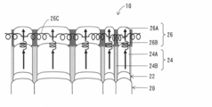
- FIG. 3 is a vertical cross-sectional view schematically showing a part of the vertical cross section of the perpendicular magnetic recording medium 10 according to the present embodiment.
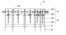
- 3 is a vertical cross-sectional view schematically showing a part of the vertical cross section of the perpendicular magnetic recording medium 10 (state after the cap layer 26 is optimized) according to the present embodiment.
- FIG. 3 is a vertical cross-sectional view schematically showing a part of the vertical cross section of the existing perpendicular magnetic recording medium 100.
- FIG. 3 is a schematic sectional view for explaining the perpendicular magnetic recording medium 10 according to the embodiment of the present invention.
- FIG. 3 is a vertical cross-sectional view schematically showing a part of the vertical cross section of the perpendicular magnetic recording medium 10 according to the present embodiment.
- 3 is a vertical cross-sectional view schematically showing a part of the vertical cross section of
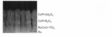
- 20 is a cross-sectional TEM photograph of a region including a cap layer (Co 80 Pt 20 -30 vol% Gd 2 O 3 ) having a thickness of 9 nm (film formation at an argon gas pressure of 0.6 Pa) in Example 17.
- 9 is a TEM photograph of a cross section of a region including a cap layer (Co 80 Pt 20 ⁇ 30 vol% Gd 2 O 3 ) having a thickness of 9 nm in Example 8 (formed at an argon gas pressure of 4.0 Pa).
- 20 is a cross-sectional TEM photograph of a region including a cap layer (CoPtCrB) in the current perpendicular magnetic recording medium (Comparative Example 20).
- Example 16 is a dark-field image taken by a scanning transmission electron microscope (STEM) with respect to a part of the cross-sectional area of Example 17 shown in FIG. It is a photograph which shows the measurement result of the energy dispersive X-ray analysis (EDX) performed by the scanning transmission electron microscope (STEM) about a part of cross-section area
- STEM scanning transmission electron microscope
- FIG. 8 It is a photograph which shows the measurement result of the energy dispersive X-ray analysis (EDX) performed with the scanning transmission electron microscope (STEM) about a part of cross-section area
- STEM scanning transmission electron microscope
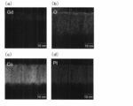
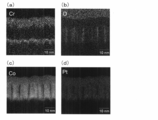
- FIG. 7 is a photograph showing the measurement results of energy dispersive X-ray analysis (EDX) performed by a scanning transmission electron microscope (STEM) on a part of the cross-sectional area of the current perpendicular magnetic recording medium (Comparative Example 20) shown in FIG. Yes, (a) shows the distribution result for Cr, (b) shows the distribution result for O (oxygen), (c) shows the distribution result for Co, and (d) shows the distribution result for Pt. Indicates. 16 is a plane TEM photograph of a region including a cap layer (Co 80 Pt 20 ⁇ 30 vol% Gd 2 O 3 ) of Example 143.
- EDX energy dispersive X-ray analysis
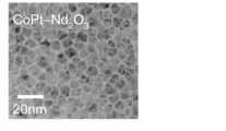
- 16 is a plane TEM photograph of a region including a cap layer (Co 80 Pt 20 ⁇ 30 vol% Nd 2 O 3 ) of Example 144. 16 is a plane TEM photograph of a region including a cap layer (Co 80 Pt 20 ⁇ 30 vol% Sm 2 O 3 ) of Example 145.
- FIG. 1 is a schematic sectional view for explaining a perpendicular magnetic recording medium 10 according to an embodiment of the present invention.
- 2 is a vertical cross-sectional view schematically showing a part of the vertical cross section of the perpendicular magnetic recording medium 10 according to this embodiment
- FIG. 3 is a perpendicular magnetic recording medium 10 (cap layer according to this embodiment).
- 26 is a vertical cross-sectional view schematically showing a part of the vertical cross section after the optimization of FIG. 26).
- the adhesion layer 14, the seed layer 16, the first Ru underlayer 18, and the second Ru underlayer 20 are provided on the substrate 12.
- the buffer layer 22, the perpendicular magnetic recording layer 24, the cap layer 26, and the surface protection layer 28 are sequentially formed.
- a substrate used for various known perpendicular magnetic recording media can be used, and for example, a glass substrate can be used.
- the adhesion layer 14 is a layer for enhancing the adhesion between the seed layer 16 which is a metal film and the substrate 12.
- the adhesion layer 14 for example, a Ta layer or the like can be used.
- the seed layer 16 is a layer for controlling the crystal orientation and crystal growth of the first Ru underlayer 18, and for example, a Ni 90 W 10 layer or the like can be used.
- the first Ru underlayer 18 is a layer for suitably controlling the crystal orientation, crystal grain size, and grain boundary segregation of the perpendicular magnetic recording layer 24.
- the first Ru underlayer 18 has a hexagonal closest packing (hcp) structure.
- the thickness of the first Ru underlayer 18 is, for example, about 10 nm.
- the second Ru underlayer 20 has unevenness on the surface (that is, the surface of the second Ru underlayer 20) of the Ru underlayer having the two-layer structure (the first Ru underlayer 18 and the second Ru underlayer 20). It is a layer for providing a shape so that the buffer layer 22 has a desired layer structure.
- the thickness of the second Ru underlayer 20 is, for example, about 10 nm. If the buffer layer 22 provided on the second Ru foundation layer 20 Ru 50 Co 25 Cr 25 -30vol % TiO 2 layers provided, the protruding portion of the second Ru foundation layer 20 Ru 50 Co 25 Cr 25 is Then, TiO 2 is formed in the concave portion of the second Ru underlayer 20.
- the buffer layer 22 is a layer for improving the separability of columnar CoPt alloy magnetic crystal grains in the granular structure of the perpendicular magnetic recording layer 24.
- the perpendicular magnetic recording layer 24 is a layer for performing magnetic recording, and its layer structure is a granular structure.
- a Co 80 Pt 20 -30vol% B 2 O 3 layer or the like can be used as the perpendicular magnetic recording layer 24.
- the columnar CoPt alloy magnetic crystal grains 24A are non-magnetic grain boundary oxides 24B(B 2 The structure is partitioned by O 3 ) (see FIGS. 2 and 3).
- the thickness of the perpendicular magnetic recording layer 24 is, for example, about 16 nm.
- the cap layer 26 is a layer that covers the perpendicular magnetic recording layer 24, and appropriately adjusts the intergranular exchange coupling between the CoPt alloy magnetic crystal grains 24A of the perpendicular magnetic recording layer 24 to improve the thermal stability of the perpendicular magnetic recording layer 24. It is a layer for improving and reducing the switching magnetic field (the magnetic field necessary for reversing the magnetization of the magnetic crystal grains), and has a granular structure composed of CoPt alloy magnetic crystal grains 26A and magnetic grain boundary oxides 26B (FIG. 2). And FIG. 3).
- the cap layer 26 for example, Co 80 Pt 20 -30vol% magnetic oxide (Gd 2 O 3 , Nd 2 O 3 , Sm 2 O 3 , CeO 2 or the like) can be used, and in this case, a columnar CoPt alloy
- the magnetic crystal grains 26A have a granular structure partitioned by magnetic grain boundary oxides 26B (Gd 2 O 3 , Nd 2 O 3 , Sm 2 O 3 , CeO 2, etc.).
- the thickness of the cap layer 26 is the size required for intergranular exchange coupling between the CoPt alloy magnetic crystal grains 24A of the perpendicular magnetic recording layer 24 and the intergranular exchange coupling 26C of the CoPt alloy magnetic crystal grains 26A of the cap layer 26. It can be appropriately determined according to the size, and is, for example, 1 nm or more and 9 nm or less.
- the surface protective layer 28 is a layer for protecting the surface of the perpendicular magnetic recording medium 10.
- a protective film mainly containing carbon can be used, and its thickness is, for example, 7 nm. Is.
- the cap layer 26 has a granular structure composed of CoPt alloy magnetic crystal grains 26A and magnetic grain boundary oxides 26B.
- the CoPt alloy magnetic crystal grains 26A contain Co at 65 at% or more and 90 at% or less and Pt at 10 at% or more and 35 at% or less.
- the CoPt alloy magnetic crystal grains 26A of the cap layer 26 preferably contain Co at 70 at% or more and 75 at% or less and Pt at 25 at% or more and 30 at% or less. ..
- the CoPt alloy magnetic crystal grains 26A of the cap layer 26 include Co of 70 at% or more and less than 85 at%, Pt of 10 at% or more and 20 at% or less, and Cr, Ti, B, Mo, Ta, Nb, W, and Ru. You may make it contain one or more types of element 0.5 at% or more and 15 at% or less.
- the saturation magnetic field Hs of the perpendicular magnetic recording medium 10 is reduced.
- the volume fraction of the magnetic grain boundary oxide 26B with respect to the entire cap layer 26 is preferably 5 vol% or more and 40 vol% or less, more preferably 10 vol% or more and 35 vol% or less, and 15 vol% or more and 30 vol% or less. Is particularly preferable.
- the volume fraction of the magnetic grain boundary oxide 26B with respect to the entire cap layer 26 may be appropriately determined according to the characteristics required for the perpendicular magnetic recording medium 10.
- the magnetic grain boundary oxide 26B of the cap layer 26 is preferably a rare earth oxide from the viewpoint of increasing magnetism, and specifically, Gd, Nd, Sm, Ce, Eu, La, Pr, Ho, Er. It is preferable to use at least one oxide selected from the oxides of Yb, Yb, and Tb.
- the magnetic grain boundary oxide 26B of the cap layer 26 may not be a rare earth oxide, specifically, for example, magnetic oxide such as: i.e., Fe 2 O 3, Fe 3 O 4, CoFe 2 O 4 , MnTi 0.44 Fe 1.56 O 4 , Mn 0.4 Co 0.3 Fe 2 O 4 , Co 1.1 Fe 2.2 O 4 , Co 0.7 Zn 0.3 Fe 2 O 4 , Ni 0.35 Fe 1.3 O 4 , NiFe 2 O 4 , Li 0.3 Fe 2.5 O 4 , Fe 2.69 Ti 0.31 O 4 , Mn 0.98 Fe 2.02 O 4 , Mn 0.8 Zn 0.2 Fe 2 O 4 , Y 2 Fe 5 O 12 , Y 3 Al 0.83 Fe 4.17 O 12, Y 3 Ga 0.4 Fe 4.6 O 12 , Bi 0.2 Ca 2.8 V 1.4 Fe 3.6 O 12 , Y 1.4 Ca 1.26 V 0.63 Fe 4.37 O 12 , Y 2 Gd 1 Fe 5 O 12 , Y 1.2 Gd 1.8 Fe
- FIG. 2 is a vertical cross-sectional view schematically showing a part of the vertical cross section of the perpendicular magnetic recording medium 10 according to the present embodiment
- FIG. 3 is a vertical cross-sectional view schematically showing a part of the vertical cross section of the perpendicular magnetic recording medium 10 (state after the cap layer 26 is optimized) according to the present embodiment
- FIG. 4 is a vertical sectional view schematically showing a part of the vertical section of the existing perpendicular magnetic recording medium 100.
- the intergranular exchange coupling 26C between the CoPt alloy magnetic crystal grains 26A of the cap layer 26 is schematically represented by a spring-like line.
- the intergranular exchange coupling 102B between the alloy magnetic crystal grains 102A is schematically represented by a spring-shaped line.
- cap layer 26 The effect of the cap layer 26 will be described in detail with reference to FIGS. 2 to 4.
- a Co 80 Pt 20 -30vol% B 2 O 3 layer is used as the perpendicular magnetic recording layer 24. It is assumed that a Co 80 Pt 20 -30vol% Gd 2 O 3 layer is used as the cap layer 26. Further, a Ru 50 Co 25 Cr 25 -30 vol% TiO 2 layer is used as the buffer layer 22. Further, a CoPtCrB alloy is used as the cap layer 102 of the existing perpendicular magnetic recording medium 100.
- the cap layer 26 appropriately adjusts the intergranular exchange coupling between the CoPt alloy magnetic crystal grains 24A of the perpendicular magnetic recording layer 24 to improve the thermal stability of the perpendicular magnetic recording layer 24, and to improve the switching magnetic field (magnetic crystal grains). Is a layer for reducing the magnetic field necessary for reversing the magnetization of the. Since the perpendicular magnetic recording layer 24 itself has a granular structure and the CoPt alloy magnetic crystal grains 24A are partitioned by the non-magnetic grain boundary oxide 24B (B 2 O 3 ), the perpendicular magnetic recording layer 24 itself. In the above, the intergranular exchange coupling between the CoPt alloy magnetic crystal grains 24A is small, so that the thermal stability is insufficient and the reduction of the switching magnetic field is also insufficient.
- the cap layer 26 has a role of compensating for the intergranular exchange coupling between the CoPt alloy magnetic crystal grains 24A, which is insufficient in the perpendicular magnetic recording layer 24 itself. Therefore, in the cap layer 26, the CoPt alloy magnetic crystal is formed. It is necessary to increase the inter-grain exchange coupling 26C between the grains 26A to some extent.
- the magnetic grain boundary oxide 26B is formed by using a magnetic oxide (preferably a rare earth oxide because of its large magnetism) as the oxide. Therefore, the intergranular exchange coupling 26C between the CoPt alloy magnetic crystal grains 26A of the cap layer 26 is increased to some extent, and as a result, the intergranular exchange coupling between the CoPt alloy magnetic crystal grains 24A of the perpendicular magnetic recording layer 24 is performed. Can be appropriately supplemented.
- the intergranular exchange coupling 26C between the CoPt alloy magnetic crystal grains 26A in the cap layer 26 is controlled by the thickness of the cap layer 26. As the thickness of the cap layer 26 increases, the intergranular exchange coupling 26C between the CoPt alloy magnetic crystal grains 26A in the cap layer 26 increases.
- the thickness of the cap layer 26 may be determined according to the required size of the intergranular exchange coupling 26C, but from the viewpoint of not decreasing the coercive force Hc, the thickness of the cap layer 26 is 1 nm or more and 7 nm or less. Is preferred.
- FIG. 4 is a vertical cross-sectional view schematically showing a part of the vertical cross section of the existing perpendicular magnetic recording medium 100.
- the voids 104 are non-magnetic in the perpendicular magnetic recording layer 24. It occurs on the grain boundary oxide 24B (B 2 O 3 ). Since the cap layer 102 of the existing perpendicular magnetic recording medium 100 is a CoPtCrB alloy and does not contain an oxide, it is difficult to wet the non-magnetic grain boundary oxide 24B (B 2 O 3 ) of the perpendicular magnetic recording layer 24, and thus the voids are not formed.
- the cap layer 102 of the existing perpendicular magnetic recording medium 100 has a large non-uniformity in the thickness direction (a non-uniform cross-section when cut at different positions in the thickness direction on a plane orthogonal to the thickness direction). Therefore, even if the thickness of the cap layer 102 is changed, the size of the intergranular exchange coupling 102B between the CoPt alloy magnetic crystal grains 102A of the cap layer 102 does not change exactly in proportion to the thickness. Even if the thickness of the cap layer 102 is controlled, it is difficult to accurately control the size of the intergranular exchange coupling 102B between the CoPt alloy magnetic crystal grains 102A of the cap layer 102.
- the cap layer 26 of the perpendicular magnetic recording medium 10 according to the present embodiment is a Co 80 Pt 20 -30vol% Gd 2 O 3 layer and has a magnetic oxide Gd 2 O 3 . Therefore, a magnetic grain boundary oxide 26B (Gd 2 O 3 ) which easily wets the non-magnetic grain boundary oxide 24B (B 2 O 3 ) of the perpendicular magnetic recording layer 24 is formed, so that a void is generated. Absent. Therefore, the cap layer 26 of the perpendicular magnetic recording medium 10 according to the present embodiment has high uniformity in the thickness direction (the cross section when cut at different positions in the thickness direction on a plane orthogonal to the thickness direction).
- the size of the intergranular exchange coupling 26C between the CoPt alloy magnetic crystal grains 26A of the cap layer 26 changes in proportion to the thickness. Therefore, by controlling the thickness of the cap layer 26, it is possible to accurately control the size of the intergranular exchange coupling 26C between the CoPt alloy magnetic crystal grains 26A of the cap layer 26.
- the cap layer 26 of the perpendicular magnetic recording medium 10 has the granular structure having the CoPt alloy magnetic crystal grains 26A and the magnetic grain boundary oxide 26B, the magnetic grain boundary oxide 26B( Gd 2 O 3 ) has magnetism, and the intergranular exchange coupling 26C between the CoPt alloy magnetic crystal grains 26A in the cap layer 26 is large.
- the cap layer 26 of the perpendicular magnetic recording medium 10 has high uniformity in the thickness direction (the cross section when cut at different positions in the thickness direction on a plane orthogonal to the thickness direction). Therefore, by controlling the thickness of the cap layer 26, it is possible to accurately control the size of the intergranular exchange coupling 26C between the CoPt alloy magnetic crystal grains 26A of the cap layer 26. is there.
- the size of the intergranular exchange coupling 26C between the CoPt alloy magnetic crystal grains 26A in the cap layer 26 is accurately controlled by controlling the thickness of the cap layer 26.
- the magnitude of intergranular exchange coupling between the CoPt alloy magnetic crystal grains 24A of the perpendicular magnetic recording layer 24 can be accurately controlled.
- FIG. 3 is a vertical cross-sectional view schematically showing a part of the vertical cross section of the perpendicular magnetic recording medium 10 (the state after the cap layer 26 is optimized) according to the present embodiment, as described above.
- the thickness of the magnetic grain boundary oxide 26B (Gd 2 O 3 ) in the cross section in the direction orthogonal to the thickness direction is minimized.
- unevenness on the surface of the cap layer 26 is minimized.
- the CoPt alloy magnetic property of the cap layer 26 is reduced.
- the strength of the intergranular exchange coupling 26C between the crystal grains 26A can be increased, and even if the cap layer 26 is thinned, the intergranular exchange coupling 26C between the CoPt alloy magnetic crystal grains 26A of the cap layer 26 is formed. Can be controlled to a certain degree.
- the size of the intergranular exchange coupling 26C between the CoPt alloy magnetic crystal grains 26A in the cap layer 26 can be more accurately determined, and the thickness of the cap layer 26 can be more accurately determined.
- This can be controlled by controlling, and as a result, the magnitude of intergranular exchange coupling between the CoPt alloy magnetic crystal grains 24A of the perpendicular magnetic recording layer 24 can be controlled more accurately.
- the sputtering target used for preparation of the cap layer 26 has the same composition as the cap layer 26 and contains a metal and a magnetic oxide. Specifically, for example, 65 at% or more and 90 at% or less of Co and 10 at% or more and 35 at% or less of Pt are contained with respect to the entire metal, and the magnetic oxidation is performed with respect to the entire sputtering target. Content of 5 vol% or more and 40 vol% or less.
- Co is 70 at% or more and less than 85 at%
- Pt is 10 at% or more and 20 at% or less
- 0.5 at% or more and 15 at% or less is contained, and 5 vol% or more and 40 vol% or less of the magnetic oxide is contained in the whole sputtering target.
- the sputtering target has a composition of Co 80 Pt 20 -30vol% Gd 2 O 3. Will be explained.
- the manufacturing method of the sputtering target used for manufacturing the cap layer 26 is not limited to the following specific examples.
- the metal Co and the metal Pt are weighed so that the atomic ratio of the metallic Co to the total of the metallic Co and the metallic Pt is 80 at% and the atomic ratio of the metallic Pt is 20 at% to prepare a molten CoPt alloy. Then, gas atomization is performed to produce CoPt alloy atomized powder. The produced CoPt alloy atomized powder is classified so that the particle diameter becomes equal to or smaller than a predetermined particle diameter (for example, 106 ⁇ m or less).
- a predetermined particle diameter for example, 106 ⁇ m or less.
- Gd 2 O 3 powder is added to the prepared CoPt alloy atomized powder so as to be 30 vol %, and mixed and dispersed by a ball mill to prepare a mixed powder for pressure sintering.
- a mixed powder for pressure sintering in which the CoPt alloy atomized powder and the Gd 2 O 3 powder are finely dispersed can be produced.
- the saturation magnetic field Hs of the perpendicular magnetic recording medium 10 is increased by increasing the coercive force Hc of the perpendicular magnetic recording medium 10 and increasing the intergranular exchange coupling 26C of the CoPt alloy magnetic crystal grains 26A of the cap layer 26.
- the volume fraction for the entire cap layer 26 of the magnetic grain boundary oxide 26B is less 5 vol% or more 40vol%, Gd 2 O 3 total pressure sintering mixed powder for powder It is preferable that the volume fraction with respect to is 5 vol% or more and 40 vol% or less.
- the prepared mixed powder for pressure sintering is pressure-sintered by, for example, a vacuum hot press method, and molded to prepare a sputtering target.
- the prepared powder mixture for pressure sintering was mixed and dispersed by a ball mill, and the CoPt alloy atomized powder and the Gd 2 O 3 powder were finely dispersed. Therefore, the sputtering target obtained by this manufacturing method was used. When sputtering is performed, problems such as generation of nodules and particles are unlikely to occur.
- the method for pressure-sintering the mixed powder for pressure sintering is not particularly limited, and a method other than the vacuum hot pressing method may be used, for example, the HIP method or the like may be used.
- a CoPt alloy atomized powder is manufactured by using the atomization method, Gd 2 O 3 powder is added to the manufactured CoPt alloy atomized powder, and the mixture is mixed and dispersed in a ball mill, and pressure sintering is performed.
- the mixed powder for use is prepared, Co simple powder and Pt simple powder may be used instead of the CoPt alloy atomized powder.
- Co simple powder, Pt simple powder and Gd 2 O 3 powder are mixed and dispersed by a ball mill to prepare a mixed powder for pressure sintering.
- Examples 1 to 142, Comparative Examples 1 to 20 A layer structure similar to that of FIG. 1 (on the substrate 12, the adhesion layer 14, the seed layer 16, the first Ru underlayer 18, the second Ru underlayer 20, the buffer layer 22, the perpendicular magnetic recording layer 24, the cap layer 26). , And the surface protection layer 28 are sequentially formed) to prepare perpendicular magnetic recording media of Examples 1 to 142 and Comparative Examples 2 to 20. Specifically, it was done as follows.
- a glass substrate was used as the substrate 12.
- a Ta layer having a thickness of 5 nm was formed under the conditions of an argon gas pressure of 0.6 Pa and an input power of 500 W.
- a Ni 90 W 10 layer was formed to a thickness of 6 nm under the conditions of an argon gas pressure of 0.6 Pa and an input power of 500 W.
- a Ru layer having a thickness of 10 nm was formed under the conditions of an argon gas pressure of 0.6 Pa and an input power of 500 W.
- a Ru layer having a thickness of 10 nm was formed under the conditions of an argon gas pressure of 8.0 Pa and an input power of 500 W.
- a Ru 50 Co 25 Cr 25 -30 vol% TiO 2 layer having a thickness of 2 nm was formed under the conditions of an argon gas pressure of 0.6 Pa and an input power of 300 W.
- a Co 80 Pt 20 -30 vol% B 2 O 3 layer having a thickness of 16 nm was formed under the conditions of an argon gas pressure of 4.0 Pa and an input power of 500 W.
- an argon gas pressure of 0.6 Pa or 4.0 Pa and an input power of 500 W are used by using the sputtering target manufactured as described in the above “(4) Sputtering target used for manufacturing cap layer 26”. Under the conditions, a CoPt alloy-magnetic grain boundary oxide was formed into a film with the composition and thickness shown in Tables 1 to 4.
- carbon was deposited to a thickness of 7 nm under the conditions of an argon gas pressure of 0.6 Pa and an input power of 300 W.
- Comparative Example 1 a perpendicular magnetic recording medium having a configuration in which the cap layer 26 was removed in the above configuration was manufactured.
- Comparative Example 20 is a comparative example in which the cap layer (CoPtCrB) of the existing perpendicular magnetic recording medium is used for the cap layer.
- the magnetic properties of the sample vibrating magnetometer (Squid-VSM) using a superconducting quantum interference device (manufacturing company: QUANTUM DESIGN, Part number name, MPMS3), high-sensitivity magnetic anisotropy torque meter (torque magnetometer) (manufacturing company: Tamagawa Seisakusho, part number name: TM-TR2050-HGC), magneto-optical Kerr effect measurement device (Magneto Optical Kerr Effect (MOKE)) ) was used for the measurement. Further, the microstructures of the cap layers of the fabricated perpendicular magnetic recording media of Examples 1 to 142 and Comparative Examples 1 to 20 were observed using a planar TEM-EDX and a cross-sectional TEM-EDX.
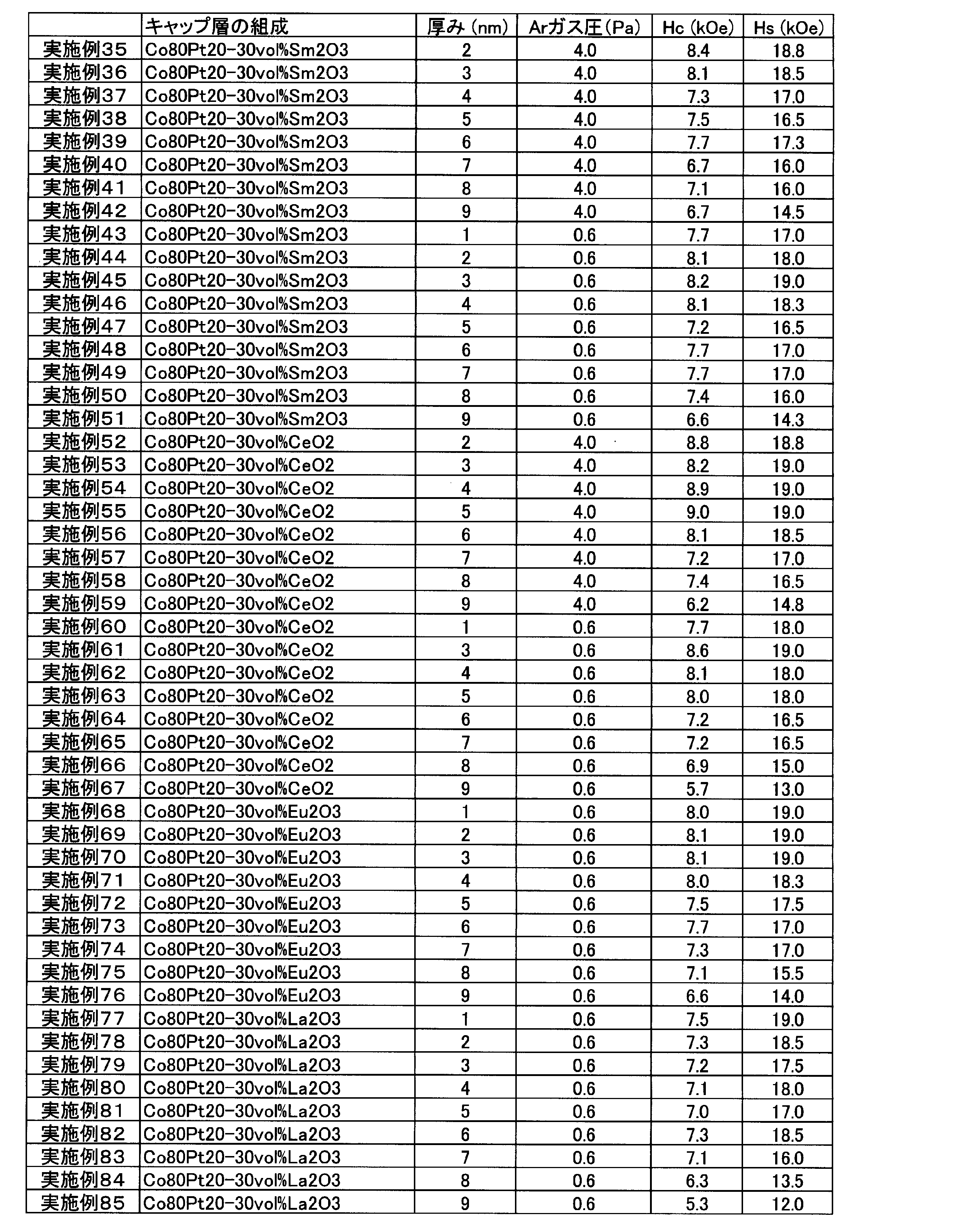
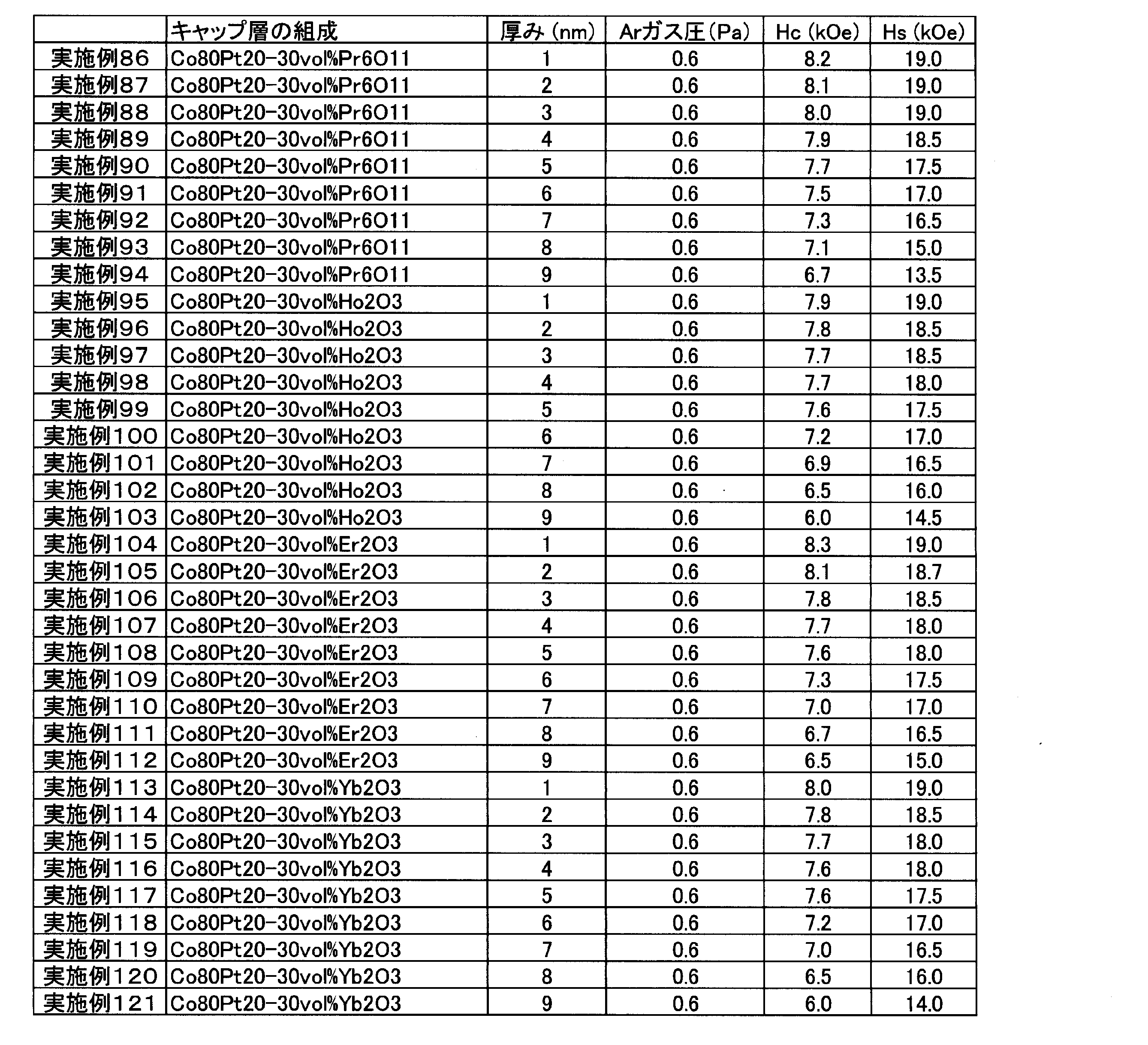
- Tables 1 to 4 below show coercive force Hc and saturation magnetic field Hs measured for the perpendicular magnetic recording media of Examples 1 to 142 and Comparative Examples 1 to 20.
- the coercive force Hc and the saturation magnetic field Hs were obtained from a hysteresis loop measured using a sample vibrating magnetometer (Squid-VSM).
- the thickness indicates the thickness of the cap layer
- the Ar gas pressure indicates the argon gas pressure at the time of forming the cap layer.
- the coercive force Hc is 5 kOe or more, and the saturation magnetic field Hs is less than 20 kOe.
- the coercive force Hc is less than 5 kOe or the saturation magnetic field Hs is 20 kOe or more.
- the thermal stability is insufficient, and if the saturation magnetic field Hs is 20 kOe or more, the switching magnetic field is too large and the magnetic recording is insufficient.
- Example 143-159 Comparative Example 21
- samples were prepared by changing the composition of the cap layer, the activated particle size GD act of the cap layer was measured, and the thermal stability of the cap layer was evaluated.
- the perpendicular magnetic recording layer 24 was not provided, and the cap layer 26 having a thickness of 16 nm was provided on the buffer layer 22.
- a sample was prepared in the same manner as in Examples 1 to 142.
- the film forming conditions for providing the cap layer 26 having a thickness of 16 nm on the buffer layer 22 were an argon gas pressure of 4.0 Pa and an input power of 500 W.
- the activated particle size GD act was measured using a magneto-optical Kerr effect (MOKE) device.
- MOKE magneto-optical Kerr effect
- B 2 O 3 used in Comparative Example 21 is the oxide used in Comparative Examples 2 to 14, and Gd 2 O 3 used in Examples 143 and 153 to 159 is Examples 1 to 17 and 122 to 142.
- the oxide used in Examples 15 to 19 Nd 2 O 3 used in Example 144 is the oxide used in Examples 18 to 34, and the Sm 2 O 3 used in Example 145 is Example 35.
- the CeO 2 used in Examples 146 is the oxide used in Examples 52 to 67, and the Eu 2 O 3 used in Examples 147 is used in Examples 68 to 76.
- La 2 O 3 used in Examples 148 is the oxide used in Examples 77 to 85
- Pr 6 O 11 used in Examples 149 is the oxide used in Examples 86 to 94
- Ho 2 O 3 used in Example 150 is the oxide used in Examples 95 to 103
- Er 2 O 3 used in Example 151 is the oxide used in Examples 104 to 112. Therefore, Yb 2 O 3 used in Example 152 is the oxide used in Examples 113 to 121.
- Examples 143 and 153 to 159 are examples in which the volume fraction of Gd 2 O 3 was changed within the range of 5 to 40 vol %.
- the non-magnetic oxide was only B 2 O 3 of Comparative Example 21, and the oxides of Examples 143 to 159 (Gd 2 O 3 , Nd 2 O 3 , Sm 2 O 3) were used.
- CeO 2 , Eu 2 O 3 , La 2 O 3 , Pr 6 O 11 , Ho 2 O 3 , Er 2 O 3 , Yb 2 O 3 ) are magnetic oxides.
- the activation particle size GD act of the cap layer using B 2 O 3 which is a non-magnetic oxide is 6.5 nm.
- magnetic oxides Gd 2 O 3 , Nd 2 O 3 , Sm 2 O 3 , CeO 2 , Eu 2 O 3 , La 2 O 3 , Pr 6 O 11 , Ho 2 O 3 , Er 2
- the activation particle size GD act of the cap layer using O 3 and Yb 2 O 3 is 8.5 to 10.5 nm, and the activation particle of the cap layer using B 2 O 3 which is a non-magnetic oxide.
- the diameter is larger than GD act by 30% or more, and the magnetic oxides (Gd 2 O 3 , Nd 2 O 3 , Sm 2 O 3 , CeO 2 , Eu 2 O 3 , La 2 O 3 , Pr 6 O 11 , Ho 2 O 3, Er 2 O 3, Yb 2 O 3) capping layer with is considered to have excellent thermal stability.
- FIG. 5 is a cross-sectional TEM photograph of a region including a cap layer (Co 80 Pt 20 ⁇ 30 vol% Gd 2 O 3 ) having a thickness of 9 nm (formed at an argon gas pressure of 0.6 Pa) in Example 17.
- FIG. 7 is a cross-sectional TEM photograph of a region including a cap layer (Co 80 Pt 20 ⁇ 30 vol% Gd 2 O 3 ) having a thickness of 9 nm (formed at an argon gas pressure of 4.0 Pa) in Example 8
- FIG. 20 is a cross-sectional TEM photograph of a region including a cap layer (CoPtCrB) in the current perpendicular magnetic recording medium (Comparative Example 20).
- FIG. 8 is a dark-field image of a part of the cross-sectional area of Example 17 shown in FIG. 5 taken by a scanning transmission electron microscope (STEM), and FIG. 9 is a dark field image of Example 17 shown in FIG. It is a photograph which shows the measurement result of the energy dispersive X-ray analysis (EDX) performed with the scanning transmission electron microscope (STEM) about a part of cross section area.
- 10 is a dark-field image of a part of the cross-sectional area of Example 8 shown in FIG. 6 taken with a scanning transmission electron microscope (STEM), and FIG. 11 is a cross-sectional area of Example 8 shown in FIG.
- FIG. 3 is a photograph showing a measurement result of energy dispersive X-ray analysis (EDX) performed by a scanning transmission electron microscope (STEM) for a part of the above.
- 12 is a dark-field image of a part of the cross-sectional area of the current perpendicular magnetic recording medium (Comparative Example 20) shown in FIG. 7, taken by a scanning transmission electron microscope (STEM), and
- FIG. 6 is a photograph showing the measurement results of energy dispersive X-ray analysis (EDX) performed by a scanning transmission electron microscope (STEM) on a part of the cross-sectional area of the current perpendicular magnetic recording medium (Comparative Example 20) shown in FIG.
- Example 17 in which a cap layer was formed to a thickness of 9 nm at an argon gas pressure of 0.6 Pa and a cap layer to a thickness of 9 nm at an argon gas pressure of 4.0 Pa.
- the film was formed, no void was formed on the nonmagnetic grain boundary oxide 24B (B 2 O 3 ) of the perpendicular magnetic recording layer 24, and the perpendicular magnetic recording layer (CoPt- The boundary between the B 2 O 3 layer) and the cap layer (Co 80 Pt 20 -30vol% Gd 2 O 3 ) is flat.
- the shape of the CoPt alloy magnetic crystal grains in the perpendicular magnetic recording layer can be estimated from the distribution states of Co and Pt shown in FIGS. 9, 11 and 13.
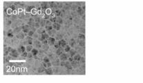
- Plant TEM photograph 14 is a plane TEM photograph of a region including a cap layer (Co 80 Pt 20 -30 vol% Gd 2 O 3 ) of Example 143, and FIG. 15 is a cap layer (Co 80 Pt 20 -30 vol) of Example 144.
- 16 is a plane TEM photograph of a region containing %Nd 2 O 3 ), and FIG. 16 is a plane TEM photograph of a region containing a cap layer (Co 80 Pt 20 ⁇ 30 vol% Sm 2 O 3 ) of Example 145.
- the perpendicular magnetic recording medium according to the present invention is provided with a cap layer having excellent characteristics (characteristics that improve the thermal stability of the perpendicular magnetic recording medium and reduce the switching magnetic field) as compared with the existing cap layer, and the thermal stability is improved. It has improved industrial properties and reduced switching magnetic field, and has industrial applicability.
Landscapes
- Physics & Mathematics (AREA)
- Spectroscopy & Molecular Physics (AREA)
- Magnetic Record Carriers (AREA)
- Paints Or Removers (AREA)
Abstract
Description
本実施形態に係る垂直磁気記録媒体10は、基板12上に、付着層14、シード層16、第1のRu下地層18、第2のRu下地層20、バッファ層22、垂直磁気記録層24、キャップ層26、および表面保護層28を順次形成して成る構成を有する。
キャップ層26は、前述したように、CoPt合金磁性結晶粒26Aと磁性粒界酸化物26Bとからなるグラニュラ構造を有するが、キャップ層26のCoPt合金磁性結晶粒26Aは、Coを65at%以上90at%以下、Ptを10at%以上35at%以下含有する。垂直磁気記録媒体10の保磁力Hcをより大きくする観点から、キャップ層26のCoPt合金磁性結晶粒26Aは、Coを70at%以上75at%以下、Ptを25at%以上30at%以下含有することが好ましい。
前述したように、図2は、本実施形態に係る垂直磁気記録媒体10の垂直断面の一部を模式的に示す垂直断面図であり、図3は、本実施形態に係る垂直磁気記録媒体10(キャップ層26を最適化した後の状態)の垂直断面の一部を模式的に示す垂直断面図である。また、図4は、現行の垂直磁気記録媒体100の垂直断面の一部を模式的に示す垂直断面図である。なお、図2および図3において、キャップ層26のCoPt合金磁性結晶粒26A同士の粒間交換結合26Cは、バネ状の線で模式的に表現し、同様に図4において、キャップ層102のCoPt合金磁性結晶粒102A同士の粒間交換結合102Bは、バネ状の線で模式的に表現している。
(4-1)スパッタリングターゲットの組成
キャップ層26の作製に用いるスパッタリングターゲットは、キャップ層26と同様の組成を有し、金属および磁性酸化物を含有しており、具体的には例えば、前記金属の全体に対して、Coを65at%以上90at%以下、Ptを10at%以上35at%以下含有し、前記スパッタリングターゲットの全体に対して、前記磁性酸化物を5vol%以上40vol%以下含有する。また、具体的には例えば、金属の全体に対して、Coを70at%以上85at%未満、Ptを10at%以上20at%以下、Cr、Ti、B、Mo、Ta、Nb、W、Ruのうちの1種以上の元素を0.5at%以上15at%以下含有し、前記スパッタリングターゲットの全体に対して、前記磁性酸化物を5vol%以上40vol%以下含有する。
次に、キャップ層26の作製に用いるスパッタリングターゲットの製造方法について説明するが、ここでは、組成がCo80Pt20-30vol%Gd2O3であるスパッタリングターゲットを取り上げて説明する。ただし、キャップ層26の作製に用いるスパッタリングターゲットの製造方法が以下の具体例に限定されるわけではない。
図1と同様の層構成(基板12上に、付着層14、シード層16、第1のRu下地層18、第2のRu下地層20、バッファ層22、垂直磁気記録層24、キャップ層26、および表面保護層28を順次形成する層構成)で、実施例1~142、比較例2~20の垂直磁気記録媒体を作製した。具体的には、次のようにした。


実施例143~159、比較例21においてはキャップ層の組成を変えてサンプルの作製を行い、キャップ層の活性化粒径GDactを測定して、キャップ層の熱安定性の評価を行った。実施例143~159、比較例21のサンプルにおいては、垂直磁気記録層24は設けておらず、バッファ層22の上に厚さ16nmのキャップ層26を設けた。それ以外の点は、実施例1~142と同様にしてサンプルの作製を行った。なお、バッファ層22の上に厚さ16nmのキャップ層26を設ける際の成膜条件は、アルゴンガス圧4.0Pa、投入電力500Wとした。
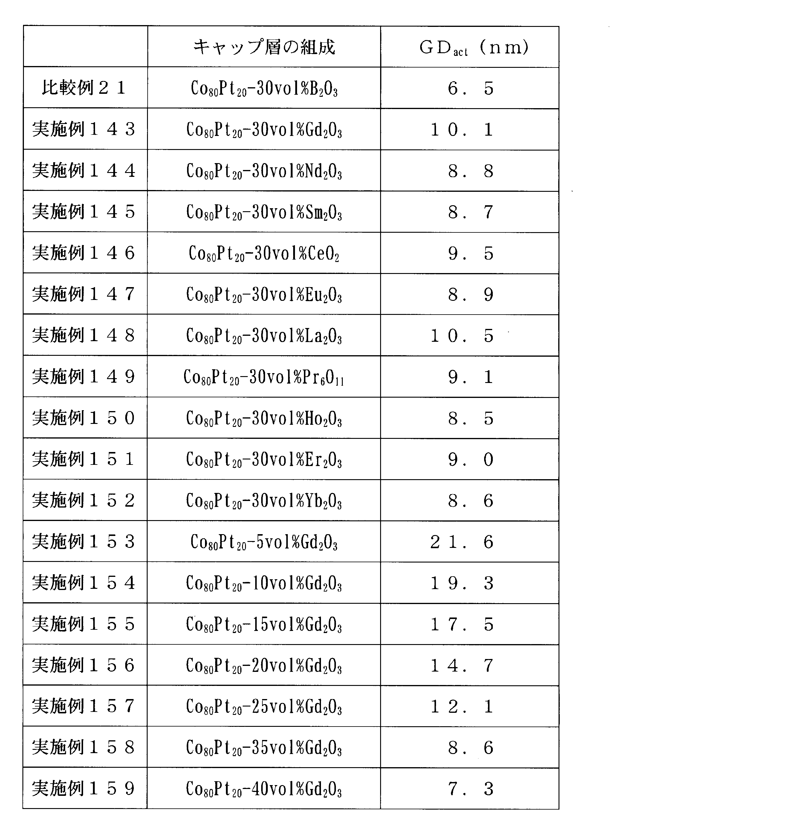
図5は、実施例17の厚さ9nmのキャップ層(Co80Pt20-30vol%Gd2O3)(アルゴンガス圧0.6Paで成膜)を含む領域の断面TEM写真であり、図6は、実施例8の厚さ9nmのキャップ層(Co80Pt20-30vol%Gd2O3)(アルゴンガス圧4.0Paで成膜)を含む領域の断面TEM写真であり、図7は、現行の垂直磁気記録媒体(比較例20)において、キャップ層(CoPtCrB)を含む領域の断面TEM写真である。
図14は、実施例143のキャップ層(Co80Pt20-30vol%Gd2O3)を含む領域の平面TEM写真であり、図15は、実施例144のキャップ層(Co80Pt20-30vol%Nd2O3)を含む領域の平面TEM写真であり、図16は、実施例145のキャップ層(Co80Pt20-30vol%Sm2O3)を含む領域の平面TEM写真である。
12…基板
14…付着層
16…シード層
18…第1のRu下地層
20…第2のRu下地層
22…バッファ層
24…垂直磁気記録層
24A、26A…CoPt合金磁性結晶粒
24B…非磁性粒界酸化物
26…キャップ層
26B…磁性粒界酸化物
26C…粒間交換結合
28…表面保護層
Claims (4)
- 垂直磁気記録層および前記垂直磁気記録層を覆うキャップ層を備える垂直磁気記録媒体であって、
前記垂直磁気記録層は、CoPt合金磁性結晶粒と非磁性粒界酸化物とからなるグラニュラ構造を有し、
前記キャップ層は、CoPt合金磁性結晶粒と磁性粒界酸化物とからなるグラニュラ構造を有し、
前記キャップ層の前記CoPt合金磁性結晶粒は、Coを65at%以上90at%以下、Ptを10at%以上35at%以下含有し、
前記磁性粒界酸化物の前記キャップ層全体に対する体積分率は5vol%以上40vol%以下であることを特徴とする垂直磁気記録媒体。 - 垂直磁気記録層および前記垂直磁気記録層を覆うキャップ層を備える垂直磁気記録媒体であって、
前記垂直磁気記録層は、CoPt合金磁性結晶粒と非磁性粒界酸化物とからなるグラニュラ構造を有し、
前記キャップ層は、CoPt合金磁性結晶粒と磁性粒界酸化物とからなるグラニュラ構造を有し、
前記キャップ層の前記CoPt合金磁性結晶粒は、Coを70at%以上85at%未満、Ptを10at%以上20at%以下、Cr、Ti、B、Mo、Ta、Nb、W、Ruのうちの1種以上の元素を0.5at%以上15at%以下含有し、
前記磁性粒界酸化物の前記キャップ層全体に対する体積分率は5vol%以上40vol%以下であることを特徴とする垂直磁気記録媒体。 - 前記磁性粒界酸化物は、希土類酸化物であることを特徴とする請求項1または2に記載の垂直磁気記録媒体。
- 前記磁性粒界酸化物は、Gd、Nd、Sm、Ce、Eu、La、Pr、Ho、Er、Yb、Tbの酸化物のうちの1種以上の酸化物であることを特徴とする請求項1または2に記載の垂直磁気記録媒体。
Priority Applications (3)
| Application Number | Priority Date | Filing Date | Title |
|---|---|---|---|
| SG11202106231YA SG11202106231YA (en) | 2019-01-11 | 2019-12-23 | Perpendicular magnetic recording medium |
| US17/422,369 US20220122635A1 (en) | 2019-01-11 | 2019-12-23 | Perpendicular magnetic recording medium |
| CN201980083935.1A CN113196392B (zh) | 2019-01-11 | 2019-12-23 | 垂直磁记录介质 |
Applications Claiming Priority (2)
| Application Number | Priority Date | Filing Date | Title |
|---|---|---|---|
| JP2019003874A JP7125061B2 (ja) | 2019-01-11 | 2019-01-11 | 垂直磁気記録媒体 |
| JP2019-003874 | 2019-01-11 |
Publications (1)
| Publication Number | Publication Date |
|---|---|
| WO2020145114A1 true WO2020145114A1 (ja) | 2020-07-16 |
Family
ID=71520353
Family Applications (1)
| Application Number | Title | Priority Date | Filing Date |
|---|---|---|---|
| PCT/JP2019/050388 Ceased WO2020145114A1 (ja) | 2019-01-11 | 2019-12-23 | 垂直磁気記録媒体 |
Country Status (6)
| Country | Link |
|---|---|
| US (1) | US20220122635A1 (ja) |
| JP (1) | JP7125061B2 (ja) |
| CN (1) | CN113196392B (ja) |
| SG (1) | SG11202106231YA (ja) |
| TW (1) | TWI778318B (ja) |
| WO (1) | WO2020145114A1 (ja) |
Citations (4)
| Publication number | Priority date | Publication date | Assignee | Title |
|---|---|---|---|---|
| JP2008146816A (ja) * | 2006-12-07 | 2008-06-26 | Hitachi Global Storage Technologies Netherlands Bv | 粒間交換強化層を含む多層記録構造を備えた垂直磁気記録媒体 |
| JP2009110641A (ja) * | 2007-10-07 | 2009-05-21 | Hoya Corp | 垂直磁気記録媒体 |
| JP2009187652A (ja) * | 2008-02-01 | 2009-08-20 | Samsung Electronics Co Ltd | 垂直磁気記録媒体 |
| JP2010257564A (ja) * | 2009-03-31 | 2010-11-11 | Wd Media Singapore Pte Ltd | 垂直磁気記録媒体 |
Family Cites Families (15)
| Publication number | Priority date | Publication date | Assignee | Title |
|---|---|---|---|---|
| JP2001014649A (ja) * | 1999-06-28 | 2001-01-19 | Hitachi Ltd | 板状体、無機化合物基板、磁気記録媒体及び磁気記憶装置 |
| JP4332833B2 (ja) * | 2001-08-31 | 2009-09-16 | 富士電機デバイステクノロジー株式会社 | 垂直磁気記録媒体及びその製造方法 |
| US8110298B1 (en) * | 2005-03-04 | 2012-02-07 | Seagate Technology Llc | Media for high density perpendicular magnetic recording |
| US20060234091A1 (en) * | 2005-04-19 | 2006-10-19 | Heraeus, Inc. | Enhanced multi-component oxide-containing sputter target alloy compositions |
| US7678476B2 (en) * | 2006-01-20 | 2010-03-16 | Seagate Technology Llc | Composite heat assisted magnetic recording media with temperature tuned intergranular exchange |
| CN101197139A (zh) * | 2006-12-05 | 2008-06-11 | 希捷科技有限公司 | 通过蚀刻帽层和前置防护涂层而提高抗腐蚀性的颗粒状磁记录介质 |
| US7998607B2 (en) * | 2009-07-31 | 2011-08-16 | Hitachi Global Storage Technologies Netherlands, B.V. | Partially-oxidized cap layer for hard disk drive magnetic media |
| US20120127609A1 (en) * | 2010-11-18 | 2012-05-24 | Hitachi Global Storage Technologies Netherlands B.V. | System, method and apparatus for perpendicular magnetic recording media having decoupled control and graded anisotropy |
| US8507114B2 (en) * | 2011-06-30 | 2013-08-13 | Seagate Technology Llc | Recording layer for heat assisted magnetic recording |
| US8614862B1 (en) * | 2012-12-21 | 2013-12-24 | HGST Netherlands B.V. | Perpendicular magnetic recording media having a cap layer above a granular layer |
| US9799363B2 (en) * | 2013-03-13 | 2017-10-24 | Seagate Technology, Llc | Damping controlled composite magnetic media for heat assisted magnetic recording |
| JP2015087510A (ja) * | 2013-10-30 | 2015-05-07 | 日本電信電話株式会社 | 光モジュールの作製方法 |
| US10020016B2 (en) * | 2013-12-10 | 2018-07-10 | Fuji Electric Co., Ltd. | Perpendicular magnetic recording medium |
| MY192454A (en) * | 2016-11-01 | 2022-08-21 | Tanaka Precious Metal Ind | Sputtering target for magnetic recording media |
| US10923147B2 (en) * | 2018-04-20 | 2021-02-16 | Western Digital Technologies, Inc. | Magnetic media design with multiple non-magnetic exchange control layers |
-
2019
- 2019-01-11 JP JP2019003874A patent/JP7125061B2/ja active Active
- 2019-12-23 CN CN201980083935.1A patent/CN113196392B/zh not_active Expired - Fee Related
- 2019-12-23 WO PCT/JP2019/050388 patent/WO2020145114A1/ja not_active Ceased
- 2019-12-23 SG SG11202106231YA patent/SG11202106231YA/en unknown
- 2019-12-23 US US17/422,369 patent/US20220122635A1/en not_active Abandoned
- 2019-12-31 TW TW108148510A patent/TWI778318B/zh active
Patent Citations (4)
| Publication number | Priority date | Publication date | Assignee | Title |
|---|---|---|---|---|
| JP2008146816A (ja) * | 2006-12-07 | 2008-06-26 | Hitachi Global Storage Technologies Netherlands Bv | 粒間交換強化層を含む多層記録構造を備えた垂直磁気記録媒体 |
| JP2009110641A (ja) * | 2007-10-07 | 2009-05-21 | Hoya Corp | 垂直磁気記録媒体 |
| JP2009187652A (ja) * | 2008-02-01 | 2009-08-20 | Samsung Electronics Co Ltd | 垂直磁気記録媒体 |
| JP2010257564A (ja) * | 2009-03-31 | 2010-11-11 | Wd Media Singapore Pte Ltd | 垂直磁気記録媒体 |
Also Published As
| Publication number | Publication date |
|---|---|
| US20220122635A1 (en) | 2022-04-21 |
| JP7125061B2 (ja) | 2022-08-24 |
| SG11202106231YA (en) | 2021-07-29 |
| CN113196392B (zh) | 2022-10-18 |
| CN113196392A (zh) | 2021-07-30 |
| JP2020113353A (ja) | 2020-07-27 |
| TWI778318B (zh) | 2022-09-21 |
| TW202031916A (zh) | 2020-09-01 |
Similar Documents
| Publication | Publication Date | Title |
|---|---|---|
| US6210544B1 (en) | Magnetic film forming method | |
| TW479075B (en) | Sputtering target and antiferromagnetic film and magneto-resistance effect element formed by using the same | |
| JP3411626B2 (ja) | 磁性多層膜および磁気抵抗効果素子ならびにそれらの製造方法 | |
| US10971181B2 (en) | Sputtering target for magnetic recording media | |
| EP0883196B1 (en) | Magnetoresistance effect film and magnetoresistance effect type head | |
| US9053910B2 (en) | Magnetron sputtering target and process for producing the same | |
| CN113228208B (zh) | 面内磁化膜、面内磁化膜多层结构、硬偏置层、磁阻效应元件和溅射靶 | |
| WO2020027235A1 (ja) | 磁気記録媒体用スパッタリングターゲット | |
| KR20060054100A (ko) | 수직 자기 기록 매체 | |
| JP6618298B2 (ja) | 超高周波強磁性薄膜とその製造方法 | |
| WO2019187520A1 (ja) | スパッタリングターゲット | |
| WO2020145114A1 (ja) | 垂直磁気記録媒体 | |
| WO2021014760A1 (ja) | 非磁性層形成用スパッタリングターゲット部材 | |
| Tsunoda et al. | Enhancement of exchange bias by ultra‐thin Mn layer insertion at the interface of Mn‐Ir/Co‐Fe bilayers | |
| JP2010067769A (ja) | 磁気抵抗膜ならびに磁気抵抗膜を用いた磁気記録用磁気ヘッド、磁気センサ及び磁気メモリー | |
| JP3956061B2 (ja) | 一軸磁気異方性膜 | |
| JP7438845B2 (ja) | 面内磁化膜、面内磁化膜多層構造、ハードバイアス層、および磁気抵抗効果素子 | |
| JPH1092639A (ja) | 高電気抵抗を有する磁気抵抗膜 | |
| TW201915204A (zh) | 濺鍍靶、積層膜之製造方法、積層膜及磁記錄媒體 | |
| Liu et al. | FePt–Si–N nano-granular thin films with improved structure and magnetic properties for high-density recording medium | |
| JP3337732B2 (ja) | 磁気抵抗効果素子 | |
| CN115461882A (zh) | 面内磁化膜、面内磁化膜多层结构、硬偏置层、磁阻效应元件和溅射靶 | |
| Shintaku et al. | Effect of Additives and Underlayers on the Soft Magnetic Properties of High-Bs Fe-Co Films | |
| WO2020053972A1 (ja) | スパッタリングターゲット、磁性膜および、磁性膜の製造方法 | |
| JPH07235034A (ja) | 垂直磁気記録媒体および磁気記録再生装置 |
Legal Events
| Date | Code | Title | Description |
|---|---|---|---|
| 121 | Ep: the epo has been informed by wipo that ep was designated in this application |
Ref document number: 19908289 Country of ref document: EP Kind code of ref document: A1 |
|
| NENP | Non-entry into the national phase |
Ref country code: DE |
|
| 122 | Ep: pct application non-entry in european phase |
Ref document number: 19908289 Country of ref document: EP Kind code of ref document: A1 |
|
| WWG | Wipo information: grant in national office |
Ref document number: 11202106231Y Country of ref document: SG |
|
| WWP | Wipo information: published in national office |
Ref document number: 11202106231Y Country of ref document: SG |