WO2020144952A1 - 照明装置および表示装置 - Google Patents
照明装置および表示装置 Download PDFInfo
- Publication number
- WO2020144952A1 WO2020144952A1 PCT/JP2019/046000 JP2019046000W WO2020144952A1 WO 2020144952 A1 WO2020144952 A1 WO 2020144952A1 JP 2019046000 W JP2019046000 W JP 2019046000W WO 2020144952 A1 WO2020144952 A1 WO 2020144952A1
- Authority
- WO
- WIPO (PCT)
- Prior art keywords
- light
- light source
- guide plate
- emitted
- lighting device
- Prior art date
- Legal status (The legal status is an assumption and is not a legal conclusion. Google has not performed a legal analysis and makes no representation as to the accuracy of the status listed.)
- Ceased
Links
Images







Classifications
-
- F—MECHANICAL ENGINEERING; LIGHTING; HEATING; WEAPONS; BLASTING
- F21—LIGHTING
- F21S—NON-PORTABLE LIGHTING DEVICES; SYSTEMS THEREOF; VEHICLE LIGHTING DEVICES SPECIALLY ADAPTED FOR VEHICLE EXTERIORS
- F21S2/00—Systems of lighting devices, not provided for in main groups F21S4/00 - F21S10/00 or F21S19/00, e.g. of modular construction
Definitions
- Embodiments of the present invention relate to a lighting device and a display device.
- a display device such as a liquid crystal display device includes a display panel having pixels and an illumination device such as a backlight that illuminates the display panel.
- the illumination device includes a light source that emits light and a light guide plate that is irradiated with light from the light source. The light from the light source enters the light guide plate from the end portion of the light guide plate, propagates in the light guide plate, and is emitted from the emission surface corresponding to one main surface of the light guide plate.
- Patent Document 1 there is also known an illuminating device in which light sources are arranged near both ends of a light guide plate.
- Patent Document 2 there has been proposed an illuminating device in which light sources that emit laser light are arranged near both ends of a light guide plate. In such a configuration, the light from one light source mainly exits from the region of the light guide plate near the other light source.
- the brightness of light emitted from the light source from the light source greatly differs between the area near the light source and the area far from the light source. Therefore, when the positional relationship between the region where the light from one light source is strongly emitted and the region where the light from the other light source is strongly emitted is deviated, a dark line or a bright line may occur in the central portion of the light guide plate.
- One of the objects of the present invention is to provide an illuminating device capable of irradiating light having a good luminance distribution from the exit surface of the light guide plate and a display device including the illuminating device.
- An illumination device includes a first light source and a second light source that emit laser light, a first end portion that is irradiated with light from the first light source, and a first light source that is irradiated with light from the second light source.
- a light guide plate having two end portions, a first surface that reflects the light incident from the first end portion and the second end portion, and a second surface that emits the light reflected by the first surface. I have it.
- the light guide plate is located between the first end portion and the second end portion, and between the first end portion and the center portion, and the light from the second light source is the first portion.
- the brightness when the light from the first light source is emitted from the second surface gradually increases from the first end side toward the second end side, and the second end From the side to the first end side, the brightness gradient characteristic is such that the brightness when the light from the second light source is emitted from the second surface is sequentially increased.
- a display device includes the lighting device and a display panel that faces the second surface and displays an image using light emitted from the second surface.
- FIG. 1 is a perspective view showing a schematic configuration of the display device according to the first embodiment.
- FIG. 2 is a schematic cross-sectional view of the display device according to the first embodiment.
- FIG. 3 is a schematic plan view of the lighting device according to the first embodiment.
- FIG. 4 is a plan view for explaining the relationship between the light emitted by the first light source and the luminance of the second surface in the lighting device according to the first embodiment.
- FIG. 5 is a graph showing an example of the brightness of light emitted from the light guide plate according to the first embodiment.
- FIG. 6 is a graph showing another example of the brightness of light emitted from the light guide plate according to the first embodiment.
- FIG. 7 is a plan view of the second surface schematically showing the luminance distribution of the combined light shown in FIG. FIG.
- FIG. 8 is a schematic cross-sectional view of the light guide plate according to the first embodiment.
- FIG. 9 is an enlarged cross-sectional view of the central portion of the light guide plate according to the first embodiment.
- FIG. 10 is an enlarged cross-sectional view of the first portion of the light guide plate according to the first embodiment.
- FIG. 11 is an enlarged cross-sectional view of the second portion of the light guide plate according to the first embodiment.
- FIG. 12 is an enlarged cross-sectional view of the central portion of the light guide plate according to the second embodiment.
- FIG. 13 is sectional drawing which shows an example of the illuminating device which concerns on 3rd Embodiment.
- FIG. 14 is sectional drawing which shows the other example of the illuminating device which concerns on 3rd Embodiment.
- FIG. 13 is sectional drawing which shows an example of the illuminating device which concerns on 3rd Embodiment.
- FIG. 15 is a sectional view showing still another example of the illumination device according to the third embodiment.
- FIG. 16 is a schematic cross-sectional view of the lighting device according to the fourth embodiment.
- FIG. 17 is a schematic cross-sectional view of the lighting device according to the fifth embodiment.
- a transmissive liquid crystal display device is disclosed as an example of the display device.
- a backlight of a liquid crystal display device is disclosed as an example of a lighting device.
- display devices include, for example, a liquid crystal display device having a reflection type function of reflecting external light and utilizing the reflected light in addition to a transmission type function, and a Micro Electro Mechanical System (MEMS).
- MEMS Micro Electro Mechanical System
- a display device or the like having a mechanical display panel in which the shutter functions as an optical element is assumed.
- a front light arranged in front of the display device is assumed. Further, the lighting device may be used for a purpose different from the lighting of the display device.
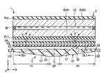
- FIG. 1 is a perspective view showing a schematic configuration of a display device 1 according to the first embodiment.
- the display device 1 can be used in various devices such as a smartphone, a tablet terminal, a mobile phone terminal, a personal computer, a television receiver, an in-vehicle device, a game machine, and a wearable terminal.
- the display device 1 includes a display panel 2, a lighting device 3 that is a backlight, a drive IC chip 4 (controller) that drives the display panel 2, and a flexible circuit board that transmits a control signal to the display panel 2 and the lighting device 3. It is provided with FPC1 and FPC2.
- the flexible circuit boards FPC1 and FPC2 are connected to a control module that controls the operations of the display panel 2 and the lighting device 3.
- the display panel 2 includes a first substrate SUB1 (array substrate) and a second substrate SUB2 (opposing substrate) facing the first substrate SUB1.
- the display panel 2 has a display area DA for displaying an image.
- the display panel 2 includes, for example, a plurality of pixels PX arranged in a matrix in the display area DA.
- the lighting device 3 includes a first light source LS1, a second light source LS2, and a light guide plate LG facing the first substrate SUB1.
- the first light source LS1 faces one side surface of the light guide plate LG
- the second light source LS2 faces the other side surface of the light guide plate LG.
- each of the light sources LS1 and LS2 is shown in FIG. 1 one by one, actually, a plurality of first light sources LS1 and a plurality of second light sources LS2 are provided (see FIG. 3).
- a first direction X, a second direction Y and a third direction Z are defined.
- the respective directions X, Y, Z are, for example, orthogonal to each other.
- viewing the display device 1 from a direction parallel to the third direction Z is referred to as a plan view.
- seeing a cross section of the display device 1 parallel to the XZ plane is referred to as a cross sectional view.
- each of the substrates SUB1 and SUB2 and the light guide plate LG has long sides along the first direction X and short sides along the second direction Y, and has a rectangular shape in plan view. ..
- the shape of each of the substrates SUB1 and SUB2 and the light guide plate LG is not limited to this, and the shape in plan view may be another shape such as a square or a circle.
- FIG. 2 is a schematic sectional view of the display device 1 parallel to the XZ plane.
- the display panel 2 further includes a seal material SL, a liquid crystal layer LC, a first polarizing plate PL1, and a second polarizing plate PL2.
- the substrates SUB1 and SUB2 are attached to each other with a sealing material SL.
- the liquid crystal layer LC is enclosed between the seal material SL and the substrates SUB1 and SUB2.
- the first polarizing plate PL1 is attached to the lower surface (the surface facing the light guide plate LG) of the first substrate SUB1.
- the second polarizing plate PL2 is attached to the upper surface of the second substrate SUB2 (the surface not facing the first substrate SUB1).
- the polarization axes of the polarizing plates PL1 and PL2 are, for example, orthogonal to each other.
- the light guide plate LG has a first surface 51, a second surface 52 opposite to the first surface 51, a first end portion 53, and a second end portion 54 opposite to the first end portion 53. ing.
- the display panel 2 faces the second surface 52.
- the first light source LS1 faces the first end portion 53
- the second light source LS2 faces the second end portion 54.
- an optical element such as a lens for adjusting the width or angle of the light from each of the light sources LS1 and LS2 is provided. It may be further arranged.
- the light guide plate LG includes a central portion CP located between the first end portion 53 and the second end portion 54 in the first direction X, and a first portion P1 located between the first end portion 53 and the central portion CP. , And a second portion P2 located between the second end portion 54 and the central portion CP.
- the central portion CP includes the center C of the light guide plate LG in the first direction X.
- the first portion P1 has a shape in which the thickness increases from the first end portion 53 toward the central portion CP.
- the second portion P2 has a shape in which the thickness increases from the second end portion 54 toward the central portion CP.
- the second surface 52 is a flat surface. Therefore, the change in the thickness of the light guide plate LG is caused by the change in the shape of the first surface 51.
- the light guide plate LG has a plane-symmetrical shape with respect to a YZ plane including the center C, for example. In the example of FIG.
- the first surface 51 and the second surface 52 are parallel to each other in the central portion CP, but actually the first surface 51 has a shape as shown in FIG. 8 described later. Further, the second surface 52 is provided with a reflecting structure for reflecting the light from each of the light sources LS1 and LS2.
- the first light source LS1 irradiates the first end portion 53 with diffused light having a spread centered on the first irradiation direction DL1.
- the second light source LS2 irradiates the second end portion 54 with diffused light having a spread centered on the second irradiation direction DL2.
- the irradiation directions DL1 and DL2 are, for example, opposite directions and are parallel to the first direction X.
- a laser light source such as a semiconductor laser that emits polarized laser light can be used as a laser light source.
- Each of the light sources LS1 and LS2 may include a plurality of light emitting elements that emit light of different colors. For example, if each of the light sources LS1 and LS2 includes three light emitting elements that emit red, green, and blue light, respectively, it is possible to obtain light of a mixed color (for example, white) of these colors.
- a mixed color for example, white
- the display device 1 includes a prism sheet PS between the display panel 2 and the light guide plate LG. Further, the display device 1 includes a diffusion sheet DS (diffusion layer) between the prism sheet PS and the display panel 2.
- the prism sheet PS includes a large number of prisms Pa extending parallel to the second direction Y. These prisms Pa are formed, for example, on the lower surface of the prism sheet PS (the surface facing the light guide plate LG) and protrude toward the light guide plate LG. However, these prisms Pa may be formed on the upper surface (the surface facing the display panel 2) of the prism sheet PS.
- FIG. 2 an example of the optical path of the light L1 emitted by the first light source LS1 is shown by a solid line, and an example of the optical path of the light L2 emitted by the second light source LS2 is shown by a broken line.
- the light L1 emitted from the first light source LS1 enters the light guide plate LG from the first end portion 53, propagates through the light guide plate LG while being reflected by the surfaces 51 and 52, and eventually deviates from the total reflection condition of the second surface 52. And is emitted from the second surface 52.
- the light L2 emitted from the second light source LS2 enters the light guide plate LG from the second end portion 54, propagates through the light guide plate LG while being reflected by the surfaces 51 and 52, and eventually deviates from the total reflection condition of the second surface 52. And is emitted from the second surface 52.
- the second surface 52 corresponds to the emission surface from which light is emitted.
- the display panel 2 displays an image using the light emitted from the second surface 52.
- the prism sheet PS converts light emitted from the second surface 52 into light substantially parallel to the third direction Z.
- the “light substantially parallel to the third direction Z” is not only light that is strictly parallel to the third direction Z, but also has an inclination with respect to the third direction Z when compared with when it is emitted from the second surface 52. And includes light that has been converted sufficiently small by the prism sheet PS.
- the prism Pa is preferably formed on the lower surface of the prism sheet PS.
- the light that has passed through the prism sheet PS is diffused by the diffusion sheet DS and applied to the display panel 2. Even if the viewing angle of light that has passed through the prism sheet PS is narrow, the viewing angle can be widened by diffusing this light with the diffusion sheet DS.
- the first polarizing plate PL1 may be omitted.
- the so-called transparent liquid crystal display device in which the background of the display device 1 can be seen through can be obtained by increasing the translucency of each of the substrates SUB1 and SUB2.
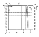
- FIG. 3 is a schematic plan view of the lighting device 3.
- eight first light sources LS1 are arranged along the first end portion 53 and eight second light sources LS2 are arranged along the second end portion 54, but the light sources LS1 and LS2 are arranged. Is not limited to this.
- the intensity of the light emitted from the first light source LS1 is the highest on the first optical axis AX1, and the intensity of the light emitted from the second light source LS2 is the highest on the second optical axis AX2.
- the light sources LS1 and LS2 are arranged in a staggered manner in the second direction Y, as shown in the figure. That is, the first optical axis AX1 of the light emitted from the first light source LS1 in the first irradiation direction DL1 and the second optical axis AX2 of the light emitted from the second light source LS2 in the second irradiation direction DL2 are in the second direction Y. They are offset from each other.
- the first optical axis AX1 and the second optical axis AX2 may be aligned in the second direction Y.
- FIG. 4 is a plan view for explaining the relationship between the light emitted by the first light source LS1 and the brightness of the second surface 52.
- the light emitted by the first light source LS1 is laser light, and therefore has excellent directivity and convergence. Therefore, when viewed in the XY plane, the spread in the second direction Y is smaller than that of a general LED. Therefore, in the first portion P1, there is a region NA through which the light from the first light source LS1 does not pass. On the other hand, in the central portion CP and the second portion P2, the light passes through the entire area.
- the light from the first light source LS1 is less likely to deviate from the total reflection condition of the second surface 52 in the first portion P1, and does not go out much from the second surface 52.
- this light is likely to deviate from the total reflection condition of the second surface 52 in the second portion P2, and a large amount of this light is emitted from the second surface 52. Further, this light is emitted from the second surface 52 with lower brightness in the central portion CP than in the second portion P2.
- the light from the second light source LS2 does not emit much from the second surface 52 in the second portion P2, and emits much from the second surface 52 in the first portion P1.
- the first light source LS1 mainly plays a role of lighting the second surface 52 of the second portion P2
- the second light source LS2 mainly plays a role of lighting the second surface 52 of the first portion P1.
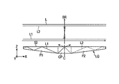
- 5 and 6 are graphs showing an example of the brightness (BR) of the light emitted from the second surface 52.
- the light L1 from the first light source LS1 has extremely low brightness.
- the brightness of the light L1 sharply increases in the vicinity of the center C and becomes high in the second portion P2.
- the light L2 from the second light source LS2 has low brightness in the second portion P2, sharply rises in the vicinity of the center C, and has high brightness in the first portion P1.
- the light L2 from the second light source LS2 is emitted from the second surface 52 with higher brightness than the light L1 from the first light source LS1.
- the light L1 from the first light source LS1 is emitted from the second surface 52 with higher brightness than the light L2 from the second light source LS2.
- the brightness of the combined light L of the lights L1 and L2 is constant throughout the first portion P1, the second portion P2, and the central portion CP, as shown in FIG.
- the brightness changes of the lights L1 and L2 do not match in the central portion CP
- the brightness of the combined light L becomes nonuniform in the central portion CP.
- FIG. 6 shows an example in which both the lights L1 and L2 are insufficient at the center C, and the brightness of the combined light L sharply decreases at the center C and in the vicinity thereof.
- the overlap of the brightness of the lights L1 and L2 is too large at the center C, the brightness of the combined light L sharply increases at the center C and in the vicinity thereof.
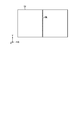
- FIG. 7 is a plan view of the second surface 52 schematically showing the luminance distribution of the combined light shown in FIG. Since the brightness is lowered at the center C, a dark line DL along the center C is generated on the second surface 52. When the brightness of the combined light L sharply rises in and around the center C, a bright line is generated instead of the dark line DL.
- the light guide plate LG has a configuration capable of suppressing such dark lines and bright lines. Hereinafter, details of the light guide plate LG will be described.
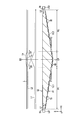
- FIG. 8 is a schematic sectional view of the light guide plate LG in the present embodiment.
- the first surface 51 of the light guide plate LG has a first reflection structure 60 provided in the central portion CP, a second reflection structure 70 provided in the first portion P1, and a third reflection structure provided in the second portion P2.
- Structure 80 Each of the reflecting structures 60, 70, 80 is, for example, a prism protruding downward (a direction opposite to the third direction Z).
- a straight line connecting the vertices of the second reflecting structure 70 is defined as a first virtual line VL1, and a straight line connecting the vertices of the third reflecting structure 80 is defined as a second virtual line VL2.
- the first virtual line VL1 is inclined at an angle ⁇ 1 with respect to the second surface 52.
- the second virtual line VL2 is inclined at an angle ⁇ 2 with respect to the second surface 52.
- the angles ⁇ 1 and ⁇ 2 are both acute angles. From the viewpoint of making the luminance distribution of the second surface 52 uniform, it is preferable that the angles ⁇ 1 and ⁇ 2 are the same. However, the angles ⁇ 1 and ⁇ 2 may be different.
- Each first reflection structure 60 in the central portion CP is located, for example, on the second surface 52 side with respect to each virtual line VL1, VL2.
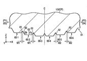
- FIG. 9 is a cross-sectional view of the central portion CP in which the plurality of first reflecting structures 60 are enlarged.
- first reflecting structures 60-1 to 60-6 are shown arranged in order from the first portion P1 (left side in the figure) to the second portion P2 (right side in the figure), but the central portion is shown.
- the number of the first reflective structures 60 arranged in the CP is not limited to this.
- each first reflecting structure 60 has the illustrated cross-sectional shape and extends in the second direction Y.
- the first reflective structure 60 has a first reflective surface 61 and a second reflective surface 62.
- the first reflecting surface 61 is a plane facing the first end portion 53 on the left side of the cross section of FIG. 9, and reflects the light from the first light source LS1 toward the second surface 52.
- the second reflecting surface 62 is a flat surface facing the second end portion 54 on the right side of the cross section of FIG. 9, and reflects the light from the second light source LS2 toward the second surface 52.
- the first reflecting surface 61 faces the first end portion 53
- the distance between the end portion of the first reflecting surface 61 on the second end portion 54 side and the second surface 52 is the first end.
- the first reflecting surface 61 is inclined with respect to the XY plane so as to be smaller than the distance between the end of the first reflecting surface 61 on the portion 53 side and the second surface 52.
- the fourth reflecting surface 81 described later means that the second reflecting surface 62 faces the second end portion 54” means that the distance between the end portion of the second reflecting surface 62 on the first end portion 53 side and the second surface 52 is the second end portion.
- the second reflecting surface 62 is inclined with respect to the XY plane so as to be smaller than the distance between the end of the second reflecting surface 62 on the 54 side and the second surface 52.
- the first reflective structure 60 is arranged between the first reflective surface 61 and the adjacent first reflective surface 61, or between the second reflective surface 62 and the adjacent second reflective surface 62.
- the first reflective structure 60 has a shape such that the flat surface 63 is the top surface.
- the flat surface 63 is, for example, parallel to the second surface 52, and reflects the light from each of the light sources LS1 and LS2 at a shallow angle that is totally reflected by the second surface 52.
- the light from the first light source LS1 propagates well beyond the central portion CP to the second portion P2.
- the light from the second light source LS2 propagates well beyond the central portion CP to the first portion P1.
- the first reflecting surface 61 is inclined with respect to the flat surface 63 (or the second surface 52) at an angle ⁇ a which is an obtuse angle.
- the second reflecting surface 62 is inclined with respect to the flat surface 63 (or the second surface 52) at an angle ⁇ b which is an obtuse angle.
- these angles ⁇ a and ⁇ b are equal to each other.
- the angle of the light from the first light source LS1 which is reflected by the first reflecting surface 61 is emitted from the second surface 52, and reaches the prism sheet PS, and the angle of the light from the second reflecting surface 62 is reflected by the second surface 52.
- the angle of the light emitted from the second light source LS2 that reaches the prism sheet PS is substantially equal.
- the light from each of the light sources LS1 and LS2 is supplied to the display panel PNL under the same condition, so that the uneven brightness in the image can be suppressed.
- the first reflecting surface 61 is tilted at the angle ⁇ a and the second reflecting surface 62 is tilted at the angle ⁇ b. Further, the widths of the flat surfaces 63 of the first reflecting structures 60-1 to 60-6 in the first direction X are the same.
- the width W1 of the first reflecting surface 61 in the first direction X and the width W2 of the second reflecting surface 62 in the first direction X are different in each of the reflecting structures 60-1 to 60-6. That is, the first reflection surface 61 closer to the first portion P1 has a smaller width W1, and the first reflection surface 61 closer to the second portion P2 has a larger width W1. On the contrary, the second reflection surface 62 closer to the second portion P2 has a smaller width W2, and the second reflection surface 62 closer to the first portion P1 has a larger width W2.
- the areas of the plurality of first reflecting surfaces 61 increase as approaching from the first portion P1 to the second portion P2.
- the areas of the plurality of second reflecting surfaces 62 increase as the area approaches the first portion P1 from the second portion P2.
- the density of the plurality of first reflecting surfaces 61 on the first surface 51 is different from that of the first portion P1. It increases as it approaches the second portion P2. On the contrary, the densities of the plurality of second reflecting surfaces 62 on the first surface 51 increase from the second portion P2 toward the first portion P1.
- the area of the first reflecting surface 61 in the first reflecting structure 60 is the area of the second reflecting surface 62. Smaller than.
- the area of the second reflecting surface 62 in the first reflecting structure 60 is smaller than the area of the first reflecting surface 61.
- FIG. 10 is a sectional view of the first portion P1 in which the plurality of second reflective structures 70 are enlarged.
- two second reflective structures 70-1 and 70-2 arranged in the first direction X are shown.
- each second reflective structure 70 has the illustrated cross-sectional shape and extends in the second direction Y.
- the second reflective structure 70 has a third reflective surface 71 and a flat surface 72.
- the third reflection surface 71 is a flat surface facing the second end portion 54 on the right side of the cross section of FIG. 10, and reflects the light from the second light source LS2 toward the second surface 52.
- the flat surface 72 is, for example, parallel to the second surface 52, and reflects the light from each of the light sources LS1 and LS2 at a shallow angle that is totally reflected by the second surface 52.
- the second reflective structure 70 does not have a reflective surface that faces the first end portion 53.
- the third reflecting surface 71 is inclined with respect to the flat surface 72 (or the second surface 52) at an angle ⁇ c which is an obtuse angle.
- the width W3 of the third reflecting surface 71 in the first direction X may be different in each reflecting structure 70.
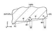
- FIG. 11 is a cross-sectional view of the second portion P2 in which the plurality of third reflecting structures 80 are enlarged.
- the plurality of third reflecting structures 80 are enlarged.
- two third reflective structures 80-1 and 80-2 arranged in the first direction X are shown.
- each third reflection structure 80 has the illustrated cross-sectional shape at any position in the second direction Y.
- the third reflective structure 80 has a fourth reflective surface 81 and a flat surface 82.
- the fourth reflecting surface 81 is a plane facing the first end portion 53 on the left side of the cross section of FIG. 11, and reflects the light from the first light source LS1 toward the second surface 52.
- the flat surface 82 is, for example, parallel to the second surface 52, and reflects the light from each of the light sources LS1 and LS2 at a shallow angle that is totally reflected by the second surface 52.
- the third reflective structure 80 does not have a reflective surface facing the second end 54.
- the cross-sectional shape of the second portion P2 shown in FIG. 11 corresponds to the left-right inverted cross-sectional shape of the first portion P1 shown in FIG. Therefore, the description of the conditions applicable to the angle ⁇ d formed by the fourth reflecting surface 81 and the flat surface 82 and the width W4 of the fourth reflecting surface 81 is omitted.
- a plurality of first reflecting surfaces 61 are provided in the central portion CP, and the area of these first reflecting surfaces 61 increases as they approach the second portion P2. Therefore, the brightness of the light L1 reflected by the first reflecting surface 61 and emitted from the second surface 52 does not change steeply as shown in FIG. 5, but gradually increases from the left end to the right end of the central portion CP in the drawing. Rise.
- the plurality of second reflecting surfaces 62 are provided in the central portion CP, and the area of these second reflecting surfaces 62 increases as the area approaches the first portion P1. Therefore, the brightness of the light L2 reflected by the second reflecting surface 62 and emitted from the second surface 52 also gradually increases from the right end to the left end in the figure of the central portion CP.
- the brightness when the light L1 from the first light source LS1 is emitted from the second surface 52 from the first end portion 53 side toward the second end portion 54 side is sequentially. It has a brightness gradient characteristic that becomes higher and the brightness when the light L2 from the second light source LS2 is emitted from the second surface 52 from the second end portion 54 side toward the first end portion 53 side becomes sequentially higher.
- the light emitted by the first light source LS1 is a laser light, an area NA in which the light does not pass occurs in the first portion P1 as shown in FIG. If the light from the first light source LS1 is emitted in the first portion P1, luminance unevenness corresponding to the area NA occurs.
- the first surface 51 does not have a reflecting surface that faces the first end portion 53. Therefore, in the first portion P1, the light from the first light source LS1 does not radiate much from the second surface 52, so that the uneven brightness is suppressed.
- the first surface 51 does not have a reflective surface that faces the second end portion 54 in the second portion P2. Therefore, uneven brightness in the second portion P2 due to the light from the second light source LS2 is suppressed.
- the display quality of the display device 1 can be improved by using the lighting device 3 that can realize such a favorable luminance distribution.
- various suitable effects can be obtained from this embodiment.
- FIG. 12 is a sectional view of the central portion CP in the second embodiment.
- the first reflecting structure 60 has a shape protruding downward so that the flat surface 63 is the top surface.
- the first reflecting structure 60 in the example of FIG. 12 has a shape recessed upward (in the direction toward the second surface 52) so that the flat surface 63 serves as the bottom surface.
- the same effect as the first embodiment can be obtained.
- the shape of the first surface 51 in the central portion CP can be modified in various ways.
- the lighting device 3 may include a reflecting member that returns the light leaking from the first surface 51 to the light guide plate LG.
- FIG. 13 is sectional drawing which shows an example of the illuminating device 3 provided with the reflection member.
- the lighting device 3 includes a flat plate-shaped reflecting member 90 facing the first surface 51.
- the reflecting member 90 for example, a sheet material made of a metal material can be used.
- FIG. 14 is a cross-sectional view showing another example of the lighting device 3 including the reflecting member 90.
- the reflecting member 90 has a first region 91 and a second region 92.
- the first region 91 is parallel to the first surface 51 of the first portion P1.
- the second region 92 is parallel to the first surface 51 of the second portion P2.
- the first region 91 faces the left half of the first portion P1 and the central portion CP.
- the second area 92 faces the right half of the second portion P2 and the central portion CP.
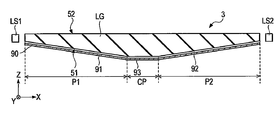
- FIG. 15 is a cross-sectional view showing still another example of the lighting device 3 including the reflection member 90.
- the reflection member 90 has a first region 91, a second region 92, and a third region 93.
- the third region 93 is parallel to the first surface 51 in the central portion CP.
- the first region 91, the second region 92, and the third region 93 face the first portion P1, the second portion P2, and the central portion CP, respectively.
- the third region 93 may be a curved surface along the first surface 51.
- the reflection member As described above, it is possible to effectively utilize the light leaking from the first surface 51 and increase the brightness of the second surface 52. As a result, power saving of the lighting device 3 and improvement of the image quality of the display device 1 can be expected.
- FIG. 16 is a schematic cross-sectional view of the lighting device 3 according to the fourth embodiment.
- the lighting device 3 includes a light guide plate LG, a first light source LS1, and a reflecting member 90.
- the first end portion 53 includes an incident surface 53a and a side surface 53b.
- the configurations of the above-described embodiments can be applied to the light guide plate LG and the reflection member 90.
- the incident surface 53a is inclined at an angle ⁇ in with respect to the second surface 52.
- the angle ⁇ in is an acute angle larger than the first angle ⁇ 1 described above ( ⁇ 1 ⁇ in ⁇ 90°).
- the side surface 53b is, for example, a plane parallel to the YZ plane.
- the incident surface 53a is a flat surface in the example of FIG. 16, the incident surface 53a may be a curved surface. Further, the first end portion 53 does not have to have the side surface 53b.
- the first irradiation direction DL1 which is the direction in which the first light source LS1 emits light, is inclined with respect to the second main surface 52. That is, in the present embodiment, the first irradiation direction DL1 does not match the first direction X in a cross-sectional view. However, in the plan view, the first irradiation direction DL1 and the first direction X coincide with each other.
- the first light source LS1 overlaps the light guide plate LG in the thickness direction of the light guide plate LG (third direction Z). In the example of FIG. 16, all the first light sources LS1 overlap the light guide plate LG, but a part of the first light source LS1 may overlap the light guide plate LG.
- the same effect as that of each of the above-described embodiments can be obtained. Further, by disposing the first light source LS1 in the space below the light guide plate LG, it is possible to reduce the size of the illumination device 3 or the display device 1 and the size of the frame region.
- the same configurations as the first end portion 53 and the first light source LS1 disclosed in the present embodiment can be applied to the second end portion 54 and the second light source LS2.
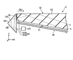
- FIG. 17 is a schematic sectional view of the lighting device 3 according to the fifth embodiment.
- the lighting device 3 includes a light guide plate LG, a first light source LS1, and a reflecting member 90.
- the configurations of the above-described embodiments can be applied to the light guide plate LG and the reflection member 90.
- the first light source LS1 overlaps the light guide plate LG in the thickness direction of the light guide plate LG (third direction Z). In the example of FIG. 17, all the first light sources LS1 overlap the light guide plate LG, but a part of the first light source LS1 may overlap the light guide plate LG.
- the lighting device 3 includes the bent body 100 arranged near the first end portion 53.
- the bent body 100 shown in FIG. 17 is a prism having a triangular shape in the XZ cross section and extending in the second direction Y.
- the bent body 100 has a first surface 101, a second surface 102, and a third surface 103.
- one bent body 100 may be provided for each of the plurality of first light sources LS1 arranged in the second direction Y as shown in FIG. Further, one bent body 100 may be provided for each of the two or more first light sources LS1, or one bent body 100 may be provided for all the first light sources LS1.
- the first surface 101 has an entrance area 101a and an exit area 101b.
- the incident area 101a faces the first light source LS1.
- the emission area 101b faces the first end portion 53 of the light guide plate LG.
- the first surface 101 is parallel to the third direction Z, but the first surface 101 may be tilted with respect to the third direction Z.
- the second surface 102 and the third surface 103 are inclined at a predetermined angle with respect to the first surface 101.
- the light emitted from the first light source LS1 enters the bent body 100 from the incident area 101a.
- the incident light is reflected by the second surface 102, further reflected by the third surface 103, and emitted from the emission area 101b.
- the emitted light is applied to the first end portion 53 of the light guide plate LG along the first irradiation direction DL1 and propagates through the light guide plate LG while being reflected by the surfaces 51 and 52 of the light guide plate LG.
- the optical path of the light emitted from the first light source LS1 is bent in the first irradiation direction DL1 by the bending body 100 and is incident on the light guide plate LG.
- the degree of freedom in the arrangement position of the first light source LS1 is increased. Therefore, by arranging the first light source LS1 in the space below the light guide plate LG as shown in FIG. 17, for example, the illumination device 3 or the display device 1 can be downsized and the frame region can be narrowed.
- FIG. 17 shows an example in which the bent body 100 is a prism
- the bent body 100 may be a reflecting member (mirror member) having a shape corresponding to the second surface 102 and the third surface 103.
- the bent body 100 may have a structure in which the light from the first light source LS1 is reflected only once to irradiate the first end portion 53, or may be reflected three times or more to irradiate the first end portion 53. It may have a structure.
- the configuration described near the first light source LS1 in the present embodiment can be similarly applied to the second light source LS2 side.
Landscapes
- Engineering & Computer Science (AREA)
- General Engineering & Computer Science (AREA)
- Planar Illumination Modules (AREA)
- Liquid Crystal (AREA)
Abstract
一実施形態に係る照明装置は、レーザー光を発する第1及び第2光源と、これら光源からの光がそれぞれ照射される第1及び第2端部、入射した光を反射する第1面および当該光が出射する第2面を有する導光板とを備える。導光板は、中央部分と、第2光源からの光が高輝度で第2面から出射する第1部分と、第1光源からの光が高輝度で第2面から出射する第2部分とを有する。中央部分は、第1端部側から第2端部側に向かって第1光源からの光が第2面から出射する際の輝度が順次高くなり、且つ第2端部側から第1端部側に向かって第2光源からの光が第2面から出射する際の輝度が順次高くなる輝度傾斜特性を有する。
Description
本発明の実施形態は、照明装置および表示装置に関する。
例えば、液晶表示装置などの表示装置は、画素を有する表示パネルと、表示パネルを照明するバックライトなどの照明装置とを備えている。照明装置は、光を発する光源と、この光源からの光が照射される導光板とを備えている。光源からの光は、導光板の端部から導光板内に入り、導光板内を伝播し、導光板の一方の主面に相当する出射面から出射する。例えば特許文献1に開示されたように、導光板の両端部の近傍にそれぞれ光源を配置した照明装置も知られている。
また、例えば特許文献2に開示されたように、導光板の両端部の近傍にそれぞれレーザー光を放つ光源を配置した照明装置が提案されている。このような構成においては、一方の光源からの光が、他方の光源に近い導光板の領域から主に出射する。
上述のようにレーザー光を放つ光源を用いた照明装置においては、光源に近い側の領域と遠い側の領域とで、当該光源からの光が導光板から出射する輝度が大きく異なる。したがって、一方の光源からの光が強く出射する領域と、他方の光源からの光が強く出射する領域との位置関係がずれると、導光板の中央部分に暗線や明線が生じ得る。
本発明は、導光板の出射面から良好な輝度分布の光を照射することが可能な照明装置および当該照明装置を備える表示装置を提供することを目的の一つとする。
一実施形態に係る照明装置は、レーザー光を発する第1光源および第2光源と、前記第1光源からの光が照射される第1端部、前記第2光源からの光が照射される第2端部、前記第1端部および前記第2端部から入射した光を反射する第1面、および、前記第1面で反射された光が出射する第2面を有する導光板と、を備えている。前記導光板は、前記第1端部と前記第2端部の間に位置する中央部分と、前記第1端部と前記中央部分の間に位置し、前記第2光源からの光が前記第1光源からの光よりも高輝度で前記第2面から出射する第1部分と、前記第2端部と前記中央部分の間に位置し、前記第1光源からの光が前記第2光源からの光よりも高輝度で前記第2面から出射する第2部分と、を有している。前記中央部分は、前記第1端部側から前記第2端部側に向かって前記第1光源からの光が前記第2面から出射する際の輝度が順次高くなり、且つ前記第2端部側から前記第1端部側に向かって前記第2光源からの光が前記第2面から出射する際の輝度が順次高くなる輝度傾斜特性を有する。
一実施形態に係る表示装置は、前記照明装置と、前記第2面に対向し、前記第2面から出射する光を用いて画像を表示する表示パネルと、を備えている。
いくつかの実施形態につき、図面を参照しながら説明する。
なお、開示はあくまで一例に過ぎず、当業者において、発明の主旨を保っての適宜変更について容易に想到し得るものについては、当然に本発明の範囲に含有される。また、図面は、説明をより明確にするため、実際の態様に比べて模式的に表される場合があるが、あくまで一例であって、本発明の解釈を限定するものではない。各図において、連続して配置される同一または類似の要素については符号を省略することがある。また、本明細書と各図において、既出の図に関して前述したものと同一または類似した機能を発揮する構成要素には同一の参照符号を付し、重複する詳細な説明を省略することがある。
なお、開示はあくまで一例に過ぎず、当業者において、発明の主旨を保っての適宜変更について容易に想到し得るものについては、当然に本発明の範囲に含有される。また、図面は、説明をより明確にするため、実際の態様に比べて模式的に表される場合があるが、あくまで一例であって、本発明の解釈を限定するものではない。各図において、連続して配置される同一または類似の要素については符号を省略することがある。また、本明細書と各図において、既出の図に関して前述したものと同一または類似した機能を発揮する構成要素には同一の参照符号を付し、重複する詳細な説明を省略することがある。
各実施形態においては、表示装置の一例として、透過型の液晶表示装置を開示する。また、照明装置の一例として、液晶表示装置のバックライトを開示する。ただし、各実施形態は、他種の表示装置や照明装置に対する、各実施形態にて開示される個々の技術的思想の適用を妨げるものではない。他種の表示装置としては、例えば、透過型の機能に加えて外光を反射してこの反射光を表示に利用する反射型の機能を備えた液晶表示装置や、Micro Electro Mechanical System(MEMS)シャッターが光学素子として機能する機械式表示パネルを有する表示装置などが想定される。他種の照明装置としては、例えば、表示装置の前面に配置されるフロントライトなどが想定される。また、照明装置は、表示装置の照明とは異なる用途で使用されるものであってもよい。
[第1実施形態]
図1は、第1実施形態に係る表示装置1の概略的な構成を示す斜視図である。表示装置1は、例えば、スマートフォン、タブレット端末、携帯電話端末、パーソナルコンピュータ、テレビ受像装置、車載装置、ゲーム機器、ウェアラブル端末等の種々の装置に用いることができる。
図1は、第1実施形態に係る表示装置1の概略的な構成を示す斜視図である。表示装置1は、例えば、スマートフォン、タブレット端末、携帯電話端末、パーソナルコンピュータ、テレビ受像装置、車載装置、ゲーム機器、ウェアラブル端末等の種々の装置に用いることができる。
表示装置1は、表示パネル2と、バックライトである照明装置3と、表示パネル2を駆動する駆動ICチップ4(コントローラ)と、表示パネル2および照明装置3へ制御信号を伝達するフレキシブル回路基板FPC1,FPC2とを備えている。例えば、フレキシブル回路基板FPC1,FPC2は、表示パネル2および照明装置3の動作を制御する制御モジュールに接続されている。
表示パネル2は、第1基板SUB1(アレイ基板)と、第1基板SUB1に対向する第2基板SUB2(対向基板)とを備えている。表示パネル2は、画像を表示する表示領域DAを有している。表示パネル2は、例えば、表示領域DAにおいてマトリクス状に配列された複数の画素PXを備えている。
照明装置3は、第1光源LS1と、第2光源LS2と、第1基板SUB1に対向する導光板LGとを備えている。第1光源LS1は導光板LGの一方の側面に対向し、第2光源LS2は導光板LGの他方の側面に対向している。図1においては各光源LS1,LS2を1つずつ示しているが、実際には複数の第1光源LS1と複数の第2光源LS2とが設けられている(図3参照)。
図1に示すように、第1方向X、第2方向Yおよび第3方向Zを定義する。各方向X,Y,Zは、例えば互いに直交する。本開示においては、表示装置1を第3方向Zと平行な方向から見ることを平面視と呼ぶ。また、X-Z平面と平行な表示装置1の断面を見ることを断面視と呼ぶ。図1の例において、各基板SUB1,SUB2および導光板LGは、第1方向Xに沿う長辺と、第2方向Yに沿う短辺とを有しており、平面視における形状が長方形である。但し、各基板SUB1,SUB2および導光板LGの形状はこれに限定されず、平面視における形状が正方形や円形など他の形状であってもよい。
図2は、X-Z平面と平行な表示装置1の概略的な断面図である。表示パネル2は、シール材SLと、液晶層LCと、第1偏光板PL1と、第2偏光板PL2とをさらに備えている。各基板SUB1,SUB2は、シール材SLにより貼り合わされている。液晶層LCは、シール材SLおよび各基板SUB1,SUB2の間に封入されている。
第1偏光板PL1は、第1基板SUB1の下面(導光板LGと対向する面)に貼付されている。第2偏光板PL2は、第2基板SUB2の上面(第1基板SUB1と対向しない面)に貼付されている。各偏光板PL1,PL2の偏光軸は、例えば互いに直交する。
導光板LGは、第1面51と、第1面51の反対側の第2面52と、第1端部53と、第1端部53の反対側の第2端部54とを有している。表示パネル2は、第2面52と対向している。第1光源LS1は第1端部53に対向し、第2光源LS2は第2端部54に対向している。第1光源LS1と第1端部53の間や第2光源LS2と第2端部54の間に、各光源LS1,LS2からの光の幅や角度を調整するためのレンズなどの光学素子がさらに配置されてもよい。
導光板LGは、第1方向Xにおいて第1端部53と第2端部54の間に位置する中央部分CPと、第1端部53と中央部分CPの間に位置する第1部分P1と、第2端部54と中央部分CPの間に位置する第2部分P2とを有している。
中央部分CPは、導光板LGの第1方向Xにおける中心Cを含む。第1部分P1は、第1端部53から中央部分CPに向けて厚さが増す形状を有する。第2部分P2は、第2端部54から中央部分CPに向けて厚さが増す形状を有する。図2の例においては、第2面52が平面である。したがって、導光板LGの厚さの変化は、第1面51の形状変化に起因する。導光板LGは、例えば中心Cを含むY-Z平面に関して面対称の形状である。図2の例では、中央部分CPにおいて第1面51と第2面52が平行であるが、実際には第1面51が後述の図8に示すような形状を有している。また、第2面52には、各光源LS1,LS2からの光を反射するための反射構造が設けられている。
第1光源LS1は、第1照射方向DL1を中心とした広がりを持つ拡散光を第1端部53に照射する。第2光源LS2は、第2照射方向DL2を中心とした広がりを持つ拡散光を第2端部54に照射する。各照射方向DL1,DL2は、例えば反対の方向であり、第1方向Xと平行である。各光源LS1,LS2の発光素子としては、例えば偏光したレーザー光を放つ半導体レーザーなどのレーザー光源を用いることができる。
各光源LS1,LS2は、それぞれ異なる色の光を発する複数の発光素子を備えてもよい。例えば、各光源LS1,LS2が赤色、緑色、青色の光を発する3つの発光素子をそれぞれ備えれば、これらの色の混合色(例えば白色)の光を得ることができる。
表示装置1は、表示パネル2と導光板LGの間に、プリズムシートPSを備えている。さらに、表示装置1は、プリズムシートPSと表示パネル2の間に、拡散シートDS(拡散層)を備えている。例えば、プリズムシートPSは、第2方向Yと平行に延びる多数のプリズムPaを備えている。これらのプリズムPaは、例えばプリズムシートPSの下面(導光板LGと対向する面)に形成され、導光板LGに向けて突出している。但し、これらのプリズムPaは、プリズムシートPSの上面(表示パネル2と対向する面)に形成されてもよい。
図2においては、第1光源LS1が発する光L1の光路の一例を実線で示し、第2光源LS2が発する光L2の光路の一例を破線で示している。第1光源LS1が発した光L1は、第1端部53から導光板LGに入り、各面51,52で反射しながら導光板LGを伝播し、やがて第2面52の全反射条件を外れて第2面52から出射する。第2光源LS2が発した光L2は、第2端部54から導光板LGに入り、各面51,52で反射しながら導光板LGを伝播し、やがて第2面52の全反射条件を外れて第2面52から出射する。このように、第2面52は、光が出射する出射面に相当する。表示パネル2は、第2面52から出射する光を用いて画像を表示する。
プリズムシートPSは、第2面52から出射した光を第3方向Zに実質的に平行な光に変換する。ここで、「第3方向Zに実質的に平行な光」は、第3方向Zと厳密に平行な光のみならず、第3方向Zに対する傾きが、第2面52から出射した際に比べて、プリズムシートPSにより十分に小さく変換された光を含む。各光源LS1,LS2からの光の偏光を維持する観点から、プリズムPaがプリズムシートPSの下面に形成されていることが好ましい。プリズムシートPSを経た光は、拡散シートDSで拡散されて、表示パネル2に照射される。プリズムシートPSを通過した光の視野角が狭い場合であっても、この光を拡散シートDSで拡散することにより視野角を広げることができる。
なお、各光源LS1,LS2からの光が十分に偏光された状態で表示パネル2に到達する場合には、第1偏光板PL1を省略してもよい。第1偏光板PL1を省略した場合には、例えば各基板SUB1,SUB2の透光性を高めることで、表示装置1の背景が透けて見えるいわゆる透明液晶表示装置を得ることができる。
図3は、照明装置3の概略的な平面図である。この図の例においては、第1端部53に沿って8個の第1光源LS1が並び、第2端部54に沿って8個の第2光源LS2が並んでいるが、光源LS1,LS2の数はこれに限定されない。第1光源LS1が発する光の強度は第1光軸AX1において最も高く、第2光源LS2が発する光の強度は第2光軸AX2において最も高い。
各光源LS1,LS2は、図示したように、第2方向Yにおいて互い違いに配列されている。すなわち、第1光源LS1が第1照射方向DL1に発する光の第1光軸AX1と、第2光源LS2が第2照射方向DL2に発する光の第2光軸AX2とは、第2方向Yにおいて互いにずれている。なお、第1光軸AX1と第2光軸AX2が、第2方向Yにおいて揃っていてもよい。
図4は、第1光源LS1が放つ光と、第2面52の輝度との関係を説明するための平面図である。ここでは、3つの第1光源LS1と、これらが放つ光とを例示している。本実施形態において、第1光源LS1が放つ光はレーザー光であるため、指向性および収束性に優れている。したがって、X-Y平面で見たときには、第2方向Yへの広がりが一般的なLEDよりも小さい。そのため、第1部分P1においては、第1光源LS1からの光が通らない領域NAが存在する。一方で、中央部分CPおよび第2部分P2においては、当該光が全域を通る。
第1光源LS1からの光は、第1部分P1においては第2面52の全反射条件を外れにくく、第2面52からあまり出射しない。一方で、この光は、第2部分P2においては第2面52の全反射条件を外れやすく、第2面52から多く出射する。また、この光は、中央部分CPにおいては第2部分P2よりも低い輝度で第2面52から出射する。
なお、第2光源LS2からの光は、第2部分P2においては第2面52からあまり出射せず、第1部分P1においては第2面52から多く出射する。このように、第1光源LS1は主に第2部分P2における第2面52を点灯させる役割を担い、第2光源LS2は主に第1部分P1における第2面52を点灯させる役割を担う。
図5および図6は、第2面52から出射する光の輝度(BR)の一例を示すグラフである。第1部分P1において、第1光源LS1からの光L1は、極めて低輝度である。光L1の輝度は、中心Cの近傍において急峻に上昇し、第2部分P2においては高輝度となる。反対に、第2光源LS2からの光L2は、第2部分P2において低輝度であり、中心Cの近傍において急峻に上昇し、第1部分P1において高輝度となる。このように、第1部分P1においては、第2光源LS2からの光L2が第1光源LS1からの光L1よりも高輝度で第2面52から出射する。また、第2部分P2においては、第1光源LS1からの光L1が第2光源LS2からの光L2よりも高輝度で第2面52から出射する。
光L1,L2の合成光Lの輝度は、図5に示すように第1部分P1、第2部分P2および中央部分CPの全体にわたって一定であることが理想的である。しかしながら、中央部分CPにおいて光L1,L2それぞれの輝度変化が整合しない場合、合成光Lの輝度が中央部分CPにおいて不均一となる。図6においては、光L1,L2の双方が中心Cにおいて不足し、合成光Lの輝度が中心Cとその近傍において急峻に低下する例を示している。他の例として、光L1,L2の輝度の重なりが中心Cにおいて大き過ぎる場合には、合成光Lの輝度が中心Cとその近傍において急峻に上昇する。
図7は、図6に示す合成光の輝度分布を模式的に表す第2面52の平面図である。中心Cにおいて輝度が低下しているために、第2面52において中心Cに沿う暗線DLが生じる。合成光Lの輝度が中心Cとその近傍において急峻に上昇する場合には、この暗線DLに代えて明線が生じる。
これら暗線や明線により第2面52の輝度が不均一になると、表示パネルPNLの画質も低下し得る。本実施形態において、導光板LGは、このような暗線や明線を抑制することが可能な構成を備えている。以下、導光板LGの詳細について説明する。
図8は、本実施形態における導光板LGの概略的な断面図である。導光板LGの第1面51は、中央部分CPに設けられた第1反射構造60と、第1部分P1に設けられた第2反射構造70と、第2部分P2に設けられた第3反射構造80とを有している。各反射構造60,70,80は、例えば下方(第3方向Zの反対方向)に向けて突出したプリズムである。
第2反射構造70の頂点を繋ぐ直線を第1仮想線VL1と定義し、第3反射構造80の頂点を繋ぐ直線を第2仮想線VL2と定義する。第1仮想線VL1は、第2面52に対して角度θ1で傾いている。第2仮想線VL2は、第2面52に対して角度θ2で傾いている。角度θ1,θ2は、いずれも鋭角である。第2面52の輝度分布を均一化する観点からは、角度θ1,θ2が同じであることが好ましい。ただし、角度θ1,θ2が異なってもよい。中央部分CPの各第1反射構造60は、例えば各仮想線VL1,VL2よりも第2面52側に位置している。
図9は、複数の第1反射構造60を拡大した中央部分CPの断面図である。ここでは、第1部分P1(図中左方)から第2部分P2(図中右方)に向けて順に並ぶ6つの第1反射構造60-1~60-6を示しているが、中央部分CPに配置される第1反射構造60の数はこれに限定されない。例えば、各第1反射構造60は、図示した断面形状を有して第2方向Yに延在している。
第1反射構造60は、第1反射面61と、第2反射面62とを有している。第1反射面61は、図9の断面の左方にある第1端部53に対向する平面であり、第1光源LS1からの光を第2面52に向けて反射する。第2反射面62は、図9の断面の右方にある第2端部54に対向する平面であり、第2光源LS2からの光を第2面52に向けて反射する。
ここで、「第1反射面61が第1端部53に対向する」とは、第2端部54側の第1反射面61の端部と第2面52との距離が、第1端部53側の第1反射面61の端部と第2面52との距離よりも小さくなるように、第1反射面61がX-Y平面に対して傾斜していることを意味する。後述する第4反射面81についても同様である。また、「第2反射面62が第2端部54に対向する」とは、第1端部53側の第2反射面62の端部と第2面52との距離が、第2端部54側の第2反射面62の端部と第2面52との距離よりも小さくなるように、第2反射面62がX-Y平面に対して傾斜していることを意味する。後述する第3反射面71についても同様である。
図9の例において、第1反射構造60は、第1反射面61と隣接する第1反射面61との間、或いは、第2反射面62と隣接する第2反射面62との間に配置された平坦面63を有している。本実施形態いおいて、第1反射構造60は、平坦面63が頂面となるように突出した形状である。平坦面63は、例えば第2面52と平行であり、各光源LS1,LS2からの光を、第2面52で全反射される浅い角度で反射する。これにより、第1光源LS1からの光が中央部分CPを超えて第2部分P2まで良好に伝播する。同様に、第2光源LS2からの光が中央部分CPを超えて第1部分P1まで良好に伝播する。
第1反射面61は、平坦面63(または第2面52)に対して鈍角である角度θaで傾いている。第2反射面62は、平坦面63(または第2面52)に対して鈍角である角度θbで傾いている。例えば、これら角度θa,θbは互いに等しい。この場合、第1反射面61で反射されて第2面52から出射しプリズムシートPSに到達する第1光源LS1からの光の角度と、第2反射面62で反射されて第2面52から出射しプリズムシートPSに到達する第2光源LS2からの光の角度とが実質的に等しくなる。これにより、各光源LS1,LS2からの光が同等の条件で表示パネルPNLに供給されるので、画像における輝度むらを抑制できる。
図9の例においては、第1反射構造60-1~60-6のいずれにおいても、第1反射面61が角度θaで傾き、第2反射面62が角度θbで傾いている。また、第1反射構造60-1~60-6の平坦面63の第1方向Xにおける幅が同じである。
第1反射面61の第1方向Xにおける幅W1および第2反射面62の第1方向Xにおける幅W2は、各反射構造60-1~60-6で異なっている。すなわち、第1部分P1に近い第1反射面61ほど幅W1が小さく、第2部分P2に近い第1反射面61ほど幅W1が大きい。反対に、第2部分P2に近い第2反射面62ほど幅W2が小さく、第1部分P1に近い第2反射面62ほど幅W2が大きい。
他の観点からいうと、複数の第1反射面61の面積は、第1部分P1から第2部分P2に近づくに連れて大きくなる。反対に、複数の第2反射面62の面積は、第2部分P2から第1部分P1に近づくに連れて大きくなる。
また、本実施形態においては第1反射構造60-1~60-6の平坦面63が一定であることから、第1面51における複数の第1反射面61の密度は、第1部分P1から第2部分P2に近づくに連れて大きくなる。反対に、第1面51における複数の第2反射面62の密度は、第2部分P2から第1部分P1に近づくに連れて大きくなる。
他の観点からいうと、第1反射構造60が中心Cよりも第1端部53側にある場合、当該第1反射構造60においては第1反射面61の面積が第2反射面62の面積よりも小さい。また、第1反射構造60が中心Cよりも第2端部54側にある場合、当該第1反射構造60においては第2反射面62の面積が第1反射面61の面積よりも小さい。
図10は、複数の第2反射構造70を拡大した第1部分P1の断面図である。ここでは、第1方向Xに並ぶ2つの第2反射構造70-1,70-2を示している。例えば、各第2反射構造70は、図示した断面形状を有して第2方向Yに延在している。
第2反射構造70は、第3反射面71と、平坦面72とを有している。第3反射面71は、図10の断面の右方にある第2端部54に対向する平面であり、第2光源LS2からの光を第2面52に向けて反射する。平坦面72は、例えば第2面52と平行であり、各光源LS1,LS2からの光を、第2面52で全反射される浅い角度で反射する。図10の例において、第2反射構造70は、第1端部53に対向する反射面を有していない。
第3反射面71は、平坦面72(または第2面52)に対して鈍角である角度θcで傾いている。第3反射面71の第1方向Xにおける幅W3は、各反射構造70で異なってもよい。導光板LGが薄い領域ほど、第2光源LS2からの光が第1面51および第2面52で反射される回数が多い。そのため、各第3反射面71の面積が同じであると、第1端部53に近い第3反射面71ほど第2光源LS2からの光を多く反射し、第2面52に輝度むらが生じ得る。そこで、第1端部53に近い第3反射面71ほど幅W3を小さくしてもよい。
図11は、複数の第3反射構造80を拡大した第2部分P2の断面図である。ここでは、第1方向Xに並ぶ2つの第3反射構造80-1,80-2を示している。例えば、各第3反射構造80は、第2方向Yのいずれの位置においても図示した断面形状を有している。
第3反射構造80は、第4反射面81と、平坦面82とを有している。第4反射面81は、図11の断面の左方にある第1端部53に対向する平面であり、第1光源LS1からの光を第2面52に向けて反射する。平坦面82は、例えば第2面52と平行であり、各光源LS1,LS2からの光を、第2面52で全反射される浅い角度で反射する。図11の例において、第3反射構造80は、第2端部54に対向する反射面を有していない。
図11に示す第2部分P2の断面形状は、図10に示した第1部分P1の断面形状を左右反転したものに相当する。そのため、第4反射面81と平坦面82とが成す角度θdおよび第4反射面81の幅W4に適用し得る条件の説明は省略する。
続いて、図8に示した輝度変化のグラフに基づき、本実施形態の効果について説明する。本実施形態においては、中央部分CPに複数の第1反射面61が設けられ、しかもこれら第1反射面61の面積が第2部分P2に近づくに連れて大きくなる。そのため、これら第1反射面61で反射されて第2面52から出射する光L1の輝度は、図5に示したように急峻に変化せず、中央部分CPの図中左端から右端にかけて緩やかに上昇する。
同様に、本実施形態においては、中央部分CPに複数の第2反射面62が設けられ、しかもこれら第2反射面62の面積が第1部分P1に近づくに連れて大きくなる。そのため、これら第2反射面62で反射されて第2面52から出射する光L2の輝度についても、中央部分CPの図中右端から左端にかけて緩やかに上昇する。
このように本実施形態において、中央部分CPは、第1端部53側から第2端部54側に向かって第1光源LS1からの光L1が第2面52から出射する際の輝度が順次高くなり、且つ第2端部54側から第1端部53側に向かって第2光源LS2からの光L2が第2面52から出射する際の輝度が順次高くなる輝度傾斜特性を有する。
ここで、光L1の輝度分布が矢印D1で示す方向に僅かにずれ、光L2の輝度分布が矢印D2で示す方向に僅かにずれた場合を想定する。図5の例においては、このようなずれにより、合成光Lが中心Cとその近傍において急峻に低下した。しかしながら、図8の例においては、光L1,L2の輝度が中央部分CPで緩やかに変化しているため、合成光Lの輝度は破線Laで示すように僅かに低下するにとどまる。したがって、図7に示したような暗線の発生が抑制される。
また、光L1,L2の輝度分布が反対方向にずれた場合も、合成光Lの輝度は破線Lbで示すように僅かに上昇するにとどまる。したがって、中心Cとその近傍における明線の発生も抑制される。
また、第1光源LS1が放つ光がレーザー光であるため、第1部分P1においては図4に示したように当該光が通過しない領域NAが生じる。仮に第1部分P1において第1光源LS1からの光が出射すると、領域NAに応じた輝度むらが生じる。これに対し、本実施形態では、第1部分P1において、第1面51が第1端部53に対向する反射面を有していない。したがって、第1部分P1においては第1光源LS1からの光が第2面52からあまり出射しないので、上記輝度むらが抑制される。
同様に、本実施形態では、第2部分P2において第1面51が第2端部54に対向する反射面を有していない。したがって、第2光源LS2からの光に起因した第2部分P2における輝度むらが抑制される。
また、このように良好な輝度分布を実現できる照明装置3を用いることで、表示装置1の表示品位を高めることができる。以上の他にも、本実施形態からは種々の好適な効果を得ることができる。
[第2実施形態]
第1反射構造60の形状は、図9に示したものに限られない。図12は、第2実施形態における中央部分CPの断面図である。図9の例において、第1反射構造60は、平坦面63が頂面となるように下方に向けて突出した形状であった。これに対し、図12の例における第1反射構造60は、平坦面63が底面となるように上方(第2面52に向かう方向)に窪んだ形状である。
第1反射構造60の形状は、図9に示したものに限られない。図12は、第2実施形態における中央部分CPの断面図である。図9の例において、第1反射構造60は、平坦面63が頂面となるように下方に向けて突出した形状であった。これに対し、図12の例における第1反射構造60は、平坦面63が底面となるように上方(第2面52に向かう方向)に窪んだ形状である。
この場合であっても、第1実施形態と同様の効果を得ることができる。その他にも、中央部分CPにおける第1面51の形状は、種々の態様に変形することができる。
[第3実施形態]
照明装置3は、第1面51から漏れる光を導光板LGに戻す反射部材を備えてもよい。図13は、反射部材を備えた照明装置3の一例を示す断面図である。この照明装置3は、第1面51に対向する平板状の反射部材90を備えている。反射部材90としては、例えば金属材料で構成されたシート材を用いることができる。
照明装置3は、第1面51から漏れる光を導光板LGに戻す反射部材を備えてもよい。図13は、反射部材を備えた照明装置3の一例を示す断面図である。この照明装置3は、第1面51に対向する平板状の反射部材90を備えている。反射部材90としては、例えば金属材料で構成されたシート材を用いることができる。
図14は、反射部材90を備えた照明装置3の他の例を示す断面図である。この図の例において、反射部材90は、第1領域91と、第2領域92とを有している。第1領域91は、第1部分P1における第1面51と平行である。第2領域92は、第2部分P2における第1面51と平行である。第1領域91は、第1部分P1および中央部分CPの左半分と対向する。第2領域92は、第2部分P2および中央部分CPの右半分と対向する。
図15は、反射部材90を備えた照明装置3のさらに他の例を示す断面図である。この図の例において、反射部材90は、第1領域91と、第2領域92と、第3領域93とを有している。第3領域93は、中央部分CPにおける第1面51と平行である。第1領域91、第2領域92および第3領域93は、それぞれ第1部分P1、第2部分P2および中央部分CPと対向する。なお、中央部分CPにおける第1面51が図9に示したように平面状でない場合、第3領域93は、当該第1面51に沿う曲面であってもよい。
以上のような反射部材を設ければ、第1面51から漏れる光を有効活用し、第2面52の輝度を高めることができる。これにより、照明装置3の省電力化や、表示装置1の画質向上が期待できる。
[第4実施形態]
図16は、第4実施形態に係る照明装置3の概略的な断面図である。この照明装置3は、導光板LGと、第1光源LS1と、反射部材90とを備えている。本実施形態において、第1端部53は、入射面53aと、側面53bとを含む。導光板LG及び反射部材90には、上述した各実施形態の構成を適用できる。
図16は、第4実施形態に係る照明装置3の概略的な断面図である。この照明装置3は、導光板LGと、第1光源LS1と、反射部材90とを備えている。本実施形態において、第1端部53は、入射面53aと、側面53bとを含む。導光板LG及び反射部材90には、上述した各実施形態の構成を適用できる。
入射面53aは、第2面52に対して角度θinで傾斜している。角度θinは、上述の第1角度θ1よりも大きい鋭角である(θ1<θin<90°)。側面53bは、例えばY-Z平面と平行な平面である。なお、図16の例では入射面53aが平面であるが、入射面53aは曲面であってもよい。また、第1端部53は、側面53bを有していなくてもよい。
第1光源LS1が光を照射する方向である第1照射方向DL1は、第2主面52に対して傾斜している。すなわち本実施形態では、断面視において、第1照射方向DL1が第1方向Xと一致しない。但し、平面視の場合には、第1照射方向DL1と第1方向Xとが一致する。
第1光源LS1は、導光板LGの厚さ方向(第3方向Z)において、導光板LGと重なっている。図16の例では、第1光源LS1の全てが導光板LGと重なっているが、第1光源LS1の一部が導光板LGと重なってもよい。
以上の構成であっても、上述の各実施形態と同様の効果を得ることができる。また、導光板LGの下方のスペースに第1光源LS1を配置することで、照明装置3ないし表示装置1の小型化や、額縁領域の狭小化を実現できる。
なお、第2端部54および第2光源LS2についても、本実施形態にて開示した第1端部53および第1光源LS1と同様の構成を適用できる。
なお、第2端部54および第2光源LS2についても、本実施形態にて開示した第1端部53および第1光源LS1と同様の構成を適用できる。
[第5実施形態]
図17は、第5実施形態に係る照明装置3の概略的な断面図である。この照明装置3は、導光板LGと、第1光源LS1と、反射部材90とを備えている。導光板LG及び反射部材90には、上述した各実施形態の構成を適用できる。
図17は、第5実施形態に係る照明装置3の概略的な断面図である。この照明装置3は、導光板LGと、第1光源LS1と、反射部材90とを備えている。導光板LG及び反射部材90には、上述した各実施形態の構成を適用できる。
第1光源LS1は、導光板LGの厚さ方向(第3方向Z)において、導光板LGと重なっている。図17の例では、第1光源LS1の全てが導光板LGと重なっているが、第1光源LS1の一部が導光板LGと重なってもよい。
さらに、照明装置3は、第1端部53の近傍に配置された屈曲体100を備えている。図17に示した屈曲体100は、X-Z断面における形状が三角形であり、第2方向Yに延在するプリズムである。具体的には、屈曲体100は、第1面101と、第2面102と、第3面103とを有している。一例として、屈曲体100は、図3に示したように第2方向Yに並ぶ複数の第1光源LS1のそれぞれに対して1つずつ設けられてもよい。また、屈曲体100は、2つ以上の第1光源LS1に対して1つずつ設けられてもよいし、全ての第1光源LS1に対して1つ設けられてもよい。
第1面101は、入射領域101aと、出射領域101bとを有している。入射領域101aは、第1光源LS1と対向している。出射領域101bは、導光板LGの第1端部53と対向している。図17の例では、第1面101が第3方向Zと平行であるが、第1面101は第3方向Zに対して傾いていてもよい。第2面102および第3面103は、第1面101に対して所定の角度で傾いている。
第1光源LS1が発する光は、入射領域101aから屈曲体100に入射する。この入射した光は、第2面102で反射され、さらに第3面103で反射されて、出射領域101bから出射する。この出射した光は、第1照射方向DL1に沿って導光板LGの第1端部53に照射され、導光板LGの各面51,52で反射されながら導光板LGを伝播する。このように、本実施形態においては、第1光源LS1が発した光の光路が屈曲体100にて第1照射方向DL1に屈曲され、導光板LGに入射する。
以上の構成であっても、上述の各実施形態と同様の効果を得ることができる。また、本実施形態のように屈曲体100を用いることで、第1光源LS1の配置位置の自由度が高まる。したがって、例えば図17のように導光板LGの下方のスペースに第1光源LS1を配置することで、照明装置3ないし表示装置1の小型化や、額縁領域の狭小化を実現できる。
なお、図17においては屈曲体100がプリズムである例を示したが、屈曲体100は第2面102および第3面103に相当する形状の反射部材(ミラー部材)であってもよい。
また、屈曲体100は、第1光源LS1からの光を1回のみ反射して第1端部53に照射する構造であってもよいし、3回以上反射して第1端部53に照射する構造であってもよい。
本実施形態において第1光源LS1の近傍について述べた構成は、第2光源LS2の側についても同様に適用することができる。
以上、本発明の実施形態として説明した照明装置および表示装置を基にして、当業者が適宜設計変更して実施し得る全ての照明装置および表示装置も、本発明の要旨を包含する限り、本発明の範囲に属する。
本発明の思想の範疇において、当業者であれば、各種の変形例に想到し得るものであり、それら変形例についても本発明の範囲に属するものと解される。例えば、上述の各実施形態に対して、当業者が適宜、構成要素の追加、削除、若しくは設計変更を行ったもの、または、工程の追加、省略若しくは条件変更を行ったものも、本発明の要旨を備えている限り、本発明の範囲に含まれる。
また、各実施形態において述べた態様によりもたらされる他の作用効果について、本明細書の記載から明らかなもの、または当業者において適宜想到し得るものについては、当然に本発明によりもたらされるものと解される。
1…表示装置、2…表示パネル、3…照明装置、SUB1…第1基板、SUB2…第2基板、LC…液晶層、DA…表示領域、LG…導光板、PS…プリズムシート、DS…拡散シート、51…第1面、52…第2面、53…第1端部、54…第2端部、CP…中央部分、P1…第1部分、P2…第2部分、60…第1反射構造、70…第2反射構造、80…第3反射構造、LS1…第1光源、LS2…第2光源、90…反射部材。
Claims (13)
- レーザー光を発する第1光源および第2光源と、
前記第1光源からの光が照射される第1端部、前記第2光源からの光が照射される第2端部、前記第1端部および前記第2端部から入射した光を反射する第1面、および、前記第1面で反射された光が出射する第2面を有する導光板と、を備え、
前記導光板は、
前記第1端部と前記第2端部の間に位置する中央部分と、
前記第1端部と前記中央部分の間に位置し、前記第2光源からの光が前記第1光源からの光よりも高輝度で前記第2面から出射する第1部分と、
前記第2端部と前記中央部分の間に位置し、前記第1光源からの光が前記第2光源からの光よりも高輝度で前記第2面から出射する第2部分と、を有し、
前記中央部分は、前記第1端部側から前記第2端部側に向かって前記第1光源からの光が前記第2面から出射する際の輝度が順次高くなり、且つ前記第2端部側から前記第1端部側に向かって前記第2光源からの光が前記第2面から出射する際の輝度が順次高くなる輝度傾斜特性を有する、
照明装置。 - 前記中央部分において、前記第1面は、前記第1光源からの光を反射して前記第2面から出射させる複数の第1反射面、および、前記第2光源からの光を反射して前記第2面から出射させる複数の第2反射面を含み、
前記複数の第1反射面の面積または密度は、前記第1部分から前記第2部分に近づくに連れて大きくなり、
前記複数の第2反射面の面積または密度は、前記第2部分から前記第1部分に近づくに連れて大きくなる、
請求項1に記載の照明装置。 - 前記第1反射面が前記第2面に対して傾く角度と、前記第2反射面が前記第2面に対して傾く角度とが同じである、
請求項2に記載の照明装置。 - 前記第1面は、隣り合う前記第1反射面間、或いは隣り合う前記第2反射面間において、前記第2面と平行な平坦面を含む、
請求項2または3に記載の照明装置。 - 前記第1面は、前記第1反射面と、前記第2反射面と、前記第1反射面および前記第2反射面の間に位置し前記第2面と平行な平坦面と、を含む反射構造を有し、
前記反射構造は、前記平坦面が頂面となるように突出した形状である、
請求項2に記載の照明装置。 - 前記第1面は、前記第1反射面と、前記第2反射面と、前記第1反射面および前記第2反射面の間に位置し前記第2面と平行な平坦面と、を含む反射構造を有し、
前記反射構造は、前記平坦面が底面となるように窪んだ形状である、
請求項2に記載の照明装置。 - 前記第2面は、平面であり、
前記導光板は、前記第1端部から前記中央部分に向けて厚さが増し、かつ前記第2端部から前記中央部分に向けて厚さが増す形状を有する、
請求項1に記載の照明装置。 - 前記第1部分において、前記第1面は、前記第2端部に対向する第3反射面を有し、かつ前記第1端部に対向する反射面を有さない、
請求項1に記載の照明装置。 - 前記第2部分において、前記第1面は、前記第1端部に対向する第4反射面を有し、かつ前記第2端部に対向する反射面を有さない、
請求項1に記載の照明装置。 - 前記第1光源は、前記導光板の厚さ方向において、前記導光板と重なっている、
請求項1に記載の照明装置。 - 前記第1光源が発した光を屈曲させ、前記第1端部に照射する屈曲体をさらに備える、
請求項1に記載の照明装置。 - 請求項1ないし11のうちいずれか1項に記載の照明装置と、
前記第2面に対向し、前記第2面から出射する光を用いて画像を表示する表示パネルと、
を備える表示装置。 - 前記導光板と前記表示パネルの間に配置されたプリズムシートをさらに備え、
前記プリズムシートは、前記導光板に向けて突出する複数のプリズムを有する、
請求項12に記載の表示装置。
Applications Claiming Priority (2)
| Application Number | Priority Date | Filing Date | Title |
|---|---|---|---|
| JP2019002710A JP2020113427A (ja) | 2019-01-10 | 2019-01-10 | 照明装置および表示装置 |
| JP2019-002710 | 2019-02-08 |
Publications (1)
| Publication Number | Publication Date |
|---|---|
| WO2020144952A1 true WO2020144952A1 (ja) | 2020-07-16 |
Family
ID=71520769
Family Applications (1)
| Application Number | Title | Priority Date | Filing Date |
|---|---|---|---|
| PCT/JP2019/046000 Ceased WO2020144952A1 (ja) | 2019-01-10 | 2019-11-25 | 照明装置および表示装置 |
Country Status (2)
| Country | Link |
|---|---|
| JP (1) | JP2020113427A (ja) |
| WO (1) | WO2020144952A1 (ja) |
Families Citing this family (1)
| Publication number | Priority date | Publication date | Assignee | Title |
|---|---|---|---|---|
| JP7682760B2 (ja) * | 2021-10-13 | 2025-05-26 | 株式会社ジャパンディスプレイ | 照明装置 |
Citations (6)
| Publication number | Priority date | Publication date | Assignee | Title |
|---|---|---|---|---|
| JPH0784259A (ja) * | 1993-09-16 | 1995-03-31 | Nissha Printing Co Ltd | 面発光装置 |
| JP2004146268A (ja) * | 2002-10-25 | 2004-05-20 | Fujitsu Display Technologies Corp | 光源装置及びそれを備えた表示装置 |
| JP2006066128A (ja) * | 2004-08-25 | 2006-03-09 | Dainippon Printing Co Ltd | 導光板及び面光源装置 |
| JP2008171590A (ja) * | 2007-01-09 | 2008-07-24 | Hitachi Displays Ltd | 照明装置及びこれを備えた表示装置 |
| WO2009157352A1 (ja) * | 2008-06-23 | 2009-12-30 | ソニー株式会社 | 面光源装置および表示装置 |
| JP2018045990A (ja) * | 2016-09-12 | 2018-03-22 | 株式会社ジャパンディスプレイ | 照明装置及び表示装置 |
-
2019
- 2019-01-10 JP JP2019002710A patent/JP2020113427A/ja active Pending
- 2019-11-25 WO PCT/JP2019/046000 patent/WO2020144952A1/ja not_active Ceased
Patent Citations (6)
| Publication number | Priority date | Publication date | Assignee | Title |
|---|---|---|---|---|
| JPH0784259A (ja) * | 1993-09-16 | 1995-03-31 | Nissha Printing Co Ltd | 面発光装置 |
| JP2004146268A (ja) * | 2002-10-25 | 2004-05-20 | Fujitsu Display Technologies Corp | 光源装置及びそれを備えた表示装置 |
| JP2006066128A (ja) * | 2004-08-25 | 2006-03-09 | Dainippon Printing Co Ltd | 導光板及び面光源装置 |
| JP2008171590A (ja) * | 2007-01-09 | 2008-07-24 | Hitachi Displays Ltd | 照明装置及びこれを備えた表示装置 |
| WO2009157352A1 (ja) * | 2008-06-23 | 2009-12-30 | ソニー株式会社 | 面光源装置および表示装置 |
| JP2018045990A (ja) * | 2016-09-12 | 2018-03-22 | 株式会社ジャパンディスプレイ | 照明装置及び表示装置 |
Also Published As
| Publication number | Publication date |
|---|---|
| JP2020113427A (ja) | 2020-07-27 |
Similar Documents
| Publication | Publication Date | Title |
|---|---|---|
| JP5130434B2 (ja) | 導光板及びそれを採用したディスプレイ装置 | |
| CN100465724C (zh) | 光照单元和具有其的液晶显示装置 | |
| US20060092662A1 (en) | Backlight unit and liquid crystal display employing the same | |
| JP4600218B2 (ja) | 面光源及び液晶表示装置 | |
| US9477124B2 (en) | Display device and television device | |
| TW201305670A (zh) | 發光裝置、照明裝置、及顯示裝置 | |
| US8139179B2 (en) | Display apparatus capable of controlling range of visually recognizable observation angle | |
| CN102239360A (zh) | 照明装置、显示装置和电视接收装置 | |
| JP2017106961A (ja) | 表示装置 | |
| CN110632698A (zh) | 照明装置和显示装置 | |
| JP2022028799A (ja) | 照明装置 | |
| US7758209B2 (en) | Illumination device and liquid crystal display device using the same | |
| JP6797726B2 (ja) | 照明装置及び表示装置 | |
| WO2012086452A1 (ja) | 照明装置、及び、表示装置 | |
| CN107817628B (zh) | 照明装置及显示装置 | |
| JP2018067376A (ja) | 照明装置及び表示装置 | |
| JP7250549B2 (ja) | 照明装置および表示装置 | |
| WO2012026164A1 (ja) | 照明装置および表示装置 | |
| WO2020144952A1 (ja) | 照明装置および表示装置 | |
| JP2010097783A (ja) | 面状光源及び液晶表示装置 | |
| WO2011102335A1 (ja) | 照明セット、照明装置、および表示装置 | |
| JP2017220418A (ja) | 照明装置及び表示装置 | |
| US11808963B2 (en) | Illumination device and display device | |
| JP2023063088A (ja) | 表示装置 | |
| JP6815814B2 (ja) | 照明装置及び表示装置 |
Legal Events
| Date | Code | Title | Description |
|---|---|---|---|
| 121 | Ep: the epo has been informed by wipo that ep was designated in this application |
Ref document number: 19908259 Country of ref document: EP Kind code of ref document: A1 |
|
| NENP | Non-entry into the national phase |
Ref country code: DE |
|
| 122 | Ep: pct application non-entry in european phase |
Ref document number: 19908259 Country of ref document: EP Kind code of ref document: A1 |