WO2020138463A1 - 三次元データ符号化方法、三次元データ復号方法、三次元データ符号化装置、及び三次元データ復号装置 - Google Patents
三次元データ符号化方法、三次元データ復号方法、三次元データ符号化装置、及び三次元データ復号装置 Download PDFInfo
- Publication number
- WO2020138463A1 WO2020138463A1 PCT/JP2019/051535 JP2019051535W WO2020138463A1 WO 2020138463 A1 WO2020138463 A1 WO 2020138463A1 JP 2019051535 W JP2019051535 W JP 2019051535W WO 2020138463 A1 WO2020138463 A1 WO 2020138463A1
- Authority
- WO
- WIPO (PCT)
- Prior art keywords
- data
- information
- tile
- unit
- encoding
- Prior art date
- Legal status (The legal status is an assumption and is not a legal conclusion. Google has not performed a legal analysis and makes no representation as to the accuracy of the status listed.)
- Ceased
Links
Images


Classifications
-
- H—ELECTRICITY
- H04—ELECTRIC COMMUNICATION TECHNIQUE
- H04N—PICTORIAL COMMUNICATION, e.g. TELEVISION
- H04N19/00—Methods or arrangements for coding, decoding, compressing or decompressing digital video signals
- H04N19/10—Methods or arrangements for coding, decoding, compressing or decompressing digital video signals using adaptive coding
- H04N19/102—Methods or arrangements for coding, decoding, compressing or decompressing digital video signals using adaptive coding characterised by the element, parameter or selection affected or controlled by the adaptive coding
- H04N19/12—Selection from among a plurality of transforms or standards, e.g. selection between discrete cosine transform [DCT] and sub-band transform or selection between H.263 and H.264
-
- G—PHYSICS
- G06—COMPUTING OR CALCULATING; COUNTING
- G06T—IMAGE DATA PROCESSING OR GENERATION, IN GENERAL
- G06T9/00—Image coding
- G06T9/40—Tree coding, e.g. quadtree, octree
-
- H—ELECTRICITY
- H04—ELECTRIC COMMUNICATION TECHNIQUE
- H04N—PICTORIAL COMMUNICATION, e.g. TELEVISION
- H04N19/00—Methods or arrangements for coding, decoding, compressing or decompressing digital video signals
- H04N19/10—Methods or arrangements for coding, decoding, compressing or decompressing digital video signals using adaptive coding
- H04N19/102—Methods or arrangements for coding, decoding, compressing or decompressing digital video signals using adaptive coding characterised by the element, parameter or selection affected or controlled by the adaptive coding
- H04N19/119—Adaptive subdivision aspects, e.g. subdivision of a picture into rectangular or non-rectangular coding blocks
-
- H—ELECTRICITY
- H04—ELECTRIC COMMUNICATION TECHNIQUE
- H04N—PICTORIAL COMMUNICATION, e.g. TELEVISION
- H04N19/00—Methods or arrangements for coding, decoding, compressing or decompressing digital video signals
- H04N19/10—Methods or arrangements for coding, decoding, compressing or decompressing digital video signals using adaptive coding
- H04N19/169—Methods or arrangements for coding, decoding, compressing or decompressing digital video signals using adaptive coding characterised by the coding unit, i.e. the structural portion or semantic portion of the video signal being the object or the subject of the adaptive coding
- H04N19/17—Methods or arrangements for coding, decoding, compressing or decompressing digital video signals using adaptive coding characterised by the coding unit, i.e. the structural portion or semantic portion of the video signal being the object or the subject of the adaptive coding the unit being an image region, e.g. an object
- H04N19/176—Methods or arrangements for coding, decoding, compressing or decompressing digital video signals using adaptive coding characterised by the coding unit, i.e. the structural portion or semantic portion of the video signal being the object or the subject of the adaptive coding the unit being an image region, e.g. an object the region being a block, e.g. a macroblock
-
- H—ELECTRICITY
- H04—ELECTRIC COMMUNICATION TECHNIQUE
- H04N—PICTORIAL COMMUNICATION, e.g. TELEVISION
- H04N19/00—Methods or arrangements for coding, decoding, compressing or decompressing digital video signals
- H04N19/46—Embedding additional information in the video signal during the compression process
-
- H—ELECTRICITY
- H04—ELECTRIC COMMUNICATION TECHNIQUE
- H04N—PICTORIAL COMMUNICATION, e.g. TELEVISION
- H04N19/00—Methods or arrangements for coding, decoding, compressing or decompressing digital video signals
- H04N19/50—Methods or arrangements for coding, decoding, compressing or decompressing digital video signals using predictive coding
- H04N19/597—Methods or arrangements for coding, decoding, compressing or decompressing digital video signals using predictive coding specially adapted for multi-view video sequence encoding
-
- H—ELECTRICITY
- H04—ELECTRIC COMMUNICATION TECHNIQUE
- H04N—PICTORIAL COMMUNICATION, e.g. TELEVISION
- H04N19/00—Methods or arrangements for coding, decoding, compressing or decompressing digital video signals
- H04N19/70—Methods or arrangements for coding, decoding, compressing or decompressing digital video signals characterised by syntax aspects related to video coding, e.g. related to compression standards
Definitions
- the present disclosure relates to a three-dimensional data encoding method, a three-dimensional data decoding method, a three-dimensional data encoding device, and a three-dimensional data decoding device.
- Three-dimensional data is acquired by various methods such as a range sensor such as a range finder, a stereo camera, or a combination of a plurality of monocular cameras.
- a representation method As one of the representation methods of 3D data, there is a representation method called a point cloud that represents the shape of a 3D structure by a point cloud in a 3D space.
- the position and color of the point cloud are stored. It is expected that point clouds will become the mainstream method of representing three-dimensional data, but the amount of data in point clouds is extremely large. Therefore, in the storage or transmission of three-dimensional data, it is essential to compress the amount of data by encoding, as in two-dimensional moving images (as an example, there are MPEG-4 AVC or HEVC standardized by MPEG). Become.
- compression of the point cloud is partially supported by the public library (Point Cloud Library) that performs processing related to the point cloud.
- Point Cloud Library performs processing related to the point cloud.
- the present disclosure has an object to provide a three-dimensional data encoding method, a three-dimensional data decoding method, a three-dimensional data encoding device, or a three-dimensional data decoding device that can improve encoding efficiency.
- a three-dimensional data encoding method is a three-dimensional data encoding method for encoding point group data indicating a plurality of three-dimensional positions in a three-dimensional space, wherein the point group data is first
- the point cloud data is divided into a plurality of sub-point cloud data by moving the three-dimensional space into a plurality of sub-spaces by moving by the moving amount, and the point cloud data after moving by the first moving amount.
- the sub point group data For each of the plurality of sub point group data included in, the sub point group data is moved by a second movement amount based on the position of the sub space in which the sub point group data is included, and the plurality of sub points after the movement
- a bitstream is generated by encoding the group data, and the bitstream includes first movement information for calculating the first movement amount and a plurality of the plurality of sub-point group data obtained by moving the plurality of sub-point group data. It includes a plurality of second movement information for calculating each of the two movement amounts.
- a three-dimensional data decoding method is a plurality of sub-point group data obtained by dividing point-group data indicating a plurality of three-dimensional positions by dividing a three-dimensional space into a plurality of sub-spaces.
- a plurality of sub-point group data respectively moved by a first movement amount and a corresponding second movement amount, first movement information for calculating the first movement amount, and the plurality of sub-point groups
- a plurality of second movement information for respectively calculating a plurality of second movement amounts by which the data is moved, and decoding the plurality of sub point group data from the bitstream
- the point cloud data is restored by moving by the moving amount obtained by adding the corresponding second moving amount.
- the present disclosure can provide a three-dimensional data encoding method, a three-dimensional data decoding method, a three-dimensional data encoding device, or a three-dimensional data decoding device that can improve encoding efficiency.
- FIG. 1 is a diagram showing the configuration of the three-dimensional data encoding/decoding system according to the first embodiment.
- FIG. 2 is a diagram showing a configuration example of the point cloud data according to the first embodiment.
- FIG. 3 is a diagram showing a configuration example of a data file in which the point cloud data information according to the first embodiment is described.
- FIG. 4 is a diagram showing types of point cloud data according to the first embodiment.
- FIG. 5 is a diagram showing the configuration of the first encoding unit according to the first embodiment.
- FIG. 6 is a block diagram of the first encoding unit according to the first embodiment.
- FIG. 7 is a diagram showing the configuration of the first decoding unit according to the first embodiment.
- FIG. 8 is a block diagram of the first decoding unit according to the first embodiment.
- FIG. 1 is a diagram showing the configuration of the three-dimensional data encoding/decoding system according to the first embodiment.
- FIG. 2 is a diagram showing a configuration example of the point cloud data according
- FIG. 9 is a diagram showing the configuration of the second encoding unit according to the first embodiment.
- FIG. 10 is a block diagram of the second encoding unit according to the first embodiment.
- FIG. 11 is a diagram showing the configuration of the second decoding unit according to the first embodiment.
- FIG. 12 is a block diagram of the second decoding unit according to the first embodiment.
- FIG. 13 is a diagram showing a protocol stack related to PCC encoded data according to the first embodiment.
- FIG. 14 is a diagram showing a basic structure of ISOBMFF according to the second embodiment.
- FIG. 15 is a diagram showing a protocol stack according to the second embodiment.
- FIG. 16 is a diagram showing an example of storing the NAL unit according to the second embodiment in a file for codec 1.
- FIG. 17 is a diagram showing an example of storing the NAL unit according to the second embodiment in a file for codec 2.
- FIG. 18 is a diagram showing the configuration of the first multiplexing unit according to the second embodiment.
- FIG. 19 is a diagram showing the configuration of the first demultiplexing unit according to the second embodiment.
- FIG. 20 is a diagram showing the configuration of the second multiplexing unit according to the second embodiment.
- FIG. 21 is a diagram showing the configuration of the second demultiplexing unit according to the second embodiment.
- FIG. 22 is a flowchart of the process performed by the first multiplexing unit according to the second embodiment.
- FIG. 23 is a flowchart of processing by the second multiplexing unit according to the second embodiment.
- FIG. 24 is a flowchart of processing performed by the first demultiplexing unit and the first decoding unit according to the second embodiment.
- FIG. 25 is a flowchart of processing performed by the second demultiplexing unit and the second decoding unit according to the second embodiment.
- FIG. 26 is a diagram showing the configurations of the encoding unit and the third multiplexing unit according to the third embodiment.
- FIG. 27 is a diagram showing the configurations of the third demultiplexing unit and decoding unit according to the third embodiment.
- FIG. 28 is a flowchart of processing by the third multiplexing unit according to the third embodiment.
- FIG. 29 is a flowchart of processing by the third demultiplexing unit and decoding unit according to the third embodiment.
- FIG. 30 is a flowchart of processing by the three-dimensional data storage device according to the third embodiment.
- FIG. 31 is a flowchart of the process performed by the three-dimensional data acquisition device according to the third embodiment.
- FIG. 32 is a diagram showing the configurations of the encoding unit and the multiplexing unit according to the fourth embodiment.
- FIG. 33 is a diagram showing a configuration example of encoded data according to the fourth embodiment.
- FIG. 34 is a diagram showing a configuration example of encoded data and NAL units according to the fourth embodiment.
- FIG. 35 is a diagram showing an example of semantics of pcc_nal_unit_type according to the fourth embodiment.
- FIG. 36 is a diagram showing an example of the transmission order of NAL units according to the fourth embodiment.
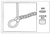
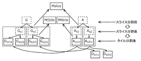
- FIG. 37 is a diagram showing an example of division of slices and tiles according to the fifth embodiment.
- FIG. 38 is a diagram showing an example of a division pattern of slices and tiles according to the fifth embodiment.
- FIG. 39 is a block diagram of the first encoding unit according to the sixth embodiment.
- FIG. 40 is a block diagram of the first decoding unit according to the sixth embodiment.
- FIG. 41 is a diagram showing an example of tile shapes according to the sixth embodiment.
- FIG. 42 is a diagram showing an example of tiles and slices according to the sixth embodiment.
- FIG. 43 is a block diagram of a dividing unit according to the sixth embodiment.
- FIG. 44 is a diagram showing an example of a map in which the point cloud data according to the sixth embodiment is viewed from above.
- FIG. 44 is a diagram showing an example of a map in which the point cloud data according to the sixth embodiment is viewed from above.
- FIG. 45 is a diagram showing an example of tile division according to the sixth embodiment.
- FIG. 46 is a diagram showing an example of tile division according to the sixth embodiment.
- FIG. 47 is a diagram showing an example of tile division according to the sixth embodiment.
- FIG. 48 is a diagram showing an example of tile data stored in the server according to the sixth embodiment.
- FIG. 49 is a diagram showing a system regarding tile division according to the sixth embodiment.
- FIG. 50 is a diagram showing an example of slice division according to the sixth embodiment.
- FIG. 51 is a diagram showing an example of the dependency relationship according to the sixth embodiment.
- FIG. 52 is a diagram showing an example of the decoding order of data according to the sixth embodiment.
- FIG. 53 is a diagram showing an example of encoded data of tiles according to the sixth embodiment.
- FIG. 54 is a block diagram of a coupling unit according to the sixth embodiment.
- FIG. 55 is a diagram showing a configuration example of encoded data and NAL units according to the sixth embodiment.
- FIG. 56 is a flowchart of the encoding process according to the sixth embodiment.
- FIG. 57 is a flowchart of the decoding process according to the sixth embodiment.
- FIG. 58 is a diagram showing a syntax example of tile additional information according to the sixth embodiment.
- FIG. 59 is a block diagram of an encoding/decoding system according to the sixth embodiment.
- FIG. 60 is a diagram showing a syntax example of slice additional information according to the sixth embodiment.
- FIG. 61 is a flowchart of the encoding process according to the sixth embodiment.
- FIG. 62 is a flowchart of the decoding process according to the sixth embodiment.
- FIG. 63 is a flowchart of the encoding process according to the sixth embodiment.
- FIG. 64 is a flowchart of the decoding process according to the sixth embodiment.
- FIG. 65 is a diagram showing an example of a division method according to the seventh embodiment.
- FIG. 66 is a diagram showing an example of division of the point cloud data according to the seventh embodiment.
- FIG. 67 is a diagram showing a syntax example of tile additional information according to the seventh embodiment.
- FIG. 68 is a diagram showing an example of index information according to the seventh embodiment.
- FIG. 69 is a diagram showing an example of the dependency relationship according to the seventh embodiment.
- FIG. 70 is a diagram showing an example of transmission data according to the seventh embodiment.
- FIG. 71 is a diagram showing a configuration example of the NAL unit according to the seventh embodiment.
- FIG. 72 is a diagram showing an example of the dependency relationship according to the seventh embodiment.
- FIG. 73 is a diagram showing an example of the decoding order of data according to the seventh embodiment.
- FIG. 74 is a diagram showing an example of the dependency relationship according to the seventh embodiment.
- FIG. 75 is a diagram showing an example of the decoding order of data according to the seventh embodiment.
- FIG. 76 is a flowchart of the encoding process according to the seventh embodiment.
- FIG. 77 is a flowchart of the decoding process according to the seventh embodiment.
- FIG. 78 is a flowchart of the encoding process according to the seventh embodiment.
- FIG. 80 is a diagram showing an example of transmission data and reception data according to the seventh embodiment.
- FIG. 81 is a flowchart of the decoding process according to the seventh embodiment.
- FIG. 82 is a diagram showing an example of transmission data and reception data according to the seventh embodiment.
- FIG. 83 is a flowchart of the decoding process according to the seventh embodiment.
- FIG. 84 is a flowchart of the encoding process according to the seventh embodiment.
- FIG. 85 is a diagram showing an example of index information according to the seventh embodiment.
- FIG. 86 is a diagram showing an example of the dependency relationship according to the seventh embodiment.
- FIG. 87 is a diagram showing an example of transmission data according to the seventh embodiment.
- FIG. 88 is a diagram showing an example of transmission data and reception data according to the seventh embodiment.
- FIG. 89 is a flowchart of the decoding process according to the seventh embodiment.
- FIG. 90 is a flowchart of the encoding process according to the seventh embodiment.
- FIG. 91 is a flowchart of the decoding process according to the seventh embodiment.
- FIG. 92 is a block diagram showing an example of the configuration of the three-dimensional data encoding device according to the eighth embodiment.
- FIG. 93 is a diagram for explaining the outline of the encoding method by the three-dimensional data encoding device according to the eighth embodiment.
- FIG. 94 is a diagram for explaining the first example of the position shift according to the eighth embodiment.
- FIG. 95 is a diagram for explaining the second example of the position shift according to the eighth embodiment.
- FIG. 96 is a flowchart showing an example of the encoding method according to the eighth embodiment.
- FIG. 97 is a flowchart showing an example of the decoding method according to the eighth embodiment.
- FIG. 98 is a diagram for explaining the third example of the position shift according to the eighth embodiment.
- FIG. 99 is a flowchart showing an example of the encoding method according to the eighth embodiment.
- FIG. 100 is a flowchart showing an example of the decoding method according to the eighth embodiment.
- FIG. 101 is a diagram for explaining the fourth example of the position shift according to the eighth embodiment.
- FIG. 102 is a flowchart showing an example of the encoding method according to the eighth embodiment.
- FIG. 103 is a diagram for explaining the fifth example of the position shift according to the eighth embodiment.
- FIG. 104 is a diagram for explaining the encoding method according to the eighth embodiment.
- FIG. 105 is a diagram showing an example of GPS syntax according to the eighth embodiment.
- FIG. 106 is a diagram showing an example of the syntax of the header of the position information according to the eighth embodiment.
- FIG. 107 is a flowchart showing an example of an encoding method for switching the processing according to the eighth embodiment.
- FIG. 108 is a flowchart showing an example of the decoding method for switching the processing according to the eighth embodiment.
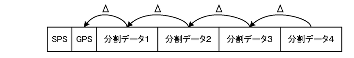
- FIG. 109 is a diagram illustrating an example of a data structure of a bitstream according to Embodiment 8.
- FIG. 110 shows an example in which the divided data of FIG.
- FIG. 111 is a diagram showing another example of the divided area according to the eighth embodiment.
- FIG. 112 is a diagram showing another example of the divided area according to the eighth embodiment.
- FIG. 113 is a diagram showing another example of the divided area according to the eighth embodiment.
- FIG. 114 is a diagram showing another example of divided areas according to the eighth embodiment.
- FIG. 115 is a diagram showing another example of the data structure according to the eighth embodiment.
- FIG. 116 is a diagram showing another example of the data structure according to the eighth embodiment.
- FIG. 117 is a diagram showing another example of the data structure according to the eighth embodiment.
- FIG. 118 is a diagram showing another example of the data structure according to the eighth embodiment.
- FIG. 119 is a diagram showing another example of the data structure according to the eighth embodiment.
- FIG. 120 is a flowchart of the encoding process according to the eighth embodiment.
- FIG. 121 is a flowchart of the decoding process according to the eighth embodiment.
- a three-dimensional data encoding method is a three-dimensional data encoding method for encoding point group data indicating a plurality of three-dimensional positions in a three-dimensional space, wherein the point group data is first
- the point cloud data is divided into a plurality of sub-point cloud data by moving the three-dimensional space into a plurality of sub-spaces by moving by the moving amount, and the point cloud data after moving by the first moving amount.
- the sub point group data For each of the plurality of sub point group data included in, the sub point group data is moved by a second movement amount based on the position of the sub space in which the sub point group data is included, and the plurality of sub points after the movement
- a bitstream is generated by encoding the group data, and the bitstream includes first movement information for calculating the first movement amount and a plurality of the plurality of sub-point group data obtained by moving the plurality of sub-point group data. It includes a plurality of second movement information for calculating each of the two movement amounts.
- the divided sub point cloud data is encoded after being moved, the amount of position information of each sub point cloud data can be reduced and the encoding efficiency can be improved.
- each of the plurality of second movement information includes the number of the plurality of subspaces and a first identification for identifying a corresponding subspace. It may include information.
- the information amount of the second movement information can be reduced and the coding efficiency can be improved.
- the first identification information may be a Morton order corresponding to each of the plurality of subspaces.
- each of the plurality of subspaces is a space obtained by dividing one three-dimensional space using an octree
- the bitstream is obtained by dividing the plurality of subspaces using an octree.
- the second identification information indicating the space and the depth information indicating the depth of the octree may be included.
- the point cloud data in the three-dimensional space is divided using an octree, the amount of position information of each sub point cloud data can be reduced, and the coding efficiency can be improved.
- the division may be performed after moving the point cloud data by the first movement amount.
- a three-dimensional data decoding method uses a plurality of sub point group data obtained by dividing point group data indicating a plurality of three-dimensional positions by dividing a three-dimensional space into a plurality of sub spaces. And a plurality of sub-point cloud data sets, each of which has been moved by a first movement amount and a corresponding second movement amount, first movement information for calculating the first movement amount, and the plurality of sub-points.
- a plurality of second movement information for respectively calculating the plurality of second movement amounts obtained by moving the point cloud data is decoded from the bitstream, and each of the plurality of sub point cloud data is subjected to the first movement.
- the point cloud data may be restored by moving an amount and a moving amount obtained by adding the corresponding second moving amount.
- each of the plurality of second movement information includes the number of the plurality of subspaces and a first identification for identifying a corresponding subspace. It may include information.
- the first identification information may be a Morton order corresponding to each of the plurality of subspaces.
- each of the plurality of subspaces is a space obtained by dividing one three-dimensional space using an octree
- the bitstream is obtained by dividing the plurality of subspaces using an octree.
- the second identification information indicating the space and the depth information indicating the depth of the octree may be included.
- a three-dimensional data encoding device is a three-dimensional data encoding device that encodes point group data indicating a plurality of three-dimensional positions in a three-dimensional space, including a processor, a memory, and And the processor uses the memory to move the point cloud data by a first movement amount and divide the three-dimensional space into a plurality of sub-spaces, thereby converting the point cloud data into a plurality of sub-points.
- a bitstream is generated by moving the sub-point cloud data by an amount of movement and encoding the plurality of sub-point cloud data after movement, and the bitstream is a first bit for calculating the first amount of movement.
- the divided sub point cloud data is encoded after being moved, the amount of position information of each sub point cloud data can be reduced and the encoding efficiency can be improved.
- a three-dimensional data decoding device includes a processor and a memory, and the processor uses the memory to divide a three-dimensional space into a plurality of sub-spaces to thereby form a plurality of cubics.
- a plurality of sub point cloud data obtained by dividing the point cloud data indicating the original position, each of which is moved by a first movement amount and a corresponding second movement amount; From the bitstream, first movement information for calculating one movement amount and a plurality of second movement information for calculating each of the plurality of second movement amounts obtained by moving the plurality of sub-point cloud data are provided.
- the point cloud data may be restored by decoding and moving each of the plurality of sub-point group data by the moving amount obtained by adding the first moving amount and the corresponding second moving amount.
- a recording medium such as a system, a method, an integrated circuit, a computer program or a computer-readable CD-ROM, and the system, the method, the integrated circuit, the computer program. And may be realized by any combination of recording media.
- a three-dimensional data encoding method and a three-dimensional data encoding device for providing a function of transmitting and receiving necessary information according to the application in the encoded data of the three-dimensional point cloud, and the code 3D data decoding method and 3D data decoding device for decoding encoded data, 3D data multiplexing method for multiplexing the encoded data, and 3D data transmission method for transmitting the encoded data To do.
- the first encoding method and the second encoding method are being studied as the encoding method (encoding method) of the point cloud data.
- the configuration of the encoded data and the encoded data system The method of storing in the format is not defined, and there is a problem that MUX processing (multiplexing) in the encoding unit, or transmission or storage cannot be performed as it is.
- PCC Point Cloud Compression
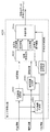
- FIG. 1 is a diagram showing a configuration example of a three-dimensional data encoding/decoding system according to the present embodiment.
- the 3D data encoding/decoding system includes a 3D data encoding system 4601, a 3D data decoding system 4602, a sensor terminal 4603, and an external connection unit 4604.
- the three-dimensional data encoding system 4601 generates encoded data or multiplexed data by encoding the point cloud data that is three-dimensional data.
- the three-dimensional data encoding system 4601 may be a three-dimensional data encoding device realized by a single device or may be a system realized by a plurality of devices.
- the three-dimensional data encoding device may include a part of the plurality of processing units included in the three-dimensional data encoding system 4601.
- the three-dimensional data encoding system 4601 includes a point cloud data generation system 4611, a presentation unit 4612, an encoding unit 4613, a multiplexing unit 4614, an input/output unit 4615, and a control unit 4616.
- the point cloud data generation system 4611 includes a sensor information acquisition unit 4617 and a point cloud data generation unit 4618.
- the sensor information acquisition unit 4617 acquires sensor information from the sensor terminal 4603 and outputs the sensor information to the point cloud data generation unit 4618.
- the point cloud data generation unit 4618 generates point cloud data from the sensor information and outputs the point cloud data to the encoding unit 4613.
- the presentation unit 4612 presents sensor information or point cloud data to the user. For example, the presentation unit 4612 displays information or an image based on sensor information or point cloud data.
- the encoding unit 4613 encodes (compresses) the point cloud data, and outputs the obtained encoded data, the control information obtained in the encoding process, and other additional information to the multiplexing unit 4614.
- the additional information includes, for example, sensor information.
- the multiplexing unit 4614 generates multiplexed data by multiplexing the encoded data input from the encoding unit 4613, the control information, and the additional information.
- the format of the multiplexed data is, for example, a file format for storage or a packet format for transmission.
- the input/output unit 4615 (eg, communication unit or interface) outputs the multiplexed data to the outside.
- the multiplexed data is stored in a storage unit such as an internal memory.
- the control unit 4616 (or the application execution unit) controls each processing unit. That is, the control unit 4616 performs control such as encoding and multiplexing.
- the sensor information may be input to the encoding unit 4613 or the multiplexing unit 4614.
- the input/output unit 4615 may output the point cloud data or the encoded data as it is to the outside.
- the transmission signal (multiplexed data) output from the three-dimensional data encoding system 4601 is input to the three-dimensional data decoding system 4602 via the external connection unit 4604.
- the 3D data decoding system 4602 generates point cloud data, which is 3D data, by decoding encoded data or multiplexed data.
- the three-dimensional data decoding system 4602 may be a three-dimensional data decoding device realized by a single device or may be a system realized by a plurality of devices.
- the three-dimensional data decoding device may include a part of the plurality of processing units included in the three-dimensional data decoding system 4602.
- the three-dimensional data decoding system 4602 includes a sensor information acquisition unit 4621, an input/output unit 4622, a demultiplexing unit 4623, a decoding unit 4624, a presentation unit 4625, a user interface 4626, and a control unit 4627.
- the sensor information acquisition unit 4621 acquires sensor information from the sensor terminal 4603.
- the input/output unit 4622 acquires the transmission signal, decodes the multiplexed data (file format or packet) from the transmission signal, and outputs the multiplexed data to the demultiplexing unit 4623.
- the demultiplexing unit 4623 acquires the encoded data, the control information and the additional information from the multiplexed data, and outputs the encoded data, the control information and the additional information to the decoding unit 4624.
- the decoding unit 4624 reconstructs the point cloud data by decoding the encoded data.
- the presentation unit 4625 presents the point cloud data to the user. For example, the presentation unit 4625 displays information or an image based on the point cloud data.
- the user interface 4626 acquires an instruction based on a user operation.
- the control unit 4627 (or the application execution unit) controls each processing unit. That is, the control unit 4627 performs control such as demultiplexing, decoding and presentation.
- the input/output unit 4622 may directly acquire the point cloud data or the encoded data from the outside.
- the presentation unit 4625 may acquire additional information such as sensor information and present the information based on the additional information. Further, the presentation unit 4625 may perform the presentation based on the user instruction acquired by the user interface 4626.
- the sensor terminal 4603 generates sensor information which is information obtained by the sensor.
- the sensor terminal 4603 is a terminal equipped with a sensor or a camera, and includes, for example, a moving object such as an automobile, a flying object such as an airplane, a mobile terminal, or a camera.
- the sensor information that can be acquired by the sensor terminal 4603 is, for example, (1) the distance between the sensor terminal 4603 and an object, or the reflectance of the object, which is obtained from LIDAR, a millimeter wave radar, or an infrared sensor; Is the distance between the camera and the object obtained from the monocular camera image or the stereo camera image, the reflectance of the object, or the like.
- the sensor information may include the orientation, orientation, gyro (angular velocity), position (GPS information or altitude), velocity, acceleration, etc. of the sensor.
- the sensor information may include temperature, atmospheric pressure, humidity, magnetism, or the like.
- the external connection unit 4604 is realized by an integrated circuit (LSI or IC), an external storage unit, communication with a cloud server via the Internet, broadcasting, or the like.
- LSI integrated circuit
- IC integrated circuit
- FIG. 2 is a diagram showing the structure of point cloud data.
- FIG. 3 is a diagram showing a configuration example of a data file in which information on point cloud data is described.
- ⁇ Point cloud data includes data of multiple points.
- the data of each point includes position information (three-dimensional coordinates) and attribute information for the position information.
- a set of multiple points is called a point cloud.
- the point cloud indicates a three-dimensional shape of an object (object).
- Positional information such as three-dimensional coordinates may be called geometry.
- the data of each point may include attribute information (attribute) of a plurality of attribute types.
- the attribute type is, for example, color or reflectance.
- One piece of attribute information may be associated with one piece of location information, or one piece of location information may be associated with pieces of attribute information having a plurality of different attribute types. Further, a plurality of pieces of attribute information of the same attribute type may be associated with one piece of position information.
- the configuration example of the data file shown in FIG. 3 is an example of the case where the position information and the attribute information have a one-to-one correspondence, and shows the position information and the attribute information of N points forming the point cloud data. There is.
- the position information is, for example, information on three axes of x, y, and z.
- the attribute information is, for example, RGB color information.
- a typical file is a ply file.
- FIG. 4 is a diagram showing types of point cloud data. As shown in FIG. 4, the point cloud data includes static objects and dynamic objects.
- Statistic object is 3D point cloud data at any time (some time).
- a dynamic object is three-dimensional point cloud data that changes with time.
- the three-dimensional point cloud data at a certain time will be referred to as a PCC frame or a frame.
- the object may be a point cloud whose area is limited to some extent, such as normal video data, or a large-scale point cloud whose area is not limited, such as map information.
- point cloud data of various densities there are point cloud data of various densities, and sparse point cloud data and dense point cloud data may exist.
- the sensor information is acquired by various methods such as a distance sensor such as a LIDAR or a range finder, a stereo camera, or a combination of a plurality of monocular cameras.
- the point cloud data generation unit 4618 generates point cloud data based on the sensor information obtained by the sensor information acquisition unit 4617.
- the point cloud data generation unit 4618 generates position information as point cloud data and adds attribute information for the position information to the position information.
- the point cloud data generation unit 4618 may process the point cloud data when generating the position information or adding the attribute information. For example, the point cloud data generation unit 4618 may reduce the data amount by deleting the point cloud whose positions overlap. Further, the point cloud data generation unit 4618 may convert the position information (position shift, rotation, normalization, etc.), or may render the attribute information.
- point cloud data generation system 4611 is included in the three-dimensional data encoding system 4601 in FIG. 1, it may be independently provided outside the three-dimensional data encoding system 4601.
- the coding unit 4613 generates coded data by coding the point cloud data based on a coding method defined in advance.
- a coding method There are the following two types of encoding methods.
- the first is a coding method using position information, and this coding method will be hereinafter referred to as a first coding method.
- the second is a coding method using a video codec, and this coding method is hereinafter referred to as a second coding method.
- the decoding unit 4624 decodes the point cloud data by decoding the coded data based on the coding method defined in advance.
- the multiplexing unit 4614 generates multiplexed data by multiplexing encoded data using an existing multiplexing method.
- the generated multiplexed data is transmitted or stored.
- the multiplexing unit 4614 multiplexes other media such as video, audio, subtitles, applications, files, or reference time information, in addition to the PCC encoded data. Also, the multiplexing unit 4614 may further multiplex attribute information related to the sensor information or the point cloud data.
- ISOBMFF ISOBMFF-based transmission methods such as MPEG-DASH, MMT, MPEG-2 TS Systems, and RMP.
- the demultiplexing unit 4623 extracts PCC encoded data, other media, time information, etc. from the multiplexed data.
- the input/output unit 4615 transmits the multiplexed data using a method suitable for the medium to be transmitted or the medium to be stored, such as broadcasting or communication.
- the input/output unit 4615 may communicate with another device via the Internet, or may communicate with a storage unit such as a cloud server.
- http http, ftp, TCP, UDP, etc. are used.
- a PULL type communication method may be used, or a PUSH type communication method may be used.
- Either wired transmission or wireless transmission may be used.
- Ethernet registered trademark
- USB registered trademark
- RS-232C HDMI
- coaxial cable or the like is used.
- wireless transmission wireless LAN, Wi-Fi (registered trademark), Bluetooth (registered trademark), millimeter wave, or the like is used.
- DVB-T2, DVB-S2, DVB-C2, ATSC3.0, or ISDB-S3 is used as the broadcasting system.
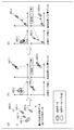
- FIG. 5 is a diagram showing a configuration of a first encoding unit 4630 that is an example of an encoding unit 4613 that performs encoding of the first encoding method.
- FIG. 6 is a block diagram of the first encoding unit 4630.
- the first coding unit 4630 generates coded data (coded stream) by coding the point cloud data by the first coding method.
- the first encoding unit 4630 includes a position information encoding unit 4631, an attribute information encoding unit 4632, an additional information encoding unit 4633, and a multiplexing unit 4634.
- the first encoding unit 4630 has a feature of performing encoding while being aware of the three-dimensional structure.
- the first encoding unit 4630 has a characteristic that the attribute information encoding unit 4632 performs encoding using the information obtained from the position information encoding unit 4631.
- the first encoding method is also called GPCC (Geometry based PCC).
- the point cloud data is PCC point cloud data such as a PLY file or PCC point cloud data generated from sensor information, and includes position information (Position), attribute information (Attribute), and other additional information (MetaData). including.
- the position information is input to the position information encoding unit 4631, the attribute information is input to the attribute information encoding unit 4632, and the additional information is input to the additional information encoding unit 4633.
- the position information encoding unit 4631 generates encoded position information (Compressed Geometry) that is encoded data by encoding the position information.
- the position information encoding unit 4631 encodes position information using an N-ary tree structure such as an octree. Specifically, in the octree, the target space is divided into eight nodes (subspaces), and 8-bit information (occupancy code) indicating whether or not each node includes a point cloud is generated. .. The node including the point cloud is further divided into eight nodes, and 8-bit information indicating whether or not each of the eight nodes includes the point cloud is generated. This process is repeated until the number of points included in a predetermined hierarchy or node is equal to or less than the threshold value.
- the attribute information encoding unit 4632 generates encoded attribute information (Compressed Attribute) that is encoded data by performing encoding using the configuration information generated by the position information encoding unit 4631. For example, the attribute information encoding unit 4632 determines a reference point (reference node) to be referred to in encoding the target point (target node) to be processed, based on the octree structure generated by the position information encoding unit 4631. To do. For example, the attribute information encoding unit 4632 refers to a peripheral node or an adjacent node whose parent node in the octree is the same as the target node. The method of determining the reference relationship is not limited to this.
- the attribute information encoding process may include at least one of a quantization process, a prediction process, and an arithmetic encoding process.
- the reference refers to using the reference node to calculate the predicted value of the attribute information, or the state of the reference node in determining the encoding parameter (for example, occupancy indicating whether the reference node includes a point cloud or not). Information).
- the encoding parameter is a quantization parameter in quantization processing, a context in arithmetic encoding, or the like.
- the additional information encoding unit 4633 generates encoded additional information (Compressed MetaData) that is encoded data by encoding compressible data in the additional information.
- compressed MetaData encoded additional information
- the multiplexing unit 4634 multiplexes the coding position information, the coding attribute information, the coding additional information, and other additional information to generate a coded stream (Compressed Stream) that is coded data.
- the generated coded stream is output to the processing unit of the system layer (not shown).
- FIG. 7 is a diagram showing the configuration of the first decoding unit 4640.
- FIG. 8 is a block diagram of the first decoding unit 4640.
- the first decoding unit 4640 generates point cloud data by decoding the coded data (coded stream) coded by the first coding method by the first coding method.
- the first decoding unit 4640 includes a demultiplexing unit 4641, a position information decoding unit 4642, an attribute information decoding unit 4643, and an additional information decoding unit 4644.
- An encoded stream (Compressed Stream) that is encoded data is input to the first decoding unit 4640 from a processing unit of a system layer (not shown).
- the demultiplexing unit 4641 separates encoded position information (Compressed Geometry), encoded attribute information (Compressed Attribute), encoded additional information (Compressed MetaData), and other additional information from the encoded data.
- the position information decoding unit 4642 generates position information by decoding the coded position information. For example, the position information decoding unit 4642 restores the position information of the point group represented by the three-dimensional coordinates from the encoded position information represented by the N-tree structure such as an octree.
- the attribute information decoding unit 4643 decodes the encoded attribute information based on the configuration information generated by the position information decoding unit 4642. For example, the attribute information decoding unit 4643 determines the reference point (reference node) to be referred in decoding the target point (target node) to be processed, based on the octree structure obtained by the position information decoding unit 4642. For example, the attribute information decoding unit 4643 refers to, among the peripheral nodes or adjacent nodes, the node whose parent node in the octree is the same as the target node. The method of determining the reference relationship is not limited to this.
- the attribute information decoding process may include at least one of a dequantization process, a prediction process, and an arithmetic decoding process.
- the reference refers to using the reference node to calculate the predicted value of the attribute information, or the state of the reference node in determining the decoding parameter (for example, occupancy information indicating whether the reference node includes a point cloud or not). ) Is used.
- the decoding parameter is a quantization parameter in inverse quantization processing, a context in arithmetic decoding, or the like.
- the additional information decoding unit 4644 generates additional information by decoding the encoded additional information. Also, the first decoding unit 4640 uses the additional information necessary for the decoding process of the position information and the attribute information at the time of decoding, and outputs the additional information necessary for the application to the outside.
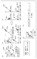
- FIG. 9 is a diagram showing the configuration of the second encoding unit 4650.
- FIG. 10 is a block diagram of the second encoding unit 4650.
- the second encoding unit 4650 generates encoded data (encoded stream) by encoding the point cloud data by the second encoding method.
- the second encoding unit 4650 includes an additional information generating unit 4651, a position image generating unit 4652, an attribute image generating unit 4653, a video encoding unit 4654, an additional information encoding unit 4655, and a multiplexing unit 4656. Including and
- the second encoding unit 4650 generates the position image and the attribute image by projecting the three-dimensional structure on the two-dimensional image, and encodes the generated position image and the attribute image using the existing video encoding method. It has the feature.
- the second encoding method is also called VPCC (Video based PCC).
- the point cloud data is PCC point cloud data such as a PLY file, or PCC point cloud data generated from sensor information, and includes position information (Position), attribute information (Attribute), and other additional information MetaData). Including.
- the additional information generation unit 4651 generates map information of a plurality of two-dimensional images by projecting the three-dimensional structure on a two-dimensional image.
- the position image generation unit 4652 generates a position image (Geometry Image) based on the position information and the map information generated by the additional information generation unit 4651.
- This position image is, for example, a distance image in which a distance (Depth) is shown as a pixel value.
- this range image may be an image in which a plurality of point groups are viewed from one viewpoint (an image in which a plurality of point groups are projected on one two-dimensional plane), or a plurality of point groups from a plurality of viewpoints. It may be a plurality of images viewed, or may be a single image obtained by integrating these plurality of images.
- the attribute image generating unit 4653 generates an attribute image based on the attribute information and the map information generated by the additional information generating unit 4651.
- This attribute image is, for example, an image in which attribute information (for example, color (RGB)) is shown as a pixel value.
- RGB color
- this image may be an image in which a plurality of point clouds are viewed from one viewpoint (an image obtained by projecting a plurality of point groups on one two-dimensional plane), or a plurality of point groups may be viewed from a plurality of viewpoints. It may be a plurality of viewed images or one image obtained by integrating these plurality of images.
- the video encoding unit 4654 encodes the position image and the attribute image by using the video encoding method, so that the encoded position image (Compressed Geometry Image) and the encoded attribute image (Compressed Attribute Image) are encoded data. ) Is generated.
- Any known encoding method may be used as the video encoding method.
- the video encoding method is AVC, HEVC, or the like.
- the additional information encoding unit 4655 generates encoded additional information (Compressed MetaData) by encoding the additional information included in the point cloud data, the map information, and the like.
- the multiplexing unit 4656 generates a coded stream (Compressed Stream) that is coded data by multiplexing the coded position image, the coded attribute image, the coded additional information, and other additional information.
- the generated coded stream is output to the processing unit of the system layer (not shown).
- FIG. 11 is a diagram showing the configuration of the second decoding unit 4660.
- FIG. 12 is a block diagram of the second decoding unit 4660.
- the second decoding unit 4660 generates point cloud data by decoding the coded data (coded stream) coded by the second coding method by the second coding method.
- the second decoding unit 4660 includes a demultiplexing unit 4661, a video decoding unit 4662, an additional information decoding unit 4663, a position information generation unit 4664, and an attribute information generation unit 4665.
- An encoded stream (Compressed Stream) that is encoded data is input to the second decoding unit 4660 from a processing unit of a system layer (not shown).
- the demultiplexing unit 4661 separates the encoded position image (Compressed Geometry Image), the encoded attribute image (Compressed Attribute Image), the encoded additional information (Compressed MetaData), and other additional information from the encoded data. ..
- the video decoding unit 4662 generates the position image and the attribute image by decoding the encoded position image and the encoded attribute image using the video encoding method.
- Any known encoding method may be used as the video encoding method.
- the video encoding method is AVC, HEVC, or the like.
- the additional information decoding unit 4663 generates additional information including map information by decoding the encoded additional information.
- the position information generation unit 4664 generates position information using the position image and map information.
- the attribute information generation unit 4665 generates attribute information using the attribute image and map information.
- the second decryption unit 4660 uses the additional information required for the decryption at the time of decryption and outputs the additional information required for the application to the outside.
- FIG. 13 is a diagram showing a protocol stack related to PCC encoded data.
- FIG. 13 shows an example in which data of another medium such as video (for example, HEVC) or audio is multiplexed with PCC encoded data and transmitted or stored.
- video for example, HEVC
- audio is multiplexed with PCC encoded data and transmitted or stored.
- the multiplexing method and file format have the function to multiplex various encoded data and transmit or store them.
- the coded data In order to transmit or store the coded data, the coded data must be converted into a multiplexing format.
- HEVC defines a technique of storing encoded data in a data structure called a NAL unit and storing the NAL unit in ISOBMFF.
- the first encoding method (Codec1) and the second encoding method (Codec2) are being studied as the encoding method of the point cloud data, but the configuration of the encoded data and the encoded data are The method of storing in the system format is not defined, and there is a problem that MUX processing (multiplexing), transmission, and storage in the encoding unit cannot be performed as they are.
- ISOBMFF ISO based media file format
- ISOBMFF ISO based media file format
- ISOBMFF is a standard that does not depend on media, which defines a format in which various media such as video, audio, and text can be multiplexed and stored.
- the basic unit in ISOBMFF is a box.
- a box is composed of type, length, and data, and a set is a file in which boxes of various types are combined.
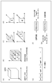
- FIG. 14 is a diagram showing a basic structure (file) of ISOBMFF.
- the ISOBMFF file mainly includes boxes such as ftyp that indicates the brand of the file by 4CC (4 character code), moov that stores metadata such as control information, and mdat that stores data.
- the storage method for each media in the ISOBMFF file is separately specified.
- the storage method for AVC video and HEVC video is specified in ISO/IEC 14496-15.
- ISO/IEC 14496-15 it is conceivable that the function of ISOBMFF is expanded and used to store or transmit the PCC encoded data, but there is no provision yet to store the PCC encoded data in the ISOBMFF file. Therefore, in this embodiment, a method of storing PCC encoded data in an ISOBMFF file will be described.
- FIG. 15 is a diagram showing a protocol stack when a NAL unit common to PCC codecs is stored in an ISOBMFF file.
- the NAL unit common to the PCC codec is stored in the ISOBMFF file.
- the NAL unit is common to the PCC codecs, but since multiple PCC codecs are stored in the NAL unit, it is desirable to specify the storage method (Carryage of Codec1, Carriage of Codec2) according to each codec.
- FIG. 16 is a diagram showing an example in which a common PCC NAL unit is stored in an ISOBMFF file of the storage method (Carriage of Codec 1) of codec 1.
- FIG. 17 is a diagram showing an example in which a common PCC NAL unit is stored in an ISOBMFF file according to the storage method (Carriage of Codec 2) of codec 2.
- ftyp is important information for identifying the file format, and a different identifier is defined for each codec for ftyp.
- pcc1 indicates that PCC codec 1 (first encoding method) is used.
- pcc2 indicates that the PCC codec 2 (second encoding method) is used. That is, pcc1 and pcc2 indicate that the data is PCC (coded data of three-dimensional data (point cloud data)), and also indicate the PCC codec (first coding method and second coding method). ..
- the multiplexing unit stores the NAL unit in, for example, moov or mdat in a predetermined method.
- the multiplexing unit stores the NAL unit in, for example, moov or mdat in a predetermined method.
- the multiplexing unit may store the NAL unit size in the NAL unit as in HEVC.
- the PCC encoded data is encoded by the first encoding method or encoded by the second encoding method. It is possible to determine whether or not it has been converted. Further, as described above, it is encoded by both encoding methods by determining whether the PCC encoded data is encoded by the first encoding method or the second encoding method. It is possible to extract the encoded data encoded by either one of the encoding methods from the data in which the encoded data is mixed. This makes it possible to suppress the amount of data to be transmitted when transmitting encoded data. Further, according to this storage method, a common data format can be used between the first encoding method and the second encoding method without setting different data (file) formats.
- the multiplexing unit may store the NAL unit from which pcc_nal_unit_type is deleted in the ISOBMFF file.
- the multiplexing unit included in the three-dimensional data encoding system (three-dimensional data encoding device) according to the present embodiment and the three-dimensional data decoding system (three-dimensional data decoding device) according to the present embodiment will be described.
- the configuration and operation of the provided demultiplexer will be described.
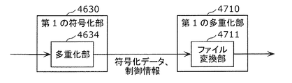
- FIG. 18 is a diagram showing the configuration of the first multiplexing unit 4710.
- the first multiplexing unit 4710 generates the multiplexed data (file) by storing the encoded data and control information (NAL unit) generated by the first encoding unit 4630 in the ISOBMFF file.
- the portion 4711 is provided.
- the first multiplexing unit 4710 is included in, for example, the multiplexing unit 4614 shown in FIG.
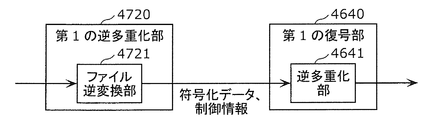
- FIG. 19 is a diagram showing the configuration of the first demultiplexing unit 4720.
- the first demultiplexing unit 4720 acquires encoded data and control information (NAL unit) from the multiplexed data (file), and outputs the obtained encoded data and control information to the first decoding unit 4640.
- the inverse conversion unit 4721 is provided.
- the first demultiplexing unit 4720 is included in the demultiplexing unit 4623 shown in FIG. 1, for example.
- FIG. 20 is a diagram showing the configuration of the second multiplexing unit 4730.
- the second multiplexing unit 4730 stores the encoded data and the control information (NAL unit) generated by the second encoding unit 4650 in the ISOBMFF file to generate the multiplexed data (file) File conversion
- the portion 4731 is provided.
- the second multiplexing unit 4730 is included in the multiplexing unit 4614 shown in FIG. 1, for example.
- FIG. 21 is a diagram showing the configuration of the second demultiplexing unit 4740.
- the second demultiplexing unit 4740 acquires encoded data and control information (NAL unit) from the multiplexed data (file), and outputs the obtained encoded data and control information to the second decoding unit 4660.
- the inverse conversion unit 4741 is provided.
- the second demultiplexing unit 4740 is included in the demultiplexing unit 4623 shown in FIG. 1, for example.
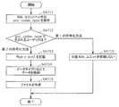
- FIG. 22 is a flowchart of the multiplexing process performed by the first multiplexing unit 4710.
- the first multiplexing unit 4710 analyzes the pcc_codec_type included in the NAL unit header to determine whether the codec used is the first coding method or the second coding method. A determination is made (S4701).
- the first multiplexing unit 4710 does not process the NAL unit (S4703).
- the first multiplexing unit 4710 when pcc_codec_type indicates the second encoding method (first encoding method in S4702), the first multiplexing unit 4710 describes pcc1 in ftype (S4704). That is, the first multiplexing unit 4710 describes in ftyp the information indicating that the data encoded by the first encoding method is stored in the file.
- the first multiplexing unit 4710 analyzes pcc_nal_unit_type included in the NAL unit header, and stores the data in a box (moov or mdat etc.) by a predetermined method according to the data type indicated by pcc_nal_unit_type (S4705). ). Then, the first multiplexing unit 4710 creates an ISOBMFF file including the ftyp and the box (S4706).
- FIG. 23 is a flowchart of the multiplexing process performed by the second multiplexing unit 4730.
- the second multiplexing unit 4730 analyzes the pcc_codec_type included in the NAL unit header to determine whether the codec used is the first coding method or the second coding method. A determination is made (S4711).
- the second multiplexing unit 4730 If pcc_unit_type indicates the second encoding method (second encoding method in S4712), the second multiplexing unit 4730 describes pcc2 in ftype (S4713). That is, the second multiplexing unit 4730 describes in ftyp the information indicating that the data encoded by the second encoding method is stored in the file.
- the second multiplexing unit 4730 analyzes pcc_nal_unit_type included in the NAL unit header, and stores the data in a box (moov or mdat etc.) by a predetermined method according to the data type indicated by pcc_nal_unit_type (S4714). ). Then, the second multiplexing unit 4730 creates an ISOBMFF file including the ftyp and the box (S4715).
- the second multiplexing unit 4730 does not process the NAL unit (S4716).
- the above process shows an example in which PCC data is encoded by either the first encoding method or the second encoding method.
- the first multiplexing unit 4710 and the second multiplexing unit 4730 store a desired NAL unit in a file by identifying the codec type of the NAL unit.
- the PCC codec identification information is included in addition to the NAL unit header, the first multiplexing unit 4710 and the second multiplexing unit 4730 are included in other than the NAL unit header in steps S4701 and S4711.
- the identification information of the PCC codec may be used to identify the codec type (first encoding method or second encoding method).
- the first multiplexing unit 4710 and the second multiplexing unit 4730 may delete the pcc_nal_unit_type from the NAL unit header when storing the data in the file in steps S4706 and S4714, and then store the data in the file. Good.
- FIG. 24 is a flowchart showing processing by the first demultiplexing unit 4720 and the first decoding unit 4640.
- the first demultiplexing unit 4720 analyzes ftyp included in the ISOBMFF file (S4721).
- the codec indicated by ftyp is the second encoding method (pcc2) (second encoding method in S4722)
- the first demultiplexing unit 4720 determines that the data included in the payload of the NAL unit is the second. It is determined that the data is coded by the coding method of (S4723).
- the first demultiplexing unit 4720 also transfers the result of the determination to the first decoding unit 4640.
- the first decoding unit 4640 does not process the NAL unit (S4724).
- the first demultiplexing unit 4720 detects that the data included in the payload of the NAL unit is It is determined that the data is coded by the first coding method (S4725). The first demultiplexing unit 4720 also transfers the result of the determination to the first decoding unit 4640.
- the first decoding unit 4640 identifies the data as pcc_nal_unit_type included in the NAL unit header being the identifier of the NAL unit for the first encoding method (S4726). Then, the first decoding unit 4640 decodes the PCC data using the decoding process of the first coding method (S4727).
- FIG. 25 is a flowchart showing the processing by the second demultiplexing unit 4740 and the second decoding unit 4660.
- the second demultiplexing unit 4740 analyzes the ftyp included in the ISOBMFF file (S4731).
- the codec indicated by ftyp is the second coding method (pcc2) (the second coding method in S4732)
- the second demultiplexing unit 4740 determines that the data included in the payload of the NAL unit is the second. It is determined that the data is encoded by the encoding method of (S4733).
- the second demultiplexing unit 4740 also transmits the result of the determination to the second decoding unit 4660.
- the second decoding unit 4660 identifies the data as the pcc_nal_unit_type included in the NAL unit header being the identifier of the NAL unit for the second encoding method (S4734). Then, second decoding section 4660 decodes the PCC data using the decoding process of the second encoding method (S4735).
- the second demultiplexing unit 4740 determines that the data included in the payload of the NAL unit is It is determined that the data is coded by the first coding method (S4736). The second demultiplexing unit 4740 also transmits the result of the determination to the second decoding unit 4660. The second decoding unit 4660 does not process the NAL unit (S4737).
- the codec type can be identified at an early stage.
- a desired NAL unit can be input to the first decoding unit 4640 or the second decoding unit 4660 to remove unnecessary NAL units.
- the first decoding unit 4640 or the second decoding unit 4660 may not need the process of analyzing the codec identification information.
- the first decoding unit 4640 or the second decoding unit 4660 may refer to the NAL unit type again to perform a process of analyzing the codec identification information.
- NAL unit may be assigned pcc_nal_unit_type and then output to the first decoding unit 4640 or the second decoding unit 4660.
- FIG. 26 is a diagram showing configurations of encoding section 4670 and third multiplexing section 4750 according to the present embodiment.
- the encoding unit 4670 encodes the point cloud data by using one or both of the first encoding method and the second encoding method.
- the coding unit 4670 may switch the coding method (first coding method and second coding method) in units of point cloud data or in units of frames.
- the encoding unit 4670 may switch the encoding method in units that can be encoded.
- the encoding unit 4670 generates encoded data (encoded stream) including identification information of the PCC codec.
- the third multiplexing unit 4750 includes a file conversion unit 4751.
- the file conversion unit 4751 converts the NAL unit output from the encoding unit 4670 into a PCC data file.
- the file conversion unit 4751 analyzes the codec identification information included in the NAL unit header, and determines whether the PCC encoded data is data encoded by the first encoding method or encoded by the second encoding method. It is determined whether the data is encoded data or data encoded by both methods.
- the file conversion unit 4751 describes the brand name that can identify the codec in the ftyp. For example, in the case of indicating that the encoding has been performed by both methods, pccc3 is described in ftyp.
- the file conversion unit 4751 may determine the PCC codec (encoding method) using the identification information. ..
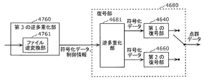
- FIG. 27 is a diagram showing configurations of the third demultiplexing section 4760 and the decoding section 4680 according to the present embodiment.
- the third demultiplexing unit 4760 includes a file deconversion unit 4761.
- the file inverse conversion unit 4761 analyzes the ftyp included in the file, and determines whether the PCC encoded data is the data encoded by the first encoding method or the data encoded by the second encoding method. Or the data is encoded by both methods.
- the data is input to the corresponding decoding unit of the first decoding unit 4640 and the second decoding unit 4660, and the other decoding is performed. No data is entered in the department.
- the PCC encoded data is encoded by both encoding methods, the data is input to the decoding unit 4680 corresponding to both types.
- the decoding unit 4680 decodes the PCC encoded data using either one or both of the first encoding method and the second encoding method.
- FIG. 28 is a flowchart showing processing by the third multiplexing unit 4750 according to this embodiment.
- the third multiplexing unit 4750 analyzes the pcc_codec_type included in the NAL unit header to determine whether the codec used is the first coding method or the second coding method. It is determined whether it is both the first encoding method and the second encoding method (S4741).
- the third multiplexing unit 4750 describes pcc2 in ftyp (S4744). That is, the third multiplexing unit 4750 describes, in ftyp, information indicating that the data encoded by the second encoding method is stored in the file.
- the third multiplexing unit 4750 analyzes pcc_nal_unit_type included in the NAL unit header, and stores the data in a box (moov or mdat etc.) in a predetermined method according to the data type indicated by pcc_unit_type (S4745). ). Then, the third multiplexing unit 4750 creates an ISOBMFF file including the ftyp and the box (S4746).
- the third multiplexing unit 4750 describes pcc1 in ftyp (S4747). That is, the third multiplexing unit 4750 describes, in ftyp, information indicating that the data encoded by the first encoding method is stored in the file.
- the third multiplexing unit 4750 analyzes pcc_nal_unit_type included in the NAL unit header, and stores the data in a box (moov or mdat etc.) by a predetermined method according to the data type indicated by pcc_unit_type (S4748). ). Then, the third multiplexing unit 4750 creates an ISOBMFF file including the ftyp and the box (S4746).
- the third multiplexing unit 4750 describes pcc3 in ftyp ( S4749). That is, the third multiplexing unit 4750 describes in ftyp the information indicating that the data encoded by both encoding methods is stored in the file.
- the third multiplexing unit 4750 analyzes pcc_nal_unit_type included in the NAL unit header, and stores the data in a box (moov or mdat etc.) in a predetermined method according to the data type indicated by pcc_unit_type (S4750). ). Then, the third multiplexing unit 4750 creates an ISOBMFF file including the ftyp and the box (S4746).
- FIG. 29 is a flowchart showing processing by the third demultiplexing unit 4760 and the decoding unit 4680.
- the third demultiplexing unit 4760 analyzes ftyp included in the ISOBMFF file (S4761).
- the codec indicated by ftyp is the second encoding method (pcc2) (Yes in S4762 and the second encoding method in S4763)
- the third demultiplexing unit 4760 is included in the payload of the NAL unit. It is determined that the data to be encoded is the data encoded by the second encoding method (S4764).
- the third demultiplexing unit 4760 transmits the result of the determination to the decoding unit 4680.
- the decoding unit 4680 identifies the data as pcc_nal_unit_type included in the NAL unit header being the identifier of the NAL unit for the second encoding method (S4765). Then, the decoding unit 4680 decodes the PCC data using the decoding process of the second coding method (S4766).
- the third demultiplexing unit 4760 causes the NAL unit payload to be transmitted. It is determined that the data included in is the data encoded by the first encoding method (S4767). Also, the third demultiplexing unit 4760 transmits the result of the determination to the decoding unit 4680.
- the decoding unit 4680 identifies the data as the pcc_nal_unit_type included in the NAL unit header being the identifier of the NAL unit for the first encoding method (S4768). Then, the decoding unit 4680 decodes the PCC data using the decoding process of the first encoding method (S4769).
- the third demultiplexing unit 4760 determines that the data included in the payload of the NAL unit is the first one. It is determined that the data is coded by both the coding method of 1 and the second coding method (S4770). Also, the third demultiplexing unit 4760 transmits the result of the determination to the decoding unit 4680.
- the decryption unit 4680 identifies the data as the pcc_nal_unit_type included in the NAL unit header being the identifier of the NAL unit for the codec described in the pcc_codec_type (S4771). Then, the decoding unit 4680 decodes the PCC data using the decoding processing of both encoding methods (S4772). That is, the decoding unit 4680 decodes the data encoded by the first encoding method using the decoding process of the first encoding method, and the data encoded by the second encoding method, Decoding is performed using the decoding process of the second encoding method.
- identification information A modification of this embodiment will be described below.
- the following types may be indicated by the identification information as the types of brands indicated by ftyp. Further, a plurality of types of combinations shown below may be indicated by the identification information.
- the identification information may indicate whether the object of the original data before PCC coding is a point cloud whose area is restricted or a large-scale point cloud whose area is not restricted like map information. ..
- the identification information may indicate whether the original data before PCC encoding is a static object or a dynamic object.
- the identification information indicates whether the PCC encoded data is the data encoded by the first encoding method or the data encoded by the second encoding method. Good.
- the identification information may indicate the algorithm used in PCC encoding.
- the algorithm is, for example, a coding method that can be used in the first coding method or the second coding method.
- the identification information may indicate the difference in the method of storing the PCC encoded data in the ISOBMFF file.
- the identification information may indicate whether the storage method used is a storage method for storage or a storage method for real-time transmission such as dynamic streaming.
- Metadata such as identification information is stored in ftyp
- these metadata may be stored in addition to ftyp.
- these metadata may be stored in moov.
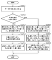
- the three-dimensional data storage device (or three-dimensional data multiplexing device or three-dimensional data encoding device) performs the processing shown in FIG.
- the three-dimensional data storage device (including, for example, the first multiplexing unit 4710, the second multiplexing unit 4730, or the third multiplexing unit 4750) generates an encoded stream in which the point cloud data is encoded.
- One or more stored units (for example, NAL units) are acquired (S4781).
- the three-dimensional data storage device stores one or more units in a file (for example, ISOBMFF file) (S4782).
- the three-dimensional data storage device stores information (for example, pcc1, pcc2, or pcc3) indicating that the data stored in the file is encoded point cloud data, It is stored in the control information (for example, ftyp) of the file.
- the device that processes the file generated by the three-dimensional data storage device determines whether the data stored in the file is the encoded data of the point cloud data by referring to the control information of the file. Whether or not it can be determined early. Therefore, the processing amount of the device can be reduced or the processing speed can be increased.
- the information further indicates a coding method used for coding the point cloud data, among the first coding method and the second coding method.
- the data stored in the file is the data obtained by encoding the point cloud data, and that the code used to encode the point cloud data among the first encoding method and the second encoding method.
- the conversion method may be indicated by a single piece of information or different pieces of information.
- the device that processes the file generated by the three-dimensional data storage device can quickly determine the codec used for the data stored in the file by referring to the control information of the file. Therefore, the processing amount of the device can be reduced or the processing speed can be increased.
- the first encoding method encodes position information in which the position of the point cloud data is represented by an N (N is an integer of 2 or more) branch tree, and encodes the attribute information using the position information (GPCC) and the second encoding method is a method (VPCC) of generating a two-dimensional image from point cloud data and encoding the two-dimensional image using a video encoding method.
- the file complies with ISOBMFF (ISO based media file format).
- the three-dimensional data storage device includes a processor and a memory, and the processor uses the memory to perform the above processing.
- the three-dimensional data acquisition device (or three-dimensional data demultiplexing device or three-dimensional data decoding device) performs the processing shown in FIG.
- the three-dimensional data acquisition device (including, for example, the first demultiplexing unit 4720, the second demultiplexing unit 4740, or the third demultiplexing unit 4760) is an encoded stream in which point cloud data is encoded.
- a file for example, an ISOBMFF file
- one or more units for example, NAL units
- the three-dimensional data acquisition device acquires one or more units from the file (S4792).
- the file control information (for example, ftyp) includes information (for example, pcc1, pcc2, or pcc3) indicating that the data stored in the file is encoded point cloud data.
- the three-dimensional data acquisition device refers to the above information and determines whether or not the data stored in the file is data in which point cloud data is encoded.
- the data in which the point cloud data included in one or more units is encoded is To generate point cloud data.
- the three-dimensional data acquisition device determines that the data stored in the file is data in which the point cloud data is encoded, the data included in one or more units is encoded in the point cloud data.
- the information indicating that the data has been processed is output (notified) to the processing unit at the subsequent stage (for example, the first decoding unit 4640, the second decoding unit 4660, or the decoding unit 4680).
- the three-dimensional data acquisition apparatus can quickly determine whether the data stored in the file is the encoded data of the point cloud data by referring to the control information of the file. Therefore, it is possible to reduce the processing amount or speed up the processing of the three-dimensional data acquisition device or the subsequent device.
- the information further indicates the coding method used for the coding, of the first coding method and the second coding method.
- the data stored in the file is the data obtained by encoding the point cloud data, and that the code used to encode the point cloud data among the first encoding method and the second encoding method.
- the conversion method may be indicated by a single piece of information or different pieces of information.
- the three-dimensional data acquisition apparatus can quickly determine the codec used for the data stored in the file by referring to the control information of the file. Therefore, it is possible to reduce the processing amount or speed up the processing of the three-dimensional data acquisition device or the subsequent device.
- the three-dimensional data acquisition device selects one of the encoded point group data including the data encoded by the first encoding method and the data encoded by the second encoding method based on the information.
- the data encoded by one of the encoding methods is acquired.
- the first encoding method encodes position information in which the position of the point cloud data is represented by an N (N is an integer of 2 or more) branch tree, and encodes the attribute information using the position information (GPCC) and the second encoding method is a method (VPCC) of generating a two-dimensional image from point cloud data and encoding the two-dimensional image using a video encoding method.
- the file complies with ISOBMFF (ISO based media file format).
- the three-dimensional data acquisition device includes a processor and a memory, and the processor uses the memory to perform the above processing.
- coded data position information (Geometry), attribute information (Attribute), additional information (Metadata) generated by the above-described first coding unit 4630 or second coding unit 4650.
- the type, the method of generating additional information (metadata), and the multiplexing process in the multiplexing unit will be described.
- the additional information (metadata) may be referred to as a parameter set or control information.
- the dynamic object (three-dimensional point cloud data that changes with time) described in FIG. 4 will be described as an example, but even in the case of a static object (three-dimensional point cloud data at an arbitrary time), Similar methods may be used.
- FIG. 32 is a diagram showing configurations of an encoding unit 4801 and a multiplexing unit 4802 included in the three-dimensional data encoding device according to this embodiment.
- the encoding unit 4801 corresponds to, for example, the above-described first encoding unit 4630 or second encoding unit 4650.
- the multiplexing unit 4802 corresponds to the above-described multiplexing unit 4634 or 4656.
- the encoding unit 4801 encodes point cloud data of a plurality of PCC (Point Cloud Compression) frames, and generates encoded data (Multiple Compressed Data) of a plurality of position information, attribute information and additional information.
- PCC Point Cloud Compression
- the multiplexing unit 4802 converts the data of a plurality of data types (position information, attribute information, and additional information) into NAL units, thereby converting the data into a data structure that considers data access in the decoding device.
- FIG. 33 is a diagram showing a configuration example of encoded data generated by the encoding unit 4801.
- the arrows in the figure show the dependency relations regarding the decoding of the encoded data, and the origin of the arrows depends on the data at the tip of the arrows. That is, the decryption device decrypts the data at the tip of the arrow and uses the decrypted data to decrypt the original data at the arrow.
- dependent means that the dependent data is referred to (used) in the processing (encoding or decoding) of the dependent data.
- the encoding unit 4801 encodes the position information of each frame to generate encoded position data (Compressed Geometry Data) for each frame.
- the encoded position data is represented by G(i). i indicates the frame number or the time of the frame.
- the encoding unit 4801 also generates a position parameter set (GPS(i)) corresponding to each frame.
- the position parameter set includes parameters that can be used to decode the encoded position data. Also, the encoded position data for each frame depends on the corresponding position parameter set.
- the encoded position data consisting of multiple frames is defined as a position sequence (Geometry Sequence).
- the encoding unit 4801 generates a position sequence parameter set (Geometry Sequence PS: also referred to as position SPS) that stores parameters commonly used in decoding processing for a plurality of frames in the position sequence.
- the position sequence depends on the position SPS.
- the encoding unit 4801 encodes the attribute information of each frame to generate encoded attribute data (Compressed Attribute Data) for each frame. Also, the encoded attribute data is represented by A(i). Further, FIG. 33 shows an example in which the attribute X and the attribute Y exist, the encoded attribute data of the attribute X is represented by AX(i), and the encoded attribute data of the attribute Y is represented by AY(i). ..
- the encoding unit 4801 also generates an attribute parameter set (APS(i)) corresponding to each frame. Further, the attribute parameter set of the attribute X is represented by AXPS(i), and the attribute parameter set of the attribute Y is represented by AYPS(i).
- the attribute parameter set includes parameters that can be used for decoding the encoded attribute information.
- the encoded attribute data depends on the corresponding attribute parameter set.
- the encoded attribute data consisting of multiple frames is defined as an attribute sequence (Attribute Sequence).
- the encoding unit 4801 generates an attribute sequence parameter set (Attribute Sequence PS: also referred to as attribute SPS) that stores parameters commonly used for decoding processing on a plurality of frames in the attribute sequence.
- attribute sequence PS also referred to as attribute SPS
- the attribute sequence depends on the attribute SPS.
- the encoding attribute data depends on the encoding position data.
- FIG. 33 shows an example in which two types of attribute information (attribute X and attribute Y) exist.
- attribute information attribute X and attribute Y
- the two encoding units generate respective data and metadata.
- an attribute sequence is defined for each type of attribute information, and an attribute SPS is generated for each type of attribute information.
- FIG. 33 shows an example in which the position information is one type and the attribute information is two types, the invention is not limited to this, and the attribute information may be one type or three or more types. Good.
- encoded data can be generated by the same method.
- the attribute information may be omitted. In that case, the encoding unit 4801 does not have to generate the parameter set related to the attribute information.
- the encoding unit 4801 generates a PCC stream PS (PCC Stream PS: stream PS) that is a parameter set of the entire PCC stream.
- the encoding unit 4801 stores, in the stream PS, parameters that can be commonly used in the decoding process for one or more position sequences and one or more attribute sequences.
- the stream PS includes identification information indicating the codec of the point cloud data, information indicating the algorithm used for encoding, and the like.
- the position sequence and the attribute sequence depend on the stream PS.
- Access Unit AU
- GOF Group of Frame
- the access unit is a basic unit for accessing data at the time of decryption, and is composed of one or more data and one or more metadata.
- the access unit includes position information at the same time and one or more pieces of attribute information.
- the GOF is a random access unit and is composed of one or more access units.
- the encoding unit 4801 generates an access unit header (AU Header) as identification information indicating the head of the access unit.
- the encoding unit 4801 stores the parameter related to the access unit in the access unit header.
- the access unit header includes the structure or information of the encoded data included in the access unit.
- the access unit header includes parameters commonly used for data included in the access unit, for example, parameters related to decoding of encoded data.
- the encoding unit 4801 may generate an access unit delimiter that does not include a parameter related to the access unit, instead of the access unit header.
- the access unit delimiter is used as identification information indicating the head of the access unit.
- the decoding device identifies the beginning of the access unit by detecting the access unit header or the access unit delimiter.
- the encoding unit 4801 generates a GOF header (GOF Header) as identification information indicating the head of the GOF.
- the encoding unit 4801 stores GOF parameters in the GOF header.
- the GOF header includes the structure or information of the encoded data included in the GOF.
- the GOF header includes parameters commonly used for the data included in the GOF, for example, parameters relating to decoding of encoded data.
- the encoding unit 4801 may generate a GOF delimiter that does not include a GOF-related parameter, instead of the GOF header.
- This GOF delimiter is used as identification information indicating the beginning of the GOF.
- the decoding device identifies the beginning of the GOF by detecting the GOF header or GOF delimiter.
- an access unit is defined in PCC frame units.
- the decoding device accesses the PCC frame based on the identification information at the head of the access unit.
- GOF is defined as one random access unit.
- the decoding device accesses in random access units based on the identification information at the GOF head.
- a PCC frame may be defined as a random access unit if the PCC frames have no dependency on each other and can be independently decoded.
- two or more PCC frames may be assigned to one access unit, or multiple random access units may be assigned to one GOF.
- the encoding unit 4801 may define and generate a parameter set or metadata other than the above.
- the encoding unit 4801 may generate SEI (Supplemental Enhancement Information) that stores parameters (optional parameters) that may not necessarily be used during decoding.
- SEI Supplemental Enhancement Information
- FIG. 34 is a diagram showing an example of encoded data and NAL units.
- the encoded data includes a header and a payload.
- the encoded data may include length information indicating the length (data amount) of the encoded data, the header or the payload. Also, the encoded data may not include the header.
- the header includes, for example, identification information for identifying the data.
- This identification information indicates, for example, the data type or frame number.
- the header includes, for example, identification information indicating the reference relationship.
- This identification information is, for example, information that is stored in the header when there is a dependency between data and that is used to refer to the reference destination from the reference source.
- the referenced header includes identification information for identifying the data.
- the header of the reference source includes identification information indicating the reference destination.
- the identification information for identifying the data or the identification information indicating the reference relationship may be omitted.
- the multiplexing unit 4802 stores the encoded data in the payload of the NAL unit.
- the NAL unit header includes pcc_nal_unit_type which is identification information of encoded data.
- FIG. 35 is a diagram illustrating an example of the semantics of pcc_nal_unit_type.
- values 0 to 10 of pcc_nal_unit_type are coded position data (Geometry) and coding attribute X data in codec 1.
- AttributeX encoded attribute Y data
- AttributeB position PS
- attribute XPS AttrX.PS
- attribute YPS AttrX.PS
- position SPS GeometrySequencePS
- PS attribute YSPS (AttributeY Sequence PS)
- AU Header AU Header
- GOF header GOF Header
- the value 11 and the subsequent values are assigned to the spare of the codec 1.
- the values 0 to 2 of the pcc_nal_unit_type are assigned to the codec data A (DataA), the metadata A (MetaDataA), and the metadata B (MetaDataB). .. Further, the value 3 and the subsequent values are assigned to the spare of the codec 2.
- the multiplexing unit 4802 collectively sends NAL units in GOF or AU units.
- the multiplexing unit 4802 places the GOF header at the beginning of the GOF and the AU header at the beginning of the AU.
- the multiplexing unit 4802 may arrange the sequence parameter set (SPS) for each AU so that the decoding device can decode the next AU even if data is lost due to packet loss or the like.
- SPS sequence parameter set
- the decoding device decodes the reference data and then the reference data.
- the multiplexing unit 4802 sends the reference data first so that the data can be decoded in the order of reception without rearrangement.
- FIG. 36 is a diagram showing an example of the transmission order of NAL units.
- FIG. 36 shows three examples of position information priority, parameter priority, and data integration.
- the position information priority transmission order is an example in which information related to position information and information related to attribute information are collectively transmitted. In the case of this transmission order, the transmission of the information regarding the position information is completed earlier than the transmission of the information regarding the attribute information.
- a decryption device that does not decrypt attribute information may be able to set a non-processing time by ignoring the decryption of attribute information.
- a decoding device that wants to decode the position information quickly there is a possibility that the position information can be decoded earlier by obtaining the encoded data of the position information earlier.
- the attribute XSPS and the attribute YSPS are integrated and described as the attribute SPS, but the attribute XSPS and the attribute YSPS may be separately arranged.
- the parameter set is transmitted first and the data is transmitted later.
- the multiplexing unit 4802 may send the NAL units in any order.
- order identification information is defined, and the multiplexing unit 4802 may have a function of sending NAL units in the order of a plurality of patterns.
- the order identification information of NAL units is stored in the stream PS.
- the three-dimensional data decoding device may perform decoding based on the order identification information.
- the three-dimensional data decoding apparatus may instruct the three-dimensional data encoding apparatus about a desired transmission order, and the three-dimensional data encoding apparatus (multiplexing unit 4802) may control the transmission order according to the instructed transmission order.
- the multiplexing unit 4802 may generate encoded data in which a plurality of functions are merged, as long as it is in a range that complies with the transmission order constraint, such as the data integration transmission order.
- the transmission order constraint such as the data integration transmission order.
- GOF headers and AU headers may be integrated, or AXPS and AYPS may be integrated.
- pcc_nal_unit_type defines an identifier indicating that the data has a plurality of functions.
- PS There are levels in PS, such as frame-level PS, sequence-level PS, and PCC sequence-level PS. If the PCC sequence level is the upper level and the frame level is the lower level, the parameter storage method is The following method may be used.
- the value of PS is indicated by the lower PS.
- the PS value is not described in the higher rank, but the PS value is described in the lower PS.
- information indicating whether the PS value is indicated by the lower PS, the higher PS, or both is indicated in either or both of the lower PS and the upper PS.
- the lower PS may be merged with the upper PS.
- the multiplexing unit 4802 may omit the transmission of either one.
- the encoding unit 4801 or the multiplexing unit 4802 may divide the data into slices or tiles and send the divided data.
- the divided data includes information for identifying the divided data, and the parameter set includes parameters used for decoding the divided data.
- pcc_nal_unit_type is defined with an identifier indicating that the data is related to tiles or slices or the data stores parameters.
- FIG. 37 is a diagram illustrating an example of slice and tile division.
- the three-dimensional data encoding device divides the three-dimensional point group data into arbitrary point groups in slice units.
- the three-dimensional data encoding device does not divide the position information and the attribute information forming the points, but divides the position information and the attribute information at once. That is, the three-dimensional data encoding device performs slice division so that position information and attribute information at an arbitrary point belong to the same slice.
- any number of divisions and division methods may be used.
- the minimum unit of division is a point.
- the number of divisions of the position information and the attribute information is the same.
- a three-dimensional point corresponding to position information after slice division and a three-dimensional point corresponding to attribute information are included in the same slice.
- the three-dimensional data encoding device generates slice additional information that is additional information related to the number of divisions and the division method when dividing the slice.
- the slice additional information is the same for the position information and the attribute information.
- the slice additional information includes information indicating the reference coordinate position, size, or side length of the bounding box after division.
- the slice additional information includes information indicating the number of divisions, the division type, and the like.
- the three-dimensional data encoding device divides the slice-divided data into slice position information (G slice) and slice attribute information (A slice), and divides the slice position information and slice attribute information into tile units.
- FIG. 37 shows an example of division using an octree structure, any number of divisions and division methods may be used.
- the three-dimensional data encoding device may divide the position information and the attribute information using different division methods or may use the same division method. Also, the three-dimensional data encoding device may divide a plurality of slices into tiles by different division methods, or may divide them by the same division method.
- the three-dimensional data encoding device generates tile addition information related to the number of divisions and the division method when dividing tiles.
- the tile additional information (position tile additional information and attribute tile additional information) is independent of the position information and the attribute information.
- the tile addition information includes information indicating the reference coordinate position, size, or side length of the bounding box after division. Further, the tile addition information includes information indicating the number of divisions, the division type, and the like.
- the three-dimensional data encoding device may use a predetermined method as a slice or tile division method, or may adaptively switch the method to be used according to the point cloud data.
- the three-dimensional data encoding device divides the three-dimensional space into position information and attribute information at once. For example, the three-dimensional data encoding device determines the shape of the object and divides the three-dimensional space into slices according to the shape of the object. For example, the three-dimensional data encoding device extracts an object such as a tree or a building and divides the object into object units. For example, the three-dimensional data encoding device performs slice division so that one or a plurality of objects are entirely included in one slice. Alternatively, the three-dimensional data encoding device divides one object into a plurality of slices.
- the encoding device may change the encoding method for each slice, for example.
- the encoding device may use a high quality compression method for a specific object or a specific part of the object.
- the encoding device may store information indicating the encoding method for each slice in the additional information (metadata).
- the three-dimensional data encoding device may perform slice division so that each slice corresponds to a predetermined coordinate space based on map information or position information.
- the 3D data encoding device divides the position information and the attribute information independently. For example, the three-dimensional data encoding device divides the slice into tiles according to the amount of data or the amount of processing. For example, the three-dimensional data encoding device determines whether the data amount of the slice (for example, the number of three-dimensional points included in the slice) is larger than a predetermined threshold value. The three-dimensional data encoding device divides a slice into tiles when the data amount of the slice is larger than a threshold value. The three-dimensional data encoding device does not divide the slice into tiles when the data amount of the slice is smaller than the threshold value.
- the data amount of the slice for example, the number of three-dimensional points included in the slice
- the three-dimensional data encoding device divides the slice into tiles so that the processing amount or processing time in the decoding device falls within a certain range (less than or equal to a predetermined value). As a result, the processing amount per tile in the decoding device becomes constant, and distributed processing in the decoding device becomes easy.
- the three-dimensional data encoding device when the processing amount of the position information and the attribute information is different, for example, when the processing amount of the position information is larger than the processing amount of the attribute information, the number of divisions of the position information, the Make more than the number of divisions.
- the decoding device may decode and display the position information early and the attribute information may be slowly decoded and displayed later depending on the content
- the three-dimensional data encoding device divides the position information.
- the number may be larger than the number of divisions of the attribute information. Accordingly, the decoding device can increase the number of parallel pieces of position information, and thus can speed up the processing of position information more than the processing of attribute information.
- the decoding device does not necessarily have to perform parallel processing on sliced or tiled data, and may determine whether to perform parallel processing on the data according to the number or capabilities of the decoding processing units.
- adaptive coding can be realized according to the content or object. Also, parallel processing in the decoding processing can be realized. This improves the flexibility of the point cloud coding system or the point cloud decoding system.
- FIG. 38 is a diagram showing an example of a pattern of slice and tile division.
- DU in the figure is a data unit (DataUnit), and indicates tile or slice data.
- each DU includes a slice index (SliceIndex) and a tile index (TileIndex).
- sliceIndex slice index
- TileIndex tile index
- the G slice and A slice have the same number of divisions and the same division method.
- the division number and division method for G slices and the division number and division method for A slices are different.
- the same number of divisions and the same division method are used among a plurality of G slices.
- the same number of divisions and the same division method are used among a plurality of A slices.
- the G slice and the A slice have the same number of divisions and the same division method.
- the division number and division method for G slices and the division number and division method for A slices are different. Further, the number of divisions and the division method are different among the plurality of G slices. The number of divisions and the division method are different among the plurality of A slices.
- FIG. 39 is a block diagram showing the configuration of first encoding section 5010 included in the three-dimensional data encoding apparatus according to this embodiment.
- the first coding unit 5010 generates coded data (coded stream) by coding the point cloud data by the first coding method (GPCC (Geometry based PCC)).
- the first encoding unit 5010 includes a dividing unit 5011, a plurality of position information encoding units 5012, a plurality of attribute information encoding units 5013, an additional information encoding unit 5014, and a multiplexing unit 5015. ..
- the dividing unit 5011 generates a plurality of pieces of divided data by dividing the point cloud data. Specifically, the division unit 5011 generates a plurality of pieces of divided data by dividing the space of the point cloud data into a plurality of subspaces. Here, the sub space is one of tiles and slices or a combination of tiles and slices. More specifically, the point cloud data includes position information, attribute information, and additional information. The dividing unit 5011 divides the position information into a plurality of pieces of divided position information, and divides the attribute information into a plurality of pieces of divided attribute information. The division unit 5011 also generates additional information regarding division.
- the dividing unit 5011 first divides the point cloud into tiles. Next, the dividing unit 5011 further divides the obtained tile into slices.
- the plurality of position information encoding units 5012 generate a plurality of encoded position information by encoding a plurality of divided position information. For example, the plurality of position information encoding units 5012 process the plurality of divided position information in parallel.
- the plurality of attribute information encoding units 5013 generate a plurality of encoded attribute information by encoding a plurality of divided attribute information. For example, the plurality of attribute information encoding units 5013 processes the plurality of divided attribute information in parallel.
- the additional information encoding unit 5014 generates encoded additional information by encoding the additional information included in the point cloud data and the additional information regarding the data division generated at the time of division by the dividing unit 5011.
- the multiplexing unit 5015 generates coded data (coded stream) by multiplexing a plurality of coded position information, a plurality of coded attribute information, and coded additional information, and sends the generated coded data. .. Further, the encoded additional information is used at the time of decoding.
- FIG. 39 shows an example in which the number of position information encoding units 5012 and the number of attribute information encoding units 5013 are each two, but the number of position information encoding units 5012 and the number of attribute information encoding units 5013 are respectively The number may be one or three or more. Further, a plurality of divided data may be processed in parallel in the same chip like a plurality of cores in a CPU, may be processed in parallel in a core of a plurality of chips, or may be processed in parallel in a plurality of cores of a plurality of chips. May be done.
- FIG. 40 is a block diagram showing the configuration of first decoding section 5020.
- the first decoding unit 5020 restores the point cloud data by decoding the coded data (coded stream) generated by the point cloud data being coded by the first coding method (GPCC). ..
- the first decoding unit 5020 includes a demultiplexing unit 5021, a plurality of position information decoding units 5022, a plurality of attribute information decoding units 5023, an additional information decoding unit 5024, and a combining unit 5025.
- the demultiplexing unit 5021 demultiplexes the coded data (coded stream) to generate a plurality of coding position information, a plurality of coding attribute information, and coding additional information.
- the plurality of position information decoding units 5022 generate a plurality of division position information by decoding a plurality of encoded position information. For example, the plurality of position information decoding units 5022 process the plurality of encoded position information in parallel.
- the plurality of attribute information decoding units 5023 generate a plurality of division attribute information by decoding a plurality of encoded attribute information. For example, the plurality of attribute information decoding units 5023 processes the plurality of encoded attribute information in parallel.
- the plurality of additional information decoding units 5024 generate additional information by decoding the encoded additional information.
- the combining unit 5025 generates position information by combining a plurality of pieces of divided position information using the additional information.
- the combining unit 5025 generates attribute information by combining a plurality of pieces of division attribute information using the additional information. For example, the combining unit 5025 first generates the point cloud data corresponding to the tile by combining the decoded point cloud data for the slices using the slice additional information. Next, the combining unit 5025 restores the original point cloud data by combining the point cloud data corresponding to the tile using the tile addition information.
- FIG. 39 shows an example in which the number of position information decoding units 5022 and the number of attribute information decoding units 5023 are each two, but the number of position information decoding units 5022 and the number of attribute information decoding units 5023 are each one. Or, it may be three or more.
- a plurality of divided data may be processed in parallel in the same chip like a plurality of cores in a CPU, may be processed in parallel in a core of a plurality of chips, or may be processed in parallel in a plurality of cores of a plurality of chips. May be.
- point cloud data of not only the entire area but also the area around the vehicle or the area in the traveling direction of the vehicle is required.
- FIG. 41 is a diagram showing an example of tile shapes. As shown in FIG. 41, various shapes such as a circle, a rectangle, or an ellipse may be used as the shape of the tile.
- FIG. 42 is a diagram showing an example of tiles and slices.
- the composition of slices may differ between tiles.
- the tile or slice configuration may be optimized based on the amount of data.
- the tile or slice configuration may be optimized based on the decoding speed.
- tile division may be performed based on the position information.
- the attribute information is divided similarly to the corresponding position information.
- the position information and the attribute information may be divided into slices by different methods.
- the slice division method for each tile may be selected according to a request from the application. Different slice division methods or tile division methods may be used based on a request from the application.
- the dividing unit 5011 divides the point cloud data into one or more tiles based on position information such as map information in the two-dimensional shape of the three-dimensional point cloud data viewed from above. Then, the dividing unit 5011 divides each tile into one or more slices.
- the dividing unit 5011 may divide the position information (Geometry) and the attribute information (Attribute) into slices by the same method.
- the position information and the attribute information may each be of one type or two or more types. Further, in the case of the point cloud data having no attribute information, the attribute information may be omitted.
- FIG. 43 is a block diagram of the dividing unit 5011.
- the division unit 5011 includes a tile division unit 5031 (Tile Divider), a position information slice division unit 5032 (Geometry Slice Divider), and an attribute information slice division unit 5033 (Attribute Slice Divider).
- the tile dividing unit 5031 generates a plurality of pieces of tile position information by dividing the position information (Position (Geometry)) into tiles. Also, the tile division unit 5031 generates a plurality of tile attribute information by dividing the attribute information (Attribute) into tiles. Further, the tile division unit 5031 outputs tile addition information (TileMetaData) including information regarding tile division and information generated in the tile division.
- TileMetaData tile addition information
- the position information slice dividing unit 5032 generates a plurality of pieces of division position information (a plurality of slice position information) by dividing a plurality of pieces of tile position information into slices. Further, the position information slice dividing unit 5032 outputs position slice additional information (Geometry Slice MetaData) including information related to the slice division of the position information and information generated in the slice division of the position information.
- position slice additional information Geometry Slice MetaData
- the attribute information slice dividing unit 5033 generates a plurality of pieces of division attribute information (a plurality of slice attribute information) by dividing a plurality of tile attribute information into slices. Further, the attribute information slice dividing unit 5033 outputs attribute slice additional information (Attribute Slice MetaData) including information related to the slice division of the attribute information and information generated in the slice division of the attribute information.
- attribute slice additional information Attribute Slice MetaData
- the entire three-dimensional map (3D map) is divided into a plurality of tiles.
- the data of the plurality of tiles is selectively transmitted to the three-dimensional data decoding device.
- the data of a plurality of tiles are transmitted to the three-dimensional data decoding device in order from the data of higher importance.
- the shape of the tile may be selected from a plurality of shapes depending on the situation.
- FIG. 44 is a diagram showing an example of a top view map of point cloud data obtained by LiDAR.
- the example shown in FIG. 44 is point cloud data of an expressway, and includes a grade separation portion (Flyover).
- FIG. 45 is a diagram showing an example in which the point cloud data shown in FIG. 44 is divided into square tiles. Such division of the square can be easily performed in the map server. Further, the height of tiles is set low for a normal road. At the grade intersection, the height of the tile is set higher than that of a normal road so that the tile includes the grade intersection.
- FIG. 46 is a diagram showing an example in which the point cloud data shown in FIG. 44 is divided into circular tiles. In this case, adjacent tiles may overlap in a plan view.
- the three-dimensional data encoding device transmits the point cloud data of the area of a cylinder (circle in a top view) around the vehicle to the vehicle.
- the height of tiles is set low for normal roads.
- the height of the tile is set higher than that of a normal road so that the tile includes the grade intersection.
- the three-dimensional data encoding device may change the height of the tile according to the shape or height of the road or building, for example. Further, the three-dimensional data encoding device may change the height of the tile according to the position information or the area information. Further, the three-dimensional data encoding device may change the height of the tile for each tile. Alternatively, the three-dimensional data encoding device may change the height of tiles for each section including a plurality of tiles. That is, the three-dimensional data encoding device may make the heights of a plurality of tiles in the section the same. Also, tiles of different heights may overlap in a top view.
- FIG. 47 is a diagram showing an example of tile division when tiles of various shapes, sizes, or heights are used.
- the shape of the tile may be any shape, any size, or a combination thereof.
- the three-dimensional data encoding device performs the division with the overlapping square tiles as well as the example of dividing with the square tiles without overlapping and the example of dividing with the overlapping circular tiles as described above.
- the shape of the tile does not have to be a square or a circle, a polygon having three or more vertices may be used, or a shape having no vertices may be used.
- the shapes of tiles may be two or more, or tiles of different shapes may overlap. Further, there are one or more types of tile shapes, and the same shape to be divided may be combined with shapes having different sizes, or may be duplicated.
- a tile that is larger than the area where the object exists is used in the area where there is no object such as a road.
- the three-dimensional data encoding device may adaptively change the shape or size of the tile according to the object.
- the three-dimensional data encoding device is likely to need to read tiles in the front and far direction of the automobile, which is the traveling direction of the automobile (vehicle), so the tile in the traveling direction is set to a large size. Since it is unlikely that the vehicle will move to the side of the vehicle, the tiles on the side may be set to a size smaller than the tile in the traveling direction.
- FIG. 48 is a diagram showing an example of tile data stored in the server.
- the point cloud data is divided into tiles and encoded in advance, and the obtained encoded data is stored in the server.
- the user acquires the data of the desired tile from the server when needed.
- the server three-dimensional data encoding device
- the server determines the shape and size of the tile based on the vehicle speed estimated in advance (for example, the legal speed of the road, the speed of the vehicle that can be estimated from the width and shape of the road, or the statistical speed).
- the server may previously encode tiles having a plurality of shapes or sizes and store the obtained data.
- the moving body may acquire tile data of an appropriate shape and size according to the traveling direction and speed of the moving body.
- FIG. 49 is a diagram showing an example of a system regarding tile division.
- the shape and area of the tile may be determined based on the position of an antenna (base station) which is a communication unit that transmits point cloud data, or a communication area supported by the antenna.
- the shape and area of the tile may be determined based on the position of the sensor or the target range (detection range) of the sensor.
- One tile may be assigned to one antenna or sensor, or one tile may be assigned to multiple antennas or sensors. Multiple tiles may be assigned to one antenna or sensor.
- the antenna or sensor may be fixed or movable.
- encoded data divided into tiles may be managed by a server connected to an antenna or sensor for the area assigned to the tile.
- the server may manage the encoded data of its own area and the tile information of the adjacent area.
- a plurality of encoded data of a plurality of tiles may be managed in a central management server (cloud) that manages a plurality of servers corresponding to the respective tiles.
- the antenna or the sensor may be directly connected to the central management server without providing the server corresponding to the tile.
- the target range of the antenna or sensor may differ depending on the electric power of the radio waves, the difference in the equipment, and the installation conditions, and the shape and size of the tile may also change accordingly.
- Slices or PCC frames may be assigned instead of tiles based on the coverage of the antenna or sensor.
- Coding efficiency can be improved by assigning similar objects to the same slice.
- the three-dimensional data encoding device may recognize an object (road, building, tree, etc.) by using the characteristics of the point cloud data, and perform slice division by clustering the point cloud for each object.
- the three-dimensional data encoding device may perform slice division by grouping objects having the same attribute and assigning slices to each group.
- the attribute is, for example, information about movement, dynamic information such as pedestrians and vehicles, quasi-dynamic information such as accidents and traffic jams, quasi-static information such as traffic regulation and road construction, and road surface. Group objects by classifying them into static information such as structures.
- data may overlap in multiple slices.
- slice division is performed for each of a plurality of object groups
- an arbitrary object may belong to one object group or may belong to two or more object groups.
- FIG. 50 is a diagram showing an example of this slice division.
- the tile is a rectangular parallelepiped.
- the tile may have a columnar shape or any other shape.
- Point groups included in tiles are grouped into object groups such as roads, buildings, and trees. Then, slicing is performed so that each object group is included in one slice. Then, each slice is coded individually.
- the three-dimensional data encoding device (first encoding unit 5010) encodes each of the divided data.
- the three-dimensional data encoding device When the attribute information is encoded, the three-dimensional data encoding device generates, as the additional information, dependency relationship information indicating which configuration information (position information, additional information or other attribute information) was used for encoding. .. That is, the dependency relationship information indicates, for example, configuration information of a reference destination (dependency destination).
- the three-dimensional data encoding device generates the dependency relationship information based on the configuration information corresponding to the divided shape of the attribute information.
- the three-dimensional data encoding device may generate the dependency relationship information based on the configuration information corresponding to the plurality of divided shapes.
- the dependency information may be generated by the 3D data encoding device, and the generated dependency information may be sent to the 3D data decoding device.
- the 3D data decoding apparatus may generate the dependency relationship information and the 3D data encoding apparatus may not send the dependency relationship information.
- the dependency relationship used by the three-dimensional data encoding apparatus may be determined in advance, and the three-dimensional data encoding apparatus may not send the dependency relationship information.
- FIG. 51 is a diagram showing an example of the dependency relationship of each data.
- the tip of the arrow indicates the dependence destination, and the origin of the arrow indicates the dependence source.
- the three-dimensional data decoding device decodes data in the order of the dependence destination and the dependence source.
- the data shown by the solid line in the figure is the data that is actually sent, and the data shown by the dotted line is the data that is not sent.
- G indicates position information and A indicates attribute information.
- G t1 indicates the position information of tile number 1
- G t2 indicates the position information of tile number 2.
- G t1s1 indicates the position information of tile number 1 and slice number 1
- G t1s2 indicates the position information of tile number 1 and slice number 2
- G t2s1 indicates the position information of tile number 2 and slice number 1.
- G t2s2 indicate position information of tile number 2 and slice number 2.
- a t1 indicates the attribute information of the tile number 1
- a t2 indicates the attribute information of the tile number 2.
- At1s1 indicates the attribute information of tile number 1 and slice number 1
- At1s2 indicates the attribute information of tile number 1 and slice number 2
- At2s1 indicates the attribute information of tile number 2 and slice number 1.
- At 2s2 indicates the attribute information of tile number 2 and slice number 2.
- Mtile indicates tile additional information
- MGslice indicates position slice additional information
- MAslice indicates attribute slice additional information.
- D T1S1 shows the dependency information of the attribute information A t1s1
- D t2s1 shows the dependency information of the attribute information A T2s1.
- tile division or slice division structures may be used depending on the application or the like.
- the three-dimensional data encoding device may rearrange the data in the decoding order so that the three-dimensional data decoding device does not need to rearrange the data.
- the data may be rearranged in the three-dimensional data decoding device, or the data may be rearranged in both the three-dimensional data encoding device and the three-dimensional data decoding device.
- FIG. 52 is a diagram showing an example of the decoding order of data.
- decoding is performed in order from the left data.
- the three-dimensional data decoding device decodes the dependent data first among the dependent data.
- the three-dimensional data encoding device rearranges the data in advance in this order and transmits the data. It should be noted that any order may be used as long as the dependent data comes first.
- the three-dimensional data encoding device may send the additional information and the dependency relationship information before the data.
- the three-dimensional data decoding device may selectively decode tiles based on the request from the application and the information obtained from the NAL unit header.
- FIG. 53 is a diagram illustrating an example of tile encoded data.
- the decoding order of tiles is arbitrary. That is, there may be no dependency between tiles.
- FIG. 54 is a block diagram showing the configuration of the combining unit 5025.
- the combining unit 5025 includes a position information slice combining unit 5041 (Geometry Slice Combiner), an attribute information slice combining unit 5042 (Attribute Slice Combiner), and a tile combining unit (Tile Combiner).
- the position information slice combining unit 5041 generates a plurality of tile position information by combining a plurality of division position information using the position slice additional information.
- the attribute information slice combining unit 5042 generates a plurality of tile attribute information by combining a plurality of pieces of divided attribute information using the attribute slice additional information.
- the tile combination unit 5043 generates position information by combining a plurality of pieces of tile position information using the tile addition information.
- the tile combination unit 5043 also generates attribute information by combining a plurality of tile attribute information using the tile addition information.
- the number of slices or tiles to be divided is 1 or more. That is, slices or tiles may not be divided.
- FIG. 55 is a diagram showing a structure of encoded data and a method of storing encoded data in a NAL unit.
- Encoded data (division position information and division attribute information) is stored in the payload of the NAL unit.
- the encoded data includes a header and a payload.
- the header includes identification information for identifying the data included in the payload. This identification information is, for example, the type of slice division or tile division (slice_type, tile_type), index information (slice_idx, tile_idx) for specifying a slice or tile, position information of data (slice or tile), or data address. (Address) and the like are included.
- the index information for identifying the slice is also referred to as a slice index (SliceIndex).
- the index information for identifying a tile is also referred to as a tile index (TileIndex).
- the division type is, for example, a method based on the object shape as described above, a method based on map information or position information, or a method based on the amount of data or the amount of processing.
- the header of the encoded data includes identification information indicating the dependency. That is, the header includes identification information for referencing the dependence destination from the dependence source when there is a dependence relationship between the data.
- the header of the dependent data includes identification information for identifying the data.
- the header of the dependence source data includes identification information indicating the dependence destination.
- FIG. 56 is a flowchart of the point cloud data encoding process according to the present embodiment.
- the three-dimensional data encoding device determines the division method to be used (S5011).
- This division method includes whether to perform tile division and whether to perform slice division. Further, the division method may include the number of divisions when performing tile division or slice division, and the division type.
- the division type is a method based on the object shape as described above, a method based on map information or position information, or a method based on the amount of data or the amount of processing.
- the division method may be predetermined.
- the three-dimensional data encoding device When tile division is performed (Yes in S5012), the three-dimensional data encoding device generates a plurality of tile position information and a plurality of tile attribute information by collectively dividing the position information and the attribute information (S5013). .. Also, the three-dimensional data encoding device generates tile addition information related to tile division. Note that the three-dimensional data encoding device may divide the position information and the attribute information independently.
- the three-dimensional data encoding apparatus divides the plurality of tile position information and the plurality of tile attribute information (or the position information and the attribute information) independently to obtain a plurality of division positions. Information and a plurality of division attribute information are generated (S5015). Also, the three-dimensional data encoding device generates position slice additional information and attribute slice additional information related to slice division. Note that the three-dimensional data encoding device may collectively divide the tile position information and the tile attribute information.
- the three-dimensional data encoding device encodes each of the plurality of division position information and the plurality of division attribute information to generate a plurality of encoding position information and a plurality of encoding attribute information (S5016). ..
- the three-dimensional data encoding device also generates dependency relationship information.
- the three-dimensional data encoding device generates encoded data (encoded stream) by NAL uniting (multiplexing) the plurality of encoding position information, the plurality of encoding attribute information, and the additional information ( S5017). Also, the three-dimensional data encoding device sends the generated encoded data.
- FIG. 57 is a flowchart of the point cloud data decoding process according to the present embodiment.
- the three-dimensional data decoding device analyzes the additional information (tile additional information, position slice additional information, and attribute slice additional information) related to the division method included in the encoded data (encoded stream), thereby performing the division method. Is determined (S5021).
- This division method includes whether to perform tile division and whether to perform slice division. Further, the division method may include the number of divisions when performing tile division or slice division, and the division type.
- the three-dimensional data decoding device decodes the plurality of pieces of encoding position information and the plurality of pieces of encoding attribute information included in the encoded data by using the dependency relationship information included in the encoded data, thereby dividing position information. And division attribute information is generated (S5022).
- the three-dimensional data decoding apparatus determines the plurality of division position information and the plurality of divisions based on the position slice additional information and the attribute slice additional information. By combining the attribute information with each method, a plurality of tile position information and a plurality of tile attribute information are generated (S5024).
- the three-dimensional data decoding device may combine the plurality of division position information and the plurality of division attribute information by the same method.
- the three-dimensional data decoding device determines, based on the tile additional information, a plurality of tile position information and a plurality of tile attribute information (a plurality of division positions).
- the position information and the attribute information are generated by combining the information and the plurality of division attribute information) by the same method (S5026).
- the three-dimensional data decoding device may combine the plurality of pieces of tile position information and the plurality of pieces of tile attribute information by different methods.
- the three-dimensional data encoding device generates tile additional information that is metadata regarding a tile division method, and transmits the generated additional tile information to the three-dimensional data decoding device.
- FIG. 58 is a diagram showing a syntax example of tile additional information (TileMetaData).
- the tile addition information includes division method information (type_of_divide), shape information (topview_shape), a duplication flag (tile_overlap_flag), duplication information (type_of_overlap), and height information (tile). , Tile number (tile_number), and tile position information (global_position, relative_position).
- the division method information indicates the division method of tiles.
- the division method information indicates whether the tile division method is division based on map information, that is, division based on top view (top_view) or other division (other).
- the shape information (topview_shape) is included in the tile additional information when the tile division method is division based on the top view, for example.
- the shape information indicates the shape of the tile viewed from above. For example, this shape includes squares and circles. Note that this shape may include an ellipse, a rectangle, or a polygon other than a quadrangle, or may include any other shape.
- the shape information is not limited to the shape of the tile viewed from above, and may indicate the three-dimensional shape of the tile (for example, a cube or a cylinder).
- the duplication flag indicates whether or not tiles are duplicated.
- the overlap flag is included in the tile addition information when the tile division method is division based on the top view.
- the overlap flag indicates whether or not the tiles overlap in a top view.
- the overlap flag may indicate whether tiles overlap in the three-dimensional space.
- the duplication information (type_of_overlap) is included in the tile addition information when tiles overlap, for example.
- the duplication information indicates how tiles are duplicated.
- the duplication information indicates the size of the overlapping area and the like.
- the height information indicates the height of the tile.
- the height information may include information indicating the shape of the tile. For example, when the shape of the tile in a top view is a rectangle, the information may indicate the lengths of the sides of the rectangle (the vertical length and the horizontal length). In addition, when the shape of the tile in a top view is a circle, the information may indicate the diameter or radius of the circle.
- the height information may indicate the height of each tile, or may indicate the height common to multiple tiles. Also, a plurality of height types such as roads and grade intersections may be set in advance, and the height information may indicate the height of each height type and the height type of each tile. Alternatively, the height of each height type may be defined in advance, and the height information may indicate the height type of each tile. That is, the height of each height type may not be indicated by the height information.
- the number of tiles indicates the number of tiles.
- the tile addition information may include information indicating a tile interval.
- the tile position information (global_position, relative_position) is information for specifying the position of each tile.
- the tile position information indicates absolute coordinates or relative coordinates of each tile.
- part or all of the above information may be provided for each tile, or may be provided for each of a plurality of tiles (for example, for each frame or each frame).
- the three-dimensional data encoding device may include tile additional information in SEI (Supplemental Enhancement Information) and send it.
- SEI Supplemental Enhancement Information
- the three-dimensional data encoding device may store the tile additional information in an existing parameter set (PPS, GPS, APS, or the like) and send it out.
- the tile addition information when the tile addition information changes for each frame, the tile addition information may be stored in the parameter set (GPS, APS, etc.) for each frame.
- the tile addition information may be stored in the parameter set (position SPS or attribute SPS) for each sequence.
- the tile additional information when the same tile division information is used for the position information and the attribute information, the tile additional information may be stored in the parameter set (stream PS) of the PCC stream.
- the tile additional information may be stored in any of the above parameter sets, or may be stored in a plurality of parameter sets. Moreover, the tile addition information may be stored in the header of the encoded data. The tile addition information may be stored in the header of the NAL unit.
- all or part of the tile additional information may be stored in one of the header of the division position information and the header of the division attribute information, and may not be stored in the other.
- the tile additional information may be included in the header of one of the position information and the attribute information.
- the attribute information depends on the position information, the position information is processed first. Therefore, the tile of the position information may include the tile additional information, and the header of the attribute information may not include the tile additional information.
- the three-dimensional data decoding device determines that the attribute information of the dependence source belongs to the same tile as the tile of the position information of the dependence destination, for example.
- 3D data decoding device reconstructs tiled point cloud data based on tile addition information.
- the three-dimensional data decoding device specifies a plurality of overlapping point cloud data, selects one of them, or merges the plurality of point cloud data.
- the 3D data decoding device may perform decoding using the tile additional information. For example, when a plurality of tiles are duplicated, the three-dimensional data decoding device performs decoding for each tile and performs processing using the plurality of decoded data (for example, smoothing or filtering) to obtain point cloud data. May be generated. This may enable highly accurate decoding.
- FIG. 59 is a diagram showing a configuration example of a system including a three-dimensional data encoding device and a three-dimensional data decoding device.
- the tile division unit 5051 divides the point cloud data including the position information and the attribute information into the first tile and the second tile. Also, the tile division unit 5051 sends tile addition information related to tile division to the decoding unit 5053 and the tile combination unit 5054.
- the encoding unit 5052 generates encoded data by encoding the first tile and the second tile.
- the decoding unit 5053 restores the first tile and the second tile by decoding the encoded data generated by the encoding unit 5052.
- the tile combination unit 5054 restores the point cloud data (position information and attribute information) by combining the first tile and the second tile using the tile addition information.
- the three-dimensional data encoding device generates slice additional information that is metadata regarding a slice division method, and transmits the generated slice additional information to the three-dimensional data decoding device.
- FIG. 60 is a diagram showing a syntax example of slice additional information (SliceMetaData).
- the slice additional information includes the division method information (type_of_divide), the duplication flag (slice_overlap_flag), the duplication information (type_of_overlap), the number of slices (slice_number), and the slice position information (global_relocation_global_prival_repost). ) And slice size information (slice_bounding_box_size).
- the division method information indicates the slice division method.
- the division method information indicates whether or not the slice division method is division based on information of an object as shown in FIG. 50 (object).
- the slice addition information may include information indicating a method of object division. For example, this information indicates whether an object is divided into a plurality of slices or assigned to one slice. Further, this information may indicate the number of divisions when one object is divided into a plurality of slices.
- the duplication flag indicates whether or not the slices are duplicated.
- the duplication information (type_of_overlap) is included in the slice additional information when the slices overlap, for example.
- the duplication information indicates how slices are overlapped. For example, the duplication information indicates the size of the overlapping area and the like.
- the number of slices indicates the number of slices.
- the slice position information (global_position, relative_position) and slice size information (slice_bounding_box_size) are information related to the slice area.
- the slice position information is information for specifying the position of each slice. For example, the slice position information indicates absolute coordinates or relative coordinates of each slice.
- the slice size information (slice_bounding_box_size) indicates the size of each slice. For example, the slice size information indicates the size of the bounding box of each slice.
- the three-dimensional data encoding device may send the slice additional information included in the SEI.
- the three-dimensional data encoding device may store the slice additional information in an existing parameter set (PPS, GPS, APS, or the like) and send it.
- PPS personal positioning system
- GPS global positioning system
- APS APS
- the slice additional information when the slice additional information changes for each frame, the slice additional information may be stored in the parameter set (GPS, APS, etc.) for each frame.
- the slice additional information may be stored in the parameter set (position SPS or attribute SPS) for each sequence.
- the slice additional information when the same slice division information is used for the position information and the attribute information, the slice additional information may be stored in the parameter set (stream PS) of the PCC stream.
- the slice additional information may be stored in any of the above parameter sets, or may be stored in a plurality of parameter sets. Further, the slice additional information may be stored in the header of the encoded data. Further, the slice additional information may be stored in the header of the NAL unit.
- all or part of the slice additional information may be stored in one of the header of the division position information and the header of the division attribute information, and may not be stored in the other.
- the slice additional information may be included in the header of one of the position information and the attribute information.
- the attribute information depends on the position information, the position information is processed first. Therefore, the slice of additional information may be included in the header of the position information, and the slice of additional information may not be included in the header of the attribute information.
- the three-dimensional data decoding device determines that the attribute information of the dependence source belongs to the same slice as the slice of the position information of the dependence destination, for example.
- the three-dimensional data decoding device reconstructs the slice-divided point cloud data based on the slice additional information.
- the three-dimensional data decoding device specifies a plurality of overlapping point cloud data, selects one of them, or merges the plurality of point cloud data.
- the 3D data decoding device may perform decoding using the slice additional information. For example, when a plurality of slices overlap, the three-dimensional data decoding device performs decoding for each slice, performs processing using the decoded plurality of data (for example, smoothing or filtering), and converts the point cloud data. May be generated. This may enable highly accurate decoding.
- FIG. 61 is a flowchart of three-dimensional data encoding processing including tile additional information generation processing by the three-dimensional data encoding apparatus according to the present embodiment.
- the three-dimensional data encoding device determines a tile division method (S5031). Specifically, the three-dimensional data encoding device determines whether to use a top-view-based division method (top_view) or another method (other) as a tile division method. Further, the three-dimensional data encoding device determines the shape of the tile when the division method based on the top view is used. Also, the three-dimensional data encoding device determines whether the tile overlaps with another tile.
- the three-dimensional data encoding device determines that the tile division method is a top-view division method (top_view). Is described in the tile additional information (S5033).
- the three-dimensional data encoding apparatus determines that the tile division method is the top-view based division method (top_view). Other methods are described in the tile additional information (S5034).
- the three-dimensional data encoding device describes in the tile additional information that the shape of the tile viewed from the top is a square. Yes (S5036).
- the shape of the tile viewed from above is a circle determined in step S5031 (circle at S5035)
- the three-dimensional data encoding device describes in the tile additional information that the shape of the tile viewed from above is a circle. Yes (S5037).
- the three-dimensional data encoding device determines whether the tile overlaps with another tile (S5038). When the tile overlaps with another tile (Yes in S5038), the three-dimensional data encoding device describes the tile overlap in the tile additional information (S5039). On the other hand, when the tile does not overlap with another tile (No in S5038), the three-dimensional data encoding device describes in tile additional information that the tile does not overlap (S5040).
- the three-dimensional data encoding device divides the tile based on the tile division method determined in step S5031, encodes each tile, and sends the generated encoded data and tile additional information (S5041).
- FIG. 62 is a flowchart of the three-dimensional data decoding process using the tile addition information by the three-dimensional data decoding device according to the present embodiment.
- the three-dimensional data decoding device analyzes the tile additional information included in the bitstream (S5051).
- the three-dimensional data decoding device When the tile addition information indicates that the tile does not overlap with other tiles (No in S5052), the three-dimensional data decoding device generates the point cloud data of each tile by decoding each tile (S5053). ). Next, the three-dimensional data decoding device reconstructs the point cloud data from the point cloud data of each tile based on the tile division method and tile shape indicated by the tile addition information (S5054).
- the three-dimensional data decoding device when the tile addition information indicates that the tile overlaps with another tile (Yes in S5052), the three-dimensional data decoding device generates the point cloud data of each tile by decoding each tile. .. Further, the three-dimensional data decoding device identifies the overlapping portion of the tiles based on the tile addition information (S5055). Note that the three-dimensional data decoding device may perform the decoding process using a plurality of pieces of overlapping information regarding the overlapping portion. Next, the three-dimensional data decoding device reconstructs the point cloud data from the point cloud data of each tile based on the tile division method indicated by the tile addition information, the tile shape, and the duplication information (S5056).
- the three-dimensional data encoding device may transmit information indicating the type of object (road, building, tree, etc.) or attribute (dynamic information, static information, etc.) as additional information.
- the encoding parameter may be defined in advance according to the object, and the three-dimensional data encoding device may notify the three-dimensional data decoding device of the encoding parameter by transmitting the type or attribute of the object.
- the three-dimensional data encoding device may encode slice data in order from data that is easy to recognize or cluster objects.
- the three-dimensional data encoding device may perform encoding in order from slice data that has been clustered earlier.
- the three-dimensional data encoding device may sequentially output the encoded slice data.
- the three-dimensional data encoding device may send the slice data in descending order of priority of decoding in the application. For example, when the priority of decoding the dynamic information is high, the three-dimensional data encoding device may send the slice data in order from the slices grouped by the dynamic information.
- the three-dimensional data encoding device may rearrange the encoded data and then transmit the rearranged data. Further, when storing the encoded data, the three-dimensional data encoding device may rearrange the encoded data before storing the encoded data.
- the application requests the server (three-dimensional data encoding device) to send a slice containing desired data.
- the server may send the slice data required by the application and may not send the unnecessary slice data.
- the application requests the server to send a tile containing the desired data.
- the server may send the tile data required by the application and may not send the unnecessary tile data.
- the three-dimensional data encoding device performs the process shown in FIG. 63.
- the 3D data encoding apparatus generates a plurality of encoded data by encoding a plurality of subspaces (for example, tiles) obtained by dividing a target space including a plurality of 3D points (S5061).
- the three-dimensional data encoding device generates a bitstream including the plurality of encoded data and first information (for example, topview_shape) indicating the shapes of the plurality of subspaces (S5062).
- the three-dimensional data encoding device can select an arbitrary shape from a plurality of types of sub-space shapes, so that encoding efficiency can be improved.
- the shape is a two-dimensional shape or a three-dimensional shape of the plurality of sub-spaces.
- the shape is a shape in which the plurality of sub-spaces are viewed from above. That is, the first information indicates the shape of the sub space viewed from a specific direction (for example, the upward direction). In other words, the first information indicates the shape of the sub space as viewed from above.
- the shape is a rectangle or a circle.
- the bitstream includes second information (eg, tile_overlap_flag) indicating whether or not the plurality of sub-sections overlap.
- second information eg, tile_overlap_flag
- the sub-spaces can be generated without complicating the shape of the sub-spaces.
- the bit stream includes third information (for example, type_of_divide) indicating whether the division method of the plurality of sub-sections is a division method using top view.
- third information for example, type_of_divide
- the bitstream includes fourth information (for example, tile_height) indicating at least one of height, width, depth and radius of the plurality of sub-sections.
- fourth information for example, tile_height
- the bit stream includes fifth information (for example, global_position or relative_position) indicating the position of each of the plurality of sub-sections.
- fifth information for example, global_position or relative_position
- the bit stream includes sixth information (for example, tile_number) indicating the number of the plurality of sub intervals.
- the bitstream includes seventh information indicating intervals between the plurality of sub intervals.
- the three-dimensional data encoding device includes a processor and a memory, and the processor performs the above processing using the memory.
- a three-dimensional data decoding apparatus includes a plurality of encodings generated by encoding a plurality of sub-spaces (for example, tiles) included in a bitstream and obtained by dividing a target space including a plurality of three-dimensional points.
- the plurality of subspaces are restored by decoding the data (S5071).
- the three-dimensional data decoding device restores the target space by combining the plurality of subspaces using the first information (eg, topview_shape) indicating the shape of the plurality of subspaces included in the bitstream ( S5072).
- the three-dimensional data decoding device can recognize the position and range of each subspace in the target space by recognizing the shapes of the plurality of subspaces using the first information.
- the three-dimensional data decoding device can combine a plurality of sub spaces based on the positions and ranges of the plurality of sub spaces that are grasped. Thereby, the three-dimensional data decoding device can correctly combine the plurality of subspaces.
- the shape is a two-dimensional shape or a three-dimensional shape of the plurality of sub-spaces.
- the shape is a rectangle or a circle.
- the bitstream includes second information (eg, tile_overlap_flag) indicating whether or not the plurality of sub-sections overlap.
- the three-dimensional data decoding device combines the plurality of sub-spaces by further using the second information when the target space is restored. For example, the three-dimensional data decoding device uses the second information to determine whether the subspaces overlap.
- the three-dimensional data decoding device specifies the overlapping area when the sub-spaces overlap, and performs a predetermined correspondence to the specified overlapping area.
- the bit stream includes third information (for example, type_of_divide) indicating whether the division method of the plurality of sub-sections is a division method using top view.
- third information for example, type_of_divide
- the three-dimensional data decoding device uses the first information to identify the plurality of sub-spaces. Join.
- the bitstream includes fourth information (for example, tile_height) indicating at least one of height, width, depth and radius of the plurality of sub-sections.
- fourth information for example, tile_height
- the three-dimensional data decoding device combines the plurality of sub-spaces by further using the fourth information when the target space is restored.
- the three-dimensional data decoding device can recognize the position and range in the target space of each sub space by recognizing the heights of the plurality of sub spaces using the fourth information.
- the three-dimensional data decoding device can combine a plurality of sub spaces based on the positions and ranges of the plurality of sub spaces that are grasped.
- the bit stream includes fifth information (for example, global_position or relative_position) indicating the position of each of the plurality of sub-sections.
- the three-dimensional data decoding device combines the plurality of sub-spaces by further using the fifth information in the restoration of the target space.
- the three-dimensional data decoding device can recognize the position of each sub space in the target space by recognizing the positions of the plurality of sub spaces using the fifth information.
- the three-dimensional data decoding device can combine a plurality of sub spaces based on the positions of the plurality of sub spaces that are grasped.
- the bit stream includes sixth information (for example, tile_number) indicating the number of the plurality of sub intervals.
- the three-dimensional data decoding device combines the plurality of sub-spaces by further using the sixth information when the target space is restored.
- the bitstream includes seventh information indicating intervals between the plurality of sub intervals.
- the three-dimensional data decoding device combines the plurality of sub-spaces by further using the seventh information when the target space is restored.
- the three-dimensional data decoding device can recognize the position and range of each subspace in the target space by recognizing the intervals between the plurality of subspaces using the seventh information.
- the three-dimensional data decoding device can combine a plurality of sub spaces based on the positions and ranges of the plurality of sub spaces that are grasped.
- the three-dimensional data decoding device includes a processor and a memory, and the processor uses the memory to perform the above processing.
- the division method can be classified according to whether or not the division unit (for example, tile or slice) that is the divided data unit always includes one or more point data.
- a division method that includes one or more point data in all of the plurality of division units is called the first division method.
- the first division method for example, there is a method of dividing the point cloud data in consideration of the encoding processing time or the size of the encoded data. In this case, the number of points is approximately equal in each division unit.
- FIG. 65 is a diagram showing an example of a division method.
- a method of dividing points belonging to the same space into two same spaces may be used as the first division method.
- the space may be divided into a plurality of sub-spaces (division units) so that each division unit includes a point.
- a division method that may include one or more division units that do not include point data is called a second division method.
- a method of evenly dividing the space can be used as shown in (c) of FIG. In this case, points do not always exist in the division unit. That is, there may be no points in the division unit.
- the three-dimensional data encoding apparatus uses (1) a division method that includes one or more point data in all of the plurality of division units, or (2) divides the points into a plurality of division units. Whether or not a division method that includes at least one division unit that does not include data is used, or (3) whether a division method that may include at least one division unit that does not include point data is used among a plurality of division units is divided.
- the divided additional information may be transmitted by indicating it in the divided additional information (for example, tile additional information or slice additional information) that is the additional information (metadata) related to.
- the three-dimensional data encoding device may indicate the above information as the type of division method. Also, the three-dimensional data encoding device may perform division by a predetermined division method and not send division additional information. In that case, the three-dimensional data encoding device clearly indicates in advance whether the division method is the first division method or the second division method.
- tile division will be described as an example of a method of dividing a three-dimensional space, but the method may be other than tile division, and the following method can be applied to a division method of a division unit different from tile.
- tile division may be read as slice division.
- FIG. 66 is a diagram showing an example of dividing the point cloud data into 6 tiles.
- FIG. 66 shows an example in which the minimum unit is a point, and shows an example in which position information (Geometry) and attribute information (Attribute) are divided together. The same applies to the case where the position information and the attribute information are divided by an individual dividing method or the number of divisions, the case where there is no attribute information, and the case where there is a plurality of attribute information.
- tiles (#1, #2, #4, #6) that include points in the tile and tiles (#3, #5) that do not include points in the tile are Exists.
- a tile that does not include points in the tile is called a null tile.
- the division is not limited to the case of dividing into 6 tiles, and any division method may be used.
- the division unit may be a cube or a non-cube shape such as a rectangular parallelepiped or a cylinder.
- the plurality of division units may have the same shape or may include different shapes.
- a division method a predetermined method may be used, or a different method may be used for each predetermined unit (for example, PCC frame).
- the three-dimensional data encoding device may generate, for example, the following information as additional information (metadata) regarding data division, and send the generated information.
- FIG. 67 is a diagram illustrating a syntax example of tile addition information (TileMetaData).
- the tile addition information includes division method information (type_of_divide), division method null information (type_of_divide_null), tile division number (number_of_tiles), and tile null flag (tile_null_flag).
- the division method information is information regarding the division method or division type.
- the division method information indicates one or a plurality of division methods or division types.
- a division method there are top view (top_view) division, uniform division, and the like.
- the tile addition information may not include the dividing method information.
- the division method null information (type_of_divide_null) is information indicating whether the division method used is the first division method or the second division method described below.
- the first division method is a division method in which all of the plurality of division units always include one or more point data.
- the second division method is a division method in which a plurality of division units include one or more division units that do not include point data, or a plurality of division units may include one or more division units that do not include point data. This is a division method.
- the tile addition information is (1) information indicating the number of tile divisions (tile division number (number_of_tiles)), or information for specifying the number of tile divisions, as division information for the entire tile, and (2) null tiles. At least one of information indicating the number, information for identifying the number of null tiles, and (3) information indicating the number of tiles other than null tiles, or information for identifying the number of tiles other than null tiles May be included. Further, the tile addition information may include, as the division information of the entire tile, information indicating the shape of the tile or indicating whether the tiles overlap.
- the tile additional information indicates division information for each tile in order.
- the order of tiles is predetermined for each division method and is known in the three-dimensional data encoding device and the three-dimensional data decoding device. If the order of tiles is not determined in advance, the 3D data encoding apparatus may send information indicating the order to the 3D data decoding apparatus.
- the division information for each tile includes a tile null flag (tile_null_flag) which is a flag indicating whether or not data (point) exists in the tile. If there is no data in the tile, the tile null flag may be included as the tile division information.
- tile_null_flag a flag indicating whether or not data (point) exists in the tile. If there is no data in the tile, the tile null flag may be included as the tile division information.
- the tile additional information includes division information for each tile (position information (coordinates of origin (origin_x, origin_y, origin_z), tile height information, etc.)). If the tile is a null tile, the tile addition information does not include division information for each tile.
- the three-dimensional data encoding device when storing the slice division information for each tile in the tile division information, the three-dimensional data encoding device does not have to store the null tile slice division information in the additional information.
- FIG. 68 is a diagram showing an example of tile index information (idx). In the example shown in FIG. 68, the index information is also assigned to the null tile.
- 69 to 71 are diagrams showing a data structure in the case where the position information and the attribute information are divided into 6 tiles and data does not exist in the 3rd and 5th tiles.
- FIG. 69 is a diagram showing an example of the dependency relationship of each data.
- the tip of the arrow indicates the dependence destination, and the origin of the arrow indicates the dependence source.
- G tn (n is 1 to 6) indicates the position information of the tile number n
- a tn indicates the attribute information of the tile number n.
- M tile indicates tile addition information.
- FIG. 70 is a diagram showing a configuration example of transmission data which is encoded data transmitted from the three-dimensional data encoding device.
- FIG. 71 is a diagram showing a structure of encoded data and a method of storing encoded data in a NAL unit.
- the index information (tile_idx) of each tile is included in the header of the data of the position information (divided position information) and the attribute information (divided attribute information).
- the three-dimensional data encoding device does not have to send the position information or the attribute information forming the null tile.
- the three-dimensional data encoding device may send information indicating that the tile is a null tile as data of the null tile.
- the three-dimensional data encoding device describes that the type of the data is null tile in the header of the NAL unit or the tile_type stored in the header of the payload (nal_unit_payload) of the NAL unit, and sends the header. You may. Note that the following description will be made on the premise of the structure 1.
- the value of the index information (tile_idx) of the tile included in the header of the position information data or the attribute information data in the transmission data is a gap and is not continuous.
- the three-dimensional data encoding device sends the reference data so that it can be decoded before the reference data.
- the tile of attribute information has a dependency relationship with the tile of position information.
- the index number of the same tile is added to the attribute information and the position information that have a dependency relationship.
- the tile additional information related to tile division may be stored in both the position information parameter set (GPS) and the attribute information parameter set (APS), or may be stored in either one.
- the tile addition information is stored in one of the GPS and the APS
- the reference information indicating the GPS or APS of the reference destination may be stored in the other of the GPS and the APS.
- different tile addition information is stored in each of GPS and APS. If the tile division method is the same for sequences (a plurality of PCC frames), the tile addition information may be stored in GPS, APS, or SPS (sequence parameter set).
- the tile addition information of the position information is stored in the GPS and the tile addition information of the attribute information is stored in the APS.
- the tile additional information is stored in the common information such as SPS, the tile additional information commonly used for the position information and the attribute information may be stored, or the tile additional information and the attribute information of the position information may be stored. And the tile additional information of each may be stored.
- FIG. 72 is a diagram showing an example of the dependency relationship of each data when tile division is performed after slice division.
- the tip of the arrow indicates the dependence destination, and the origin of the arrow indicates the dependence source.
- the data shown by the solid line in the figure is the data that is actually sent, and the data shown by the dotted line is the data that is not sent.
- G indicates position information and A indicates attribute information.
- G s1 indicates the position information of slice number 1
- G s2 indicates the position information of slice number 2.
- G s1t1 indicates the position information of slice number 1 and tile number 1
- G s2t2 indicates the position information of slice number 2 and tile number 2.
- a s1 indicates the attribute information of slice number 1
- a s2 indicates the attribute information of slice number 2.
- a s1t1 indicates the attribute information of slice number 1 and tile number 1
- a s2t1 indicates the attribute information of slice number 2 and tile number 1.
- Mslice indicates slice additional information
- MGtile indicates position tile additional information
- MAtile indicates attribute tile additional information.
- D S1t1 shows the dependency information of the attribute information A s1t1
- D s2t1 shows the dependency information of the attribute information A s2t1.
- the three-dimensional data encoding device does not have to generate and send the position information and attribute information related to the null tile.
- the number of tiles generated and transmitted between slices may differ.
- the null tile may exist in one of the position information and the attribute information and may not exist in the other.
- the position information (G s1 ) of slice 1 is divided into two tiles, G s1t1 and G s1t2 , of which G s1t2 is a null tile.
- the attribute information (A s1 ) of slice 1 is not divided, one A s1t1 exists, and the null tile does not exist.
- the three-dimensional data encoding device generates and sends out the dependency relationship information of the attribute information regardless of whether or not the null tile is included in the slice of the position information, when at least the tile of the attribute information has data. ..
- the three-dimensional data encoding device stores the information of the slice division for each tile in the division information for each slice included in the slice additional information related to the slice division, whether the tile is a null tile or not in this information. This information is stored.
- FIG. 73 is a diagram showing an example of the decoding order of data.
- decoding is performed in order from the left data.
- the three-dimensional data decoding device decodes the dependent data first among the dependent data.
- the three-dimensional data encoding device rearranges the data in advance in this order and transmits the data. It should be noted that any order may be used as long as the dependent data comes first.
- the three-dimensional data encoding device may send the additional information and the dependency relationship information before the data.
- FIG. 74 is a diagram showing an example of the dependency relationship of each data when performing slice division after tile division.
- the tip of the arrow indicates the dependence destination, and the origin of the arrow indicates the dependence source.
- the data shown by the solid line in the figure is the data that is actually sent, and the data shown by the dotted line is the data that is not sent.
- G indicates position information and A indicates attribute information.
- G t1 indicates the position information of tile number 1.
- G t1s1 indicates the position information of tile number 1 and slice number 1, and
- G t1s2 indicates the position information of tile number 1 and slice number 2.
- a t1 indicates the attribute information of the tile number 1
- a T1S1 indicates attribute information of the tile number 1 and slice number 1.
- Mtile indicates tile additional information
- MGslice indicates position slice additional information
- MAslice indicates attribute slice additional information.
- D T1S1 shows the dependency information of the attribute information A t1s1
- D t2s1 shows the dependency information of the attribute information A T2s1.
- the 3D data encoder does not slice the null tile into slices. Further, the position information, the attribute information, and the dependency relationship information of the attribute information regarding the null tile may not be generated and transmitted.
- FIG. 75 is a diagram showing an example of the decoding order of data.
- decoding is performed in order from the left data.
- the three-dimensional data decoding device decodes the dependent data first among the dependent data.
- the three-dimensional data encoding device rearranges the data in advance in this order and transmits the data. It should be noted that any order may be used as long as the dependent data comes first.
- the three-dimensional data encoding device may send the additional information and the dependency relationship information before the data.
- FIG. 76 is a flowchart of the three-dimensional data encoding process including the data division process by the three-dimensional data encoding device.
- the three-dimensional data encoding device determines the division method to be used (S5101). Specifically, the three-dimensional data encoding device determines which of the first division method and the second division method is used. For example, the three-dimensional data encoding device may determine the division method based on designation from the user or an external device (for example, a three-dimensional data decoding device), or may determine the division method according to the input point cloud data. You may. The division method used may be predetermined.
- the first division method is a division method in which all of a plurality of division units (tiles or slices) always include one or more point data.
- the second division method is a division method in which a plurality of division units include one or more division units that do not include point data, or a plurality of division units may include one or more division units that do not include point data. This is a division method.
- the three-dimensional data encoding device determines the division additional information (for example, tile additional information or slice additional information) that is metadata related to the data division. It is described that the division method used in () is the first division method (S5103). Then, the three-dimensional data encoding device encodes all division units (S5104).
- the division additional information for example, tile additional information or slice additional information
- the three-dimensional data encoding apparatus determines that the division method used for the division additional information is the second division method. Describe (S5105). Then, the three-dimensional data encoding device encodes the division unit excluding the division unit (eg, null tile) that does not include the point data among the plurality of division units (S5106).
- FIG. 77 is a flowchart of the 3D data decoding process including the data combining process by the 3D data decoding device.
- the three-dimensional data decoding apparatus refers to the division additional information included in the bitstream, and determines whether the division method used is the first division method or the second division method (S5111).
- the three-dimensional data decoding device receives the encoded data of all division units and decodes the received encoded data. Then, the decoded data of all division units are generated (S5113). Next, the three-dimensional data decoding device reconstructs a three-dimensional point cloud by using the decoded data of all division units (S5114). For example, the three-dimensional data decoding device reconstructs a three-dimensional point cloud by combining a plurality of division units.
- the three-dimensional data decoding device determines that the encoded data is the division unit including the point data and the division unit that does not include the point data.
- the encoded data of 1 is received, and the received encoded data of the division unit is decoded to generate decoded data (S5115).
- the three-dimensional data decoding device does not have to receive and decode the division unit that does not include the point cloud data when the division unit that does not include the point data is not transmitted.
- the three-dimensional data decoding device reconstructs the three-dimensional point cloud using the decoded data of the division unit including the point data (S5116). For example, the three-dimensional data decoding device reconstructs a three-dimensional point cloud by combining a plurality of division units.
- the three-dimensional data encoding device When the space is evenly divided as shown in (c) of FIG. 65, points may not exist in the divided space.
- the three-dimensional data encoding device combines the space where the point does not exist with another space where the point exists. Thereby, the three-dimensional data encoding device can form a plurality of division units so that all division units include one or more points.
- FIG. 78 is a flowchart of data division in this case.
- the three-dimensional data encoding device divides the data by a specific method (S5121).
- the specific method is the second division method described above.
- the three-dimensional data encoding device determines whether or not a point is included in the target division unit, which is the division unit of the processing target (S5122).
- the target division unit includes a point (Yes in S5122)
- the three-dimensional data encoding device encodes the target division unit (S5123).
- the target division unit does not include a point (No in S5122)
- the three-dimensional data encoding device combines the target division unit and another division unit including the point, and encodes the combined division unit. (S5124). That is, the three-dimensional data encoding device encodes the target division unit together with other division units including points.
- the three-dimensional data encoding device determines whether or not each of the plurality of division units includes a point, performs the combination so that there is no division unit that does not include the point, and then divides the plurality of division units. May be encoded.
- FIG. 79 is a flowchart of the data transmission process.
- the three-dimensional data encoding device determines a tile division method, and divides the point cloud data into tiles using the determined division method (S5131).
- the three-dimensional data encoding device determines whether the target tile is a null tile (S5132). That is, the three-dimensional data encoding device determines whether or not there is data in the target tile.
- the three-dimensional data encoding device When the target tile is the null tile (Yes in S5132), the three-dimensional data encoding device indicates in the tile addition information that the target tile is the null tile, and indicates the target tile information (tile position and size, etc.). No (S5133). Further, the three-dimensional data encoding device does not send the target tile (S5134).
- the three-dimensional data encoding device indicates in the tile addition information that the target tile is not the null tile, and indicates the information for each tile (S5135). Also, the three-dimensional data encoding device sends the target tile (S5136).
- the amount of tile addition information can be reduced.
- FIG. 80 is a diagram showing an example of transmission data, which is encoded data transmitted from the three-dimensional data encoding device, and reception data, which is input to the three-dimensional data decoding device. It is assumed here that the system environment has no packet loss, and the received data is the same as the transmitted data.
- the 3D data decoding device receives all of the transmitted data in the case of a system environment with no packet loss.
- FIG. 81 is a flowchart of processing by the three-dimensional data decoding device.
- the three-dimensional data decoding device refers to the tile additional information (S5141), and determines whether each tile is a null tile (S5142).
- the three-dimensional data decoding apparatus determines that the target tile is not the null tile and decodes the target tile (S5143). Next, the three-dimensional data decoding device acquires tile information (tile position information (origin coordinates, etc.) and size, etc.) from the tile addition information, and combines the plurality of tiles by using the acquired information. The three-dimensional data is reconstructed (S5144).
- the three-dimensional data decoding apparatus determines that the target tile is the null tile and does not decode the target tile (S5145).
- the three-dimensional data decoding device may determine that the missing data is a null tile by sequentially analyzing the index information shown in the header of the encoded data. Further, the three-dimensional data decoding device may combine the determination method using tile additional information and the determination method using index information.
- FIG. 82 is a diagram showing an example of transmission data transmitted from the three-dimensional data encoding device and reception data input to the three-dimensional data decoding device.
- the system environment has packet loss.
- the three-dimensional data decoding device may not be able to receive all of the transmitted data.
- G t2 and A t2 packets are lost.
- FIG. 83 is a flowchart of processing of the three-dimensional data decoding device in this case.
- the three-dimensional data decoding device analyzes the continuity of the index information shown in the header of the encoded data (S5151), and determines whether the index number of the target tile exists (S5152).
- the three-dimensional data decoding apparatus determines that the target tile is not the null tile, and performs the decoding process of the target tile (S5153).
- the three-dimensional data decoding device acquires tile information (tile position information (origin coordinates, etc.) and size, etc.) from the tile addition information, and combines the plurality of tiles by using the acquired information.
- the three-dimensional data is reconstructed (S5154).
- the three-dimensional data decoding device refers to the tile addition information to determine whether the target tile is a null tile (S5155).
- the 3D data decoding apparatus determines that the target tile has been lost (packet loss), and performs error decoding processing (S5157).
- the error decoding process is, for example, a process of trying to decode the original data assuming that there is data.
- the three-dimensional data decoding device may reproduce the three-dimensional data and reconstruct the three-dimensional data (S5154).
- the three-dimensional data decoding apparatus determines that the target tile is the null tile and does not perform the decoding process and the reconstruction of the three-dimensional data (S5158).
- the three-dimensional data encoding device may generate encoded data and additional information by the following method.
- the three-dimensional data encoding device does not show null tile information in the tile addition information.
- the three-dimensional data encoding device assigns tile index numbers excluding null tiles to the data header.
- the 3D data encoder does not send null tiles.
- the tile division number indicates the division number that does not include the null tile.
- the three-dimensional data encoding device may separately store information indicating the number of null tiles in the bitstream.
- the three-dimensional data encoding device may indicate the information regarding the null tile in the additional information, or may indicate some information regarding the null tile.
- FIG. 84 is a flowchart of the three-dimensional data encoding process by the three-dimensional data encoding device in this case.
- the three-dimensional data encoding device determines a tile division method, and divides the point cloud data into tiles using the determined division method (S5161).
- the three-dimensional data encoding device determines whether or not the target tile is a null tile (S5162). That is, the three-dimensional data encoding device determines whether or not there is data in the target tile.
- the three-dimensional data encoding device When the target tile is not the null tile (No in S5162), the three-dimensional data encoding device adds the index information of the tile excluding the null tile to the data header (S5163). Then, the three-dimensional data encoding device transmits the target tile (S5164).
- the three-dimensional data encoding apparatus does not add index information of the target tile to the data header and does not send the target tile.
- FIG. 85 is a diagram showing an example of index information (idx) added to the data header. As shown in FIG. 85, index information of null tiles is not added, but serial numbers are added to tiles other than null tiles.
- FIG. 86 is a diagram showing an example of the dependency relationship of each data.
- the tip of the arrow indicates the dependence destination, and the origin of the arrow indicates the dependence source.
- G tn (n is 1 to 4) indicates the position information of the tile number n
- a tn indicates the attribute information of the tile number n.
- M tile indicates tile addition information.
- FIG. 87 is a diagram showing a configuration example of transmission data which is encoded data transmitted from the three-dimensional data encoding device.
- FIG. 88 is a diagram showing an example of transmission data transmitted from the three-dimensional data encoding device and reception data input to the three-dimensional data decoding device. Here, it is assumed that the system environment has packet loss.
- FIG. 89 is a flowchart of the process of the three-dimensional data decoding device in this case.
- the three-dimensional data decoding device analyzes the tile index information indicated in the header of the encoded data, and determines whether or not the index number of the target tile exists. Further, the three-dimensional data decoding device acquires the number of tile divisions from the tile addition information (S5171).
- the three-dimensional data decoding device performs the decoding process of the target tile (S5173). Next, the three-dimensional data decoding device acquires tile information (tile position information (origin coordinates, etc.) and size, etc.) from the tile addition information, and combines the plurality of tiles by using the acquired information. The three-dimensional data is reconstructed (S5175).
- the three-dimensional data decoding device determines that the target tile is a packet loss and performs error decoding processing (S5174). Also, the three-dimensional data decoding device determines that a space that does not exist in the data is a null tile, and reconstructs the three-dimensional data.
- the three-dimensional data encoding device can appropriately determine that there is no point in the tile, not by a measurement error, data loss due to data processing, or packet loss, by explicitly indicating a null tile. it can.
- the three-dimensional data encoding device may use both the method of explicitly indicating a null packet and the method of not explicitly indicating a null packet. In that case, the three-dimensional data encoding device may indicate information indicating whether or not to explicitly indicate a null packet in the tile addition information. Further, depending on the type of the division method, it is previously determined whether or not the null packet is explicitly indicated, and the three-dimensional data encoding device explicitly indicates the null packet by indicating the type of the division method. It may indicate whether or not.
- the tile addition information shows information relating to all tiles
- the tile addition information may show information of a part of a plurality of tiles.
- information about null tiles of some of the plurality of tiles may be displayed.
- nal_unit_type which means information indicating whether or not there is divided data
- these pieces of information may be stored in the NAL unit. Further, these pieces of information may be stored in both the additional information and the data.
- the three-dimensional data encoding device performs the processing shown in FIG. First, the three-dimensional data encoding device generates a plurality of encoded data by encoding a plurality of subspaces (for example, tiles or slices) obtained by dividing the target space including a plurality of three-dimensional points (S5181). ..
- the three-dimensional data encoding device generates a bitstream including a plurality of encoded data and first information (for example, tile_null_flag) corresponding to each of the plurality of subspaces (S5182).
- Each of the plurality of pieces of first information indicates whether or not the second information indicating the structure of the corresponding subspace is included in the bitstream.
- the data amount of the bitstream can be reduced.
- the second information includes information indicating the coordinates of the origin of the corresponding subspace.
- the second information includes information indicating at least one of the height, width, and depth of the corresponding sub space.
- the three-dimensional data encoding device can reduce the data amount of the bitstream.
- the three-dimensional data encoding apparatus divides the target space including a plurality of three-dimensional points into a plurality of subspaces (for example, tiles or slices), and divides the plurality of subspaces into subspaces. May be combined according to the number of three-dimensional points included in, and the combined subspace may be encoded.
- the three-dimensional data encoding device may combine a plurality of sub-spaces so that the number of three-dimensional points included in each of the combined sub-spaces is equal to or greater than a predetermined number.
- the 3D data encoding apparatus may combine a subspace that does not include 3D points with a subspace that includes 3D points.
- the three-dimensional data encoding apparatus can suppress the generation of a subspace having a small number of points or no points, so that the encoding efficiency can be improved.
- the three-dimensional data encoding device includes a processor and a memory, and the processor performs the above processing using the memory.
- the three-dimensional data decoding device performs the processing shown in FIG. 91.
- the 3D data decoding apparatus corresponds to each of a plurality of subspaces (for example, tiles or slices) obtained by dividing a target space including a plurality of 3D points from a bitstream, and shows the structure of the corresponding subspaces.
- a plurality of pieces of first information for example, tile_null_flag
- each indicating whether or not the second information is included in the bitstream are acquired (S5191).
- the three-dimensional data decoding device decodes a plurality of encoded data generated by encoding a plurality of subspaces included in (i) a bitstream using a plurality of first information, thereby performing a plurality of decoding operations.
- the subspace is restored, and (ii) the target space is restored by combining the plurality of subspaces (S5192).
- the three-dimensional data decoding device determines whether or not the second information is included in the bitstream using the first information, and uses the second information when the second information is included in the bitstream. Then, the decoded plurality of subspaces are combined.
- the data amount of the bitstream can be reduced.
- the second information includes information indicating the coordinates of the origin of the corresponding subspace.
- the second information includes information indicating at least one of the height, width and depth of the corresponding sub space.
- the three-dimensional data decoding device can reduce the data amount of the bitstream.
- the 3D data decoding device divides the target space including a plurality of 3D points into a plurality of subspaces (for example, tiles or slices), and divides the plurality of subspaces into the number of 3D points included in each subspace.
- the encoded data generated by encoding the combined subspace may be received, and the received encoded data may be decoded.
- the encoded data may be generated by combining a plurality of sub-spaces so that the number of three-dimensional points included in each of the combined sub-spaces is equal to or more than a predetermined number. ..
- 3D data may be generated by combining a subspace that does not include 3D points with a subspace that includes 3D points.
- the three-dimensional data device can decode encoded data with improved encoding efficiency by suppressing generation of a subspace having a small number of points or no points.
- the three-dimensional data decoding device includes a processor and a memory, and the processor uses the memory to perform the above processing.
- FIG. 92 is a block diagram showing an example of the configuration of the three-dimensional data encoding device according to this embodiment.
- FIG. 93 is a diagram for explaining the outline of the encoding method by the three-dimensional data encoding device according to the present embodiment.
- the three-dimensional data encoding device 6800 generates divided data obtained by dividing the point cloud data into a plurality of pieces, such as tiles and slices, and encodes each of the plurality of divided data.
- the divided data is also referred to as sub point cloud data.
- the point cloud data is data indicating a plurality of three-dimensional positions in a three-dimensional space.
- the plurality of divided data is a plurality of sub point group data obtained by dividing the point group data into a plurality of pieces by dividing the three-dimensional space in which the point group data is arranged into a plurality of sub spaces.
- the number of divisions that is, the number of pieces of divided data may be 1, which indicates that division is not performed, or may be 2 or more.
- FIG. 92 the configuration of the three-dimensional data encoding device 6800 that divides into two will be described as an example.
- FIG. 93 shows an example in which the point cloud data is divided into four.
- the space to be divided is described by taking a two-dimensional space as an example, but it may be a one-dimensional space or a three-dimensional space.
- the three-dimensional data encoding device 6800 includes a division method determination unit 6801, a division unit 6802, quantization units 6803a and 6803b, shift amount calculation units 6804a and 6804b, common position shift units 6805a and 6805b, and individual position shift.
- the sections 6806a and 6806b and the coding sections 6807a and 6807b are provided.
- the division method determination unit 6801 determines the division method for the point cloud data.
- the division method determination unit 6801 outputs division method information indicating the division method to the division unit 6802 and the shift amount calculation units 6804a and 6804b. A specific example of the dividing method will be described later.
- the three-dimensional data encoding device 6800 does not have to include the division method determination unit 6801. In this case, the three-dimensional data encoding device 6800 may divide the point cloud data into a plurality of divided data by a predetermined dividing method.
- the dividing unit 6802 divides the point cloud data into a plurality of divided data according to the dividing method decided by the dividing method decision unit 6801.
- the plurality of pieces of divided data divided by the dividing unit 6802 are individually processed. Therefore, the three-dimensional data encoding device 6800 includes a processing unit that executes subsequent processing for each piece of divided data.
- the three-dimensional data encoding device 6800 includes a quantization unit 6803a, a shift amount calculation unit 6804a, a common position shift unit 6805a, and an individual position shift unit 6806a for processing the first divided data. And an encoding unit 6807a.
- the three-dimensional data encoding device 6800 includes a quantization unit 6803b, a shift amount calculation unit 6804b, a common position shift unit 6805b, an individual position shift unit 6806b, and a code for processing the second divided data. And a conversion unit 6807b. Accordingly, the three-dimensional data encoding device 6800 can execute the processing for each of the plurality of divided data pieces in parallel.
- the three-dimensional data encoding device 6800 shows an example of a processing unit that processes two pieces of divided data in parallel. However, even if it has a processing unit that processes three or more pieces of divided data in parallel. Good. Further, the three-dimensional data encoding device may be configured to process each of the plurality of divided data by a single processing unit.
- Each of the quantizing units 6803a and 6803b performs scaling (position information is divided by an arbitrary value) and quantization on corresponding divided data.
- each of the quantizers 6803a and 6803b may delete at least one of the plurality of overlapping points, or may not process the at least one point.
- Each of the shift amount calculation units 6804a and 6804b shifts the position of the corresponding divided data according to the division method determined by the division method determination unit 6801, that is, the common position shift amount and the individual position shift amount for moving. Calculate at least one.
- the shift amount calculation units 6804a and 6804b calculate only the common position shift amount of the common position shift amount and the individual position shift amount, calculate only the individual position shift amount, or perform the common position shift depending on the division method. Both the amount and the individual position shift amount are calculated.
- the common position shift amount is the shift amount (movement amount) that moves the positions of a plurality of divided data in common. That is, the common position shift amount is the same among a plurality of divided data.
- the common position shift amount includes a direction in which the positions of the plurality of pieces of divided data are moved and a distance in which the positions are moved.
- the common position shift amount is an example of the first movement amount.
- the individual position shift amount is a shift amount (movement amount) for individually moving each position of a plurality of divided data.
- the individual position shift amount is a shift amount determined in a one-to-one correspondence with each of the plurality of divided data, and in many cases, the plurality of divided data differ from each other.
- the individual position shift amount includes a direction in which the position of the corresponding divided data is moved and a distance in which the position is moved.
- the individual position shift amount is an example of the second movement amount.
- Each of the common position shift units 6805a and 6805b executes the position shift on the corresponding divided data with the common position shift amount calculated by the shift amount calculation units 6804a and 6804b.
- the plurality of divided data 6811 to 6814 obtained by dividing the point group data 6810 shown in FIG. 93A has a direction indicated by the common position shift amount as shown in FIG. 93B. Move by distance.
- Each of the individual position shift units 6806a and 6806b executes the position shift on the corresponding divided data with the individual position shift amount calculated by the shift amount calculation units 6804a and 6804b.
- the plurality of pieces of divided data 6811 to 6814 shown in (c) of FIG. 93 move in the directions and distances indicated by the corresponding individual shift amounts.
- Each of the encoding units 6807a and 6807b encodes the corresponding divided data among the plurality of divided data moved by the individual position shift units 6806a and 6806b.
- the processing order of the division unit 6802, the quantization units 6803a and 6803b, the shift amount calculation units 6804a and 6804b, the common position shift units 6805a and 6805b, and the individual position shift units 6806a and 6806b may be interchanged.
- the shift amount calculation units 6804a and 6804b and the common position shift units 6805a and 6805b may perform processing before the division unit 6802.
- the shift amount calculation units 6804a and 6804b are merged into one processing unit.
- the common position shift units 6805a and 6805b may be merged into one processing unit.
- the shift amount calculation units 6804a and 6804b may calculate at least the common position shift amount of the common position shift amount and the individual position shift amount before the common position shift units 6805a and 6805b.
- the shift amount may be calculated before the processing of the individual position shift units 6806a and 6806b is performed. That is, the configuration may be such that the processing unit that calculates the common position shift amount calculates the common position shift amount before the common position shift unit, separately from the processing unit that calculates the individual position shift amount. Further, any two or more processing units of the above-described plurality of processing units may be merged.
- FIG. 94 is a diagram for explaining the first example of the position shift.
- the first example is an example in which the point cloud data 6810 is shifted by the common position shift amount, and then the plurality of divided data 6811 to 6814 are shifted by the respective individual position shift amounts.
- the three-dimensional data encoding apparatus generates a bounding box 6820 having a size including all the divided data 6811 to 6814 of the point cloud data 6810, and the minimum value of the generated bounding box 6820. Calculate the point. Then, the three-dimensional data encoding device calculates the direction and distance of the vector indicated by the difference between the calculated minimum value point and the origin as the common position shift amount. Since the origin is 0, the difference is indicated by the coordinates of the point having the minimum value. The origin may be a non-zero predetermined reference point.
- the bounding box 6820 may be a rectangular area of the smallest size that encloses all the divided data 6811 to 6814.
- the minimum value point of the bounding box 6820 is the point closest to the origin in the area of the bounding box 6820.
- the bounding box 6820 is also referred to as a common bounding box.
- the bounding box is also referred to as a coded bounding box.
- the three-dimensional data encoding device moves a plurality of divided data 6811 to 6814 by the calculated common position shift amount, as shown in (b) of FIG. 94. Note that the three-dimensional data encoding device may move the point cloud data 6810 before division by the common position shift amount.
- the three-dimensional data encoding device performs, for each of the plurality of divided data 6811 to 6814 after the common position shift, a bounding of a size including the divided data 6811 to 6814.
- the boxes 6821 to 6824 are generated, and the point of the minimum value of each of the generated bounding boxes 6821 to 6824 is calculated.
- the three-dimensional data encoding device sets the distance between the origin and the minimum point of the bounding box corresponding to the divided data as the individual position shift amount of the divided data. calculate.
- the bounding boxes 6821 to 6824 are also referred to as individual bounding boxes.
- the three-dimensional data encoding device moves each of the plurality of pieces of divided data 6811 to 6814 by the calculated corresponding individual position shift amount.
- the three-dimensional data encoding device generates a bitstream by encoding each of the plurality of divided data 6811 to 6814 moved by the individual position shift amount using the corresponding bounding boxes 6821 to 6824. At this time, the three-dimensional data encoding device stores the second bounding box information indicating the position and size of the point of the minimum value of each of the bounding boxes 6821 to 6824 in the metadata included in the bitstream. Note that, hereinafter, the bounding box is also referred to as a coded bounding box (coded BB).
- coded BB coded bounding box
- the first bounding box information indicating the common position shift amount and the position and size of the minimum value point of the bounding box 6820 is stored in the SPS of the data structure of the bit stream shown in (e) of FIG. 94. To be done. Also, the individual position shift amount is stored in the header of the position information of the corresponding divided data. Also, the second bounding box information of the bounding boxes 6821 to 6824 used for encoding the respective divided data 6811 to 6814 is stored in the header of the position information of the corresponding divided data.
- the shift amount Shift(i) of the divided data (i) uses the following formula. Can be calculated.
- Shift(i) Shift_A + Shift_B(i)
- the total shift amount of each divided data can be calculated by adding the common position shift amount and the corresponding individual position shift amount.
- the three-dimensional data encoding device shifts the position by subtracting Shift(i) from the point cloud data of the i-th divided data before encoding the point cloud data.
- the three-dimensional data decoding device obtains Shift_A and Shift_B(i) from the SPS and the header of the divided data, calculates Shift(i), and then adds Shift(i) to the decoded divided data (i).
- the divided data can be returned to the original position. This makes it possible to correctly restore a plurality of divided data.
- FIG. 95 is a diagram for explaining the second example of the position shift.
- the point cloud data 6810 is position-shifted by the common position shift amount, and each divided data 6811 to 6814 is not position-shifted by the individual position shift amount.
- the three-dimensional data encoding apparatus generates a bounding box 6820 having a size including all the divided data 6811 to 6814 of the point cloud data 6810, and uses the generated bounding box 6820 as shown in (a) of FIG.
- the common position shift amount is calculated.
- the method of calculating the common position shift amount is the same as the method described with reference to FIG.
- the three-dimensional data encoding device moves a plurality of pieces of divided data 6811 to 6814 by the calculated common position shift amount, and all the divided data 6811 after the common position shift. Encoding is performed using a bounding box 6820 including ⁇ 6814.
- the three-dimensional data encoding device shifts the positions of the plurality of pieces of divided data 6811 to 6814 by the common position shift amount and encodes them using the common bounding box. It is not limited to this.
- the three-dimensional data encoding device may shift the positions of the plurality of pieces of divided data 6811 to 6814 by the common position shift amount, and may perform encoding using the individual bounding boxes of the respective pieces of divided data 6811 to 6814.
- the three-dimensional data encoding device may shift each of the divided data 6811 to 6814 by an individual position shift amount and may encode the divided data using a common bounding box.
- the total shift amount of each divided data is the common position shift amount.
- the first bounding box information indicating the common position shift amount and the position and size of the minimum value point of the bounding box 6820 including all the divided data is the data structure of the bit stream shown in (d) of FIG. Stored in the SPS.
- the individual position shift amount and the second bounding box information used for encoding each divided data are not stored in the header of the position information of the corresponding divided data.
- a flag (identification information) indicating that the encoding is performed using the bounding box including the common position shift amount and all the divided data 6811 to 6814, the individual position shift amount, and the bounding box used for encoding the divided data is stored in SPS or GPS.
- the three-dimensional data decoding device determines whether it is encoded by common information or individual information based on the flag stored in SPS or GPS, and determines the position information and the size of the bounding box used for decoding. To calculate.
- BB indicates a bounding box.
- the common information is the common position shift amount and the first BB information that are common to the plurality of divided data.
- the common position shift amount may be indicated by the point of the minimum value of the common bounding box.
- the individual information is the second BB information of the individual position shift amount of each divided data and the bounding box of each divided data used for encoding.
- the individual position shift amount may be indicated by the point of the minimum value of the bounding box for each divided data.
- the division area information is information indicating a division boundary in a space when dividing data, and may include a point having a minimum value of BB and BB information indicating a size of BB.
- FIG. 96 is a flowchart showing an example of an encoding method when switching the first example and the second example.
- FIG. 97 is a flowchart showing an example of the decoding method when the first example and the second example are switched and performed.
- the three-dimensional data encoding device determines the common position shift amount of the point cloud data 6810 and the size of the common BB surrounding the point cloud data 6810 (S6801).
- the three-dimensional data encoding device determines whether or not each of the divided data 6811 to 6814 is individually shifted using the individual position shift amount (S6802).
- the three-dimensional data encoding device may make the determination based on the reduction amount of the header information or the result of obtaining the encoding efficiency.
- the three-dimensional data encoding device determines to send the common position shift amount and the common BB size (S6803), and the individual position shift is performed. It is determined not to send the amount and the size of the common BB (S6804). Thereby, the three-dimensional data encoding device generates a bitstream that includes the common position shift amount and the common BB size, and does not include the individual position shift amount and the individual BB size. Identification information indicating that the bitstream is not individually shifted may be stored.
- the three-dimensional data encoding device determines to transmit the common position shift amount and the common BB size (S6805), and It is determined that the position shift amount and the size of the individual BB are transmitted (S6806). Thereby, the three-dimensional data encoding device generates a bitstream including the common position shift amount and the common BB size, and including the individual position shift amount and the individual BB size. Identification information indicating that the shift is performed individually may be stored in the bitstream. Note that the three-dimensional data encoding device may calculate the individual position shift amount and the individual BB size of each of the divided data 6811 to 6814 in step S6806.
- the three-dimensional data decoding device acquires the identification information indicating whether or not the individual shift has been performed by acquiring the bitstream (S6811).
- the three-dimensional data decoding device uses the identification information to determine whether or not an individual shift has been performed during encoding (S6812).
- the three-dimensional data decoding device determines that the individual shifts of the divided data 6811 to 6814 are not performed individually (No in S6812), the common position shift amount and the common BB size are acquired from the bitstream (S6813). ).
- the three-dimensional data decoding apparatus determines that the individual divided data 6811 to 6814 have been individually shifted (Yes in S6812), the three-dimensional data decoding apparatus acquires the common position shift amount and the common BB size from the bitstream ( (S6814), and the individual position shift amount and the individual BB size are acquired (S6815).
- FIG. 98 is a diagram for explaining a third example of position shift.
- the total shift amount of each of the divided data 6811 to 6814 is represented by a shift amount of three stages.
- the three-dimensional data encoding device calculates a common position shift amount using a bounding box 6820 as shown in (a) of FIG. 98.
- the method of calculating the common position shift amount is the same as the method described with reference to FIG.
- the three-dimensional data encoding apparatus determines a plurality of divided areas 6831 to 6834 ((b) of FIG. 98) for dividing the point cloud data 6810 into a plurality of areas, and according to the determined plurality of divided areas 6831 to 6834.
- the point cloud data 6810 is divided into a plurality of pieces of divided data 6811 to 6814.
- the plurality of divided areas 6831 to 6834 are areas corresponding to the plurality of divided data 6811 to 6814, respectively.
- the plurality of divided areas 6831 to 6834 are also referred to as divided area bounding boxes.
- the three-dimensional data encoding apparatus is shown by the difference between the minimum value point of the bounding box 6820 including all the divided data and the minimum value point of each divided area 6831 to 6834 as shown in (b) of FIG.
- the direction and distance of the vector to be generated are calculated as the position shift amount of the divided area.
- the three-dimensional data encoding device generates, for each of the plurality of divided data 6811 to 6814, bounding boxes 6821 to 6824 of a size including the divided data 6811 to 6814. The point of the minimum value of each bounding box 6821 to 6824 is calculated. Then, the three-dimensional data encoding device indicates, for each of the plurality of divided data 6811 to 6814, by the difference between the minimum value point of the bounding box corresponding to the divided data and the minimum value point of the corresponding divided area. The direction and distance of the vector are calculated as the individual position shift amount of the divided data.
- the three-dimensional data encoding device stores the common position shift amount, the individual position shift amount for each divided data, and the bounding box information indicating the size of the bounding box 6820 in the bitstream.
- the common position shift amount and the first bounding box information indicating the position and size of the minimum point of the bounding box 6820 are stored in the SPS of the data structure of the bit stream shown in (e) of FIG. 98. ..
- the individual position shift amount is stored in the header of the position information of the corresponding divided data.
- the divided area information including the position shift amount for each divided area is stored in, for example, a parameter set in which divided metadata is stored.
- the second bounding box information of the bounding boxes 6821 to 6824 used for encoding the respective divided data 6811 to 6814 is stored in the header of the position information of the corresponding divided data.
- the bounding boxes 6821 to 6824 used for encoding the respective divided data 6811 to 6814 are included in the respective divided areas 6831 to 6834.
- the shift amount Shift(i) can be calculated using the following formula.
- the total shift amount of each divided data is calculated by adding three shift amounts of a common position shift amount, a divided region position shift amount, and an individual position shift amount. be able to.
- the three-dimensional data encoding device shifts the position by subtracting Shift(i) from the point cloud data of the i-th divided data before encoding the point cloud data.
- the three-dimensional data decoding device obtains Shift_A, Shift_B(i) and Shift_C(i) from the SPS and the header of the divided data, calculates Shift(i), and then shifts the decoded divided data (i) to Shift(i).
- the divided data can be returned to the original position by adding. As a result, it is possible to correctly decode a plurality of divided data.
- This method has the effect of reducing the information amount of the shift amount for each divided data by indicating the individual position shift amount as the difference from the divided region when transmitting the divided region information.
- the individual position shift amount is set to be the difference between the minimum value point of the common bounding box and the minimum value point of the individual bounding box, or for each divided area.
- the difference between the minimum value point of and the minimum value point of the individual bounding box may be switched.
- the individual position shift amount is represented by the sum of the position shift amount of the divided area and the calculated difference.
- FIG. 99 is a flowchart showing an example of an encoding method in the case where the first example and the third example are switched and the position is individually shifted.
- FIG. 100 is a flowchart showing an example of a decoding method in the case where the first example and the third example are switched and performed in the case of individually performing position shift.
- the three-dimensional data encoding device determines the division method of the point cloud data 6810 as shown in FIG. 99 (S6821). Specifically, the three-dimensional data encoding device determines whether to position-shift the point cloud data in the first example or the third example.
- the three-dimensional data encoding device determines whether or not it is the method of the third example using divided areas based on the determined dividing method (S6822).
- the three-dimensional data encoding device sets the difference between the minimum value point of the common BB and the minimum value point of the individual BB as the individual position shift amount. (S6823).
- the three-dimensional data encoding device generates a bitstream including common information and individual information (S6824). Identification information indicating that the method is the first example may be stored in the bitstream.
- the three-dimensional data encoding apparatus determines the individual position shift amount between the minimum value point of the divided area BB and the minimum value point of the individual BB. The difference is set (S6825).
- the three-dimensional data encoding device sends a bitstream including common information, individual information, and divided area information (S6826). Identification information indicating that the method of the third example is used may be stored in the bitstream.
- the three-dimensional data decoding device determines whether or not the bitstream includes divided area information by acquiring the bitstream (S6831). Thereby, the three-dimensional data decoding device determines whether the acquired bitstream includes the point cloud data encoded in the first example or the point cloud data encoded in the third example. Specifically, if the bitstream includes divided area information, it is determined that the bitstream includes the point cloud data encoded in the third example. It is determined that the point cloud data encoded in the above example is included. It should be noted that the three-dimensional data decoding device determines whether the bitstream is coded in the first example or the third example by acquiring the identification information included in the bitstream. Good.
- the three-dimensional data decoding apparatus acquires common information and individual information from the bitstream when the bitstream does not include division area information (No in S6831), that is, when encoded in the first example ( S6832).
- the three-dimensional data decoding device calculates the position shift amount for each divided data, that is, the position shift amount Shift(i), the common BB, and the individual BB in the first example, based on the acquired common information and individual information.
- the point cloud data is decoded using these pieces of information (S6833).
- the three-dimensional data decoding device uses the common information, the individual information, and the divided area information from the bitstream when the bitstream includes the divided area information (Yes in S6831), that is, when encoded in the third example. Is acquired (S6834).
- the three-dimensional data decoding device based on the acquired common information, individual information and divided area information, the position shift amount for each divided data, that is, the position shift amount Shift(i) in the third example, the common BB, and the individual BB. Then, the divided area is calculated, and the point cloud data is decoded using these pieces of information (S6835).
- FIG. 101 is a diagram for explaining the fourth example of the position shift.
- the total shift amount of each of the divided data 6811 to 6814 is represented by a two-step shift amount of the common position shift amount and the position shift amount of the divided area.
- the three-dimensional data encoding device calculates a common position shift amount using a bounding box 6820 as shown in (a) of FIG.
- the method of calculating the common position shift amount is the same as the method described with reference to FIG.
- the three-dimensional data encoding device divides the point cloud data 6810 into a plurality of division data 6811 to 6814.
- the method for dividing the point cloud data 6810 is the same as the method described with reference to FIG.
- the three-dimensional data encoding device calculates the position shift amount of the divided area as shown in (b) of FIG.
- the method of calculating the position shift amount of the divided area is the same as the method described with reference to FIG.
- the three-dimensional data encoding device calculates the position shift amount of the divided area as the individual position shift amount of each of the divided data 6811 to 6814. Therefore, the three-dimensional data encoding apparatus stores the common position shift amount, the individual position shift amount (position shift amount of the divided area) and the bounding box information indicating the size of the bounding box (divided area) in the bitstream.
- the common position shift amount and the first bounding box information indicating the position and size of the minimum point of the bounding box 6820 are stored in the SPS of the data configuration of the bit stream shown in (d) of FIG. 101. ..
- the individual position shift amount is stored in at least one of the header of the position information of the corresponding divided data and the divided metadata.
- the identification information indicating that the individual position shift amount is stored in the position information header of the division data, or in the division metadata
- the identification information indicating that it is stored may be stored in GPS or SPS.
- the individual position shift amount is, for example, stored in the header of the divided data, and the identification information (flag) indicating whether the position shift amount and the bounding box information stored in the header of the divided data match the divided area is provided. It may be stored in GPS or SPS.
- the three-dimensional data decoding device determines that the division area information is stored in the header of the division data by the flag, and determines the position shift amount and the bounding box information stored in the header of the division data of the division area. It can be used as information.
- the flag may be stored in the divided metadata, and the three-dimensional data decoding device indicates that the flag indicates 1, that is, the divided area information is stored in the header of the divided data. In this case, the divided area information may be acquired by referring to the header of the divided data.
- the shift amount Shift(i) of can be calculated using the following equation.
- Shift(i) Shift_A + Shift_B(i)
- the total shift amount of each divided data is calculated by adding the common position shift amount and the position shift amount of the divided area (that is, the individual position shift amount). be able to.
- the three-dimensional data encoding device shifts the position by subtracting Shift(i) from the point cloud data of the i-th divided data before encoding the point cloud data.
- the three-dimensional data decoding device acquires Shift_A, Shift_B(i) or Shift_C(i) from the SPS and the header of the divided data, calculates Shift(i), and then shifts the decoded divided data (i) to Shift(i).
- the divided data can be returned to the original position by adding ). As a result, it is possible to correctly decode a plurality of divided data.
- This method reduces the amount of information by setting the individual position shift amount as the position shift amount of the divided area, so that it is not necessary to send new divided area information even when it is necessary to send divided area information. Has the effect of
- the individual position shift amount may be switched between the bounding box information of the individual bounding box of each divided data or the divided area information, depending on whether or not to send the divided area information.
- FIG. 102 is a flowchart showing an example of an encoding method when the divided area information is stored and the third example and the fourth example are switched.
- the three-dimensional data encoding device determines a division method of the point cloud data 6810 as shown in FIG. 102 (S6841). Specifically, the three-dimensional data encoding device determines whether the point cloud data is position-shifted in the third example or the fourth example. The three-dimensional data encoding device may make the determination based on the reduction amount of the header information or the result of obtaining the encoding efficiency.
- the three-dimensional data encoding device determines whether or not to perform position shift using individual bounding boxes based on the determined division method (S6842). That is, the three-dimensional data encoding device determines whether to use the method of the third example or the method of the fourth example.
- the three-dimensional data encoding apparatus determines the individual position shift amount between the minimum value point of the divided area BB and the minimum value point of the individual BB. The difference is set (S6843).
- the three-dimensional data encoding device generates a bitstream including common information, individual information, and divided area information (S6844). Identification information indicating that the method of the third example is used may be stored in the bitstream.
- the three-dimensional data encoding apparatus determines the individual position shift amount between the minimum value point of the common BB and the minimum value point of the divided area BB. The difference is set (S6845).
- the three-dimensional data encoding device transmits a bitstream including common information and divided area information (S6846). Identification information indicating that the method is the fourth example may be stored in the bitstream.
- FIG. 103 is a diagram for explaining the fifth example of the position shift.
- the fifth example is different from the third example in that the divided regions of the third example are equally divided regions.
- the three-dimensional data encoding device calculates the common position shift amount using the bounding box 6820 as shown in (a) of FIG.
- the method of calculating the common position shift amount is the same as the method described with reference to FIG.
- the three-dimensional data encoding device may send the number of divided areas and identification information for identifying the areas instead of sending the position shift amount of the divided areas.
- the identification information is the Morton order corresponding to each of the plurality of divided areas 6841 to 6844, as described above.
- the example in (c) of FIG. 103 is an example in which the encoding area is used as a bounding box for each of a plurality of divided data.
- the position shift amount of each divided data in this case includes the common position shift amount, the position shift amount of the corresponding divided region, and the individual position shift amount from the reference position (the position of the minimum point) of the corresponding divided region. It is indicated by the added value.
- the corresponding divided area may not include the entire area of the encoding area (that is, the individual BB).
- the example in (d) of FIG. 103 is an example in which the coding area of each divided data and each divided area are matched.
- the position shift amount of each piece of divided data in this case is indicated by an added value of the common position shift amount and the position shift amount of the corresponding divided area.
- the corresponding divided area matches the coding area (that is, the individual BB), and thus includes the coding area.
- the three-dimensional data encoding device may or may not match the coding region of each divided data and the divided region when dividing the point cloud data.
- either method of (c) in FIG. 103 or (d) in FIG. 103 can be used.
- the method of (c) of FIG. 103 can be used.
- the bounding box information indicating the common position shift amount, the position and size of the minimum point of the bounding box 6820 is SPS of the data structure of the bitstream.
- the information about the division method and the number of divisions as the division area information are stored in SPS, GPS, etc. as information common to all division data, and the numbers (identification information) in a predetermined order (Morton order) of each division area. ) Is stored in the header of the position information of the divided data as information of each divided area.
- the individual position shift amount is stored in the header of the position information of the corresponding divided data. Further, in the case of (c) of FIG. 103, the individual position shift amount is further stored in the header of the position information of the divided data.
- the divided data number (tile ID) included in the header of the position information of the divided data is , May be treated as numbers in a predetermined order for each divided area. In this way, by indicating the individual position shift amount by the identification information (number in a predetermined order) for each data, there is an effect that the information amount of the header can be reduced.
- the three-dimensional data encoding apparatus when using the division method of the fifth example, uses the division method for equally dividing the common bounding box and the predetermined order to determine the position shift amount of the division area and the division number and It is assumed that the area information includes the identification information of the divided area, and when another division method is used, the position shift amount may be switched by a method that does not use the area information.
- the shift amount Shift(i) can be calculated using the following formula.
- the total shift amount of each divided data can be calculated by adding the three shift amounts of the common position shift amount, the divided region position shift amount, and the individual position shift amount.
- the three-dimensional data encoding device shifts the position by subtracting Shift(i) from the point cloud data of the i-th divided data before encoding the point cloud data.
- the three-dimensional data decoding device acquires Shift_A and Shift_B(i) from the SPS and the header of the divided data, and further, as the divided area information, information about the division method, the number of divisions, and a number in a predetermined order for each divided area. After obtaining, deriving the position shift amount Shift_D(i) by a predetermined method, calculating Shift(i), and adding Shift(i) to the decoded divided data (i), the divided data is moved to the original position. Can be returned to. As a result, it is possible to correctly decode a plurality of divided data.
- FIG. 104 is a diagram for explaining an encoding method when a three-dimensional space is divided by an octree.
- the 3D data encoding device may offset (position shift, move) the point cloud data in the 3D space by the common position shift amount, and then divide the point cloud data by an octree.
- the order of the divided areas is Morton order.
- the position information of the divided areas can be calculated from the Morton order by applying the fifth example to the three-dimensional space.
- the Morton order is characterized in that it can be calculated by a predetermined method from the position information of the divided areas.
- the bounding box information of point cloud data is stored in SPS or GPS that includes common metadata for multiple pieces of divided data.
- the bounding box information includes the minimum point (initial position) and size of the bounding box.
- the three-dimensional data encoding device includes identification information indicating that the division method is division using an octree, and, in the case of octree division, Depth indicating the depth of the octree.
- the information (depth information) is stored in SPS or GPS of the data structure of the bit stream shown in (e) of FIG. In the header of each divided data, a number in Morton order as a divided data number is stored.
- the division method is an octree
- the position shift amount of the division data and the bounding box information of the encoding are assumed to be derived from the Morton order, and are not stored in the bitstream.
- the three-dimensional data encoding device divides each position information of a plurality of divided areas divided by an octree into an octree by using a predetermined method.
- the identification information indicating that it has been performed, the depth of the octree, and the Morton order are calculated.
- the three-dimensional data decoding apparatus acquires the identification information indicating that the tree is divided into the octree, the depth of the octree, and the Morton order, and uses a predetermined method.
- the position information of each of the plurality of divided areas divided by the octree is restored.
- the divided metadata may store the divided data number, or may store all divided area information including the divided area having no point cloud data.
- the divided area information may indicate whether or not there is point cloud data in the divided area.
- FIG. 105 is a diagram showing an example of the syntax of GPS.
- Octree_partition_flag is a flag indicating whether or not the point cloud data division method is octree partitioning.
- Depth indicates the depth of octree partition when the point cloud data is divided into octrees.
- the gheader_BBmin_present_flag is a flag indicating whether or not the position information field of the bounding box for encoding the point cloud data exists in the position information header.
- the gheader_BBsize_present_flag is a flag indicating whether or not the size information field of the bounding box for encoding the point cloud data is present in the position information header.
- FIG. 106 is a diagram showing an example of the syntax of the position information header.
- Partition_id indicates the identification information of the divided data.
- partition_id indicates a unique position in Morton order in the case of octree partitioning.
- BBmin indicates the shift amount when encoding data or divided data.
- BBsize indicates the size of the bounding box when encoding data or divided data.
- the division method is the division method, the number of divisions, the division size, and the order are determined and transmitted.
- the position information and the position shift amount can be calculated by both the three-dimensional data encoding device and the three-dimensional data decoding device based on the information, and the data amount can be reduced by not transmitting the position information. It may be divided by an octree, or information on a plane to be divided and information on a quadtree may be transmitted.
- FIG. 107 is a flowchart showing an example of an encoding method for switching the processing depending on whether or not the octree is divided.
- FIG. 108 is a flowchart illustrating an example of a decoding method that switches processing depending on whether or not the tree is divided into octuples.
- the three-dimensional data encoding device determines the division method of the point cloud data, as shown in FIG. 107 (S6851).
- the three-dimensional data encoding device determines whether or not to perform octet tree division based on the determined division method (S6852).
- the three-dimensional data encoding device determines not to perform the octree partition (No in S6852), determines the individual position shift amount to be the minimum value point of the individual BB for each divided data, and shifts the divided data. , The divided data is encoded using the individual BB (S6853).
- the three-dimensional data encoding device stores the information of the common BB in the common metadata (S6854).
- the three-dimensional data encoding device stores the individual position shift amount for each divided data in the header of the divided data (S6855).
- the three-dimensional data encoding apparatus determines the individual position shift amount to be the minimum value point of the octree-divided divided area, and shifts the divided data to the position. Then, the divided data is encoded using the divided area of the octree (S6856).
- the three-dimensional data encoding device stores the information of the common BB, the identification information indicating that the octree is divided, and the Depth information in the common metadata (S6857).
- the three-dimensional data encoding device stores, in the header of the divided data, order information indicating the order of Morton orders for specifying the individual position shift amount for each divided data (S6858).
- the three-dimensional data decoding device acquires information indicating the division method of the point cloud data from the common metadata (S6861).
- the three-dimensional data decoding device determines whether or not the partitioning method is octree partitioning based on the acquired information indicating the partitioning method (S6862). Specifically, the three-dimensional data decoding device determines whether or not the division method is an octree, based on the identification information indicating whether or not the octree is divided.
- the three-dimensional data decoding device acquires the information of the common BB, the individual position shift amount, and the information of the individual BB, and decodes the point cloud data (S6863). ..
- the three-dimensional data decoding apparatus acquires the common BB information, the depth information, and the individual order information, and acquires the individual position shift amount and the BB information of the encoding. It is calculated and the point cloud data is decoded (S6864).
- the methods of the plurality of examples described in the present embodiment can be expected to reduce the code amount regardless of which method is used.
- the method may be switched to any one of the plurality of methods by a predetermined method.
- the three-dimensional data encoding device may calculate the code amount and decide to perform the first method among the above-described methods under a predetermined condition according to the calculated code amount.
- the quantization coefficient is larger than a predetermined value
- the number of data divisions is larger than a predetermined number
- the number of point groups is smaller than a predetermined number
- the overhead can change.
- the first method of the above plurality of methods may be switched to the second method.
- the difference with respect to the common information is stored as the individual information corresponding to the divided data, but the present invention is not limited to this, and the individual information of the divided data immediately before the divided data The difference may be stored as individual information of the divided data.
- FIG. 109 is a diagram showing an example of a data structure of a bit stream when the divided data is classified into randomly accessible A data and B data that is not so accessible.
- FIG. 110 shows an example in which the divided data of FIG. 109 is used as a frame.
- different information may be stored in the data header of A data and the data header of B data.
- the divided data of the A data stores individual difference information from the common information stored in the GPS
- the divided data of the B data stores difference information with respect to the A data in the random access unit.
- difference information with respect to A data may be stored in each of a plurality of pieces of divided data of B data included in the same random access unit.
- the difference information from the A data or B data immediately before the B data may be stored.
- the division area or division boundary in the data division is mainly described using the example (FIG. 111) of dividing the area for the BB of all the division data. Even in the case, the same effect of reducing the code amount can be expected by using the method of the present embodiment.
- the three-dimensional data encoding device When dividing a BB including all the divided data as shown in FIG. 111, the three-dimensional data encoding device performs position shift with the minimum value of BB as a reference, thereby dividing the point cloud data after the position shift. May be
- the three-dimensional data encoding device may, when the point cloud data is scaled or quantized, target the point cloud data after being scaled or quantized, or may be scaled or quantized.
- the point cloud data before being set may be the target of division.
- the three-dimensional data encoding device may set the divided area in the coordinate system of the input data of the point cloud data. In this case, the three-dimensional data encoding device does not shift the point of the minimum value of BB of the point cloud data.
- the three-dimensional data encoding device may set the divided area in the higher coordinate system of the point cloud data.
- the three-dimensional data encoding device may set the divided area based on GPS coordinates such as map data.
- the three-dimensional data encoding device may store the relative position information of the coordinate system of the point group with respect to the upper coordinate system in a bitstream and send it out.
- the three-dimensional data encoding device may send the position information (GPS coordinates, acceleration, speed, moving distance) of the sensor as relative position information when the sensor such as the vehicle-mounted Lidar is sensing the point cloud data while moving. ..
- the three-dimensional data encoding device may store the time-series sensor position information for each frame in a bitstream and send it out.
- the upper coordinate system may be absolute coordinates or relative coordinates based on the absolute coordinates.
- the upper coordinate system may be a higher coordinate system than the upper coordinate system.
- the three-dimensional data encoding device may determine the divided area based on the object or data attribute of the point cloud data. For example, the three-dimensional data encoding device may determine the divided area based on the image recognition result. In this case, the divided areas may include overlapping areas.
- the three-dimensional data encoding device may cluster each point of the point group based on a predetermined attribute, may divide the data based on the number of points, or may have an approximately equal number of point groups. The area may be divided into.
- the 3D data encoding device may signal the number of points to be encoded, and the 3D data decoding device may decode the point cloud data using the number of points.
- the coding target is set for each frame or each divided data obtained by dividing one frame, and the number of points to be coded is basically stored in each data header.
- a reference value may be stored in common metadata, and difference information from the reference value may be stored in a data header.
- the three-dimensional data encoding apparatus stores, for example, the number A of reference points (that is, a reference value) in the GPS or SPS as shown in FIG. 115, and the number B of points which is a difference from the number A of reference points.
- (I) (i is an index of divided data) may be stored in each data header.
- the number of points of the divided data (i) can be obtained by adding the number B(i) to the number A. Therefore, the three-dimensional data decoding device calculates A+B(i) and decodes the calculated value as the number of points of the divided data (i).
- the three-dimensional data encoding device may store difference information from the number of points of the divided data before the divided data in each data header.
- the number of points of the divided data (i) is obtained by adding the number B(1) to the number B(i) of the first divided data to the number A.
- the three-dimensional data encoding device stores the reference value of the number of points to be encoded in the common SPS.
- the relative value of each frame with respect to the reference value may be stored in the GPS or the data header.
- the three-dimensional data encoding device stores the difference (relative value) with respect to the reference value stored in the SPS in the GPS, and further the difference (relative value) from the added value of the SPS reference value and the GPS difference value. May be stored in the data header.
- a method of dividing the point cloud data As a method of dividing the point cloud data, a method of dividing so that the number of points is almost equal can be considered. In that case, the same method as in FIG. 115 can be used.
- data having a reference value described in GPS as a division number and data having a remainder may be used.
- the effect of reducing the amount of overhead information can be expected by using any of the methods shown in FIGS. 115 to 119.
- the three-dimensional data encoding device performs the processing shown in FIG.
- the three-dimensional data encoding device is a device that encodes point cloud data indicating a plurality of three-dimensional positions in a three-dimensional space.
- the three-dimensional data encoding device moves the point cloud data by the first movement amount (S6871).
- the three-dimensional data encoding device divides the three-dimensional space into a plurality of sub-spaces to divide the point group data into a plurality of sub-point group data (S6872).
- the three-dimensional data encoding device for each of the plurality of sub point cloud data included in the point cloud data after moving by the first movement amount, performs the second movement based on the position of the sub space including the sub point cloud data.
- the sub point cloud data is moved by the amount (S6873).
- the three-dimensional data encoding device generates a bitstream by encoding the plurality of moved sub-point group data (S 6874 ).
- the bitstream includes first movement information for calculating the first movement amount, and a plurality of second movement information for calculating a plurality of second movement amounts for moving the plurality of sub point cloud data, respectively. .. According to this, since the divided sub point cloud data is moved and then encoded, the amount of position information of each sub point cloud data can be reduced, and the encoding efficiency can be improved.
- the plurality of sub-spaces have the same size as each other.
- Each of the plurality of second movement information includes the number of the plurality of sub-spaces and the first identification information for identifying the corresponding sub-space. Therefore, the information amount of the second movement information can be reduced and the coding efficiency can be improved.
- the first identification information is a Morton order corresponding to each of the plurality of subspaces.
- each of the plurality of sub-spaces is a space obtained by dividing one three-dimensional space using an octree.
- the bitstream includes second identification information indicating that the plurality of subspaces are spaces divided by using an octree, and depth information indicating a depth of the octree. Therefore, since the point cloud data in the three-dimensional space is divided using the octree, the amount of position information of each sub point cloud data can be reduced and the coding efficiency can be improved.
- division is performed after moving the point cloud data by the first movement amount.
- the three-dimensional data encoding device includes a processor and a memory, and the processor performs the above processing using the memory.
- the three-dimensional data decoding device performs the processing shown in FIG. 121.
- the three-dimensional data decoding device is a plurality of sub-point group data obtained by dividing the three-dimensional space into a plurality of sub-spaces to divide the point group data indicating the plurality of three-dimensional positions, each of which is the first movement amount , And a plurality of sub point group data moved by a corresponding second movement amount, first movement information for calculating the first movement amount, and a plurality of second sub point group data obtained by moving the plurality of sub point group data.
- a plurality of pieces of second movement information for calculating the respective movement amounts are decoded from the bitstream (S6881).
- the three-dimensional data decoding device restores the point cloud data by moving each of the plurality of sub-point group data by the moving amount obtained by adding the first moving amount and the corresponding second moving amount (S6882). According to this, it is possible to correctly decode the point cloud data by using the bitstream with improved coding efficiency.
- the plurality of sub-spaces have the same size as each other.
- Each of the plurality of second movement information includes the number of the plurality of sub-spaces and the first identification information for identifying the corresponding sub-space. Therefore, the information amount of the second movement information can be reduced and the coding efficiency can be improved.
- the first identification information is a Morton order corresponding to each of the plurality of subspaces.
- each of the plurality of sub-spaces is a space obtained by dividing one three-dimensional space using an octree.
- the bitstream includes second identification information indicating that the plurality of subspaces are spaces divided by using an octree, and depth information indicating a depth of the octree. Therefore, since the point cloud data in the three-dimensional space is divided using the octree, the amount of position information of each sub point cloud data can be reduced and the coding efficiency can be improved.
- the three-dimensional data decoding device includes a processor and a memory, and the processor uses the memory to perform the above processing.
- the three-dimensional data encoding device and the three-dimensional data decoding device according to the embodiment of the present disclosure have been described above, but the present disclosure is not limited to this embodiment.
- Each processing unit included in the three-dimensional data encoding device, the three-dimensional data decoding device, and the like according to the above embodiments is typically realized as an LSI that is an integrated circuit. These may be individually made into one chip, or may be made into one chip so as to include a part or all of them.
- the integrated circuit is not limited to the LSI, and it may be realized by a dedicated circuit or a general-purpose processor.
- An FPGA Field Programmable Gate Array
- a reconfigurable processor that can reconfigure connection and settings of circuit cells inside the LSI may be used.
- each component may be configured by dedicated hardware, or may be realized by executing a software program suitable for each component.
- Each component may be realized by a program execution unit such as a CPU or a processor reading and executing a software program recorded in a recording medium such as a hard disk or a semiconductor memory.
- the present disclosure may be realized as a three-dimensional data encoding method or a three-dimensional data decoding method executed by a three-dimensional data encoding device, a three-dimensional data decoding device, or the like.
- the division of functional blocks in the block diagram is an example, and multiple functional blocks are realized as one functional block, one functional block is divided into multiple, and some functions are moved to other functional blocks. May be. Further, the functions of a plurality of functional blocks having similar functions may be processed in parallel or in time division by a single piece of hardware or software.
- the three-dimensional data encoding device and the three-dimensional data decoding device have been described above based on the embodiments, but the present disclosure is not limited to the embodiments. .. As long as it does not depart from the gist of the present disclosure, various modifications that can be conceived by those skilled in the art are applied to the present embodiment, and configurations in which components in different embodiments are combined are constructed within the scope of one or more aspects. May be included within.
- the present disclosure can be applied to a three-dimensional data encoding device and a three-dimensional data decoding device.
Landscapes
- Engineering & Computer Science (AREA)
- Multimedia (AREA)
- Signal Processing (AREA)
- Physics & Mathematics (AREA)
- General Physics & Mathematics (AREA)
- Theoretical Computer Science (AREA)
- Discrete Mathematics (AREA)
- Compression Or Coding Systems Of Tv Signals (AREA)
- Image Processing (AREA)
Priority Applications (7)
| Application Number | Priority Date | Filing Date | Title |
|---|---|---|---|
| CN201980085364.5A CN113228110A (zh) | 2018-12-28 | 2019-12-27 | 三维数据编码方法、三维数据解码方法、三维数据编码装置及三维数据解码装置 |
| JP2020562525A JP7509694B2 (ja) | 2018-12-28 | 2019-12-27 | 三次元データ符号化方法、三次元データ復号方法、三次元データ符号化装置、及び三次元データ復号装置 |
| US17/350,486 US11582483B2 (en) | 2018-12-28 | 2021-06-17 | Three-dimensional data encoding method, three-dimensional data decoding method, three-dimensional data encoding device, three-dimensional data decoding device |
| US18/095,747 US12273561B2 (en) | 2018-12-28 | 2023-01-11 | Three-dimensional data encoding method, three-dimensional data decoding method, three-dimensional data encoding device, three-dimensional data decoding device |
| JP2024099868A JP7670909B2 (ja) | 2018-12-28 | 2024-06-20 | 三次元データ符号化方法、三次元データ復号方法、及び、プログラム |
| US19/170,336 US20250234040A1 (en) | 2018-12-28 | 2025-04-04 | Three-dimensional data encoding method, three-dimensional data decoding method, three-dimensional data encoding device, three-dimensional data decoding device |
| JP2025068265A JP7824462B2 (ja) | 2018-12-28 | 2025-04-17 | 三次元データ符号化方法、三次元データ復号方法、三次元データ符号化装置、三次元データ復号装置、及び、プログラム |
Applications Claiming Priority (2)
| Application Number | Priority Date | Filing Date | Title |
|---|---|---|---|
| US201862785944P | 2018-12-28 | 2018-12-28 | |
| US62/785,944 | 2018-12-28 |
Related Child Applications (1)
| Application Number | Title | Priority Date | Filing Date |
|---|---|---|---|
| US17/350,486 Continuation US11582483B2 (en) | 2018-12-28 | 2021-06-17 | Three-dimensional data encoding method, three-dimensional data decoding method, three-dimensional data encoding device, three-dimensional data decoding device |
Publications (1)
| Publication Number | Publication Date |
|---|---|
| WO2020138463A1 true WO2020138463A1 (ja) | 2020-07-02 |
Family
ID=71129139
Family Applications (1)
| Application Number | Title | Priority Date | Filing Date |
|---|---|---|---|
| PCT/JP2019/051535 Ceased WO2020138463A1 (ja) | 2018-12-28 | 2019-12-27 | 三次元データ符号化方法、三次元データ復号方法、三次元データ符号化装置、及び三次元データ復号装置 |
Country Status (4)
| Country | Link |
|---|---|
| US (3) | US11582483B2 (https=) |
| JP (3) | JP7509694B2 (https=) |
| CN (1) | CN113228110A (https=) |
| WO (1) | WO2020138463A1 (https=) |
Cited By (4)
| Publication number | Priority date | Publication date | Assignee | Title |
|---|---|---|---|---|
| WO2022042539A1 (zh) * | 2020-08-24 | 2022-03-03 | 北京大学深圳研究生院 | 一种基于空间顺序的点云分层方法、点云预测方法及设备 |
| WO2022149589A1 (ja) * | 2021-01-07 | 2022-07-14 | パナソニック インテレクチュアル プロパティ コーポレーション オブ アメリカ | 三次元データ復号方法、三次元データ符号化方法、三次元データ復号装置、及び三次元データ符号化装置 |
| JP2024505796A (ja) * | 2020-12-22 | 2024-02-08 | オッポ広東移動通信有限公司 | 点群復号化方法、点群符号化方法、復号器及び符号器 |
| JP2024523912A (ja) * | 2021-08-23 | 2024-07-02 | 維沃移動通信有限公司 | 点群属性の符号化方法、点群属性の復号方法及び端末 |
Families Citing this family (6)
| Publication number | Priority date | Publication date | Assignee | Title |
|---|---|---|---|---|
| CN111406408B (zh) * | 2019-01-11 | 2023-02-21 | 深圳市大疆创新科技有限公司 | 三维数据点的编解码方法和装置 |
| US12113997B2 (en) * | 2019-01-22 | 2024-10-08 | Tencent America LLC | Method for tile group identification |
| CN113474820A (zh) * | 2019-02-28 | 2021-10-01 | 松下电器(美国)知识产权公司 | 三维数据编码方法、三维数据解码方法、三维数据编码装置及三维数据解码装置 |
| US10504005B1 (en) * | 2019-05-10 | 2019-12-10 | Capital One Services, Llc | Techniques to embed a data object into a multidimensional frame |
| US11611775B2 (en) * | 2021-01-19 | 2023-03-21 | Tencent America LLC | Method and apparatus for point cloud coding |
| GB2623524B (en) * | 2022-10-17 | 2025-06-18 | Canon Kk | Method, device, and computer program for improving transmission and/or storage of point cloud data |
Citations (3)
| Publication number | Priority date | Publication date | Assignee | Title |
|---|---|---|---|---|
| JPH11215496A (ja) * | 1998-01-29 | 1999-08-06 | Fujitsu Ltd | 3次元データ圧縮装置、3次元データ復元装置および記録媒体 |
| JP2011156108A (ja) * | 2010-01-29 | 2011-08-18 | Toshiba Corp | 磁気共鳴スペクトロスコピー装置 |
| JP2017126890A (ja) * | 2016-01-14 | 2017-07-20 | キヤノン株式会社 | 符号化装置及びその制御方法 |
Family Cites Families (12)
| Publication number | Priority date | Publication date | Assignee | Title |
|---|---|---|---|---|
| KR101278224B1 (ko) | 2004-09-21 | 2013-06-24 | 유클리드 디스커버리스, 엘엘씨 | 비디오 데이터를 처리하기 위한 장치 및 방법 |
| CN104246831B (zh) | 2012-07-30 | 2016-12-28 | 三菱电机株式会社 | 地图显示装置 |
| KR20170035832A (ko) * | 2014-07-18 | 2017-03-31 | 파나소닉 인텔렉츄얼 프로퍼티 코포레이션 오브 아메리카 | 화상 부호화 방법, 화상 복호 방법, 화상 부호화 장치, 화상 복호 장치, 및 콘텐츠 전송 방법 |
| EP3301930A1 (en) | 2016-09-30 | 2018-04-04 | Thomson Licensing | Method and apparatus for encoding and decoding an omnidirectional video |
| GB2559157A (en) * | 2017-01-27 | 2018-08-01 | Ucl Business Plc | Apparatus, method and system for alignment of 3D datasets |
| US10365650B2 (en) * | 2017-05-25 | 2019-07-30 | GM Global Technology Operations LLC | Methods and systems for moving object velocity determination |
| WO2019012975A1 (ja) * | 2017-07-10 | 2019-01-17 | ソニー株式会社 | 情報処理装置および方法 |
| CN109035286A (zh) * | 2018-06-29 | 2018-12-18 | 北京农业信息技术研究中心 | 植物三维点云数据高通量获取方法及装置 |
| US10762667B2 (en) * | 2018-11-30 | 2020-09-01 | Point Cloud Compression, B.V. | Method and apparatus for compression of point cloud data |
| EP3927662B1 (de) | 2019-02-21 | 2024-06-19 | Trappe, Lars | Transportable wasserreinigungsvorrichtung |
| CN110766793B (zh) * | 2019-10-08 | 2023-06-30 | 北京地平线机器人技术研发有限公司 | 一种基于语义点云的地图构建方法及装置 |
| CN112578356B (zh) * | 2020-12-25 | 2024-05-17 | 上海商汤临港智能科技有限公司 | 一种外参标定方法、装置、计算机设备及存储介质 |
-
2019
- 2019-12-27 CN CN201980085364.5A patent/CN113228110A/zh active Pending
- 2019-12-27 JP JP2020562525A patent/JP7509694B2/ja active Active
- 2019-12-27 WO PCT/JP2019/051535 patent/WO2020138463A1/ja not_active Ceased
-
2021
- 2021-06-17 US US17/350,486 patent/US11582483B2/en active Active
-
2023
- 2023-01-11 US US18/095,747 patent/US12273561B2/en active Active
-
2024
- 2024-06-20 JP JP2024099868A patent/JP7670909B2/ja active Active
-
2025
- 2025-04-04 US US19/170,336 patent/US20250234040A1/en active Pending
- 2025-04-17 JP JP2025068265A patent/JP7824462B2/ja active Active
Patent Citations (3)
| Publication number | Priority date | Publication date | Assignee | Title |
|---|---|---|---|---|
| JPH11215496A (ja) * | 1998-01-29 | 1999-08-06 | Fujitsu Ltd | 3次元データ圧縮装置、3次元データ復元装置および記録媒体 |
| JP2011156108A (ja) * | 2010-01-29 | 2011-08-18 | Toshiba Corp | 磁気共鳴スペクトロスコピー装置 |
| JP2017126890A (ja) * | 2016-01-14 | 2017-07-20 | キヤノン株式会社 | 符号化装置及びその制御方法 |
Cited By (7)
| Publication number | Priority date | Publication date | Assignee | Title |
|---|---|---|---|---|
| WO2022042539A1 (zh) * | 2020-08-24 | 2022-03-03 | 北京大学深圳研究生院 | 一种基于空间顺序的点云分层方法、点云预测方法及设备 |
| JP2024505796A (ja) * | 2020-12-22 | 2024-02-08 | オッポ広東移動通信有限公司 | 点群復号化方法、点群符号化方法、復号器及び符号器 |
| JP7610002B2 (ja) | 2020-12-22 | 2025-01-07 | オッポ広東移動通信有限公司 | 点群復号化方法、点群符号化方法、復号器及び符号器 |
| US12518434B2 (en) | 2020-12-22 | 2026-01-06 | Guangdong Oppo Mobile Telecommunications Corp., Ltd. | Point cloud decoding method, point cloud encoding method, and decoder |
| WO2022149589A1 (ja) * | 2021-01-07 | 2022-07-14 | パナソニック インテレクチュアル プロパティ コーポレーション オブ アメリカ | 三次元データ復号方法、三次元データ符号化方法、三次元データ復号装置、及び三次元データ符号化装置 |
| JP2024523912A (ja) * | 2021-08-23 | 2024-07-02 | 維沃移動通信有限公司 | 点群属性の符号化方法、点群属性の復号方法及び端末 |
| JP7628631B2 (ja) | 2021-08-23 | 2025-02-10 | 維沃移動通信有限公司 | 点群属性の符号化方法、点群属性の復号方法及び端末 |
Also Published As
| Publication number | Publication date |
|---|---|
| US20210314611A1 (en) | 2021-10-07 |
| JP7509694B2 (ja) | 2024-07-02 |
| JP2025105670A (ja) | 2025-07-10 |
| JP2024120055A (ja) | 2024-09-03 |
| JP7670909B2 (ja) | 2025-04-30 |
| US11582483B2 (en) | 2023-02-14 |
| JP7824462B2 (ja) | 2026-03-04 |
| US20230164354A1 (en) | 2023-05-25 |
| US12273561B2 (en) | 2025-04-08 |
| JPWO2020138463A1 (ja) | 2021-11-04 |
| CN113228110A (zh) | 2021-08-06 |
| US20250234040A1 (en) | 2025-07-17 |
Similar Documents
| Publication | Publication Date | Title |
|---|---|---|
| US12335491B2 (en) | Three-dimensional data encoding method, three-dimensional data decoding method, three-dimensional data encoding device, and three-dimensional data decoding device | |
| JP7765518B2 (ja) | 符号化方法、符号化装置、復号方法及び復号装置 | |
| JP7670909B2 (ja) | 三次元データ符号化方法、三次元データ復号方法、及び、プログラム | |
| JP7747800B2 (ja) | 三次元データ符号化方法、三次元データ復号方法、三次元データ符号化装置、及び三次元データ復号装置 | |
| JP7630681B2 (ja) | 三次元データ符号化方法、三次元データ復号方法、三次元データ符号化装置、及び三次元データ復号装置 | |
| US20250030895A1 (en) | Three-dimensional data encoding method, three-dimensional data decoding method, three-dimensional data encoding device, and three-dimensional data decoding device |
Legal Events
| Date | Code | Title | Description |
|---|---|---|---|
| 121 | Ep: the epo has been informed by wipo that ep was designated in this application |
Ref document number: 19906495 Country of ref document: EP Kind code of ref document: A1 |
|
| ENP | Entry into the national phase |
Ref document number: 2020562525 Country of ref document: JP Kind code of ref document: A |
|
| NENP | Non-entry into the national phase |
Ref country code: DE |
|
| 122 | Ep: pct application non-entry in european phase |
Ref document number: 19906495 Country of ref document: EP Kind code of ref document: A1 |