WO2020138463A1 - 三次元データ符号化方法、三次元データ復号方法、三次元データ符号化装置、及び三次元データ復号装置 - Google Patents
三次元データ符号化方法、三次元データ復号方法、三次元データ符号化装置、及び三次元データ復号装置 Download PDFInfo
- Publication number
- WO2020138463A1 WO2020138463A1 PCT/JP2019/051535 JP2019051535W WO2020138463A1 WO 2020138463 A1 WO2020138463 A1 WO 2020138463A1 JP 2019051535 W JP2019051535 W JP 2019051535W WO 2020138463 A1 WO2020138463 A1 WO 2020138463A1
- Authority
- WO
- WIPO (PCT)
- Prior art keywords
- data
- information
- tile
- unit
- encoding
- Prior art date
Links
Images


Classifications
-
- H—ELECTRICITY
- H04—ELECTRIC COMMUNICATION TECHNIQUE
- H04N—PICTORIAL COMMUNICATION, e.g. TELEVISION
- H04N19/00—Methods or arrangements for coding, decoding, compressing or decompressing digital video signals
- H04N19/10—Methods or arrangements for coding, decoding, compressing or decompressing digital video signals using adaptive coding
- H04N19/102—Methods or arrangements for coding, decoding, compressing or decompressing digital video signals using adaptive coding characterised by the element, parameter or selection affected or controlled by the adaptive coding
- H04N19/12—Selection from among a plurality of transforms or standards, e.g. selection between discrete cosine transform [DCT] and sub-band transform or selection between H.263 and H.264
-
- G—PHYSICS
- G06—COMPUTING; CALCULATING OR COUNTING
- G06T—IMAGE DATA PROCESSING OR GENERATION, IN GENERAL
- G06T9/00—Image coding
- G06T9/40—Tree coding, e.g. quadtree, octree
-
- H—ELECTRICITY
- H04—ELECTRIC COMMUNICATION TECHNIQUE
- H04N—PICTORIAL COMMUNICATION, e.g. TELEVISION
- H04N19/00—Methods or arrangements for coding, decoding, compressing or decompressing digital video signals
- H04N19/10—Methods or arrangements for coding, decoding, compressing or decompressing digital video signals using adaptive coding
- H04N19/102—Methods or arrangements for coding, decoding, compressing or decompressing digital video signals using adaptive coding characterised by the element, parameter or selection affected or controlled by the adaptive coding
- H04N19/119—Adaptive subdivision aspects, e.g. subdivision of a picture into rectangular or non-rectangular coding blocks
-
- H—ELECTRICITY
- H04—ELECTRIC COMMUNICATION TECHNIQUE
- H04N—PICTORIAL COMMUNICATION, e.g. TELEVISION
- H04N19/00—Methods or arrangements for coding, decoding, compressing or decompressing digital video signals
- H04N19/10—Methods or arrangements for coding, decoding, compressing or decompressing digital video signals using adaptive coding
- H04N19/169—Methods or arrangements for coding, decoding, compressing or decompressing digital video signals using adaptive coding characterised by the coding unit, i.e. the structural portion or semantic portion of the video signal being the object or the subject of the adaptive coding
- H04N19/17—Methods or arrangements for coding, decoding, compressing or decompressing digital video signals using adaptive coding characterised by the coding unit, i.e. the structural portion or semantic portion of the video signal being the object or the subject of the adaptive coding the unit being an image region, e.g. an object
- H04N19/176—Methods or arrangements for coding, decoding, compressing or decompressing digital video signals using adaptive coding characterised by the coding unit, i.e. the structural portion or semantic portion of the video signal being the object or the subject of the adaptive coding the unit being an image region, e.g. an object the region being a block, e.g. a macroblock
-
- H—ELECTRICITY
- H04—ELECTRIC COMMUNICATION TECHNIQUE
- H04N—PICTORIAL COMMUNICATION, e.g. TELEVISION
- H04N19/00—Methods or arrangements for coding, decoding, compressing or decompressing digital video signals
- H04N19/46—Embedding additional information in the video signal during the compression process
-
- H—ELECTRICITY
- H04—ELECTRIC COMMUNICATION TECHNIQUE
- H04N—PICTORIAL COMMUNICATION, e.g. TELEVISION
- H04N19/00—Methods or arrangements for coding, decoding, compressing or decompressing digital video signals
- H04N19/50—Methods or arrangements for coding, decoding, compressing or decompressing digital video signals using predictive coding
- H04N19/597—Methods or arrangements for coding, decoding, compressing or decompressing digital video signals using predictive coding specially adapted for multi-view video sequence encoding
-
- H—ELECTRICITY
- H04—ELECTRIC COMMUNICATION TECHNIQUE
- H04N—PICTORIAL COMMUNICATION, e.g. TELEVISION
- H04N19/00—Methods or arrangements for coding, decoding, compressing or decompressing digital video signals
- H04N19/70—Methods or arrangements for coding, decoding, compressing or decompressing digital video signals characterised by syntax aspects related to video coding, e.g. related to compression standards
Definitions
- the present disclosure relates to a three-dimensional data encoding method, a three-dimensional data decoding method, a three-dimensional data encoding device, and a three-dimensional data decoding device.
- Three-dimensional data is acquired by various methods such as a range sensor such as a range finder, a stereo camera, or a combination of a plurality of monocular cameras.
- a representation method As one of the representation methods of 3D data, there is a representation method called a point cloud that represents the shape of a 3D structure by a point cloud in a 3D space.
- the position and color of the point cloud are stored. It is expected that point clouds will become the mainstream method of representing three-dimensional data, but the amount of data in point clouds is extremely large. Therefore, in the storage or transmission of three-dimensional data, it is essential to compress the amount of data by encoding, as in two-dimensional moving images (as an example, there are MPEG-4 AVC or HEVC standardized by MPEG). Become.
- compression of the point cloud is partially supported by the public library (Point Cloud Library) that performs processing related to the point cloud.
- Point Cloud Library performs processing related to the point cloud.
- the present disclosure has an object to provide a three-dimensional data encoding method, a three-dimensional data decoding method, a three-dimensional data encoding device, or a three-dimensional data decoding device that can improve encoding efficiency.
- a three-dimensional data encoding method is a three-dimensional data encoding method for encoding point group data indicating a plurality of three-dimensional positions in a three-dimensional space, wherein the point group data is first
- the point cloud data is divided into a plurality of sub-point cloud data by moving the three-dimensional space into a plurality of sub-spaces by moving by the moving amount, and the point cloud data after moving by the first moving amount.
- the sub point group data For each of the plurality of sub point group data included in, the sub point group data is moved by a second movement amount based on the position of the sub space in which the sub point group data is included, and the plurality of sub points after the movement
- a bitstream is generated by encoding the group data, and the bitstream includes first movement information for calculating the first movement amount and a plurality of the plurality of sub-point group data obtained by moving the plurality of sub-point group data. It includes a plurality of second movement information for calculating each of the two movement amounts.
- a three-dimensional data decoding method is a plurality of sub-point group data obtained by dividing point-group data indicating a plurality of three-dimensional positions by dividing a three-dimensional space into a plurality of sub-spaces.
- a plurality of sub-point group data respectively moved by a first movement amount and a corresponding second movement amount, first movement information for calculating the first movement amount, and the plurality of sub-point groups
- a plurality of second movement information for respectively calculating a plurality of second movement amounts by which the data is moved, and decoding the plurality of sub point group data from the bitstream
- the point cloud data is restored by moving by the moving amount obtained by adding the corresponding second moving amount.
- the present disclosure can provide a three-dimensional data encoding method, a three-dimensional data decoding method, a three-dimensional data encoding device, or a three-dimensional data decoding device that can improve encoding efficiency.
- FIG. 1 is a diagram showing the configuration of the three-dimensional data encoding/decoding system according to the first embodiment.
- FIG. 2 is a diagram showing a configuration example of the point cloud data according to the first embodiment.
- FIG. 3 is a diagram showing a configuration example of a data file in which the point cloud data information according to the first embodiment is described.
- FIG. 4 is a diagram showing types of point cloud data according to the first embodiment.
- FIG. 5 is a diagram showing the configuration of the first encoding unit according to the first embodiment.
- FIG. 6 is a block diagram of the first encoding unit according to the first embodiment.
- FIG. 7 is a diagram showing the configuration of the first decoding unit according to the first embodiment.
- FIG. 8 is a block diagram of the first decoding unit according to the first embodiment.
- FIG. 1 is a diagram showing the configuration of the three-dimensional data encoding/decoding system according to the first embodiment.
- FIG. 2 is a diagram showing a configuration example of the point cloud data according
- FIG. 9 is a diagram showing the configuration of the second encoding unit according to the first embodiment.
- FIG. 10 is a block diagram of the second encoding unit according to the first embodiment.
- FIG. 11 is a diagram showing the configuration of the second decoding unit according to the first embodiment.
- FIG. 12 is a block diagram of the second decoding unit according to the first embodiment.
- FIG. 13 is a diagram showing a protocol stack related to PCC encoded data according to the first embodiment.
- FIG. 14 is a diagram showing a basic structure of ISOBMFF according to the second embodiment.
- FIG. 15 is a diagram showing a protocol stack according to the second embodiment.
- FIG. 16 is a diagram showing an example of storing the NAL unit according to the second embodiment in a file for codec 1.
- FIG. 17 is a diagram showing an example of storing the NAL unit according to the second embodiment in a file for codec 2.
- FIG. 18 is a diagram showing the configuration of the first multiplexing unit according to the second embodiment.
- FIG. 19 is a diagram showing the configuration of the first demultiplexing unit according to the second embodiment.
- FIG. 20 is a diagram showing the configuration of the second multiplexing unit according to the second embodiment.
- FIG. 21 is a diagram showing the configuration of the second demultiplexing unit according to the second embodiment.
- FIG. 22 is a flowchart of the process performed by the first multiplexing unit according to the second embodiment.
- FIG. 23 is a flowchart of processing by the second multiplexing unit according to the second embodiment.
- FIG. 24 is a flowchart of processing performed by the first demultiplexing unit and the first decoding unit according to the second embodiment.
- FIG. 25 is a flowchart of processing performed by the second demultiplexing unit and the second decoding unit according to the second embodiment.
- FIG. 26 is a diagram showing the configurations of the encoding unit and the third multiplexing unit according to the third embodiment.
- FIG. 27 is a diagram showing the configurations of the third demultiplexing unit and decoding unit according to the third embodiment.
- FIG. 28 is a flowchart of processing by the third multiplexing unit according to the third embodiment.
- FIG. 29 is a flowchart of processing by the third demultiplexing unit and decoding unit according to the third embodiment.
- FIG. 30 is a flowchart of processing by the three-dimensional data storage device according to the third embodiment.
- FIG. 31 is a flowchart of the process performed by the three-dimensional data acquisition device according to the third embodiment.
- FIG. 32 is a diagram showing the configurations of the encoding unit and the multiplexing unit according to the fourth embodiment.
- FIG. 33 is a diagram showing a configuration example of encoded data according to the fourth embodiment.
- FIG. 34 is a diagram showing a configuration example of encoded data and NAL units according to the fourth embodiment.
- FIG. 35 is a diagram showing an example of semantics of pcc_nal_unit_type according to the fourth embodiment.
- FIG. 36 is a diagram showing an example of the transmission order of NAL units according to the fourth embodiment.
- FIG. 37 is a diagram showing an example of division of slices and tiles according to the fifth embodiment.
- FIG. 38 is a diagram showing an example of a division pattern of slices and tiles according to the fifth embodiment.
- FIG. 39 is a block diagram of the first encoding unit according to the sixth embodiment.
- FIG. 40 is a block diagram of the first decoding unit according to the sixth embodiment.
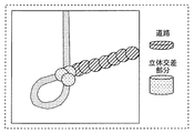
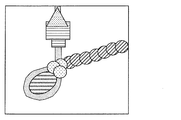
- FIG. 41 is a diagram showing an example of tile shapes according to the sixth embodiment.
- FIG. 42 is a diagram showing an example of tiles and slices according to the sixth embodiment.
- FIG. 43 is a block diagram of a dividing unit according to the sixth embodiment.
- FIG. 44 is a diagram showing an example of a map in which the point cloud data according to the sixth embodiment is viewed from above.
- FIG. 44 is a diagram showing an example of a map in which the point cloud data according to the sixth embodiment is viewed from above.
- FIG. 45 is a diagram showing an example of tile division according to the sixth embodiment.
- FIG. 46 is a diagram showing an example of tile division according to the sixth embodiment.
- FIG. 47 is a diagram showing an example of tile division according to the sixth embodiment.
- FIG. 48 is a diagram showing an example of tile data stored in the server according to the sixth embodiment.
- FIG. 49 is a diagram showing a system regarding tile division according to the sixth embodiment.
- FIG. 50 is a diagram showing an example of slice division according to the sixth embodiment.
- FIG. 51 is a diagram showing an example of the dependency relationship according to the sixth embodiment.
- FIG. 52 is a diagram showing an example of the decoding order of data according to the sixth embodiment.
- FIG. 53 is a diagram showing an example of encoded data of tiles according to the sixth embodiment.
- FIG. 54 is a block diagram of a coupling unit according to the sixth embodiment.
- FIG. 55 is a diagram showing a configuration example of encoded data and NAL units according to the sixth embodiment.
- FIG. 56 is a flowchart of the encoding process according to the sixth embodiment.
- FIG. 57 is a flowchart of the decoding process according to the sixth embodiment.
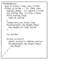
- FIG. 58 is a diagram showing a syntax example of tile additional information according to the sixth embodiment.
- FIG. 59 is a block diagram of an encoding/decoding system according to the sixth embodiment.
- FIG. 60 is a diagram showing a syntax example of slice additional information according to the sixth embodiment.
- FIG. 61 is a flowchart of the encoding process according to the sixth embodiment.
- FIG. 62 is a flowchart of the decoding process according to the sixth embodiment.
- FIG. 63 is a flowchart of the encoding process according to the sixth embodiment.
- FIG. 64 is a flowchart of the decoding process according to the sixth embodiment.
- FIG. 65 is a diagram showing an example of a division method according to the seventh embodiment.
- FIG. 66 is a diagram showing an example of division of the point cloud data according to the seventh embodiment.
- FIG. 67 is a diagram showing a syntax example of tile additional information according to the seventh embodiment.
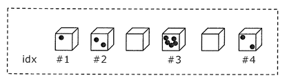
- FIG. 68 is a diagram showing an example of index information according to the seventh embodiment.
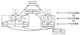
- FIG. 69 is a diagram showing an example of the dependency relationship according to the seventh embodiment.
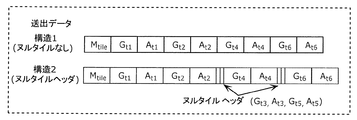
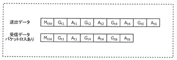
- FIG. 70 is a diagram showing an example of transmission data according to the seventh embodiment.
- FIG. 71 is a diagram showing a configuration example of the NAL unit according to the seventh embodiment.
- FIG. 72 is a diagram showing an example of the dependency relationship according to the seventh embodiment.
- FIG. 73 is a diagram showing an example of the decoding order of data according to the seventh embodiment.
- FIG. 74 is a diagram showing an example of the dependency relationship according to the seventh embodiment.
- FIG. 75 is a diagram showing an example of the decoding order of data according to the seventh embodiment.
- FIG. 76 is a flowchart of the encoding process according to the seventh embodiment.
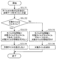
- FIG. 77 is a flowchart of the decoding process according to the seventh embodiment.
- FIG. 78 is a flowchart of the encoding process according to the seventh embodiment.
- FIG. 80 is a diagram showing an example of transmission data and reception data according to the seventh embodiment.
- FIG. 81 is a flowchart of the decoding process according to the seventh embodiment.
- FIG. 82 is a diagram showing an example of transmission data and reception data according to the seventh embodiment.
- FIG. 83 is a flowchart of the decoding process according to the seventh embodiment.
- FIG. 84 is a flowchart of the encoding process according to the seventh embodiment.
- FIG. 85 is a diagram showing an example of index information according to the seventh embodiment.
- FIG. 86 is a diagram showing an example of the dependency relationship according to the seventh embodiment.
- FIG. 87 is a diagram showing an example of transmission data according to the seventh embodiment.
- FIG. 88 is a diagram showing an example of transmission data and reception data according to the seventh embodiment.
- FIG. 89 is a flowchart of the decoding process according to the seventh embodiment.
- FIG. 90 is a flowchart of the encoding process according to the seventh embodiment.
- FIG. 91 is a flowchart of the decoding process according to the seventh embodiment.
- FIG. 92 is a block diagram showing an example of the configuration of the three-dimensional data encoding device according to the eighth embodiment.
- FIG. 93 is a diagram for explaining the outline of the encoding method by the three-dimensional data encoding device according to the eighth embodiment.
- FIG. 94 is a diagram for explaining the first example of the position shift according to the eighth embodiment.
- FIG. 95 is a diagram for explaining the second example of the position shift according to the eighth embodiment.
- FIG. 96 is a flowchart showing an example of the encoding method according to the eighth embodiment.
- FIG. 97 is a flowchart showing an example of the decoding method according to the eighth embodiment.
- FIG. 98 is a diagram for explaining the third example of the position shift according to the eighth embodiment.
- FIG. 99 is a flowchart showing an example of the encoding method according to the eighth embodiment.
- FIG. 100 is a flowchart showing an example of the decoding method according to the eighth embodiment.
- FIG. 101 is a diagram for explaining the fourth example of the position shift according to the eighth embodiment.
- FIG. 102 is a flowchart showing an example of the encoding method according to the eighth embodiment.
- FIG. 103 is a diagram for explaining the fifth example of the position shift according to the eighth embodiment.
- FIG. 104 is a diagram for explaining the encoding method according to the eighth embodiment.
- FIG. 105 is a diagram showing an example of GPS syntax according to the eighth embodiment.
- FIG. 106 is a diagram showing an example of the syntax of the header of the position information according to the eighth embodiment.
- FIG. 107 is a flowchart showing an example of an encoding method for switching the processing according to the eighth embodiment.
- FIG. 108 is a flowchart showing an example of the decoding method for switching the processing according to the eighth embodiment.
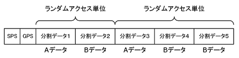
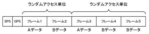
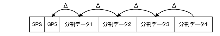
- FIG. 109 is a diagram illustrating an example of a data structure of a bitstream according to Embodiment 8.
- FIG. 110 shows an example in which the divided data of FIG.
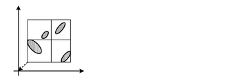
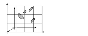
- FIG. 111 is a diagram showing another example of the divided area according to the eighth embodiment.
- FIG. 112 is a diagram showing another example of the divided area according to the eighth embodiment.
- FIG. 113 is a diagram showing another example of the divided area according to the eighth embodiment.
- FIG. 114 is a diagram showing another example of divided areas according to the eighth embodiment.
- FIG. 115 is a diagram showing another example of the data structure according to the eighth embodiment.
- FIG. 116 is a diagram showing another example of the data structure according to the eighth embodiment.
- FIG. 117 is a diagram showing another example of the data structure according to the eighth embodiment.
- FIG. 118 is a diagram showing another example of the data structure according to the eighth embodiment.
- FIG. 119 is a diagram showing another example of the data structure according to the eighth embodiment.
- FIG. 120 is a flowchart of the encoding process according to the eighth embodiment.
- FIG. 121 is a flowchart of the decoding process according to the eighth embodiment.
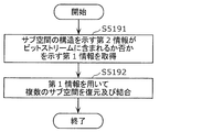
- a three-dimensional data encoding method is a three-dimensional data encoding method for encoding point group data indicating a plurality of three-dimensional positions in a three-dimensional space, wherein the point group data is first
- the point cloud data is divided into a plurality of sub-point cloud data by moving the three-dimensional space into a plurality of sub-spaces by moving by the moving amount, and the point cloud data after moving by the first moving amount.
- the sub point group data For each of the plurality of sub point group data included in, the sub point group data is moved by a second movement amount based on the position of the sub space in which the sub point group data is included, and the plurality of sub points after the movement
- a bitstream is generated by encoding the group data, and the bitstream includes first movement information for calculating the first movement amount and a plurality of the plurality of sub-point group data obtained by moving the plurality of sub-point group data. It includes a plurality of second movement information for calculating each of the two movement amounts.
- the divided sub point cloud data is encoded after being moved, the amount of position information of each sub point cloud data can be reduced and the encoding efficiency can be improved.
- each of the plurality of second movement information includes the number of the plurality of subspaces and a first identification for identifying a corresponding subspace. It may include information.
- the information amount of the second movement information can be reduced and the coding efficiency can be improved.
- the first identification information may be a Morton order corresponding to each of the plurality of subspaces.
- each of the plurality of subspaces is a space obtained by dividing one three-dimensional space using an octree
- the bitstream is obtained by dividing the plurality of subspaces using an octree.
- the second identification information indicating the space and the depth information indicating the depth of the octree may be included.
- the point cloud data in the three-dimensional space is divided using an octree, the amount of position information of each sub point cloud data can be reduced, and the coding efficiency can be improved.
- the division may be performed after moving the point cloud data by the first movement amount.
- a three-dimensional data decoding method uses a plurality of sub point group data obtained by dividing point group data indicating a plurality of three-dimensional positions by dividing a three-dimensional space into a plurality of sub spaces. And a plurality of sub-point cloud data sets, each of which has been moved by a first movement amount and a corresponding second movement amount, first movement information for calculating the first movement amount, and the plurality of sub-points.
- a plurality of second movement information for respectively calculating the plurality of second movement amounts obtained by moving the point cloud data is decoded from the bitstream, and each of the plurality of sub point cloud data is subjected to the first movement.
- the point cloud data may be restored by moving an amount and a moving amount obtained by adding the corresponding second moving amount.
- each of the plurality of second movement information includes the number of the plurality of subspaces and a first identification for identifying a corresponding subspace. It may include information.
- the first identification information may be a Morton order corresponding to each of the plurality of subspaces.
- each of the plurality of subspaces is a space obtained by dividing one three-dimensional space using an octree
- the bitstream is obtained by dividing the plurality of subspaces using an octree.
- the second identification information indicating the space and the depth information indicating the depth of the octree may be included.
- a three-dimensional data encoding device is a three-dimensional data encoding device that encodes point group data indicating a plurality of three-dimensional positions in a three-dimensional space, including a processor, a memory, and And the processor uses the memory to move the point cloud data by a first movement amount and divide the three-dimensional space into a plurality of sub-spaces, thereby converting the point cloud data into a plurality of sub-points.
- a bitstream is generated by moving the sub-point cloud data by an amount of movement and encoding the plurality of sub-point cloud data after movement, and the bitstream is a first bit for calculating the first amount of movement.
- the divided sub point cloud data is encoded after being moved, the amount of position information of each sub point cloud data can be reduced and the encoding efficiency can be improved.
- a three-dimensional data decoding device includes a processor and a memory, and the processor uses the memory to divide a three-dimensional space into a plurality of sub-spaces to thereby form a plurality of cubics.
- a plurality of sub point cloud data obtained by dividing the point cloud data indicating the original position, each of which is moved by a first movement amount and a corresponding second movement amount; From the bitstream, first movement information for calculating one movement amount and a plurality of second movement information for calculating each of the plurality of second movement amounts obtained by moving the plurality of sub-point cloud data are provided.
- the point cloud data may be restored by decoding and moving each of the plurality of sub-point group data by the moving amount obtained by adding the first moving amount and the corresponding second moving amount.
- a recording medium such as a system, a method, an integrated circuit, a computer program or a computer-readable CD-ROM, and the system, the method, the integrated circuit, the computer program. And may be realized by any combination of recording media.
- a three-dimensional data encoding method and a three-dimensional data encoding device for providing a function of transmitting and receiving necessary information according to the application in the encoded data of the three-dimensional point cloud, and the code 3D data decoding method and 3D data decoding device for decoding encoded data, 3D data multiplexing method for multiplexing the encoded data, and 3D data transmission method for transmitting the encoded data To do.
- the first encoding method and the second encoding method are being studied as the encoding method (encoding method) of the point cloud data.
- the configuration of the encoded data and the encoded data system The method of storing in the format is not defined, and there is a problem that MUX processing (multiplexing) in the encoding unit, or transmission or storage cannot be performed as it is.
- PCC Point Cloud Compression
- FIG. 1 is a diagram showing a configuration example of a three-dimensional data encoding/decoding system according to the present embodiment.
- the 3D data encoding/decoding system includes a 3D data encoding system 4601, a 3D data decoding system 4602, a sensor terminal 4603, and an external connection unit 4604.
- the three-dimensional data encoding system 4601 generates encoded data or multiplexed data by encoding the point cloud data that is three-dimensional data.
- the three-dimensional data encoding system 4601 may be a three-dimensional data encoding device realized by a single device or may be a system realized by a plurality of devices.
- the three-dimensional data encoding device may include a part of the plurality of processing units included in the three-dimensional data encoding system 4601.
- the three-dimensional data encoding system 4601 includes a point cloud data generation system 4611, a presentation unit 4612, an encoding unit 4613, a multiplexing unit 4614, an input/output unit 4615, and a control unit 4616.
- the point cloud data generation system 4611 includes a sensor information acquisition unit 4617 and a point cloud data generation unit 4618.
- the sensor information acquisition unit 4617 acquires sensor information from the sensor terminal 4603 and outputs the sensor information to the point cloud data generation unit 4618.
- the point cloud data generation unit 4618 generates point cloud data from the sensor information and outputs the point cloud data to the encoding unit 4613.
- the presentation unit 4612 presents sensor information or point cloud data to the user. For example, the presentation unit 4612 displays information or an image based on sensor information or point cloud data.
- the encoding unit 4613 encodes (compresses) the point cloud data, and outputs the obtained encoded data, the control information obtained in the encoding process, and other additional information to the multiplexing unit 4614.
- the additional information includes, for example, sensor information.
- the multiplexing unit 4614 generates multiplexed data by multiplexing the encoded data input from the encoding unit 4613, the control information, and the additional information.
- the format of the multiplexed data is, for example, a file format for storage or a packet format for transmission.
- the input/output unit 4615 (eg, communication unit or interface) outputs the multiplexed data to the outside.
- the multiplexed data is stored in a storage unit such as an internal memory.
- the control unit 4616 (or the application execution unit) controls each processing unit. That is, the control unit 4616 performs control such as encoding and multiplexing.
- the sensor information may be input to the encoding unit 4613 or the multiplexing unit 4614.
- the input/output unit 4615 may output the point cloud data or the encoded data as it is to the outside.
- the transmission signal (multiplexed data) output from the three-dimensional data encoding system 4601 is input to the three-dimensional data decoding system 4602 via the external connection unit 4604.
- the 3D data decoding system 4602 generates point cloud data, which is 3D data, by decoding encoded data or multiplexed data.
- the three-dimensional data decoding system 4602 may be a three-dimensional data decoding device realized by a single device or may be a system realized by a plurality of devices.
- the three-dimensional data decoding device may include a part of the plurality of processing units included in the three-dimensional data decoding system 4602.
- the three-dimensional data decoding system 4602 includes a sensor information acquisition unit 4621, an input/output unit 4622, a demultiplexing unit 4623, a decoding unit 4624, a presentation unit 4625, a user interface 4626, and a control unit 4627.
- the sensor information acquisition unit 4621 acquires sensor information from the sensor terminal 4603.
- the input/output unit 4622 acquires the transmission signal, decodes the multiplexed data (file format or packet) from the transmission signal, and outputs the multiplexed data to the demultiplexing unit 4623.
- the demultiplexing unit 4623 acquires the encoded data, the control information and the additional information from the multiplexed data, and outputs the encoded data, the control information and the additional information to the decoding unit 4624.
- the decoding unit 4624 reconstructs the point cloud data by decoding the encoded data.
- the presentation unit 4625 presents the point cloud data to the user. For example, the presentation unit 4625 displays information or an image based on the point cloud data.
- the user interface 4626 acquires an instruction based on a user operation.
- the control unit 4627 (or the application execution unit) controls each processing unit. That is, the control unit 4627 performs control such as demultiplexing, decoding and presentation.
- the input/output unit 4622 may directly acquire the point cloud data or the encoded data from the outside.
- the presentation unit 4625 may acquire additional information such as sensor information and present the information based on the additional information. Further, the presentation unit 4625 may perform the presentation based on the user instruction acquired by the user interface 4626.
- the sensor terminal 4603 generates sensor information which is information obtained by the sensor.
- the sensor terminal 4603 is a terminal equipped with a sensor or a camera, and includes, for example, a moving object such as an automobile, a flying object such as an airplane, a mobile terminal, or a camera.
- the sensor information that can be acquired by the sensor terminal 4603 is, for example, (1) the distance between the sensor terminal 4603 and an object, or the reflectance of the object, which is obtained from LIDAR, a millimeter wave radar, or an infrared sensor; Is the distance between the camera and the object obtained from the monocular camera image or the stereo camera image, the reflectance of the object, or the like.
- the sensor information may include the orientation, orientation, gyro (angular velocity), position (GPS information or altitude), velocity, acceleration, etc. of the sensor.
- the sensor information may include temperature, atmospheric pressure, humidity, magnetism, or the like.
- the external connection unit 4604 is realized by an integrated circuit (LSI or IC), an external storage unit, communication with a cloud server via the Internet, broadcasting, or the like.
- LSI integrated circuit
- IC integrated circuit
- FIG. 2 is a diagram showing the structure of point cloud data.
- FIG. 3 is a diagram showing a configuration example of a data file in which information on point cloud data is described.
- ⁇ Point cloud data includes data of multiple points.
- the data of each point includes position information (three-dimensional coordinates) and attribute information for the position information.
- a set of multiple points is called a point cloud.
- the point cloud indicates a three-dimensional shape of an object (object).
- Positional information such as three-dimensional coordinates may be called geometry.
- the data of each point may include attribute information (attribute) of a plurality of attribute types.
- the attribute type is, for example, color or reflectance.
- One piece of attribute information may be associated with one piece of location information, or one piece of location information may be associated with pieces of attribute information having a plurality of different attribute types. Further, a plurality of pieces of attribute information of the same attribute type may be associated with one piece of position information.
- the configuration example of the data file shown in FIG. 3 is an example of the case where the position information and the attribute information have a one-to-one correspondence, and shows the position information and the attribute information of N points forming the point cloud data. There is.
- the position information is, for example, information on three axes of x, y, and z.
- the attribute information is, for example, RGB color information.
- a typical file is a ply file.
- FIG. 4 is a diagram showing types of point cloud data. As shown in FIG. 4, the point cloud data includes static objects and dynamic objects.
- Statistic object is 3D point cloud data at any time (some time).
- a dynamic object is three-dimensional point cloud data that changes with time.
- the three-dimensional point cloud data at a certain time will be referred to as a PCC frame or a frame.
- the object may be a point cloud whose area is limited to some extent, such as normal video data, or a large-scale point cloud whose area is not limited, such as map information.
- point cloud data of various densities there are point cloud data of various densities, and sparse point cloud data and dense point cloud data may exist.
- the sensor information is acquired by various methods such as a distance sensor such as a LIDAR or a range finder, a stereo camera, or a combination of a plurality of monocular cameras.
- the point cloud data generation unit 4618 generates point cloud data based on the sensor information obtained by the sensor information acquisition unit 4617.
- the point cloud data generation unit 4618 generates position information as point cloud data and adds attribute information for the position information to the position information.
- the point cloud data generation unit 4618 may process the point cloud data when generating the position information or adding the attribute information. For example, the point cloud data generation unit 4618 may reduce the data amount by deleting the point cloud whose positions overlap. Further, the point cloud data generation unit 4618 may convert the position information (position shift, rotation, normalization, etc.), or may render the attribute information.
- point cloud data generation system 4611 is included in the three-dimensional data encoding system 4601 in FIG. 1, it may be independently provided outside the three-dimensional data encoding system 4601.
- the coding unit 4613 generates coded data by coding the point cloud data based on a coding method defined in advance.
- a coding method There are the following two types of encoding methods.
- the first is a coding method using position information, and this coding method will be hereinafter referred to as a first coding method.
- the second is a coding method using a video codec, and this coding method is hereinafter referred to as a second coding method.
- the decoding unit 4624 decodes the point cloud data by decoding the coded data based on the coding method defined in advance.
- the multiplexing unit 4614 generates multiplexed data by multiplexing encoded data using an existing multiplexing method.
- the generated multiplexed data is transmitted or stored.
- the multiplexing unit 4614 multiplexes other media such as video, audio, subtitles, applications, files, or reference time information, in addition to the PCC encoded data. Also, the multiplexing unit 4614 may further multiplex attribute information related to the sensor information or the point cloud data.
- ISOBMFF ISOBMFF-based transmission methods such as MPEG-DASH, MMT, MPEG-2 TS Systems, and RMP.
- the demultiplexing unit 4623 extracts PCC encoded data, other media, time information, etc. from the multiplexed data.
- the input/output unit 4615 transmits the multiplexed data using a method suitable for the medium to be transmitted or the medium to be stored, such as broadcasting or communication.
- the input/output unit 4615 may communicate with another device via the Internet, or may communicate with a storage unit such as a cloud server.
- http http, ftp, TCP, UDP, etc. are used.
- a PULL type communication method may be used, or a PUSH type communication method may be used.
- Either wired transmission or wireless transmission may be used.
- Ethernet registered trademark
- USB registered trademark
- RS-232C HDMI
- coaxial cable or the like is used.
- wireless transmission wireless LAN, Wi-Fi (registered trademark), Bluetooth (registered trademark), millimeter wave, or the like is used.
- DVB-T2, DVB-S2, DVB-C2, ATSC3.0, or ISDB-S3 is used as the broadcasting system.
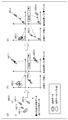
- FIG. 5 is a diagram showing a configuration of a first encoding unit 4630 that is an example of an encoding unit 4613 that performs encoding of the first encoding method.
- FIG. 6 is a block diagram of the first encoding unit 4630.
- the first coding unit 4630 generates coded data (coded stream) by coding the point cloud data by the first coding method.
- the first encoding unit 4630 includes a position information encoding unit 4631, an attribute information encoding unit 4632, an additional information encoding unit 4633, and a multiplexing unit 4634.
- the first encoding unit 4630 has a feature of performing encoding while being aware of the three-dimensional structure.
- the first encoding unit 4630 has a characteristic that the attribute information encoding unit 4632 performs encoding using the information obtained from the position information encoding unit 4631.
- the first encoding method is also called GPCC (Geometry based PCC).
- the point cloud data is PCC point cloud data such as a PLY file or PCC point cloud data generated from sensor information, and includes position information (Position), attribute information (Attribute), and other additional information (MetaData). including.
- the position information is input to the position information encoding unit 4631, the attribute information is input to the attribute information encoding unit 4632, and the additional information is input to the additional information encoding unit 4633.
- the position information encoding unit 4631 generates encoded position information (Compressed Geometry) that is encoded data by encoding the position information.
- the position information encoding unit 4631 encodes position information using an N-ary tree structure such as an octree. Specifically, in the octree, the target space is divided into eight nodes (subspaces), and 8-bit information (occupancy code) indicating whether or not each node includes a point cloud is generated. .. The node including the point cloud is further divided into eight nodes, and 8-bit information indicating whether or not each of the eight nodes includes the point cloud is generated. This process is repeated until the number of points included in a predetermined hierarchy or node is equal to or less than the threshold value.
- the attribute information encoding unit 4632 generates encoded attribute information (Compressed Attribute) that is encoded data by performing encoding using the configuration information generated by the position information encoding unit 4631. For example, the attribute information encoding unit 4632 determines a reference point (reference node) to be referred to in encoding the target point (target node) to be processed, based on the octree structure generated by the position information encoding unit 4631. To do. For example, the attribute information encoding unit 4632 refers to a peripheral node or an adjacent node whose parent node in the octree is the same as the target node. The method of determining the reference relationship is not limited to this.
- the attribute information encoding process may include at least one of a quantization process, a prediction process, and an arithmetic encoding process.
- the reference refers to using the reference node to calculate the predicted value of the attribute information, or the state of the reference node in determining the encoding parameter (for example, occupancy indicating whether the reference node includes a point cloud or not). Information).
- the encoding parameter is a quantization parameter in quantization processing, a context in arithmetic encoding, or the like.
- the additional information encoding unit 4633 generates encoded additional information (Compressed MetaData) that is encoded data by encoding compressible data in the additional information.
- compressed MetaData encoded additional information
- the multiplexing unit 4634 multiplexes the coding position information, the coding attribute information, the coding additional information, and other additional information to generate a coded stream (Compressed Stream) that is coded data.
- the generated coded stream is output to the processing unit of the system layer (not shown).
- FIG. 7 is a diagram showing the configuration of the first decoding unit 4640.
- FIG. 8 is a block diagram of the first decoding unit 4640.
- the first decoding unit 4640 generates point cloud data by decoding the coded data (coded stream) coded by the first coding method by the first coding method.
- the first decoding unit 4640 includes a demultiplexing unit 4641, a position information decoding unit 4642, an attribute information decoding unit 4643, and an additional information decoding unit 4644.
- An encoded stream (Compressed Stream) that is encoded data is input to the first decoding unit 4640 from a processing unit of a system layer (not shown).
- the demultiplexing unit 4641 separates encoded position information (Compressed Geometry), encoded attribute information (Compressed Attribute), encoded additional information (Compressed MetaData), and other additional information from the encoded data.
- the position information decoding unit 4642 generates position information by decoding the coded position information. For example, the position information decoding unit 4642 restores the position information of the point group represented by the three-dimensional coordinates from the encoded position information represented by the N-tree structure such as an octree.
- the attribute information decoding unit 4643 decodes the encoded attribute information based on the configuration information generated by the position information decoding unit 4642. For example, the attribute information decoding unit 4643 determines the reference point (reference node) to be referred in decoding the target point (target node) to be processed, based on the octree structure obtained by the position information decoding unit 4642. For example, the attribute information decoding unit 4643 refers to, among the peripheral nodes or adjacent nodes, the node whose parent node in the octree is the same as the target node. The method of determining the reference relationship is not limited to this.
- the attribute information decoding process may include at least one of a dequantization process, a prediction process, and an arithmetic decoding process.
- the reference refers to using the reference node to calculate the predicted value of the attribute information, or the state of the reference node in determining the decoding parameter (for example, occupancy information indicating whether the reference node includes a point cloud or not). ) Is used.
- the decoding parameter is a quantization parameter in inverse quantization processing, a context in arithmetic decoding, or the like.
- the additional information decoding unit 4644 generates additional information by decoding the encoded additional information. Also, the first decoding unit 4640 uses the additional information necessary for the decoding process of the position information and the attribute information at the time of decoding, and outputs the additional information necessary for the application to the outside.
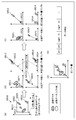
- FIG. 9 is a diagram showing the configuration of the second encoding unit 4650.
- FIG. 10 is a block diagram of the second encoding unit 4650.
- the second encoding unit 4650 generates encoded data (encoded stream) by encoding the point cloud data by the second encoding method.
- the second encoding unit 4650 includes an additional information generating unit 4651, a position image generating unit 4652, an attribute image generating unit 4653, a video encoding unit 4654, an additional information encoding unit 4655, and a multiplexing unit 4656. Including and
- the second encoding unit 4650 generates the position image and the attribute image by projecting the three-dimensional structure on the two-dimensional image, and encodes the generated position image and the attribute image using the existing video encoding method. It has the feature.
- the second encoding method is also called VPCC (Video based PCC).
- the point cloud data is PCC point cloud data such as a PLY file, or PCC point cloud data generated from sensor information, and includes position information (Position), attribute information (Attribute), and other additional information MetaData). Including.
- the additional information generation unit 4651 generates map information of a plurality of two-dimensional images by projecting the three-dimensional structure on a two-dimensional image.
- the position image generation unit 4652 generates a position image (Geometry Image) based on the position information and the map information generated by the additional information generation unit 4651.
- This position image is, for example, a distance image in which a distance (Depth) is shown as a pixel value.
- this range image may be an image in which a plurality of point groups are viewed from one viewpoint (an image in which a plurality of point groups are projected on one two-dimensional plane), or a plurality of point groups from a plurality of viewpoints. It may be a plurality of images viewed, or may be a single image obtained by integrating these plurality of images.
- the attribute image generating unit 4653 generates an attribute image based on the attribute information and the map information generated by the additional information generating unit 4651.
- This attribute image is, for example, an image in which attribute information (for example, color (RGB)) is shown as a pixel value.
- RGB color
- this image may be an image in which a plurality of point clouds are viewed from one viewpoint (an image obtained by projecting a plurality of point groups on one two-dimensional plane), or a plurality of point groups may be viewed from a plurality of viewpoints. It may be a plurality of viewed images or one image obtained by integrating these plurality of images.
- the video encoding unit 4654 encodes the position image and the attribute image by using the video encoding method, so that the encoded position image (Compressed Geometry Image) and the encoded attribute image (Compressed Attribute Image) are encoded data. ) Is generated.
- Any known encoding method may be used as the video encoding method.
- the video encoding method is AVC, HEVC, or the like.
- the additional information encoding unit 4655 generates encoded additional information (Compressed MetaData) by encoding the additional information included in the point cloud data, the map information, and the like.
- the multiplexing unit 4656 generates a coded stream (Compressed Stream) that is coded data by multiplexing the coded position image, the coded attribute image, the coded additional information, and other additional information.
- the generated coded stream is output to the processing unit of the system layer (not shown).
- FIG. 11 is a diagram showing the configuration of the second decoding unit 4660.
- FIG. 12 is a block diagram of the second decoding unit 4660.
- the second decoding unit 4660 generates point cloud data by decoding the coded data (coded stream) coded by the second coding method by the second coding method.
- the second decoding unit 4660 includes a demultiplexing unit 4661, a video decoding unit 4662, an additional information decoding unit 4663, a position information generation unit 4664, and an attribute information generation unit 4665.
- An encoded stream (Compressed Stream) that is encoded data is input to the second decoding unit 4660 from a processing unit of a system layer (not shown).
- the demultiplexing unit 4661 separates the encoded position image (Compressed Geometry Image), the encoded attribute image (Compressed Attribute Image), the encoded additional information (Compressed MetaData), and other additional information from the encoded data. ..
- the video decoding unit 4662 generates the position image and the attribute image by decoding the encoded position image and the encoded attribute image using the video encoding method.
- Any known encoding method may be used as the video encoding method.
- the video encoding method is AVC, HEVC, or the like.
- the additional information decoding unit 4663 generates additional information including map information by decoding the encoded additional information.
- the position information generation unit 4664 generates position information using the position image and map information.
- the attribute information generation unit 4665 generates attribute information using the attribute image and map information.
- the second decryption unit 4660 uses the additional information required for the decryption at the time of decryption and outputs the additional information required for the application to the outside.
- FIG. 13 is a diagram showing a protocol stack related to PCC encoded data.
- FIG. 13 shows an example in which data of another medium such as video (for example, HEVC) or audio is multiplexed with PCC encoded data and transmitted or stored.
- video for example, HEVC
- audio is multiplexed with PCC encoded data and transmitted or stored.
- the multiplexing method and file format have the function to multiplex various encoded data and transmit or store them.
- the coded data In order to transmit or store the coded data, the coded data must be converted into a multiplexing format.
- HEVC defines a technique of storing encoded data in a data structure called a NAL unit and storing the NAL unit in ISOBMFF.
- the first encoding method (Codec1) and the second encoding method (Codec2) are being studied as the encoding method of the point cloud data, but the configuration of the encoded data and the encoded data are The method of storing in the system format is not defined, and there is a problem that MUX processing (multiplexing), transmission, and storage in the encoding unit cannot be performed as they are.
- ISOBMFF ISO based media file format
- ISOBMFF ISO based media file format
- ISOBMFF is a standard that does not depend on media, which defines a format in which various media such as video, audio, and text can be multiplexed and stored.
- the basic unit in ISOBMFF is a box.
- a box is composed of type, length, and data, and a set is a file in which boxes of various types are combined.
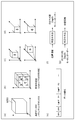
- FIG. 14 is a diagram showing a basic structure (file) of ISOBMFF.
- the ISOBMFF file mainly includes boxes such as ftyp that indicates the brand of the file by 4CC (4 character code), moov that stores metadata such as control information, and mdat that stores data.
- the storage method for each media in the ISOBMFF file is separately specified.
- the storage method for AVC video and HEVC video is specified in ISO/IEC 14496-15.
- ISO/IEC 14496-15 it is conceivable that the function of ISOBMFF is expanded and used to store or transmit the PCC encoded data, but there is no provision yet to store the PCC encoded data in the ISOBMFF file. Therefore, in this embodiment, a method of storing PCC encoded data in an ISOBMFF file will be described.
- FIG. 15 is a diagram showing a protocol stack when a NAL unit common to PCC codecs is stored in an ISOBMFF file.
- the NAL unit common to the PCC codec is stored in the ISOBMFF file.
- the NAL unit is common to the PCC codecs, but since multiple PCC codecs are stored in the NAL unit, it is desirable to specify the storage method (Carryage of Codec1, Carriage of Codec2) according to each codec.
- FIG. 16 is a diagram showing an example in which a common PCC NAL unit is stored in an ISOBMFF file of the storage method (Carriage of Codec 1) of codec 1.
- FIG. 17 is a diagram showing an example in which a common PCC NAL unit is stored in an ISOBMFF file according to the storage method (Carriage of Codec 2) of codec 2.
- ftyp is important information for identifying the file format, and a different identifier is defined for each codec for ftyp.
- pcc1 indicates that PCC codec 1 (first encoding method) is used.
- pcc2 indicates that the PCC codec 2 (second encoding method) is used. That is, pcc1 and pcc2 indicate that the data is PCC (coded data of three-dimensional data (point cloud data)), and also indicate the PCC codec (first coding method and second coding method). ..
- the multiplexing unit stores the NAL unit in, for example, moov or mdat in a predetermined method.
- the multiplexing unit stores the NAL unit in, for example, moov or mdat in a predetermined method.
- the multiplexing unit may store the NAL unit size in the NAL unit as in HEVC.
- the PCC encoded data is encoded by the first encoding method or encoded by the second encoding method. It is possible to determine whether or not it has been converted. Further, as described above, it is encoded by both encoding methods by determining whether the PCC encoded data is encoded by the first encoding method or the second encoding method. It is possible to extract the encoded data encoded by either one of the encoding methods from the data in which the encoded data is mixed. This makes it possible to suppress the amount of data to be transmitted when transmitting encoded data. Further, according to this storage method, a common data format can be used between the first encoding method and the second encoding method without setting different data (file) formats.
- the multiplexing unit may store the NAL unit from which pcc_nal_unit_type is deleted in the ISOBMFF file.
- the multiplexing unit included in the three-dimensional data encoding system (three-dimensional data encoding device) according to the present embodiment and the three-dimensional data decoding system (three-dimensional data decoding device) according to the present embodiment will be described.
- the configuration and operation of the provided demultiplexer will be described.
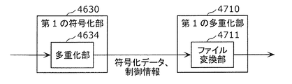
- FIG. 18 is a diagram showing the configuration of the first multiplexing unit 4710.
- the first multiplexing unit 4710 generates the multiplexed data (file) by storing the encoded data and control information (NAL unit) generated by the first encoding unit 4630 in the ISOBMFF file.
- the portion 4711 is provided.
- the first multiplexing unit 4710 is included in, for example, the multiplexing unit 4614 shown in FIG.
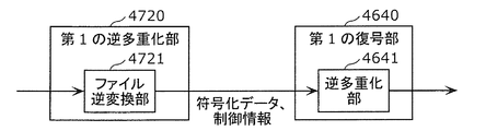
- FIG. 19 is a diagram showing the configuration of the first demultiplexing unit 4720.
- the first demultiplexing unit 4720 acquires encoded data and control information (NAL unit) from the multiplexed data (file), and outputs the obtained encoded data and control information to the first decoding unit 4640.
- the inverse conversion unit 4721 is provided.
- the first demultiplexing unit 4720 is included in the demultiplexing unit 4623 shown in FIG. 1, for example.
- FIG. 20 is a diagram showing the configuration of the second multiplexing unit 4730.
- the second multiplexing unit 4730 stores the encoded data and the control information (NAL unit) generated by the second encoding unit 4650 in the ISOBMFF file to generate the multiplexed data (file) File conversion
- the portion 4731 is provided.
- the second multiplexing unit 4730 is included in the multiplexing unit 4614 shown in FIG. 1, for example.
- FIG. 21 is a diagram showing the configuration of the second demultiplexing unit 4740.
- the second demultiplexing unit 4740 acquires encoded data and control information (NAL unit) from the multiplexed data (file), and outputs the obtained encoded data and control information to the second decoding unit 4660.
- the inverse conversion unit 4741 is provided.
- the second demultiplexing unit 4740 is included in the demultiplexing unit 4623 shown in FIG. 1, for example.
- FIG. 22 is a flowchart of the multiplexing process performed by the first multiplexing unit 4710.
- the first multiplexing unit 4710 analyzes the pcc_codec_type included in the NAL unit header to determine whether the codec used is the first coding method or the second coding method. A determination is made (S4701).
- the first multiplexing unit 4710 does not process the NAL unit (S4703).
- the first multiplexing unit 4710 when pcc_codec_type indicates the second encoding method (first encoding method in S4702), the first multiplexing unit 4710 describes pcc1 in ftype (S4704). That is, the first multiplexing unit 4710 describes in ftyp the information indicating that the data encoded by the first encoding method is stored in the file.
- the first multiplexing unit 4710 analyzes pcc_nal_unit_type included in the NAL unit header, and stores the data in a box (moov or mdat etc.) by a predetermined method according to the data type indicated by pcc_nal_unit_type (S4705). ). Then, the first multiplexing unit 4710 creates an ISOBMFF file including the ftyp and the box (S4706).
- FIG. 23 is a flowchart of the multiplexing process performed by the second multiplexing unit 4730.
- the second multiplexing unit 4730 analyzes the pcc_codec_type included in the NAL unit header to determine whether the codec used is the first coding method or the second coding method. A determination is made (S4711).
- the second multiplexing unit 4730 If pcc_unit_type indicates the second encoding method (second encoding method in S4712), the second multiplexing unit 4730 describes pcc2 in ftype (S4713). That is, the second multiplexing unit 4730 describes in ftyp the information indicating that the data encoded by the second encoding method is stored in the file.
- the second multiplexing unit 4730 analyzes pcc_nal_unit_type included in the NAL unit header, and stores the data in a box (moov or mdat etc.) by a predetermined method according to the data type indicated by pcc_nal_unit_type (S4714). ). Then, the second multiplexing unit 4730 creates an ISOBMFF file including the ftyp and the box (S4715).
- the second multiplexing unit 4730 does not process the NAL unit (S4716).
- the above process shows an example in which PCC data is encoded by either the first encoding method or the second encoding method.
- the first multiplexing unit 4710 and the second multiplexing unit 4730 store a desired NAL unit in a file by identifying the codec type of the NAL unit.
- the PCC codec identification information is included in addition to the NAL unit header, the first multiplexing unit 4710 and the second multiplexing unit 4730 are included in other than the NAL unit header in steps S4701 and S4711.
- the identification information of the PCC codec may be used to identify the codec type (first encoding method or second encoding method).
- the first multiplexing unit 4710 and the second multiplexing unit 4730 may delete the pcc_nal_unit_type from the NAL unit header when storing the data in the file in steps S4706 and S4714, and then store the data in the file. Good.
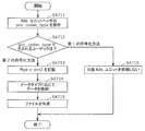
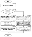
- FIG. 24 is a flowchart showing processing by the first demultiplexing unit 4720 and the first decoding unit 4640.
- the first demultiplexing unit 4720 analyzes ftyp included in the ISOBMFF file (S4721).
- the codec indicated by ftyp is the second encoding method (pcc2) (second encoding method in S4722)
- the first demultiplexing unit 4720 determines that the data included in the payload of the NAL unit is the second. It is determined that the data is coded by the coding method of (S4723).
- the first demultiplexing unit 4720 also transfers the result of the determination to the first decoding unit 4640.
- the first decoding unit 4640 does not process the NAL unit (S4724).
- the first demultiplexing unit 4720 detects that the data included in the payload of the NAL unit is It is determined that the data is coded by the first coding method (S4725). The first demultiplexing unit 4720 also transfers the result of the determination to the first decoding unit 4640.
- the first decoding unit 4640 identifies the data as pcc_nal_unit_type included in the NAL unit header being the identifier of the NAL unit for the first encoding method (S4726). Then, the first decoding unit 4640 decodes the PCC data using the decoding process of the first coding method (S4727).
- FIG. 25 is a flowchart showing the processing by the second demultiplexing unit 4740 and the second decoding unit 4660.
- the second demultiplexing unit 4740 analyzes the ftyp included in the ISOBMFF file (S4731).
- the codec indicated by ftyp is the second coding method (pcc2) (the second coding method in S4732)
- the second demultiplexing unit 4740 determines that the data included in the payload of the NAL unit is the second. It is determined that the data is encoded by the encoding method of (S4733).
- the second demultiplexing unit 4740 also transmits the result of the determination to the second decoding unit 4660.
- the second decoding unit 4660 identifies the data as the pcc_nal_unit_type included in the NAL unit header being the identifier of the NAL unit for the second encoding method (S4734). Then, second decoding section 4660 decodes the PCC data using the decoding process of the second encoding method (S4735).
- the second demultiplexing unit 4740 determines that the data included in the payload of the NAL unit is It is determined that the data is coded by the first coding method (S4736). The second demultiplexing unit 4740 also transmits the result of the determination to the second decoding unit 4660. The second decoding unit 4660 does not process the NAL unit (S4737).
- the codec type can be identified at an early stage.
- a desired NAL unit can be input to the first decoding unit 4640 or the second decoding unit 4660 to remove unnecessary NAL units.
- the first decoding unit 4640 or the second decoding unit 4660 may not need the process of analyzing the codec identification information.
- the first decoding unit 4640 or the second decoding unit 4660 may refer to the NAL unit type again to perform a process of analyzing the codec identification information.
- NAL unit may be assigned pcc_nal_unit_type and then output to the first decoding unit 4640 or the second decoding unit 4660.
- FIG. 26 is a diagram showing configurations of encoding section 4670 and third multiplexing section 4750 according to the present embodiment.
- the encoding unit 4670 encodes the point cloud data by using one or both of the first encoding method and the second encoding method.
- the coding unit 4670 may switch the coding method (first coding method and second coding method) in units of point cloud data or in units of frames.
- the encoding unit 4670 may switch the encoding method in units that can be encoded.
- the encoding unit 4670 generates encoded data (encoded stream) including identification information of the PCC codec.
- the third multiplexing unit 4750 includes a file conversion unit 4751.
- the file conversion unit 4751 converts the NAL unit output from the encoding unit 4670 into a PCC data file.
- the file conversion unit 4751 analyzes the codec identification information included in the NAL unit header, and determines whether the PCC encoded data is data encoded by the first encoding method or encoded by the second encoding method. It is determined whether the data is encoded data or data encoded by both methods.
- the file conversion unit 4751 describes the brand name that can identify the codec in the ftyp. For example, in the case of indicating that the encoding has been performed by both methods, pccc3 is described in ftyp.
- the file conversion unit 4751 may determine the PCC codec (encoding method) using the identification information. ..
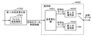
- FIG. 27 is a diagram showing configurations of the third demultiplexing section 4760 and the decoding section 4680 according to the present embodiment.
- the third demultiplexing unit 4760 includes a file deconversion unit 4761.
- the file inverse conversion unit 4761 analyzes the ftyp included in the file, and determines whether the PCC encoded data is the data encoded by the first encoding method or the data encoded by the second encoding method. Or the data is encoded by both methods.
- the data is input to the corresponding decoding unit of the first decoding unit 4640 and the second decoding unit 4660, and the other decoding is performed. No data is entered in the department.
- the PCC encoded data is encoded by both encoding methods, the data is input to the decoding unit 4680 corresponding to both types.
- the decoding unit 4680 decodes the PCC encoded data using either one or both of the first encoding method and the second encoding method.
- FIG. 28 is a flowchart showing processing by the third multiplexing unit 4750 according to this embodiment.
- the third multiplexing unit 4750 analyzes the pcc_codec_type included in the NAL unit header to determine whether the codec used is the first coding method or the second coding method. It is determined whether it is both the first encoding method and the second encoding method (S4741).
- the third multiplexing unit 4750 describes pcc2 in ftyp (S4744). That is, the third multiplexing unit 4750 describes, in ftyp, information indicating that the data encoded by the second encoding method is stored in the file.
- the third multiplexing unit 4750 analyzes pcc_nal_unit_type included in the NAL unit header, and stores the data in a box (moov or mdat etc.) in a predetermined method according to the data type indicated by pcc_unit_type (S4745). ). Then, the third multiplexing unit 4750 creates an ISOBMFF file including the ftyp and the box (S4746).
- the third multiplexing unit 4750 describes pcc1 in ftyp (S4747). That is, the third multiplexing unit 4750 describes, in ftyp, information indicating that the data encoded by the first encoding method is stored in the file.
- the third multiplexing unit 4750 analyzes pcc_nal_unit_type included in the NAL unit header, and stores the data in a box (moov or mdat etc.) by a predetermined method according to the data type indicated by pcc_unit_type (S4748). ). Then, the third multiplexing unit 4750 creates an ISOBMFF file including the ftyp and the box (S4746).
- the third multiplexing unit 4750 describes pcc3 in ftyp ( S4749). That is, the third multiplexing unit 4750 describes in ftyp the information indicating that the data encoded by both encoding methods is stored in the file.
- the third multiplexing unit 4750 analyzes pcc_nal_unit_type included in the NAL unit header, and stores the data in a box (moov or mdat etc.) in a predetermined method according to the data type indicated by pcc_unit_type (S4750). ). Then, the third multiplexing unit 4750 creates an ISOBMFF file including the ftyp and the box (S4746).
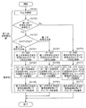
- FIG. 29 is a flowchart showing processing by the third demultiplexing unit 4760 and the decoding unit 4680.
- the third demultiplexing unit 4760 analyzes ftyp included in the ISOBMFF file (S4761).
- the codec indicated by ftyp is the second encoding method (pcc2) (Yes in S4762 and the second encoding method in S4763)
- the third demultiplexing unit 4760 is included in the payload of the NAL unit. It is determined that the data to be encoded is the data encoded by the second encoding method (S4764).
- the third demultiplexing unit 4760 transmits the result of the determination to the decoding unit 4680.
- the decoding unit 4680 identifies the data as pcc_nal_unit_type included in the NAL unit header being the identifier of the NAL unit for the second encoding method (S4765). Then, the decoding unit 4680 decodes the PCC data using the decoding process of the second coding method (S4766).
- the third demultiplexing unit 4760 causes the NAL unit payload to be transmitted. It is determined that the data included in is the data encoded by the first encoding method (S4767). Also, the third demultiplexing unit 4760 transmits the result of the determination to the decoding unit 4680.
- the decoding unit 4680 identifies the data as the pcc_nal_unit_type included in the NAL unit header being the identifier of the NAL unit for the first encoding method (S4768). Then, the decoding unit 4680 decodes the PCC data using the decoding process of the first encoding method (S4769).
- the third demultiplexing unit 4760 determines that the data included in the payload of the NAL unit is the first one. It is determined that the data is coded by both the coding method of 1 and the second coding method (S4770). Also, the third demultiplexing unit 4760 transmits the result of the determination to the decoding unit 4680.
- the decryption unit 4680 identifies the data as the pcc_nal_unit_type included in the NAL unit header being the identifier of the NAL unit for the codec described in the pcc_codec_type (S4771). Then, the decoding unit 4680 decodes the PCC data using the decoding processing of both encoding methods (S4772). That is, the decoding unit 4680 decodes the data encoded by the first encoding method using the decoding process of the first encoding method, and the data encoded by the second encoding method, Decoding is performed using the decoding process of the second encoding method.
- identification information A modification of this embodiment will be described below.
- the following types may be indicated by the identification information as the types of brands indicated by ftyp. Further, a plurality of types of combinations shown below may be indicated by the identification information.
- the identification information may indicate whether the object of the original data before PCC coding is a point cloud whose area is restricted or a large-scale point cloud whose area is not restricted like map information. ..
- the identification information may indicate whether the original data before PCC encoding is a static object or a dynamic object.
- the identification information indicates whether the PCC encoded data is the data encoded by the first encoding method or the data encoded by the second encoding method. Good.
- the identification information may indicate the algorithm used in PCC encoding.
- the algorithm is, for example, a coding method that can be used in the first coding method or the second coding method.
- the identification information may indicate the difference in the method of storing the PCC encoded data in the ISOBMFF file.
- the identification information may indicate whether the storage method used is a storage method for storage or a storage method for real-time transmission such as dynamic streaming.
- Metadata such as identification information is stored in ftyp
- these metadata may be stored in addition to ftyp.
- these metadata may be stored in moov.
- the three-dimensional data storage device (or three-dimensional data multiplexing device or three-dimensional data encoding device) performs the processing shown in FIG.
- the three-dimensional data storage device (including, for example, the first multiplexing unit 4710, the second multiplexing unit 4730, or the third multiplexing unit 4750) generates an encoded stream in which the point cloud data is encoded.
- One or more stored units (for example, NAL units) are acquired (S4781).
- the three-dimensional data storage device stores one or more units in a file (for example, ISOBMFF file) (S4782).
- the three-dimensional data storage device stores information (for example, pcc1, pcc2, or pcc3) indicating that the data stored in the file is encoded point cloud data, It is stored in the control information (for example, ftyp) of the file.
- the device that processes the file generated by the three-dimensional data storage device determines whether the data stored in the file is the encoded data of the point cloud data by referring to the control information of the file. Whether or not it can be determined early. Therefore, the processing amount of the device can be reduced or the processing speed can be increased.
- the information further indicates a coding method used for coding the point cloud data, among the first coding method and the second coding method.
- the data stored in the file is the data obtained by encoding the point cloud data, and that the code used to encode the point cloud data among the first encoding method and the second encoding method.
- the conversion method may be indicated by a single piece of information or different pieces of information.
- the device that processes the file generated by the three-dimensional data storage device can quickly determine the codec used for the data stored in the file by referring to the control information of the file. Therefore, the processing amount of the device can be reduced or the processing speed can be increased.
- the first encoding method encodes position information in which the position of the point cloud data is represented by an N (N is an integer of 2 or more) branch tree, and encodes the attribute information using the position information (GPCC) and the second encoding method is a method (VPCC) of generating a two-dimensional image from point cloud data and encoding the two-dimensional image using a video encoding method.
- the file complies with ISOBMFF (ISO based media file format).
- the three-dimensional data storage device includes a processor and a memory, and the processor uses the memory to perform the above processing.
- the three-dimensional data acquisition device (or three-dimensional data demultiplexing device or three-dimensional data decoding device) performs the processing shown in FIG.
- the three-dimensional data acquisition device (including, for example, the first demultiplexing unit 4720, the second demultiplexing unit 4740, or the third demultiplexing unit 4760) is an encoded stream in which point cloud data is encoded.
- a file for example, an ISOBMFF file
- one or more units for example, NAL units
- the three-dimensional data acquisition device acquires one or more units from the file (S4792).
- the file control information (for example, ftyp) includes information (for example, pcc1, pcc2, or pcc3) indicating that the data stored in the file is encoded point cloud data.
- the three-dimensional data acquisition device refers to the above information and determines whether or not the data stored in the file is data in which point cloud data is encoded.
- the data in which the point cloud data included in one or more units is encoded is To generate point cloud data.
- the three-dimensional data acquisition device determines that the data stored in the file is data in which the point cloud data is encoded, the data included in one or more units is encoded in the point cloud data.
- the information indicating that the data has been processed is output (notified) to the processing unit at the subsequent stage (for example, the first decoding unit 4640, the second decoding unit 4660, or the decoding unit 4680).
- the three-dimensional data acquisition apparatus can quickly determine whether the data stored in the file is the encoded data of the point cloud data by referring to the control information of the file. Therefore, it is possible to reduce the processing amount or speed up the processing of the three-dimensional data acquisition device or the subsequent device.
- the information further indicates the coding method used for the coding, of the first coding method and the second coding method.
- the data stored in the file is the data obtained by encoding the point cloud data, and that the code used to encode the point cloud data among the first encoding method and the second encoding method.
- the conversion method may be indicated by a single piece of information or different pieces of information.
- the three-dimensional data acquisition apparatus can quickly determine the codec used for the data stored in the file by referring to the control information of the file. Therefore, it is possible to reduce the processing amount or speed up the processing of the three-dimensional data acquisition device or the subsequent device.
- the three-dimensional data acquisition device selects one of the encoded point group data including the data encoded by the first encoding method and the data encoded by the second encoding method based on the information.
- the data encoded by one of the encoding methods is acquired.
- the first encoding method encodes position information in which the position of the point cloud data is represented by an N (N is an integer of 2 or more) branch tree, and encodes the attribute information using the position information (GPCC) and the second encoding method is a method (VPCC) of generating a two-dimensional image from point cloud data and encoding the two-dimensional image using a video encoding method.
- the file complies with ISOBMFF (ISO based media file format).
- the three-dimensional data acquisition device includes a processor and a memory, and the processor uses the memory to perform the above processing.
- coded data position information (Geometry), attribute information (Attribute), additional information (Metadata) generated by the above-described first coding unit 4630 or second coding unit 4650.
- the type, the method of generating additional information (metadata), and the multiplexing process in the multiplexing unit will be described.
- the additional information (metadata) may be referred to as a parameter set or control information.
- the dynamic object (three-dimensional point cloud data that changes with time) described in FIG. 4 will be described as an example, but even in the case of a static object (three-dimensional point cloud data at an arbitrary time), Similar methods may be used.
- FIG. 32 is a diagram showing configurations of an encoding unit 4801 and a multiplexing unit 4802 included in the three-dimensional data encoding device according to this embodiment.
- the encoding unit 4801 corresponds to, for example, the above-described first encoding unit 4630 or second encoding unit 4650.
- the multiplexing unit 4802 corresponds to the above-described multiplexing unit 4634 or 4656.
- the encoding unit 4801 encodes point cloud data of a plurality of PCC (Point Cloud Compression) frames, and generates encoded data (Multiple Compressed Data) of a plurality of position information, attribute information and additional information.
- PCC Point Cloud Compression
- the multiplexing unit 4802 converts the data of a plurality of data types (position information, attribute information, and additional information) into NAL units, thereby converting the data into a data structure that considers data access in the decoding device.
- FIG. 33 is a diagram showing a configuration example of encoded data generated by the encoding unit 4801.
- the arrows in the figure show the dependency relations regarding the decoding of the encoded data, and the origin of the arrows depends on the data at the tip of the arrows. That is, the decryption device decrypts the data at the tip of the arrow and uses the decrypted data to decrypt the original data at the arrow.
- dependent means that the dependent data is referred to (used) in the processing (encoding or decoding) of the dependent data.
- the encoding unit 4801 encodes the position information of each frame to generate encoded position data (Compressed Geometry Data) for each frame.
- the encoded position data is represented by G(i). i indicates the frame number or the time of the frame.
- the encoding unit 4801 also generates a position parameter set (GPS(i)) corresponding to each frame.
- the position parameter set includes parameters that can be used to decode the encoded position data. Also, the encoded position data for each frame depends on the corresponding position parameter set.
- the encoded position data consisting of multiple frames is defined as a position sequence (Geometry Sequence).
- the encoding unit 4801 generates a position sequence parameter set (Geometry Sequence PS: also referred to as position SPS) that stores parameters commonly used in decoding processing for a plurality of frames in the position sequence.
- the position sequence depends on the position SPS.
- the encoding unit 4801 encodes the attribute information of each frame to generate encoded attribute data (Compressed Attribute Data) for each frame. Also, the encoded attribute data is represented by A(i). Further, FIG. 33 shows an example in which the attribute X and the attribute Y exist, the encoded attribute data of the attribute X is represented by AX(i), and the encoded attribute data of the attribute Y is represented by AY(i). ..
- the encoding unit 4801 also generates an attribute parameter set (APS(i)) corresponding to each frame. Further, the attribute parameter set of the attribute X is represented by AXPS(i), and the attribute parameter set of the attribute Y is represented by AYPS(i).
- the attribute parameter set includes parameters that can be used for decoding the encoded attribute information.
- the encoded attribute data depends on the corresponding attribute parameter set.
- the encoded attribute data consisting of multiple frames is defined as an attribute sequence (Attribute Sequence).
- the encoding unit 4801 generates an attribute sequence parameter set (Attribute Sequence PS: also referred to as attribute SPS) that stores parameters commonly used for decoding processing on a plurality of frames in the attribute sequence.
- attribute sequence PS also referred to as attribute SPS
- the attribute sequence depends on the attribute SPS.
- the encoding attribute data depends on the encoding position data.
- FIG. 33 shows an example in which two types of attribute information (attribute X and attribute Y) exist.
- attribute information attribute X and attribute Y
- the two encoding units generate respective data and metadata.
- an attribute sequence is defined for each type of attribute information, and an attribute SPS is generated for each type of attribute information.
- FIG. 33 shows an example in which the position information is one type and the attribute information is two types, the invention is not limited to this, and the attribute information may be one type or three or more types. Good.
- encoded data can be generated by the same method.
- the attribute information may be omitted. In that case, the encoding unit 4801 does not have to generate the parameter set related to the attribute information.
- the encoding unit 4801 generates a PCC stream PS (PCC Stream PS: stream PS) that is a parameter set of the entire PCC stream.
- the encoding unit 4801 stores, in the stream PS, parameters that can be commonly used in the decoding process for one or more position sequences and one or more attribute sequences.
- the stream PS includes identification information indicating the codec of the point cloud data, information indicating the algorithm used for encoding, and the like.
- the position sequence and the attribute sequence depend on the stream PS.
- Access Unit AU
- GOF Group of Frame
- the access unit is a basic unit for accessing data at the time of decryption, and is composed of one or more data and one or more metadata.
- the access unit includes position information at the same time and one or more pieces of attribute information.
- the GOF is a random access unit and is composed of one or more access units.
- the encoding unit 4801 generates an access unit header (AU Header) as identification information indicating the head of the access unit.
- the encoding unit 4801 stores the parameter related to the access unit in the access unit header.
- the access unit header includes the structure or information of the encoded data included in the access unit.
- the access unit header includes parameters commonly used for data included in the access unit, for example, parameters related to decoding of encoded data.
- the encoding unit 4801 may generate an access unit delimiter that does not include a parameter related to the access unit, instead of the access unit header.
- the access unit delimiter is used as identification information indicating the head of the access unit.
- the decoding device identifies the beginning of the access unit by detecting the access unit header or the access unit delimiter.
- the encoding unit 4801 generates a GOF header (GOF Header) as identification information indicating the head of the GOF.
- the encoding unit 4801 stores GOF parameters in the GOF header.
- the GOF header includes the structure or information of the encoded data included in the GOF.
- the GOF header includes parameters commonly used for the data included in the GOF, for example, parameters relating to decoding of encoded data.
- the encoding unit 4801 may generate a GOF delimiter that does not include a GOF-related parameter, instead of the GOF header.
- This GOF delimiter is used as identification information indicating the beginning of the GOF.
- the decoding device identifies the beginning of the GOF by detecting the GOF header or GOF delimiter.
- an access unit is defined in PCC frame units.
- the decoding device accesses the PCC frame based on the identification information at the head of the access unit.
- GOF is defined as one random access unit.
- the decoding device accesses in random access units based on the identification information at the GOF head.
- a PCC frame may be defined as a random access unit if the PCC frames have no dependency on each other and can be independently decoded.
- two or more PCC frames may be assigned to one access unit, or multiple random access units may be assigned to one GOF.
- the encoding unit 4801 may define and generate a parameter set or metadata other than the above.
- the encoding unit 4801 may generate SEI (Supplemental Enhancement Information) that stores parameters (optional parameters) that may not necessarily be used during decoding.
- SEI Supplemental Enhancement Information
- FIG. 34 is a diagram showing an example of encoded data and NAL units.
- the encoded data includes a header and a payload.
- the encoded data may include length information indicating the length (data amount) of the encoded data, the header or the payload. Also, the encoded data may not include the header.
- the header includes, for example, identification information for identifying the data.
- This identification information indicates, for example, the data type or frame number.
- the header includes, for example, identification information indicating the reference relationship.
- This identification information is, for example, information that is stored in the header when there is a dependency between data and that is used to refer to the reference destination from the reference source.
- the referenced header includes identification information for identifying the data.
- the header of the reference source includes identification information indicating the reference destination.
- the identification information for identifying the data or the identification information indicating the reference relationship may be omitted.
- the multiplexing unit 4802 stores the encoded data in the payload of the NAL unit.
- the NAL unit header includes pcc_nal_unit_type which is identification information of encoded data.
- FIG. 35 is a diagram illustrating an example of the semantics of pcc_nal_unit_type.
- values 0 to 10 of pcc_nal_unit_type are coded position data (Geometry) and coding attribute X data in codec 1.
- AttributeX encoded attribute Y data
- AttributeB position PS
- attribute XPS AttrX.PS
- attribute YPS AttrX.PS
- position SPS GeometrySequencePS
- PS attribute YSPS (AttributeY Sequence PS)
- AU Header AU Header
- GOF header GOF Header
- the value 11 and the subsequent values are assigned to the spare of the codec 1.
- the values 0 to 2 of the pcc_nal_unit_type are assigned to the codec data A (DataA), the metadata A (MetaDataA), and the metadata B (MetaDataB). .. Further, the value 3 and the subsequent values are assigned to the spare of the codec 2.
- the multiplexing unit 4802 collectively sends NAL units in GOF or AU units.
- the multiplexing unit 4802 places the GOF header at the beginning of the GOF and the AU header at the beginning of the AU.
- the multiplexing unit 4802 may arrange the sequence parameter set (SPS) for each AU so that the decoding device can decode the next AU even if data is lost due to packet loss or the like.
- SPS sequence parameter set
- the decoding device decodes the reference data and then the reference data.
- the multiplexing unit 4802 sends the reference data first so that the data can be decoded in the order of reception without rearrangement.
- FIG. 36 is a diagram showing an example of the transmission order of NAL units.
- FIG. 36 shows three examples of position information priority, parameter priority, and data integration.
- the position information priority transmission order is an example in which information related to position information and information related to attribute information are collectively transmitted. In the case of this transmission order, the transmission of the information regarding the position information is completed earlier than the transmission of the information regarding the attribute information.
- a decryption device that does not decrypt attribute information may be able to set a non-processing time by ignoring the decryption of attribute information.
- a decoding device that wants to decode the position information quickly there is a possibility that the position information can be decoded earlier by obtaining the encoded data of the position information earlier.
- the attribute XSPS and the attribute YSPS are integrated and described as the attribute SPS, but the attribute XSPS and the attribute YSPS may be separately arranged.
- the parameter set is transmitted first and the data is transmitted later.
- the multiplexing unit 4802 may send the NAL units in any order.
- order identification information is defined, and the multiplexing unit 4802 may have a function of sending NAL units in the order of a plurality of patterns.
- the order identification information of NAL units is stored in the stream PS.
- the three-dimensional data decoding device may perform decoding based on the order identification information.
- the three-dimensional data decoding apparatus may instruct the three-dimensional data encoding apparatus about a desired transmission order, and the three-dimensional data encoding apparatus (multiplexing unit 4802) may control the transmission order according to the instructed transmission order.
- the multiplexing unit 4802 may generate encoded data in which a plurality of functions are merged, as long as it is in a range that complies with the transmission order constraint, such as the data integration transmission order.
- the transmission order constraint such as the data integration transmission order.
- GOF headers and AU headers may be integrated, or AXPS and AYPS may be integrated.
- pcc_nal_unit_type defines an identifier indicating that the data has a plurality of functions.
- PS There are levels in PS, such as frame-level PS, sequence-level PS, and PCC sequence-level PS. If the PCC sequence level is the upper level and the frame level is the lower level, the parameter storage method is The following method may be used.
- the value of PS is indicated by the lower PS.
- the PS value is not described in the higher rank, but the PS value is described in the lower PS.
- information indicating whether the PS value is indicated by the lower PS, the higher PS, or both is indicated in either or both of the lower PS and the upper PS.
- the lower PS may be merged with the upper PS.
- the multiplexing unit 4802 may omit the transmission of either one.
- the encoding unit 4801 or the multiplexing unit 4802 may divide the data into slices or tiles and send the divided data.
- the divided data includes information for identifying the divided data, and the parameter set includes parameters used for decoding the divided data.
- pcc_nal_unit_type is defined with an identifier indicating that the data is related to tiles or slices or the data stores parameters.
- FIG. 37 is a diagram illustrating an example of slice and tile division.
- the three-dimensional data encoding device divides the three-dimensional point group data into arbitrary point groups in slice units.
- the three-dimensional data encoding device does not divide the position information and the attribute information forming the points, but divides the position information and the attribute information at once. That is, the three-dimensional data encoding device performs slice division so that position information and attribute information at an arbitrary point belong to the same slice.
- any number of divisions and division methods may be used.
- the minimum unit of division is a point.
- the number of divisions of the position information and the attribute information is the same.
- a three-dimensional point corresponding to position information after slice division and a three-dimensional point corresponding to attribute information are included in the same slice.
- the three-dimensional data encoding device generates slice additional information that is additional information related to the number of divisions and the division method when dividing the slice.
- the slice additional information is the same for the position information and the attribute information.
- the slice additional information includes information indicating the reference coordinate position, size, or side length of the bounding box after division.
- the slice additional information includes information indicating the number of divisions, the division type, and the like.
- the three-dimensional data encoding device divides the slice-divided data into slice position information (G slice) and slice attribute information (A slice), and divides the slice position information and slice attribute information into tile units.
- FIG. 37 shows an example of division using an octree structure, any number of divisions and division methods may be used.
- the three-dimensional data encoding device may divide the position information and the attribute information using different division methods or may use the same division method. Also, the three-dimensional data encoding device may divide a plurality of slices into tiles by different division methods, or may divide them by the same division method.
- the three-dimensional data encoding device generates tile addition information related to the number of divisions and the division method when dividing tiles.
- the tile additional information (position tile additional information and attribute tile additional information) is independent of the position information and the attribute information.
- the tile addition information includes information indicating the reference coordinate position, size, or side length of the bounding box after division. Further, the tile addition information includes information indicating the number of divisions, the division type, and the like.
- the three-dimensional data encoding device may use a predetermined method as a slice or tile division method, or may adaptively switch the method to be used according to the point cloud data.
- the three-dimensional data encoding device divides the three-dimensional space into position information and attribute information at once. For example, the three-dimensional data encoding device determines the shape of the object and divides the three-dimensional space into slices according to the shape of the object. For example, the three-dimensional data encoding device extracts an object such as a tree or a building and divides the object into object units. For example, the three-dimensional data encoding device performs slice division so that one or a plurality of objects are entirely included in one slice. Alternatively, the three-dimensional data encoding device divides one object into a plurality of slices.
- the encoding device may change the encoding method for each slice, for example.
- the encoding device may use a high quality compression method for a specific object or a specific part of the object.
- the encoding device may store information indicating the encoding method for each slice in the additional information (metadata).
- the three-dimensional data encoding device may perform slice division so that each slice corresponds to a predetermined coordinate space based on map information or position information.
- the 3D data encoding device divides the position information and the attribute information independently. For example, the three-dimensional data encoding device divides the slice into tiles according to the amount of data or the amount of processing. For example, the three-dimensional data encoding device determines whether the data amount of the slice (for example, the number of three-dimensional points included in the slice) is larger than a predetermined threshold value. The three-dimensional data encoding device divides a slice into tiles when the data amount of the slice is larger than a threshold value. The three-dimensional data encoding device does not divide the slice into tiles when the data amount of the slice is smaller than the threshold value.
- the data amount of the slice for example, the number of three-dimensional points included in the slice
- the three-dimensional data encoding device divides the slice into tiles so that the processing amount or processing time in the decoding device falls within a certain range (less than or equal to a predetermined value). As a result, the processing amount per tile in the decoding device becomes constant, and distributed processing in the decoding device becomes easy.
- the three-dimensional data encoding device when the processing amount of the position information and the attribute information is different, for example, when the processing amount of the position information is larger than the processing amount of the attribute information, the number of divisions of the position information, the Make more than the number of divisions.
- the decoding device may decode and display the position information early and the attribute information may be slowly decoded and displayed later depending on the content
- the three-dimensional data encoding device divides the position information.
- the number may be larger than the number of divisions of the attribute information. Accordingly, the decoding device can increase the number of parallel pieces of position information, and thus can speed up the processing of position information more than the processing of attribute information.
- the decoding device does not necessarily have to perform parallel processing on sliced or tiled data, and may determine whether to perform parallel processing on the data according to the number or capabilities of the decoding processing units.
- adaptive coding can be realized according to the content or object. Also, parallel processing in the decoding processing can be realized. This improves the flexibility of the point cloud coding system or the point cloud decoding system.
- FIG. 38 is a diagram showing an example of a pattern of slice and tile division.
- DU in the figure is a data unit (DataUnit), and indicates tile or slice data.
- each DU includes a slice index (SliceIndex) and a tile index (TileIndex).
- sliceIndex slice index
- TileIndex tile index
- the G slice and A slice have the same number of divisions and the same division method.
- the division number and division method for G slices and the division number and division method for A slices are different.
- the same number of divisions and the same division method are used among a plurality of G slices.
- the same number of divisions and the same division method are used among a plurality of A slices.
- the G slice and the A slice have the same number of divisions and the same division method.
- the division number and division method for G slices and the division number and division method for A slices are different. Further, the number of divisions and the division method are different among the plurality of G slices. The number of divisions and the division method are different among the plurality of A slices.
- FIG. 39 is a block diagram showing the configuration of first encoding section 5010 included in the three-dimensional data encoding apparatus according to this embodiment.
- the first coding unit 5010 generates coded data (coded stream) by coding the point cloud data by the first coding method (GPCC (Geometry based PCC)).
- the first encoding unit 5010 includes a dividing unit 5011, a plurality of position information encoding units 5012, a plurality of attribute information encoding units 5013, an additional information encoding unit 5014, and a multiplexing unit 5015. ..
- the dividing unit 5011 generates a plurality of pieces of divided data by dividing the point cloud data. Specifically, the division unit 5011 generates a plurality of pieces of divided data by dividing the space of the point cloud data into a plurality of subspaces. Here, the sub space is one of tiles and slices or a combination of tiles and slices. More specifically, the point cloud data includes position information, attribute information, and additional information. The dividing unit 5011 divides the position information into a plurality of pieces of divided position information, and divides the attribute information into a plurality of pieces of divided attribute information. The division unit 5011 also generates additional information regarding division.
- the dividing unit 5011 first divides the point cloud into tiles. Next, the dividing unit 5011 further divides the obtained tile into slices.
- the plurality of position information encoding units 5012 generate a plurality of encoded position information by encoding a plurality of divided position information. For example, the plurality of position information encoding units 5012 process the plurality of divided position information in parallel.
- the plurality of attribute information encoding units 5013 generate a plurality of encoded attribute information by encoding a plurality of divided attribute information. For example, the plurality of attribute information encoding units 5013 processes the plurality of divided attribute information in parallel.
- the additional information encoding unit 5014 generates encoded additional information by encoding the additional information included in the point cloud data and the additional information regarding the data division generated at the time of division by the dividing unit 5011.
- the multiplexing unit 5015 generates coded data (coded stream) by multiplexing a plurality of coded position information, a plurality of coded attribute information, and coded additional information, and sends the generated coded data. .. Further, the encoded additional information is used at the time of decoding.
- FIG. 39 shows an example in which the number of position information encoding units 5012 and the number of attribute information encoding units 5013 are each two, but the number of position information encoding units 5012 and the number of attribute information encoding units 5013 are respectively The number may be one or three or more. Further, a plurality of divided data may be processed in parallel in the same chip like a plurality of cores in a CPU, may be processed in parallel in a core of a plurality of chips, or may be processed in parallel in a plurality of cores of a plurality of chips. May be done.
- FIG. 40 is a block diagram showing the configuration of first decoding section 5020.
- the first decoding unit 5020 restores the point cloud data by decoding the coded data (coded stream) generated by the point cloud data being coded by the first coding method (GPCC). ..
- the first decoding unit 5020 includes a demultiplexing unit 5021, a plurality of position information decoding units 5022, a plurality of attribute information decoding units 5023, an additional information decoding unit 5024, and a combining unit 5025.
- the demultiplexing unit 5021 demultiplexes the coded data (coded stream) to generate a plurality of coding position information, a plurality of coding attribute information, and coding additional information.
- the plurality of position information decoding units 5022 generate a plurality of division position information by decoding a plurality of encoded position information. For example, the plurality of position information decoding units 5022 process the plurality of encoded position information in parallel.
- the plurality of attribute information decoding units 5023 generate a plurality of division attribute information by decoding a plurality of encoded attribute information. For example, the plurality of attribute information decoding units 5023 processes the plurality of encoded attribute information in parallel.
- the plurality of additional information decoding units 5024 generate additional information by decoding the encoded additional information.
- the combining unit 5025 generates position information by combining a plurality of pieces of divided position information using the additional information.
- the combining unit 5025 generates attribute information by combining a plurality of pieces of division attribute information using the additional information. For example, the combining unit 5025 first generates the point cloud data corresponding to the tile by combining the decoded point cloud data for the slices using the slice additional information. Next, the combining unit 5025 restores the original point cloud data by combining the point cloud data corresponding to the tile using the tile addition information.
- FIG. 39 shows an example in which the number of position information decoding units 5022 and the number of attribute information decoding units 5023 are each two, but the number of position information decoding units 5022 and the number of attribute information decoding units 5023 are each one. Or, it may be three or more.
- a plurality of divided data may be processed in parallel in the same chip like a plurality of cores in a CPU, may be processed in parallel in a core of a plurality of chips, or may be processed in parallel in a plurality of cores of a plurality of chips. May be.
- point cloud data of not only the entire area but also the area around the vehicle or the area in the traveling direction of the vehicle is required.
- FIG. 41 is a diagram showing an example of tile shapes. As shown in FIG. 41, various shapes such as a circle, a rectangle, or an ellipse may be used as the shape of the tile.
- FIG. 42 is a diagram showing an example of tiles and slices.
- the composition of slices may differ between tiles.
- the tile or slice configuration may be optimized based on the amount of data.
- the tile or slice configuration may be optimized based on the decoding speed.
- tile division may be performed based on the position information.
- the attribute information is divided similarly to the corresponding position information.
- the position information and the attribute information may be divided into slices by different methods.
- the slice division method for each tile may be selected according to a request from the application. Different slice division methods or tile division methods may be used based on a request from the application.
- the dividing unit 5011 divides the point cloud data into one or more tiles based on position information such as map information in the two-dimensional shape of the three-dimensional point cloud data viewed from above. Then, the dividing unit 5011 divides each tile into one or more slices.
- the dividing unit 5011 may divide the position information (Geometry) and the attribute information (Attribute) into slices by the same method.
- the position information and the attribute information may each be of one type or two or more types. Further, in the case of the point cloud data having no attribute information, the attribute information may be omitted.
- FIG. 43 is a block diagram of the dividing unit 5011.
- the division unit 5011 includes a tile division unit 5031 (Tile Divider), a position information slice division unit 5032 (Geometry Slice Divider), and an attribute information slice division unit 5033 (Attribute Slice Divider).
- the tile dividing unit 5031 generates a plurality of pieces of tile position information by dividing the position information (Position (Geometry)) into tiles. Also, the tile division unit 5031 generates a plurality of tile attribute information by dividing the attribute information (Attribute) into tiles. Further, the tile division unit 5031 outputs tile addition information (TileMetaData) including information regarding tile division and information generated in the tile division.
- TileMetaData tile addition information
- the position information slice dividing unit 5032 generates a plurality of pieces of division position information (a plurality of slice position information) by dividing a plurality of pieces of tile position information into slices. Further, the position information slice dividing unit 5032 outputs position slice additional information (Geometry Slice MetaData) including information related to the slice division of the position information and information generated in the slice division of the position information.
- position slice additional information Geometry Slice MetaData
- the attribute information slice dividing unit 5033 generates a plurality of pieces of division attribute information (a plurality of slice attribute information) by dividing a plurality of tile attribute information into slices. Further, the attribute information slice dividing unit 5033 outputs attribute slice additional information (Attribute Slice MetaData) including information related to the slice division of the attribute information and information generated in the slice division of the attribute information.
- attribute slice additional information Attribute Slice MetaData
- the entire three-dimensional map (3D map) is divided into a plurality of tiles.
- the data of the plurality of tiles is selectively transmitted to the three-dimensional data decoding device.
- the data of a plurality of tiles are transmitted to the three-dimensional data decoding device in order from the data of higher importance.
- the shape of the tile may be selected from a plurality of shapes depending on the situation.
- FIG. 44 is a diagram showing an example of a top view map of point cloud data obtained by LiDAR.
- the example shown in FIG. 44 is point cloud data of an expressway, and includes a grade separation portion (Flyover).
- FIG. 45 is a diagram showing an example in which the point cloud data shown in FIG. 44 is divided into square tiles. Such division of the square can be easily performed in the map server. Further, the height of tiles is set low for a normal road. At the grade intersection, the height of the tile is set higher than that of a normal road so that the tile includes the grade intersection.
- FIG. 46 is a diagram showing an example in which the point cloud data shown in FIG. 44 is divided into circular tiles. In this case, adjacent tiles may overlap in a plan view.
- the three-dimensional data encoding device transmits the point cloud data of the area of a cylinder (circle in a top view) around the vehicle to the vehicle.
- the height of tiles is set low for normal roads.
- the height of the tile is set higher than that of a normal road so that the tile includes the grade intersection.
- the three-dimensional data encoding device may change the height of the tile according to the shape or height of the road or building, for example. Further, the three-dimensional data encoding device may change the height of the tile according to the position information or the area information. Further, the three-dimensional data encoding device may change the height of the tile for each tile. Alternatively, the three-dimensional data encoding device may change the height of tiles for each section including a plurality of tiles. That is, the three-dimensional data encoding device may make the heights of a plurality of tiles in the section the same. Also, tiles of different heights may overlap in a top view.
- FIG. 47 is a diagram showing an example of tile division when tiles of various shapes, sizes, or heights are used.
- the shape of the tile may be any shape, any size, or a combination thereof.
- the three-dimensional data encoding device performs the division with the overlapping square tiles as well as the example of dividing with the square tiles without overlapping and the example of dividing with the overlapping circular tiles as described above.
- the shape of the tile does not have to be a square or a circle, a polygon having three or more vertices may be used, or a shape having no vertices may be used.
- the shapes of tiles may be two or more, or tiles of different shapes may overlap. Further, there are one or more types of tile shapes, and the same shape to be divided may be combined with shapes having different sizes, or may be duplicated.
- a tile that is larger than the area where the object exists is used in the area where there is no object such as a road.
- the three-dimensional data encoding device may adaptively change the shape or size of the tile according to the object.
- the three-dimensional data encoding device is likely to need to read tiles in the front and far direction of the automobile, which is the traveling direction of the automobile (vehicle), so the tile in the traveling direction is set to a large size. Since it is unlikely that the vehicle will move to the side of the vehicle, the tiles on the side may be set to a size smaller than the tile in the traveling direction.
- FIG. 48 is a diagram showing an example of tile data stored in the server.
- the point cloud data is divided into tiles and encoded in advance, and the obtained encoded data is stored in the server.
- the user acquires the data of the desired tile from the server when needed.
- the server three-dimensional data encoding device
- the server determines the shape and size of the tile based on the vehicle speed estimated in advance (for example, the legal speed of the road, the speed of the vehicle that can be estimated from the width and shape of the road, or the statistical speed).
- the server may previously encode tiles having a plurality of shapes or sizes and store the obtained data.
- the moving body may acquire tile data of an appropriate shape and size according to the traveling direction and speed of the moving body.
- FIG. 49 is a diagram showing an example of a system regarding tile division.
- the shape and area of the tile may be determined based on the position of an antenna (base station) which is a communication unit that transmits point cloud data, or a communication area supported by the antenna.
- the shape and area of the tile may be determined based on the position of the sensor or the target range (detection range) of the sensor.
- One tile may be assigned to one antenna or sensor, or one tile may be assigned to multiple antennas or sensors. Multiple tiles may be assigned to one antenna or sensor.
- the antenna or sensor may be fixed or movable.
- encoded data divided into tiles may be managed by a server connected to an antenna or sensor for the area assigned to the tile.
- the server may manage the encoded data of its own area and the tile information of the adjacent area.
- a plurality of encoded data of a plurality of tiles may be managed in a central management server (cloud) that manages a plurality of servers corresponding to the respective tiles.
- the antenna or the sensor may be directly connected to the central management server without providing the server corresponding to the tile.
- the target range of the antenna or sensor may differ depending on the electric power of the radio waves, the difference in the equipment, and the installation conditions, and the shape and size of the tile may also change accordingly.
- Slices or PCC frames may be assigned instead of tiles based on the coverage of the antenna or sensor.
- Coding efficiency can be improved by assigning similar objects to the same slice.
- the three-dimensional data encoding device may recognize an object (road, building, tree, etc.) by using the characteristics of the point cloud data, and perform slice division by clustering the point cloud for each object.
- the three-dimensional data encoding device may perform slice division by grouping objects having the same attribute and assigning slices to each group.
- the attribute is, for example, information about movement, dynamic information such as pedestrians and vehicles, quasi-dynamic information such as accidents and traffic jams, quasi-static information such as traffic regulation and road construction, and road surface. Group objects by classifying them into static information such as structures.
- data may overlap in multiple slices.
- slice division is performed for each of a plurality of object groups
- an arbitrary object may belong to one object group or may belong to two or more object groups.
- FIG. 50 is a diagram showing an example of this slice division.
- the tile is a rectangular parallelepiped.
- the tile may have a columnar shape or any other shape.
- Point groups included in tiles are grouped into object groups such as roads, buildings, and trees. Then, slicing is performed so that each object group is included in one slice. Then, each slice is coded individually.
- the three-dimensional data encoding device (first encoding unit 5010) encodes each of the divided data.
- the three-dimensional data encoding device When the attribute information is encoded, the three-dimensional data encoding device generates, as the additional information, dependency relationship information indicating which configuration information (position information, additional information or other attribute information) was used for encoding. .. That is, the dependency relationship information indicates, for example, configuration information of a reference destination (dependency destination).
- the three-dimensional data encoding device generates the dependency relationship information based on the configuration information corresponding to the divided shape of the attribute information.
- the three-dimensional data encoding device may generate the dependency relationship information based on the configuration information corresponding to the plurality of divided shapes.
- the dependency information may be generated by the 3D data encoding device, and the generated dependency information may be sent to the 3D data decoding device.
- the 3D data decoding apparatus may generate the dependency relationship information and the 3D data encoding apparatus may not send the dependency relationship information.
- the dependency relationship used by the three-dimensional data encoding apparatus may be determined in advance, and the three-dimensional data encoding apparatus may not send the dependency relationship information.
- FIG. 51 is a diagram showing an example of the dependency relationship of each data.
- the tip of the arrow indicates the dependence destination, and the origin of the arrow indicates the dependence source.
- the three-dimensional data decoding device decodes data in the order of the dependence destination and the dependence source.
- the data shown by the solid line in the figure is the data that is actually sent, and the data shown by the dotted line is the data that is not sent.
- G indicates position information and A indicates attribute information.
- G t1 indicates the position information of tile number 1
- G t2 indicates the position information of tile number 2.
- G t1s1 indicates the position information of tile number 1 and slice number 1
- G t1s2 indicates the position information of tile number 1 and slice number 2
- G t2s1 indicates the position information of tile number 2 and slice number 1.
- G t2s2 indicate position information of tile number 2 and slice number 2.
- a t1 indicates the attribute information of the tile number 1
- a t2 indicates the attribute information of the tile number 2.
- At1s1 indicates the attribute information of tile number 1 and slice number 1
- At1s2 indicates the attribute information of tile number 1 and slice number 2
- At2s1 indicates the attribute information of tile number 2 and slice number 1.
- At 2s2 indicates the attribute information of tile number 2 and slice number 2.
- Mtile indicates tile additional information
- MGslice indicates position slice additional information
- MAslice indicates attribute slice additional information.
- D T1S1 shows the dependency information of the attribute information A t1s1
- D t2s1 shows the dependency information of the attribute information A T2s1.
- tile division or slice division structures may be used depending on the application or the like.
- the three-dimensional data encoding device may rearrange the data in the decoding order so that the three-dimensional data decoding device does not need to rearrange the data.
- the data may be rearranged in the three-dimensional data decoding device, or the data may be rearranged in both the three-dimensional data encoding device and the three-dimensional data decoding device.
- FIG. 52 is a diagram showing an example of the decoding order of data.
- decoding is performed in order from the left data.
- the three-dimensional data decoding device decodes the dependent data first among the dependent data.
- the three-dimensional data encoding device rearranges the data in advance in this order and transmits the data. It should be noted that any order may be used as long as the dependent data comes first.
- the three-dimensional data encoding device may send the additional information and the dependency relationship information before the data.
- the three-dimensional data decoding device may selectively decode tiles based on the request from the application and the information obtained from the NAL unit header.
- FIG. 53 is a diagram illustrating an example of tile encoded data.
- the decoding order of tiles is arbitrary. That is, there may be no dependency between tiles.
- FIG. 54 is a block diagram showing the configuration of the combining unit 5025.
- the combining unit 5025 includes a position information slice combining unit 5041 (Geometry Slice Combiner), an attribute information slice combining unit 5042 (Attribute Slice Combiner), and a tile combining unit (Tile Combiner).
- the position information slice combining unit 5041 generates a plurality of tile position information by combining a plurality of division position information using the position slice additional information.
- the attribute information slice combining unit 5042 generates a plurality of tile attribute information by combining a plurality of pieces of divided attribute information using the attribute slice additional information.
- the tile combination unit 5043 generates position information by combining a plurality of pieces of tile position information using the tile addition information.
- the tile combination unit 5043 also generates attribute information by combining a plurality of tile attribute information using the tile addition information.
- the number of slices or tiles to be divided is 1 or more. That is, slices or tiles may not be divided.
- FIG. 55 is a diagram showing a structure of encoded data and a method of storing encoded data in a NAL unit.
- Encoded data (division position information and division attribute information) is stored in the payload of the NAL unit.
- the encoded data includes a header and a payload.
- the header includes identification information for identifying the data included in the payload. This identification information is, for example, the type of slice division or tile division (slice_type, tile_type), index information (slice_idx, tile_idx) for specifying a slice or tile, position information of data (slice or tile), or data address. (Address) and the like are included.
- the index information for identifying the slice is also referred to as a slice index (SliceIndex).
- the index information for identifying a tile is also referred to as a tile index (TileIndex).
- the division type is, for example, a method based on the object shape as described above, a method based on map information or position information, or a method based on the amount of data or the amount of processing.
- the header of the encoded data includes identification information indicating the dependency. That is, the header includes identification information for referencing the dependence destination from the dependence source when there is a dependence relationship between the data.
- the header of the dependent data includes identification information for identifying the data.
- the header of the dependence source data includes identification information indicating the dependence destination.
- FIG. 56 is a flowchart of the point cloud data encoding process according to the present embodiment.
- the three-dimensional data encoding device determines the division method to be used (S5011).
- This division method includes whether to perform tile division and whether to perform slice division. Further, the division method may include the number of divisions when performing tile division or slice division, and the division type.
- the division type is a method based on the object shape as described above, a method based on map information or position information, or a method based on the amount of data or the amount of processing.
- the division method may be predetermined.
- the three-dimensional data encoding device When tile division is performed (Yes in S5012), the three-dimensional data encoding device generates a plurality of tile position information and a plurality of tile attribute information by collectively dividing the position information and the attribute information (S5013). .. Also, the three-dimensional data encoding device generates tile addition information related to tile division. Note that the three-dimensional data encoding device may divide the position information and the attribute information independently.
- the three-dimensional data encoding apparatus divides the plurality of tile position information and the plurality of tile attribute information (or the position information and the attribute information) independently to obtain a plurality of division positions. Information and a plurality of division attribute information are generated (S5015). Also, the three-dimensional data encoding device generates position slice additional information and attribute slice additional information related to slice division. Note that the three-dimensional data encoding device may collectively divide the tile position information and the tile attribute information.
- the three-dimensional data encoding device encodes each of the plurality of division position information and the plurality of division attribute information to generate a plurality of encoding position information and a plurality of encoding attribute information (S5016). ..
- the three-dimensional data encoding device also generates dependency relationship information.
- the three-dimensional data encoding device generates encoded data (encoded stream) by NAL uniting (multiplexing) the plurality of encoding position information, the plurality of encoding attribute information, and the additional information ( S5017). Also, the three-dimensional data encoding device sends the generated encoded data.
- FIG. 57 is a flowchart of the point cloud data decoding process according to the present embodiment.
- the three-dimensional data decoding device analyzes the additional information (tile additional information, position slice additional information, and attribute slice additional information) related to the division method included in the encoded data (encoded stream), thereby performing the division method. Is determined (S5021).
- This division method includes whether to perform tile division and whether to perform slice division. Further, the division method may include the number of divisions when performing tile division or slice division, and the division type.
- the three-dimensional data decoding device decodes the plurality of pieces of encoding position information and the plurality of pieces of encoding attribute information included in the encoded data by using the dependency relationship information included in the encoded data, thereby dividing position information. And division attribute information is generated (S5022).
- the three-dimensional data decoding apparatus determines the plurality of division position information and the plurality of divisions based on the position slice additional information and the attribute slice additional information. By combining the attribute information with each method, a plurality of tile position information and a plurality of tile attribute information are generated (S5024).
- the three-dimensional data decoding device may combine the plurality of division position information and the plurality of division attribute information by the same method.
- the three-dimensional data decoding device determines, based on the tile additional information, a plurality of tile position information and a plurality of tile attribute information (a plurality of division positions).
- the position information and the attribute information are generated by combining the information and the plurality of division attribute information) by the same method (S5026).
- the three-dimensional data decoding device may combine the plurality of pieces of tile position information and the plurality of pieces of tile attribute information by different methods.
- the three-dimensional data encoding device generates tile additional information that is metadata regarding a tile division method, and transmits the generated additional tile information to the three-dimensional data decoding device.
- FIG. 58 is a diagram showing a syntax example of tile additional information (TileMetaData).
- the tile addition information includes division method information (type_of_divide), shape information (topview_shape), a duplication flag (tile_overlap_flag), duplication information (type_of_overlap), and height information (tile). , Tile number (tile_number), and tile position information (global_position, relative_position).
- the division method information indicates the division method of tiles.
- the division method information indicates whether the tile division method is division based on map information, that is, division based on top view (top_view) or other division (other).
- the shape information (topview_shape) is included in the tile additional information when the tile division method is division based on the top view, for example.
- the shape information indicates the shape of the tile viewed from above. For example, this shape includes squares and circles. Note that this shape may include an ellipse, a rectangle, or a polygon other than a quadrangle, or may include any other shape.
- the shape information is not limited to the shape of the tile viewed from above, and may indicate the three-dimensional shape of the tile (for example, a cube or a cylinder).
- the duplication flag indicates whether or not tiles are duplicated.
- the overlap flag is included in the tile addition information when the tile division method is division based on the top view.
- the overlap flag indicates whether or not the tiles overlap in a top view.
- the overlap flag may indicate whether tiles overlap in the three-dimensional space.
- the duplication information (type_of_overlap) is included in the tile addition information when tiles overlap, for example.
- the duplication information indicates how tiles are duplicated.
- the duplication information indicates the size of the overlapping area and the like.
- the height information indicates the height of the tile.
- the height information may include information indicating the shape of the tile. For example, when the shape of the tile in a top view is a rectangle, the information may indicate the lengths of the sides of the rectangle (the vertical length and the horizontal length). In addition, when the shape of the tile in a top view is a circle, the information may indicate the diameter or radius of the circle.
- the height information may indicate the height of each tile, or may indicate the height common to multiple tiles. Also, a plurality of height types such as roads and grade intersections may be set in advance, and the height information may indicate the height of each height type and the height type of each tile. Alternatively, the height of each height type may be defined in advance, and the height information may indicate the height type of each tile. That is, the height of each height type may not be indicated by the height information.
- the number of tiles indicates the number of tiles.
- the tile addition information may include information indicating a tile interval.
- the tile position information (global_position, relative_position) is information for specifying the position of each tile.
- the tile position information indicates absolute coordinates or relative coordinates of each tile.
- part or all of the above information may be provided for each tile, or may be provided for each of a plurality of tiles (for example, for each frame or each frame).
- the three-dimensional data encoding device may include tile additional information in SEI (Supplemental Enhancement Information) and send it.
- SEI Supplemental Enhancement Information
- the three-dimensional data encoding device may store the tile additional information in an existing parameter set (PPS, GPS, APS, or the like) and send it out.
- the tile addition information when the tile addition information changes for each frame, the tile addition information may be stored in the parameter set (GPS, APS, etc.) for each frame.
- the tile addition information may be stored in the parameter set (position SPS or attribute SPS) for each sequence.
- the tile additional information when the same tile division information is used for the position information and the attribute information, the tile additional information may be stored in the parameter set (stream PS) of the PCC stream.
- the tile additional information may be stored in any of the above parameter sets, or may be stored in a plurality of parameter sets. Moreover, the tile addition information may be stored in the header of the encoded data. The tile addition information may be stored in the header of the NAL unit.
- all or part of the tile additional information may be stored in one of the header of the division position information and the header of the division attribute information, and may not be stored in the other.
- the tile additional information may be included in the header of one of the position information and the attribute information.
- the attribute information depends on the position information, the position information is processed first. Therefore, the tile of the position information may include the tile additional information, and the header of the attribute information may not include the tile additional information.
- the three-dimensional data decoding device determines that the attribute information of the dependence source belongs to the same tile as the tile of the position information of the dependence destination, for example.
- 3D data decoding device reconstructs tiled point cloud data based on tile addition information.
- the three-dimensional data decoding device specifies a plurality of overlapping point cloud data, selects one of them, or merges the plurality of point cloud data.
- the 3D data decoding device may perform decoding using the tile additional information. For example, when a plurality of tiles are duplicated, the three-dimensional data decoding device performs decoding for each tile and performs processing using the plurality of decoded data (for example, smoothing or filtering) to obtain point cloud data. May be generated. This may enable highly accurate decoding.
- FIG. 59 is a diagram showing a configuration example of a system including a three-dimensional data encoding device and a three-dimensional data decoding device.
- the tile division unit 5051 divides the point cloud data including the position information and the attribute information into the first tile and the second tile. Also, the tile division unit 5051 sends tile addition information related to tile division to the decoding unit 5053 and the tile combination unit 5054.
- the encoding unit 5052 generates encoded data by encoding the first tile and the second tile.
- the decoding unit 5053 restores the first tile and the second tile by decoding the encoded data generated by the encoding unit 5052.
- the tile combination unit 5054 restores the point cloud data (position information and attribute information) by combining the first tile and the second tile using the tile addition information.
- the three-dimensional data encoding device generates slice additional information that is metadata regarding a slice division method, and transmits the generated slice additional information to the three-dimensional data decoding device.
- FIG. 60 is a diagram showing a syntax example of slice additional information (SliceMetaData).
- the slice additional information includes the division method information (type_of_divide), the duplication flag (slice_overlap_flag), the duplication information (type_of_overlap), the number of slices (slice_number), and the slice position information (global_relocation_global_prival_repost). ) And slice size information (slice_bounding_box_size).
- the division method information indicates the slice division method.
- the division method information indicates whether or not the slice division method is division based on information of an object as shown in FIG. 50 (object).
- the slice addition information may include information indicating a method of object division. For example, this information indicates whether an object is divided into a plurality of slices or assigned to one slice. Further, this information may indicate the number of divisions when one object is divided into a plurality of slices.
- the duplication flag indicates whether or not the slices are duplicated.
- the duplication information (type_of_overlap) is included in the slice additional information when the slices overlap, for example.
- the duplication information indicates how slices are overlapped. For example, the duplication information indicates the size of the overlapping area and the like.
- the number of slices indicates the number of slices.
- the slice position information (global_position, relative_position) and slice size information (slice_bounding_box_size) are information related to the slice area.
- the slice position information is information for specifying the position of each slice. For example, the slice position information indicates absolute coordinates or relative coordinates of each slice.
- the slice size information (slice_bounding_box_size) indicates the size of each slice. For example, the slice size information indicates the size of the bounding box of each slice.
- the three-dimensional data encoding device may send the slice additional information included in the SEI.
- the three-dimensional data encoding device may store the slice additional information in an existing parameter set (PPS, GPS, APS, or the like) and send it.
- PPS personal positioning system
- GPS global positioning system
- APS APS
- the slice additional information when the slice additional information changes for each frame, the slice additional information may be stored in the parameter set (GPS, APS, etc.) for each frame.
- the slice additional information may be stored in the parameter set (position SPS or attribute SPS) for each sequence.
- the slice additional information when the same slice division information is used for the position information and the attribute information, the slice additional information may be stored in the parameter set (stream PS) of the PCC stream.
- the slice additional information may be stored in any of the above parameter sets, or may be stored in a plurality of parameter sets. Further, the slice additional information may be stored in the header of the encoded data. Further, the slice additional information may be stored in the header of the NAL unit.
- all or part of the slice additional information may be stored in one of the header of the division position information and the header of the division attribute information, and may not be stored in the other.
- the slice additional information may be included in the header of one of the position information and the attribute information.
- the attribute information depends on the position information, the position information is processed first. Therefore, the slice of additional information may be included in the header of the position information, and the slice of additional information may not be included in the header of the attribute information.
- the three-dimensional data decoding device determines that the attribute information of the dependence source belongs to the same slice as the slice of the position information of the dependence destination, for example.
- the three-dimensional data decoding device reconstructs the slice-divided point cloud data based on the slice additional information.
- the three-dimensional data decoding device specifies a plurality of overlapping point cloud data, selects one of them, or merges the plurality of point cloud data.
- the 3D data decoding device may perform decoding using the slice additional information. For example, when a plurality of slices overlap, the three-dimensional data decoding device performs decoding for each slice, performs processing using the decoded plurality of data (for example, smoothing or filtering), and converts the point cloud data. May be generated. This may enable highly accurate decoding.
- FIG. 61 is a flowchart of three-dimensional data encoding processing including tile additional information generation processing by the three-dimensional data encoding apparatus according to the present embodiment.
- the three-dimensional data encoding device determines a tile division method (S5031). Specifically, the three-dimensional data encoding device determines whether to use a top-view-based division method (top_view) or another method (other) as a tile division method. Further, the three-dimensional data encoding device determines the shape of the tile when the division method based on the top view is used. Also, the three-dimensional data encoding device determines whether the tile overlaps with another tile.
- the three-dimensional data encoding device determines that the tile division method is a top-view division method (top_view). Is described in the tile additional information (S5033).
- the three-dimensional data encoding apparatus determines that the tile division method is the top-view based division method (top_view). Other methods are described in the tile additional information (S5034).
- the three-dimensional data encoding device describes in the tile additional information that the shape of the tile viewed from the top is a square. Yes (S5036).
- the shape of the tile viewed from above is a circle determined in step S5031 (circle at S5035)
- the three-dimensional data encoding device describes in the tile additional information that the shape of the tile viewed from above is a circle. Yes (S5037).
- the three-dimensional data encoding device determines whether the tile overlaps with another tile (S5038). When the tile overlaps with another tile (Yes in S5038), the three-dimensional data encoding device describes the tile overlap in the tile additional information (S5039). On the other hand, when the tile does not overlap with another tile (No in S5038), the three-dimensional data encoding device describes in tile additional information that the tile does not overlap (S5040).
- the three-dimensional data encoding device divides the tile based on the tile division method determined in step S5031, encodes each tile, and sends the generated encoded data and tile additional information (S5041).
- FIG. 62 is a flowchart of the three-dimensional data decoding process using the tile addition information by the three-dimensional data decoding device according to the present embodiment.
- the three-dimensional data decoding device analyzes the tile additional information included in the bitstream (S5051).
- the three-dimensional data decoding device When the tile addition information indicates that the tile does not overlap with other tiles (No in S5052), the three-dimensional data decoding device generates the point cloud data of each tile by decoding each tile (S5053). ). Next, the three-dimensional data decoding device reconstructs the point cloud data from the point cloud data of each tile based on the tile division method and tile shape indicated by the tile addition information (S5054).
- the three-dimensional data decoding device when the tile addition information indicates that the tile overlaps with another tile (Yes in S5052), the three-dimensional data decoding device generates the point cloud data of each tile by decoding each tile. .. Further, the three-dimensional data decoding device identifies the overlapping portion of the tiles based on the tile addition information (S5055). Note that the three-dimensional data decoding device may perform the decoding process using a plurality of pieces of overlapping information regarding the overlapping portion. Next, the three-dimensional data decoding device reconstructs the point cloud data from the point cloud data of each tile based on the tile division method indicated by the tile addition information, the tile shape, and the duplication information (S5056).
- the three-dimensional data encoding device may transmit information indicating the type of object (road, building, tree, etc.) or attribute (dynamic information, static information, etc.) as additional information.
- the encoding parameter may be defined in advance according to the object, and the three-dimensional data encoding device may notify the three-dimensional data decoding device of the encoding parameter by transmitting the type or attribute of the object.
- the three-dimensional data encoding device may encode slice data in order from data that is easy to recognize or cluster objects.
- the three-dimensional data encoding device may perform encoding in order from slice data that has been clustered earlier.
- the three-dimensional data encoding device may sequentially output the encoded slice data.
- the three-dimensional data encoding device may send the slice data in descending order of priority of decoding in the application. For example, when the priority of decoding the dynamic information is high, the three-dimensional data encoding device may send the slice data in order from the slices grouped by the dynamic information.
- the three-dimensional data encoding device may rearrange the encoded data and then transmit the rearranged data. Further, when storing the encoded data, the three-dimensional data encoding device may rearrange the encoded data before storing the encoded data.
- the application requests the server (three-dimensional data encoding device) to send a slice containing desired data.
- the server may send the slice data required by the application and may not send the unnecessary slice data.
- the application requests the server to send a tile containing the desired data.
- the server may send the tile data required by the application and may not send the unnecessary tile data.
- the three-dimensional data encoding device performs the process shown in FIG. 63.
- the 3D data encoding apparatus generates a plurality of encoded data by encoding a plurality of subspaces (for example, tiles) obtained by dividing a target space including a plurality of 3D points (S5061).
- the three-dimensional data encoding device generates a bitstream including the plurality of encoded data and first information (for example, topview_shape) indicating the shapes of the plurality of subspaces (S5062).
- the three-dimensional data encoding device can select an arbitrary shape from a plurality of types of sub-space shapes, so that encoding efficiency can be improved.
- the shape is a two-dimensional shape or a three-dimensional shape of the plurality of sub-spaces.
- the shape is a shape in which the plurality of sub-spaces are viewed from above. That is, the first information indicates the shape of the sub space viewed from a specific direction (for example, the upward direction). In other words, the first information indicates the shape of the sub space as viewed from above.
- the shape is a rectangle or a circle.
- the bitstream includes second information (eg, tile_overlap_flag) indicating whether or not the plurality of sub-sections overlap.
- second information eg, tile_overlap_flag
- the sub-spaces can be generated without complicating the shape of the sub-spaces.
- the bit stream includes third information (for example, type_of_divide) indicating whether the division method of the plurality of sub-sections is a division method using top view.
- third information for example, type_of_divide
- the bitstream includes fourth information (for example, tile_height) indicating at least one of height, width, depth and radius of the plurality of sub-sections.
- fourth information for example, tile_height
- the bit stream includes fifth information (for example, global_position or relative_position) indicating the position of each of the plurality of sub-sections.
- fifth information for example, global_position or relative_position
- the bit stream includes sixth information (for example, tile_number) indicating the number of the plurality of sub intervals.
- the bitstream includes seventh information indicating intervals between the plurality of sub intervals.
- the three-dimensional data encoding device includes a processor and a memory, and the processor performs the above processing using the memory.
- a three-dimensional data decoding apparatus includes a plurality of encodings generated by encoding a plurality of sub-spaces (for example, tiles) included in a bitstream and obtained by dividing a target space including a plurality of three-dimensional points.
- the plurality of subspaces are restored by decoding the data (S5071).
- the three-dimensional data decoding device restores the target space by combining the plurality of subspaces using the first information (eg, topview_shape) indicating the shape of the plurality of subspaces included in the bitstream ( S5072).
- the three-dimensional data decoding device can recognize the position and range of each subspace in the target space by recognizing the shapes of the plurality of subspaces using the first information.
- the three-dimensional data decoding device can combine a plurality of sub spaces based on the positions and ranges of the plurality of sub spaces that are grasped. Thereby, the three-dimensional data decoding device can correctly combine the plurality of subspaces.
- the shape is a two-dimensional shape or a three-dimensional shape of the plurality of sub-spaces.
- the shape is a rectangle or a circle.
- the bitstream includes second information (eg, tile_overlap_flag) indicating whether or not the plurality of sub-sections overlap.
- the three-dimensional data decoding device combines the plurality of sub-spaces by further using the second information when the target space is restored. For example, the three-dimensional data decoding device uses the second information to determine whether the subspaces overlap.
- the three-dimensional data decoding device specifies the overlapping area when the sub-spaces overlap, and performs a predetermined correspondence to the specified overlapping area.
- the bit stream includes third information (for example, type_of_divide) indicating whether the division method of the plurality of sub-sections is a division method using top view.
- third information for example, type_of_divide
- the three-dimensional data decoding device uses the first information to identify the plurality of sub-spaces. Join.
- the bitstream includes fourth information (for example, tile_height) indicating at least one of height, width, depth and radius of the plurality of sub-sections.
- fourth information for example, tile_height
- the three-dimensional data decoding device combines the plurality of sub-spaces by further using the fourth information when the target space is restored.
- the three-dimensional data decoding device can recognize the position and range in the target space of each sub space by recognizing the heights of the plurality of sub spaces using the fourth information.
- the three-dimensional data decoding device can combine a plurality of sub spaces based on the positions and ranges of the plurality of sub spaces that are grasped.
- the bit stream includes fifth information (for example, global_position or relative_position) indicating the position of each of the plurality of sub-sections.
- the three-dimensional data decoding device combines the plurality of sub-spaces by further using the fifth information in the restoration of the target space.
- the three-dimensional data decoding device can recognize the position of each sub space in the target space by recognizing the positions of the plurality of sub spaces using the fifth information.
- the three-dimensional data decoding device can combine a plurality of sub spaces based on the positions of the plurality of sub spaces that are grasped.
- the bit stream includes sixth information (for example, tile_number) indicating the number of the plurality of sub intervals.
- the three-dimensional data decoding device combines the plurality of sub-spaces by further using the sixth information when the target space is restored.
- the bitstream includes seventh information indicating intervals between the plurality of sub intervals.
- the three-dimensional data decoding device combines the plurality of sub-spaces by further using the seventh information when the target space is restored.
- the three-dimensional data decoding device can recognize the position and range of each subspace in the target space by recognizing the intervals between the plurality of subspaces using the seventh information.
- the three-dimensional data decoding device can combine a plurality of sub spaces based on the positions and ranges of the plurality of sub spaces that are grasped.
- the three-dimensional data decoding device includes a processor and a memory, and the processor uses the memory to perform the above processing.
- the division method can be classified according to whether or not the division unit (for example, tile or slice) that is the divided data unit always includes one or more point data.
- a division method that includes one or more point data in all of the plurality of division units is called the first division method.
- the first division method for example, there is a method of dividing the point cloud data in consideration of the encoding processing time or the size of the encoded data. In this case, the number of points is approximately equal in each division unit.
- FIG. 65 is a diagram showing an example of a division method.
- a method of dividing points belonging to the same space into two same spaces may be used as the first division method.
- the space may be divided into a plurality of sub-spaces (division units) so that each division unit includes a point.
- a division method that may include one or more division units that do not include point data is called a second division method.
- a method of evenly dividing the space can be used as shown in (c) of FIG. In this case, points do not always exist in the division unit. That is, there may be no points in the division unit.
- the three-dimensional data encoding apparatus uses (1) a division method that includes one or more point data in all of the plurality of division units, or (2) divides the points into a plurality of division units. Whether or not a division method that includes at least one division unit that does not include data is used, or (3) whether a division method that may include at least one division unit that does not include point data is used among a plurality of division units is divided.
- the divided additional information may be transmitted by indicating it in the divided additional information (for example, tile additional information or slice additional information) that is the additional information (metadata) related to.
- the three-dimensional data encoding device may indicate the above information as the type of division method. Also, the three-dimensional data encoding device may perform division by a predetermined division method and not send division additional information. In that case, the three-dimensional data encoding device clearly indicates in advance whether the division method is the first division method or the second division method.
- tile division will be described as an example of a method of dividing a three-dimensional space, but the method may be other than tile division, and the following method can be applied to a division method of a division unit different from tile.
- tile division may be read as slice division.
- FIG. 66 is a diagram showing an example of dividing the point cloud data into 6 tiles.
- FIG. 66 shows an example in which the minimum unit is a point, and shows an example in which position information (Geometry) and attribute information (Attribute) are divided together. The same applies to the case where the position information and the attribute information are divided by an individual dividing method or the number of divisions, the case where there is no attribute information, and the case where there is a plurality of attribute information.
- tiles (#1, #2, #4, #6) that include points in the tile and tiles (#3, #5) that do not include points in the tile are Exists.
- a tile that does not include points in the tile is called a null tile.
- the division is not limited to the case of dividing into 6 tiles, and any division method may be used.
- the division unit may be a cube or a non-cube shape such as a rectangular parallelepiped or a cylinder.
- the plurality of division units may have the same shape or may include different shapes.
- a division method a predetermined method may be used, or a different method may be used for each predetermined unit (for example, PCC frame).
- the three-dimensional data encoding device may generate, for example, the following information as additional information (metadata) regarding data division, and send the generated information.
- FIG. 67 is a diagram illustrating a syntax example of tile addition information (TileMetaData).
- the tile addition information includes division method information (type_of_divide), division method null information (type_of_divide_null), tile division number (number_of_tiles), and tile null flag (tile_null_flag).
- the division method information is information regarding the division method or division type.
- the division method information indicates one or a plurality of division methods or division types.
- a division method there are top view (top_view) division, uniform division, and the like.
- the tile addition information may not include the dividing method information.
- the division method null information (type_of_divide_null) is information indicating whether the division method used is the first division method or the second division method described below.
- the first division method is a division method in which all of the plurality of division units always include one or more point data.
- the second division method is a division method in which a plurality of division units include one or more division units that do not include point data, or a plurality of division units may include one or more division units that do not include point data. This is a division method.
- the tile addition information is (1) information indicating the number of tile divisions (tile division number (number_of_tiles)), or information for specifying the number of tile divisions, as division information for the entire tile, and (2) null tiles. At least one of information indicating the number, information for identifying the number of null tiles, and (3) information indicating the number of tiles other than null tiles, or information for identifying the number of tiles other than null tiles May be included. Further, the tile addition information may include, as the division information of the entire tile, information indicating the shape of the tile or indicating whether the tiles overlap.
- the tile additional information indicates division information for each tile in order.
- the order of tiles is predetermined for each division method and is known in the three-dimensional data encoding device and the three-dimensional data decoding device. If the order of tiles is not determined in advance, the 3D data encoding apparatus may send information indicating the order to the 3D data decoding apparatus.
- the division information for each tile includes a tile null flag (tile_null_flag) which is a flag indicating whether or not data (point) exists in the tile. If there is no data in the tile, the tile null flag may be included as the tile division information.
- tile_null_flag a flag indicating whether or not data (point) exists in the tile. If there is no data in the tile, the tile null flag may be included as the tile division information.
- the tile additional information includes division information for each tile (position information (coordinates of origin (origin_x, origin_y, origin_z), tile height information, etc.)). If the tile is a null tile, the tile addition information does not include division information for each tile.
- the three-dimensional data encoding device when storing the slice division information for each tile in the tile division information, the three-dimensional data encoding device does not have to store the null tile slice division information in the additional information.
- FIG. 68 is a diagram showing an example of tile index information (idx). In the example shown in FIG. 68, the index information is also assigned to the null tile.
- 69 to 71 are diagrams showing a data structure in the case where the position information and the attribute information are divided into 6 tiles and data does not exist in the 3rd and 5th tiles.
- FIG. 69 is a diagram showing an example of the dependency relationship of each data.
- the tip of the arrow indicates the dependence destination, and the origin of the arrow indicates the dependence source.
- G tn (n is 1 to 6) indicates the position information of the tile number n
- a tn indicates the attribute information of the tile number n.
- M tile indicates tile addition information.
- FIG. 70 is a diagram showing a configuration example of transmission data which is encoded data transmitted from the three-dimensional data encoding device.
- FIG. 71 is a diagram showing a structure of encoded data and a method of storing encoded data in a NAL unit.
- the index information (tile_idx) of each tile is included in the header of the data of the position information (divided position information) and the attribute information (divided attribute information).
- the three-dimensional data encoding device does not have to send the position information or the attribute information forming the null tile.
- the three-dimensional data encoding device may send information indicating that the tile is a null tile as data of the null tile.
- the three-dimensional data encoding device describes that the type of the data is null tile in the header of the NAL unit or the tile_type stored in the header of the payload (nal_unit_payload) of the NAL unit, and sends the header. You may. Note that the following description will be made on the premise of the structure 1.
- the value of the index information (tile_idx) of the tile included in the header of the position information data or the attribute information data in the transmission data is a gap and is not continuous.
- the three-dimensional data encoding device sends the reference data so that it can be decoded before the reference data.
- the tile of attribute information has a dependency relationship with the tile of position information.
- the index number of the same tile is added to the attribute information and the position information that have a dependency relationship.
- the tile additional information related to tile division may be stored in both the position information parameter set (GPS) and the attribute information parameter set (APS), or may be stored in either one.
- the tile addition information is stored in one of the GPS and the APS
- the reference information indicating the GPS or APS of the reference destination may be stored in the other of the GPS and the APS.
- different tile addition information is stored in each of GPS and APS. If the tile division method is the same for sequences (a plurality of PCC frames), the tile addition information may be stored in GPS, APS, or SPS (sequence parameter set).
- the tile addition information of the position information is stored in the GPS and the tile addition information of the attribute information is stored in the APS.
- the tile additional information is stored in the common information such as SPS, the tile additional information commonly used for the position information and the attribute information may be stored, or the tile additional information and the attribute information of the position information may be stored. And the tile additional information of each may be stored.
- FIG. 72 is a diagram showing an example of the dependency relationship of each data when tile division is performed after slice division.
- the tip of the arrow indicates the dependence destination, and the origin of the arrow indicates the dependence source.
- the data shown by the solid line in the figure is the data that is actually sent, and the data shown by the dotted line is the data that is not sent.
- G indicates position information and A indicates attribute information.
- G s1 indicates the position information of slice number 1
- G s2 indicates the position information of slice number 2.
- G s1t1 indicates the position information of slice number 1 and tile number 1
- G s2t2 indicates the position information of slice number 2 and tile number 2.
- a s1 indicates the attribute information of slice number 1
- a s2 indicates the attribute information of slice number 2.
- a s1t1 indicates the attribute information of slice number 1 and tile number 1
- a s2t1 indicates the attribute information of slice number 2 and tile number 1.
- Mslice indicates slice additional information
- MGtile indicates position tile additional information
- MAtile indicates attribute tile additional information.
- D S1t1 shows the dependency information of the attribute information A s1t1
- D s2t1 shows the dependency information of the attribute information A s2t1.
- the three-dimensional data encoding device does not have to generate and send the position information and attribute information related to the null tile.
- the number of tiles generated and transmitted between slices may differ.
- the null tile may exist in one of the position information and the attribute information and may not exist in the other.
- the position information (G s1 ) of slice 1 is divided into two tiles, G s1t1 and G s1t2 , of which G s1t2 is a null tile.
- the attribute information (A s1 ) of slice 1 is not divided, one A s1t1 exists, and the null tile does not exist.
- the three-dimensional data encoding device generates and sends out the dependency relationship information of the attribute information regardless of whether or not the null tile is included in the slice of the position information, when at least the tile of the attribute information has data. ..
- the three-dimensional data encoding device stores the information of the slice division for each tile in the division information for each slice included in the slice additional information related to the slice division, whether the tile is a null tile or not in this information. This information is stored.
- FIG. 73 is a diagram showing an example of the decoding order of data.
- decoding is performed in order from the left data.
- the three-dimensional data decoding device decodes the dependent data first among the dependent data.
- the three-dimensional data encoding device rearranges the data in advance in this order and transmits the data. It should be noted that any order may be used as long as the dependent data comes first.
- the three-dimensional data encoding device may send the additional information and the dependency relationship information before the data.
- FIG. 74 is a diagram showing an example of the dependency relationship of each data when performing slice division after tile division.
- the tip of the arrow indicates the dependence destination, and the origin of the arrow indicates the dependence source.
- the data shown by the solid line in the figure is the data that is actually sent, and the data shown by the dotted line is the data that is not sent.
- G indicates position information and A indicates attribute information.
- G t1 indicates the position information of tile number 1.
- G t1s1 indicates the position information of tile number 1 and slice number 1, and
- G t1s2 indicates the position information of tile number 1 and slice number 2.
- a t1 indicates the attribute information of the tile number 1
- a T1S1 indicates attribute information of the tile number 1 and slice number 1.
- Mtile indicates tile additional information
- MGslice indicates position slice additional information
- MAslice indicates attribute slice additional information.
- D T1S1 shows the dependency information of the attribute information A t1s1
- D t2s1 shows the dependency information of the attribute information A T2s1.
- the 3D data encoder does not slice the null tile into slices. Further, the position information, the attribute information, and the dependency relationship information of the attribute information regarding the null tile may not be generated and transmitted.
- FIG. 75 is a diagram showing an example of the decoding order of data.
- decoding is performed in order from the left data.
- the three-dimensional data decoding device decodes the dependent data first among the dependent data.
- the three-dimensional data encoding device rearranges the data in advance in this order and transmits the data. It should be noted that any order may be used as long as the dependent data comes first.
- the three-dimensional data encoding device may send the additional information and the dependency relationship information before the data.
- FIG. 76 is a flowchart of the three-dimensional data encoding process including the data division process by the three-dimensional data encoding device.
- the three-dimensional data encoding device determines the division method to be used (S5101). Specifically, the three-dimensional data encoding device determines which of the first division method and the second division method is used. For example, the three-dimensional data encoding device may determine the division method based on designation from the user or an external device (for example, a three-dimensional data decoding device), or may determine the division method according to the input point cloud data. You may. The division method used may be predetermined.
- the first division method is a division method in which all of a plurality of division units (tiles or slices) always include one or more point data.
- the second division method is a division method in which a plurality of division units include one or more division units that do not include point data, or a plurality of division units may include one or more division units that do not include point data. This is a division method.
- the three-dimensional data encoding device determines the division additional information (for example, tile additional information or slice additional information) that is metadata related to the data division. It is described that the division method used in () is the first division method (S5103). Then, the three-dimensional data encoding device encodes all division units (S5104).
- the division additional information for example, tile additional information or slice additional information
- the three-dimensional data encoding apparatus determines that the division method used for the division additional information is the second division method. Describe (S5105). Then, the three-dimensional data encoding device encodes the division unit excluding the division unit (eg, null tile) that does not include the point data among the plurality of division units (S5106).
- FIG. 77 is a flowchart of the 3D data decoding process including the data combining process by the 3D data decoding device.
- the three-dimensional data decoding apparatus refers to the division additional information included in the bitstream, and determines whether the division method used is the first division method or the second division method (S5111).
- the three-dimensional data decoding device receives the encoded data of all division units and decodes the received encoded data. Then, the decoded data of all division units are generated (S5113). Next, the three-dimensional data decoding device reconstructs a three-dimensional point cloud by using the decoded data of all division units (S5114). For example, the three-dimensional data decoding device reconstructs a three-dimensional point cloud by combining a plurality of division units.
- the three-dimensional data decoding device determines that the encoded data is the division unit including the point data and the division unit that does not include the point data.
- the encoded data of 1 is received, and the received encoded data of the division unit is decoded to generate decoded data (S5115).
- the three-dimensional data decoding device does not have to receive and decode the division unit that does not include the point cloud data when the division unit that does not include the point data is not transmitted.
- the three-dimensional data decoding device reconstructs the three-dimensional point cloud using the decoded data of the division unit including the point data (S5116). For example, the three-dimensional data decoding device reconstructs a three-dimensional point cloud by combining a plurality of division units.
- the three-dimensional data encoding device When the space is evenly divided as shown in (c) of FIG. 65, points may not exist in the divided space.
- the three-dimensional data encoding device combines the space where the point does not exist with another space where the point exists. Thereby, the three-dimensional data encoding device can form a plurality of division units so that all division units include one or more points.
- FIG. 78 is a flowchart of data division in this case.
- the three-dimensional data encoding device divides the data by a specific method (S5121).
- the specific method is the second division method described above.
- the three-dimensional data encoding device determines whether or not a point is included in the target division unit, which is the division unit of the processing target (S5122).
- the target division unit includes a point (Yes in S5122)
- the three-dimensional data encoding device encodes the target division unit (S5123).
- the target division unit does not include a point (No in S5122)
- the three-dimensional data encoding device combines the target division unit and another division unit including the point, and encodes the combined division unit. (S5124). That is, the three-dimensional data encoding device encodes the target division unit together with other division units including points.
- the three-dimensional data encoding device determines whether or not each of the plurality of division units includes a point, performs the combination so that there is no division unit that does not include the point, and then divides the plurality of division units. May be encoded.
- FIG. 79 is a flowchart of the data transmission process.
- the three-dimensional data encoding device determines a tile division method, and divides the point cloud data into tiles using the determined division method (S5131).
- the three-dimensional data encoding device determines whether the target tile is a null tile (S5132). That is, the three-dimensional data encoding device determines whether or not there is data in the target tile.
- the three-dimensional data encoding device When the target tile is the null tile (Yes in S5132), the three-dimensional data encoding device indicates in the tile addition information that the target tile is the null tile, and indicates the target tile information (tile position and size, etc.). No (S5133). Further, the three-dimensional data encoding device does not send the target tile (S5134).
- the three-dimensional data encoding device indicates in the tile addition information that the target tile is not the null tile, and indicates the information for each tile (S5135). Also, the three-dimensional data encoding device sends the target tile (S5136).
- the amount of tile addition information can be reduced.
- FIG. 80 is a diagram showing an example of transmission data, which is encoded data transmitted from the three-dimensional data encoding device, and reception data, which is input to the three-dimensional data decoding device. It is assumed here that the system environment has no packet loss, and the received data is the same as the transmitted data.
- the 3D data decoding device receives all of the transmitted data in the case of a system environment with no packet loss.
- FIG. 81 is a flowchart of processing by the three-dimensional data decoding device.
- the three-dimensional data decoding device refers to the tile additional information (S5141), and determines whether each tile is a null tile (S5142).
- the three-dimensional data decoding apparatus determines that the target tile is not the null tile and decodes the target tile (S5143). Next, the three-dimensional data decoding device acquires tile information (tile position information (origin coordinates, etc.) and size, etc.) from the tile addition information, and combines the plurality of tiles by using the acquired information. The three-dimensional data is reconstructed (S5144).
- the three-dimensional data decoding apparatus determines that the target tile is the null tile and does not decode the target tile (S5145).
- the three-dimensional data decoding device may determine that the missing data is a null tile by sequentially analyzing the index information shown in the header of the encoded data. Further, the three-dimensional data decoding device may combine the determination method using tile additional information and the determination method using index information.
- FIG. 82 is a diagram showing an example of transmission data transmitted from the three-dimensional data encoding device and reception data input to the three-dimensional data decoding device.
- the system environment has packet loss.
- the three-dimensional data decoding device may not be able to receive all of the transmitted data.
- G t2 and A t2 packets are lost.
- FIG. 83 is a flowchart of processing of the three-dimensional data decoding device in this case.
- the three-dimensional data decoding device analyzes the continuity of the index information shown in the header of the encoded data (S5151), and determines whether the index number of the target tile exists (S5152).
- the three-dimensional data decoding apparatus determines that the target tile is not the null tile, and performs the decoding process of the target tile (S5153).
- the three-dimensional data decoding device acquires tile information (tile position information (origin coordinates, etc.) and size, etc.) from the tile addition information, and combines the plurality of tiles by using the acquired information.
- the three-dimensional data is reconstructed (S5154).
- the three-dimensional data decoding device refers to the tile addition information to determine whether the target tile is a null tile (S5155).
- the 3D data decoding apparatus determines that the target tile has been lost (packet loss), and performs error decoding processing (S5157).
- the error decoding process is, for example, a process of trying to decode the original data assuming that there is data.
- the three-dimensional data decoding device may reproduce the three-dimensional data and reconstruct the three-dimensional data (S5154).
- the three-dimensional data decoding apparatus determines that the target tile is the null tile and does not perform the decoding process and the reconstruction of the three-dimensional data (S5158).
- the three-dimensional data encoding device may generate encoded data and additional information by the following method.
- the three-dimensional data encoding device does not show null tile information in the tile addition information.
- the three-dimensional data encoding device assigns tile index numbers excluding null tiles to the data header.
- the 3D data encoder does not send null tiles.
- the tile division number indicates the division number that does not include the null tile.
- the three-dimensional data encoding device may separately store information indicating the number of null tiles in the bitstream.
- the three-dimensional data encoding device may indicate the information regarding the null tile in the additional information, or may indicate some information regarding the null tile.
- FIG. 84 is a flowchart of the three-dimensional data encoding process by the three-dimensional data encoding device in this case.
- the three-dimensional data encoding device determines a tile division method, and divides the point cloud data into tiles using the determined division method (S5161).
- the three-dimensional data encoding device determines whether or not the target tile is a null tile (S5162). That is, the three-dimensional data encoding device determines whether or not there is data in the target tile.
- the three-dimensional data encoding device When the target tile is not the null tile (No in S5162), the three-dimensional data encoding device adds the index information of the tile excluding the null tile to the data header (S5163). Then, the three-dimensional data encoding device transmits the target tile (S5164).
- the three-dimensional data encoding apparatus does not add index information of the target tile to the data header and does not send the target tile.
- FIG. 85 is a diagram showing an example of index information (idx) added to the data header. As shown in FIG. 85, index information of null tiles is not added, but serial numbers are added to tiles other than null tiles.
- FIG. 86 is a diagram showing an example of the dependency relationship of each data.
- the tip of the arrow indicates the dependence destination, and the origin of the arrow indicates the dependence source.
- G tn (n is 1 to 4) indicates the position information of the tile number n
- a tn indicates the attribute information of the tile number n.
- M tile indicates tile addition information.
- FIG. 87 is a diagram showing a configuration example of transmission data which is encoded data transmitted from the three-dimensional data encoding device.
- FIG. 88 is a diagram showing an example of transmission data transmitted from the three-dimensional data encoding device and reception data input to the three-dimensional data decoding device. Here, it is assumed that the system environment has packet loss.
- FIG. 89 is a flowchart of the process of the three-dimensional data decoding device in this case.
- the three-dimensional data decoding device analyzes the tile index information indicated in the header of the encoded data, and determines whether or not the index number of the target tile exists. Further, the three-dimensional data decoding device acquires the number of tile divisions from the tile addition information (S5171).
- the three-dimensional data decoding device performs the decoding process of the target tile (S5173). Next, the three-dimensional data decoding device acquires tile information (tile position information (origin coordinates, etc.) and size, etc.) from the tile addition information, and combines the plurality of tiles by using the acquired information. The three-dimensional data is reconstructed (S5175).
- the three-dimensional data decoding device determines that the target tile is a packet loss and performs error decoding processing (S5174). Also, the three-dimensional data decoding device determines that a space that does not exist in the data is a null tile, and reconstructs the three-dimensional data.
- the three-dimensional data encoding device can appropriately determine that there is no point in the tile, not by a measurement error, data loss due to data processing, or packet loss, by explicitly indicating a null tile. it can.
- the three-dimensional data encoding device may use both the method of explicitly indicating a null packet and the method of not explicitly indicating a null packet. In that case, the three-dimensional data encoding device may indicate information indicating whether or not to explicitly indicate a null packet in the tile addition information. Further, depending on the type of the division method, it is previously determined whether or not the null packet is explicitly indicated, and the three-dimensional data encoding device explicitly indicates the null packet by indicating the type of the division method. It may indicate whether or not.
- the tile addition information shows information relating to all tiles
- the tile addition information may show information of a part of a plurality of tiles.
- information about null tiles of some of the plurality of tiles may be displayed.
- nal_unit_type which means information indicating whether or not there is divided data
- these pieces of information may be stored in the NAL unit. Further, these pieces of information may be stored in both the additional information and the data.
- the three-dimensional data encoding device performs the processing shown in FIG. First, the three-dimensional data encoding device generates a plurality of encoded data by encoding a plurality of subspaces (for example, tiles or slices) obtained by dividing the target space including a plurality of three-dimensional points (S5181). ..
- the three-dimensional data encoding device generates a bitstream including a plurality of encoded data and first information (for example, tile_null_flag) corresponding to each of the plurality of subspaces (S5182).
- Each of the plurality of pieces of first information indicates whether or not the second information indicating the structure of the corresponding subspace is included in the bitstream.
- the data amount of the bitstream can be reduced.
- the second information includes information indicating the coordinates of the origin of the corresponding subspace.
- the second information includes information indicating at least one of the height, width, and depth of the corresponding sub space.
- the three-dimensional data encoding device can reduce the data amount of the bitstream.
- the three-dimensional data encoding apparatus divides the target space including a plurality of three-dimensional points into a plurality of subspaces (for example, tiles or slices), and divides the plurality of subspaces into subspaces. May be combined according to the number of three-dimensional points included in, and the combined subspace may be encoded.
- the three-dimensional data encoding device may combine a plurality of sub-spaces so that the number of three-dimensional points included in each of the combined sub-spaces is equal to or greater than a predetermined number.
- the 3D data encoding apparatus may combine a subspace that does not include 3D points with a subspace that includes 3D points.
- the three-dimensional data encoding apparatus can suppress the generation of a subspace having a small number of points or no points, so that the encoding efficiency can be improved.
- the three-dimensional data encoding device includes a processor and a memory, and the processor performs the above processing using the memory.
- the three-dimensional data decoding device performs the processing shown in FIG. 91.
- the 3D data decoding apparatus corresponds to each of a plurality of subspaces (for example, tiles or slices) obtained by dividing a target space including a plurality of 3D points from a bitstream, and shows the structure of the corresponding subspaces.
- a plurality of pieces of first information for example, tile_null_flag
- each indicating whether or not the second information is included in the bitstream are acquired (S5191).
- the three-dimensional data decoding device decodes a plurality of encoded data generated by encoding a plurality of subspaces included in (i) a bitstream using a plurality of first information, thereby performing a plurality of decoding operations.
- the subspace is restored, and (ii) the target space is restored by combining the plurality of subspaces (S5192).
- the three-dimensional data decoding device determines whether or not the second information is included in the bitstream using the first information, and uses the second information when the second information is included in the bitstream. Then, the decoded plurality of subspaces are combined.
- the data amount of the bitstream can be reduced.
- the second information includes information indicating the coordinates of the origin of the corresponding subspace.
- the second information includes information indicating at least one of the height, width and depth of the corresponding sub space.
- the three-dimensional data decoding device can reduce the data amount of the bitstream.
- the 3D data decoding device divides the target space including a plurality of 3D points into a plurality of subspaces (for example, tiles or slices), and divides the plurality of subspaces into the number of 3D points included in each subspace.
- the encoded data generated by encoding the combined subspace may be received, and the received encoded data may be decoded.
- the encoded data may be generated by combining a plurality of sub-spaces so that the number of three-dimensional points included in each of the combined sub-spaces is equal to or more than a predetermined number. ..
- 3D data may be generated by combining a subspace that does not include 3D points with a subspace that includes 3D points.
- the three-dimensional data device can decode encoded data with improved encoding efficiency by suppressing generation of a subspace having a small number of points or no points.
- the three-dimensional data decoding device includes a processor and a memory, and the processor uses the memory to perform the above processing.
- FIG. 92 is a block diagram showing an example of the configuration of the three-dimensional data encoding device according to this embodiment.
- FIG. 93 is a diagram for explaining the outline of the encoding method by the three-dimensional data encoding device according to the present embodiment.
- the three-dimensional data encoding device 6800 generates divided data obtained by dividing the point cloud data into a plurality of pieces, such as tiles and slices, and encodes each of the plurality of divided data.
- the divided data is also referred to as sub point cloud data.
- the point cloud data is data indicating a plurality of three-dimensional positions in a three-dimensional space.
- the plurality of divided data is a plurality of sub point group data obtained by dividing the point group data into a plurality of pieces by dividing the three-dimensional space in which the point group data is arranged into a plurality of sub spaces.
- the number of divisions that is, the number of pieces of divided data may be 1, which indicates that division is not performed, or may be 2 or more.
- FIG. 92 the configuration of the three-dimensional data encoding device 6800 that divides into two will be described as an example.
- FIG. 93 shows an example in which the point cloud data is divided into four.
- the space to be divided is described by taking a two-dimensional space as an example, but it may be a one-dimensional space or a three-dimensional space.
- the three-dimensional data encoding device 6800 includes a division method determination unit 6801, a division unit 6802, quantization units 6803a and 6803b, shift amount calculation units 6804a and 6804b, common position shift units 6805a and 6805b, and individual position shift.
- the sections 6806a and 6806b and the coding sections 6807a and 6807b are provided.
- the division method determination unit 6801 determines the division method for the point cloud data.
- the division method determination unit 6801 outputs division method information indicating the division method to the division unit 6802 and the shift amount calculation units 6804a and 6804b. A specific example of the dividing method will be described later.
- the three-dimensional data encoding device 6800 does not have to include the division method determination unit 6801. In this case, the three-dimensional data encoding device 6800 may divide the point cloud data into a plurality of divided data by a predetermined dividing method.
- the dividing unit 6802 divides the point cloud data into a plurality of divided data according to the dividing method decided by the dividing method decision unit 6801.
- the plurality of pieces of divided data divided by the dividing unit 6802 are individually processed. Therefore, the three-dimensional data encoding device 6800 includes a processing unit that executes subsequent processing for each piece of divided data.
- the three-dimensional data encoding device 6800 includes a quantization unit 6803a, a shift amount calculation unit 6804a, a common position shift unit 6805a, and an individual position shift unit 6806a for processing the first divided data. And an encoding unit 6807a.
- the three-dimensional data encoding device 6800 includes a quantization unit 6803b, a shift amount calculation unit 6804b, a common position shift unit 6805b, an individual position shift unit 6806b, and a code for processing the second divided data. And a conversion unit 6807b. Accordingly, the three-dimensional data encoding device 6800 can execute the processing for each of the plurality of divided data pieces in parallel.
- the three-dimensional data encoding device 6800 shows an example of a processing unit that processes two pieces of divided data in parallel. However, even if it has a processing unit that processes three or more pieces of divided data in parallel. Good. Further, the three-dimensional data encoding device may be configured to process each of the plurality of divided data by a single processing unit.
- Each of the quantizing units 6803a and 6803b performs scaling (position information is divided by an arbitrary value) and quantization on corresponding divided data.
- each of the quantizers 6803a and 6803b may delete at least one of the plurality of overlapping points, or may not process the at least one point.
- Each of the shift amount calculation units 6804a and 6804b shifts the position of the corresponding divided data according to the division method determined by the division method determination unit 6801, that is, the common position shift amount and the individual position shift amount for moving. Calculate at least one.
- the shift amount calculation units 6804a and 6804b calculate only the common position shift amount of the common position shift amount and the individual position shift amount, calculate only the individual position shift amount, or perform the common position shift depending on the division method. Both the amount and the individual position shift amount are calculated.
- the common position shift amount is the shift amount (movement amount) that moves the positions of a plurality of divided data in common. That is, the common position shift amount is the same among a plurality of divided data.
- the common position shift amount includes a direction in which the positions of the plurality of pieces of divided data are moved and a distance in which the positions are moved.
- the common position shift amount is an example of the first movement amount.
- the individual position shift amount is a shift amount (movement amount) for individually moving each position of a plurality of divided data.
- the individual position shift amount is a shift amount determined in a one-to-one correspondence with each of the plurality of divided data, and in many cases, the plurality of divided data differ from each other.
- the individual position shift amount includes a direction in which the position of the corresponding divided data is moved and a distance in which the position is moved.
- the individual position shift amount is an example of the second movement amount.
- Each of the common position shift units 6805a and 6805b executes the position shift on the corresponding divided data with the common position shift amount calculated by the shift amount calculation units 6804a and 6804b.
- the plurality of divided data 6811 to 6814 obtained by dividing the point group data 6810 shown in FIG. 93A has a direction indicated by the common position shift amount as shown in FIG. 93B. Move by distance.
- Each of the individual position shift units 6806a and 6806b executes the position shift on the corresponding divided data with the individual position shift amount calculated by the shift amount calculation units 6804a and 6804b.
- the plurality of pieces of divided data 6811 to 6814 shown in (c) of FIG. 93 move in the directions and distances indicated by the corresponding individual shift amounts.
- Each of the encoding units 6807a and 6807b encodes the corresponding divided data among the plurality of divided data moved by the individual position shift units 6806a and 6806b.
- the processing order of the division unit 6802, the quantization units 6803a and 6803b, the shift amount calculation units 6804a and 6804b, the common position shift units 6805a and 6805b, and the individual position shift units 6806a and 6806b may be interchanged.
- the shift amount calculation units 6804a and 6804b and the common position shift units 6805a and 6805b may perform processing before the division unit 6802.
- the shift amount calculation units 6804a and 6804b are merged into one processing unit.
- the common position shift units 6805a and 6805b may be merged into one processing unit.
- the shift amount calculation units 6804a and 6804b may calculate at least the common position shift amount of the common position shift amount and the individual position shift amount before the common position shift units 6805a and 6805b.
- the shift amount may be calculated before the processing of the individual position shift units 6806a and 6806b is performed. That is, the configuration may be such that the processing unit that calculates the common position shift amount calculates the common position shift amount before the common position shift unit, separately from the processing unit that calculates the individual position shift amount. Further, any two or more processing units of the above-described plurality of processing units may be merged.
- FIG. 94 is a diagram for explaining the first example of the position shift.
- the first example is an example in which the point cloud data 6810 is shifted by the common position shift amount, and then the plurality of divided data 6811 to 6814 are shifted by the respective individual position shift amounts.
- the three-dimensional data encoding apparatus generates a bounding box 6820 having a size including all the divided data 6811 to 6814 of the point cloud data 6810, and the minimum value of the generated bounding box 6820. Calculate the point. Then, the three-dimensional data encoding device calculates the direction and distance of the vector indicated by the difference between the calculated minimum value point and the origin as the common position shift amount. Since the origin is 0, the difference is indicated by the coordinates of the point having the minimum value. The origin may be a non-zero predetermined reference point.
- the bounding box 6820 may be a rectangular area of the smallest size that encloses all the divided data 6811 to 6814.
- the minimum value point of the bounding box 6820 is the point closest to the origin in the area of the bounding box 6820.
- the bounding box 6820 is also referred to as a common bounding box.
- the bounding box is also referred to as a coded bounding box.
- the three-dimensional data encoding device moves a plurality of divided data 6811 to 6814 by the calculated common position shift amount, as shown in (b) of FIG. 94. Note that the three-dimensional data encoding device may move the point cloud data 6810 before division by the common position shift amount.
- the three-dimensional data encoding device performs, for each of the plurality of divided data 6811 to 6814 after the common position shift, a bounding of a size including the divided data 6811 to 6814.
- the boxes 6821 to 6824 are generated, and the point of the minimum value of each of the generated bounding boxes 6821 to 6824 is calculated.
- the three-dimensional data encoding device sets the distance between the origin and the minimum point of the bounding box corresponding to the divided data as the individual position shift amount of the divided data. calculate.
- the bounding boxes 6821 to 6824 are also referred to as individual bounding boxes.
- the three-dimensional data encoding device moves each of the plurality of pieces of divided data 6811 to 6814 by the calculated corresponding individual position shift amount.
- the three-dimensional data encoding device generates a bitstream by encoding each of the plurality of divided data 6811 to 6814 moved by the individual position shift amount using the corresponding bounding boxes 6821 to 6824. At this time, the three-dimensional data encoding device stores the second bounding box information indicating the position and size of the point of the minimum value of each of the bounding boxes 6821 to 6824 in the metadata included in the bitstream. Note that, hereinafter, the bounding box is also referred to as a coded bounding box (coded BB).
- coded BB coded bounding box
- the first bounding box information indicating the common position shift amount and the position and size of the minimum value point of the bounding box 6820 is stored in the SPS of the data structure of the bit stream shown in (e) of FIG. 94. To be done. Also, the individual position shift amount is stored in the header of the position information of the corresponding divided data. Also, the second bounding box information of the bounding boxes 6821 to 6824 used for encoding the respective divided data 6811 to 6814 is stored in the header of the position information of the corresponding divided data.
- the shift amount Shift(i) of the divided data (i) uses the following formula. Can be calculated.
- Shift(i) Shift_A + Shift_B(i)
- the total shift amount of each divided data can be calculated by adding the common position shift amount and the corresponding individual position shift amount.
- the three-dimensional data encoding device shifts the position by subtracting Shift(i) from the point cloud data of the i-th divided data before encoding the point cloud data.
- the three-dimensional data decoding device obtains Shift_A and Shift_B(i) from the SPS and the header of the divided data, calculates Shift(i), and then adds Shift(i) to the decoded divided data (i).
- the divided data can be returned to the original position. This makes it possible to correctly restore a plurality of divided data.
- FIG. 95 is a diagram for explaining the second example of the position shift.
- the point cloud data 6810 is position-shifted by the common position shift amount, and each divided data 6811 to 6814 is not position-shifted by the individual position shift amount.
- the three-dimensional data encoding apparatus generates a bounding box 6820 having a size including all the divided data 6811 to 6814 of the point cloud data 6810, and uses the generated bounding box 6820 as shown in (a) of FIG.
- the common position shift amount is calculated.
- the method of calculating the common position shift amount is the same as the method described with reference to FIG.
- the three-dimensional data encoding device moves a plurality of pieces of divided data 6811 to 6814 by the calculated common position shift amount, and all the divided data 6811 after the common position shift. Encoding is performed using a bounding box 6820 including ⁇ 6814.
- the three-dimensional data encoding device shifts the positions of the plurality of pieces of divided data 6811 to 6814 by the common position shift amount and encodes them using the common bounding box. It is not limited to this.
- the three-dimensional data encoding device may shift the positions of the plurality of pieces of divided data 6811 to 6814 by the common position shift amount, and may perform encoding using the individual bounding boxes of the respective pieces of divided data 6811 to 6814.
- the three-dimensional data encoding device may shift each of the divided data 6811 to 6814 by an individual position shift amount and may encode the divided data using a common bounding box.
- the total shift amount of each divided data is the common position shift amount.
- the first bounding box information indicating the common position shift amount and the position and size of the minimum value point of the bounding box 6820 including all the divided data is the data structure of the bit stream shown in (d) of FIG. Stored in the SPS.
- the individual position shift amount and the second bounding box information used for encoding each divided data are not stored in the header of the position information of the corresponding divided data.
- a flag (identification information) indicating that the encoding is performed using the bounding box including the common position shift amount and all the divided data 6811 to 6814, the individual position shift amount, and the bounding box used for encoding the divided data is stored in SPS or GPS.
- the three-dimensional data decoding device determines whether it is encoded by common information or individual information based on the flag stored in SPS or GPS, and determines the position information and the size of the bounding box used for decoding. To calculate.
- BB indicates a bounding box.
- the common information is the common position shift amount and the first BB information that are common to the plurality of divided data.
- the common position shift amount may be indicated by the point of the minimum value of the common bounding box.
- the individual information is the second BB information of the individual position shift amount of each divided data and the bounding box of each divided data used for encoding.
- the individual position shift amount may be indicated by the point of the minimum value of the bounding box for each divided data.
- the division area information is information indicating a division boundary in a space when dividing data, and may include a point having a minimum value of BB and BB information indicating a size of BB.
- FIG. 96 is a flowchart showing an example of an encoding method when switching the first example and the second example.
- FIG. 97 is a flowchart showing an example of the decoding method when the first example and the second example are switched and performed.
- the three-dimensional data encoding device determines the common position shift amount of the point cloud data 6810 and the size of the common BB surrounding the point cloud data 6810 (S6801).
- the three-dimensional data encoding device determines whether or not each of the divided data 6811 to 6814 is individually shifted using the individual position shift amount (S6802).
- the three-dimensional data encoding device may make the determination based on the reduction amount of the header information or the result of obtaining the encoding efficiency.
- the three-dimensional data encoding device determines to send the common position shift amount and the common BB size (S6803), and the individual position shift is performed. It is determined not to send the amount and the size of the common BB (S6804). Thereby, the three-dimensional data encoding device generates a bitstream that includes the common position shift amount and the common BB size, and does not include the individual position shift amount and the individual BB size. Identification information indicating that the bitstream is not individually shifted may be stored.
- the three-dimensional data encoding device determines to transmit the common position shift amount and the common BB size (S6805), and It is determined that the position shift amount and the size of the individual BB are transmitted (S6806). Thereby, the three-dimensional data encoding device generates a bitstream including the common position shift amount and the common BB size, and including the individual position shift amount and the individual BB size. Identification information indicating that the shift is performed individually may be stored in the bitstream. Note that the three-dimensional data encoding device may calculate the individual position shift amount and the individual BB size of each of the divided data 6811 to 6814 in step S6806.
- the three-dimensional data decoding device acquires the identification information indicating whether or not the individual shift has been performed by acquiring the bitstream (S6811).
- the three-dimensional data decoding device uses the identification information to determine whether or not an individual shift has been performed during encoding (S6812).
- the three-dimensional data decoding device determines that the individual shifts of the divided data 6811 to 6814 are not performed individually (No in S6812), the common position shift amount and the common BB size are acquired from the bitstream (S6813). ).
- the three-dimensional data decoding apparatus determines that the individual divided data 6811 to 6814 have been individually shifted (Yes in S6812), the three-dimensional data decoding apparatus acquires the common position shift amount and the common BB size from the bitstream ( (S6814), and the individual position shift amount and the individual BB size are acquired (S6815).
- FIG. 98 is a diagram for explaining a third example of position shift.
- the total shift amount of each of the divided data 6811 to 6814 is represented by a shift amount of three stages.
- the three-dimensional data encoding device calculates a common position shift amount using a bounding box 6820 as shown in (a) of FIG. 98.
- the method of calculating the common position shift amount is the same as the method described with reference to FIG.
- the three-dimensional data encoding apparatus determines a plurality of divided areas 6831 to 6834 ((b) of FIG. 98) for dividing the point cloud data 6810 into a plurality of areas, and according to the determined plurality of divided areas 6831 to 6834.
- the point cloud data 6810 is divided into a plurality of pieces of divided data 6811 to 6814.
- the plurality of divided areas 6831 to 6834 are areas corresponding to the plurality of divided data 6811 to 6814, respectively.
- the plurality of divided areas 6831 to 6834 are also referred to as divided area bounding boxes.
- the three-dimensional data encoding apparatus is shown by the difference between the minimum value point of the bounding box 6820 including all the divided data and the minimum value point of each divided area 6831 to 6834 as shown in (b) of FIG.
- the direction and distance of the vector to be generated are calculated as the position shift amount of the divided area.
- the three-dimensional data encoding device generates, for each of the plurality of divided data 6811 to 6814, bounding boxes 6821 to 6824 of a size including the divided data 6811 to 6814. The point of the minimum value of each bounding box 6821 to 6824 is calculated. Then, the three-dimensional data encoding device indicates, for each of the plurality of divided data 6811 to 6814, by the difference between the minimum value point of the bounding box corresponding to the divided data and the minimum value point of the corresponding divided area. The direction and distance of the vector are calculated as the individual position shift amount of the divided data.
- the three-dimensional data encoding device stores the common position shift amount, the individual position shift amount for each divided data, and the bounding box information indicating the size of the bounding box 6820 in the bitstream.
- the common position shift amount and the first bounding box information indicating the position and size of the minimum point of the bounding box 6820 are stored in the SPS of the data structure of the bit stream shown in (e) of FIG. 98. ..
- the individual position shift amount is stored in the header of the position information of the corresponding divided data.
- the divided area information including the position shift amount for each divided area is stored in, for example, a parameter set in which divided metadata is stored.
- the second bounding box information of the bounding boxes 6821 to 6824 used for encoding the respective divided data 6811 to 6814 is stored in the header of the position information of the corresponding divided data.
- the bounding boxes 6821 to 6824 used for encoding the respective divided data 6811 to 6814 are included in the respective divided areas 6831 to 6834.
- the shift amount Shift(i) can be calculated using the following formula.
- the total shift amount of each divided data is calculated by adding three shift amounts of a common position shift amount, a divided region position shift amount, and an individual position shift amount. be able to.
- the three-dimensional data encoding device shifts the position by subtracting Shift(i) from the point cloud data of the i-th divided data before encoding the point cloud data.
- the three-dimensional data decoding device obtains Shift_A, Shift_B(i) and Shift_C(i) from the SPS and the header of the divided data, calculates Shift(i), and then shifts the decoded divided data (i) to Shift(i).
- the divided data can be returned to the original position by adding. As a result, it is possible to correctly decode a plurality of divided data.
- This method has the effect of reducing the information amount of the shift amount for each divided data by indicating the individual position shift amount as the difference from the divided region when transmitting the divided region information.
- the individual position shift amount is set to be the difference between the minimum value point of the common bounding box and the minimum value point of the individual bounding box, or for each divided area.
- the difference between the minimum value point of and the minimum value point of the individual bounding box may be switched.
- the individual position shift amount is represented by the sum of the position shift amount of the divided area and the calculated difference.
- FIG. 99 is a flowchart showing an example of an encoding method in the case where the first example and the third example are switched and the position is individually shifted.
- FIG. 100 is a flowchart showing an example of a decoding method in the case where the first example and the third example are switched and performed in the case of individually performing position shift.
- the three-dimensional data encoding device determines the division method of the point cloud data 6810 as shown in FIG. 99 (S6821). Specifically, the three-dimensional data encoding device determines whether to position-shift the point cloud data in the first example or the third example.
- the three-dimensional data encoding device determines whether or not it is the method of the third example using divided areas based on the determined dividing method (S6822).
- the three-dimensional data encoding device sets the difference between the minimum value point of the common BB and the minimum value point of the individual BB as the individual position shift amount. (S6823).
- the three-dimensional data encoding device generates a bitstream including common information and individual information (S6824). Identification information indicating that the method is the first example may be stored in the bitstream.
- the three-dimensional data encoding apparatus determines the individual position shift amount between the minimum value point of the divided area BB and the minimum value point of the individual BB. The difference is set (S6825).
- the three-dimensional data encoding device sends a bitstream including common information, individual information, and divided area information (S6826). Identification information indicating that the method of the third example is used may be stored in the bitstream.
- the three-dimensional data decoding device determines whether or not the bitstream includes divided area information by acquiring the bitstream (S6831). Thereby, the three-dimensional data decoding device determines whether the acquired bitstream includes the point cloud data encoded in the first example or the point cloud data encoded in the third example. Specifically, if the bitstream includes divided area information, it is determined that the bitstream includes the point cloud data encoded in the third example. It is determined that the point cloud data encoded in the above example is included. It should be noted that the three-dimensional data decoding device determines whether the bitstream is coded in the first example or the third example by acquiring the identification information included in the bitstream. Good.
- the three-dimensional data decoding apparatus acquires common information and individual information from the bitstream when the bitstream does not include division area information (No in S6831), that is, when encoded in the first example ( S6832).
- the three-dimensional data decoding device calculates the position shift amount for each divided data, that is, the position shift amount Shift(i), the common BB, and the individual BB in the first example, based on the acquired common information and individual information.
- the point cloud data is decoded using these pieces of information (S6833).
- the three-dimensional data decoding device uses the common information, the individual information, and the divided area information from the bitstream when the bitstream includes the divided area information (Yes in S6831), that is, when encoded in the third example. Is acquired (S6834).
- the three-dimensional data decoding device based on the acquired common information, individual information and divided area information, the position shift amount for each divided data, that is, the position shift amount Shift(i) in the third example, the common BB, and the individual BB. Then, the divided area is calculated, and the point cloud data is decoded using these pieces of information (S6835).
- FIG. 101 is a diagram for explaining the fourth example of the position shift.
- the total shift amount of each of the divided data 6811 to 6814 is represented by a two-step shift amount of the common position shift amount and the position shift amount of the divided area.
- the three-dimensional data encoding device calculates a common position shift amount using a bounding box 6820 as shown in (a) of FIG.
- the method of calculating the common position shift amount is the same as the method described with reference to FIG.
- the three-dimensional data encoding device divides the point cloud data 6810 into a plurality of division data 6811 to 6814.
- the method for dividing the point cloud data 6810 is the same as the method described with reference to FIG.
- the three-dimensional data encoding device calculates the position shift amount of the divided area as shown in (b) of FIG.
- the method of calculating the position shift amount of the divided area is the same as the method described with reference to FIG.
- the three-dimensional data encoding device calculates the position shift amount of the divided area as the individual position shift amount of each of the divided data 6811 to 6814. Therefore, the three-dimensional data encoding apparatus stores the common position shift amount, the individual position shift amount (position shift amount of the divided area) and the bounding box information indicating the size of the bounding box (divided area) in the bitstream.
- the common position shift amount and the first bounding box information indicating the position and size of the minimum point of the bounding box 6820 are stored in the SPS of the data configuration of the bit stream shown in (d) of FIG. 101. ..
- the individual position shift amount is stored in at least one of the header of the position information of the corresponding divided data and the divided metadata.
- the identification information indicating that the individual position shift amount is stored in the position information header of the division data, or in the division metadata
- the identification information indicating that it is stored may be stored in GPS or SPS.
- the individual position shift amount is, for example, stored in the header of the divided data, and the identification information (flag) indicating whether the position shift amount and the bounding box information stored in the header of the divided data match the divided area is provided. It may be stored in GPS or SPS.
- the three-dimensional data decoding device determines that the division area information is stored in the header of the division data by the flag, and determines the position shift amount and the bounding box information stored in the header of the division data of the division area. It can be used as information.
- the flag may be stored in the divided metadata, and the three-dimensional data decoding device indicates that the flag indicates 1, that is, the divided area information is stored in the header of the divided data. In this case, the divided area information may be acquired by referring to the header of the divided data.
- the shift amount Shift(i) of can be calculated using the following equation.
- Shift(i) Shift_A + Shift_B(i)
- the total shift amount of each divided data is calculated by adding the common position shift amount and the position shift amount of the divided area (that is, the individual position shift amount). be able to.
- the three-dimensional data encoding device shifts the position by subtracting Shift(i) from the point cloud data of the i-th divided data before encoding the point cloud data.
- the three-dimensional data decoding device acquires Shift_A, Shift_B(i) or Shift_C(i) from the SPS and the header of the divided data, calculates Shift(i), and then shifts the decoded divided data (i) to Shift(i).
- the divided data can be returned to the original position by adding ). As a result, it is possible to correctly decode a plurality of divided data.
- This method reduces the amount of information by setting the individual position shift amount as the position shift amount of the divided area, so that it is not necessary to send new divided area information even when it is necessary to send divided area information. Has the effect of
- the individual position shift amount may be switched between the bounding box information of the individual bounding box of each divided data or the divided area information, depending on whether or not to send the divided area information.
- FIG. 102 is a flowchart showing an example of an encoding method when the divided area information is stored and the third example and the fourth example are switched.
- the three-dimensional data encoding device determines a division method of the point cloud data 6810 as shown in FIG. 102 (S6841). Specifically, the three-dimensional data encoding device determines whether the point cloud data is position-shifted in the third example or the fourth example. The three-dimensional data encoding device may make the determination based on the reduction amount of the header information or the result of obtaining the encoding efficiency.
- the three-dimensional data encoding device determines whether or not to perform position shift using individual bounding boxes based on the determined division method (S6842). That is, the three-dimensional data encoding device determines whether to use the method of the third example or the method of the fourth example.
- the three-dimensional data encoding apparatus determines the individual position shift amount between the minimum value point of the divided area BB and the minimum value point of the individual BB. The difference is set (S6843).
- the three-dimensional data encoding device generates a bitstream including common information, individual information, and divided area information (S6844). Identification information indicating that the method of the third example is used may be stored in the bitstream.
- the three-dimensional data encoding apparatus determines the individual position shift amount between the minimum value point of the common BB and the minimum value point of the divided area BB. The difference is set (S6845).
- the three-dimensional data encoding device transmits a bitstream including common information and divided area information (S6846). Identification information indicating that the method is the fourth example may be stored in the bitstream.
- FIG. 103 is a diagram for explaining the fifth example of the position shift.
- the fifth example is different from the third example in that the divided regions of the third example are equally divided regions.
- the three-dimensional data encoding device calculates the common position shift amount using the bounding box 6820 as shown in (a) of FIG.
- the method of calculating the common position shift amount is the same as the method described with reference to FIG.
- the three-dimensional data encoding device may send the number of divided areas and identification information for identifying the areas instead of sending the position shift amount of the divided areas.
- the identification information is the Morton order corresponding to each of the plurality of divided areas 6841 to 6844, as described above.
- the example in (c) of FIG. 103 is an example in which the encoding area is used as a bounding box for each of a plurality of divided data.
- the position shift amount of each divided data in this case includes the common position shift amount, the position shift amount of the corresponding divided region, and the individual position shift amount from the reference position (the position of the minimum point) of the corresponding divided region. It is indicated by the added value.
- the corresponding divided area may not include the entire area of the encoding area (that is, the individual BB).
- the example in (d) of FIG. 103 is an example in which the coding area of each divided data and each divided area are matched.
- the position shift amount of each piece of divided data in this case is indicated by an added value of the common position shift amount and the position shift amount of the corresponding divided area.
- the corresponding divided area matches the coding area (that is, the individual BB), and thus includes the coding area.
- the three-dimensional data encoding device may or may not match the coding region of each divided data and the divided region when dividing the point cloud data.
- either method of (c) in FIG. 103 or (d) in FIG. 103 can be used.
- the method of (c) of FIG. 103 can be used.
- the bounding box information indicating the common position shift amount, the position and size of the minimum point of the bounding box 6820 is SPS of the data structure of the bitstream.
- the information about the division method and the number of divisions as the division area information are stored in SPS, GPS, etc. as information common to all division data, and the numbers (identification information) in a predetermined order (Morton order) of each division area. ) Is stored in the header of the position information of the divided data as information of each divided area.
- the individual position shift amount is stored in the header of the position information of the corresponding divided data. Further, in the case of (c) of FIG. 103, the individual position shift amount is further stored in the header of the position information of the divided data.
- the divided data number (tile ID) included in the header of the position information of the divided data is , May be treated as numbers in a predetermined order for each divided area. In this way, by indicating the individual position shift amount by the identification information (number in a predetermined order) for each data, there is an effect that the information amount of the header can be reduced.
- the three-dimensional data encoding apparatus when using the division method of the fifth example, uses the division method for equally dividing the common bounding box and the predetermined order to determine the position shift amount of the division area and the division number and It is assumed that the area information includes the identification information of the divided area, and when another division method is used, the position shift amount may be switched by a method that does not use the area information.
- the shift amount Shift(i) can be calculated using the following formula.
- the total shift amount of each divided data can be calculated by adding the three shift amounts of the common position shift amount, the divided region position shift amount, and the individual position shift amount.
- the three-dimensional data encoding device shifts the position by subtracting Shift(i) from the point cloud data of the i-th divided data before encoding the point cloud data.
- the three-dimensional data decoding device acquires Shift_A and Shift_B(i) from the SPS and the header of the divided data, and further, as the divided area information, information about the division method, the number of divisions, and a number in a predetermined order for each divided area. After obtaining, deriving the position shift amount Shift_D(i) by a predetermined method, calculating Shift(i), and adding Shift(i) to the decoded divided data (i), the divided data is moved to the original position. Can be returned to. As a result, it is possible to correctly decode a plurality of divided data.
- FIG. 104 is a diagram for explaining an encoding method when a three-dimensional space is divided by an octree.
- the 3D data encoding device may offset (position shift, move) the point cloud data in the 3D space by the common position shift amount, and then divide the point cloud data by an octree.
- the order of the divided areas is Morton order.
- the position information of the divided areas can be calculated from the Morton order by applying the fifth example to the three-dimensional space.
- the Morton order is characterized in that it can be calculated by a predetermined method from the position information of the divided areas.
- the bounding box information of point cloud data is stored in SPS or GPS that includes common metadata for multiple pieces of divided data.
- the bounding box information includes the minimum point (initial position) and size of the bounding box.
- the three-dimensional data encoding device includes identification information indicating that the division method is division using an octree, and, in the case of octree division, Depth indicating the depth of the octree.
- the information (depth information) is stored in SPS or GPS of the data structure of the bit stream shown in (e) of FIG. In the header of each divided data, a number in Morton order as a divided data number is stored.
- the division method is an octree
- the position shift amount of the division data and the bounding box information of the encoding are assumed to be derived from the Morton order, and are not stored in the bitstream.
- the three-dimensional data encoding device divides each position information of a plurality of divided areas divided by an octree into an octree by using a predetermined method.
- the identification information indicating that it has been performed, the depth of the octree, and the Morton order are calculated.
- the three-dimensional data decoding apparatus acquires the identification information indicating that the tree is divided into the octree, the depth of the octree, and the Morton order, and uses a predetermined method.
- the position information of each of the plurality of divided areas divided by the octree is restored.
- the divided metadata may store the divided data number, or may store all divided area information including the divided area having no point cloud data.
- the divided area information may indicate whether or not there is point cloud data in the divided area.
- FIG. 105 is a diagram showing an example of the syntax of GPS.
- Octree_partition_flag is a flag indicating whether or not the point cloud data division method is octree partitioning.
- Depth indicates the depth of octree partition when the point cloud data is divided into octrees.
- the gheader_BBmin_present_flag is a flag indicating whether or not the position information field of the bounding box for encoding the point cloud data exists in the position information header.
- the gheader_BBsize_present_flag is a flag indicating whether or not the size information field of the bounding box for encoding the point cloud data is present in the position information header.
- FIG. 106 is a diagram showing an example of the syntax of the position information header.
- Partition_id indicates the identification information of the divided data.
- partition_id indicates a unique position in Morton order in the case of octree partitioning.
- BBmin indicates the shift amount when encoding data or divided data.
- BBsize indicates the size of the bounding box when encoding data or divided data.
- the division method is the division method, the number of divisions, the division size, and the order are determined and transmitted.
- the position information and the position shift amount can be calculated by both the three-dimensional data encoding device and the three-dimensional data decoding device based on the information, and the data amount can be reduced by not transmitting the position information. It may be divided by an octree, or information on a plane to be divided and information on a quadtree may be transmitted.
- FIG. 107 is a flowchart showing an example of an encoding method for switching the processing depending on whether or not the octree is divided.
- FIG. 108 is a flowchart illustrating an example of a decoding method that switches processing depending on whether or not the tree is divided into octuples.
- the three-dimensional data encoding device determines the division method of the point cloud data, as shown in FIG. 107 (S6851).
- the three-dimensional data encoding device determines whether or not to perform octet tree division based on the determined division method (S6852).
- the three-dimensional data encoding device determines not to perform the octree partition (No in S6852), determines the individual position shift amount to be the minimum value point of the individual BB for each divided data, and shifts the divided data. , The divided data is encoded using the individual BB (S6853).
- the three-dimensional data encoding device stores the information of the common BB in the common metadata (S6854).
- the three-dimensional data encoding device stores the individual position shift amount for each divided data in the header of the divided data (S6855).
- the three-dimensional data encoding apparatus determines the individual position shift amount to be the minimum value point of the octree-divided divided area, and shifts the divided data to the position. Then, the divided data is encoded using the divided area of the octree (S6856).
- the three-dimensional data encoding device stores the information of the common BB, the identification information indicating that the octree is divided, and the Depth information in the common metadata (S6857).
- the three-dimensional data encoding device stores, in the header of the divided data, order information indicating the order of Morton orders for specifying the individual position shift amount for each divided data (S6858).
- the three-dimensional data decoding device acquires information indicating the division method of the point cloud data from the common metadata (S6861).
- the three-dimensional data decoding device determines whether or not the partitioning method is octree partitioning based on the acquired information indicating the partitioning method (S6862). Specifically, the three-dimensional data decoding device determines whether or not the division method is an octree, based on the identification information indicating whether or not the octree is divided.
- the three-dimensional data decoding device acquires the information of the common BB, the individual position shift amount, and the information of the individual BB, and decodes the point cloud data (S6863). ..
- the three-dimensional data decoding apparatus acquires the common BB information, the depth information, and the individual order information, and acquires the individual position shift amount and the BB information of the encoding. It is calculated and the point cloud data is decoded (S6864).
- the methods of the plurality of examples described in the present embodiment can be expected to reduce the code amount regardless of which method is used.
- the method may be switched to any one of the plurality of methods by a predetermined method.
- the three-dimensional data encoding device may calculate the code amount and decide to perform the first method among the above-described methods under a predetermined condition according to the calculated code amount.
- the quantization coefficient is larger than a predetermined value
- the number of data divisions is larger than a predetermined number
- the number of point groups is smaller than a predetermined number
- the overhead can change.
- the first method of the above plurality of methods may be switched to the second method.
- the difference with respect to the common information is stored as the individual information corresponding to the divided data, but the present invention is not limited to this, and the individual information of the divided data immediately before the divided data The difference may be stored as individual information of the divided data.
- FIG. 109 is a diagram showing an example of a data structure of a bit stream when the divided data is classified into randomly accessible A data and B data that is not so accessible.
- FIG. 110 shows an example in which the divided data of FIG. 109 is used as a frame.
- different information may be stored in the data header of A data and the data header of B data.
- the divided data of the A data stores individual difference information from the common information stored in the GPS
- the divided data of the B data stores difference information with respect to the A data in the random access unit.
- difference information with respect to A data may be stored in each of a plurality of pieces of divided data of B data included in the same random access unit.
- the difference information from the A data or B data immediately before the B data may be stored.
- the division area or division boundary in the data division is mainly described using the example (FIG. 111) of dividing the area for the BB of all the division data. Even in the case, the same effect of reducing the code amount can be expected by using the method of the present embodiment.
- the three-dimensional data encoding device When dividing a BB including all the divided data as shown in FIG. 111, the three-dimensional data encoding device performs position shift with the minimum value of BB as a reference, thereby dividing the point cloud data after the position shift. May be
- the three-dimensional data encoding device may, when the point cloud data is scaled or quantized, target the point cloud data after being scaled or quantized, or may be scaled or quantized.
- the point cloud data before being set may be the target of division.
- the three-dimensional data encoding device may set the divided area in the coordinate system of the input data of the point cloud data. In this case, the three-dimensional data encoding device does not shift the point of the minimum value of BB of the point cloud data.
- the three-dimensional data encoding device may set the divided area in the higher coordinate system of the point cloud data.
- the three-dimensional data encoding device may set the divided area based on GPS coordinates such as map data.
- the three-dimensional data encoding device may store the relative position information of the coordinate system of the point group with respect to the upper coordinate system in a bitstream and send it out.
- the three-dimensional data encoding device may send the position information (GPS coordinates, acceleration, speed, moving distance) of the sensor as relative position information when the sensor such as the vehicle-mounted Lidar is sensing the point cloud data while moving. ..
- the three-dimensional data encoding device may store the time-series sensor position information for each frame in a bitstream and send it out.
- the upper coordinate system may be absolute coordinates or relative coordinates based on the absolute coordinates.
- the upper coordinate system may be a higher coordinate system than the upper coordinate system.
- the three-dimensional data encoding device may determine the divided area based on the object or data attribute of the point cloud data. For example, the three-dimensional data encoding device may determine the divided area based on the image recognition result. In this case, the divided areas may include overlapping areas.
- the three-dimensional data encoding device may cluster each point of the point group based on a predetermined attribute, may divide the data based on the number of points, or may have an approximately equal number of point groups. The area may be divided into.
- the 3D data encoding device may signal the number of points to be encoded, and the 3D data decoding device may decode the point cloud data using the number of points.
- the coding target is set for each frame or each divided data obtained by dividing one frame, and the number of points to be coded is basically stored in each data header.
- a reference value may be stored in common metadata, and difference information from the reference value may be stored in a data header.
- the three-dimensional data encoding apparatus stores, for example, the number A of reference points (that is, a reference value) in the GPS or SPS as shown in FIG. 115, and the number B of points which is a difference from the number A of reference points.
- (I) (i is an index of divided data) may be stored in each data header.
- the number of points of the divided data (i) can be obtained by adding the number B(i) to the number A. Therefore, the three-dimensional data decoding device calculates A+B(i) and decodes the calculated value as the number of points of the divided data (i).
- the three-dimensional data encoding device may store difference information from the number of points of the divided data before the divided data in each data header.
- the number of points of the divided data (i) is obtained by adding the number B(1) to the number B(i) of the first divided data to the number A.
- the three-dimensional data encoding device stores the reference value of the number of points to be encoded in the common SPS.
- the relative value of each frame with respect to the reference value may be stored in the GPS or the data header.
- the three-dimensional data encoding device stores the difference (relative value) with respect to the reference value stored in the SPS in the GPS, and further the difference (relative value) from the added value of the SPS reference value and the GPS difference value. May be stored in the data header.
- a method of dividing the point cloud data As a method of dividing the point cloud data, a method of dividing so that the number of points is almost equal can be considered. In that case, the same method as in FIG. 115 can be used.
- data having a reference value described in GPS as a division number and data having a remainder may be used.
- the effect of reducing the amount of overhead information can be expected by using any of the methods shown in FIGS. 115 to 119.
- the three-dimensional data encoding device performs the processing shown in FIG.
- the three-dimensional data encoding device is a device that encodes point cloud data indicating a plurality of three-dimensional positions in a three-dimensional space.
- the three-dimensional data encoding device moves the point cloud data by the first movement amount (S6871).
- the three-dimensional data encoding device divides the three-dimensional space into a plurality of sub-spaces to divide the point group data into a plurality of sub-point group data (S6872).
- the three-dimensional data encoding device for each of the plurality of sub point cloud data included in the point cloud data after moving by the first movement amount, performs the second movement based on the position of the sub space including the sub point cloud data.
- the sub point cloud data is moved by the amount (S6873).
- the three-dimensional data encoding device generates a bitstream by encoding the plurality of moved sub-point group data (S 6874 ).
- the bitstream includes first movement information for calculating the first movement amount, and a plurality of second movement information for calculating a plurality of second movement amounts for moving the plurality of sub point cloud data, respectively. .. According to this, since the divided sub point cloud data is moved and then encoded, the amount of position information of each sub point cloud data can be reduced, and the encoding efficiency can be improved.
- the plurality of sub-spaces have the same size as each other.
- Each of the plurality of second movement information includes the number of the plurality of sub-spaces and the first identification information for identifying the corresponding sub-space. Therefore, the information amount of the second movement information can be reduced and the coding efficiency can be improved.
- the first identification information is a Morton order corresponding to each of the plurality of subspaces.
- each of the plurality of sub-spaces is a space obtained by dividing one three-dimensional space using an octree.
- the bitstream includes second identification information indicating that the plurality of subspaces are spaces divided by using an octree, and depth information indicating a depth of the octree. Therefore, since the point cloud data in the three-dimensional space is divided using the octree, the amount of position information of each sub point cloud data can be reduced and the coding efficiency can be improved.
- division is performed after moving the point cloud data by the first movement amount.
- the three-dimensional data encoding device includes a processor and a memory, and the processor performs the above processing using the memory.
- the three-dimensional data decoding device performs the processing shown in FIG. 121.
- the three-dimensional data decoding device is a plurality of sub-point group data obtained by dividing the three-dimensional space into a plurality of sub-spaces to divide the point group data indicating the plurality of three-dimensional positions, each of which is the first movement amount , And a plurality of sub point group data moved by a corresponding second movement amount, first movement information for calculating the first movement amount, and a plurality of second sub point group data obtained by moving the plurality of sub point group data.
- a plurality of pieces of second movement information for calculating the respective movement amounts are decoded from the bitstream (S6881).
- the three-dimensional data decoding device restores the point cloud data by moving each of the plurality of sub-point group data by the moving amount obtained by adding the first moving amount and the corresponding second moving amount (S6882). According to this, it is possible to correctly decode the point cloud data by using the bitstream with improved coding efficiency.
- the plurality of sub-spaces have the same size as each other.
- Each of the plurality of second movement information includes the number of the plurality of sub-spaces and the first identification information for identifying the corresponding sub-space. Therefore, the information amount of the second movement information can be reduced and the coding efficiency can be improved.
- the first identification information is a Morton order corresponding to each of the plurality of subspaces.
- each of the plurality of sub-spaces is a space obtained by dividing one three-dimensional space using an octree.
- the bitstream includes second identification information indicating that the plurality of subspaces are spaces divided by using an octree, and depth information indicating a depth of the octree. Therefore, since the point cloud data in the three-dimensional space is divided using the octree, the amount of position information of each sub point cloud data can be reduced and the coding efficiency can be improved.
- the three-dimensional data decoding device includes a processor and a memory, and the processor uses the memory to perform the above processing.
- the three-dimensional data encoding device and the three-dimensional data decoding device according to the embodiment of the present disclosure have been described above, but the present disclosure is not limited to this embodiment.
- Each processing unit included in the three-dimensional data encoding device, the three-dimensional data decoding device, and the like according to the above embodiments is typically realized as an LSI that is an integrated circuit. These may be individually made into one chip, or may be made into one chip so as to include a part or all of them.
- the integrated circuit is not limited to the LSI, and it may be realized by a dedicated circuit or a general-purpose processor.
- An FPGA Field Programmable Gate Array
- a reconfigurable processor that can reconfigure connection and settings of circuit cells inside the LSI may be used.
- each component may be configured by dedicated hardware, or may be realized by executing a software program suitable for each component.
- Each component may be realized by a program execution unit such as a CPU or a processor reading and executing a software program recorded in a recording medium such as a hard disk or a semiconductor memory.
- the present disclosure may be realized as a three-dimensional data encoding method or a three-dimensional data decoding method executed by a three-dimensional data encoding device, a three-dimensional data decoding device, or the like.
- the division of functional blocks in the block diagram is an example, and multiple functional blocks are realized as one functional block, one functional block is divided into multiple, and some functions are moved to other functional blocks. May be. Further, the functions of a plurality of functional blocks having similar functions may be processed in parallel or in time division by a single piece of hardware or software.
- the three-dimensional data encoding device and the three-dimensional data decoding device have been described above based on the embodiments, but the present disclosure is not limited to the embodiments. .. As long as it does not depart from the gist of the present disclosure, various modifications that can be conceived by those skilled in the art are applied to the present embodiment, and configurations in which components in different embodiments are combined are constructed within the scope of one or more aspects. May be included within.
- the present disclosure can be applied to a three-dimensional data encoding device and a three-dimensional data decoding device.
Landscapes
- Engineering & Computer Science (AREA)
- Multimedia (AREA)
- Signal Processing (AREA)
- Physics & Mathematics (AREA)
- General Physics & Mathematics (AREA)
- Discrete Mathematics (AREA)
- Theoretical Computer Science (AREA)
- Compression Or Coding Systems Of Tv Signals (AREA)
- Processing Or Creating Images (AREA)
- Image Processing (AREA)
Abstract
三次元空間における複数の三次元位置を示す点群データを符号化する三次元データ符号化方法であって、点群データを第1移動量だけ移動させ(S6871)、三次元空間を複数のサブ空間に分割することで、点群データを複数のサブ点群データに分割し(S6872)、第1移動量だけ移動した後の点群データに含まれる複数のサブ点群データのそれぞれについて、当該サブ点群データが含まれるサブ空間の位置に基づく第2移動量だけ当該サブ点群データを移動させ(S6873)、移動後の複数のサブ点群データを符号化することでビットストリームを生成し(S6874)、ビットストリームは、第1移動量を算出するための第1移動情報と、複数のサブ点群データを移動させた複数の第2移動量をそれぞれ算出するための複数の第2移動情報とを含む。
Description
本開示は、三次元データ符号化方法、三次元データ復号方法、三次元データ符号化装置、及び三次元データ復号装置に関する。
自動車或いはロボットが自律的に動作するためのコンピュータビジョン、マップ情報、監視、インフラ点検、又は、映像配信など、幅広い分野において、今後、三次元データを活用した装置又はサービスの普及が見込まれる。三次元データは、レンジファインダなどの距離センサ、ステレオカメラ、又は複数の単眼カメラの組み合わせなど様々な方法で取得される。
三次元データの表現方法の1つとして、三次元空間内の点群によって三次元構造の形状を表すポイントクラウドと呼ばれる表現方法がある。ポイントクラウドでは、点群の位置と色とが格納される。ポイントクラウドは三次元データの表現方法として主流になると予想されるが、点群はデータ量が非常に大きい。よって、三次元データの蓄積又は伝送においては二次元の動画像(一例として、MPEGで規格化されたMPEG-4 AVC又はHEVCなどがある)と同様に、符号化によるデータ量の圧縮が必須となる。
また、ポイントクラウドの圧縮については、ポイントクラウド関連の処理を行う公開のライブラリ(Point Cloud Library)などによって一部サポートされている。
また、三次元の地図データを用いて、車両周辺に位置する施設を検索し、表示する技術が知られている(例えば、特許文献1参照)。
三次元データの符号化処理及び復号処理では、符号化効率を向上できることが望まれている。
本開示は、符号化効率を向上できる三次元データ符号化方法、三次元データ復号方法、三次元データ符号化装置、又は三次元データ復号装置を提供することを目的とする。
本開示の一態様に係る三次元データ符号化方法は、三次元空間における複数の三次元位置を示す点群データを符号化する三次元データ符号化方法であって、前記点群データを第1移動量だけ移動させ、前記三次元空間を複数のサブ空間に分割することで、前記点群データを複数のサブ点群データに分割し、前記第1移動量だけ移動した後の前記点群データに含まれる前記複数のサブ点群データのそれぞれについて、当該サブ点群データが含まれるサブ空間の位置に基づく第2移動量だけ当該サブ点群データを移動させ、移動後の前記複数のサブ点群データを符号化することでビットストリームを生成し、前記ビットストリームは、前記第1移動量を算出するための第1移動情報と、前記複数のサブ点群データを移動させた複数の前記第2移動量をそれぞれ算出するための複数の第2移動情報とを含む。
本開示の一態様に係る三次元データ復号方法は、三次元空間を複数のサブ空間に分割することで複数の三次元位置を示す点群データが分割された複数のサブ点群データであって、それぞれが第1移動量、および、対応する第2移動量だけ移動された複数のサブ点群データと、前記第1移動量を算出するための第1移動情報と、前記複数のサブ点群データを移動させた複数の前記第2移動量をそれぞれ算出するための複数の第2移動情報とを、ビットストリームから復号し、前記複数のサブ点群データのそれぞれを、前記第1移動量、および、対応する前記第2移動量を加算した移動量だけ移動させることで前記点群データを復元する。
本開示は、符号化効率を向上できる三次元データ符号化方法、三次元データ復号方法、三次元データ符号化装置、又は三次元データ復号装置を提供できる。
本開示の一態様に係る三次元データ符号化方法は、三次元空間における複数の三次元位置を示す点群データを符号化する三次元データ符号化方法であって、前記点群データを第1移動量だけ移動させ、前記三次元空間を複数のサブ空間に分割することで、前記点群データを複数のサブ点群データに分割し、前記第1移動量だけ移動した後の前記点群データに含まれる前記複数のサブ点群データのそれぞれについて、当該サブ点群データが含まれるサブ空間の位置に基づく第2移動量だけ当該サブ点群データを移動させ、移動後の前記複数のサブ点群データを符号化することでビットストリームを生成し、前記ビットストリームは、前記第1移動量を算出するための第1移動情報と、前記複数のサブ点群データを移動させた複数の前記第2移動量をそれぞれ算出するための複数の第2移動情報とを含む。
これによれば、分割したサブ点群データを移動した後に符号化するため、各サブ点群データの位置情報の情報量を低減することができ、符号化効率を向上できる。
例えば、前記複数のサブ空間は、互いに等しい大きさを有し、前記複数の第2移動情報のそれぞれは、前記複数のサブ空間の数、および、対応するサブ空間を識別するための第1識別情報を含んでもよい。
このため、第2移動情報の情報量を低減することができ、符号化効率を向上できる。
例えば、前記第1識別情報は、前記複数のサブ空間のそれぞれに対応するモートンオーダーであってもよい。
例えば、前記複数のサブ空間は、それぞれ、1つの三次元空間が8分木を用いて分割された空間であり、前記ビットストリームは、前記複数のサブ空間が8分木を用いて分割された空間であることを示す第2識別情報と、8分木の深さを示す深さ情報とを含んでもよい。
このため、三次元空間上の点群データを、8分木を用いて分割するため、各サブ点群データの位置情報の情報量を低減することができ、符号化効率を向上できる。
例えば、前記分割は、前記点群データを前記第1移動量だけ移動させた後に行われてもよい。
また、本開示の一態様に係る三次元データ復号方法は、三次元空間を複数のサブ空間に分割することで複数の三次元位置を示す点群データが分割された複数のサブ点群データであって、それぞれが第1移動量、および、対応する第2移動量だけ移動された複数のサブ点群データと、前記第1移動量を算出するための第1移動情報と、前記複数のサブ点群データを移動させた複数の前記第2移動量をそれぞれ算出するための複数の第2移動情報とを、ビットストリームから復号し、前記複数のサブ点群データのそれぞれを、前記第1移動量、および、対応する前記第2移動量を加算した移動量だけ移動させることで前記点群データを復元してもよい。
これによれば、符号化効率が向上されたビットストリームを用いて点群データを正しく復号することができる。
例えば、前記複数のサブ空間は、互いに等しい大きさを有し、前記複数の第2移動情報のそれぞれは、前記複数のサブ空間の数、および、対応するサブ空間を識別するための第1識別情報を含んでもよい。
例えば、前記第1識別情報は、前記複数のサブ空間のそれぞれに対応するモートンオーダーであってもよい。
例えば、前記複数のサブ空間は、それぞれ、1つの三次元空間が8分木を用いて分割された空間であり、前記ビットストリームは、前記複数のサブ空間が8分木を用いて分割された空間であることを示す第2識別情報と、8分木の深さを示す深さ情報とを含んでもよい。
また、本開示の一態様に係る三次元データ符号化装置は、三次元空間における複数の三次元位置を示す点群データを符号化する三次元データ符号化装置であって、プロセッサと、メモリとを備え、前記プロセッサは、前記メモリを用いて、前記点群データを第1移動量だけ移動させ、前記三次元空間を複数のサブ空間に分割することで、前記点群データを複数のサブ点群データに分割し、前記第1移動量だけ移動した後の前記点群データに含まれる前記複数のサブ点群データのそれぞれについて、当該サブ点群データが含まれるサブ空間の位置に基づく第2移動量だけ当該サブ点群データを移動させ、移動後の前記複数のサブ点群データを符号化することでビットストリームを生成し、前記ビットストリームは、前記第1移動量を算出するための第1移動情報と、前記複数のサブ点群データを移動させた複数の前記第2移動量をそれぞれ算出するための複数の第2移動情報とを含む。
これによれば、分割したサブ点群データを移動した後に符号化するため、各サブ点群データの位置情報の情報量を低減することができ、符号化効率を向上できる。
また、本開示の一態様に係る三次元データ復号装置は、プロセッサと、メモリとを備え、前記プロセッサは、前記メモリを用いて、三次元空間を複数のサブ空間に分割することで複数の三次元位置を示す点群データが分割された複数のサブ点群データであって、それぞれが第1移動量、および、対応する第2移動量だけ移動された複数のサブ点群データと、前記第1移動量を算出するための第1移動情報と、前記複数のサブ点群データを移動させた複数の前記第2移動量をそれぞれ算出するための複数の第2移動情報とを、ビットストリームから復号し、前記複数のサブ点群データのそれぞれを、前記第1移動量、および、対応する前記第2移動量を加算した移動量だけ移動させることで前記点群データを復元してもよい。
これによれば、符号化効率が向上されたビットストリームを用いて点群データを正しく復号することができる。
なお、これらの包括的または具体的な態様は、システム、方法、集積回路、コンピュータプログラムまたはコンピュータ読み取り可能なCD-ROMなどの記録媒体で実現されてもよく、システム、方法、集積回路、コンピュータプログラム及び記録媒体の任意な組み合わせで実現されてもよい。
以下、実施の形態について、図面を参照しながら具体的に説明する。なお、以下で説明する実施の形態は、いずれも本開示の一具体例を示すものである。以下の実施の形態で示される数値、形状、材料、構成要素、構成要素の配置位置及び接続形態、ステップ、ステップの順序などは、一例であり、本開示を限定する主旨ではない。また、以下の実施の形態における構成要素のうち、最上位概念を示す独立請求項に記載されていない構成要素については、任意の構成要素として説明される。
(実施の形態1)
ポイントクラウドの符号化データを実際の装置又はサービスにおいて使用する際には、ネットワーク帯域を抑制するために用途に応じて必要な情報を送受信することが望ましい。しかしながら、これまで、三次元データの符号化構造にはそのような機能が存在せず、そのための符号化方法も存在しなかった。
ポイントクラウドの符号化データを実際の装置又はサービスにおいて使用する際には、ネットワーク帯域を抑制するために用途に応じて必要な情報を送受信することが望ましい。しかしながら、これまで、三次元データの符号化構造にはそのような機能が存在せず、そのための符号化方法も存在しなかった。
本実施の形態では、三次元のポイントクラウドの符号化データにおいて用途に応じて必要な情報を送受信する機能を提供するための三次元データ符号化方法及び三次元データ符号化装置、並びに、当該符号化データを復号する三次元データ復号方法及び三次元データ復号装置、並びに、当該符号化データを多重化する三次元データ多重化方法、並びに、当該符号化データを伝送する三次元データ伝送方法について説明する。
特に、現在、点群データの符号化方法(符号化方式)として第1の符号化方法、及び第2の符号化方法が検討されているが、符号化データの構成、及び符号化データをシステムフォーマットへ格納する方法が定義されておらず、このままでは符号化部におけるMUX処理(多重化)、又は、伝送或いは蓄積ができないという課題がある。
また、PCC(Point Cloud Compression)のように、第1の符号化方法と第2の符号化方法の2つのコーデックが混在するフォーマットをサポートする方法はこれまで存在しない。
本実施の形態では、第1の符号化方法と第2の符号化方法の2つのコーデックが混在するPCC符号化データの構成、及び符号化データをシステムフォーマットへ格納する方法について説明する。
まず、本実施の形態に係る三次元データ(点群データ)符号化復号システムの構成を説明する。図1は、本実施の形態に係る三次元データ符号化復号システムの構成例を示す図である。図1に示すように、三次元データ符号化復号システムは、三次元データ符号化システム4601と、三次元データ復号システム4602と、センサ端末4603と、外部接続部4604とを含む。
三次元データ符号化システム4601は、三次元データである点群データを符号化することで符号化データ又は多重化データを生成する。なお、三次元データ符号化システム4601は、単一の装置により実現される三次元データ符号化装置であってもよいし、複数の装置により実現されるシステムであってもよい。また、三次元データ符号化装置は、三次元データ符号化システム4601に含まれる複数の処理部のうち一部を含んでもよい。
三次元データ符号化システム4601は、点群データ生成システム4611と、提示部4612と、符号化部4613と、多重化部4614と、入出力部4615と、制御部4616とを含む。点群データ生成システム4611は、センサ情報取得部4617と、点群データ生成部4618とを含む。
センサ情報取得部4617は、センサ端末4603からセンサ情報を取得し、センサ情報を点群データ生成部4618に出力する。点群データ生成部4618は、センサ情報から点群データを生成し、点群データを符号化部4613へ出力する。
提示部4612は、センサ情報又は点群データをユーザに提示する。例えば、提示部4612は、センサ情報又は点群データに基づく情報又は画像を表示する。
符号化部4613は、点群データを符号化(圧縮)し、得られた符号化データと、符号化過程において得られた制御情報と、その他の付加情報とを多重化部4614へ出力する。付加情報は、例えば、センサ情報を含む。
多重化部4614は、符号化部4613から入力された符号化データと、制御情報と、付加情報とを多重することで多重化データを生成する。多重化データのフォーマットは、例えば蓄積のためのファイルフォーマット、又は伝送のためのパケットフォーマットである。
入出力部4615(例えば、通信部又はインタフェース)は、多重化データを外部へ出力する。または、多重化データは、内部メモリ等の蓄積部に蓄積される。制御部4616(またはアプリ実行部)は、各処理部を制御する。つまり、制御部4616は、符号化及び多重化等の制御を行う。
なお、センサ情報が符号化部4613又は多重化部4614へ入力されてもよい。また、入出力部4615は、点群データ又は符号化データをそのまま外部へ出力してもよい。
三次元データ符号化システム4601から出力された伝送信号(多重化データ)は、外部接続部4604を介して、三次元データ復号システム4602に入力される。
三次元データ復号システム4602は、符号化データ又は多重化データを復号することで三次元データである点群データを生成する。なお、三次元データ復号システム4602は、単一の装置により実現される三次元データ復号装置であってもよいし、複数の装置により実現されるシステムであってもよい。また、三次元データ復号装置は、三次元データ復号システム4602に含まれる複数の処理部のうち一部を含んでもよい。
三次元データ復号システム4602は、センサ情報取得部4621と、入出力部4622と、逆多重化部4623と、復号部4624と、提示部4625と、ユーザインタフェース4626と、制御部4627とを含む。
センサ情報取得部4621は、センサ端末4603からセンサ情報を取得する。
入出力部4622は、伝送信号を取得し、伝送信号から多重化データ(ファイルフォーマット又はパケット)を復号し、多重化データを逆多重化部4623へ出力する。
逆多重化部4623は、多重化データから符号化データ、制御情報及び付加情報を取得し、符号化データ、制御情報及び付加情報を復号部4624へ出力する。
復号部4624は、符号化データを復号することで点群データを再構成する。
提示部4625は、点群データをユーザに提示する。例えば、提示部4625は、点群データに基づく情報又は画像を表示する。ユーザインタフェース4626は、ユーザの操作に基づく指示を取得する。制御部4627(またはアプリ実行部)は、各処理部を制御する。つまり、制御部4627は、逆多重化、復号及び提示等の制御を行う。
なお、入出力部4622は、点群データ又は符号化データをそのまま外部から取得してもよい。また、提示部4625は、センサ情報などの付加情報を取得し、付加情報に基づいた情報を提示してもよい。また、提示部4625は、ユーザインタフェース4626で取得されたユーザの指示に基づき、提示を行ってもよい。
センサ端末4603は、センサで得られた情報であるセンサ情報を生成する。センサ端末4603は、センサ又はカメラを搭載した端末であり、例えば、自動車などの移動体、飛行機などの飛行物体、携帯端末、又はカメラなどがある。
センサ端末4603で取得可能なセンサ情報は、例えば、(1)LIDAR、ミリ波レーダ、又は赤外線センサから得られる、センサ端末4603と対象物との距離、又は対象物の反射率、(2)複数の単眼カメラ画像又はステレオカメラ画像から得られるカメラと対象物との距離又は対象物の反射率等である。また、センサ情報は、センサの姿勢、向き、ジャイロ(角速度)、位置(GPS情報又は高度)、速度、又は加速度等を含んでもよい。また、センサ情報は、気温、気圧、湿度、又は磁気等を含んでもよい。
外部接続部4604は、集積回路(LSI又はIC)、外部蓄積部、インターネットを介したクラウドサーバとの通信、又は、放送等により実現される。
次に、点群データについて説明する。図2は、点群データの構成を示す図である。図3は、点群データの情報が記述されたデータファイルの構成例を示す図である。
点群データは、複数の点のデータを含む。各点のデータは、位置情報(三次元座標)、及びその位置情報に対する属性情報とを含む。この点が複数集まったものを点群と呼ぶ。例えば、点群は対象物(オブジェクト)の三次元形状を示す。
三次元座標等の位置情報(Position)をジオメトリ(geometry)と呼ぶこともある。また、各点のデータは、複数の属性種別の属性情報(attribute)を含んでもよい。属性種別は、例えば色又は反射率などである。
1つの位置情報に対して1つの属性情報が対応付けられてもよいし、1つの位置情報に対して複数の異なる属性種別を持つ属性情報が対応付けられてもよい。また、1つの位置情報に対して同じ属性種別の属性情報が複数対応付けられてもよい。
図3に示すデータファイルの構成例は、位置情報と属性情報とが1対1に対応する場合の例であり、点群データを構成するN個の点の位置情報と属性情報とを示している。
位置情報は、例えば、x、y、zの3軸の情報である。属性情報は、例えば、RGBの色情報である。代表的なデータファイルとしてplyファイルなどがある。
次に、点群データの種類について説明する。図4は、点群データの種類を示す図である。図4に示すように、点群データには、静的オブジェクトと、動的オブジェクトとがある。
静的オブジェクトは、任意の時間(ある時刻)の三次元点群データである。動的オブジェクトは、時間的に変化する三次元点群データである。以降、ある時刻の三次元点群データをPCCフレーム、又はフレームと呼ぶ。
オブジェクトは、通常の映像データのように、ある程度領域が制限されている点群であってもよいし、地図情報のように領域が制限されていない大規模点群であってもよい。
また、様々な密度の点群データがあり、疎な点群データと、密な点群データとが存在してもよい。
以下、各処理部の詳細について説明する。センサ情報は、LIDAR或いはレンジファインダなどの距離センサ、ステレオカメラ、又は、複数の単眼カメラの組合せなど様々な方法で取得される。点群データ生成部4618は、センサ情報取得部4617で得られたセンサ情報に基づき点群データを生成する。点群データ生成部4618は、点群データとして、位置情報を生成し、位置情報に、当該位置情報に対する属性情報を付加する。
点群データ生成部4618は、位置情報の生成又は属性情報の付加の際に、点群データを加工してもよい。例えば、点群データ生成部4618は、位置が重複する点群を削除することでデータ量を減らしてもよい。また、点群データ生成部4618は、位置情報を変換(位置シフト、回転又は正規化など)してもよいし、属性情報をレンダリングしてもよい。
なお、図1では、点群データ生成システム4611は、三次元データ符号化システム4601に含まれるが、三次元データ符号化システム4601の外部に独立して設けられてもよい。
符号化部4613は、点群データを予め規定された符号化方法に基づき符号化することで符号化データを生成する。符号化方法には大きく以下の2種類がある。一つ目は、位置情報を用いた符号化方法であり、この符号化方法を、以降、第1の符号化方法と記載する。二つ目は、ビデオコーデックを用いた符号化方法であり、この符号化方法を、以降、第2の符号化方法と記載する。
復号部4624は、符号化データを予め規定された符号化方法に基づき復号することで点群データを復号する。
多重化部4614は、符号化データを、既存の多重化方式を用いて多重化することで多重化データを生成する。生成された多重化データは、伝送又は蓄積される。多重化部4614は、PCC符号化データの他に、映像、音声、字幕、アプリケーション、ファイルなどの他のメディア、又は基準時刻情報を多重化する。また、多重化部4614は、さらに、センサ情報又は点群データに関連する属性情報を多重してもよい。
多重化方式又はファイルフォーマットとしては、ISOBMFF、ISOBMFFベースの伝送方式であるMPEG-DASH、MMT、MPEG-2 TS Systems、RMPなどがある。
逆多重化部4623は、多重化データからPCC符号化データ、その他のメディア、及び時刻情報などを抽出する。
入出力部4615は、多重化データを、放送又は通信など、伝送する媒体又は蓄積する媒体にあわせた方法を用いて伝送する。入出力部4615は、インターネット経由で他のデバイスと通信してもよいし、クラウドサーバなどの蓄積部と通信してもよい。
通信プロトコルとしては、http、ftp、TCP又はUDPなどが用いられる。PULL型の通信方式が用いられてもよいし、PUSH型の通信方式が用いられてもよい。
有線伝送及び無線伝送のいずれが用いられてもよい。有線伝送としては、Ethernet(登録商標)、USB、RS-232C、HDMI(登録商標)、又は同軸ケーブルなどが用いられる。無線伝送としては、無線LAN、Wi-Fi(登録商標)、Bluetooth(登録商標)又はミリ波などが用いられる。
また、放送方式としては、例えばDVB-T2、DVB-S2、DVB-C2、ATSC3.0、又はISDB-S3などが用いられる。
図5は、第1の符号化方法の符号化を行う符号化部4613の例である第1の符号化部4630の構成を示す図である。図6は、第1の符号化部4630のブロック図である。第1の符号化部4630は、点群データを第1の符号化方法で符号化することで符号化データ(符号化ストリーム)を生成する。この第1の符号化部4630は、位置情報符号化部4631と、属性情報符号化部4632と、付加情報符号化部4633と、多重化部4634とを含む。
第1の符号化部4630は、三次元構造を意識して符号化を行うという特徴を有する。また、第1の符号化部4630は、属性情報符号化部4632が、位置情報符号化部4631から得られる情報を用いて符号を行うという特徴を有する。第1の符号化方法は、GPCC(Geometry based PCC)とも呼ばれる。
点群データは、PLYファイルのようなPCC点群データ、又は、センサ情報から生成されたPCC点群データであり、位置情報(Position)、属性情報(Attribute)、及びその他の付加情報(MetaData)を含む。位置情報は位置情報符号化部4631に入力され、属性情報は属性情報符号化部4632に入力され、付加情報は付加情報符号化部4633に入力される。
位置情報符号化部4631は、位置情報を符号化することで符号化データである符号化位置情報(Compressed Geometry)を生成する。例えば、位置情報符号化部4631は、8分木等のN分木構造を用いて位置情報を符号化する。具体的には、8分木では、対象空間が8個のノード(サブ空間)に分割され、各ノードに点群が含まれるか否かを示す8ビットの情報(オキュパンシー符号)が生成される。また、点群が含まれるノードは、さらに、8個のノードに分割され、当該8個のノードの各々に点群が含まれるか否かを示す8ビットの情報が生成される。この処理が、予め定められた階層又はノードに含まれる点群の数の閾値以下になるまで繰り返される。
属性情報符号化部4632は、位置情報符号化部4631で生成された構成情報を用いて符号化することで符号化データである符号化属性情報(Compressed Attribute)を生成する。例えば、属性情報符号化部4632は、位置情報符号化部4631で生成された8分木構造に基づき、処理対象の対象点(対象ノード)の符号化において参照する参照点(参照ノード)を決定する。例えば、属性情報符号化部4632は、周辺ノード又は隣接ノードのうち、8分木における親ノードが対象ノードと同一のノードを参照する。なお、参照関係の決定方法はこれに限らない。
また、属性情報の符号化処理は、量子化処理、予測処理、及び算術符号化処理のうち少なくとも一つを含んでもよい。この場合、参照とは、属性情報の予測値の算出に参照ノードを用いること、又は、符号化のパラメータの決定に参照ノードの状態(例えば、参照ノードに点群が含まれる否かを示す占有情報)を用いること、である。例えば、符号化のパラメータとは、量子化処理における量子化パラメータ、又は算術符号化におけるコンテキスト等である。
付加情報符号化部4633は、付加情報のうち、圧縮可能なデータを符号化することで符号化データである符号化付加情報(Compressed MetaData)を生成する。
多重化部4634は、符号化位置情報、符号化属性情報、符号化付加情報及びその他の付加情報を多重化することで符号化データである符号化ストリーム(Compressed Stream)を生成する。生成された符号化ストリームは、図示しないシステムレイヤの処理部へ出力される。
次に、第1の符号化方法の復号を行う復号部4624の例である第1の復号部4640について説明する。図7は、第1の復号部4640の構成を示す図である。図8は、第1の復号部4640のブロック図である。第1の復号部4640は、第1の符号化方法で符号化された符号化データ(符号化ストリーム)を、第1の符号化方法で復号することで点群データを生成する。この第1の復号部4640は、逆多重化部4641と、位置情報復号部4642と、属性情報復号部4643と、付加情報復号部4644とを含む。
図示しないシステムレイヤの処理部から符号化データである符号化ストリーム(Compressed Stream)が第1の復号部4640に入力される。
逆多重化部4641は、符号化データから、符号化位置情報(Compressed Geometry)、符号化属性情報(Compressed Attribute)、符号化付加情報(Compressed MetaData)、及び、その他の付加情報を分離する。
位置情報復号部4642は、符号化位置情報を復号することで位置情報を生成する。例えば、位置情報復号部4642は、8分木等のN分木構造で表される符号化位置情報から三次元座標で表される点群の位置情報を復元する。
属性情報復号部4643は、位置情報復号部4642で生成された構成情報に基づき、符号化属性情報を復号する。例えば、属性情報復号部4643は、位置情報復号部4642で得られた8分木構造に基づき、処理対象の対象点(対象ノード)の復号において参照する参照点(参照ノード)を決定する。例えば、属性情報復号部4643は、周辺ノード又は隣接ノードのうち、8分木における親ノードが対象ノードと同一のノードを参照する。なお、参照関係の決定方法はこれに限らない。
また、属性情報の復号処理は、逆量子化処理、予測処理、及び算術復号処理のうち少なくとも一つを含んでもよい。この場合、参照とは、属性情報の予測値の算出に参照ノードを用いること、又は、復号のパラメータの決定に参照ノードの状態(例えば、参照ノードに点群が含まれる否かを示す占有情報)を用いること、である。例えば、復号のパラメータとは、逆量子化処理における量子化パラメータ、又は算術復号におけるコンテキスト等である。
付加情報復号部4644は、符号化付加情報を復号することで付加情報を生成する。また、第1の復号部4640は、位置情報及び属性情報の復号処理に必要な付加情報を復号時に使用し、アプリケーションに必要な付加情報を外部に出力する。
次に、第2の符号化方法の符号化を行う符号化部4613の例である第2の符号化部4650について説明する。図9は、第2の符号化部4650の構成を示す図である。図10は、第2の符号化部4650のブロック図である。
第2の符号化部4650は、点群データを第2の符号化方法で符号化することで符号化データ(符号化ストリーム)を生成する。この第2の符号化部4650は、付加情報生成部4651と、位置画像生成部4652と、属性画像生成部4653と、映像符号化部4654と、付加情報符号化部4655と、多重化部4656とを含む。
第2の符号化部4650は、三次元構造を二次元画像に投影することで位置画像及び属性画像を生成し、生成した位置画像及び属性画像を既存の映像符号化方式を用いて符号化するという特徴を有する。第2の符号化方法は、VPCC(Video based PCC)とも呼ばれる。
点群データは、PLYファイルのようなPCC点群データ、又は、センサ情報から生成されたPCC点群データであり、位置情報(Position)、属性情報(Attribute)、及びその他の付加情報MetaData)を含む。
付加情報生成部4651は、三次元構造を二次元画像に投影することで、複数の二次元画像のマップ情報を生成する。
位置画像生成部4652は、位置情報と、付加情報生成部4651で生成されたマップ情報とに基づき、位置画像(Geometry Image)を生成する。この位置画像は、例えば、画素値として距離(Depth)が示される距離画像である。なお、この距離画像は、一つの視点から複数の点群を見た画像(一つの二次元平面に複数の点群を投影した画像)であってもよいし、複数の視点から複数の点群を見た複数の画像であってもよいし、これらの複数の画像を統合した一つの画像であってもよい。
属性画像生成部4653は、属性情報と、付加情報生成部4651で生成されたマップ情報とに基づき、属性画像を生成する。この属性画像は、例えば、画素値として属性情報(例えば色(RGB))が示される画像である。なお、この画像は、一つの視点から複数の点群を見た画像(一つの二次元平面に複数の点群を投影した画像)であってもよいし、複数の視点から複数の点群を見た複数の画像であってもよいし、これらの複数の画像を統合した一つの画像であってもよい。
映像符号化部4654は、位置画像及び属性画像を、映像符号化方式を用いて符号化することで、符号化データである符号化位置画像(Compressed Geometry Image)及び符号化属性画像(Compressed Attribute Image)を生成する。なお、映像符号化方式として、公知の任意の符号化方法が用いられてよい。例えば、映像符号化方式は、AVC又はHEVC等である。
付加情報符号化部4655は、点群データに含まれる付加情報、及びマップ情報等を符号化することで符号化付加情報(Compressed MetaData)を生成する。
多重化部4656は、符号化位置画像、符号化属性画像、符号化付加情報、及び、その他の付加情報を多重化することで符号化データである符号化ストリーム(Compressed Stream)を生成する。生成された符号化ストリームは、図示しないシステムレイヤの処理部へ出力される。
次に、第2の符号化方法の復号を行う復号部4624の例である第2の復号部4660について説明する。図11は、第2の復号部4660の構成を示す図である。図12は、第2の復号部4660のブロック図である。第2の復号部4660は、第2の符号化方法で符号化された符号化データ(符号化ストリーム)を、第2の符号化方法で復号することで点群データを生成する。この第2の復号部4660は、逆多重化部4661と、映像復号部4662と、付加情報復号部4663と、位置情報生成部4664と、属性情報生成部4665とを含む。
図示しないシステムレイヤの処理部から符号化データである符号化ストリーム(Compressed Stream)が第2の復号部4660に入力される。
逆多重化部4661は、符号化データから、符号化位置画像(Compressed Geometry Image)、符号化属性画像(Compressed Attribute Image)、符号化付加情報(Compressed MetaData)、及び、その他の付加情報を分離する。
映像復号部4662は、符号化位置画像及び符号化属性画像を、映像符号化方式を用いて復号することで、位置画像及び属性画像を生成する。なお、映像符号化方式として、公知の任意の符号化方式が用いられてよい。例えば、映像符号化方式は、AVC又はHEVC等である。
付加情報復号部4663は、符号化付加情報を復号することで、マップ情報等を含む付加情報を生成する。
位置情報生成部4664は、位置画像とマップ情報とを用いて位置情報を生成する。属性情報生成部4665は、属性画像とマップ情報とを用いて属性情報を生成する。
第2の復号部4660は、復号に必要な付加情報を復号時に使用し、アプリケーションに必要な付加情報を外部に出力する。
以下、PCC符号化方式における課題を説明する。図13は、PCC符号化データに関わるプロトコルスタックを示す図である。図13には、PCC符号化データに、映像(例えばHEVC)又は音声などの他のメディアのデータを多重し、伝送又は蓄積する例を示す。
多重化方式及びファイルフォーマットは、様々な符号化データを多重し、伝送又は蓄積するための機能を有している。符号化データを伝送又は蓄積するためには、符号化データを多重化方式のフォーマットに変換しなければならない。例えば、HEVCでは、NALユニットと呼ばれるデータ構造に符号化データを格納し、NALユニットをISOBMFFに格納する技術が規定されている。
一方、現在、点群データの符号化方法として第1の符号化方法(Codec1)、及び第2の符号化方法(Codec2)が検討されているが、符号化データの構成、及び符号化データをシステムフォーマットへ格納する方法が定義されておらず、このままでは符号化部におけるMUX処理(多重化)、伝送及び蓄積ができないという課題がある。
なお、以降において、特定の符号化方法の記載がなければ、第1の符号化方法、及び第2の符号化方法のいずれかを示すものとする。
(実施の形態2)
本実施の形態では、NALユニットをISOBMFFのファイルに格納する方法について説明する。
本実施の形態では、NALユニットをISOBMFFのファイルに格納する方法について説明する。
ISOBMFF(ISO based media file format)は、ISO/IEC14496-12に規定されるファイルフォーマット規格である。ISOBMFFは、ビデオ、オーディオ、及びテキストなど様々なメディアを多重して格納できるフォーマットを規定しており、メディアに依存しない規格である。
ISOBMFFの基本構造(ファイル)について説明する。ISOBMFFにおける基本単位はボックスである。ボックスはtype、length、dataで構成され、様々なtypeのボックスを組み合わせた集合がファイルである。
図14は、ISOBMFFの基本構造(ファイル)を示す図である。ISOBMFFのファイルは、主に、ファイルのブランドを4CC(4文字コード)で示すftyp、制御情報などのメタデータを格納するmoov、及び、データを格納するmdatなどのボックスを含む。
ISOBMFFのファイルへのメディア毎の格納方法は別途規定されており、例えば、AVCビデオ及びHEVCビデオの格納方法は、ISO/IEC14496-15に規定される。ここで、PCC符号化データを蓄積又は伝送するために、ISOBMFFの機能を拡張して使用することが考えられるが、PCC符号化データをISOBMFFのファイルに格納する規定はまだない。そこで、本実施の形態では、PCC符号化データをISOBMFFのファイルに格納する方法について説明する。
図15は、PCCコーデック共通のNALユニットをISOBMFFのファイルに格納する場合のプロトコルスタックを示す図である。ここでは、PCCコーデック共通のNALユニットがISOBMFFのファイルに格納される。NALユニットはPCCコーデック共通であるが、NALユニットには複数のPCCコーデックが格納されるため、それぞれのコーデックに応じた格納方法(Carriage of Codec1、Carriage of Codec2)を規定することが望ましい。
次に、複数のPCCコーデックをサポートする共通のPCC NALユニットをISOBMFFのファイルへ格納する方法について説明する。図16は、共通のPCC NALユニットをコーデック1の格納方法(Carriage of Codec1)のISOBMFFのファイルに格納する例を示す図である。図17は、共通のPCC NALユニットをコーデック2の格納方法(Carriage of Codec2)のISOBMFFのファイルに格納する例を示す図である。
ここで、ftypは、ファイルフォーマットを識別するための重要な情報であり、ftyp用に、コーデック毎に異なる識別子が定義される。第1の符号化方法(符号化方式)で符号化されたPCC符号化データがファイルに格納される場合は、ftyp=pcc1に設定される。第2の符号化方法で符号化されたPCC符号化データがファイルに格納される場合は、ftyp=pcc2に設定される。
ここで、pcc1は、PCCのコーデック1(第1の符号化方法)が用いられることを示す。pcc2は、PCCのコーデック2(第2の符号化方法)が用いられることを示す。つまり、pcc1及びpcc2は、データがPCC(三次元データ(点群データ)の符号データ)であることを示し、かつ、PCCコーデック(第1の符号化方法及び第2の符号化方法)を示す。
以下、NALユニットをISOBMFFのファイルへ格納する方法について説明する。多重化部は、NALユニットヘッダを解析し、pcc_codec_type=Codec1である場合にはISOBMFFのftypにpcc1を記載する。
また、多重化部は、NALユニットヘッダを解析し、pcc_codec_type=Codec2である場合にはISOBMFFのftypにpcc2を記載する。
また、多重化部は、pcc_nal_unit_typeがメタデータである場合は、NALユニットを所定の方法で、例えばmoov又はmdatに格納する。多重化部は、pcc_nal_unit_typeがデータである場合は、NALユニットを所定の方法で、例えばmoov又はmdatに格納する。
例えば、多重化部は、HEVCと同様にNALユニットにNALユニットサイズを格納してもよい。
本格納方法により、逆多重化部(システムレイヤ)においてファイルに含まれるftypを解析することで、PCC符号化データが第1の符号化方法で符号化されたか、第2の符号化方法で符号化されたかを判定することが可能となる。さらに、上記の通り、PCC符号化データが第1の符号化方法で符号化されたか、第2の符号化方法で符号化されたかを判定することで、両方の符号化方法で符号化された符号化データが混在するデータからいずれか一方の符号化方法で符号化された符号化データを抽出することができる。これにより、符号化データを伝送する際に、伝送されるデータ量を抑制することができる。また、本格納方法により、第1の符号化方法と第2の符号化方法とで、異なるデータ(ファイル)フォーマットを設定することなく、共通のデータフォーマットを用いることができる。
なお、ISOBMFFにおけるftypなど、システムレイヤのメタデータにコーデックの識別情報が示される場合は、多重化部は、pcc_nal_unit_typeを削除したNALユニットをISOBMFFのファイルに格納してもよい。
次に、本実施の形態に係る三次元データ符号化システム(三次元データ符号化装置)が備える多重化部、及び、本実施の形態に係る三次元データ復号システム(三次元データ復号装置)が備える逆多重化部の構成及び動作について説明する。
図18は、第1の多重化部4710の構成を示す図である。第1の多重化部4710は、第1の符号化部4630で生成された符号化データ及び制御情報(NALユニット)をISOBMFFのファイルに格納することで多重化データ(ファイル)を生成するファイル変換部4711を備える。この第1の多重化部4710は、例えば、図1に示す多重化部4614に含まれる。
図19は、第1の逆多重化部4720の構成を示す図である。第1の逆多重化部4720は、多重化データ(ファイル)から符号化データ及び制御情報(NALユニット)を取得し、取得した符号化データ及び制御情報を第1の復号部4640に出力するファイル逆変換部4721を備える。この第1の逆多重化部4720は、例えば、図1に示す逆多重化部4623に含まれる。
図20は、第2の多重化部4730の構成を示す図である。第2の多重化部4730は、第2の符号化部4650で生成された符号化データ及び制御情報(NALユニット)をISOBMFFのファイルに格納することで多重化データ(ファイル)を生成するファイル変換部4731を備える。この第2の多重化部4730は、例えば、図1に示す多重化部4614に含まれる。
図21は、第2の逆多重化部4740の構成を示す図である。第2の逆多重化部4740は、多重化データ(ファイル)から符号化データ及び制御情報(NALユニット)を取得し、取得した符号化データ及び制御情報を第2の復号部4660に出力するファイル逆変換部4741を備える。この第2の逆多重化部4740は、例えば、図1に示す逆多重化部4623に含まれる。
図22は、第1の多重化部4710による多重化処理のフローチャートである。まず、第1の多重化部4710は、NALユニットヘッダに含まれるpcc_codec_typeを解析することで、使用されているコーデックが第1の符号化方法であるか、第2の符号化方法であるかを判定する(S4701)。
pcc_codec_typeが第2の符号化方法を示す場合(S4702で第2の符号化方法)、第1の多重化部4710は、当該NALユニットを処理しない(S4703)。
一方、pcc_codec_typeが第2の符号化方法を示す場合(S4702で第1の符号化方法)、第1の多重化部4710は、ftypにpcc1を記載する(S4704)。つまり、第1の多重化部4710は、第1の符号化方法で符号化されたデータがファイルに格納されていることを示す情報をftypに記載する。
次に、第1の多重化部4710は、NALユニットヘッダに含まれるpcc_nal_unit_typeを解析し、pcc_nal_unit_typeで示されるデータタイプに応じた所定の方法でデータをボックス(moov又はmdat等)に格納する(S4705)。そして、第1の多重化部4710は、上記ftyp及び上記ボックスを含むISOBMFFのファイルを作成する(S4706)。
図23は、第2の多重化部4730による多重化処理のフローチャートである。まず、第2の多重化部4730は、NALユニットヘッダに含まれるpcc_codec_typeを解析することで、使用されているコーデックが第1の符号化方法であるか、第2の符号化方法であるかを判定する(S4711)。
pcc_unit_typeが第2の符号化方法を示す場合(S4712で第2の符号化方法)、第2の多重化部4730は、ftypにpcc2を記載する(S4713)。つまり、第2の多重化部4730は、第2の符号化方法で符号化されたデータがファイルに格納されていることを示す情報をftypに記載する。
次に、第2の多重化部4730は、NALユニットヘッダに含まれるpcc_nal_unit_typeを解析し、pcc_nal_unit_typeで示されるデータタイプに応じた所定の方法でデータをボックス(moov又はmdat等)に格納する(S4714)。そして、第2の多重化部4730は、上記ftyp及び上記ボックスを含むISOBMFFのファイルを作成する(S4715)。
一方、pcc_unit_typeが第1の符号化方法を示す場合(S4712で第1の符号化方法)、第2の多重化部4730は、当該NALユニットを処理しない(S4716)。
なお、上記処理は、PCCデータを第1の符号化方法、及び第2の符号化方法のいずれか一方で符号化する例を示している。第1の多重化部4710及び第2の多重化部4730は、NALユニットのコーデックタイプを識別することにより、所望のNALユニットをファイルに格納する。なお、NALユニットヘッダ以外に、PCCコーデックの識別情報が含まれる場合には、第1の多重化部4710及び第2の多重化部4730は、ステップS4701及びS4711において、NALユニットヘッダ以外に含まれるPCCコーデックの識別情報を用いて、コーデックタイプ(第1の符号化方法又は第2の符号化方法)を識別してもよい。
また、第1の多重化部4710及び第2の多重化部4730は、ステップS4706及びS4714において、データをファイルに格納する際に、NALユニットヘッダからpcc_nal_unit_typeを削除したうえでファイルに格納してもよい。
図24は、第1の逆多重化部4720及び第1の復号部4640による処理を示すフローチャートである。まず、第1の逆多重化部4720は、ISOBMFFのファイルに含まれるftypを解析する(S4721)。ftypで示されるコーデックが第2の符号化方法(pcc2)である場合(S4722で第2の符号化方法)、第1の逆多重化部4720は、NALユニットのペイロードに含まれるデータが第2の符号化方法で符号化されたデータであると判断する(S4723)。また、第1の逆多重化部4720は、判断の結果を第1の復号部4640に伝達する。第1の復号部4640は、当該NALユニットを処理しない(S4724)。
一方、ftypで示されるコーデックが第1の符号化方法(pcc1)である場合(S4722で第1の符号化方法)、第1の逆多重化部4720は、NALユニットのペイロードに含まれるデータが第1の符号化方法で符号化されたデータであると判断する(S4725)。また、第1の逆多重化部4720は、判断の結果を第1の復号部4640に伝達する。
第1の復号部4640は、NALユニットヘッダに含まれるpcc_nal_unit_typeが、第1の符号化方法用のNALユニットの識別子であるとしてデータを識別する(S4726)。そして、第1の復号部4640は、第1の符号化方法の復号処理を用いてPCCデータを復号する(S4727)。
図25は、第2の逆多重化部4740及び第2の復号部4660による処理を示すフローチャートである。まず、第2の逆多重化部4740は、ISOBMFFのファイルに含まれるftypを解析する(S4731)。ftypで示されるコーデックが第2の符号化方法(pcc2)である場合(S4732で第2の符号化方法)、第2の逆多重化部4740は、NALユニットのペイロードに含まれるデータが第2の符号化方法で符号化されたデータであると判断する(S4733)。また、第2の逆多重化部4740は、判断の結果を第2の復号部4660に伝達する。
第2の復号部4660は、NALユニットヘッダに含まれるpcc_nal_unit_typeが、第2の符号化方法用のNALユニットの識別子であるとしてデータを識別する(S4734)。そして、第2の復号部4660は、第2の符号化方法の復号処理を用いてPCCデータを復号する(S4735)。
一方、ftypで示されるコーデックが第1の符号化方法(pcc1)である場合(S4732で第1の符号化方法)、第2の逆多重化部4740は、NALユニットのペイロードに含まれるデータが第1の符号化方法で符号化されたデータであると判断する(S4736)。また、第2の逆多重化部4740は、判断の結果を第2の復号部4660に伝達する。第2の復号部4660は、当該NALユニットを処理しない(S4737)。
このように、例えば、第1の逆多重化部4720又は第2の逆多重化部4740において、NALユニットのコーデックタイプを識別することにより、早い段階でコーデックタイプを識別できる。さらに、所望のNALユニットを第1の復号部4640又は第2の復号部4660に入力し、不要なNALユニットを取り除くことができる。この場合、第1の復号部4640又は第2の復号部4660において、コーデックの識別情報を解析する処理は不要になる可能性がある。なお、第1の復号部4640又は第2の復号部4660で再度NALユニットタイプを参照してコーデックの識別情報を解析する処理を実施してもよい。
また、第1の多重化部4710又は第2の多重化部4730においてNALユニットヘッダからpcc_nal_unit_typeを削除されている場合には、第1の逆多重化部4720又は第2の逆多重化部4740は、NALユニットにpcc_nal_unit_typeを付与したうえで第1の復号部4640又は第2の復号部4660へ出力してもよい。
(実施の形態3)
本実施の形態では、実施の形態1で説明した、複数のコーデックに対応した符号化部4670及び復号部4680に対応する、多重化部および逆多重化部について説明する。図26は、本実施の形態に係る符号化部4670及び第3の多重化部4750の構成を示す図である。
本実施の形態では、実施の形態1で説明した、複数のコーデックに対応した符号化部4670及び復号部4680に対応する、多重化部および逆多重化部について説明する。図26は、本実施の形態に係る符号化部4670及び第3の多重化部4750の構成を示す図である。
符号化部4670は、点群データを、第1の符号化方法、及び第2の符号化方法のいずれか一方又は両方の方式を用いて符号化する。符号化部4670は、点群データ単位、又はフレーム単位で符号化方法(第1の符号化方法及び第2の符号化方法)を切り替えてもよい。また、符号化部4670は、符号化可能な単位で符号化方法を切り替えてもよい。
符号化部4670は、PCCコーデックの識別情報を含む符号化データ(符号化ストリーム)を生成する。
第3の多重化部4750は、ファイル変換部4751を備える。ファイル変換部4751は、符号化部4670から出力されたNALユニットをPCCデータのファイルに変換する。ファイル変換部4751は、NALユニットヘッダに含まれるコーデック識別情報を解析し、PCC符号化データが、第1の符号化方法で符号化されたデータであるか、第2の符号化方法で符号化されたデータであるか、両方の方式で符号化されたデータであるかを判定する。ファイル変換部4751は、ftypにコーデックを識別可能なブランド名を記載する。例えば、両方の方式で符号化されたことを示す場合、ftypにpcc3が記載される。
なお、符号化部4670が、NALユニット以外にPCCコーデックの識別情報を記載している場合、ファイル変換部4751は、当該識別情報を用いて、PCCコーデック(符号化方法)を判定してもよい。
図27は、本実施の形態に係る第3の逆多重化部4760及び復号部4680の構成を示す図である。
第3の逆多重化部4760は、ファイル逆変換部4761を備える。ファイル逆変換部4761は、ファイルに含まれるftypを解析し、PCC符号化データが、第1の符号化方法で符号化されたデータであるか、第2の符号化方法で符号化されたデータであるか、両方の方式で符号化されたデータであるかを判定する。
PCC符号化データがいずれか一方の符号化方法で符号化されている場合、第1の復号部4640及び第2の復号部4660のうち、対応する復号部にデータが入力され、もう一方の復号部にはデータが入力されない。PCC符号化データが両方の符号化方法で符号化されている場合、両方式に対応する復号部4680にデータが入力される。
復号部4680は、PCC符号化データを、第1の符号化方法及び第2の符号化方法のいずれか一方又は両方の方式を用いて復号する。
図28は、本実施の形態に係る第3の多重化部4750による処理を示すフローチャートである。
まず、第3の多重化部4750は、NALユニットヘッダに含まれるpcc_codec_typeを解析することで、使用されているコーデックが第1の符号化方法であるか、第2の符号化方法であるか、第1の符号化方法及び第2の符号化方法の両方であるかを判定する(S4741)。
第2の符号化方法が使用されている場合(S4742でYes、かつ、S4743で第2の符号化方法)、第3の多重化部4750は、ftypにpcc2を記載する(S4744)。つまり、第3の多重化部4750は、第2の符号化方法で符号化されたデータがファイルに格納されていることを示す情報をftypに記載する。
次に、第3の多重化部4750は、NALユニットヘッダに含まれるpcc_nal_unit_typeを解析し、pcc_unit_typeで示されるデータタイプに応じた所定の方法でデータをボックス(moov又はmdat等)に格納する(S4745)。そして、第3の多重化部4750は、上記ftyp及び上記ボックスを含むISOBMFFのファイルを作成する(S4746)。
一方、第1の符号化方法が使用されている場合(S4742でYes、かつ、S4743で第1の符号化方法)、第3の多重化部4750は、ftypにpcc1を記載する(S4747)。つまり、第3の多重化部4750は、第1の符号化方法で符号化されたデータがファイルに格納されていることを示す情報をftypに記載する。
次に、第3の多重化部4750は、NALユニットヘッダに含まれるpcc_nal_unit_typeを解析し、pcc_unit_typeで示されるデータタイプに応じた所定の方法でデータをボックス(moov又はmdat等)に格納する(S4748)。そして、第3の多重化部4750は、上記ftyp及び上記ボックスを含むISOBMFFのファイルを作成する(S4746)。
一方、第1の符号化方法と第2の符号化方法との両方の符号化方法が使用されている場合(S4742でNo)、第3の多重化部4750は、ftypにpcc3を記載する(S4749)。つまり、第3の多重化部4750は、両方の符号化方法で符号化されたデータがファイルに格納されていることを示す情報をftypに記載する。
次に、第3の多重化部4750は、NALユニットヘッダに含まれるpcc_nal_unit_typeを解析し、pcc_unit_typeで示されるデータタイプに応じた所定の方法でデータをボックス(moov又はmdat等)に格納する(S4750)。そして、第3の多重化部4750は、上記ftyp及び上記ボックスを含むISOBMFFのファイルを作成する(S4746)。
図29は、第3の逆多重化部4760及び復号部4680による処理を示すフローチャートである。まず、第3の逆多重化部4760は、ISOBMFFのファイルに含まれるftypを解析する(S4761)。ftypで示されるコーデックが第2の符号化方法(pcc2)である場合(S4762でYes、かつS4763で第2の符号化方法)、第3の逆多重化部4760は、NALユニットのペイロードに含まれるデータが第2の符号化方法で符号化されたデータであると判断する(S4764)。また、第3の逆多重化部4760は、判断の結果を復号部4680に伝達する。
復号部4680は、NALユニットヘッダに含まれるpcc_nal_unit_typeが、第2の符号化方法用のNALユニットの識別子であるとしてデータを識別する(S4765)。そして、復号部4680は、第2の符号化方法の復号処理を用いてPCCデータを復号する(S4766)。
一方、ftypで示されるコーデックが第1の符号化方法(pcc1)である場合(S4762でYes、かつS4763で第1の符号化方法)、第3の逆多重化部4760は、NALユニットのペイロードに含まれるデータが第1の符号化方法で符号化されたデータであると判断する(S4767)。また、第3の逆多重化部4760は、判断の結果を復号部4680に伝達する。
復号部4680は、NALユニットヘッダに含まれるpcc_nal_unit_typeが、第1の符号化方法用のNALユニットの識別子であるとしてデータを識別する(S4768)。そして、復号部4680は、第1の符号化方法の復号処理を用いてPCCデータを復号する(S4769)。
一方、ftypで両方の符号化方法が用いられていること(pcc3)が示される場合(S4762でNo)、第3の逆多重化部4760は、NALユニットのペイロードに含まれるデータが、第1の符号化方法と第2符号化方法との両方の符号化方法で符号化されたデータであると判断する(S4770)。また、第3の逆多重化部4760は、判断の結果を復号部4680に伝達する。
復号部4680は、NALユニットヘッダに含まれるpcc_nal_unit_typeが、pcc_codec_typeに記載されるコーデック用のNALユニットの識別子であるとしてデータを識別する(S4771)。そして、復号部4680は、両方の符号化方法の復号処理を用いてPCCデータを復号する(S4772)。つまり、復号部4680は、第1の符号化方法で符号化されたデータを、第1の符号化方法の復号処理を用いて復号し、第2の符号化方法で符号化されたデータを、第2の符号化方法の復号処理を用いて復号する。
以下、本実施の形態の変形例を説明する。ftypに示されるブランドの種類として、以下の種類が識別情報で示されてもよい。また、以下に示す複数の種類の組み合わせが識別情報で示されてもよい。
識別情報は、PCC符号化前の元データのオブジェクトが、領域が制限されている点群であるか、地図情報のように領域が制限されていない大規模点群であるかを示してもよい。
識別情報は、PCC符号化前の元データが、静的オブジェクトであるか、動的オブジェクトであるかを示してもよい。
上述のように、識別情報は、PCC符号化データが、第1の符号化方法で符号化されたデータであるか、第2の符号化方法で符号化されたデータであるかを示してもよい。
識別情報は、PCC符号化において用いたアルゴリズムを示してもよい。ここで、アルゴリズムとは、例えば、第1の符号化方法又は第2の符号化方法において使用可能な符号化方法である。
識別情報は、PCC符号化データのISOBMFFのファイルへの格納方法の違いを示してもよい。例えば、識別情報は、使用された格納方法が、蓄積用の格納方法であるか、ダイナミックストリーミングのようなリアルタイム送出用の格納方法であるかを示してもよい。
また、実施の形態2及び実施の形態3では、ファイルフォーマットとしてISOBMFFが用いられる例に説明したが、その他の方式が用いられてもよい。例えば、MPEG-2 TS Systems、MPEG-DASH、MMT、又はRMPにPCC符号化データを格納する際にも本実施の形態と同様の方法を用いてもよい。
また、上記では、ftypに識別情報等のメタデータを格納する例を示したが、ftyp以外にこれらのメタデータが格納されてもよい。例えば、これらのメタデータがmoovに格納されてもよい。
以上のように、三次元データ格納装置(又は三次元データ多重化装置、又は三次元データ符号化装置)は、図30に示す処理を行う。
まず、三次元データ格納装置(例えば、第1の多重化部4710、第2の多重化部4730又は第3の多重化部4750を含む)は、点群データが符号化された符号化ストリームが格納された1以上のユニット(例えばNALユニット)を取得する(S4781)。次に、三次元データ格納装置は、1以上のユニットをファイル(例えばISOBMFFのファイル)に格納する(S4782)。また、三次元データ格納装置は、前記格納(S4782)では、ファイルに格納されているデータが、点群データが符号化されたデータであることを示す情報(例えばpcc1、pcc2又はpcc3)を、前記ファイルの制御情報(例えばftyp)に格納する。
これによれば、当該三次元データ格納装置で生成されたファイルを処理する装置では、ファイルの制御情報を参照して、当該ファイルに格納されているデータが点群データの符号化データであるか否かを早期に判定できる。よって、当該装置の処理量の低減又は処理の高速化を実現できる。
例えば、前記情報は、さらに、第1符号化方法と第2符号化方法のうち、前記点群データの符号化に用いられた符号化方法を示す。なお、ファイルに格納されているデータが、点群データが符号化されたデータであることと、第1符号化方法と第2符号化方法のうち、点群データの符号化に用いられた符号化方法とは、単一の情報で示されてもよいし、異なる情報で示されてもよい。
これによれば、当該三次元データ格納装置で生成されたファイルを処理する装置では、ファイルの制御情報を参照して、当該ファイルに格納されているデータに使用されたコーデックを早期に判定できる。よって、当該装置の処理量の低減又は処理の高速化を実現できる。
例えば、前記第1符号化方法は、点群データの位置をN(Nは2以上の整数)分木で表した位置情報を符号化し、前記位置情報を用いて属性情報を符号化する方式(GPCC)であり、前記第2符号化方法は、点群データから二次元画像を生成し、前記二次元画像を映像符号化方法を用いて符号化する方式(VPCC)である。
例えば、前記ファイルは、ISOBMFF(ISO based media file format)に準拠する。
例えば、三次元データ格納装置は、プロセッサと、メモリとを備え、プロセッサは、メモリを用いて、上記の処理を行う。
また、以上のように、三次元データ取得装置(又は三次元データ逆多重化装置、又は三次元データ復号装置)は、図31に示す処理を行う。
三次元データ取得装置(例えば、第1の逆多重化部4720、第2の逆多重化部4740又は第3の逆多重化部4760を含む)は、点群データが符号化された符号化ストリームが格納された1以上のユニット(例えばNALユニット)が格納されたファイル(例えばISOBMFFのファイル)を取得する(S4791)。次に、三次元データ取得装置は、ファイルから、1以上のユニットを取得する(S4792)。また、ファイルの制御情報(例えばftyp)は、ファイルに格納されているデータが、点群データが符号化されたデータであることを示す情報(例えばpcc1、pcc2又はpcc3)を含む。
例えば、三次元データ取得装置は、前記情報を参照して、ファイルに格納されているデータが、点群データが符号化されたデータであるか否かを判定する。また、三次元データ取得装置は、ファイルに格納されているデータが、点群データが符号化されたデータであると判定した場合、1以上のユニットに含まれる点群データが符号化されたデータを復号することで点群データを生成する。または、三次元データ取得装置は、ファイルに格納されているデータが、点群データが符号化されたデータであると判定した場合、1以上のユニットに含まれるデータが、点群データが符号化されたデータであることを示す情報を、後段の処理部(例えば、第1の復号部4640、第2の復号部4660又は復号部4680)に出力(通知)する。
これによれば、当該三次元データ取得装置は、ファイルの制御情報を参照して、当該ファイルに格納されているデータが点群データの符号化データであるか否かを早期に判定できる。よって、当該三次元データ取得装置又は後段の装置の処理量の低減又は処理の高速化を実現できる。
例えば、前記情報は、さらに、第1符号化方法と第2符号化方法のうち、前記符号化に用いた符号化方法を示す。なお、ファイルに格納されているデータが、点群データが符号化されたデータであることと、第1符号化方法と第2符号化方法のうち、点群データの符号化に用いられた符号化方法とは、単一の情報で示されてもよいし、異なる情報で示されてもよい。
これによれば、当該三次元データ取得装置は、ファイルの制御情報を参照して、当該ファイルに格納されているデータに使用されたコーデックを早期に判定できる。よって、当該三次元データ取得装置又は後段の装置の処理量の低減又は処理の高速化を実現できる。
例えば、三次元データ取得装置は、前記情報に基づき、第1符号化方法で符号化されたデータと第2符号化方法で符号化されたデータとを含む符号化された点群データから、いずれか一方の符号化方法で符号化されたデータを取得する。
例えば、前記第1符号化方法は、点群データの位置をN(Nは2以上の整数)分木で表した位置情報を符号化し、前記位置情報を用いて属性情報を符号化する方式(GPCC)であり、前記第2符号化方法は、点群データから二次元画像を生成し、前記二次元画像を映像符号化方法を用いて符号化する方式(VPCC)である。
例えば、前記ファイルは、ISOBMFF(ISO based media file format)に準拠する。
例えば、三次元データ取得装置は、プロセッサと、メモリとを備え、プロセッサは、メモリを用いて、上記の処理を行う。
(実施の形態4)
本実施の形態では、上述した第1の符号化部4630、又は第2の符号化部4650で生成される符号化データ(位置情報(Geometry)、属性情報(Attribute)、付加情報(Metadata))の種別、及び付加情報(メタデータ)の生成方法、及び多重化部における多重処理について説明する。なお、付加情報(メタデータ)は、パラメータセット、又は制御情報と表記することもある。
本実施の形態では、上述した第1の符号化部4630、又は第2の符号化部4650で生成される符号化データ(位置情報(Geometry)、属性情報(Attribute)、付加情報(Metadata))の種別、及び付加情報(メタデータ)の生成方法、及び多重化部における多重処理について説明する。なお、付加情報(メタデータ)は、パラメータセット、又は制御情報と表記することもある。
本実施の形態では、図4で説明した動的オブジェクト(時間的に変化する三次元点群データ)を例に説明するが、静的オブジェクト(任意の時刻の三次元点群データ)の場合でも同様の方法を用いてもよい。
図32は、本実施の形態に係る三次元データ符号化装置に含まれる符号化部4801及び多重化部4802の構成を示す図である。符号化部4801は、例えば、上述した第1の符号化部4630又は第2の符号化部4650に対応する。多重化部4802は、上述した多重化部4634又は4656に対応する。
符号化部4801は、複数のPCC(Point Cloud Compression)フレームの点群データを符号化し、複数の位置情報、属性情報及び付加情報の符号化データ(Multiple Compressed Data)を生成する。
多重化部4802は、複数のデータ種別(位置情報、属性情報及び付加情報)のデータをNALユニット化することで、データを復号装置におけるデータアクセスを考慮したデータ構成に変換する。
図33は、符号化部4801で生成される符号化データの構成例を示す図である。図中の矢印は符号化データの復号に係る依存関係を示しており、矢印の元は矢印の先のデータに依存している。つまり、復号装置は、矢印の先のデータを復号し、その復号したデータを用いて矢印の元のデータを復号する。言い換えると、依存するとは、依存元のデータの処理(符号化又は復号等)において依存先のデータが参照(使用)されることを意味する。
まず、位置情報の符号化データの生成処理について説明する。符号化部4801は、各フレームの位置情報を符号化することで、フレーム毎の符号化位置データ(Compressed Geometry Data)を生成する。また、符号化位置データをG(i)で表す。iはフレーム番号、又はフレームの時刻等を示す。
また、符号化部4801は、各フレームに対応する位置パラメータセット(GPS(i))を生成する。位置パラメータセットは、符号化位置データの復号に使用することが可能なパラメータを含む。また、フレーム毎の符号化位置データは、対応する位置パラメータセットに依存する。
また、複数フレームから成る符号化位置データを位置シーケンス(Geometry Sequence)と定義する。符号化部4801は、位置シーケンス内の複数のフレームに対する復号処理に共通に使用するパラメータを格納する位置シーケンスパラメータセット(Geometry Sequence PS:位置SPSとも記す)を生成する。位置シーケンスは、位置SPSに依存する。
次に、属性情報の符号化データの生成処理について説明する。符号化部4801は、各フレームの属性情報を符号化することで、フレーム毎の符号化属性データ(Compressed Attribute Data)を生成する。また、符号化属性データをA(i)で表す。また、図33では、属性Xと属性Yとが存在する例を示しており、属性Xの符号化属性データをAX(i)で表し、属性Yの符号化属性データをAY(i)で表す。
また、符号化部4801は、各フレームに対応する属性パラメータセット(APS(i))を生成する。また、属性Xの属性パラメータセットをAXPS(i)で表し、属性Yの属性パラメータセットをAYPS(i)で表す。属性パラメータセットは、符号化属性情報の復号に使用することが可能なパラメータを含む。符号化属性データは、対応する属性パラメータセットに依存する。
また、複数フレームから成る符号化属性データを属性シーケンス(Attribute Sequence)と定義する。符号化部4801は、属性シーケンス内の複数のフレームに対する復号処理に共通に使用するパラメータを格納する属性シーケンスパラメータセット(Attribute Sequence PS:属性SPSとも記す)を生成する。属性シーケンスは、属性SPSに依存する。
また、第1の符号化方法では、符号化属性データは符号化位置データに依存する。
また、図33では2種類の属性情報(属性Xと属性Y)が存在する場合の例を示している。2種類の属性情報がある場合は、例えば、2つの符号化部により、それぞれのデータ及びメタデータが生成される。また、例えば、属性情報の種類毎に属性シーケンスが定義され、属性情報の種類毎に属性SPSが生成される。
なお、図33では、位置情報が1種類、属性情報が2種類である例を示しているが、これに限らず、属性情報は1種類であってもよいし、3種類以上であってもよい。この場合も、同様の方法で符号化データを生成できる。また、属性情報を持たない点群データの場合は、属性情報はなくてもよい。その場合は、符号化部4801は、属性情報に関連するパラメータセットを生成しなくてもよい。
次に、付加情報(メタデータ)の生成処理について説明する。符号化部4801は、PCCストリーム全体のパラメータセットであるPCCストリームPS(PCC Stream PS:ストリームPSとも記す)を生成する。符号化部4801は、ストリームPSに、1又は複数の位置シーケンス及び1又は複数の属性シーケンスに対する復号処理に共通に使用することができるパラメータを格納する。例えば、ストリームPSには、点群データのコーデックを示す識別情報、及び符号化に使用されたアルゴリズムを示す情報等が含まれる。位置シーケンス及び属性シーケンスはストリームPSに依存する。
次に、アクセスユニット及びGOFについて説明する。本実施の形態では、新たにアクセスユニット(Access Unit:AU)、及びGOF(Group of Frame)の考え方を導入する。
アクセスユニットは、復号時にデータにアクセスするため基本単位であり、1つ以上のデータ及び1つ以上のメタデータで構成される。例えば、アクセスユニットは、同一時刻の位置情報と1又は複数の属性情報とで構成される。GOFは、ランダムアクセス単位であり、1つ以上のアクセスユニットで構成される。
符号化部4801は、アクセスユニットの先頭を示す識別情報として、アクセスユニットヘッダ(AU Header)を生成する。符号化部4801は、アクセスユニットヘッダに、アクセスユニットに係るパラメータを格納する。例えば、アクセスユニットヘッダは、アクセスユニットに含まれる符号化データの構成又は情報を含む。また、アクセスユニットヘッダは、アクセスユニットに含まれるデータに共通に用いられるパラメータ、例えば、符号化データの復号に係るパラメータなどを含む。
なお、符号化部4801は、アクセスユニットヘッダの代わりに、アクセスユニットに係るパラメータを含まないアクセスユニットデリミタを生成してもよい。このアクセスユニットデリミタは、アクセスユニットの先頭を示す識別情報として用いられる。復号装置は、アクセスユニットヘッダ又はアクセスユニットデリミタを検出することにより、アクセスユニットの先頭を識別する。
次に、GOF先頭の識別情報の生成について説明する。符号化部4801は、GOFの先頭を示す識別情報として、GOFヘッダ(GOF Header)を生成する。符号化部4801は、GOFヘッダに、GOFに係るパラメータを格納する。例えば、GOFヘッダは、GOFに含まれる符号化データの構成又は情報を含む。また、GOFヘッダは、GOFに含まれるデータに共通に用いられるパラメータ、例えば、符号化データの復号に係るパラメータなどを含む。
なお、符号化部4801は、GOFヘッダの代わりに、GOFに係るパラメータを含まないGOFデリミタを生成してもよい。このGOFデリミタは、GOFの先頭を示す識別情報として用いられる。復号装置は、GOFヘッダ又はGOFデリミタを検出することにより、GOFの先頭を識別する。
PCC符号化データにおいて、例えば、アクセスユニットはPCCフレーム単位であると定義される。復号装置は、アクセスユニット先頭の識別情報に基づき、PCCフレームにアクセスする。
また、例えば、GOFは1つのランダムアクセス単位であると定義される。復号装置は、GOF先頭の識別情報に基づき、ランダムアクセス単位にアクセスする。例えば、PCCフレームが互いに依存関係がなく、単独で復号可能であれば、PCCフレームをランダムアクセス単位と定義してもよい。
なお、1つのアクセスユニットに2つ以上のPCCフレームが割り当てられてもよいし、1つのGOFに複数のランダムアクセス単位が割り当てられてもよい。
また、符号化部4801は、上記以外のパラメータセット又はメタデータを定義し、生成してもよい。例えば、符号化部4801は、復号時に必ずしも用いない可能性のあるパラメータ(オプションのパラメータ)を格納するSEI(Supplemental Enhancement Information)を生成してもよい。
次に、符号化データの構成、及び符号化データのNALユニットへの格納方法を説明する。
例えば、符号化データの種類毎にデータフォーマットが規定される。図34は、符号化データ及びNALユニットの例を示す図である。
例えば、図34に示すように符号化データは、ヘッダとペイロードとを含む。なお、符号化データは、符号化データ、ヘッダ又はペイロードの長さ(データ量)を示す長さ情報を含んでもよい。また、符号化データは、ヘッダを含まなくてもよい。
ヘッダは、例えば、データを特定するための識別情報を含む。この識別情報は、例えば、データ種別又はフレーム番号を示す。
ヘッダは、例えば、参照関係を示す識別情報を含む。この識別情報は、例えば、データ間に依存関係がある場合にヘッダに格納され、参照元から参照先を参照するための情報である。例えば、参照先のヘッダには、当該データを特定するための識別情報が含まれる。参照元のヘッダには、参照先を示す識別情報が含まれる。
なお、他の情報から参照先又は参照元を識別可能又は導出可能である場合は、データを特定するための識別情報、又は参照関係を示す識別情報を省略してもよい。
多重化部4802は、符号化データを、NALユニットのペイロードに格納する。NALユニットヘッダには、符号化データの識別情報であるpcc_nal_unit_typeが含まれる。図35は、pcc_nal_unit_typeのセマンティクスの例を示す図である。
図35に示すように、pcc_codec_typeがコーデック1(Codec1:第1の符号化方法)である場合、pcc_nal_unit_typeの値0~10は、コーデック1における、符号化位置データ(Geometry)、符号化属性Xデータ(AttributeX)、符号化属性Yデータ(AttributeY)、位置PS(Geom.PS)、属性XPS(AttrX.PS)、属性YPS(AttrX.PS)、位置SPS(Geometry Sequence PS)、属性XSPS(AttributeX Sequence PS)、属性YSPS(AttributeY Sequence PS)、AUヘッダ(AU Header)、GOFヘッダ(GOF Header)に割り当てられる。また、値11以降は、コーデック1の予備に割り当てられる。
pcc_codec_typeがコーデック2(Codec2:第2の符号化方法)である場合、pcc_nal_unit_typeの値0~2は、コーデックのデータA(DataA)、メタデータA(MetaDataA)、メタデータB(MetaDataB)に割り当てられる。また、値3以降は、コーデック2の予備に割り当てられる。
次に、データの送出順序について説明する。以下、NALユニットの送出順序の制約について説明する。
多重化部4802は、NALユニットをGOF又はAU単位でまとめて送出する。多重化部4802は、GOFの先頭にGOFヘッダを配置し、AUの先頭にAUヘッダを配置する。
パケットロスなどでデータが失われた場合でも、復号装置が次のAUから復号できるように、多重化部4802は、シーケンスパラメータセット(SPS)を、AU毎に配置してもよい。
符号化データに復号に係る依存関係がある場合には、復号装置は、参照先のデータを復号した後に、参照元のデータを復号する。復号装置において、データを並び替ることなく、受信した順番に復号できるようにするために、多重化部4802は、参照先のデータを先に送出する。
図36は、NALユニットの送出順の例を示す図である。図36は、位置情報優先と、パラメータ優先と、データ統合との3つの例を示す。
位置情報優先の送出順序は、位置情報に関する情報と、属性情報に関する情報との各々をまとめて送出する例である。この送出順序の場合、位置情報に関する情報の送出が属性情報に関する情報の送出よりも早く完了する。
例えば、この送出順序を用いることで、属性情報を復号しない復号装置は、属性情報の復号を無視することで、処理しない時間を設けることができる可能性がある。また、例えば、位置情報を早く復号したい復号装置の場合、位置情報の符号化データを早く得ることにより、より早く位置情報を復号することができる可能性がある。
なお、図36では、属性XSPSと属性YSPSを統合し、属性SPSと記載しているが、属性XSPSと属性YSPSとを個別に配置してもよい。
パラメータセット優先の送出順序では、パラメータセットが先に送出され、データが後で送出される。
以上のようにNALユニット送出順序の制約に従えば、多重化部4802は、NALユニットをどのような順序で送出してもよい。例えば、順序識別情報が定義され、多重化部4802は、複数パターンの順序でNALユニットを送出する機能を有してもよい。例えばストリームPSにNALユニットの順序識別情報が格納される。
三次元データ復号装置は、順序識別情報に基づき復号を行ってもよい。三次元データ復号装置から三次元データ符号化装置に所望の送出順序が指示され、三次元データ符号化装置(多重化部4802)は、指示された送出順序に従って送出順序を制御してもよい。
なお、多重化部4802は、データ統合の送出順序のように、送出順序の制約に従う範囲であれば、複数の機能をマージした符号化データを生成してもよい。例えば、図36に示すように、GOFヘッダとAUヘッダとを統合してもよいし、AXPSとAYPSとを統合してもよい。この場合、pcc_nal_unit_typeには、複数の機能を有するデータであることを示す識別子が定義される。
以下、本実施の形態の変形例について説明する。フレームレベルのPS、シーケンスレベルのPS、PCCシーケンスレベルのPSのように、PSにはレベルがあり、PCCシーケンスレベルを上位のレベルとし、フレームレベルを下位のレベルとすると、パラメータの格納方法には下記の方法を用いてもよい。
デフォルトのPSの値をより上位のPSで示す。また、下位のPSの値が上位のPSの値と異なる場合には、下位のPSでPSの値が示される。または、上位ではPSの値を記載せず、下位のPSにPSの値を記載する。または、PSの値を、下位のPSで示すか、上位のPSで示すか、両方で示すかの情報を、下位のPSと上位のPSのいずれか一方又は両方に示す。または、下位のPSを上位のPSにマージしてもよい。または、下位のPSと上位のPSとが重複する場合には、多重化部4802は、いずれか一方の送出を省略してもよい。
なお、符号化部4801又は多重化部4802は、データをスライス又はタイルなどに分割し、分割したデータを送出してもよい。分割したデータには、分割したデータを識別するための情報が含まれ、分割データの復号に使用するパラメータがパラメータセットに含まれる。この場合、pcc_nal_unit_typeには、タイル又はスライスに係るデータ又はパラメータを格納するデータであることを示す識別子が定義される。
(実施の形態5)
以下、点群データの分割方法について説明する。図37は、スライス及びタイル分割の例を示す図である。
以下、点群データの分割方法について説明する。図37は、スライス及びタイル分割の例を示す図である。
まず、スライス分割の方法について説明する。三次元データ符号化装置は、三次元点群データを、スライス単位で、任意の点群に分割する。三次元データ符号化装置は、スライス分割において、点を構成する位置情報と属性情報とを分割せず、位置情報と属性情報とを一括で分割する。すなわち、三次元データ符号化装置は、任意の点における位置情報と属性情報とが同じスライスに属するようにスライス分割を行う。なお、これらに従えば、分割数、及び分割方法はどのような方法でもよい。また、分割の最小単位は点である。例えば、位置情報と属性情報との分割数は同一である。例えば、スライス分割後の位置情報に対応する三次元点と、属性情報に対応する三次元点とは同一のスライスに含まれる。
また、三次元データ符号化装置は、スライス分割時に分割数及び分割方法に係る付加情報であるスライス付加情報を生成する。スライス付加情報は、位置情報と属性情報とで同一である。例えば、スライス付加情報は、分割後のバウンディングボックスの基準座標位置、大きさ、又は辺の長さを示す情報を含む。また、スライス付加情報は、分割数、及び分割タイプなどを示す情報を含む。
次に、タイル分割の方法について説明する。三次元データ符号化装置は、スライス分割されたデータを、スライス位置情報(Gスライス)とスライス属性情報(Aスライス)とに分割し、スライス位置情報とスライス属性情報をそれぞれタイル単位に分割する。
なお、図37では8分木構造で分割する例を示しているが、分割数及び分割方法はどのような方法でもよい。
また、三次元データ符号化装置は、位置情報と属性情報とを異なる分割方法で分割してもよいし、同一の分割方法で分割してもよい。また、三次元データ符号化装置は、複数のスライスを異なる分割方法でタイルに分割してもよいし、同一の分割方法でタイルに分割してもよい。
また、三次元データ符号化装置は、タイル分割時に分割数及び分割方法に係るタイル付加情報を生成する。タイル付加情報(位置タイル付加情報及び属性タイル付加情報)は、位置情報と属性情報とで独立している。例えば、タイル付加情報は、分割後のバウンディングボックスの基準座標位置、大きさ、又は辺の長さを示す情報を含む。また、タイル付加情報は、分割数、及び分割タイプなど示す情報を含む。
次に、点群データをスライス又はタイルに分割する方法の例を説明する。三次元データ符号化装置は、スライス又はタイル分割の方法として、予め定められた方法を用いてもよいし、点群データに応じて使用する方法を適応的に切り替えてもよい。
スライス分割時には、三次元データ符号化装置は、位置情報と属性情報とに対して一括で三次元空間を分割する。例えば、三次元データ符号化装置は、オブジェクトの形状を判定し、オブジェクトの形状に応じて三次元空間をスライスに分割する。例えば、三次元データ符号化装置は、木又は建物などのオブジェクトを抽出し、オブジェクト単位で分割を行う。例えば、三次元データ符号化装置は、1又は複数のオブジェクトの全体が1つのスライスに含まれるようにスライス分割を行う。または、三次元データ符号化装置は、一つのオブジェクトを複数のスライスに分割する。
この場合、符号化装置は、例えば、スライス毎に符号化方法を変えてもよい。例えば、符号化装置は、特定のオブジェクト、又はオブジェクトの特定の一部に対して、高品質な圧縮方法を用いてもよい。この場合、符号化装置は、スライス毎の符号化方法を示す情報を付加情報(メタデータ)に格納してもよい。
また、三次元データ符号化装置は、地図情報又は位置情報に基づき、各スライスが予め定められた座標空間に対応するようにスライス分割を行ってもよい。
タイル分割時には、三次元データ符号化装置は、位置情報と属性情報とを独立に分割する。例えば、三次元データ符号化装置は、データ量又は処理量に応じてスライスをタイルに分割する。例えば、三次元データ符号化装置は、スライスのデータ量(例えばスライスに含まれる三次元点の数)が予め定められた閾値より多いかを判定する。三次元データ符号化装置は、スライスのデータ量が閾値より多い場合にはスライスをタイルに分割する。三次元データ符号化装置は、スライスのデータ量が閾値より少ないときにはスライスをタイルに分割しない。
例えば、三次元データ符号化装置は、復号装置での処理量又は処理時間が一定の範囲(予め定められた値以下)となるよう、スライスをタイルに分割する。これにより、復号装置におけるタイル当たりの処理量が一定となり、復号装置における分散処理が容易となる。
また、三次元データ符号化装置は、位置情報と属性情報とで処理量が異なる場合、例えば、位置情報の処理量が属性情報の処理量より多い場合、位置情報の分割数を、属性情報の分割数より多くする。
また、例えば、コンテンツによって、復号装置で、位置情報を早く復号して表示し、属性情報を後でゆっくり復号して表示してもよい場合に、三次元データ符号化装置は、位置情報の分割数を、属性情報の分割数より多くしてもよい。これにより、復号装置は、位置情報の並列数を多くできるので、位置情報の処理を属性情報の処理より高速化できる。
なお、復号装置は、スライス化又はタイル化されているデータを必ずしも並列処理する必要はなく、復号処理部の数又は能力に応じて、これらを並列処理するかどうかを判定してもよい。
以上のような方法で分割することにより、コンテンツ又はオブジェクトに応じた、適応的な符号化を実現できる。また、復号処理における並列処理を実現できる。これにより、点群符号化システム又は点群復号システムの柔軟性が向上する。
図38は、スライス及びタイルの分割のパターンの例を示す図である。図中のDUはデータ単位(DataUnit)であり、タイル又はスライスのデータを示す。また、各DUは、スライスインデックス(SliceIndex)とタイルインデックス(TileIndex)を含む。図中のDUの右上の数値がスライスインデックスを示し、DUの左下の数値がタイルインデックスを示す。
パターン1では、スライス分割において、GスライスとAスライスとで分割数及び分割方法は同じである。タイル分割において、Gスライスに対する分割数及び分割方法とAスライスに対する分割数及び分割方法とは異なる。また、複数のGスライス間では同一の分割数及び分割方法が用いられる。複数のAスライス間では同一の分割数及び分割方法が用いられる。
パターン2では、スライス分割において、GスライスとAスライスとで分割数及び分割方法は同じである。タイル分割において、Gスライスに対する分割数及び分割方法とAスライスに対する分割数及び分割方法とは異なる。また、複数のGスライス間で分割数及び分割方法が異なる。複数のAスライス間で分割数及び分割方法が異なる。
(実施の形態6)
以下、タイル分割後にスライス分割を行う例について説明する。車両の自動運転等の自律型のアプリケーションでは、全ての領域の点群データではなく、車両の周辺の領域、又は車両の進行方向の地域の点群データが必要である。ここで、元の点群データを選択的に復号するためにタイル及びスライスを用いることができる。三次元点群データをタイルに分割し、さらにスライスを分割することで、符号化効率の向上、又は並列処理を実現できる。データを分割する際には、付加情報(メタデータ)が生成され、生成された付加情報は、多重化部に送られる。
以下、タイル分割後にスライス分割を行う例について説明する。車両の自動運転等の自律型のアプリケーションでは、全ての領域の点群データではなく、車両の周辺の領域、又は車両の進行方向の地域の点群データが必要である。ここで、元の点群データを選択的に復号するためにタイル及びスライスを用いることができる。三次元点群データをタイルに分割し、さらにスライスを分割することで、符号化効率の向上、又は並列処理を実現できる。データを分割する際には、付加情報(メタデータ)が生成され、生成された付加情報は、多重化部に送られる。
図39は、本実施の形態に係る三次元データ符号化装置に含まれる第1の符号化部5010の構成を示すブロック図である。第1の符号化部5010は、点群データを第1の符号化方法(GPCC(Geometry based PCC))で符号化することで符号化データ(符号化ストリーム)を生成する。この第1の符号化部5010は、分割部5011と、複数の位置情報符号化部5012と、複数の属性情報符号化部5013と、付加情報符号化部5014と、多重化部5015とを含む。
分割部5011は、点群データを分割することで複数の分割データを生成する。具体的には、分割部5011は、点群データの空間を複数のサブ空間に分割することで複数の分割データを生成する。ここでサブ空間とは、タイル及びスライスの一方、又はタイル及びスライスの組み合わせである。より具体的には、点群データは、位置情報、属性情報、及び付加情報を含む。分割部5011は、位置情報を複数の分割位置情報に分割し、属性情報を複数の分割属性情報に分割する。また、分割部5011は、分割に関する付加情報を生成する。
例えば、分割部5011は、まず、点群をタイルに分割する。次に、分割部5011は、得られたタイルを、さらにスライスに分割する。
複数の位置情報符号化部5012は、複数の分割位置情報を符号化することで複数の符号化位置情報を生成する。例えば、複数の位置情報符号化部5012は、複数の分割位置情報を並列処理する。
複数の属性情報符号化部5013は、複数の分割属性情報を符号化することで複数の符号化属性情報を生成する。例えば、複数の属性情報符号化部5013は、複数の分割属性情報を並列処理する。
付加情報符号化部5014は、点群データに含まれる付加情報と、分割部5011で分割時に生成された、データ分割に関する付加情報とを符号化することで符号化付加情報を生成する。
多重化部5015は、複数の符号化位置情報、複数の符号化属性情報及び符号化付加情報を多重化することで符号化データ(符号化ストリーム)を生成し、生成した符号化データを送出する。また、符号化付加情報は復号時に使用される。
なお、図39では、位置情報符号化部5012及び属性情報符号化部5013の数がそれぞれ2つの例を示しているが、位置情報符号化部5012及び属性情報符号化部5013の数は、それぞれ1つであってもよいし、3つ以上であってもよい。また、複数の分割データは、CPU内の複数コアのように同一チップ内で並列処理されてもよいし、複数のチップのコアで並列処理されてもよいし、複数チップの複数コアで並列処理されてもよい。
次に、復号処理について説明する。図40は、第1の復号部5020の構成を示すブロック図である。第1の復号部5020は、点群データが第1の符号化方法(GPCC)で符号化されることで生成された符号化データ(符号化ストリーム)を復号することで点群データを復元する。この第1の復号部5020は、逆多重化部5021と、複数の位置情報復号部5022と、複数の属性情報復号部5023と、付加情報復号部5024と、結合部5025とを含む。
逆多重化部5021は、符号化データ(符号化ストリーム)を逆多重化することで複数の符号化位置情報、複数の符号化属性情報及び符号化付加情報を生成する。
複数の位置情報復号部5022は、複数の符号化位置情報を復号することで複数の分割位置情報を生成する。例えば、複数の位置情報復号部5022は、複数の符号化位置情報を並列処理する。
複数の属性情報復号部5023は、複数の符号化属性情報を復号することで複数の分割属性情報を生成する。例えば、複数の属性情報復号部5023は、複数の符号化属性情報を並列処理する。
複数の付加情報復号部5024は、符号化付加情報を復号することで付加情報を生成する。
結合部5025は、付加情報を用いて複数の分割位置情報を結合することで位置情報を生成する。結合部5025は、付加情報を用いて複数の分割属性情報を結合することで属性情報を生成する。例えば、結合部5025は、まず、スライス付加情報を用いて、スライスに対する復号された点群データを結合することでタイルに対応する点群データを生成する。次に、結合部5025は、タイル付加情報を用いて、タイルに対応する点群データを結合することで元の点群データを復元する。
なお、図39では、位置情報復号部5022及び属性情報復号部5023の数がそれぞれ2つの例を示しているが、位置情報復号部5022及び属性情報復号部5023の数は、それぞれ1つであってもよし、3つ以上であってもよい。また、複数の分割データは、CPU内の複数コアのように同一チップ内で並列処理されてもよいし、複数のチップのコアで並列処理されてもよい、複数チップの複数コアで並列処理されてもよい。
次に、点群データの分割方法について説明する。車両の自動運転等の自律型のアプリケーションでは、全ての領域の点群データではなく、車両の周辺の領域、又は車両の進行方向の地域の点群データが必要である。
図41は、タイルの形状の例を示す図である。図41に示すように、タイルの形状として、円、矩形又は楕円等の様々な形状が用いられてもよい。
図42は、タイル及びスライスの例を示す図である。スライスの構成はタイル間で異なってもよい。例えば、タイル又はスライスの構成は、データ量に基づき最適化されてもよい。または、タイル又はスライスの構成は、復号速度に基づき最適化されてもよい。
また、位置情報に基づきタイル分割が行われてもよい。この場合、属性情報は、対応する位置情報と同様に分割される。
また、タイル分割後のスライス分割において、位置情報と属性情報とは異なる方法によりスライスに分割されてもよい。例えば、各タイルにおけるスライス分割の方法は、アプリケーションからの要求に応じて選択されてもよい。アプリケーションからの要求に基づき、異なるスライス分割の方法、又は、タイル分割の方法が用いられてもよい。
例えば、分割部5011は、三次元点群データを上から見た二次元形状において、地図情報などの位置情報に基づき、点群データを1以上のタイルに分割する。その後、分割部5011は、それぞれのタイルを1以上のスライスに分割する。
なお、分割部5011は、位置情報(Geometry)と属性情報(Attribute)とを同じ方法でスライスに分割してもよい。
なお、位置情報及び属性情報はそれぞれ1種類であってもよいし、2種類以上であってもよい。また、属性情報を持たない点群データの場合は、属性情報がなくてもよい。
図43は、分割部5011のブロック図である。分割部5011は、タイル分割部5031(Tile Divider)と、位置情報スライス分割部5032(Geometry Slice Divider)と、属性情報スライス分割部5033(Attribute Slice Divider)とを含む。
タイル分割部5031は、位置情報(Position(Geometry))をタイルに分割することで複数のタイル位置情報を生成する。また、タイル分割部5031は、属性情報(Attribute)をタイルに分割することで複数のタイル属性情報を生成する。また、タイル分割部5031は、タイル分割に係る情報、及びタイル分割において生成された情報を含むタイル付加情報(TileMetaData)を出力する。
位置情報スライス分割部5032は、複数のタイル位置情報をスライスに分割することで複数の分割位置情報(複数のスライス位置情報)を生成する。また、位置情報スライス分割部5032は、位置情報のスライス分割に係る情報、及び位置情報のスライス分割において生成された情報を含む位置スライス付加情報(Geometry Slice MetaData)を出力する。
属性情報スライス分割部5033は、複数のタイル属性情報をスライスに分割することで複数の分割属性情報(複数のスライス属性情報)を生成する。また、属性情報スライス分割部5033は、属性情報のスライス分割に係る情報、及び属性情報のスライス分割において生成された情報を含む属性スライス付加情報(Attribute Slice MetaData)を出力する。
次に、タイルの形状の例について説明する。三次元地図(3Dマップ)の全体は、複数のタイルに分割される。複数のタイルのデータは、選択的に三次元データ復号装置に送信される。または、複数のタイルのデータのうち重要度の高いデータから順に三次元データ復号装置に送信される。状況に応じてタイルの形状は複数の形状から選択されてもよい。
図44は、LiDARで得られた点群データを上面視した地図の一例を示す図である。図44に示す例は、高速道路の点群データであり、立体交差部分(Flyover)を含む。
図45は、図44に示す点群データを正方形のタイルに分割した例を示す図である。このような正方形の分割は地図サーバにおいて容易に行うことができる。また、通常の道路に対しては、タイルの高さは低く設定される。立体交差部分では、タイルが立体交差部分を包含するように、タイルの高さは通常の道路よりも高く設定される。
図46は、図44に示す点群データを円形のタイルに分割した例を示す図である。この場合、隣接するタイルが平面視において重複する場合がある。三次元データ符号化装置は、車両が周辺領域の点群データを必要な場合、車両の周辺の円柱(上面視における円)の領域の点群データを車両に送信する。
また、図45の例と同様に、通常の道路に対しては、タイルの高さは低く設定される。立体交差部分では、タイルが立体交差部分を包含するように、タイルの高さは通常の道路よりも高く設定される。
三次元データ符号化装置は、タイルの高さを、例えば、道路又は建物の形状又は高さに応じて変えてもよい。また、三次元データ符号化装置は、位置情報又はエリア情報に応じてタイルの高さを変えてもよい。また、三次元データ符号化装置は、タイルの高さを、タイル毎に変えてもよい。または、三次元データ符号化装置は、複数のタイルを含む区間毎にタイルの高さを変えてもよい。つまり、三次元データ符号化装置は、区間内の複数のタイルの高さを同一にしてもよい。また、異なる高さのタイルが上面視において重複してもよい。
図47は、様々な形状、大きさ又は高さのタイルを用いた場合のタイル分割の例を示す図である。タイルの形状はどのような形状であってもよいし、どのような大きさであってもよいし、これらの組み合わせであってもよい。
例えば、上述したような重複することなく正方形のタイルで分割する例、及び重複した円形のタイルで分割する例だけでなく、三次元データ符号化装置は、重複した正方形のタイルで分割を行ってもよい。また、タイルの形状は、正方形及び円形でなくてもよく、3以上の頂点を持つ多角形が用いられてもよいし、頂点を持たない形状が用いられてもよい。
また、タイルの形状は、2種類以上であってもよいし、異なる形状のタイルが重複してもよい。また、タイルの形状の種類は1以上であり、分割する同一形状において、大きさの異なる形状を組み合わせてもよいし、それらが、重複してもよい。
例えば、道路などのオブジェクトがない領域には、オブジェクトが存在する領域よりも大きなタイルが用いられる。また、三次元データ符号化装置は、オブジェクトに応じてタイルの形状又は大きさを適応的に変えてもよい。
また、例えば、三次元データ符号化装置は、自動車(車両)の進行方向である、自動車の前方遠方のタイルの読み込みが必要となる可能性が高いため、進行方向のタイルを大きいサイズに設定し、自動車の側方に自動車が進む可能性が低いため、側方のタイルを進行方向のタイルよりも小さいサイズに設定してもよい。
図48は、サーバに保存されるタイルのデータの例を示す図である。例えば、予め点群データがタイル分割して符号化され、得られた符号化データがサーバに保存される。ユーザーは、必要なときに所望のタイルのデータをサーバから取得する。または、サーバ(三次元データ符号化装置)は、ユーザーの指示に応じてユーザーが所望するデータを含むようにタイル分割及び符号化を行ってもよい。
例えば、移動体(車両)の移動速度が速い場合は、より広範囲な点群データが必要になることが考えられる。よって、サーバは、予め推測される車の速度(例えば、道路の法定速度、道路の幅及び形状から推測できる車の速度、又は統計上の速度等)に基づき、タイルの形状及び大きさを決定し、タイル分割を行ってもよい。あるいは、図48に示すように、サーバは、予め複数の形状又は大きさのタイルを符号化し、得られたデータを保存しておいてもよい。移動体は、当該移動体の進行方向及び速度に応じて、適切な形状及び大きさのタイルのデータを取得してもよい。
図49は、タイル分割に関するシステムの例を示す図である。図49に示すように、タイルの形状及び領域は、点群データを伝送する通信手段であるアンテナ(基地局)の位置、又はアンテナのサポートする通信エリアに基づいて決定されてもよい。あるいは、点群データをカメラなどのセンサで生成する場合、タイルの形状及び領域は、センサの位置又はセンサの対象範囲(検知範囲)に基づいて決定されてもよい。
1つのアンテナ又はセンサに対して1つのタイルが割り当てられてもよいし、複数のアンテナ又はセンサに対して1つのタイルが割り当てられてもよい。1つのアンテナ又はセンサに対して複数のタイルが割り当てられてもよい。アンテナ又はセンサは固定されていてもよいし、移動可能であってもよい。
例えば、タイルに分割された符号化データは、タイルに割り当てたエリアに対するアンテナ又はセンサに接続されたサーバで管理されてもよい。サーバは、自エリアの符号化データと、隣接するエリアのタイル情報とを管理してもよい。それぞれのタイルに対応する複数のサーバを管理する集中管理サーバ(クラウド)において、複数のタイルの複数の符号化データが管理されてもよい。または、タイルに対応するサーバを設けず、アンテナ又はセンサが集中管理サーバに直接接続されてもよい。
なお、アンテナ又はセンサの対象範囲は、電波の電力、機器の違い、及び設置条件により異なる可能性があり、タイルの形状及び大きさも、これらに合わせて変化してもよい。アンテナ又はセンサの対象範囲に基づき、タイルではなく、スライスが割り当てられてもよいし、PCCフレームが割り当てられてもよい。
次に、タイルをスライスに分割する手法について説明する。類似するオブジェクトを同じスライスに割り当てることで符号化効率を向上できる。
例えば、三次元データ符号化装置は、点群データの特徴を用いてオブジェクト(道路、ビル、木など)を認識し、オブジェクト毎に点群をクラスタリングすることでスライス分割を行ってもよい。
あるいは、三次元データ符号化装置は、同じ属性を持つオブジェクトをグループ化し、各グループにスライスを割り当てることでスライス分割を行ってもよい。ここで属性とは、例えば、動きに関する情報であり、歩行者及び車などの動的情報と、事故及び渋滞などの準動的情報と、交通規制及び道路工事などの準静的情報と、路面及び構造物などの静的情報とにオブジェクトを分類することでグループ化を行う。
なお、複数のスライスにおいてデータが重複してもよい。例えば、複数のオブジェクトグループ毎にスライス分割する場合、任意のオブジェクトは1つのオブジェクトグループに属してもよいし、2以上の複数のオブジェクトグループに属してもよい。
図50は、このスライス分割の例を示す図である。例えば、図50に示す例では、タイルは直方体である。なお、タイルは円柱状であってもよいし、その他の形状であってもよい。
タイルに含まれる点群は、例えば、道、建物、木等のオブジェクトグループにグループ化される。そして、各オブジェクトグループが一つのスライスに含まれるようにスライス化が行われる。そして、各スライスは個別に符号化される。
次に、分割データの符号化方法について説明する。三次元データ符号化装置(第1の符号化部5010)は、分割されたデータを、それぞれ符号化する。三次元データ符号化装置は、属性情報を符号化する際に、どの構成情報(位置情報、付加情報又は他の属性情報)に基づき符号化を行ったかを示す依存関係情報を付加情報として生成する。つまり、依存関係情報は、例えば、参照先(依存先)の構成情報を示す。この場合、三次元データ符号化装置は、属性情報の分割形状に対応する構成情報に基づき依存関係情報を生成する。なお、三次元データ符号化装置は、複数の分割形状に対応する構成情報に基づき依存関係情報を生成してもよい。
依存関係情報は三次元データ符号化装置で生成され、生成された依存関係情報が三次元データ復号装置に送出されてもよい。または、三次元データ復号装置が依存関係情報を生成し、三次元データ符号化装置は依存関係情報を送出しなくてもよい。また、三次元データ符号化装置が使用する依存関係を、予め定めておき、三次元データ符号化装置は、依存関係情報を送出しなくてもよい。
図51は、各データの依存関係の一例を示す図である。図中の矢印の先は依存先を示し、矢印の元は依存元を示している。三次元データ復号装置は、依存先から依存元の順でデータを復号する。また、図中に実線で示すデータは実際に送出されるデータであり、点線で示すデータは送出されないデータである。
また、同図において、Gは位置情報を示し、Aは属性情報を示す。Gt1は、タイル番号1の位置情報を示し、Gt2は、タイル番号2の位置情報を示す。Gt1s1は、タイル番号1かつスライス番号1の位置情報を示し、Gt1s2は、タイル番号1かつスライス番号2の位置情報を示し、Gt2s1は、タイル番号2かつスライス番号1の位置情報を示し、Gt2s2は、タイル番号2かつスライス番号2の位置情報を示す。同様に、At1は、タイル番号1の属性情報を示し、At2は、タイル番号2の属性情報を示す。At1s1は、タイル番号1かつスライス番号1の属性情報を示し、At1s2は、タイル番号1かつスライス番号2の属性情報を示し、At2s1は、タイル番号2かつスライス番号1の属性情報を示し、At2s2は、タイル番号2かつスライス番号2の属性情報を示す。
Mtileは、タイル付加情報を示し、MGsliceは、位置スライス付加情報を示し、MAsliceは、属性スライス付加情報を示す。Dt1s1は属性情報At1s1の依存関係情報を示し、Dt2s1は属性情報At2s1の依存関係情報を示す。
なお、アプリケーション等に応じて、異なるタイル分割又はスライス分割の構造が用いられてもよい。
また、三次元データ符号化装置は、三次元データ復号装置においてデータを並び替える必要がないように、データを復号順に並び替えてもよい。なお、三次元データ復号装置においてデータを並び替えてもよいし、三次元データ符号化装置と三次元データ復号装置との両方でデータを並び替えてもよい。
図52は、データの復号順の例を示す図である。図52の例では、左のデータから順に復号が行われる。三次元データ復号装置は、依存関係にあるデータ間では、依存先のデータから先に復号する。例えば、三次元データ符号化装置は、この順序となるようにデータを予め並び替えて送出する。なお、依存先のデータが先になる順序であれば、どのような順序でもよい。また、三次元データ符号化装置は、付加情報及び依存関係情報をデータより先に送出してもよい。
また、三次元データ復号装置は、アプリケーションからの要求、及びNALユニットヘッダから得られた情報に基づき、選択的にタイルを復号してもよい。図53は、タイルの符号化データの例を示す図である。例えば、タイルの復号順は任意である。つまり、タイル間に依存関係がなくてもよい。
次に、第1の復号部5020に含まれる結合部5025の構成を説明する。図54は、結合部5025の構成を示すブロック図である。結合部5025は、位置情報スライス結合部5041(Geometry Slice Combiner)と、属性情報スライス結合部5042(Attribute Slice Combiner)と、タイル結合部(Tile Combiner)とを含む。
位置情報スライス結合部5041は、位置スライス付加情報を用いて複数の分割位置情報を結合することで複数のタイル位置情報を生成する。属性情報スライス結合部5042は、属性スライス付加情報を用いて複数の分割属性情報を結合することで複数のタイル属性情報を生成する。
タイル結合部5043は、タイル付加情報を用いて複数のタイル位置情報を結合することで位置情報を生成する。また、タイル結合部5043は、タイル付加情報を用いて複数のタイル属性情報を結合することで属性情報を生成する。
なお、分割されるスライス又はタイルの数は1以上である。つまり、スライス又はタイルの分割が行われていなくてもよい。
次に、スライス分割又はタイル分割された符号化データの構成、及び符号化データのNALユニットへの格納方法(多重化方法)を説明する。図55は、符号化データの構成及び符号化データのNALユニットへの格納方法を示す図である。
符号化データ(分割位置情報及び分割属性情報)は、NALユニットのペイロードに格納される。
符号化データは、ヘッダとペイロードとを含む。ヘッダは、ペイロードに含まれるデータを特定するための識別情報を含む。この識別情報は、例えば、スライス分割或いはタイル分割の種別(slice_type、tile_type)、スライス或いはタイルを特定するためのインデックス情報(slice_idx、tile_idx)、データ(スライス或いはタイル)の位置情報、又はデータのアドレス(address)などを含む。スライスを特定するためのインデックス情報は、スライスインデックス(SliceIndex)とも記す。タイルを特定するためのインデックス情報は、タイルインデックス(TileIndex)とも記す。また、分割の種別とは、例えば、上述したようなオブジェクト形状に基づく手法、地図情報或いは位置情報に基づく手法、又は、データ量或いは処理量に基づく手法等である。
また、符号化データのヘッダは、依存関係を示す識別情報を含む。つまり、当該ヘッダは、データ間に依存関係がある場合は、依存元から依存先を参照するための識別情報を含む。例えば、依存先のデータのヘッダには、当該データを特定するための識別情報が含まれる。依存元のデータのヘッダには、依存先を示す識別情報が含まれる。なお、データを特定するための識別情報、スライス分割又はタイル分割に係る付加情報、及び依存関係を示す識別情報を、他の情報から識別可能又は導出可能である場合は、これらの情報を省略してもよい。
次に、本実施の形態に係る点群データの符号化処理及び復号処理の流れについて説明する。図56は、本実施の形態に係る点群データの符号化処理のフローチャートである。
まず、三次元データ符号化装置は、使用する分割方法を決定する(S5011)。この分割方法は、タイル分割を行うか否か、スライス分割を行うか否かを含む。また、分割方法は、タイル分割又はスライス分割を行う場合の分割数、及び、分割の種別等を含んでもよい。分割の種別とは、上述したようなオブジェクト形状に基づく手法、地図情報或いは位置情報に基づく手法、又は、データ量或いは処理量に基づく手法等である。なお、分割方法は、予め定められていてもよい。
タイル分割が行われる場合(S5012でYes)、三次元データ符号化装置は、位置情報と属性情報とを一括で分割することで複数のタイル位置情報及び複数のタイル属性情報を生成する(S5013)。また、三次元データ符号化装置は、タイル分割に係るタイル付加情報を生成する。なお、三次元データ符号化装置は、位置情報と属性情報とを独立に分割してもよい。
スライス分割が行われる場合(S5014でYes)、三次元データ符号化装置は、複数のタイル位置情報及び複数のタイル属性情報(又は位置情報及び属性情報)を独立に分割することで複数の分割位置情報及び複数の分割属性情報を生成する(S5015)。また、三次元データ符号化装置は、スライス分割に係る位置スライス付加情報及び属性スライス付加情報を生成する。なお、三次元データ符号化装置は、タイル位置情報とタイル属性情報とを一括で分割してもよい。
次に、三次元データ符号化装置は、複数の分割位置情報及び複数の分割属性情報の各々を符号化することで、複数の符号化位置情報及び複数の符号化属性情報を生成する(S5016)。また、三次元データ符号化装置は、依存関係情報を生成する。
次に、三次元データ符号化装置は、複数の符号化位置情報、複数の符号化属性情報及び付加情報をNALユニット化(多重化)することで符号化データ(符号化ストリーム)を生成する(S5017)。また、三次元データ符号化装置は、生成した符号化データを送出する。
図57は、本実施の形態に係る点群データの復号処理のフローチャートである。まず、三次元データ復号装置は、符号化データ(符号化ストリーム)に含まれる、分割方法に係る付加情報(タイル付加情報、位置スライス付加情報及び属性スライス付加情報)を解析することで、分割方法を判定する(S5021)。この分割方法は、タイル分割を行うか否か、スライス分割を行うか否かを含む。また、分割方法は、タイル分割又はスライス分割を行う場合の分割数、及び、分割の種別等を含んでもよい。
次に、三次元データ復号装置は、符号化データに含まれる複数の符号化位置情報及び複数の符号化属性情報を、符号化データに含まれる依存関係情報を用いて復号することで分割位置情報及び分割属性情報を生成する(S5022)。
付加情報によりスライス分割が行われていることが示される場合(S5023でYes)、三次元データ復号装置は、位置スライス付加情報及び属性スライス付加情報に基づき、複数の分割位置情報と、複数の分割属性情報とを、それぞれの方法で結合することで、複数のタイル位置情報及び複数のタイル属性情報を生成する(S5024)。なお、三次元データ復号装置は、複数の分割位置情報と、複数の分割属性情報とを同一の方法で結合してもよい。
付加情報によりタイル分割が行われていることが示される場合(S5025でYes)、三次元データ復号装置は、タイル付加情報に基づき、複数のタイル位置情報及び複数のタイル属性情報(複数の分割位置情報及び複数の分割属性情報)を同一の方法で結合することで位置情報及び属性情報を生成する(S5026)。なお、三次元データ復号装置は、複数のタイル位置情報と複数のタイル属性情報とを、それぞれ異なる方法で結合してもよい。
次に、タイル付加情報について説明する。三次元データ符号化装置は、タイルの分割方法に関するメタデータであるタイル付加情報を生成し、生成したタイル付加情報を三次元データ復号装置に送信する。
図58は、タイル付加情報(TileMetaData)のシンタックス例を示す図である。図58に示すように、例えば、タイル付加情報は、分割方法情報(type_of_divide)と、形状情報(topview_shape)と、重複フラグ(tile_overlap_flag)と、重複情報(type_of_overlap)と、高さ情報(tile_height)と、タイル数(tile_number)と、タイル位置情報(global_position、relative_position)と、を含む。
分割方法情報(type_of_divide)は、タイルの分割方法を示す。例えば、分割方法情報は、タイルの分割方法が、地図の情報に基づいた分割であるか、つまり上面視に基づく分割(top_view)であるか、それ以外(other)であるかを示す。
形状情報(topview_shape)は、例えば、タイルの分割方法が上面視に基づく分割である場合に、タイル付加情報に含まれる。形状情報は、タイルを上面視した形状を示す。例えば、この形状は、正方形及び円を含む。なお、この形状は、楕円、矩形又は四角形以外の多角形を含んでもよいし、それ以外の形状を含んでもよい。なお、形状情報は、タイルを上面視した形状に限らず、タイルの三次元形状(例えば、立方体及び円柱等)を示してもよい。
重複フラグ(tile_overlap_flag)は、タイルが重複するか否かを示す。例えば、重複フラグは、タイルの分割方法が上面視に基づく分割である場合に、タイル付加情報に含まれる。この場合、重複フラグは、上面視において、タイルが重複するか否かを示す。なお、重複フラグは、三次元空間においてタイルが重複するか否かを示してもよい。
重複情報(type_of_overlap)は、例えば、タイルが重複する場合に、タイル付加情報に含まれる。重複情報は、タイルの重複のしかた等を示す。例えば、重複情報は、重複する領域の大きさ等を示す。
高さ情報(tile_height)は、タイルの高さを示す。なお、高さ情報は、タイルの形状を示す情報を含んでもよい。例えば、当該情報は、タイルの上面視における形状が矩形の場合には、当該の矩形の辺の長さ(縦の長さ及び横の長さ)を示してもよい。また、当該情報は、タイルの上面視における形状が円の場合には、当該円の直径又は半径を示してもよい。
また、高さ情報は、各タイルの高さを示してもよし、複数のタイルで共通の高さを示してもよい。また、予め道路及び立体交差部分等の複数の高さタイプが設定され、高さ情報により、各高さタイプの高さと、各タイルの高さタイプとが示されてもよい。または、各高さタイプの高さは予め定義されており、高さ情報により、各タイルの高さタイプが示されてもよい。つまり、各高さタイプの高さは、高さ情報で示されなくてもよい。
タイル数(tile_number)は、タイルの数を示す。なお、タイル付加情報は、タイルの間隔を示す情報を含んでもよい。
タイル位置情報(global_position、relative_position)は、各タイルの位置を特定するための情報である。例えば、タイル位置情報は、各タイルの絶対座標又は相対座標を示す。
なお、上記の情報の一部又は全ては、タイル毎に設けられてもよいし、複数のタイル毎(例えばフレーム毎又は複数フレーム毎)に設けられてもよい。
三次元データ符号化装置は、タイル付加情報を、SEI(Supplemental Enhancement Information)に含めて送出してもよい。または、三次元データ符号化装置は、タイル付加情報を、既存のパラメータセット(PPS、GPS、又はAPS等)に格納して送出してもよい。
例えば、タイル付加情報がフレーム毎に変化する場合は、フレーム毎のパラメータセット(GPS又はAPS等)にタイル付加情報が格納されてもよい。シーケンス内でタイル付加情報が変化しない場合は、シーケンス毎のパラメータセット(位置SPS又は属性SPS)にタイル付加情報が格納されてもよい。さらに、位置情報と属性情報とで同じタイル分割情報が用いられる場合は、PCCストリームのパラメータセット(ストリームPS)にタイル付加情報が格納されてもよい。
また、タイル付加情報は、上記のいずれかのパラメータセットに格納されてもよいし、複数のパラメータセットに格納されてもよい。また、タイル付加情報は、符号化データのヘッダに格納されてもよい。また、タイル付加情報は、NALユニットのヘッダに格納されてもよい。
また、タイル付加情報の全て又は一部は、分割位置情報のヘッダ及び分割属性情報のヘッダの一方に格納され、他方に格納されてなくてもよい。例えば、位置情報と属性情報とで同一のタイル付加情報が用いられる場合には、位置情報と属性情報の一方のヘッダにタイル付加情報が含まれてもよい。例えば、位置情報に属性情報が依存する場合には、位置情報が先に処理される。よって、位置情報のヘッダにこれらのタイル付加情報が含まれ、属性情報のヘッダにはタイル付加情報が含まれなくてもよい。この場合、三次元データ復号装置は、例えば、依存先の位置情報のタイルと同一のタイルに依存元の属性情報が属すると判断する。
三次元データ復号装置は、タイル付加情報に基づき、タイル分割された点群データを再構成する。三次元データ復号装置は、重複する点群データがある場合は、重複する複数の点群データを特定し、いずれかを選択、又は複数の点群データをマージする。
また、三次元データ復号装置は、タイル付加情報を用いて復号を行ってもよい。例えば、三次元データ復号装置は、複数のタイルが重複する場合は、タイル毎に復号を行い、復号された複数のデータを用いた処理(例えば平滑化、又はフィルタリング等)を行い、点群データを生成してもよい。これにより精度の高い復号が可能となる可能性がある。
図59は、三次元データ符号化装置及び三次元データ復号装置を含むシステムの構成例を示す図である。タイル分割部5051は、位置情報及び属性情報を含む点群データを第1タイルと第2タイルとに分割する。また、タイル分割部5051は、タイル分割に係るタイル付加情報を復号部5053及びタイル結合部5054に送る。
符号化部5052は、第1タイル及び第2タイルを符号化することで符号化データを生成する。
復号部5053は、符号化部5052で生成された符号化データを復号することで第1タイル及び第2タイルを復元する。タイル結合部5054は、タイル付加情報を用いて、第1タイル及び第2タイルを結合することで点群データ(位置情報及び属性情報)を復元する。
次に、スライス付加情報について説明する。三次元データ符号化装置は、スライスの分割方法に関するメタデータであるスライス付加情報を生成し、生成したスライス付加情報を三次元データ復号装置に送信する。
図60は、スライス付加情報(SliceMetaData)のシンタックス例を示す図である。図60に示すように、例えば、スライス付加情報は、分割方法情報(type_of_divide)と、重複フラグ(slice_overlap_flag)と、重複情報(type_of_overlap)と、スライス数(slice_number)と、スライス位置情報(global_position、relative_position)と、スライスサイズ情報(slice_bounding_box_size)とを含む。
分割方法情報(type_of_divide)は、スライスの分割方法を示す。例えば、分割方法情報は、スライスの分割方法が、図50で示すようなオブジェクトの情報に基づいた分割である(object)か否かを示す。なお、スライス付加情報は、オブジェクト分割の方法を示す情報を含んでもよい。例えば、この情報は、1つのオブジェクトを複数のスライスに分割するか、1つのスライスに割り当てるかを示す。また、この情報は、1つのオブジェクトを複数のスライスに分割する場合の分割数等を示してもよい。
重複フラグ(slice_overlap_flag)は、スライスが重複するか否かを示す。重複情報(type_of_overlap)は、例えば、スライスが重複する場合に、スライス付加情報に含まれる。重複情報は、スライスの重複のしかた等を示す。例えば、重複情報は、重複する領域の大きさ等を示す。
スライス数(slice_number)は、スライスの数を示す。
スライス位置情報(global_position、relative_position)、及びスライスサイズ情報(slice_bounding_box_size)は、スライスの領域に関する情報である。スライス位置情報は、各スライスの位置を特定するための情報である。例えば、スライス位置情報は、各スライスの絶対座標又は相対座標を示す。スライスサイズ情報(slice_bounding_box_size)は、各スライスのサイズを示す。例えば、スライスサイズ情報は、各スライスのバウンディングボックスのサイズを示す。
三次元データ符号化装置は、スライス付加情報をSEIに含めて送出してもよい。または、三次元データ符号化装置は、スライス付加情報を、既存のパラメータセット(PPS、GPS、又はAPS等)に格納して送出してもよい。
例えば、スライス付加情報がフレーム毎に変化する場合は、フレーム毎のパラメータセット(GPS又はAPS等)にスライス付加情報が格納されてもよい。シーケンス内でスライス付加情報が変化しない場合は、シーケンス毎のパラメータセット(位置SPS又は属性SPS)にスライス付加情報が格納されてもよい。さらに、位置情報と属性情報とで同じスライス分割情報が用いられる場合は、PCCストリームのパラメータセット(ストリームPS)にスライス付加情報が格納されてもよい。
また、スライス付加情報は、上記のいずれかのパラメータセットに格納されてもよいし、複数のパラメータセットに格納されてもよい。また、スライス付加情報は、符号化データのヘッダに格納されてもよい。また、スライス付加情報は、NALユニットのヘッダに格納されてもよい。
また、スライス付加情報の全て又は一部は、分割位置情報のヘッダ及び分割属性情報のヘッダの一方に格納され、他方に格納されてなくてもよい。例えば、位置情報と属性情報とで同一のスライス付加情報が用いられる場合には、位置情報と属性情報の一方のヘッダにスライス付加情報が含まれてもよい。例えば、位置情報に属性情報が依存する場合には、位置情報が先に処理される。よって、位置情報のヘッダにこれらのスライス付加情報が含まれ、属性情報のヘッダにはスライス付加情報が含まれなくてもよい。この場合、三次元データ復号装置は、例えば、依存先の位置情報のスライスと同一のスライスに依存元の属性情報が属すると判断する。
三次元データ復号装置は、スライス付加情報に基づき、スライス分割された点群データを再構成する。三次元データ復号装置は、重複する点群データがある場合は、重複する複数の点群データを特定し、いずれかを選択、又は複数の点群データをマージする。
また、三次元データ復号装置は、スライス付加情報を用いて復号を行ってもよい。例えば、三次元データ復号装置は、複数のスライスが重複する場合は、スライス毎に復号を行い、復号された複数のデータを用いた処理(例えば平滑化、又はフィルタリング)を行い、点群データを生成してもよい。これにより精度の高い復号が可能となる可能性がある。
図61は、本実施の形態に係る三次元データ符号化装置による、タイル付加情報の生成処理を含む三次元データ符号化処理のフローチャートである。
まず、三次元データ符号化装置は、タイルの分割方法を決定する(S5031)。具体的には、三次元データ符号化装置は、タイルの分割方法として、上面視に基づく分割方法(top_view)を用いるか、それ以外(other)を用いるかを決定する。また、三次元データ符号化装置は、上面視に基づく分割方法を用いる場合のタイルの形状を決定する。また、三次元データ符号化装置は、タイルが他のタイルと重複するか否かを決定する。
ステップS5031で決定したタイルの分割方法が上面視に基づく分割方法である場合(S5032でYes)、三次元データ符号化装置は、タイルの分割方法が上面視に基づく分割方法(top_view)であることをタイル付加情報に記載する(S5033)。
一方、ステップS5031で決定したタイルの分割方法が上面視に基づく分割方法以外である場合(S5032でNo)、三次元データ符号化装置は、タイルの分割方法が上面視に基づく分割方法(top_view)以外の方法であることをタイル付加情報に記載する(S5034)。
また、ステップS5031で決定した、タイルを上面視した形状が正方形である場合(S5035で正方形)、三次元データ符号化装置は、タイルを上面視した形状が正方形であることをタイル付加情報に記載する(S5036)。一方、ステップS5031で決定した、タイルを上面視した形状が円である場合(S5035で円)、三次元データ符号化装置は、タイルを上面視した形状が円であることをタイル付加情報に記載する(S5037)。
次に、三次元データ符号化装置は、タイルが他のタイルと重複するかを判定する(S5038)。タイルが他のタイルと重複している場合(S5038でYes)、三次元データ符号化装置は、タイルが重複していることをタイル付加情報に記載する(S5039)。一方、タイルが他のタイルと重複していない場合(S5038でNo)、三次元データ符号化装置は、タイルが重複していないことをタイル付加情報に記載する(S5040)。
次に、三次元データ符号化装置は、ステップS5031で決定したタイルの分割方法に基づきタイルを分割し、各タイルを符号化し、生成された符号化データ及びタイル付加情報を送出する(S5041)。
図62は、本実施の形態に係る三次元データ復号装置による、タイル付加情報を用いた三次元データ復号処理のフローチャートである。
まず、三次元データ復号装置は、ビットストリームに含まれるタイル付加情報を解析する(S5051)。
タイル付加情報によりタイルが他のタイルと重複していないことが示される場合(S5052でNo)、三次元データ復号装置は、各タイルを復号することで各タイルの点群データを生成する(S5053)。次に、三次元データ復号装置は、タイル付加情報で示されるタイルの分割方法及びタイルの形状に基づき、各タイルの点群データから点群データを再構成する(S5054)。
一方、タイル付加情報によりタイルが他のタイルと重複していることが示される場合(S5052でYes)、三次元データ復号装置は、各タイルを復号することで各タイルの点群データを生成する。また、三次元データ復号装置は、タイル付加情報に基づき、タイルの重複部分を特定する(S5055)。なお、三次元データ復号装置は、重複部分については重複する複数の情報を用いて復号処理を行ってもよい。次に、三次元データ復号装置は、タイル付加情報で示されるタイルの分割方法、タイルの形状、及び重複情報に基づき、各タイルの点群データから点群データを再構成する(S5056)。
以下、スライスに関する変形例等を説明する。三次元データ符号化装置は、オブジェクトの種類(道、建物、木等)又は属性(動的情報、静的情報等)を示す情報を付加情報として送信してもよい。または、オブジェクトに応じて符号化のパラメータが予め規定され、三次元データ符号化装置は、オブジェクトの種類又は属性を送出することにより符号化パラメータを三次元データ復号装置へ通知してもよい。
スライスデータの符号化順及び送出順について以下の方法を用いてもよい。例えば、三次元データ符号化装置は、オブジェクトの認識又はクラスタリングが容易なデータから順にスライスデータを符号化してもよい。または、三次元データ符号化装置は、早くクラスタリングが終わったスライスデータから順に符号化を行ってもよい。また、三次元データ符号化装置は、符号化されたスライスデータから順に送出してもよい。または、三次元データ符号化装置は、アプリケーションにおいて復号の優先度の高い順にスライスデータを送出してもよい。例えば、動的情報の復号の優先度が高い場合には、三次元データ符号化装置は、動的情報でグループ化されたスライスから順にスライスデータを送出してもよい。
また、三次元データ符号化装置は、符号化データの順番と、復号の優先度の順番とが異なる場合には、符号化データを並び替えた後に送出してもよい。また、三次元データ符号化装置は、符号化データを蓄積する際には、符号化データを並び替えた後に蓄積してもよい。
アプリケーション(三次元データ復号装置)は、所望のデータを含むスライスの送出をサーバ(三次元データ符号化装置)に要求する。サーバはアプリケーションが必要とするスライスデータを送出し、不要なスライスデータは送出しなくてもよい。
アプリケーションは、所望のデータを含むタイルの送出をサーバに要求する。サーバはアプリケーションが必要とするタイルデータを送出し、不要なタイルデータは送出しなくてもよい。
以上のように、本実施の形態に係る三次元データ符号化装置は、図63に示す処理を行う。まず、三次元データ符号化装置は、複数の三次元点が含まれる対象空間を分割した複数のサブ空間(例えばタイル)を符号化することで複数の符号化データを生成する(S5061)。三次元データ符号化装置は、前記複数の符号化データと、前記複数のサブ空間の形状を示す第1情報(例えばtopview_shape)とを含むビットストリームを生成する(S5062)。
これによれば、三次元データ符号化装置は、複数種類のサブ空間の形状から任意の形状を選択できるので符号化効率を向上できる。
例えば、前記形状は、前記複数のサブ空間の二次元における形状、又は三次元における形状である。例えば、前記形状は、前記複数のサブ空間を上面視した形状である。つまり、第1情報は、サブ空間を特定の方向(例えば上方向)から見た形状を示す。言い換えると、第1情報は、サブ空間を俯瞰した形状を示す。例えば、前記形状は、矩形又は円である。
例えば、前記ビットストリームは、前記複数のサブ区間が重複するか否かを示す第2情報(例えばtile_overlap_flag)を含む。
これによれば、三次元データ符号化装置は、サブ空間を重複させることができるので、サブ空間の形状を複雑にすることなくサブ空間を生成できる。
例えば、前記ビットストリームは、前記複数のサブ区間の分割方法が上面視を用いた分割方法であるかを示す第3情報(例えばtype_of_divide)を含む。
例えば、前記ビットストリームは、前記複数のサブ区間の高さ、幅、奥行き及び半径のうち少なくとも1つを示す第4情報(例えばtile_height)を含む。
例えば、前記ビットストリームは、前記複数のサブ区間の各々の位置を示す第5情報(例えばglobal_position又はrelative_position)を含む。
例えば、前記ビットストリームは、前記複数のサブ区間の数を示す第6情報(例えばtile_number)を含む。
例えば、前記ビットストリームは、前記複数のサブ区間の間隔を示す第7情報を含む。
例えば、三次元データ符号化装置は、プロセッサと、メモリとを備え、プロセッサは、メモリを用いて、上記の処理を行う。
また、本実施の形態に係る三次元データ復号装置は、図64に示す処理を行う。まず、三次元データ復号装置は、ビットストリームに含まれる、複数の三次元点が含まれる対象空間を分割した複数のサブ空間(例えばタイル)が符号化されることで生成された複数の符号化データを復号することで前記複数のサブ空間を復元する(S5071)。三次元データ復号装置は、前記ビットストリームに含まれる、前記複数のサブ空間の形状を示す第1情報(例えばtopview_shape)を用いて前記複数のサブ空間を結合することで前記対象空間を復元する(S5072)。例えば、三次元データ復号装置は、第1情報を用いて、複数のサブ空間の形状を認識することで、各サブ空間の対象空間内の位置及び範囲を把握できる。三次元データ復号装置は、把握した複数のサブ空間の位置及び範囲に基づき複数のサブ空間を結合できる。これにより、三次元データ復号装置は、複数のサブ空間を正しく結合できる。
例えば、前記形状は、前記複数のサブ空間の二次元における形状、又は三次元における形状である。例えば、前記形状は、矩形又は円である。
例えば、前記ビットストリームは、前記複数のサブ区間が重複するか否かを示す第2情報(例えばtile_overlap_flag)を含む。三次元データ復号装置は、前記対象空間の復元では、前記第2情報をさらに用いて前記複数のサブ空間を結合する。例えば、三次元データ復号装置は、第2情報を用いて、サブ空間が重複している否かを判定する。三次元データ復号装置は、サブ空間が重複している場合には、重複領域を特定し、特定した重複領域に対しては、所定の対応を行う。
例えば、前記ビットストリームは、前記複数のサブ区間の分割方法が上面視を用いた分割方法であるかを示す第3情報(例えばtype_of_divide)を含む。三次元データ復号装置は、前記第3情報により、前記複数のサブ区間の分割方法が上面視を用いた分割方法であることが示される場合、前記第1情報を用いて前記複数のサブ空間を結合する。
例えば、前記ビットストリームは、前記複数のサブ区間の高さ、幅、奥行き及び半径のうち少なくとも1つを示す第4情報(例えばtile_height)を含む。三次元データ復号装置は、前記対象空間の復元では、前記第4情報をさらに用いて前記複数のサブ空間を結合する。例えば、三次元データ復号装置は、第4情報を用いて、複数のサブ空間の高さを認識することで、各サブ空間の対象空間内の位置及び範囲を把握できる。三次元データ復号装置は、把握した複数のサブ空間の位置及び範囲に基づき複数のサブ空間を結合できる。
例えば、前記ビットストリームは、前記複数のサブ区間の各々の位置を示す第5情報(例えばglobal_position又はrelative_position)を含む。三次元データ復号装置は、前記対象空間の復元では、前記第5情報をさらに用いて前記複数のサブ空間を結合する。例えば、三次元データ復号装置は、第5情報を用いて、複数のサブ空間の位置を認識することで、各サブ空間の対象空間内の位置を把握できる。三次元データ復号装置は、把握した複数のサブ空間の位置に基づき複数のサブ空間を結合できる。
例えば、前記ビットストリームは、前記複数のサブ区間の数を示す第6情報(例えばtile_number)を含む。三次元データ復号装置は、前記対象空間の復元では、前記第6情報をさらに用いて前記複数のサブ空間を結合する。
例えば、前記ビットストリームは、前記複数のサブ区間の間隔を示す第7情報を含む。三次元データ復号装置は、前記対象空間の復元では、前記第7情報をさらに用いて前記複数のサブ空間を結合する。例えば、三次元データ復号装置は、第7情報を用いて、複数のサブ空間の間隔を認識することで、各サブ空間の対象空間内の位置及び範囲を把握できる。三次元データ復号装置は、把握した複数のサブ空間の位置及び範囲に基づき複数のサブ空間を結合できる。
例えば、三次元データ復号装置は、プロセッサと、メモリとを備え、プロセッサは、メモリを用いて、上記の処理を行う。
(実施の形態7)
本実施の形態では、点を含まない分割単位(例えばタイル又はスライス)の処理について説明する。まず、点群データの分割方法について説明する。
本実施の形態では、点を含まない分割単位(例えばタイル又はスライス)の処理について説明する。まず、点群データの分割方法について説明する。
HEVCなどの動画像符号化規格では、二次元画像の全ての画素に対してデータが存在するため、二次元空間を複数のデータ領域に分割した場合であっても、全てのデータ領域にデータが存在する。一方、三次元点群データの符号化では、点群データの要素である点自体がデータであり、一部の領域にデータが存在しない可能性がある。
点群データを空間的に分割する方法は様々あるが、分割したデータ単位である分割単位(例えばタイル又はスライス)が常に1以上の点データを含むかどうかで分割方法を分類できる。
複数の分割単位の全てに、1以上の点データを含む分割方法を第1分割方法と呼ぶ。第1分割方法として、例えば、点群データを、符号化の処理時間、又は符号化データのサイズを意識して分割する方法がある。この場合、各分割単位で点の数がおおよそ均等となる。
図65は、分割方法の例を示す図である。例えば、第1分割方法として、図65の(a)に示すように、同一の空間に属する点を2つの同一の空間に分割する方法を用いてもよい。また、図65の(b)に示すように、各分割単位が点を含むように、空間を複数のサブ空間(分割単位)に分割してもよい。
これらの方法は、点を意識した分割であるため、常に全ての分割単位に1以上の点が含まれる。
複数の分割単位に、点データを含まない分割単位が1以上含まれる可能性のある分割方法を第2分割方法と呼ぶ。例えば、第2分割方法として、図65の(c)に示すように、空間を均等に分割する方法を用いることができる。この場合、分割単位に点が存在するとは限らない。つまり、分割単位に点が存在しない場合がある。
三次元データ符号化装置は、点群データを分割する場合、(1)複数の分割単位の全てに1以上の点データを含む分割方法が用いられたか、(2)複数の分割単位に、点データを含まない分割単位が1以上ある分割方法が用いられたか、(3)複数の分割単位に、点データを含まない分割単位が1以上ある可能性のある分割方法が用いられたかを、分割に係る付加情報(メタデータ)である分割付加情報(例えばタイル付加情報又はスライス付加情報)に示し、当該分割付加情報を送出してもよい。
なお、三次元データ符号化装置は、上記の情報を、分割方法のタイプとして示してもよい。また、三次元データ符号化装置は、予め定められた分割方法で分割を行い、分割付加情報を送出しなくてもよい。その場合は、三次元データ符号化装置は、分割方法が、第1分割方法であるか、第2分割方法であるかを予め明示する。
以下、第2分割方法、及び符号化データの生成並びに送出の例を説明する。なお、以降、三次元空間の分割方法として、タイル分割を例に説明するが、タイル分割でなくてもよく、タイルとは別の分割単位の分割方法にも以下の手法を適用できる。例えば、タイル分割をスライス分割と読み替えてもよい。
図66は、点群データを6個のタイルに分割する例を示す図である。図66は、最小単位が点である例を示しており、位置情報(Geometry)と属性情報(Attribute)とを一緒に分割する例を示している。なお、位置情報と属性情報とを個別の分割方法又は分割数で分割する場合、属性情報がない場合、及び、属性情報が複数ある場合も同様である。
図66に示す例では、タイル分割後に、タイル内に点を含むタイル(#1、#2、#4、#6)と、タイル内に点を含まないタイル(#3、#5)とが存在する。タイル内に点を含まないタイルをヌルタイルと呼ぶ。
なお、6個のタイルに分割する場合に限らず、いかなる分割の方法が用いられてもよい。例えば、分割単位は、立方体であってもよいし、直方体又は円柱など立方体でない形状であってもよい。複数の分割単位は同一形状であってもよいし、異なる形状が含まれてもよい。また、分割の方法として、予め定められた方法が用いられてもよいし、所定の単位(例えばPCCフレーム)毎に異なる方法が用いられてもよい。
本分割方法において、点群データをタイルに分割した場合に、タイル内にデータがない場合、当該タイルがヌルタイルであることを示す情報を含むビットストリームが生成される。
以降、ヌルタイルの送出方法、及びヌルタイルのシグナリング方法について説明する。三次元データ符号化装置は、データ分割に関する付加情報(メタデータ)として、例えば、以下の情報を生成し、生成された情報を送出してもよい。図67は、タイル付加情報(TileMetaData)のシンタックス例を示す図である。タイル付加情報は、分割方法情報(type_of_divide)と、分割方法ヌル情報(type_of_divide_null)と、タイル分割数(number_of_tiles)と、タイルヌルフラグ(tile_null_flag)とを含む。
分割方法情報(type_of_divide)は、分割方法又は分割種別に関する情報である。例えば、分割方法情報は、1又は複数の分割方法又は分割種別を示す。例えば、分割方法としては、上面視(top_view)分割、及び均等分割などがある。なお、分割方法の定義が1個の場合は、タイル付加情報に分割方法情報が含まれなくてもよい。
分割方法ヌル情報(type_of_divide_null)は、使用される分割方法が、下記第1分割方法であるか第2分割方法であるかを示す情報である。ここで、第1分割方法とは、複数の分割単位の全てに、常にそれぞれ1以上の点データが含まれる分割方法である。第2分割方法とは、複数の分割単位に、点データを含まない分割単位が1以上存在する分割方法、又は、複数の分割単位に、点データを含まない分割単位が1以上ある可能性のある分割方法である。
また、タイル付加情報は、タイル全体の分割情報として、(1)タイルの分割数を示す情報(タイル分割数(number_of_tiles))、又はタイルの分割数を特定するための情報、(2)ヌルタイルの数を示す情報、又はヌルタイルの数を特定するための情報、及び、(3)ヌルタイル以外のタイルの数を示す情報、又はヌルタイル以外のタイルの数を特定するための情報、のうち少なくとも一つを含んでもよい。また、タイル付加情報は、タイル全体の分割情報として、タイルの形を示す、又はタイルが重複するか否かを示す情報を含んでもよい。
また、タイル付加情報は、タイル毎の分割情報を順に示す。例えば、タイルの順序は、分割方法毎に予め定められており、三次元データ符号化装置及び三次元データ復号装置において既知である。なお、タイルの順序を予め定めない場合には、三次元データ符号化装置は、順序を示す情報を三次元データ復号装置に送出してもよい。
タイル毎の分割情報は、タイル内にデータ(点)が存在するか否かを示すフラグであるタイルヌルフラグ(tile_null_flag)を含む。なお、タイル内にデータがない場合に、タイル分割情報として、タイルヌルフラグが含まれてもよい。
また、タイルがヌルタイルでない場合には、タイル付加情報は、タイル毎の分割情報(位置情報(例えば原点の座標(origin_x、origin_y、origin_z))、及びタイルの高さ情報など)を含む。また、タイルがヌルタイルである場合には、タイル付加情報は、タイル毎の分割情報を含まない。
例えば、タイル毎の分割情報に、タイル毎のスライス分割の情報を格納する場合、三次元データ符号化装置は、付加情報に、ヌルタイルのスライス分割の情報を格納しなくてもよい。
なお、この例では、タイル分割数(number_of_tiles)は、ヌルタイルを含めたタイルの数を示す。図68は、タイルのインデックス情報(idx)の例を示す図である。図68に示す例では、インデックス情報は、ヌルタイルにも割り当てられる。
次に、ヌルタイルを含む符号化データのデータ構成及び送出方法について説明する。図69~図71は、6個のタイルに位置情報及び属性情報を分割する場合において、3番目及び5番目のタイルにデータが存在しない場合のデータ構造を示す図である。
図69は、各データの依存関係の一例を示す図である。図中の矢印の先は依存先を示し、矢印の元は依存元を示している。また、同図において、Gtn(nは1~6)は、タイル番号nの位置情報を示し、Atnは、タイル番号nの属性情報を示す。Mtileは、タイル付加情報を示す。
図70は、三次元データ符号化装置から送出される符号化データである送出データの構成例を示す図である。また、図71は、符号化データの構成及び符号化データのNALユニットへの格納方法を示す図である。
図71に示すように、位置情報(分割位置情報)及び属性情報(分割属性情報)のデータのヘッダ内には、それぞれタイルのインデックス情報(tile_idx)が含まれる。
また、図70の構造1に示すように、三次元データ符号化装置は、ヌルタイルを構成する位置情報又は属性情報は送出しなくてもよい。または、図70の構造2に示すように、三次元データ符号化装置は、ヌルタイルのデータとして当該タイルがヌルタイルであることを示す情報を送出してもよい。例えば、三次元データ符号化装置は、NALユニットのヘッダ、又は、NALユニットのペイロード(nal_unit_payload)内のヘッダに格納されるtile_typeに当該データのタイプがヌルタイルであることを記載し、当該ヘッダを送出してもよい。なお、以降では構造1を前提に説明を行う。
構造1では、ヌルタイルが存在する場合、送出データにおいて、位置情報データ又は属性情報データのヘッダに含まれるタイルのインデックス情報(tile_idx)の値は、歯抜けとなり連続しない。
また、三次元データ符号化装置は、データ間に依存関係がある場合、参照先のデータが参照元のデータより先に復号できるように送出する。なお、属性情報のタイルは位置情報のタイルに対して依存関係がある。依存関係がある属性情報と位置情報には同一のタイルのインデックス番号が付加される。
なお、タイル分割に係るタイル付加情報は、位置情報のパラメータセット(GPS)、及び属性情報のパラメータセット(APS)の両方に格納されてもよいし、いずれか一方に格納されてもよい。GPS及びAPSの一方にタイル付加情報が格納される場合、GPS及びAPSの他方には、参照先のGPS又はAPSを示す参照情報が格納されてもよい。また、位置情報と属性情報とでタイル分割方法が異なる場合は、GPSとAPSとのそれぞれに異なるタイル付加情報が格納される。また、タイル分割の方法がシーケンス(複数PCCフレーム)で同一の場合は、GPS、APS又はSPS(シーケンスパラメータセット)にタイル付加情報が格納されてもよい。
例えば、GPSとAPSとの両方にタイル付加情報が格納される場合、GPS内には位置情報のタイル付加情報が格納され、APS内には属性情報のタイル付加情報が格納される。また、SPSなどの共通の情報にタイル付加情報が格納される場合には、位置情報と属性情報で共通に用いられるタイル付加情報が格納されてもよいし、位置情報のタイル付加情報と属性情報のタイル付加情報とがそれぞれ格納されてもよい。
以下、タイル分割とスライス分割との組み合わせについて説明する。まず、スライス分割後にタイル分割を行う場合のデータ構成及びデータ送出について説明する。
図72は、スライス分割後にタイル分割を行う場合の各データの依存関係の一例を示す図である。図中の矢印の先は依存先を示し、矢印の元は依存元を示している。また、図中に実線で示すデータは実際に送出されるデータであり、点線で示すデータは送出されないデータである。
また、同図において、Gは位置情報を示し、Aは属性情報を示す。Gs1は、スライス番号1の位置情報を示し、Gs2は、スライス番号2の位置情報を示す。Gs1t1は、スライス番号1かつタイル番号1の位置情報を示し、Gs2t2は、スライス番号2かつタイル番号2の位置情報を示す。同様に、As1は、スライス番号1の属性情報を示し、As2は、スライス番号2の属性情報を示す。As1t1は、スライス番号1かつタイル番号1の属性情報を示し、As2t1は、スライス番号2かつタイル番号1の属性情報を示す。
Msliceは、スライス付加情報を示し、MGtileは、位置タイル付加情報を示し、MAtileは、属性タイル付加情報を示す。Ds1t1は属性情報As1t1の依存関係情報を示し、Ds2t1は属性情報As2t1の依存関係情報を示す。
三次元データ符号化装置は、ヌルタイルに係る位置情報及び属性情報の生成及び送出を行わなくてもよい。
また、全てのスライスにおいて、タイル分割数が同一である場合でも、スライス間で生成及び送出されるタイルの数は異なる可能性がある。例えば、位置情報と属性情報とのタイル分割数が異なる場合、位置情報と属性情報とのいずれか一方にヌルタイルが存在し、他方に存在しない場合がある。図72に示す例では、スライス1の位置情報(Gs1)は、Gs1t1とGs1t2との2つのタイルに分割され、このうちGs1t2がヌルタイルである。一方、スライス1の属性情報(As1)は分割されず一つのAs1t1が存在し、ヌルタイルは存在しない。
また、三次元データ符号化装置は、位置情報のスライスにヌルタイルが含まれているか否かに係らず、少なくとも属性情報のタイルにデータが存在する場合、属性情報の依存関係情報を生成及び送出する。例えば、三次元データ符号化装置は、スライス分割に係るスライス付加情報に含まれるスライス毎の分割情報に、タイル毎のスライス分割の情報を格納する場合、この情報に当該タイルがヌルタイルであるか否かの情報を格納する。
図73は、データの復号順の例を示す図である。図73の例では、左のデータから順に復号が行われる。三次元データ復号装置は、依存関係にあるデータ間では、依存先のデータから先に復号する。例えば、三次元データ符号化装置は、この順序となるようにデータを予め並び替えて送出する。なお、依存先のデータが先になる順序であれば、どのような順序でもよい。また、三次元データ符号化装置は、付加情報及び依存関係情報をデータより先に送出してもよい。
次に、タイル分割後にスライス分割を行う場合のデータ構成及びデータ送出について説明する。
図74は、タイル分割後にスライス分割を行う場合の各データの依存関係の一例を示す図である。図中の矢印の先は依存先を示し、矢印の元は依存元を示している。また、図中に実線で示すデータは実際に送出されるデータであり、点線で示すデータは送出されないデータである。
また、同図において、Gは位置情報を示し、Aは属性情報を示す。Gt1は、タイル番号1の位置情報を示す。Gt1s1は、タイル番号1かつスライス番号1の位置情報を示し、Gt1s2は、タイル番号1かつスライス番号2の位置情報を示す。同様に、At1は、タイル番号1の属性情報を示し、At1s1は、タイル番号1かつスライス番号1の属性情報を示す。
Mtileは、タイル付加情報を示し、MGsliceは、位置スライス付加情報を示し、MAsliceは、属性スライス付加情報を示す。Dt1s1は属性情報At1s1の依存関係情報を示し、Dt2s1は属性情報At2s1の依存関係情報を示す。
三次元データ符号化装置は、ヌルタイルをスライス分割しない。また、ヌルタイルに係る位置情報、属性情報、及び属性情報の依存関係情報の生成、及び送出を行わなくてもよい。
図75は、データの復号順の例を示す図である。図75の例では、左のデータから順に復号が行われる。三次元データ復号装置は、依存関係にあるデータ間では、依存先のデータから先に復号する。例えば、三次元データ符号化装置は、この順序となるようにデータを予め並び替えて送出する。なお、依存先のデータが先になる順序であれば、どのような順序でもよい。また、三次元データ符号化装置は、付加情報及び依存関係情報をデータより先に送出してもよい。
次に、点群データの分割処理、及び結合処理の流れについて説明する。なお、ここでは、タイル分割及びスライス分割の例を説明するが、その他の空間の分割に対しても同様の手法を適用できる。
図76は、三次元データ符号化装置によるデータ分割処理を含む三次元データ符号化処理のフローチャートである。まず、三次元データ符号化装置は、使用する分割方法を決定する(S5101)。具体的には、三次元データ符号化装置は、第1分割方法と第2分割方法とのいずれを用いるかを決定する。例えば、三次元データ符号化装置は、ユーザ又は外部装置(例えば三次元データ復号装置)からの指定に基づき分割方法を決定してもよいし、入力された点群データに応じて分割方法を決定してもよい。また、使用される分割方法は予め定められていてもよい。
ここで、第1分割方法とは、複数の分割単位(タイル又はスライス)の全てに、常にそれぞれ1以上の点データが含まれる分割方法である。第2分割方法とは、複数の分割単位に、点データを含まない分割単位が1以上存在する分割方法、又は、複数の分割単位に、点データを含まない分割単位が1以上ある可能性のある分割方法である。
決定された分割方法が第1分割方法である場合(S5102で第1分割方法)、三次元データ符号化装置は、データ分割に係るメタデータである分割付加情報(例えばタイル付加情報又はスライス付加情報)に使用された分割方法が第1分割方法であることを記載する(S5103)。そして、三次元データ符号化装置は、全ての分割単位を符号化する(S5104)。
一方、決定された分割方法が第2分割方法である場合(S5102で第2分割方法)、三次元データ符号化装置は、分割付加情報に使用された分割方法が第2分割方法であることを記載する(S5105)。そして、三次元データ符号化装置は、複数の分割単位のうち、点データを含まない分割単位(例えばヌルタイル)を除く分割単位を符号化する(S5106)。
図77は、三次元データ復号装置によるデータ結合処理を含む三次元データ復号処理のフローチャートである。まず、三次元データ復号装置は、ビットストリームに含まれる分割付加情報を参照し、使用された分割方法が第1分割方法であるか第2分割方法であるかを判定する(S5111)。
使用された分割方法が第1分割方法である場合(S5112で第1分割方法)、三次元データ復号装置は、全ての分割単位の符号化データを受信し、受信した符号化データを復号することで、全ての分割単位の復号データを生成する(S5113)。次に、三次元データ復号装置は、全ての分割単位の復号データを用いて三次元点群を再構成する(S5114)。例えば、三次元データ復号装置は、複数の分割単位を結合することで三次元点群を再構成する。
一方、使用された分割方法が第2分割方法である場合(S5112で第2分割方法)、三次元データ復号装置は、点データを含む分割単位の符号化データ、及び点データを含まない分割単位の符号化データを受信し、受信した分割単位の符号化データを復号することで復号データを生成する(S5115)。なお、三次元データ復号装置は、点データを含まない分割単位が送出されていない場合は、点群データを含まない分割単位を受信及び復号しなくてもよい。次に、三次元データ復号装置は、点データを含む分割単位の復号データを用いて三次元点群を再構成する(S5116)。例えば、三次元データ復号装置は、複数の分割単位を結合することで三次元点群を再構成する。
以下、その他の点群データの分割方法について説明する。図65の(c)に示すように空間を均等に分割する場合、分割された空間に点が存在しない場合がある。この場合において、三次元データ符号化装置は、点が存在しない空間を点が存在する他の空間と結合する。これにより、三次元データ符号化装置は、全ての分割単位が1以上の点を含むように複数の分割単位を形成できる。
図78は、この場合のデータ分割のフローチャートである。まず、三次元データ符号化装置は、データを特定の方法で分割する(S5121)。例えば、特定の方法とは、上述した第2分割方法である。
次に、三次元データ符号化装置は、処理対象の分割単位である対象分割単位に点が含まれるか否かを判定する(S5122)。対象分割単位に点が含まれる場合(S5122でYes)、三次元データ符号化装置は、対象分割単位を符号化する(S5123)。一方、対象分割単位に点が含まれない場合(S5122でNo)、三次元データ符号化装置は、対象分割単位と、点を含む他の分割単位とを結合し、結合後の分割単位を符号化する(S5124)。つまり、三次元データ符号化装置は、対象分割単位を、点を含む他の分割単位と一緒に符号化する。
なお、ここでは、分割単位毎に判定及び結合を行う例を述べたが、処理方法はこれに限らない。例えば、三次元データ符号化装置は、複数の分割単位の各々に点が含まれるか否かを判定し、点が含まれない分割単位がなくなるように結合を行い、結合後の複数の分割単位の各々を符号化してもよい。
次に、ヌルタイルを含むデータの送出方法について説明する。三次元データ符号化装置は、処理対象のタイルである対象タイルがヌルタイルである場合には、対象タイルのデータを送出しない。図79は、データ送出処理のフローチャートである。
まず、三次元データ符号化装置は、タイルの分割方法を決定し、決定した分割方法を用いて点群データをタイルに分割する(S5131)。
次に、三次元データ符号化装置は、対象タイルがヌルタイルであるか否かを判定する(S5132)。つまり、三次元データ符号化装置は、対象タイル内にデータがないか否かを判定する。
対象タイルがヌルタイルである場合(S5132でYes)、三次元データ符号化装置は、タイル付加情報に、対象タイルがヌルタイルであることを示し、対象タイルの情報(タイルの位置及びサイズ等)を示さない(S5133)。また、三次元データ符号化装置は、対象タイルを送出しない(S5134)。
一方、対象タイルがヌルタイルでない場合(S5132でNo)、三次元データ符号化装置は、タイル付加情報に対象タイルがヌルタイルでないことを示し、タイル毎の情報を示す(S5135)。また、三次元データ符号化装置は、対象タイルを送出する(S5136)。
このように、ヌルタイルの情報をタイル付加情報に含めないことにより、タイル付加情報の情報量を削減できる。
以下、ヌルタイルを含む符号化データの復号方法について説明する。まず、パケットロスがない場合の処理について説明する。
図80は、三次元データ符号化装置から送出される符号化データである送出データと、三次元データ復号装置に入力される受信データの例を示す図である。なお、ここでは、パケットロスがないシステム環境の場合を想定しており、受信データは送出データと同じである。
三次元データ復号装置は、パケットロスがないシステム環境の場合には、送出データの全てを受信する。図81は、三次元データ復号装置による処理のフローチャートである。
まず、三次元データ復号装置は、タイル付加情報を参照し(S5141)、それぞれのタイルがヌルタイルであるか否かを判定する(S5142)。
タイル付加情報に対象タイルがヌルタイルでないことが示される場合(S5142でNo)、三次元データ復号装置は、対象タイルはヌルタイルではないと判断し、対象タイルを復号する(S5143)。次に、三次元データ復号装置は、タイル付加情報からタイルの情報(タイルの位置情報(原点座標等)及びサイズ等)を取得し、取得した情報を用いて複数のタイルを結合することでの三次元データを再構成する(S5144)。
一方、タイル付加情報に対象タイルがヌルタイルでないことが示される場合(S5142でYes)、三次元データ復号装置は、対象タイルはヌルタイルであると判断し、対象タイルを復号しない(S5145)。
なお、三次元データ復号装置は、符号化データのヘッダに示されるインデックス情報を順番に解析することにより、歯抜けとなっているデータがヌルタイルであると判定してもよい。また、三次元データ復号装置は、タイル付加情報を用いた判定方法とインデックス情報を用いた判定方法とを組み合わせてもよい。
次に、パケットロスがある場合の処理について説明する。図82は、三次元データ符号化装置から送出される送出データ、及び、三次元データ復号装置に入力される受信データの例を示す図である。ここでは、パケットロスがあるシステム環境の場合を想定している。
パケットロスがあるシステム環境の場合、三次元データ復号装置は、送出データの全てを受信できない可能性がある。この例では、Gt2とAt2のパケットが損失している。
図83は、この場合の三次元データ復号装置の処理のフローチャートである。まず、三次元データ復号装置は、符号化データのヘッダに示されるインデックス情報の連続性を解析し(S5151)、対象タイルのインデックス番号が存在するか否かを判定する(S5152)。
対象タイルのインデックス番号が存在する場合(S5152でYes)、三次元データ復号装置は、対象タイルはヌルタイルでないと判断し、対象タイルの復号処理を実施する(S5153)。次に、三次元データ復号装置は、タイル付加情報からタイルの情報(タイルの位置情報(原点座標等)及びサイズ等)を取得し、取得した情報を用いて複数のタイルを結合することでの三次元データを再構成する(S5154)。
一方、対象タイルのインデックス情報が存在しない場合(S5152でNo)、三次元データ復号装置は、タイル付加情報を参照することで、対象タイルがヌルタイルであるか否かを判定する(S5155)。
対象タイルがヌルタイルでない場合(S5156でNo)、三次元データ復号装置は、対象タイルは損失した(パケットロス)と判断し、エラー復号処理を実施する(S5157)。エラー復号処理とは、例えば、データがあったものとして、元データの復号を試みる処理である。この場合、三次元データ復号装置は、三次元データを再生し、三次元データの再構成を実施してもよい(S5154)。
一方、対象タイルがヌルタイルである場合(S5156でYes)、三次元データ復号装置は、対象タイルはヌルタイルであるものとして、復号処理及び三次元データの再構成を実施しない(S5158)。
次に、ヌルタイルを明示しない場合の符号化方法について説明する。三次元データ符号化装置は、以下の方法で符号化データ及び付加情報を生成してもよい。
三次元データ符号化装置は、タイル付加情報に、ヌルタイルの情報を示さない。三次元データ符号化装置は、ヌルタイルを除くタイルのインデックス番号をデータヘッダに付与する。三次元データ符号化装置は、ヌルタイルを送出しない。
この場合、タイル分割数(number_of_tiles)は、ヌルタイルを含めない分割数を示す。なお、三次元データ符号化装置は、別途ヌルタイルの数を示す情報をビットストリームに格納してもよい。また、三次元データ符号化装置は、付加情報にヌルタイルに関する情報を示してもよし、ヌルタイルに関する一部の情報を示してもよい。
図84は、この場合の三次元データ符号化装置による三次元データ符号化処理のフローチャートである。まず、三次元データ符号化装置は、タイルの分割方法を決定し、決定した分割方法を用いて点群データをタイルに分割する(S5161)。
次に、三次元データ符号化装置は、対象タイルがヌルタイルであるか否かを判定する(S5162)。つまり、三次元データ符号化装置は、対象タイル内にデータがないか否かを判定する。
対象タイルがヌルタイルでない場合(S5162でNo)、三次元データ符号化装置は、データヘッダに、ヌルタイルを除くタイルのインデックス情報を付与する(S5163)。そして、三次元データ符号化装置は、対象タイルを送出する(S5164)。
一方、対象タイルがヌルタイルである場合(S5162でYes)、三次元データ符号化装置は、データヘッダへの対象タイルのインデックス情報を付与、及び対象タイルの送出を行わない。
図85は、データヘッダに付加されるインデックス情報(idx)の例を示す図である。図85に示すようにヌルタイルのインデックス情報は付加されず、ヌルタイル以外のタイルに対して連続番号が付加される。
図86は、各データの依存関係の一例を示す図である。図中の矢印の先は依存先を示し、矢印の元は依存元を示している。また、同図において、Gtn(nは1~4)は、タイル番号nの位置情報を示し、Atnは、タイル番号nの属性情報を示す。Mtileは、タイル付加情報を示す。
図87は、三次元データ符号化装置から送出される符号化データである送出データの構成例を示す図である。
以下、ヌルタイルを明示しない場合の復号方法について説明する。図88は、三次元データ符号化装置から送出される送出データ、及び、三次元データ復号装置に入力される受信データの例を示す図である。ここでは、パケットロスがあるシステム環境の場合を想定している。
図89は、この場合の三次元データ復号装置の処理のフローチャートである。まず、三次元データ復号装置は、符号化データのヘッダに示されるタイルのインデックス情報を解析し、対象タイルのインデックス番号が存在するか否かを判定する。また、三次元データ復号装置は、タイル付加情報からタイルの分割数を取得する(S5171)。
対象タイルのインデックス番号が存在する場合(S5172でYes)、三次元データ復号装置は、対象タイルの復号処理を実施する(S5173)。次に、三次元データ復号装置は、タイル付加情報からタイルの情報(タイルの位置情報(原点座標等)及びサイズ等)を取得し、取得した情報を用いて複数のタイルを結合することでの三次元データを再構成する(S5175)。
一方、対象タイルのインデックス番号が存在しない場合(S5172でNo)、三次元データ復号装置は、対象タイルはパケットロスと判断し、エラー復号処理を実施する(S5174)。また、三次元データ復号装置は、データに存在しない空間は、ヌルタイルであると判断し、三次元データ再構成する。
また、三次元データ符号化装置は、ヌルタイルを明示的に示すことで、測定ミス或いはデータ処理等によるデータ欠損、またはパケットロスではなく、タイル内に点が存在しないことを適切に判断することができる。
なお、三次元データ符号化装置は、ヌルパケットを明示的に示す方法と、ヌルパケットを明示的に示さない方法とを併用してもよい。その場合、三次元データ符号化装置は、ヌルパケットを明示的に示すか否かを示す情報をタイル付加情報に示してもよい。また、分割方法のタイプに応じて、予めヌルパケットを明示的に示すか否かを決定しておき、三次元データ符号化装置は、分割方法のタイプを示すことによりヌルパケットを明示的に示すか否かを示してもよい。
また、図67等において、タイル付加情報に、全てのタイルに係る情報が示される例を示したが、タイル付加情報に、複数のタイルのうちの一部のタイルの情報が示されてもよいし、複数のタイルのうちの一部のタイルのヌルタイルの情報が示されてもよい。
また、分割データ(タイル)があるか否かの情報等の分割データに関する情報が、タイル付加情報に格納される例を説明したが、これらの情報の一部又は全ては、パラメータセットに格納されてもいし、データとして格納されてもよい。これらの情報がデータとして格納される場合には、例えば分割データがあるか否かを示す情報を意味するnal_unit_typeを定義し、これらの情報をNALユニットに格納してもよい。また、これらの情報は、付加情報とデータとの両方に格納されてもよい。
以上のように、本実施の形態に係る三次元データ符号化装置は、図90に示す処理を行う。まず、三次元データ符号化装置は、複数の三次元点が含まれる対象空間を分割した複数のサブ空間(例えばタイル又はスライス)を符号化することで複数の符号化データを生成する(S5181)。三次元データ符号化装置は、複数の符号化データと、複数のサブ空間の各々に対応する第1情報(例えばtile_null_flag)とを含むビットストリームを生成する(S5182)。複数の第1情報の各々は、対応するサブ空間の構造を示す第2情報がビットストリームに含まれるか否かを示す。
これによれば、例えば、点を含まないサブ空間に対しては第2情報を省略できるので、ビットストリームのデータ量を低減できる。
例えば、第2情報は、対応するサブ空間の原点の座標を示す情報を含む。例えば、第2情報は、対応するサブ空間の高さ、、幅及び奥行きのうち少なくとも1つを示す情報を含む。
これによれば、当該三次元データ符号化装置は、ビットストリームのデータ量を削減できる。
また、図78に示すように、三次元データ符号化装置は、複数の三次元点が含まれる対象空間を複数のサブ空間(例えばタイル又はスライス)に分割し、複数のサブ空間を各サブ空間に含まれる三次元点の数に応じて結合し、結合後のサブ空間を符号化してもよい。例えば、三次元データ符号化装置は、結合後の複数のサブ空間の各々に含まれる三次元点の数が予め定められた数以上になるように、複数のサブ空間を結合してもよい。例えば、三次元データ符号化装置は、三次元点を含まないサブ空間を三次元点を含むサブ空間と結合してもよい。
これによれば、当該三次元データ符号化装置は、点の数が少ない又は点を含まないサブ空間が生成されることを抑制できるので、符号化効率を向上できる。
例えば、三次元データ符号化装置は、プロセッサと、メモリとを備え、プロセッサは、メモリを用いて、上記の処理を行う。
また、本実施の形態に係る三次元データ復号装置は、図91に示す処理を行う。まず、三次元データ復号装置は、ビットストリームから、複数の三次元点が含まれる対象空間を分割した複数のサブ空間(例えばタイル又はスライス)の各々に対応し、対応するサブ空間の構造を示す第2情報がビットストリームに含まれるか否かを各々が示す、複数の第1情報(例えばtile_null_flag)を取得する(S5191)。三次元データ復号装置は、複数の第1情報を用いて、(i)ビットストリームに含まれる複数のサブ空間が符号化されることで生成された複数の符号化データを復号することで複数のサブ空間を復元し、(ii)複数のサブ空間を結合することで対象空間を復元する(S5192)。例えば、三次元データ復号装置は、第1情報を用いて、第2情報がビットストリームに含まれるか否かを判定し、ビットストリームに第2情報が含まれる場合には、第2情報を用いて、復号した複数のサブ空間を結合する。
これによれば、例えば、点を含まないサブ空間に対しては第2情報を省略できるので、ビットストリームのデータ量を低減できる。
例えば、第2情報は、対応するサブ空間の原点の座標を示す情報を含む。例えば、第2情報は、対応するサブ空間の高さ、幅及び奥行きのうち少なくとも1つを示す情報を含む。
これによれば、三次元データ復号装置は、ビットストリームのデータ量を削減できる。
また、三次元データ復号装置は、複数の三次元点が含まれる対象空間を複数のサブ空間(例えばタイル又はスライス)に分割し、複数のサブ空間を各サブ空間に含まれる三次元点の数に応じて結合し、結合後のサブ空間を符号化することで生成された符号化データを受信し、受信した符号化データを復号してもよい。例えば、符号化データは、結合後の複数のサブ空間の各々に含まれる三次元点の数が予め定められた数以上になるように、複数のサブ空間を結合することで生成されてもよい。例えば、三次元データは、三次元点を含まないサブ空間を三次元点を含むサブ空間と結合することで生成されてもよい。
これによれば、当該三次元データ装置は、点の数が少ない又は点を含まないサブ空間が生成されることを抑制することで符号化効率を向上した符号化データを復号できる。
例えば、三次元データ復号装置は、プロセッサと、メモリとを備え、プロセッサは、メモリを用いて、上記の処理を行う。
(実施の形態8)
図92は、本実施の形態に係る三次元データ符号化装置の構成の一例を示すブロック図である。図93は、本実施の形態に係る三次元データ符号化装置による符号化方法の概略を説明するための図である。
図92は、本実施の形態に係る三次元データ符号化装置の構成の一例を示すブロック図である。図93は、本実施の形態に係る三次元データ符号化装置による符号化方法の概略を説明するための図である。
三次元データ符号化装置6800は、タイルやスライスなどのように、点群データが複数に分割された分割データを生成し、複数の分割データごとに符号化する。分割データは、サブ点群データとも言う。点群データは、三次元空間における複数の三次元位置を示すデータである。また、複数の分割データは、点群データが配置される三次元空間を複数のサブ空間に分割することで、点群データが複数に分割された複数のサブ点群データである。なお、分割数、つまり、分割データの数は、分割しないことを示す1としてもよいし、2以上であってもよい。
なお、図92では、2分割する三次元データ符号化装置6800の構成を例に説明する。図93では、点群データを4分割する例が示される。図93では、分割する空間を、二次元空間を例に説明するが、一次元空間または三次元空間であってもよい。
三次元データ符号化装置6800は、分割方法決定部6801と、分割部6802と、量子化部6803a、6803bと、シフト量算出部6804a、6804bと、共通位置シフト部6805a、6805bと、個別位置シフト部6806a、6806bと、符号化部6807a、6807bとを備える。
分割方法決定部6801は、点群データの分割方法を決定する。分割方法決定部6801は、分割方法を示す分割方法情報を、分割部6802およびシフト量算出部6804a、6804bへ出力する。分割方法の具体例は、後述する。三次元データ符号化装置6800は、分割方法決定部6801を有していなくてもよい。この場合、三次元データ符号化装置6800は、予め定められた分割方法で点群データを複数の分割データに分割してもよい。
分割部6802は、分割方法決定部6801で決定された分割方法にしたがって、点群データを複数の分割データに分割する。分割部6802により分割された複数の分割データは、個別に処理される。このため、三次元データ符号化装置6800は、分割データ毎に、その後の処理を実行する処理部を備える。具体的には、三次元データ符号化装置6800は、第1の分割データを処理するための、量子化部6803aと、シフト量算出部6804aと、共通位置シフト部6805aと、個別位置シフト部6806aと、符号化部6807aとを備える。また、三次元データ符号化装置6800は、第2の分割データを処理するための、量子化部6803bと、シフト量算出部6804bと、共通位置シフト部6805bと、個別位置シフト部6806bと、符号化部6807bとを備える。これにより、三次元データ符号化装置6800は、複数の分割データごとの処理を並列に実行することができる。なお、図92では、三次元データ符号化装置6800は、2つの分割データを並列処理する処理部の例を示しているが、3以上の分割データを並列処理する処理部を有していてもよい。また、三次元データ符号化装置は、複数の分割データをそれぞれ単体の処理部で処理する構成としてもよい。
量子化部6803a、6803bのそれぞれは、対応する分割データに対してスケーリング(位置情報を任意の値で割る)および量子化を行う。量子化部6803a、6803bのそれぞれは、複数の点が重複する場合、重複する複数の点の少なくとも1つを削除してもよいし、当該少なくとも1つの点に対して処理しなくてもよい。
シフト量算出部6804a、6804bのそれぞれは、分割方法決定部6801により決定された分割方法にしたがって対応する分割データの位置をシフトする、つまり、移動するための共通位置シフト量および個別位置シフト量の少なくとも一方を算出する。シフト量算出部6804a、6804bは、分割方法に応じて、共通位置シフト量および個別位置シフト量のうちの共通位置シフト量のみを算出したり、個別位置シフト量のみを算出したり、共通位置シフト量および個別位置シフト量の両方を算出したりする。
共通位置シフト量とは、複数の分割データの位置を共通して移動させるシフト量(移動量)である。つまり、共通位置シフト量は、複数の分割データの間で同じである。共通位置シフト量は、複数の分割データの位置を移動させる方向、および、移動させる距離を含む。共通位置シフト量は、第1移動量の一例である。
個別位置シフト量は、複数の分割データのそれぞれの位置を個別に移動させるシフト量(移動量)である。個別位置シフト量は、複数の分割データのそれぞれに1対1で対応して定められたシフト量であり、多くの場合で複数の分割データの間で互いに異なる。個別位置シフト量は、対応する分割データの位置を移動させる方向、および、移動させる距離を含む。個別位置シフト量は、第2移動量の一例である。
共通位置シフト部6805a、6805bのそれぞれは、シフト量算出部6804a、6804bにより算出された共通位置シフト量で、対応する分割データに対して位置シフトを実行する。これにより、図93の(a)に示される点群データ6810が分割された複数の分割データ6811~6814は、図93の(b)に示されるように、共通位置シフト量で示される方向および距離で移動する。
個別位置シフト部6806a、6806bのそれぞれは、シフト量算出部6804a、6804bにより算出された個別位置シフト量で、対応する分割データに対して位置シフトを実行する。これにより、図93の(c)に示される複数の分割データ6811~6814は、それぞれ対応する個別シフト量で示される方向および距離で移動する。
符号化部6807a、6807bのそれぞれは、個別位置シフト部6806a、6806bにより移動された複数の分割データのうちの対応する分割データを符号化する。
なお、分割部6802、量子化部6803a、6803b、シフト量算出部6804a、6804b、共通位置シフト部6805a、6805b、個別位置シフト部6806a、6806bの処理順は、入れ替わってもよい。例えば、シフト量算出部6804a、6804bおよび共通位置シフト部6805a、6805bは、分割部6802より前に処理を行ってもよく、この場合、シフト量算出部6804a、6804bは1つの処理部にマージされていてもよいし、共通位置シフト部6805a、6805bは1つの処理部にマージされていてもよい。またこの場合、シフト量算出部6804a、6804bは、共通位置シフト部6805a、6805bより前に共通位置シフト量および個別位置シフト量のうちの少なくとも共通位置シフト量を算出していればよく、個別位置シフト量は、個別位置シフト部6806a、6806bの処理が行われる前に算出していればよい。つまり、共通位置シフト量を算出する処理部が個別位置シフト量を算出する処理部とは別に、共通位置シフト部の前に共通位置シフト量を算出する構成であってもよい。また、上記の複数の処理部のうちのいずれかの2以上の処理部は、マージされてもよい。
次に、共通位置シフト量及び個別位置シフト量の算出例を、図94を用いて説明する。図94は、位置シフトの第1の例を説明するための図である。第1の例は、共通位置シフト量で点群データ6810をシフトした後に、複数の分割データ6811~6814をそれぞれに対応する個別位置シフト量でシフトする例である。
三次元データ符号化装置は、図94の(a)に示すように、点群データ6810の全ての分割データ6811~6814を含むサイズのバウンディングボックス6820を生成し、生成したバウンディングボックス6820の最小値の点を算出する。そして、三次元データ符号化装置は、算出した最小値の点と原点との差分で示されるベクトルの方向および距離を共通位置シフト量として算出する。なお、原点は、0であるため、差分は、最小値の点の座標で示される。原点は、0でない所定の基準点であってもよい。バウンディングボックス6820は、全ての分割データ6811~6814を囲う最小のサイズの矩形の領域であってもよい。バウンディングボックス6820の最小値の点とは、バウンディングボックス6820の領域において最も原点に近い点である。バウンディングボックス6820は、共通のバウンディングボックスとも言う。また、バウンディングボックスは、符号化バウンディングボックスとも言う。
三次元データ符号化装置は、図94の(b)に示すように、算出された共通位置シフト量で、複数の分割データ6811~6814を移動する。なお、三次元データ符号化装置は、共通位置シフト量で、分割前の点群データ6810を移動させてもよい。
次に、三次元データ符号化装置は、図94の(b)に示すように、共通位置シフトした後の複数の分割データ6811~6814のそれぞれについて、当該分割データ6811~6814を含むサイズのバウンディングボックス6821~6824を生成し、生成した各バウンディングボックス6821~6824の最小値の点を算出する。そして、三次元データ符号化装置は、複数の分割データ6811~6814のそれぞれについて、当該分割データに対応するバウンディングボックスの最小値の点と原点との距離を当該分割データの個別の位置シフト量として算出する。各バウンディングボックス6821~6824、対応する分割データ6811~6814を囲う最小のサイズの矩形の領域であってもよい。バウンディングボックス6821~6824の最小値の点とは、バウンディングボックス6821~6824のそれぞれの領域において最も原点に近い点である。各バウンディングボックス6821~6824は、個別のバウンディングボックスとも言う。
三次元データ符号化装置は、図94の(c)に示すように、複数の分割データ6811~6814のそれぞれを、算出された対応する個別位置シフト量で移動する。
三次元データ符号化装置は、個別位置シフト量で移動された複数の分割データ6811~6814のそれぞれを、対応するバウンディングボックス6821~6824を用いて符号化することでビットストリームを生成する。このとき、三次元データ符号化装置は、各バウンディングボックス6821~6824の最小値の点の位置およびサイズを示す第2バウンディングボックス情報をビットストリームに含まれるメタデータに格納する。なお、以降では、バウンディングボックスは、符号化バウンディングボックス(符号化BB)とも言う。
なお、共通位置シフト量、および、バウンディングボックス6820の最小値の点の位置およびサイズを示す第1バウンディングボックス情報は、図94の(e)で示されるビットストリームのデータ構成のうちのSPSに格納される。また、個別位置シフト量は、対応する分割データの位置情報のヘッダに格納される。また、各分割データ6811~6814の符号化に用いたバウンディングボックス6821~6824の第2バウンディングボックス情報は、対応する分割データの位置情報のヘッダに格納される。
ここで、共通位置シフト量をShift_Aとし、個別位置シフト量をShift_B(i)(iは分割データのインデックス)とすると、分割データ(i)のシフト量Shift(i)は、下記の式を用いて算出することができる。
Shift(i) = Shift_A + Shift_B(i)
つまり、図94の(d)に示すように、各分割データの全シフト量は、共通位置シフト量および対応する個別位置シフト量を加算することで算出することができる。
三次元データ符号化装置は、点群データを符号化する前に、i番目の分割データの点群データに対して、Shift(i)減算することで位置シフトする。
三次元データ復号装置は、SPSおよび分割データのヘッダからShift_AおよびShift_B(i)を取得し、Shift(i)を算出した後、復号した分割データ(i)にShift(i)を加算することで分割データを元の位置に戻すことができる。これにより、複数の分割データを正しく復元することができる。
次に、共通位置シフトを行い、かつ、個別位置シフトを行わない位置シフトの第2の第2の例を、図95を用いて説明する。第2の例では、個別位置シフト量を送出しないため、ビットストリームの情報量を削減することができる。
図95は、位置シフトの第2の例を説明するための図である。第2の例では、共通位置シフト量で点群データ6810を位置シフトし、個別位置シフト量で各分割データ6811~6814を位置シフトしない。
三次元データ符号化装置は、図95の(a)に示すように、点群データ6810の全ての分割データ6811~6814を含むサイズのバウンディングボックス6820を生成し、生成したバウンディングボックス6820を用いて共通位置シフト量を算出する。共通位置シフト量の算出方法は、図94を用いて説明した方法と同じである。
三次元データ符号化装置は、図95の(b)に示すように、算出された共通位置シフト量で、複数の分割データ6811~6814を移動し、共通位置シフトした後の全ての分割データ6811~6814を含むバウンディングボックス6820を用いて符号化する。
このように、第2の例では、点群データ6810を分割した後に、複数の分割データ6811~6814のそれぞれの個別位置シフト量またはバウンディングボックス情報を算出しない。なお、第2の例では、三次元データ符号化装置は、複数の分割データ6811~6814を、共通位置シフト量で位置をシフトし、かつ、共通のバウンディングボックスを用いて符号化するとしたが、これに限らない。例えば、三次元データ符号化装置は、共通位置シフト量で複数の分割データ6811~6814の位置をシフトし、各分割データ6811~6814の個別のバウンディングボックスを用いて符号化してもよい。また、三次元データ符号化装置は、各分割データ6811~6814を個別位置シフト量でシフトし、共通のバウンディングボックスを用いて符号化してもよい。
図95の(c)に示すように、各分割データの全シフト量は、共通位置シフト量である。
なお、共通の位置シフト量、および、全ての分割データを含むバウンディングボックス6820の最小値の点の位置およびサイズを示す第1バウンディングボックス情報は図95の(d)で示されるビットストリームのデータ構成のうちのSPSに格納される。
一方、対応する分割データの位置情報のヘッダには、個別位置シフト量、および各分割データの符号化に用いた第2バウンディングボックス情報は格納されない。
また、共通位置シフト量および全ての分割データ6811~6814を含むバウンディングボックスを用いて符号化したことを示すフラグ(識別情報)と、個別位置シフト量、および分割データの符号化に用いたバウンディングボックスのサイズ情報が分割データ毎の位置情報のヘッダに格納されていないことを示すフラグ(識別情報)とは、SPSあるいはGPSに格納される。
三次元データ復号装置は、SPSまたはGPSに格納される上記フラグに基づき、共通の情報で符号化されたか、個別の情報で符号化されたかを判定し、復号に用いる位置情報およびバウンディングボックスのサイズを算出する。
なお、以降において、BBは、バウンディングボックスを示す。また、共通情報とは、複数の分割データに共通する共通位置シフト量および第1BB情報である。なお、共通位置シフト量は、共通のバウンディングボックスの最小値の点で示されてもよい。また、個別情報は、分割データ毎の個別位置シフト量および符号化に用いられる分割データ毎のバウンディングボックスの第2BB情報である。なお、個別位置シフト量は、分割データ毎のバウンディングボックスの最小値の点で示されてもよい。分割領域情報は、データを分割する際の空間における分割境界を示す情報であり、BBの最小値の点、および、BBのサイズを示すBB情報を含んでいてもよい。
図96は、第1の例および第2の例を切り替えて行う場合の符号化方法の一例を示すフローチャートである。図97は、第1の例および第2の例を切り替えて行う場合の復号方法の一例を示すフローチャートである。
三次元データ符号化装置は、図96に示すように、点群データ6810の共通位置シフト量、および、点群データ6810を囲う共通のBBのサイズを決定する(S6801)。
三次元データ符号化装置は、各分割データ6811~6814を、個別位置シフト量を用いて個別にシフトするか否かを判定する(S6802)。三次元データ符号化装置は、ヘッダ情報の削減量、または、符号化効率を求めた結果に基づき決定してもよい。
三次元データ符号化装置は、各分割データ6811~6814を個別にシフトしない場合(S6802でNo)、共通位置シフト量および共通のBBのサイズを送出すると決定し(S6803)、かつ、個別位置シフト量および共通のBBのサイズを送出しないと決定する(S6804)。これにより、三次元データ符号化装置は、共通位置シフト量および共通のBBのサイズを含み、かつ、個別位置シフト量および個別のBBのサイズを含まないビットストリームを生成する。ビットストリームには、個別にシフトしないことを示す識別情報が格納されてもよい。
一方、三次元データ符号化装置は、各分割データ6811~6814を個別にシフトする場合(S6802でYes)、共通位置シフト量および共通のBBのサイズを送出すると決定し(S6805)、かつ、個別位置シフト量および個別のBBのサイズを送出すると決定する(S6806)。これにより、三次元データ符号化装置は、共通位置シフト量および共通のBBのサイズを含み、かつ、個別位置シフト量および個別のBBのサイズを含むビットストリームを生成する。ビットストリームには、個別にシフトすることを示す識別情報が格納されてもよい。なお、三次元データ符号化装置は、ステップS6806において、各分割データ6811~6814の個別位置シフト量および個別のBBのサイズを算出してもよい。
三次元データ復号装置は、図97に示すように、ビットストリームを取得することで、個別シフトが行われたか否かを示す識別情報を取得する(S6811)。
三次元データ復号装置は、識別情報を用いて、符号化時に個別シフトが行われたか否かを判定する(S6812)。
三次元データ復号装置は、各分割データ6811~6814に対する個別のシフトが行われていないと判定した場合(S6812でNo)、ビットストリームから共通位置シフト量および共通のBBのサイズを取得する(S6813)。
一方で、三次元データ復号装置は、各分割データ6811~6814に対する個別のシフトが行われたと判定した場合(S6812でYes)、ビットストリームから共通位置シフト量および共通のBBのサイズを取得し(S6814)、かつ、個別位置シフト量および個別のBBのサイズを取得する(S6815)。
次に、点群データが存在する空間の分割領域を用いて決定した位置シフト量で位置シフトする第3の例について、図98を用いて説明する。第3の例では、さらに、位置シフト量の情報量を削減することができる。
図98は、位置シフトの第3の例について説明するための図である。第3の例では、各分割データ6811~6814の全シフト量が3段階のシフト量で表される。
三次元データ符号化装置は、図98の(a)に示すように、バウンディングボックス6820を用いて共通位置シフト量を算出する。共通位置シフト量の算出方法は、図94を用いて説明した方法と同じである。このとき三次元データ符号化装置は、点群データ6810を複数に分割するための複数の分割領域6831~6834(図98の(b))を決定し、決定した複数の分割領域6831~6834に従って点群データ6810を複数の分割データ6811~6814に分割する。複数の分割領域6831~6834は、それぞれ、複数の分割データ6811~6814に対応する領域である。なお、複数の分割領域6831~6834は、分割領域バウンディングボックスとも言う。
三次元データ符号化装置は、図98の(b)に示すように全ての分割データを含むバウンディングボックス6820の最小値の点と、各分割領域6831~6834の最小値の点との差分で示されるベクトルの方向および距離を分割領域の位置シフト量として算出する。
三次元データ符号化装置は、図98の(c)に示すように、複数の分割データ6811~6814のそれぞれについて、当該分割データ6811~6814を含むサイズのバウンディングボックス6821~6824を生成し、生成した各バウンディングボックス6821~6824の最小値の点を算出する。そして、三次元データ符号化装置は、複数の分割データ6811~6814のそれぞれについて、当該分割データに対応するバウンディングボックスの最小値の点と対応する分割領域の最小値の点との差分で示されるベクトルの方向および距離を当該分割データの個別位置シフト量として算出する。
三次元データ符号化装置は、共通位置シフト量、分割データ毎の個別位置シフト量、バウンディングボックス6820のサイズを示すバウンディングボックス情報をビットストリームに格納する。
なお、共通位置シフト量、および、バウンディングボックス6820の最小点の位置およびサイズを示す第1バウンディングボックス情報は、図98の(e)で示されるビットストリームのデータ構成のうちのSPSに格納される。また、個別位置シフト量は、対応する分割データの位置情報のヘッダに格納される。また、分割領域ごとの位置シフト量を含む分割領域情報は、例えば、分割メタデータが格納されるパラメータセットに格納される。また、各分割データ6811~6814の符号化に用いたバウンディングボックス6821~6824の第2バウンディングボックス情報は、対応する分割データの位置情報のヘッダに格納される。ここで、各分割データ6811~6814の符号化に用いられる各バウンディングボックス6821~6824は、各分割領域6831~6834に含まれる。
ここで、共通位置シフト量をShift_Aとし、個別位置シフト量をShift_B(i)とし、分割領域の位置シフト量をShift_C(i)(iは分割データのインデックス)とすると、分割データ(i)のシフト量Shift(i)は、下記の式を用いて算出することができる。
Shift(i) = Shift_A + Shift_B(i) + Shift_C(i)
つまり、図98の(d)に示すように、各分割データの全シフト量は、共通位置シフト量、分割領域の位置シフト量および個別位置シフト量の3つのシフト量を加算することで算出することができる。
三次元データ符号化装置は、点群データを符号化する前に、i番目の分割データの点群データに対して、Shift(i)減算することで位置シフトする。
三次元データ復号装置は、SPSおよび分割データのヘッダからShift_A、Shift_B(i)およびShift_C(i)を取得し、Shift(i)を算出した後、復号した分割データ(i)にShift(i)を加算することで分割データを元の位置に戻すことができる。これにより、複数の分割データを正しく復号することができる。
この方法は、分割領域情報を送出する場合に、個別位置シフト量を分割領域からの差分として示すことにより、分割データ毎のシフト量の情報量を削減する効果がある。
なお、分割領域情報を送出するかしないかに応じて、個別位置シフト量を、共通のバウンディングボックスの最小値の点と個別のバウンディングボックスの最小値の点との差分とするか、分割領域ごとの最小値の点と個別のバウンディングボックスの最小値の点との差分とするかを切り替えてもよい。後者の場合、個別位置シフト量は、分割領域の位置シフト量と、算出された差分との和により表される。
図99は、個別に位置シフトする場合において、第1の例および第3の例を切り替えて行う場合の符号化方法の一例を示すフローチャートである。図100は、個別に位置シフトする場合において、第1の例および第3の例を切り替えて行う場合の復号方法の一例を示すフローチャートである。
三次元データ符号化装置は、図99に示すように、点群データ6810の分割方法を決定する(S6821)。具体的には、三次元データ符号化装置は、点群データを第1の例で位置シフトするか、第3の例で位置シフトするかを決定する。
三次元データ符号化装置は、決定した分割方法に基づいて、分割領域を用いる第3の例の方法であるか否かを判定する(S6822)。
三次元データ符号化装置は、第1の例の方法であると判定された場合(S6822でNo)、個別位置シフト量を共通BBの最小値の点と個別BBの最小値の点との差分に設定する(S6823)。
三次元データ符号化装置は、共通情報および個別情報を含むビットストリームを生成する(S6824)。ビットストリームには、第1の例の方法であることを示す識別情報が格納されてもよい。
三次元データ符号化装置は、第3の例の方法であると判定された場合(S6822でYes)、個別位置シフト量を分割領域BBの最小値の点と個別BBの最小値の点との差分に設定する(S6825)。
三次元データ符号化装置は、共通情報、個別情報および分割領域情報を含むビットストリームを送出する(S6826)。ビットストリームには、第3の例の方法であることを示す識別情報が格納されてもよい。
三次元データ復号装置は、図100に示すように、ビットストリームを取得することで、ビットストリームに分割領域情報が含まれているか否かを判定する(S6831)。これにより、三次元データ復号装置は、取得したビットストリームが第1の例で符号化された点群データを含むのか、第3の例で符号化された点群データを含むのかを判定する。具体的には、ビットストリームに分割領域情報が含まれていれば当該ビットストリームが第3の例で符号化された点群データを含むと判定し、含まれていなければ当該ビットストリームが第1の例で符号化された点群データを含むと判定する。なお、三次元データ復号装置は、ビットストリームに含まれる識別情報を取得することで、当該ビットストリームが第1の例で符号化されたか、第3の例で符号化されたのかを判定してもよい。
三次元データ復号装置は、ビットストリームに分割領域情報が含まれていない場合(S6831でNo)、つまり、第1の例で符号化された場合、ビットストリームから共通情報および個別情報を取得する(S6832)。
三次元データ復号装置は、取得した共通情報および個別情報に基づいて、分割データ毎の位置シフト量、つまり、第1の例における位置シフト量Shift(i)、共通BBおよび個別BBを算出し、これらの情報を用いて点群データを復号する(S6833)。
三次元データ復号装置は、ビットストリームに分割領域情報が含まれている場合(S6831でYes)、つまり、第3の例で符号化された場合、ビットストリームから共通情報、個別情報および分割領域情報を取得する(S6834)。
三次元データ復号装置は、取得した共通情報、個別情報および分割領域情報に基づいて、分割データ毎の位置シフト量、つまり、第3の例における位置シフト量Shift(i)、共通BB、個別BBおよび分割領域を算出し、これらの情報を用いて点群データを復号する(S6835)。
次に、点群データが存在する空間の分割領域を符号化のバウンディングボックスとして決定した位置シフト量で位置シフトする第4の例について、図101を用いて説明する。第4の例では、分割領域と個別のバウンディングボックスとが一致するため第3の例と比較してバウンディングボックスの情報量を削減することができる。
図101は、位置シフトの第4の例について説明するための図である。第4の例では、各分割データ6811~6814の全シフト量が共通位置シフト量および分割領域の位置シフト量の2段階のシフト量で表される。
三次元データ符号化装置は、図101の(a)に示すように、バウンディングボックス6820を用いて共通位置シフト量を算出する。共通位置シフト量の算出方法は、図94を用いて説明した方法と同じである。このとき三次元データ符号化装置は、点群データ6810を複数の分割データ6811~6814に分割する。点群データ6810の分割方法は、図98の(a)を用いて説明した方法と同じである。
三次元データ符号化装置は、図101の(b)に示すように、分割領域の位置シフト量を算出する。分割領域の位置シフト量の算出方法は、図98の(b)を用いて説明した方法と同じである。
三次元データ符号化装置は、分割領域の位置シフト量を、各分割データ6811~6814の個別の位置シフト量として算出する。このため、三次元データ符号化装置は、共通位置シフト量、個別位置シフト量(分割領域の位置シフト量)およびバウンディングボックス(分割領域)のサイズを示すバウンディングボックス情報をビットストリームに格納する。
なお、共通位置シフト量、および、バウンディングボックス6820の最小点の位置およびサイズを示す第1バウンディングボックス情報は、図101の(d)に示されるビットストリームのデータ構成のうちのSPSに格納される。
また、個別位置シフト量は、対応する分割データの位置情報のヘッダおよび分割メタデータの少なくとも一方に格納される。個別位置シフト量が位置情報のヘッダおよび分割メタデータの一方に格納される場合、個別位置シフト量が分割データの位置情報のヘッダに格納されていることを示す識別情報、または、分割メタデータに格納されていることを示す識別情報がGPSやSPSに格納されてもよい。あるいは、個別位置シフト量は、例えば、分割データのヘッダに格納され、分割データのヘッダに格納される位置シフト量およびバウンディングボックス情報が分割領域と一致するか否かを示す識別情報(フラグ)がGPSやSPSに格納されてもよい。これにより、三次元データ復号装置は、上記フラグにより、分割領域情報が分割データのヘッダに格納されていると判断し、分割データのヘッダに格納される位置シフト量およびバウンディングボックス情報を分割領域の情報として用いることができる。あるいは、上記フラグは、分割メタデータに格納されていてもよく、三次元データ復号装置は、上記フラグが1を示す場合、つまり、分割領域情報が分割データのヘッダに格納されていることを示す場合には、分割データのヘッダを参照することで分割領域情報を取得してもよい。
ここで、共通位置シフト量を、Shift_Aとし、個別位置シフト量をShift_B(i)とし、分割領域の位置シフト量をShift_C(i)(iは分割データのインデックス)とすると、分割データ(i)のシフト量Shift(i)は、下記の式を用いて算出することができる。
Shift_B(i) = Shift_C(i)
Shift(i) = Shift_A + Shift_B(i)
つまり、図101の(c)に示すように、各分割データの全シフト量は、共通位置シフト量と、分割領域の位置シフト量(つまり、個別位置シフト量)とを加算することで算出することができる。
三次元データ符号化装置は、点群データを符号化する前に、i番目の分割データの点群データに対して、Shift(i)減算することで位置シフトする。
三次元データ復号装置は、SPSおよび分割データのヘッダにからShift_A、Shift_B(i)あるいはShift_C(i)を取得し、Shift(i)を算出した後、復号した分割データ(i)にShift(i)を加算することで分割データを元の位置に戻すことができる。これにより、複数の分割データを正しく復号することができる。
この方法は、個別位置シフト量を分割領域の位置シフト量とすることにより、分割領域情報の送出が必要な場合であっても新たに分割領域情報を送出しなくてもよく、情報量を削減する効果がある。
なお、分割領域情報を送出するかしないか応じて、個別位置シフト量を各分割データの個別のバウンディングボックスのバウンディングボックス情報とするか、分割領域情報とするかを切り替えてもよい。
図102は、分割領域情報を格納する場合、第3の例および第4の例を切り替えて行う場合の符号化方法の一例を示すフローチャートである。
三次元データ符号化装置は、図102に示すように、点群データ6810の分割方法を決定する(S6841)。具体的には、三次元データ符号化装置は、点群データを第3の例で位置シフトするか、第4の例で位置シフトするかを決定する。三次元データ符号化装置は、ヘッダ情報の削減量、または、符号化効率を求めた結果に基づき決定してもよい。
三次元データ符号化装置は、決定した分割方法に基づいて、個別のバウンディングボックスを用いて位置シフトを行うか否かを判定する(S6842)。つまり、三次元データ符号化装置は、第3の例の方法を用いるか第4の例の方法を用いるかを判定する。
三次元データ符号化装置は、第3の例の方法であると判定された場合(S6842でYes)、個別位置シフト量を分割領域BBの最小値の点と個別BBの最小値の点との差分に設定する(S6843)。
三次元データ符号化装置は、共通情報、個別情報および分割領域情報を含むビットストリームを生成する(S6844)。ビットストリームには、第3の例の方法であることを示す識別情報が格納されてもよい。
三次元データ符号化装置は、第4の例の方法であると判定された場合(S6842でNo)、個別位置シフト量を共通BBの最小値の点と分割領域BBの最小値の点との差分に設定する(S6845)。
三次元データ符号化装置は、共通情報および分割領域情報を含むビットストリームを送出する(S6846)。ビットストリームには、第4の例の方法であることを示す識別情報が格納されてもよい。
次に、点群データが存在する空間の分割領域を用いて決定した位置シフト量で位置シフトする第5の例について、図103を用いて説明する。第5の例では、シフト量の情報量を削減することができる。
図103は、位置シフトの第5の例について説明するための図である。第5の例では、第3の例と比較して、第3の例の分割領域が等分された領域である点が異なる。
三次元データ符号化装置は、図103の(a)に示すように、バウンディングボックス6820を用いて共通位置シフト量を算出する。共通位置シフト量の算出方法は、図94を用いて説明した方法と同じである。このとき三次元データ符号化装置は、点群データ6810を複数に分割するための複数の分割領域6841~6844(図103の(b))を、例えば、バウンディングボックス6820を基準に所定の規則に従って決定する。三次元データ符号化装置は、例えば、バウンディングボックス6820をN等分する場合で、N=4の場合、大きさが等しい4つの分割領域6841~6844を生成することができる。ここで、例えば各分割領域6841~6844を特定する識別子としてモートンオーダーで領域番号を定義すると定める場合、それぞれの分割領域のサイズが等しいため、領域の分割数および領域番号から分割領域の位置シフト量を算出できる。このため、三次元データ符号化装置は、分割領域の位置シフト量を送出する代わりに領域の分割数および領域を識別するための識別情報を送出してもよい。識別情報は、上述したように、複数の分割領域6841~6844のそれぞれに対応するモートンオーダーである。
図103の(c)の例は、符号化の領域を複数の分割データそれぞれに個別のバウンディングボックスとする例である。この場合の各分割データの位置シフト量は、共通位置シフト量と、対応する分割領域の位置シフト量と、対応する分割領域の基準位置(最小の点の位置)からの個別位置シフト量との加算値で示される。この場合、対応する分割領域は、符号化の領域(つまり、個別BB)の全部の領域を含まなくてもよい。
図103の(d)の例は、各分割データの符号化の領域と各分割領域とを一致させる例である。この場合の各分割データの位置シフト量は、共通位置シフト量と、対応する分割領域の位置シフト量との加算値で示される。この場合、対応する分割領域は、符号化の領域(つまり、個別BB)と一致するため、符号化の領域を含む。
このように、三次元データ符号化装置は、各分割データの符号化の領域と、点群データを分割する際の分割領域とを一致させてもよいし、一致させなくてもよい。各分割データの符号化の領域と分割領域とを一致させる場合には、図103の(c)と、図103の(d)のいずれの方法でも用いることができる。各分割データの符号化の領域と分割領域と一致させない場合は、図103の(c)の方法を用いることができる。
図103の(c)および図103の(d)の方法を用いる場合、共通位置シフト量、バウンディングボックス6820の最小点の位置およびサイズを示すバウンディングボックス情報は、ビットストリームのデータ構成のうちのSPSに格納される。また、分割領域情報としての、分割方法に関する情報、分割数は、すべての分割データに共通の情報としてSPSやGPSなどに格納され、各分割領域の所定の順序(モートンオーダー)における番号(識別情報)は、各分割領域の情報として、分割データの位置情報のヘッダに格納される。
また、個別位置シフト量は、対応する分割データの位置情報のヘッダに格納される。また、図103の(c)の場合は、さらに個別位置シフト量は、分割データの位置情報のヘッダに格納される。
なお、分割領域と分割データとを一致させる場合(つまり、分割領域と分割データの個別バウンディングボックスとを一致させる場合)、分割データの位置情報のヘッダに含まれる分割データの番号(タイルID)が、分割領域ごとの所定の順序における番号として扱われてもよい。このように、個別位置シフト量を、データ毎の識別情報(所定の順序における番号)で示すことにより、ヘッダの情報量を削減できる効果がある。
なお、三次元データ符号化装置は、第5の例の分割方法を用いる場合に、共通バウンディングボックスを等分する分割方法および所定の順序を用いることで、分割領域の位置シフト量を分割数および分割領域の識別情報を含む領域情報で示すとし、別の分割方法を用いる場合には、上記の領域情報を用いない方法で位置シフト量を示すように、切り替えてもよい。
ここで、共通位置シフト量をShift_Aとし、個別位置シフト量をShift_B(i)とし、分割領域の位置シフト量をShift_D(i)(iは分割データのインデックス)とすると、分割データ(i)のシフト量Shift(i)は、下記の式を用いて算出することができる。
Shift(i) = Shift_A + Shift_B(i) + Shift_D(i)
つまり、各分割データの全シフト量は、共通位置シフト量、分割領域の位置シフト量および個別位置シフト量の3つのシフト量を加算することで算出することができる。
三次元データ符号化装置は、点群データを符号化する前に、i番目の分割データの点群データに対して、Shift(i)減算することで位置シフトする。
三次元データ復号装置は、SPSおよび分割データのヘッダにからShift_AおよびShift_B(i)を取得し、さらに、分割領域情報として、分割方法に関する情報、分割数、分割領域ごとの所定の順序における番号を取得し、所定の方法で位置シフト量Shift_D(i)を導出し、Shift(i)を算出した後、復号した分割データ(i)にShift(i)を加算することで分割データを元の位置に戻すことができる。これにより、複数の分割データを正しく復号することができる。
点群データを8分木で分割する場合における、規則およびヘッダ量を削減する具体例を説明する。図104は、8分木で三次元空間を分割する場合の符号化方法について説明するための図である。
まず、三次元データ符号化装置は、三次元空間上にある点群データを、共通位置シフト量でオフセット(位置シフト、移動)した後に、8分木で分割してもよい。三次元データ符号化装置は、点群データのバウンディングボックス6850を8つの分割領域に8分木で分割し、分割数を8分木のDepth(深さ)で設定する。例えば、Depthに対する分割数は、N=2^(Depth*3)で与えられ、Depth=1の場合の分割数は8となり、Depth=2の場合の分割数は64となる。また、分割領域の順序は、モートンオーダーとする。分割領域の位置情報は、第5の例を三次元空間に適用することで、モートンオーダーから算出することができる。なお、モートンオーダーは、分割領域の位置情報から所定の方法で算出できるという特徴がある。
点群データのバウンディングボックス情報は、複数の分割データで共通のメタデータを含むSPSまたはGPSに格納する。バウンディングボックス情報は、バウンディングボックスの最小値の点(初期位置)およびサイズを含む。
三次元データ符号化装置は、分割方法が8分木を用いて分割されたことを示す識別情報、および、8分木分割である場合には、8分木のDepth(深さ)を示すDepth情報(深さ情報)を、図104の(e)で示されるビットストリームのデータ構成のうちのSPSまたはGPSに格納する。各分割データのヘッダには、分割データ番号としてのモートン順序での番号が格納される。また、分割方法が8分木である場合には、分割データの位置シフト量および符号化のバウンディングボックス情報はモートン順序から導出することを前提とし、ビットストリームに格納しない。
つまり、図104の(f)に示すように、三次元データ符号化装置は、8分木で分割された複数の分割領域のそれぞれの位置情報を所定の方法を用いて、8分木で分割されたことを示す識別情報と、8分木のDepthと、モートンオーダーとを算出する。三次元データ復号装置では、図104の(g)に示すように、8分木で分割されたことを示す識別情報と、8分木のDepthと、モートンオーダーとを取得し、所定の方法で8分木で分割された複数の分割領域のそれぞれの位置情報を復元する。
なお、分割領域内に点群データがない場合は、当該分割領域情報はなくてもよい。例えば、分割データ番号=2の領域に点群データがない場合は、当該分割データ番号を送出しないため、分割データ番号の並びは2をスキップし1,3,4となる。
なお、分割メタデータには、分割データ番号が格納されてもよく、点群データがない分割領域も含めたすべての分割領域情報が格納されてもよい。この場合、分割領域情報によって、当該分割領域に点群データがあるかないかが示されてもよい。
図105は、GPSのシンタックスの一例を示す図である。
octree_partition_flagは、点群データの分割方法が8分木分割であるか否かを示すフラグである。
depthは、点群データを8分木分割する場合の、8分木の分割の深さを示す。
gheader_BBmin_present_flagは、点群データの符号化のバウンディングボックスの位置情報フィールドが位置情報のヘッダに存在するか否かを示すフラグである。
gheader_BBsize_present_flagは、点群データの符号化のバウンディングボックスのサイズ情報フィールドが位置情報のヘッダに存在するか否かを示すフラグである。
なお、octree_partition_flag=1の場合は、gheader_BBmin_present_flag及びgheader_BBsize_present_flagは0とする。
図106は、位置情報のヘッダのシンタックスの一例を示す図である。
partition_idは、分割データの識別情報を示す。partition_idは、8分木分割の場合、モートンオーダーの順序で一意の位置を示す。
BBminは、データあるいは分割データを符号化する際のシフト量を示す。
BBsizeは、データあるいは分割データを符号化する際のバウンディングボックスのサイズを示す。
なお、8分木の分割を例に説明したが、それ以外の分割方法でも同様に所定の分割方法、分割データの順序や、位置情報の算出方法を定めることにより、本方式が適用できる。例えば、点群データを上から俯瞰し、x-y平面において等間隔で分割する場合は、分割方法が前記分割方法であること、分割の数あるいは分割のサイズ、順序を定め、送信することで、当該情報に基づき三次元データ符号化装置および三次元データ復号装置の双方で位置情報や位置シフト量を算出することができ、位置情報を送出しないことにより、データ量を削減できる。8分木で分割するか、分割する平面の情報、4分木で分割する情報を送出してもよい。
図107は、8分木分割するか否かに応じて処理を切り替える符号化方法の一例を示すフローチャートである。図108は、8分木分割したか否かに応じて処理を切り替える復号方法の一例を示すフローチャートである。
三次元データ符号化装置は、図107に示すように、点群データの分割方法を決定する(S6851)。
三次元データ符号化装置は、決定した分割方法に基づいて、8分木分割するか否かを判定する(S6852)。
三次元データ符号化装置は、8分木分割しないと判定した場合(S6852でNo)、個別位置シフト量を分割データ毎の個別BBの最小値の点に決定して、分割データを位置シフトし、分割データを、個別BBを用いて符号化する(S6853)。
三次元データ符号化装置は、共通のメタデータに、共通BBの情報を格納する(S6854)。
三次元データ符号化装置は、分割データのヘッダに、分割データ毎の個別位置シフト量を格納する(S6855)。
三次元データ符号化装置は、8分木分割すると判定した場合(S6852でYes)、個別位置シフト量を8分木分割された分割領域の最小値の点に決定して、分割データを位置シフトし、分割データを、8分木の分割領域を用いて符号化する(S6856)。
三次元データ符号化装置は、共通のメタデータに、共通BBの情報、8分木分割したことを示す識別情報、および、Depth情報を格納する(S6857)。
三次元データ符号化装置は、分割データのヘッダに、分割データ毎の個別位置シフト量を特定するためのモートンオーダーの順番を示す順序情報を格納する(S6858)。
三次元データ復号装置は、点群データの分割方法を示す情報を共通のメタデータから取得する(S6861)。
三次元データ復号装置は、取得した分割方法を示す情報に基づいて、分割方法が8分木分割であるか否かを判定する(S6862)。具体的には、三次元データ復号装置は、8分木分割したか否かを示す識別情報に基づいて、分割方法が8分木であるか否かを判定する。
三次元データ復号装置は、分割方法が8分木分割でない場合(S6862でNo)、共通BBの情報、個別位置シフト量、および個別BBの情報を取得し、点群データを復号する(S6863)。
三次元データ復号装置は、分割方法が8分木分割である場合(S6862でYes)、共通BBの情報、Depth情報および個別の順序情報を取得し、個別位置シフト量および符号化のBB情報を算出し、点群データを復号する(S6864)。
本実施の形態で説明した複数の例の方法は、いずれの方法を用いても符号量を削減できる可能性が期待できる。所定の方法で複数の例の方法のうちのいずれかの方法に切り替えてもよい。
例えば、三次元データ符号化装置は、符号量を算出して、算出した符号量に応じて所定の条件で上記の複数の方法のうちの第1の方法を行うことに決定してもよい。あるいは、不可逆圧縮の場合で量子化係数が所定値よりも大きい場合、データの分割数が所定数よりも大きい場合、点群の数が所定数よりも少ない場合を判定し、オーバーヘッドが変化する可能性がある場合に上記の複数の方法のうちの第1の方法から第2の方法へ切り替えてもよい。
また、各分割データのヘッダには、共通情報に対する差分を当該分割データに対応する個別情報として格納するとしたが、これに限らずに、当該分割データの一つ前の分割データの個別情報との差分を当該分割データの個別情報として格納してもよい。
図109は、分割データが、ランダムアクセス可能なAデータとそうでないBデータとに分類される場合のビットストリームのデータ構成の一例を示す図である。図110は、図109の分割データをフレームとした場合の例である。
この場合、つまり1以上の複数のランダムアクセス単位がある場合、AデータのデータヘッダとBデータのデータヘッダとにはそれぞれ異なる情報を格納してもよい。例えば、Aデータの分割データは、GPSに格納される共通の情報からの個別の差分情報が格納され、Bデータの分割データには、ランダムアクセス単位におけるAデータとの差分情報が格納されてもよい。なお、Bデータの分割データがランダムアクセス単位で複数含まれる場合、同一のランダムアクセス単位に含まれる複数のBデータの分割データのそれぞれにAデータとの差分情報が格納されてもよいし、複数のBデータの分割データには、当該Bデータの一つ前のAデータまたはBデータとの差分情報が格納されてもよい。
上記では、分割データについて説明したが、フレームについても同様である。
本実施の形態では、主に、データ分割における分割領域あるいは分割境界は、全ての分割データのBBを対象として、その領域を分割する例(図111)を用いて説明したが、分割領域がその他の場合であっても、本実施の形態の方法を用いることにより、同様の符号量削減の効果が期待できる。
図111に示すように全ての分割データを含むBBを分割する場合、三次元データ符号化装置は、BBの最小値を基準に位置シフトすることで、位置シフト後の点群データを分割の対象としてもよい。また、三次元データ符号化装置は、点群データがスケーリングまたは量子化されている場合には、スケーリングまたは量子化された後の点群データを分割の対象としてもよいし、スケーリングまたは量子化される前の点群データを分割の対象としてもよい。
図112に示すように、三次元データ符号化装置は、点群データの入力データの座標系で分割領域を設定してもよい。この場合、三次元データ符号化装置は、点群データのBBの最小値の点をシフトしない。
図113に示すように、三次元データ符号化装置は、点群データの上位の座標系で分割領域を設定してもよい。例えば、三次元データ符号化装置は、地図データなどのGPS座標に基づき分割領域を設定してもよい。
この場合、三次元データ符号化装置は、上位の座標系に対する点群の座標系の相対位置情報をビットストリームに格納し、送出してもよい。例えば、三次元データ符号化装置は、車載Lidarなどのセンサーが移動しながら点群データをセンシングする際、センサーの位置情報(GPS座標や加速度、速度、移動距離)を相対位置情報として送出もよい。また、三次元データ符号化装置は、時系列のフレーム構造を持つ点群データの場合、フレーム毎の時系列のセンサー位置情報をビットストリームに格納し送出してもよい。なお、上位の座標系は絶対座標であってもよいし、絶対座標に基づく相対座標でもよい。上位の座標系は、上位の座標系のさらに上位の座標系であってもよい。
図114に示すように、三次元データ符号化装置は、点群データのオブジェクトまたはデータ属性に基づき分割領域を決定してもよい。例えば、三次元データ符号化装置は、画像認識結果に基づき分割領域を決定してもよい。この場合の、分割領域は、重複する領域を含んでいてもよい。三次元データ符号化装置は、点群の各点を所定の属性に基づきクラスタリングしてもよいし、点の数をベースにデータを分割してもよいし、ほぼ等しい数の点群を有するように領域を分割してもよい。
三次元データ符号化装置は、符号化対象の点の数をシグナリングし、三次元データ復号装置は、点の数を用いて点群データを復号してもよい。
符号化対象は、フレーム毎あるいは1フレームを分割した分割データ毎に設定され、符号化対象の点の数は、基本的にそれぞれのデータヘッダに格納される。シグナリングされる符号化対象の点の数は、基準値が共通のメタデータに格納され、基準値との差分情報がデータヘッダに格納してもよい。
三次元データ符号化装置は、例えば、図115に示すように基準の点の数A(つまり基準値)をGPSまたはSPSに格納し、基準の点の数Aからの差分である点の数B(i) (iは分割データのインデックス)をそれぞれのデータヘッダに格納してもよい。分割データ(i)の点の数は、数Aに数B(i)を加算することで得られる。このため、三次元データ復号装置は、A+B(i)を算出し、算出した値を、分割データ(i)の点の数として復号する。
あるいは、図116に示すように、三次元データ符号化装置は、分割データの前の分割データの点の数からの差分情報をそれぞれのデータヘッダに格納してもよい。この場合、分割データ(i)の点の数は、数Aに先頭の分割データの数B(1)~数B(i)を加算することで得られる。
また、例えば、図117に示すように複数のフレーム構造を持つ、時系列点群データの場合、三次元データ符号化装置は、共通のSPSに符号化対象の点の数の基準値を格納し、基準値に対するそれぞれのフレームの相対値をGPSあるいはデータヘッダに格納してもよい。また、三次元データ符号化装置は、SPSに格納される基準値に対する差分(相対値)をGPSに格納し、さらにSPSの基準値とGPSの差分値との加算値からの差分(相対値)をデータヘッダに格納してもよい。これにより、オーバーヘッドの符号量を削減効果が期待できる。
なお、点群データを分割する方法として、点の数がほぼ等しくなるように分割する方法が考えられる。その場合には図115と同様の方法を用いることができる。
例えば、図118に示すように、分割データに含まれる点の差が1以内となるように分割する方法では、Δは、1bitのデータで示されてもよいし、Δ=0の場合は、差分情報は示されなくてもよい。
例えば、図119に示すように、基本的にはGPSに記載される基準値を分割数とするデータと、余りの数で構成されるデータであってもよい。Δ=0の場合は、差分情報は示されなくてもよい。
上記の図115~図119のいずれの方法を用いてもオーバーヘッドの情報量を削減効果が期待できる。
以上のように、本実施の形態に係る三次元データ符号化装置は、図120に示す処理を行う。三次元データ符号化装置は、三次元空間における複数の三次元位置を示す点群データを符号化する装置である。三次元データ符号化装置は、点群データを第1移動量だけ移動させる(S6871)。次に、三次元データ符号化装置は、三次元空間を複数のサブ空間に分割することで、点群データを複数のサブ点群データに分割する(S6872)。三次元データ符号化装置は、第1移動量だけ移動した後の点群データに含まれる複数のサブ点群データのそれぞれについて、当該サブ点群データが含まれるサブ空間の位置に基づく第2移動量だけ当該サブ点群データを移動させる(S6873)。三次元データ符号化装置は、移動後の複数のサブ点群データを符号化することでビットストリームを生成する(S6874)。ビットストリームは、第1移動量を算出するための第1移動情報と、複数のサブ点群データを移動させた複数の第2移動量をそれぞれ算出するための複数の第2移動情報とを含む。これによれば、分割したサブ点群データを移動した後に符号化するため、各サブ点群データの位置情報の情報量を低減することができ、符号化効率を向上できる。
例えば、複数のサブ空間は、互いに等しい大きさを有する。複数の第2移動情報のそれぞれは、複数のサブ空間の数、および、対応するサブ空間を識別するための第1識別情報を含む。このため、第2移動情報の情報量を低減することができ、符号化効率を向上できる。
例えば、第1識別情報は、複数のサブ空間のそれぞれに対応するモートンオーダーである。
例えば、複数のサブ空間は、それぞれ、1つの三次元空間が8分木を用いて分割された空間である。ビットストリームは、複数のサブ空間が8分木を用いて分割された空間であることを示す第2識別情報と、8分木の深さを示す深さ情報とを含む。このため、三次元空間上の点群データを、8分木を用いて分割するため、各サブ点群データの位置情報の情報量を低減することができ、符号化効率を向上できる。
例えば、分割は、点群データを第1移動量だけ移動させた後に行われる。
例えば、三次元データ符号化装置は、プロセッサと、メモリとを備え、プロセッサは、メモリを用いて、上記の処理を行う。
また、本実施の形態に係る三次元データ復号装置は、図121に示す処理を行う。三次元データ復号装置は、三次元空間を複数のサブ空間に分割することで複数の三次元位置を示す点群データが分割された複数のサブ点群データであって、それぞれが第1移動量、および、対応する第2移動量だけ移動された複数のサブ点群データと、第1移動量を算出するための第1移動情報と、複数のサブ点群データを移動させた複数の第2移動量をそれぞれ算出するための複数の第2移動情報とを、ビットストリームから復号する(S6881)。三次元データ復号装置は、複数のサブ点群データのそれぞれを、第1移動量、および、対応する第2移動量を加算した移動量だけ移動させることで点群データを復元する(S6882)。これによれば、符号化効率が向上されたビットストリームを用いて点群データを正しく復号することができる。
例えば、複数のサブ空間は、互いに等しい大きさを有する。複数の第2移動情報のそれぞれは、複数のサブ空間の数、および、対応するサブ空間を識別するための第1識別情報を含む。このため、第2移動情報の情報量を低減することができ、符号化効率を向上できる。
例えば、第1識別情報は、複数のサブ空間のそれぞれに対応するモートンオーダーである。
例えば、複数のサブ空間は、それぞれ、1つの三次元空間が8分木を用いて分割された空間である。ビットストリームは、複数のサブ空間が8分木を用いて分割された空間であることを示す第2識別情報と、8分木の深さを示す深さ情報とを含む。このため、三次元空間上の点群データを、8分木を用いて分割するため、各サブ点群データの位置情報の情報量を低減することができ、符号化効率を向上できる。
例えば、三次元データ復号装置は、プロセッサと、メモリとを備え、プロセッサは、メモリを用いて、上記の処理を行う。
以上、本開示の実施の形態に係る三次元データ符号化装置及び三次元データ復号装置等について説明したが、本開示は、この実施の形態に限定されるものではない。
また、上記実施の形態に係る三次元データ符号化装置及び三次元データ復号装置等に含まれる各処理部は典型的には集積回路であるLSIとして実現される。これらは個別に1チップ化されてもよいし、一部又は全てを含むように1チップ化されてもよい。
また、集積回路化はLSIに限るものではなく、専用回路又は汎用プロセッサで実現してもよい。LSI製造後にプログラムすることが可能なFPGA(Field Programmable Gate Array)、又はLSI内部の回路セルの接続や設定を再構成可能なリコンフィギュラブル・プロセッサを利用してもよい。
また、上記各実施の形態において、各構成要素は、専用のハードウェアで構成されるか、各構成要素に適したソフトウェアプログラムを実行することによって実現されてもよい。各構成要素は、CPUまたはプロセッサなどのプログラム実行部が、ハードディスクまたは半導体メモリなどの記録媒体に記録されたソフトウェアプログラムを読み出して実行することによって実現されてもよい。
また、本開示は、三次元データ符号化装置及び三次元データ復号装置等により実行される三次元データ符号化方法又は三次元データ復号方法等として実現されてもよい。
また、ブロック図における機能ブロックの分割は一例であり、複数の機能ブロックを一つの機能ブロックとして実現したり、一つの機能ブロックを複数に分割したり、一部の機能を他の機能ブロックに移してもよい。また、類似する機能を有する複数の機能ブロックの機能を単一のハードウェア又はソフトウェアが並列又は時分割に処理してもよい。
また、フローチャートにおける各ステップが実行される順序は、本開示を具体的に説明するために例示するためのものであり、上記以外の順序であってもよい。また、上記ステップの一部が、他のステップと同時(並列)に実行されてもよい。
以上、一つまたは複数の態様に係る三次元データ符号化装置及び三次元データ復号装置等について、実施の形態に基づいて説明したが、本開示は、この実施の形態に限定されるものではない。本開示の趣旨を逸脱しない限り、当業者が思いつく各種変形を本実施の形態に施したものや、異なる実施の形態における構成要素を組み合わせて構築される形態も、一つまたは複数の態様の範囲内に含まれてもよい。
本開示は、三次元データ符号化装置及び三次元データ復号装置に適用できる。
2400 三次元データ符号化装置
2401 量子化部
2402、2411 8分木生成部
2403 マージ決定部
2404 エントロピー符号化部
2410 三次元データ復号装置
2412 マージ情報復号部
2413 エントロピー復号部
2414 逆量子化部
4601 三次元データ符号化システム
4602 三次元データ復号システム
4603 センサ端末
4604 外部接続部
4611 点群データ生成システム
4612 提示部
4613 符号化部
4614 多重化部
4615 入出力部
4616 制御部
4617 センサ情報取得部
4618 点群データ生成部
4621 センサ情報取得部
4622 入出力部
4623 逆多重化部
4624 復号部
4625 提示部
4626 ユーザインタフェース
4627 制御部
4630 第1の符号化部
4631 位置情報符号化部
4632 属性情報符号化部
4633 付加情報符号化部
4634 多重化部
4640 第1の復号部
4641 逆多重化部
4642 位置情報復号部
4643 属性情報復号部
4644 付加情報復号部
4650 第2の符号化部
4651 付加情報生成部
4652 位置画像生成部
4653 属性画像生成部
4654 映像符号化部
4655 付加情報符号化部
4656 多重化部
4660 第2の復号部
4661 逆多重化部
4662 映像復号部
4663 付加情報復号部
4664 位置情報生成部
4665 属性情報生成部
4670 符号化部
4680 復号部
4710 第1の多重化部
4711 ファイル変換部
4720 第1の逆多重化部
4721 ファイル逆変換部
4730 第2の多重化部
4731 ファイル変換部
4740 第2の逆多重化部
4741 ファイル逆変換部
4750 第3の多重化部
4751 ファイル変換部
4760 第3の逆多重化部
4761 ファイル逆変換部
4801 符号化部
4802 多重化部
5010 第1の符号化部
5011 分割部
5012 位置情報符号化部
5013 属性情報符号化部
5014 付加情報符号化部
5015 多重化部
5020 第1の復号部
5021 逆多重化部
5022 位置情報復号部
5023 属性情報復号部
5024 付加情報復号部
5025 結合部
5031 タイル分割部
5032 位置情報スライス分割部
5033 属性情報スライス分割部
5041 位置情報スライス結合部
5042 属性情報スライス結合部
5043 タイル結合部
5051 タイル分割部
5052 符号化部
5053 復号部
5054 タイル結合部
6800 三次元データ符号化装置
6801 分割方法決定部
6802 分割部
6803a、6803b 量子化部
6804a、6804b シフト量算出部
6805a、6805b 共通位置シフト部
6806a、6806b 個別位置シフト部
6807a、6807b 符号化部
Claims (11)
- 三次元空間における複数の三次元位置を示す点群データを符号化する三次元データ符号化方法であって、
前記点群データを第1移動量だけ移動させ、
前記三次元空間を複数のサブ空間に分割することで、前記点群データを複数のサブ点群データに分割し、
前記第1移動量だけ移動した後の前記点群データに含まれる前記複数のサブ点群データのそれぞれについて、当該サブ点群データが含まれるサブ空間の位置に基づく第2移動量だけ当該サブ点群データを移動させ、
移動後の前記複数のサブ点群データを符号化することでビットストリームを生成し、
前記ビットストリームは、前記第1移動量を算出するための第1移動情報と、前記複数のサブ点群データを移動させた複数の前記第2移動量をそれぞれ算出するための複数の第2移動情報とを含む
三次元データ符号化方法。 - 前記複数のサブ空間は、互いに等しい大きさを有し、
前記複数の第2移動情報のそれぞれは、前記複数のサブ空間の数、および、対応するサブ空間を識別するための第1識別情報を含む
請求項1に記載の三次元データ符号化方法。 - 前記第1識別情報は、前記複数のサブ空間のそれぞれに対応するモートンオーダーである
請求項2に記載の三次元データ符号化方法。 - 前記複数のサブ空間は、それぞれ、1つの三次元空間が8分木を用いて分割された空間であり、
前記ビットストリームは、前記複数のサブ空間が8分木を用いて分割された空間であることを示す第2識別情報と、8分木の深さを示す深さ情報とを含む
請求項1から3のいずれか1項に記載の三次元データ符号化方法。 - 前記分割は、前記点群データを前記第1移動量だけ移動させた後に行われる
請求項1から4のいずれか1項に記載の三次元データ符号化方法。 - 三次元空間を複数のサブ空間に分割することで複数の三次元位置を示す点群データが分割された複数のサブ点群データであって、それぞれが第1移動量、および、対応する第2移動量だけ移動された複数のサブ点群データと、前記第1移動量を算出するための第1移動情報と、前記複数のサブ点群データを移動させた複数の前記第2移動量をそれぞれ算出するための複数の第2移動情報とを、ビットストリームから復号し、
前記複数のサブ点群データのそれぞれを、前記第1移動量、および、対応する前記第2移動量を加算した移動量だけ移動させることで前記点群データを復元する
三次元データ復号方法。 - 前記複数のサブ空間は、互いに等しい大きさを有し、
前記複数の第2移動情報のそれぞれは、前記複数のサブ空間の数、および、対応するサブ空間を識別するための第1識別情報を含む
請求項6に記載の三次元データ復号方法。 - 前記第1識別情報は、前記複数のサブ空間のそれぞれに対応するモートンオーダーである
請求項7に記載の三次元データ復号方法。 - 前記複数のサブ空間は、それぞれ、1つの三次元空間が8分木を用いて分割された空間であり、
前記ビットストリームは、前記複数のサブ空間が8分木を用いて分割された空間であることを示す第2識別情報と、8分木の深さを示す深さ情報とを含む
請求項6から8のいずれか1項に記載の三次元データ復号方法。 - 三次元空間における複数の三次元位置を示す点群データを符号化する三次元データ符号化装置であって、
プロセッサと、
メモリとを備え、
前記プロセッサは、前記メモリを用いて、
前記点群データを第1移動量だけ移動させ、
前記三次元空間を複数のサブ空間に分割することで、前記点群データを複数のサブ点群データに分割し、
前記第1移動量だけ移動した後の前記点群データに含まれる前記複数のサブ点群データのそれぞれについて、当該サブ点群データが含まれるサブ空間の位置に基づく第2移動量だけ当該サブ点群データを移動させ、
移動後の前記複数のサブ点群データを符号化することでビットストリームを生成し、
前記ビットストリームは、前記第1移動量を算出するための第1移動情報と、前記複数のサブ点群データを移動させた複数の前記第2移動量をそれぞれ算出するための複数の第2移動情報とを含む
三次元データ符号化装置。 - プロセッサと、
メモリとを備え、
前記プロセッサは、前記メモリを用いて、
三次元空間を複数のサブ空間に分割することで複数の三次元位置を示す点群データが分割された複数のサブ点群データであって、それぞれが第1移動量、および、対応する第2移動量だけ移動された複数のサブ点群データと、前記第1移動量を算出するための第1移動情報と、前記複数のサブ点群データを移動させた複数の前記第2移動量をそれぞれ算出するための複数の第2移動情報とを、ビットストリームから復号し、
前記複数のサブ点群データのそれぞれを、前記第1移動量、および、対応する前記第2移動量を加算した移動量だけ移動させることで前記点群データを復元する
三次元データ復号装置。
Priority Applications (5)
| Application Number | Priority Date | Filing Date | Title |
|---|---|---|---|
| JP2020562525A JP7509694B2 (ja) | 2018-12-28 | 2019-12-27 | 三次元データ符号化方法、三次元データ復号方法、三次元データ符号化装置、及び三次元データ復号装置 |
| CN201980085364.5A CN113228110A (zh) | 2018-12-28 | 2019-12-27 | 三维数据编码方法、三维数据解码方法、三维数据编码装置及三维数据解码装置 |
| US17/350,486 US11582483B2 (en) | 2018-12-28 | 2021-06-17 | Three-dimensional data encoding method, three-dimensional data decoding method, three-dimensional data encoding device, three-dimensional data decoding device |
| US18/095,747 US20230164354A1 (en) | 2018-12-28 | 2023-01-11 | Three-dimensional data encoding method, three-dimensional data decoding method, three-dimensional data encoding device, three-dimensional data decoding device |
| JP2024099868A JP2024120055A (ja) | 2018-12-28 | 2024-06-20 | 三次元データ符号化方法、三次元データ復号方法、及び、プログラム |
Applications Claiming Priority (2)
| Application Number | Priority Date | Filing Date | Title |
|---|---|---|---|
| US201862785944P | 2018-12-28 | 2018-12-28 | |
| US62/785,944 | 2018-12-28 |
Related Child Applications (1)
| Application Number | Title | Priority Date | Filing Date |
|---|---|---|---|
| US17/350,486 Continuation US11582483B2 (en) | 2018-12-28 | 2021-06-17 | Three-dimensional data encoding method, three-dimensional data decoding method, three-dimensional data encoding device, three-dimensional data decoding device |
Publications (1)
| Publication Number | Publication Date |
|---|---|
| WO2020138463A1 true WO2020138463A1 (ja) | 2020-07-02 |
Family
ID=71129139
Family Applications (1)
| Application Number | Title | Priority Date | Filing Date |
|---|---|---|---|
| PCT/JP2019/051535 WO2020138463A1 (ja) | 2018-12-28 | 2019-12-27 | 三次元データ符号化方法、三次元データ復号方法、三次元データ符号化装置、及び三次元データ復号装置 |
Country Status (4)
| Country | Link |
|---|---|
| US (2) | US11582483B2 (ja) |
| JP (2) | JP7509694B2 (ja) |
| CN (1) | CN113228110A (ja) |
| WO (1) | WO2020138463A1 (ja) |
Cited By (2)
| Publication number | Priority date | Publication date | Assignee | Title |
|---|---|---|---|---|
| WO2022042539A1 (zh) * | 2020-08-24 | 2022-03-03 | 北京大学深圳研究生院 | 一种基于空间顺序的点云分层方法、点云预测方法及设备 |
| WO2022149589A1 (ja) * | 2021-01-07 | 2022-07-14 | パナソニック インテレクチュアル プロパティ コーポレーション オブ アメリカ | 三次元データ復号方法、三次元データ符号化方法、三次元データ復号装置、及び三次元データ符号化装置 |
Families Citing this family (5)
| Publication number | Priority date | Publication date | Assignee | Title |
|---|---|---|---|---|
| US20200236377A1 (en) * | 2019-01-22 | 2020-07-23 | Tencent America LLC | Method for tile group identification |
| CN113474820A (zh) * | 2019-02-28 | 2021-10-01 | 松下电器(美国)知识产权公司 | 三维数据编码方法、三维数据解码方法、三维数据编码装置及三维数据解码装置 |
| US10504005B1 (en) * | 2019-05-10 | 2019-12-10 | Capital One Services, Llc | Techniques to embed a data object into a multidimensional frame |
| US11611775B2 (en) * | 2021-01-19 | 2023-03-21 | Tencent America LLC | Method and apparatus for point cloud coding |
| GB2623524A (en) * | 2022-10-17 | 2024-04-24 | Canon Kk | Method, device, and computer program for improving transmission and/or storage of point cloud data |
Citations (3)
| Publication number | Priority date | Publication date | Assignee | Title |
|---|---|---|---|---|
| JPH11215496A (ja) * | 1998-01-29 | 1999-08-06 | Fujitsu Ltd | 3次元データ圧縮装置、3次元データ復元装置および記録媒体 |
| JP2011156108A (ja) * | 2010-01-29 | 2011-08-18 | Toshiba Corp | 磁気共鳴スペクトロスコピー装置 |
| JP2017126890A (ja) * | 2016-01-14 | 2017-07-20 | キヤノン株式会社 | 符号化装置及びその制御方法 |
Family Cites Families (6)
| Publication number | Priority date | Publication date | Assignee | Title |
|---|---|---|---|---|
| JP5762637B2 (ja) | 2012-07-30 | 2015-08-12 | 三菱電機株式会社 | 地図表示装置 |
| GB2559157A (en) * | 2017-01-27 | 2018-08-01 | Ucl Business Plc | Apparatus, method and system for alignment of 3D datasets |
| WO2019012975A1 (ja) * | 2017-07-10 | 2019-01-17 | ソニー株式会社 | 情報処理装置および方法 |
| US10762667B2 (en) * | 2018-11-30 | 2020-09-01 | Point Cloud Compression, B.V. | Method and apparatus for compression of point cloud data |
| CN110766793B (zh) * | 2019-10-08 | 2023-06-30 | 北京地平线机器人技术研发有限公司 | 一种基于语义点云的地图构建方法及装置 |
| CN112578356B (zh) * | 2020-12-25 | 2024-05-17 | 上海商汤临港智能科技有限公司 | 一种外参标定方法、装置、计算机设备及存储介质 |
-
2019
- 2019-12-27 CN CN201980085364.5A patent/CN113228110A/zh active Pending
- 2019-12-27 WO PCT/JP2019/051535 patent/WO2020138463A1/ja active Application Filing
- 2019-12-27 JP JP2020562525A patent/JP7509694B2/ja active Active
-
2021
- 2021-06-17 US US17/350,486 patent/US11582483B2/en active Active
-
2023
- 2023-01-11 US US18/095,747 patent/US20230164354A1/en active Pending
-
2024
- 2024-06-20 JP JP2024099868A patent/JP2024120055A/ja active Pending
Patent Citations (3)
| Publication number | Priority date | Publication date | Assignee | Title |
|---|---|---|---|---|
| JPH11215496A (ja) * | 1998-01-29 | 1999-08-06 | Fujitsu Ltd | 3次元データ圧縮装置、3次元データ復元装置および記録媒体 |
| JP2011156108A (ja) * | 2010-01-29 | 2011-08-18 | Toshiba Corp | 磁気共鳴スペクトロスコピー装置 |
| JP2017126890A (ja) * | 2016-01-14 | 2017-07-20 | キヤノン株式会社 | 符号化装置及びその制御方法 |
Cited By (2)
| Publication number | Priority date | Publication date | Assignee | Title |
|---|---|---|---|---|
| WO2022042539A1 (zh) * | 2020-08-24 | 2022-03-03 | 北京大学深圳研究生院 | 一种基于空间顺序的点云分层方法、点云预测方法及设备 |
| WO2022149589A1 (ja) * | 2021-01-07 | 2022-07-14 | パナソニック インテレクチュアル プロパティ コーポレーション オブ アメリカ | 三次元データ復号方法、三次元データ符号化方法、三次元データ復号装置、及び三次元データ符号化装置 |
Also Published As
| Publication number | Publication date |
|---|---|
| JP2024120055A (ja) | 2024-09-03 |
| CN113228110A (zh) | 2021-08-06 |
| JPWO2020138463A1 (ja) | 2021-11-04 |
| JP7509694B2 (ja) | 2024-07-02 |
| US20210314611A1 (en) | 2021-10-07 |
| US20230164354A1 (en) | 2023-05-25 |
| US11582483B2 (en) | 2023-02-14 |
Similar Documents
| Publication | Publication Date | Title |
|---|---|---|
| US20210264641A1 (en) | Three-dimensional data encoding method, three-dimensional data decoding method, three-dimensional data encoding device, and three-dimensional data decoding device | |
| WO2020116563A1 (ja) | 三次元データ符号化方法、三次元データ復号方法、三次元データ符号化装置、及び三次元データ復号装置 | |
| EP3883246A1 (en) | Three-dimensional data encoding method, three-dimensional data decoding method, three-dimensional data encoding device, and three-dimensional data decoding device | |
| JP7509694B2 (ja) | 三次元データ符号化方法、三次元データ復号方法、三次元データ符号化装置、及び三次元データ復号装置 | |
| JP7441798B2 (ja) | 三次元データ符号化方法、三次元データ復号方法、三次元データ符号化装置、及び三次元データ復号装置 | |
| WO2020059826A1 (ja) | 三次元データ符号化方法、三次元データ復号方法、三次元データ符号化装置、及び三次元データ復号装置 | |
| JP2024055951A (ja) | 三次元データ符号化方法、三次元データ復号方法、三次元データ符号化装置、及び三次元データ復号装置 | |
| JP2024096165A (ja) | 三次元データ符号化方法、三次元データ復号方法、三次元データ符号化装置、及び三次元データ復号装置 | |
| JP2024083380A (ja) | 三次元データ符号化方法、三次元データ復号方法、三次元データ符号化装置、及び三次元データ復号装置 | |
| WO2020116619A1 (ja) | 三次元データ符号化方法、三次元データ復号方法、三次元データ符号化装置、及び三次元データ復号装置 |
Legal Events
| Date | Code | Title | Description |
|---|---|---|---|
| 121 | Ep: the epo has been informed by wipo that ep was designated in this application |
Ref document number: 19906495 Country of ref document: EP Kind code of ref document: A1 |
|
| ENP | Entry into the national phase |
Ref document number: 2020562525 Country of ref document: JP Kind code of ref document: A |
|
| NENP | Non-entry into the national phase |
Ref country code: DE |
|
| 122 | Ep: pct application non-entry in european phase |
Ref document number: 19906495 Country of ref document: EP Kind code of ref document: A1 |