WO2020138329A1 - 偏光板および偏光板ロール - Google Patents
偏光板および偏光板ロール Download PDFInfo
- Publication number
- WO2020138329A1 WO2020138329A1 PCT/JP2019/051223 JP2019051223W WO2020138329A1 WO 2020138329 A1 WO2020138329 A1 WO 2020138329A1 JP 2019051223 W JP2019051223 W JP 2019051223W WO 2020138329 A1 WO2020138329 A1 WO 2020138329A1
- Authority
- WO
- WIPO (PCT)
- Prior art keywords
- protective layer
- polarizing plate
- polarizer
- acrylic resin
- weight
- Prior art date
- Legal status (The legal status is an assumption and is not a legal conclusion. Google has not performed a legal analysis and makes no representation as to the accuracy of the status listed.)
- Ceased
Links
Images
Classifications
-
- G—PHYSICS
- G02—OPTICS
- G02B—OPTICAL ELEMENTS, SYSTEMS OR APPARATUS
- G02B5/00—Optical elements other than lenses
- G02B5/30—Polarising elements
- G02B5/3025—Polarisers, i.e. arrangements capable of producing a definite output polarisation state from an unpolarised input state
- G02B5/3033—Polarisers, i.e. arrangements capable of producing a definite output polarisation state from an unpolarised input state in the form of a thin sheet or foil, e.g. Polaroid
-
- B—PERFORMING OPERATIONS; TRANSPORTING
- B32—LAYERED PRODUCTS
- B32B—LAYERED PRODUCTS, i.e. PRODUCTS BUILT-UP OF STRATA OF FLAT OR NON-FLAT, e.g. CELLULAR OR HONEYCOMB, FORM
- B32B7/00—Layered products characterised by the relation between layers; Layered products characterised by the relative orientation of features between layers, or by the relative values of a measurable parameter between layers, i.e. products comprising layers having different physical, chemical or physicochemical properties; Layered products characterised by the interconnection of layers
- B32B7/02—Physical, chemical or physicochemical properties
- B32B7/023—Optical properties
-
- C—CHEMISTRY; METALLURGY
- C08—ORGANIC MACROMOLECULAR COMPOUNDS; THEIR PREPARATION OR CHEMICAL WORKING-UP; COMPOSITIONS BASED THEREON
- C08F—MACROMOLECULAR COMPOUNDS OBTAINED BY REACTIONS ONLY INVOLVING CARBON-TO-CARBON UNSATURATED BONDS
- C08F20/00—Homopolymers and copolymers of compounds having one or more unsaturated aliphatic radicals, each having only one carbon-to-carbon double bond, and only one being terminated by only one carboxyl radical or a salt, anhydride, ester, amide, imide or nitrile thereof
-
- C—CHEMISTRY; METALLURGY
- C09—DYES; PAINTS; POLISHES; NATURAL RESINS; ADHESIVES; COMPOSITIONS NOT OTHERWISE PROVIDED FOR; APPLICATIONS OF MATERIALS NOT OTHERWISE PROVIDED FOR
- C09D—COATING COMPOSITIONS, e.g. PAINTS, VARNISHES OR LACQUERS; FILLING PASTES; CHEMICAL PAINT OR INK REMOVERS; INKS; CORRECTING FLUIDS; WOODSTAINS; PASTES OR SOLIDS FOR COLOURING OR PRINTING; USE OF MATERIALS THEREFOR
- C09D133/00—Coating compositions based on homopolymers or copolymers of compounds having one or more unsaturated aliphatic radicals, each having only one carbon-to-carbon double bond, and at least one being terminated by only one carboxyl radical, or of salts, anhydrides, esters, amides, imides, or nitriles thereof; Coating compositions based on derivatives of such polymers
-
- C—CHEMISTRY; METALLURGY
- C09—DYES; PAINTS; POLISHES; NATURAL RESINS; ADHESIVES; COMPOSITIONS NOT OTHERWISE PROVIDED FOR; APPLICATIONS OF MATERIALS NOT OTHERWISE PROVIDED FOR
- C09D—COATING COMPOSITIONS, e.g. PAINTS, VARNISHES OR LACQUERS; FILLING PASTES; CHEMICAL PAINT OR INK REMOVERS; INKS; CORRECTING FLUIDS; WOODSTAINS; PASTES OR SOLIDS FOR COLOURING OR PRINTING; USE OF MATERIALS THEREFOR
- C09D5/00—Coating compositions, e.g. paints, varnishes or lacquers, characterised by their physical nature or the effects produced; Filling pastes
-
- G—PHYSICS
- G02—OPTICS
- G02B—OPTICAL ELEMENTS, SYSTEMS OR APPARATUS
- G02B1/00—Optical elements characterised by the material of which they are made; Optical coatings for optical elements
- G02B1/10—Optical coatings produced by application to, or surface treatment of, optical elements
- G02B1/14—Protective coatings, e.g. hard coatings
-
- G—PHYSICS
- G02—OPTICS
- G02B—OPTICAL ELEMENTS, SYSTEMS OR APPARATUS
- G02B5/00—Optical elements other than lenses
- G02B5/30—Polarising elements
-
- G—PHYSICS
- G02—OPTICS
- G02F—OPTICAL DEVICES OR ARRANGEMENTS FOR THE CONTROL OF LIGHT BY MODIFICATION OF THE OPTICAL PROPERTIES OF THE MEDIA OF THE ELEMENTS INVOLVED THEREIN; NON-LINEAR OPTICS; FREQUENCY-CHANGING OF LIGHT; OPTICAL LOGIC ELEMENTS; OPTICAL ANALOGUE/DIGITAL CONVERTERS
- G02F1/00—Devices or arrangements for the control of the intensity, colour, phase, polarisation or direction of light arriving from an independent light source, e.g. switching, gating or modulating; Non-linear optics
- G02F1/01—Devices or arrangements for the control of the intensity, colour, phase, polarisation or direction of light arriving from an independent light source, e.g. switching, gating or modulating; Non-linear optics for the control of the intensity, phase, polarisation or colour
- G02F1/13—Devices or arrangements for the control of the intensity, colour, phase, polarisation or direction of light arriving from an independent light source, e.g. switching, gating or modulating; Non-linear optics for the control of the intensity, phase, polarisation or colour based on liquid crystals, e.g. single liquid crystal display cells
- G02F1/133—Constructional arrangements; Operation of liquid crystal cells; Circuit arrangements
- G02F1/1333—Constructional arrangements; Manufacturing methods
- G02F1/1335—Structural association of cells with optical devices, e.g. polarisers or reflectors
-
- G—PHYSICS
- G02—OPTICS
- G02F—OPTICAL DEVICES OR ARRANGEMENTS FOR THE CONTROL OF LIGHT BY MODIFICATION OF THE OPTICAL PROPERTIES OF THE MEDIA OF THE ELEMENTS INVOLVED THEREIN; NON-LINEAR OPTICS; FREQUENCY-CHANGING OF LIGHT; OPTICAL LOGIC ELEMENTS; OPTICAL ANALOGUE/DIGITAL CONVERTERS
- G02F1/00—Devices or arrangements for the control of the intensity, colour, phase, polarisation or direction of light arriving from an independent light source, e.g. switching, gating or modulating; Non-linear optics
- G02F1/01—Devices or arrangements for the control of the intensity, colour, phase, polarisation or direction of light arriving from an independent light source, e.g. switching, gating or modulating; Non-linear optics for the control of the intensity, phase, polarisation or colour
- G02F1/13—Devices or arrangements for the control of the intensity, colour, phase, polarisation or direction of light arriving from an independent light source, e.g. switching, gating or modulating; Non-linear optics for the control of the intensity, phase, polarisation or colour based on liquid crystals, e.g. single liquid crystal display cells
- G02F1/133—Constructional arrangements; Operation of liquid crystal cells; Circuit arrangements
- G02F1/1333—Constructional arrangements; Manufacturing methods
- G02F1/1335—Structural association of cells with optical devices, e.g. polarisers or reflectors
- G02F1/133528—Polarisers
-
- H—ELECTRICITY
- H10—SEMICONDUCTOR DEVICES; ELECTRIC SOLID-STATE DEVICES NOT OTHERWISE PROVIDED FOR
- H10K—ORGANIC ELECTRIC SOLID-STATE DEVICES
- H10K59/00—Integrated devices, or assemblies of multiple devices, comprising at least one organic light-emitting element covered by group H10K50/00
- H10K59/50—OLEDs integrated with light modulating elements, e.g. with electrochromic elements, photochromic elements or liquid crystal elements
Definitions
- the present invention relates to a polarizing plate and a polarizing roll.
- image display devices for example, liquid crystal display devices and organic EL display devices
- a polarizing plate is often arranged on at least one side of the display cell due to the image forming method.
- the present invention has been made to solve the above-mentioned conventional problems, and its main purpose is to provide a polarizing plate having excellent durability even though it is very thin.
- the polarizing plate of the present invention has a polarizer and a protective layer arranged on one side of the polarizer.
- the protective layer is composed of a solidified product of a coating film of a solution of a thermoplastic acrylic resin in an organic solvent, and the glass transition temperature of the protective layer is 95° C. or higher.
- the protective layer has a thickness of 10 ⁇ m or less.
- the amount of iodine adsorbed on the protective layer is 4.0% by weight or less.
- the thermoplastic acrylic resin has at least one selected from the group consisting of a lactone ring unit, a glutaric anhydride unit, a glutarimide unit, a maleic anhydride unit and a maleimide unit.
- the in-plane retardation Re(550) of the protective layer is 0 nm to 10 nm, and the thickness direction retardation Rth(550) is ⁇ 20 nm to +10 nm.
- the polarizing plate has a total thickness of 10 ⁇ m or less.
- the polarizing plate is arranged on the viewing side of the image display device, and the protective layer is arranged on the viewing side.
- a polarizing plate roll is provided. This polarizing plate roll is formed by winding the above polarizing plate in a roll shape.
- the protective layer is composed of the solidified material of the coating film of the organic solvent solution of the thermoplastic acrylic resin, and by setting the glass transition temperature thereof to the predetermined value or more, it is durable even though it is very thin. A polarizing plate having excellent properties can be obtained.
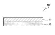
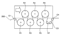
- FIG. 1 is a schematic cross-sectional view of a polarizing plate according to an embodiment of the present invention. It is a schematic diagram showing an example of dry shrinkage processing using a heating roll in a manufacturing method of a polarizing plate by one embodiment of the present invention.
- FIG. 1 is a schematic cross-sectional view of a polarizing plate according to one embodiment of the present invention.
- the illustrated polarizing plate 100 includes a polarizer 10 and a protective layer 20 disposed on one side of the polarizer 10.
- the thickness of the polarizer 10 is preferably 8 ⁇ m or less.
- another protective layer (not shown) may be provided on the side of the polarizer 10 opposite to the protective layer 20.
- the polarizing plate 100 may be arranged on the viewing side of the display cell or on the side opposite to the viewing side (back side).
- the protective layer 20 may be arranged on the display cell side or on the opposite side (outside) to the display cell.
- the polarizing plate 100 is arranged on the viewing side of the display cell (as a result, the image display device), and the protective layer 20 is arranged on the viewing side (the side opposite to the display cell).
- the polarizing plate may have a long shape or a sheet shape. When the polarizing plate has a long shape, it is preferably rolled into a polarizing roll.
- the polarizing plate has a pressure-sensitive adhesive layer as the outermost layer on one side (typically, the side opposite to the protective layer 20 of the polarizer 10), and can be attached to a display cell. ing. If necessary, a surface protective film and/or a carrier film may be detachably temporarily attached to the polarizing plate to reinforce and/or support the polarizing plate.
- a separator is detachably temporarily attached to the surface of the pressure-sensitive adhesive layer to protect the pressure-sensitive adhesive layer until actual use and to roll the polarizing plate.
- the protective layer 20 is composed of a solidified product of a coating film of an organic solvent solution of a thermoplastic acrylic resin.
- the protective layer can be made extremely thin (for example, 10 ⁇ m or less).
- the protective layer can be formed directly on the polarizer (that is, without interposing the adhesive layer or the pressure-sensitive adhesive layer).
- the polarizer and the protective layer are very thin as described above, and the adhesive layer or the pressure-sensitive adhesive layer can be omitted. Therefore, the total thickness of the polarizing plate can be made extremely thin. it can.
- the total thickness of the polarizing plate is, for example, 40 ⁇ m or less, preferably 30 ⁇ m or less, more preferably 20 ⁇ m or less, further preferably 10 ⁇ m or less, and particularly preferably 7 ⁇ m or less.
- the lower limit of the total thickness of the polarizing plate can be, for example, 4 ⁇ m.
- the glass transition temperature (Tg) of the protective layer 20 is 95° C. or higher, preferably 100° C. or higher, more preferably 105° C. or higher, further preferably 110° C. or higher. And particularly preferably 115° C. or higher.
- Tg of the protective layer is in such a range, it is very thin due to a synergistic effect with the effect of forming the protective layer from the solidified material of the coating film of the organic solvent solution of the thermoplastic acrylic resin.
- the Tg of the protective layer is preferably 300°C or lower, more preferably 250°C or lower, further preferably 200°C or lower, and particularly preferably 160°C or lower.
- the moldability can be excellent.
- the change amount ⁇ Ts of the single-piece transmittance Ts and the change amount ⁇ P of the polarization degree P after standing for 48 hours in an environment of 85° C. and 85% RH are very small.
- the simple substance transmittance Ts can be measured using, for example, an ultraviolet-visible spectrophotometer (manufactured by JASCO Corporation, product name “V7100”).
- the polarization degree P is calculated by the following formula from the simple substance transmittance (Ts), the parallel transmittance (Tp), and the orthogonal transmittance (Tc) measured using an ultraviolet-visible spectrophotometer.
- Polarization degree (P)(%) ⁇ (Tp-Tc)/(Tp+Tc) ⁇ 1/2 ⁇ 100
- Ts, Tp, and Tc are Y values measured by a 2 degree visual field (C light source) of JIS Z 8701 and subjected to luminosity correction.
- Ts and P are substantially characteristics of the polarizer.
- ⁇ Ts and ⁇ P are respectively calculated by the following equations.
- Ts 0 is the unit transmittance before standing (initial)
- Ts 48 is the unit transmittance after standing
- P 0 is the polarization degree before standing (initial)
- P 48 is the group after standing. It is the degree of polarization.
- ⁇ Ts is preferably 3.0% or less, more preferably 2.7% or less, and further preferably 2.4% or less.
- ⁇ P is preferably ⁇ 0.05% to 0%, more preferably ⁇ 0.03% to 0%, and further preferably ⁇ 0.01% to 0%.
- the polarizing plate of the present invention is extremely thin as described above, it can be suitably applied to a flexible image display device. More preferably, the image display device has a curved shape (substantially a curved display screen) and/or is bendable or bendable. Specific examples of the image display device include a liquid crystal display device and an electroluminescence (EL) display device (for example, an organic EL display device and an inorganic EL display device). Needless to say, the above description does not prevent the polarizing plate of the present invention from being applied to an ordinary image display device.
- EL electroluminescence
- Polarizer Any appropriate polarizer can be adopted as the polarizer.
- the polarizer can be typically manufactured by using a laminate of two or more layers. The method for producing the polarizer will be described later in the section D as a method for producing the polarizing plate.
- the thickness of the polarizer is preferably 1 ⁇ m to 8 ⁇ m, more preferably 1 ⁇ m to 7 ⁇ m, and further preferably 2 ⁇ m to 5 ⁇ m.
- the boric acid content of the polarizer is preferably 10% by weight or more, and more preferably 13% by weight to 25% by weight.
- the boric acid content can be calculated as the amount of boric acid contained in the polarizer per unit weight from the neutralization method using the following formula.
- the iodine content of the polarizer is preferably 2% by weight or more, more preferably 2% by weight to 10% by weight.
- the iodine content of the polarizer is in such a range, the curl at the time of laminating is favorably maintained due to the synergistic effect with the above boric acid content, and the curl at the time of heating is maintained. It is possible to improve the appearance durability at the time of heating while suppressing the above.
- the “iodine content” means the total amount of iodine contained in the polarizer (PVA-based resin film).
- iodine is present in the polarizer in the form of iodine ion (I ⁇ ), iodine molecule (I 2 ), polyiodine ion (I 3 ⁇ , I 5 ⁇ ), etc.
- the iodine content means the amount of iodine including all of these forms.
- the iodine content can be calculated, for example, by a calibration curve method of fluorescent X-ray analysis.
- the polyiodine ion is present in the polarizer in a state of forming a PVA-iodine complex. By forming such a complex, absorption dichroism can be exhibited in the wavelength range of visible light.
- the complex of PVA and triiodide ion (PVA ⁇ I 3 ⁇ ) has an absorption peak near 470 nm, and the complex of PVA and pentaiodide ion (PVA ⁇ I 5 ⁇ ) is around 600 nm. Has an absorption peak at.
- polyiodine ions can absorb light in a wide range of visible light, depending on their morphology.
- iodine ion (I ⁇ ) has an absorption peak around 230 nm and does not substantially participate in absorption of visible light. Therefore, the polyiodine ion existing in the form of a complex with PVA may be mainly involved in the absorption performance of the polarizer.
- the polarizer preferably exhibits absorption dichroism at any wavelength of 380 nm to 780 nm.
- the single transmittance Ts of the polarizer is preferably 40% to 48%, more preferably 41% to 46%.
- the polarization degree P of the polarizer is preferably 97.0% or more, more preferably 99.0% or more, and further preferably 99.9% or more.
- the protective layer is composed of a solidified product of a coating film of a solution of a thermoplastic acrylic resin (hereinafter simply referred to as an acrylic resin) in an organic solvent.
- an acrylic resin a thermoplastic acrylic resin
- the constituents of the protective layer will be specifically described below, and then the characteristics of the protective layer will be described.
- Acrylic resin The Tg of the acrylic resin (including a blend of two or more kinds of acrylic resins and a blend of the acrylic resin and another resin as described later) is as described in the section A regarding the protective layer. is there.
- the acrylic resin any appropriate acrylic resin can be adopted as long as it has the Tg as described above.
- the acrylic resin typically contains an alkyl (meth)acrylate as a main component as a monomer unit (repeating unit).
- (meth)acrylic means acrylic and/or methacrylic.
- alkyl (meth)acrylate constituting the main skeleton of the acrylic resin include linear or branched alkyl groups having 1 to 18 carbon atoms. These can be used alone or in combination.
- any appropriate copolymerization monomer may be introduced into the acrylic resin by copolymerization.
- the repeating unit derived from an alkyl (meth)acrylate is typically represented by the following general formula (1):
- R 4 represents a hydrogen atom or a methyl group
- R 5 represents a hydrogen atom or an optionally substituted aliphatic or alicyclic hydrocarbon group having 1 to 6 carbon atoms. Show.
- the substituent include halogen and hydroxyl group.
- Specific examples of the alkyl (meth)acrylate include methyl (meth)acrylate, ethyl (meth)acrylate, n-propyl (meth)acrylate, n-butyl (meth)acrylate, and t-(meth)acrylate.
- R 5 is preferably a hydrogen atom or a methyl group.
- the acrylic resin may include only a single alkyl (meth)acrylate unit, or may include a plurality of alkyl (meth)acrylate units having different R 4 and R 5 in the general formula (1). Good.
- the content ratio of the alkyl (meth)acrylate unit in the acrylic resin is preferably 50 mol% to 98 mol%, more preferably 55 mol% to 98 mol%, further preferably 60 mol% to 98 mol%, and particularly preferably It is 65 mol% to 98 mol%, most preferably 70 mol% to 97 mol%. If the content ratio is less than 50 mol %, the effects (for example, high heat resistance and high transparency) derived from the alkyl (meth)acrylate unit may not be sufficiently exhibited. When the content ratio is more than 98 mol%, the resin becomes brittle and easily cracked, high mechanical strength cannot be sufficiently exhibited, and productivity may be deteriorated.
- the acrylic resin preferably has a repeating unit containing a ring structure.
- the repeating unit containing a ring structure include a lactone ring unit, a glutaric anhydride unit, a glutarimide unit, a maleic anhydride unit, and a maleimide (N-substituted maleimide) unit.
- the repeating unit containing a ring structure only one kind may be contained in the repeating unit of the acrylic resin, or two or more kinds may be contained.
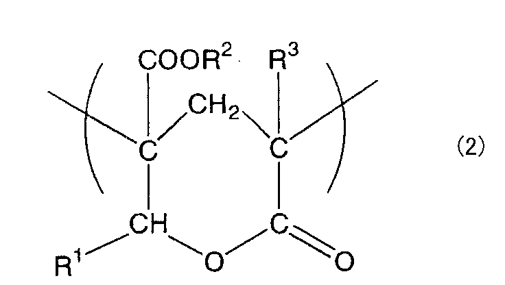
- the lactone ring unit is preferably represented by the following general formula (2):
- R 1 , R 2 and R 3 each independently represent a hydrogen atom or an organic residue having 1 to 20 carbon atoms.
- the organic residue may contain an oxygen atom.
- the acrylic resin may contain only a single lactone ring unit, or may contain a plurality of lactone ring units having different R 1 , R 2 and R 3 in the general formula (2). ..
- the acrylic resin having a lactone ring unit is described in, for example, JP-A-2008-181078, and the description in that publication is incorporated herein by reference.
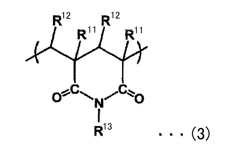
- the glutarimide unit is preferably represented by the following general formula (3):
- R 11 and R 12 each independently represent hydrogen or an alkyl group having 1 to 8 carbon atoms
- R 13 is an alkyl group having 1 to 18 carbon atoms or 3 to 12 carbon atoms. Is a cycloalkyl group or an aryl group having 6 to 10 carbon atoms.
- R 11 and R 12 are each independently hydrogen or a methyl group
- R 13 is hydrogen, a methyl group, a butyl group or a cyclohexyl group. More preferably, R 11 is a methyl group, R 12 is hydrogen and R 13 is a methyl group.
- the acrylic resin may contain only a single glutarimide unit, or may contain a plurality of glutarimide units having different R 11 , R 12 and R 13 in the general formula (3). ..
- the acrylic resin having a glutarimide unit is disclosed in, for example, JP-A-2006-309033, JP-A-2006-317560, JP-A-2006-328334, JP-A-2006-337491, and JP-A-2006-337492. It is described in Japanese Patent Laid-Open No. 2006-337493 and Japanese Patent Laid-Open No. 2006-337569, the description of which is incorporated herein by reference.
- the glutaric anhydride unit the above description regarding the glutarimide unit is applied, except that the nitrogen atom substituted with R 13 in the general formula (3) becomes an oxygen atom.
- maleic anhydride unit and the maleimide (N-substituted maleimide) unit are specified by their names, so a detailed description will be omitted.
- the content ratio of the repeating unit containing a ring structure in the acrylic resin is preferably 1 mol% to 50 mol%, more preferably 10 mol% to 40 mol%, and further preferably 20 mol% to 30 mol%. If the content ratio is too low, Tg may be less than 110° C., and the resulting protective layer may have insufficient heat resistance, solvent resistance, and surface hardness. If the content ratio is too large, moldability and transparency may be insufficient.
- the acrylic resin may contain a repeating unit other than the repeating unit containing an alkyl (meth)acrylate unit and a ring structure.
- a repeating unit include a repeating unit derived from a vinyl-based monomer copolymerizable with the monomer constituting the above unit (another vinyl-based monomer unit).
- other vinyl monomers include acrylic acid, methacrylic acid, crotonic acid, 2-(hydroxymethyl)acrylic acid, 2-(hydroxyethyl)acrylic acid, acrylonitrile, methacrylonitrile, ethacrylonitrile and allyl.
- Glycidyl ether maleic anhydride, itaconic anhydride, N-methylmaleimide, N-ethylmaleimide, N-cyclohexylmaleimide, aminoethyl acrylate, propylaminoethyl acrylate, dimethylaminoethyl methacrylate, ethylaminopropyl methacrylate, methacryl Acid cyclohexylaminoethyl, N-vinyldiethylamine, N-acetylvinylamine, allylamine, methallylamine, N-methylallylamine, 2-isopropenyl-oxazoline, 2-vinyl-oxazoline, 2-acroyl-oxazoline, N-phenylmaleimide, Examples thereof include phenylaminoethyl methacrylate, styrene, ⁇ -methylstyrene, p-glycidylstyrene, p-
- the weight average molecular weight of the acrylic resin is preferably 1,000 to 2,000,000, more preferably 5,000 to 1,000,000, further preferably 10,000 to 500,000, particularly preferably 50,000 to 500,000, and most preferably 60,000 to 150,000.
- the weight average molecular weight can be determined by polystyrene conversion using, for example, a gel permeation chromatograph (GPC system, manufactured by Tosoh Corporation). Tetrahydrofuran may be used as the solvent.
- the acrylic resin can be polymerized by any suitable polymerization method using the above monomer units in an appropriate combination. Two or more types of acrylic resins having different monomer units may be blended.
- an acrylic resin and another resin may be used together. That is, you may copolymerize the monomer component which comprises an acrylic resin, and the monomer component which comprises another resin, and you may use this copolymer for shaping
- the blend may be used for forming the protective layer.
- the other resin include thermoplastic resins such as styrene resins, polyethylene, polypropylene, polyamide, polyphenylene sulfide, polyether ether ketone, polyester, polysulfone, polyphenylene oxide, polyacetal, polyimide, and polyetherimide.
- the kind and blending amount of the resin used in combination can be appropriately set depending on the purpose and desired properties of the obtained film.
- a styrene resin preferably an acrylonitrile-styrene copolymer
- a retardation control agent preferably an acrylonitrile-styrene copolymer
- the content of the acrylic resin in the blend of the acrylic resin and the other resin is preferably 50% by weight to 100% by weight, more preferably 60% by weight to 100% by weight. %, more preferably 70 to 100% by weight, particularly preferably 80 to 100% by weight. If the content is less than 50% by weight, the high heat resistance and high transparency inherent in the acrylic resin may not be sufficiently reflected.
- the protective layer is composed of a solidified product of a coating film of an organic solvent solution of an acrylic resin. With such a solidified product of the coating film, the thickness can be remarkably reduced as compared with the extruded film.
- the thickness of the protective layer is 10 ⁇ m or less, preferably 7 ⁇ m or less, more preferably 5 ⁇ m or less, and further preferably 3 ⁇ m or less.
- the lower limit of the thickness of the protective layer may be, for example, 1 ⁇ m.
- such a solidified product of the coating film is more difficult to form during film formation than a cured product of a thermosetting resin or an active energy ray curable resin (for example, an ultraviolet curable resin). Since the shrinkage is small and the residual monomer and the like are not included, the deterioration of the film itself is suppressed, and an adverse effect on the polarizing plate (polarizer) due to the residual monomer and the like can be suppressed. Furthermore, since it has lower hygroscopicity and moisture permeability than a solidified product of an aqueous coating film such as an aqueous solution or an aqueous dispersion, it has an advantage that it is excellent in humidification durability. As a result, it is possible to realize a polarizing plate having excellent durability that can maintain the optical characteristics even under a heating and humidifying environment.
- a thermosetting resin or an active energy ray curable resin for example, an ultraviolet curable resin.
- the Tg of the protective layer is as described in Section A above.
- the iodine adsorption amount of the protective layer is preferably 4.0% by weight or less, more preferably 3.0% by weight or less, further preferably 2.0% by weight or less, and particularly preferably 1.0% by weight. % Or less, particularly preferably 0.5% by weight or less.
- a polarizing plate having further excellent durability can be obtained.
- the iodine adsorption amount can be measured by the method described in Examples below.
- the protective layer preferably has substantially optical isotropy.
- “having substantially optical isotropy” means that the in-plane retardation Re(550) is 0 nm to 10 nm and the thickness direction retardation Rth(550) is ⁇ 20 nm to +10 nm. There is something.
- the in-plane retardation Re(550) is more preferably 0 nm to 5 nm, further preferably 0 nm to 3 nm, and particularly preferably 0 nm to 2 nm.
- the retardation Rth(550) in the thickness direction is more preferably ⁇ 5 nm to +5 nm, further preferably ⁇ 3 nm to +3 nm, and particularly preferably ⁇ 2 nm to +2 nm.
- Re(550) and Rth(550) of the protective layer are in such ranges, it is possible to prevent adverse effects on display characteristics when a polarizing plate including the protective layer is applied to an image display device.
- Rth(550) is the retardation in the thickness direction of the film measured with light having a wavelength of 550 nm at 23°C.
- nx is the refractive index in the direction in which the in-plane refractive index is maximum (that is, the slow axis direction)
- ny is the direction in the plane that is orthogonal to the slow axis (that is, the fast axis direction).
- the refractive index, nz is the refractive index in the thickness direction
- d is the film thickness (nm).
- the light transmittance is preferably 85% or more, more preferably 88% or more, and further preferably 90% or more. When the light transmittance is in such a range, desired transparency can be secured.
- the light transmittance can be measured, for example, by a method according to ASTM-D-1003.
- the haze is preferably 5% or less, more preferably 3% or less, further preferably 1.5% or less, particularly preferably 1% or less.
- the haze is 5% or less, a good clear feeling can be given to the film. Further, even when it is used for the viewing side polarizing plate of the image display device, the displayed contents can be viewed well.
- the YI in the protective layer having a thickness of 3 ⁇ m is preferably 1.27 or less, more preferably 1.25 or less, further preferably 1.23 or less, and particularly preferably 1.20 or less.
- YI is, for example, from tristimulus values (X, Y, Z) of color obtained by measurement using a high-speed integrating sphere type spectral transmittance measuring device (trade name DOT-3C: manufactured by Murakami Color Research Laboratory). , Can be obtained by the following formula.
- YI [(1.28X-1.06Z)/Y] ⁇ 100
- the b value (scale of hue according to Hunter's color system) when the thickness of the protective layer is 3 ⁇ m is preferably less than 1.5, and more preferably 1.0 or less. When the b value is 1.5 or more, an undesired tint may appear.
- the b value is obtained by, for example, cutting a sample of the film forming the protective layer into 3 cm squares, and using a high-speed integrating sphere type spectral transmittance measuring instrument (trade name DOT-3C: manufactured by Murakami Color Research Laboratory). Is measured and the hue is evaluated according to Hunter's color system.
- the protective layer may contain any appropriate additive depending on the purpose.
- the additives include ultraviolet absorbers, leveling agents, hindered phenol-based, phosphorus-based, sulfur-based, and other antioxidants; light stabilizers, weather stabilizers, heat stabilizers, and other stabilizers; glass fibers; Reinforcing materials such as carbon fibers; near infrared absorbers; flame retardants such as tris(dibromopropyl)phosphate, triallyl phosphate, antimony oxide; antistatic agents such as anionic, cationic and nonionic surfactants; inorganic pigments Colorants such as organic pigments and dyes, organic fillers or inorganic fillers, resin modifiers, organic fillers and inorganic fillers, plasticizers, lubricants, antistatic agents, flame retardants, and the like.
- the additive may be added during the polymerization of the acrylic resin or may be added to the solution during the film formation. The kind, number, combination, addition amount and the like of the additive
- An easy-adhesion layer may be formed on the polarizer side of the protective layer.
- the easy-adhesion layer contains, for example, a water-based polyurethane and an oxazoline-based crosslinking agent. By forming such an easy-adhesion layer, the adhesion between the protective layer and the polarizer can be enhanced.
- a hard coat layer may be formed on the protective layer. The hard coat layer can be formed when the protective layer is used as a protective layer on the viewing side of the viewing side polarizing plate. When both the easy adhesion layer and the hard coat layer are formed, typically, they can be formed on different sides of the protective layer, respectively.
- the method for producing the polarizer according to the above item B is a polyvinyl alcohol-based resin containing a halide and a polyvinyl alcohol-based resin (PVA-based resin) on one side of a long thermoplastic resin substrate.
- a layer (PVA-based resin layer) is formed into a laminated body, and the laminated body is subjected to an in-air auxiliary stretching treatment, a dyeing treatment, an underwater stretching treatment, and heating while being conveyed in the longitudinal direction. And a drying shrinkage treatment for shrinking by 2% or more in this order.
- the content of the halide in the PVA-based resin layer is preferably 5 to 20 parts by weight with respect to 100 parts by weight of the PVA-based resin.
- the drying shrinkage treatment is preferably performed using a heating roll, and the temperature of the heating roll is preferably 60° C. to 120° C. According to such a manufacturing method, the above polarizer can be obtained.
- a polarizer having excellent optical characteristics (typically, single transmittance and degree of polarization) and suppressing variations in optical characteristics.
- the drying shrinkage treatment step by using a heating roll in the drying shrinkage treatment step, it is possible to uniformly shrink the entire laminate while transporting the laminate. As a result, not only can the optical characteristics of the obtained polarizer be enhanced, but also polarizers with excellent optical characteristics can be stably produced, and variations in optical characteristics of the polarizer (particularly, single transmittance) can be suppressed. can do.
- the halide and the drying shrinkage treatment will be described below. Details of manufacturing methods other than these are described in, for example, Japanese Patent Application Laid-Open No. 2012-73580. The entire disclosure of this publication is incorporated herein by reference.
- a PVA-based resin layer containing a halide and a PVA-based resin can be formed by applying a coating liquid containing a halide and a PVA-based resin on a thermoplastic resin substrate and drying the coating film.
- the coating liquid is typically a solution prepared by dissolving the halide and the PVA resin in a solvent.
- the solvent include water, dimethyl sulfoxide, dimethylformamide, dimethylacetamide, N-methylpyrrolidone, various glycols, polyhydric alcohols such as trimethylolpropane, and amines such as ethylenediamine and diethylenetriamine. These may be used alone or in combination of two or more. Of these, water is preferable.
- the concentration of the PVA resin in the solution is preferably 3 to 20 parts by weight with respect to 100 parts by weight of the solvent. With such a resin concentration, it is possible to form a uniform coating film in close contact with the thermoplastic resin substrate.
- any suitable halide may be adopted as the halide.
- examples include iodide and sodium chloride.
- examples of iodides include potassium iodide, sodium iodide, and lithium iodide. Among these, potassium iodide is preferable.
- the amount of the halide in the coating liquid is preferably 5 to 20 parts by weight, more preferably 10 to 15 parts by weight, based on 100 parts by weight of the PVA-based resin. If the amount of the halide is too large, the halide may bleed out and the resulting polarizer may become cloudy.
- the orientation of the polyvinyl alcohol molecules in the PVA-based resin is increased.
- the stretched PVA-based resin layer is immersed in a liquid containing water, the polyvinyl alcohol molecules The orientation may be disturbed and the orientation may be deteriorated.
- the laminate can be stretched in boric acid water at a relatively high temperature to stabilize the stretching of the thermoplastic resin base material. In the case of stretching, the above-mentioned tendency of decreasing the degree of orientation is remarkable.
- stretching of a PVA film alone in boric acid water is generally performed at 60° C.
- stretching of a laminate of A-PET (thermoplastic resin substrate) and PVA-based resin layer is performed. It is carried out at a high temperature of around 70° C.
- the orientation of PVA in the initial stage of stretching may be lowered in a stage before being raised by underwater stretching.
- by producing a laminate of a PVA-based resin layer containing a halide and a thermoplastic resin substrate and stretching the laminate at high temperature in air (auxiliary stretching) before stretching in boric acid water.
- the crystallization of the PVA-based resin in the PVA-based resin layer of the laminate after the auxiliary stretching can be promoted.
- the PVA-based resin layer is immersed in a liquid, the disorder of the alignment of the polyvinyl alcohol molecules and the deterioration of the orientation can be suppressed as compared with the case where the PVA-based resin layer does not contain a halide.
- the optical characteristics of the polarizer obtained through a treatment step of immersing the laminate in a liquid such as a dyeing treatment and an underwater stretching treatment, can be improved.
- the drying shrinkage treatment may be performed by zone heating performed by heating the entire zone, or may be performed by heating the transport roll (using a so-called heating roll) (heating roll drying method). Both are preferably used.
- a heating roll By drying using a heating roll, it is possible to efficiently suppress the curling of the laminate by heating and to manufacture a polarizer having an excellent appearance.
- the crystallization of the thermoplastic resin substrate can be efficiently promoted to increase the crystallinity, which is relatively low. Even at the drying temperature, the crystallinity of the thermoplastic resin substrate can be satisfactorily increased.
- the rigidity of the thermoplastic resin base material increases, and the thermoplastic resin base material can withstand the shrinkage of the PVA-based resin layer due to drying, and curling is suppressed.
- the laminated body can be improved in optical characteristics by shrinking in the width direction by a drying shrinkage treatment. This is because the orientation of PVA and the PVA/iodine complex can be effectively enhanced.
- the shrinkage ratio in the width direction of the laminate by the dry shrinkage treatment is preferably 2% to 10%, more preferably 2% to 8%, and particularly preferably 4% to 6%.
- FIG. 2 is a schematic diagram showing an example of the drying shrinkage treatment.
- the laminate 200 is dried while being transported by the transport rolls R1 to R6 heated to a predetermined temperature and the guide rolls G1 to G4.
- the transport rolls R1 to R6 are arranged so as to alternately and continuously heat the surface of the PVA resin layer and the surface of the thermoplastic resin substrate.
- one surface of the laminate 200 for example, thermoplastic resin
- the transport rolls R1 to R6 may be arranged so that only the resin substrate surface) is continuously heated.
- the drying conditions can be controlled by adjusting the heating temperature of the transfer rolls (temperature of the heating rolls), the number of heating rolls, the contact time with the heating rolls, and the like.
- the temperature of the heating roll is preferably 60°C to 120°C, more preferably 65°C to 100°C, and particularly preferably 70°C to 80°C. It is possible to satisfactorily increase the crystallinity of the thermoplastic resin, satisfactorily suppress curling, and manufacture an optical laminate having extremely excellent durability.
- the temperature of the heating roll can be measured with a contact thermometer. In the illustrated example, six transport rolls are provided, but there is no particular limitation as long as there are multiple transport rolls. The number of transport rolls is usually 2 to 40, preferably 4 to 30.
- the contact time (total contact time) between the laminate and the heating roll is preferably 1 second to 300 seconds, more preferably 1 to 20 seconds, and further preferably 1 to 10 seconds.
- the heating roll may be provided in a heating furnace (for example, an oven) or may be provided in a normal production line (under room temperature environment). Preferably, it is provided in a heating furnace provided with a blowing means.
- a heating furnace provided with a blowing means.
- the temperature of hot air drying is preferably 30°C to 100°C.
- the hot air drying time is preferably 1 second to 300 seconds.
- the wind speed of the hot air is preferably about 10 m/s to 30 m/s.
- the wind velocity is the wind velocity in the heating furnace, and can be measured by a mini vane type digital anemometer.
- a washing treatment is performed after the underwater stretching treatment and before the drying shrinkage treatment.
- the cleaning treatment is typically performed by immersing the PVA-based resin layer in an aqueous potassium iodide solution.
- thermoplastic resin substrate/polarizer a laminate of the thermoplastic resin substrate/polarizer.
- a protective film is formed by applying a solution of an acrylic resin in an organic solvent to form a coating film on the surface of the laminate obtained in the above section D-1 and solidifying the coating film. ..
- any suitable organic solvent that can dissolve or uniformly disperse the acrylic resin can be used.
- the organic solvent include ethyl acetate, toluene, methyl ethyl ketone (MEK), methyl isobutyl ketone (MIBK), cyclopentanone, and cyclohexanone.
- the concentration of the acrylic resin in the solution is preferably 3 to 20 parts by weight with respect to 100 parts by weight of the solvent. With such a resin concentration, it is possible to form a uniform coating film in close contact with the polarizer.
- the solution may be applied to any appropriate base material or may be applied to the polarizer.
- the solidified product of the coating film formed on the base material is transferred to the polarizer.
- the protective layer is directly formed on the polarizer by drying (solidifying) the coating film.
- the solution is applied to the polarizer and the protective layer is directly formed on the polarizer.
- the adhesive layer or the pressure-sensitive adhesive layer required for transfer can be omitted, so that the polarizing plate can be made thinner.
- Any appropriate method can be adopted as a method for applying the solution. Specific examples thereof include roll coating, spin coating, wire bar coating, dip coating, die coating, curtain coating, spray coating, knife coating (comma coating, etc.).
- a protective layer can be formed by drying (solidifying) the coating film of the solution.
- the drying temperature is preferably 100°C or lower, more preferably 50°C to 70°C. When the drying temperature is in such a range, it is possible to prevent the polarizer from being adversely affected.
- the drying time can vary depending on the drying temperature. The drying time can be, for example, 1 minute to 10 minutes.
- a protective layer is formed as described above, and as a result, a laminate of a thermoplastic resin substrate/polarizer/protective layer can be obtained.
- a polarizing plate having the polarizer 10 and the protective layer 20 as shown in FIG. 1 can be obtained.
- a resin film forming another protective layer is attached to the polarizer surface of the thermoplastic resin substrate/polarizer laminate, and then the thermoplastic resin substrate is peeled off to form a protective layer on the peeled surface. May be. In this case, a polarizing plate further having another protective layer can be obtained.
- the obtained coating film was peeled from the substrate and cut into 1 cm ⁇ 1 cm (1 cm 2 ) to obtain a measurement sample.
- the measurement sample was subjected to the combustion IC method, and the amount of iodine in the sample was quantitatively analyzed. Specifically, it is as follows.
- the measurement sample was collected and weighed in a headspace vial (20 mL capacity).
- a vial (2 mL capacity) containing 1 mL of an iodine solution iodine concentration 1% by weight, potassium iodide concentration 7% by weight
- this headspace vial is heated in a dryer at 65°C for 6 hours, and a sample after heating is collected in a ceramic port and burned using an automatic combustion device, and the generated gas is collected in an absorption liquid and then quantified. Analysis was performed to determine the weight percent of adsorbed iodine.
- the equipment used was as follows. ⁇ Automatic sample combustor: "AQF-2100H” manufactured by Mitsubishi Chemical Analytical Co., Ltd.
- IC anion: "ICS-3000" manufactured by Thermo Fisher Scientific (3) Color Loss From the polarizing plates obtained in Examples and Comparative Examples, a test piece (50 mm ⁇ 50 mm) having two sides facing each other in the direction orthogonal to the absorption axis direction of the polarizer and the absorption axis direction was cut out. .. The test piece is attached to a non-alkali glass plate with an adhesive so that the protective layer is on the outside to give a test sample, and the test sample is left to stand in an oven at 85° C. and 85% RH for 48 hours to be heated and humidified.
- a test piece is attached to an alkali-free glass plate with an adhesive so that the protective layer is on the outside to form a test sample, and an ultraviolet-visible spectrophotometer (manufactured by JASCO Corporation, product name "V7100") is used for the test sample. Then, the simple substance transmittance (Ts), the parallel transmittance (Tp), and the orthogonal transmittance (Tc) were measured, and the polarization degree (P) was calculated by the following equation. At this time, the measurement light was made incident from the protective layer side.
- Polarization degree (P)(%) ⁇ (Tp-Tc)/(Tp+Tc) ⁇ 1/2 ⁇ 100
- Ts, Tp, and Tc are Y values measured by a 2 degree visual field (C light source) of JIS Z 8701 and subjected to luminosity correction. Further, Ts and P are substantially characteristics of the polarizer.
- the polarizing plate was left to stand in an oven at 85° C. and 85% RH for 48 hours to be heated and humidified (heating test). From the single transmittance Ts 0 before the heating test and the single transmittance Ts 48 after the heating test, The single-unit transmittance change amount ⁇ Ts was calculated using the following formula.
- ⁇ Ts (%) Ts 48 ⁇ Ts 0
- the polarization degree change amount ⁇ P was determined from the polarization degree P 0 before the heating test and the polarization degree P 48 after the heating test using the following formula.
- ⁇ P(%) P 48 ⁇ P 0
- the heating test was conducted by preparing a test sample in the same manner as in the case of color loss.
- Example 1> Production of Laminate of Polarizer/Resin Base Material Amorphous isophthalic copolymerized polyethylene terephthalate film (thickness: 100 ⁇ m) having a long shape, a water absorption rate of 0.75% and a Tg of about 75° C. as a resin base material. Was used. Corona treatment was applied to one side of the resin substrate.
- Polyvinyl alcohol (polymerization degree: 4200, saponification degree: 99.2 mol%) and acetoacetyl-modified PVA (manufactured by Nippon Synthetic Chemical Industry Co., Ltd., trade name "Gosephimmer Z410" in a ratio of 9:1 100 weight of PVA-based resin
- 13 parts by weight of potassium iodide was added to prepare a PVA aqueous solution (coating solution).
- the PVA aqueous solution was applied to the corona-treated surface of the resin substrate and dried at 60° C. to form a PVA-based resin layer having a thickness of 13 ⁇ m, and a laminate was prepared.
- the obtained laminate was uniaxially stretched 2.4 times in the longitudinal direction (longitudinal direction) between rolls having different peripheral speeds in an oven at 130° C. (in-air auxiliary stretching treatment).
- the laminate was immersed in an insolubilizing bath (a boric acid aqueous solution obtained by mixing 4 parts by weight of boric acid with 100 parts by weight of water) having a liquid temperature of 40° C. for 30 seconds (insolubilization treatment).
- a dyeing bath having a liquid temperature of 30° C. an iodine aqueous solution obtained by mixing iodine and potassium iodide in a weight ratio of 1:7 with respect to 100 parts by weight of water
- a cycloolefin film (ZT-12, thickness 23 ⁇ m, manufactured by Nippon Zeon Co., Ltd.) as a film constituting another protective layer was placed via an ultraviolet curable adhesive. Pasted together. Specifically, the curable adhesive was applied so that the total thickness was 1.0 ⁇ m, and the curable adhesive was attached using a roll machine. Then, UV rays were irradiated from the film side to cure the adhesive. Then, the resin substrate was peeled off to obtain a polarizing plate having another protective layer (ZT-12)/polarizer configuration.
- an acrylic resin (30 mol% of lactone ring unit), which is polymethylmethacrylate having a lactone ring unit, was dissolved in 80 parts of methyl ethyl ketone to obtain an acrylic resin solution (20%).
- This acrylic resin solution is applied to the surface of the polarizer of the polarizing plate obtained above using a wire bar, the coating film is dried at 60° C. for 5 minutes, and the protective layer is formed as a solidified product of the coating film. Formed.
- the protective layer had a thickness of 3 ⁇ m, a Tg of 119° C., and an iodine adsorption amount of 0.25% by weight.
- a polarizing plate having a structure of protective layer (solidified product of coating film)/polarizer/another protective layer (ZT-12) was obtained.
- the obtained polarizing plate was subjected to the above evaluations (3) and (4). Furthermore, the presence or absence of shrinkage after forming the protective layer was visually observed. The results are shown in Table 1.
- Example 2 Same as Example 1 except that an acrylic resin (maleic anhydride unit: 7 mol %), which is a polymethylmethacrylate having a maleic anhydride unit, is used in place of the acrylic resin, which is a polymethylmethacrylate having a lactone ring unit.
- the protective layer had a thickness of 3 ⁇ m and a Tg of 115° C.
- a polarizing plate was produced in the same manner as in Example 1 except that this protective layer was used. The obtained polarizing plate was subjected to the same evaluations as in Example 1. The results are shown in Table 1.
- Example 3 Example 1 except that 100% polymethylmethacrylate acrylic resin (Kusumoto Kasei Co., product name "B-728") was used instead of polymethylmethacrylate acrylic resin having lactone ring unit.
- a protective layer was formed in the same manner.
- the protective layer had a thickness of 3 ⁇ m, a Tg of 116° C., and an iodine adsorption amount of 0.34% by weight.
- a polarizing plate was produced in the same manner as in Example 1 except that this protective layer was used. The obtained polarizing plate was subjected to the same evaluations as in Example 1. The results are shown in Table 1.
- Example 4 Same as Example 1 except that an acrylic resin that is a polymethylmethacrylate having a glutarimide ring unit (4 mol% of a glutarimide ring unit) is used instead of an acrylic resin that is a polymethylmethacrylate having a lactone ring unit.
- an acrylic resin that is a polymethylmethacrylate having a glutarimide ring unit (4 mol% of a glutarimide ring unit) is used instead of an acrylic resin that is a polymethylmethacrylate having a lactone ring unit.
- the thickness of the protective layer was 3 ⁇ m
- the Tg was 103° C.
- the iodine adsorption amount was 2.3% by weight.
- a polarizing plate was produced in the same manner as in Example 1 except that this protective layer was used.
- the obtained polarizing plate was subjected to the same evaluations as in Example 1. The results are shown in Table 1.
- Example 5 A protective layer was formed in the same manner as in Example 1 except that an acrylic resin (lactone ring unit: 20 mol%), which was a different polymethylmethacrylate having a lactone ring unit, was used.
- the protective layer had a thickness of 3 ⁇ m, a Tg of 104° C., and an iodine adsorption amount of 2.8% by weight.
- a polarizing plate was produced in the same manner as in Example 1 except that this protective layer was used. The obtained polarizing plate was subjected to the same evaluations as in Example 1. The results are shown in Table 1.
- Example 6> In the same manner as in Example 1 except that an acrylic resin which is a copolymer of methyl methacrylate/butyl methacrylate (molar ratio 80/20) was used in place of the acrylic resin which was polymethylmethacrylate having a lactone ring unit. A protective layer was formed. The thickness of the protective layer was 3 ⁇ m, Tg was 95° C., and the iodine adsorption amount was 3.8% by weight. A polarizing plate was produced in the same manner as in Example 1 except that this protective layer was used. The obtained polarizing plate was subjected to the same evaluations as in Example 1. The results are shown in Table 1.
- a protective layer (cured product) was prepared in the same manner as in Example 1 except that an ultraviolet curable acrylic resin (manufactured by Kyoeisha Chemical Co., Ltd., product name “Light acrylate HPP-A”, hydroxypivalate neopentyl glycol acrylic acid adduct) was used. ) was formed. Specifically, a composition containing 97% by weight of the acrylic resin and 3% by weight of a photopolymerization initiator (Irgacure 907, manufactured by BASF) is coated on a polarizer, and a high pressure mercury lamp is used in a nitrogen atmosphere.
- an ultraviolet curable acrylic resin manufactured by Kyoeisha Chemical Co., Ltd., product name “Light acrylate HPP-A”, hydroxypivalate neopentyl glycol acrylic acid adduct
- a photopolymerization initiator Irgacure 907, manufactured by BASF
- the protective layer had a thickness of 3 ⁇ m, a Tg of 83° C., and an iodine adsorption amount of 6.6% by weight.
- a polarizing plate was produced in the same manner as in Example 1 except that this protective layer was used. The obtained polarizing plate was subjected to the same evaluations as in Example 1. The results are shown in Table 1.
- a protective layer (cured product) was formed in the same manner as in Example 1 except that an ultraviolet curable epoxy resin (manufactured by Daicel, product name “Ceroxide 2021P”) was used. Specifically, a composition containing 95% by weight of the epoxy resin and 5% by weight of a photopolymerization initiator (CPI-100P, manufactured by San-Apro Co., Ltd.) is applied onto a polarizer, and a high pressure mercury lamp is applied in an air atmosphere. It was irradiated with ultraviolet rays at an integrated light amount of 500 mJ/cm 2 to form a cured layer (protective layer).
- CPI-100P photopolymerization initiator
- the protective layer had a thickness of 3 ⁇ m, a Tg of 95° C., and an iodine adsorption amount of 9% by weight.
- a polarizing plate was produced in the same manner as in Example 1 except that this protective layer was used. The obtained polarizing plate was subjected to the same evaluations as in Example 1. The results are shown in Table 1.
- a protective layer (solidified product of the coating film) was formed in the same manner as in Example 1 except that an aqueous polyester resin (manufactured by Nippon Synthetic Chemical Industry Co., Ltd., product name "Polyester WR905") was used.
- the thickness of the protective layer was 3 ⁇ m, and the iodine adsorption amount was 12% by weight.
- a polarizing plate was produced in the same manner as in Example 1 except that this protective layer was used. When the obtained polarizing plate was evaluated for color loss, it was found to be defective (“total loss”). Therefore, the single-element transmittance and the degree of polarization were not evaluated. The results are shown in Table 1.
- a protective layer (solidified product of the coating film) was formed in the same manner as in Example 1 except that an aqueous polyurethane resin (manufactured by Dai-ichi Kogyo Seiyaku Co., Ltd., product name "Superflex SF210") was used.
- the thickness of the protective layer was 3 ⁇ m
- the Tg was 107° C.
- the iodine adsorption amount was 19% by weight.
- a polarizing plate was produced in the same manner as in Example 1 except that this protective layer was used. When the obtained polarizing plate was evaluated for color loss, it was found to be defective (“total loss”). Therefore, the single-element transmittance and the degree of polarization were not evaluated. The results are shown in Table 1.
- Example 8 A protective layer (solidified product of the coating film) was formed in the same manner as in Example 1 except that an aqueous polyurethane resin (manufactured by Unitika Ltd., product name “Arrow Base SE1200”) was used. The thickness of the protective layer was 3 ⁇ m, and the iodine adsorption amount was 15% by weight.
- a polarizing plate was produced in the same manner as in Example 1 except that this protective layer was used. When the obtained polarizing plate was evaluated for color loss, it was found to be defective (“total loss”). Therefore, the single-element transmittance and the degree of polarization were not evaluated. The results are shown in Table 1.
- the polarizing plates of the examples of the present invention are extremely thin, but are suppressed in deterioration of optical properties even under a heating and humidifying environment, have excellent durability, and have a protective layer. It is a polarizing plate that can withstand practical use without shrinkage after formation.
- the polarizing plate of the present invention is suitable for use in an image display device.
- the image display device include portable devices such as personal digital assistants (PDAs), smartphones, mobile phones, watches, digital cameras, and portable game consoles; office automation devices such as personal computer monitors, notebook computers, and copy machines; video cameras, televisions. , Household electric appliances such as microwave ovens; back monitors, car navigation system monitors, car audio and other in-vehicle equipment; digital signage, commercial store information monitors and other display equipment; surveillance monitors and other security equipment; nursing care Nursing care/medical devices such as medical monitors and medical monitors.
- PDAs personal digital assistants
- office automation devices such as personal computer monitors, notebook computers, and copy machines
- video cameras televisions.
- Household electric appliances such as microwave ovens
- digital signage commercial store information monitors and other display equipment
- surveillance monitors and other security equipment surveillance monitors and other security equipment
Landscapes
- Physics & Mathematics (AREA)
- Chemical & Material Sciences (AREA)
- Optics & Photonics (AREA)
- General Physics & Mathematics (AREA)
- Nonlinear Science (AREA)
- Organic Chemistry (AREA)
- Engineering & Computer Science (AREA)
- Life Sciences & Earth Sciences (AREA)
- Materials Engineering (AREA)
- Wood Science & Technology (AREA)
- Crystallography & Structural Chemistry (AREA)
- Mathematical Physics (AREA)
- Health & Medical Sciences (AREA)
- Chemical Kinetics & Catalysis (AREA)
- Medicinal Chemistry (AREA)
- Polymers & Plastics (AREA)
- Polarising Elements (AREA)
- Liquid Crystal (AREA)
Abstract
Description
1つの実施形態においては、上記保護層の厚みは10μm以下である。
1つの実施形態においては、上記保護層のヨウ素吸着量は4.0重量%以下である。
1つの実施形態においては、上記熱可塑性アクリル系樹脂は、ラクトン環単位、無水グルタル酸単位、グルタルイミド単位、無水マレイン酸単位およびマレイミド単位からなる群から選択される少なくとも1つを有する。
1つの実施形態においては、上記保護層の面内位相差Re(550)は0nm~10nmであり、厚み方向の位相差Rth(550)が-20nm~+10nmである。
1つの実施形態においては、上記偏光板は、総厚みが10μm以下である。
1つの実施形態においては、上記偏光板は、画像表示装置の視認側に配置され、かつ、上記保護層は視認側に配置される。
本発明の別の局面によれば、偏光板ロールが提供される。この偏光板ロールは、上記の偏光板がロール状に巻回されてなる。
図1は、本発明の1つの実施形態による偏光板の概略断面図である。図示例の偏光板100は、偏光子10と、偏光子10の一方の側に配置された保護層20と、を有する。偏光子10の厚みは、好ましくは8μm以下である。必要に応じて、偏光子10の保護層20と反対側に別の保護層(図示せず)が設けられてもよい。偏光板100は、画像表示装置に適用される場合、表示セルの視認側に配置されてもよく、視認側と反対側(背面側)に配置されてもよい。いずれの場合も、保護層20は表示セル側に配置されてもよく、表示セルと反対側(外側)に配置されてもよい。1つの実施形態においては、偏光板100は、表示セル(結果として、画像表示装置)の視認側に配置され、かつ、保護層20は視認側(表示セルと反対側)に配置される。偏光板は、長尺状であってもよいし、枚葉状であってもよい。偏光板が長尺状である場合、好ましくは、ロール状に巻回されて偏光板ロールとされる。
偏光度(P)(%)={(Tp-Tc)/(Tp+Tc)}1/2×100
なお、上記Ts、TpおよびTcは、JIS Z 8701の2度視野(C光源)により測定し、視感度補正を行ったY値である。また、TsおよびPは、実質的には偏光子の特性である。ΔTsおよびΔPは、それぞれ下記式により求められる。
ΔTs(%)=Ts48-Ts0
ΔP(%)=P48-P0
ここで、Ts0は放置前(初期)の単体透過率であり、Ts48は放置後の単体透過率であり、P0は放置前(初期)の偏光度であり、P48は放置後の偏光度である。ΔTsは、好ましくは3.0%以下であり、より好ましくは2.7%以下であり、さらに好ましくは2.4%以下である。ΔPは、好ましくは-0.05%~0%であり、より好ましくは-0.03%~0%であり、さらに好ましくは-0.01%~0%である。
偏光子としては、任意の適切な偏光子が採用され得る。偏光子は、代表的には、二層以上の積層体を用いて作製され得る。偏光子の製造方法については、偏光板の製造方法としてD項で後述する。

保護層は、上記のとおり、熱可塑性アクリル系樹脂(以下、単にアクリル系樹脂と称する)の有機溶媒溶液の塗布膜の固化物で構成されている。以下、保護層の構成成分について具体的に説明し、次いで、保護層の特性を説明する。
アクリル系樹脂(後述のように、2種以上のアクリル系樹脂のブレンドおよびアクリル系樹脂と他の樹脂とのブレンドを含む)のTgは、保護層に関して上記A項で説明したとおりである。

保護層は、上記のとおり、アクリル系樹脂の有機溶媒溶液の塗布膜の固化物で構成されている。このような塗布膜の固化物であれば、押出成形フィルムに比べて厚みを格段に薄くすることができる。保護層の厚みは、上記のとおり10μm以下であり、好ましくは7μm以下であり、より好ましくは5μm以下であり、さらに好ましくは3μm以下である。保護層の厚みの下限は、例えば1μmであり得る。また、理論的には明らかではないが、このような塗布膜の固化物は、熱硬化性樹脂または活性エネルギー線硬化性樹脂(例えば、紫外線硬化性樹脂)の硬化物に比べてフィルム成形時の収縮が小さい、および、残存モノマー等が含まれないのでフィルム自体の劣化が抑制され、かつ、残存モノマー等に起因する偏光板(偏光子)に対する悪影響を抑制することができるという利点を有する。さらに、水溶液または水分散体のような水系の塗布膜の固化物に比べて吸湿性および透湿性が小さいので加湿耐久性に優れるという利点を有する。その結果、加熱加湿環境下においても光学特性を維持し得る、耐久性に優れた偏光板を実現することができる。
YI=[(1.28X-1.06Z)/Y]×100
D-1.偏光子の製造方法
上記B項に記載の偏光子の製造方法は、長尺状の熱可塑性樹脂基材の片側に、ハロゲン化物とポリビニルアルコール系樹脂(PVA系樹脂)とを含むポリビニルアルコール系樹脂層(PVA系樹脂層)を形成して積層体とすること、および、積層体に、空中補助延伸処理と、染色処理と、水中延伸処理と、長手方向に搬送しながら加熱することにより幅方向に2%以上収縮させる乾燥収縮処理と、をこの順に施すことを含む。PVA系樹脂層におけるハロゲン化物の含有量は、好ましくは、PVA系樹脂100重量部に対して5重量部~20重量部である。乾燥収縮処理は、加熱ロールを用いて処理することが好ましく、加熱ロールの温度は、好ましくは、60℃~120℃である。このような製造方法によれば、上記のような偏光子を得ることができる。特に、ハロゲン化物を含むPVA系樹脂層を含む積層体を作製し、上記積層体の延伸を空中補助延伸及び水中延伸を含む多段階延伸とし、延伸後の積層体を加熱ロールで加熱することにより、優れた光学特性(代表的には、単体透過率および偏光度)を有するとともに、光学特性のバラつきが抑制された偏光子を得ることができる。具体的には、乾燥収縮処理工程において加熱ロールを用いることにより、積層体を搬送しながら、積層体全体に亘って均一に収縮することができる。これにより、得られる偏光子の光学特性を高めることができるだけでなく、光学特性に優れる偏光子を安定して生産することができ、偏光子の光学特性(特に、単体透過率)のバラつきを抑制することができる。以下、ハロゲン化物および乾燥収縮処理について説明する。これら以外の製造方法の詳細については、例えば特開2012-73580号公報に記載されている。当該公報は、その全体の記載が本明細書に参考として援用される。
ハロゲン化物とPVA系樹脂とを含むPVA系樹脂層は、ハロゲン化物とPVA系樹脂とを含む塗布液を熱可塑性樹脂基材上に塗布し、塗布膜を乾燥することにより形成され得る。塗布液は、代表的には、上記ハロゲン化物および上記PVA系樹脂を溶媒に溶解させた溶液である。溶媒としては、例えば、水、ジメチルスルホキシド、ジメチルホルムアミド、ジメチルアセトアミド、N-メチルピロリドン、各種グリコール類、トリメチロールプロパン等の多価アルコール類、エチレンジアミン、ジエチレントリアミン等のアミン類が挙げられる。これらは単独で、または、二種以上組み合わせて用いることができる。これらの中でも、好ましくは、水である。溶液のPVA系樹脂濃度は、溶媒100重量部に対して、好ましくは3重量部~20重量部である。このような樹脂濃度であれば、熱可塑性樹脂基材に密着した均一な塗布膜を形成することができる。
乾燥収縮処理は、ゾーン全体を加熱して行うゾーン加熱により行ってもよいし、搬送ロールを加熱する(いわゆる加熱ロールを用いる)ことにより行う(加熱ロール乾燥方式)こともできる。好ましくは、その両方を用いる。加熱ロールを用いて乾燥させることにより、効率的に積層体の加熱カールを抑制して、外観に優れた偏光子を製造することができる。具体的には、加熱ロールに積層体を沿わせた状態で乾燥することにより、上記熱可塑性樹脂基材の結晶化を効率的に促進させて結晶化度を増加させることができ、比較的低い乾燥温度であっても、熱可塑性樹脂基材の結晶化度を良好に増加させることができる。その結果、熱可塑性樹脂基材は、その剛性が増加して、乾燥によるPVA系樹脂層の収縮に耐え得る状態となり、カールが抑制される。また、加熱ロールを用いることにより、積層体を平らな状態に維持しながら乾燥できるので、カールだけでなくシワの発生も抑制することができる。この時、積層体は、乾燥収縮処理により幅方向に収縮させることにより、光学特性を向上させることができる。PVAおよびPVA/ヨウ素錯体の配向性を効果的に高めることができるからである。乾燥収縮処理による積層体の幅方向の収縮率は、好ましくは2%~10%であり、より好ましくは2%~8%であり、特に好ましくは4%~6%である。加熱ロールを用いることにより、積層体を搬送しながら連続的に幅方向に収縮させることができ、高い生産性を実現することができる。
上記D-1項で得られた積層体表面に、アクリル系樹脂の有機溶媒溶液を塗布して塗布膜を形成し、当該塗布膜を固化させることにより保護層が形成される。
実施例および比較例で用いた保護層を構成する材料を所定の溶媒に溶解した溶液を、アプリケーターにより基材(PETフィルム)に塗布し、60℃で乾燥して塗膜(厚み40μm)を形成した。得られた塗膜を基材から剥離し、短冊状に切り出して測定試料とした。当該測定試料をDMA測定に供し、Tgを測定した。測定装置および測定条件は以下のとおりであった。
(測定装置)
SIIナノテクノロジー社製、「DMS6100」
(測定条件)
・測定温度範囲 :-80℃~150℃
・昇降温速度 :2℃/分
・測定試料幅 :10mm
・チャック間距離:20mm
・測定周波数 :1Hz
・歪振幅 :10μm
・測定雰囲気 :N2(250mL/分)
(2)ヨウ素吸着量
実施例および比較例で用いた保護層を構成する材料を所定の溶媒に溶解した溶液を、アプリケーターにより基材(PETフィルム)に塗布し、60℃で乾燥して塗膜(厚み40μm)を形成した。得られた塗膜を基材から剥離し、1cm×1cm(1cm2)に切り出して測定試料とした。当該測定試料を燃焼IC法に供し、試料中のヨウ素量を定量分析した。具体的には以下のとおりである。測定試料をヘッドスペースバイアル(20mL容量)に採取および秤量した。次に、ヨウ素溶液(ヨウ素濃度1重量%、ヨウ化カリウム濃度7重量%)1mLを入れたバイアル瓶(2mL容量)を、このヘッドスペースバイアルに入れ、密栓した。その後、このヘッドスペースバイアルを乾燥機で65℃・6時間加熱し、加熱後の試料をセラミックポートに採取して自動燃焼装置を用いて燃焼させ、発生したガスを吸収液に捕集後、定量分析を行い、吸着されたヨウ素の重量%を求めた。なお、使用した装置は以下のとおりであった。
・自動試料燃焼装置:三菱化学アナリティック社製、「AQF-2100H」
・IC(アニオン):Thermo Fisher Scientific社製、「ICS-3000」
(3)色抜け
実施例および比較例で得られた偏光板から、偏光子の吸収軸方向に直交する方向および吸収軸方向をそれぞれ対向する二辺とする試験片(50mm×50mm)を切り出した。保護層が外側となるようにして粘着剤で試験片を無アルカリガラス板に貼り合わせ試験サンプルとし、当該試験サンプルを85℃および85%RHのオーブン内で48時間放置して加熱加湿し、標準偏光板とクロスニコルの状態に配置した時の、加湿後の偏光板の色抜け状態を目視により調べ、以下の基準で評価した。
問題なし:色抜けは認められなかった
一部抜け:端部において色抜けが認められた
全抜け :偏光板全体にわたって色抜けが顕著であった
(4)単体透過率および偏光度
実施例および比較例で得られた偏光板から、偏光子の吸収軸方向に直交する方向および吸収軸方向をそれぞれ対向する二辺とする試験片(50mm×50mm)を切り出した。保護層が外側となるようにして粘着剤で試験片を無アルカリガラス板に貼り合わせ試験サンプルとし、当該試験サンプルについて、紫外可視分光光度計(日本分光社製、製品名「V7100」)を用いて、単体透過率(Ts)、平行透過率(Tp)および直交透過率(Tc)を測定し、偏光度(P)を次式により求めた。この時、測定光は保護層側より入射させた。
偏光度(P)(%)={(Tp-Tc)/(Tp+Tc)}1/2×100
なお、上記Ts、TpおよびTcは、JIS Z 8701の2度視野(C光源)により測定し、視感度補正を行ったY値である。また、TsおよびPは、実質的には偏光子の特性である。
次に、偏光板を85℃および85%RHのオーブン内で48時間放置して加熱加湿し(加熱試験)、加熱試験前の単体透過率Ts0および加熱試験後の単体透過率Ts48から、下記式を用いて単体透過率変化量ΔTsを求めた。
ΔTs(%)=Ts48-Ts0
同様に、加熱試験前の偏光度P0および加熱試験後の偏光度P48から、下記式を用いて偏光度変化量ΔPを求めた。
ΔP(%)=P48-P0
なお、加熱試験は、上記の色抜けの場合と同様にして試験サンプルを作製して行った。
1.偏光子/樹脂基材の積層体の作製
樹脂基材として、長尺状で、吸水率0.75%、Tg約75℃である、非晶質のイソフタル共重合ポリエチレンテレフタレートフィルム(厚み:100μm)を用いた。樹脂基材の片面に、コロナ処理を施した。
ポリビニルアルコール(重合度4200、ケン化度99.2モル%)およびアセトアセチル変性PVA(日本合成化学工業社製、商品名「ゴーセファイマーZ410」)を9:1で混合したPVA系樹脂100重量部に、ヨウ化カリウム13重量部を添加し、PVA水溶液(塗布液)を調製した。
樹脂基材のコロナ処理面に、上記PVA水溶液を塗布して60℃で乾燥することにより、厚み13μmのPVA系樹脂層を形成し、積層体を作製した。
得られた積層体を、130℃のオーブン内で周速の異なるロール間で縦方向(長手方向)に2.4倍に自由端一軸延伸した(空中補助延伸処理)。
次いで、積層体を、液温40℃の不溶化浴(水100重量部に対して、ホウ酸を4重量部配合して得られたホウ酸水溶液)に30秒間浸漬させた(不溶化処理)。
次いで、液温30℃の染色浴(水100重量部に対して、ヨウ素とヨウ化カリウムを1:7の重量比で配合して得られたヨウ素水溶液)に、最終的に得られる偏光子の単体透過率(Ts)が41.5%±0.1%となるように濃度を調整しながら60秒間浸漬させた(染色処理)。
次いで、液温40℃の架橋浴(水100重量部に対して、ヨウ化カリウムを3重量部配合し、ホウ酸を5重量部配合して得られたホウ酸水溶液)に30秒間浸漬させた(架橋処理)。
その後、積層体を、液温70℃のホウ酸水溶液(ホウ酸濃度4.0重量%)に浸漬させながら、周速の異なるロール間で縦方向(長手方向)に総延伸倍率が5.5倍となるように一軸延伸を行った(水中延伸処理)。
その後、積層体を液温20℃の洗浄浴(水100重量部に対して、ヨウ化カリウムを4重量部配合して得られた水溶液)に浸漬させた(洗浄処理)。
その後、90℃に保たれたオーブン中で乾燥しながら、表面温度が75℃に保たれたSUS製の加熱ロールに約2秒接触させた(乾燥収縮処理)。乾燥収縮処理による積層体の幅方向の収縮率は5.2%であった。
このようにして、樹脂基材上に厚み5μmの偏光子を形成し、偏光子/樹脂基材の積層体を作製した。偏光子の単体透過率(初期単体透過率)Ts0は41.5であり、偏光度(初期偏光度)P0は99.996%であった。
上記で得られた偏光子の表面に、別の保護層を構成するフィルムとしてシクロオレフィン系フィルム(日本ゼオン社製、ZT-12、厚み23μm)を、紫外線硬化型接着剤を介して貼り合せた。具体的には、硬化型接着剤の総厚みが1.0μmになるように塗工し、ロール機を使用して貼り合わせた。その後、UV光線をフィルム側から照射して接着剤を硬化させた。次いで、樹脂基材を剥離して別の保護層(ZT-12)/偏光子の構成を有する偏光板を得た。
ラクトン環単位を有するポリメチルメタクリレートであるアクリル系樹脂の代わりに無水マレイン酸単位を有するポリメチルメタクリレートであるアクリル系樹脂(無水マレイン酸単位7モル%)を用いたこと以外は実施例1と同様にして保護層を形成した。保護層の厚みは3μmであり、Tgは115℃であった。この保護層を用いたこと以外は実施例1と同様にして偏光板を作製した。得られた偏光板を実施例1と同様の評価に供した。結果を表1に示す。
ラクトン環単位を有するポリメチルメタクリレートであるアクリル系樹脂の代わりに100%ポリメチルメタクリレートであるアクリル系樹脂(楠本化成社製、製品名「B-728」)を用いたこと以外は実施例1と同様にして保護層を形成した。保護層の厚みは3μmであり、Tgは116℃であり、ヨウ素吸着量は0.34重量%であった。この保護層を用いたこと以外は実施例1と同様にして偏光板を作製した。得られた偏光板を実施例1と同様の評価に供した。結果を表1に示す。
ラクトン環単位を有するポリメチルメタクリレートであるアクリル系樹脂の代わりにグルタルイミド環単位を有するポリメチルメタクリレートであるアクリル系樹脂(グルタルイミド環単位4モル%)を用いたこと以外は実施例1と同様にして保護層を形成した。保護層の厚みは3μmであり、Tgは103℃であり、ヨウ素吸着量は2.3重量%であった。この保護層を用いたこと以外は実施例1と同様にして偏光板を作製した。得られた偏光板を実施例1と同様の評価に供した。結果を表1に示す。
ラクトン環単位を有する異なるポリメチルメタクリレートであるアクリル系樹脂(ラクトン環単位20モル%)を用いたこと以外は実施例1と同様にして保護層を形成した。保護層の厚みは3μmであり、Tgは104℃であり、ヨウ素吸着量は2.8重量%であった。この保護層を用いたこと以外は実施例1と同様にして偏光板を作製した。得られた偏光板を実施例1と同様の評価に供した。結果を表1に示す。
ラクトン環単位を有するポリメチルメタクリレートであるアクリル系樹脂の代わりにメチルメタクリレート/ブチルメタクリレート(モル比80/20)の共重合体であるアクリル系樹脂を用いたこと以外は実施例1と同様にして保護層を形成した。保護層の厚みは3μmであり、Tgは95℃であり、ヨウ素吸着量は3.8重量%であった。この保護層を用いたこと以外は実施例1と同様にして偏光板を作製した。得られた偏光板を実施例1と同様の評価に供した。結果を表1に示す。
ラクトン環単位を有するポリメチルメタクリレートであるアクリル系樹脂の代わりにメチルメタクリレート/エチルアクリレート(モル比55/45)の共重合体であるアクリル系樹脂(楠本化成社製、製品名「B-722」)を用いたこと以外は実施例1と同様にして保護層を形成した。保護層の厚みは3μmであり、Tgは39℃であり、ヨウ素吸着量は1.7重量%であった。この保護層を用いたこと以外は実施例1と同様にして偏光板を作製した。得られた偏光板を色抜けの評価に供したところ不良(「全抜け」)であったので、単体透過率および偏光度の評価は行わなかった。結果を表1に示す。
ラクトン環単位を有するポリメチルメタクリレートであるアクリル系樹脂の代わりにメチルメタクリレート/ブチルメタクリレート(モル比35/65)の共重合体であるアクリル系樹脂(楠本化成社製、製品名「B-734」)を用いたこと以外は実施例1と同様にして保護層を形成した。保護層の厚みは3μmであり、Tgは71℃であり、ヨウ素吸着量は12重量%であった。この保護層を用いたこと以外は実施例1と同様にして偏光板を作製した。得られた偏光板を色抜けの評価に供したところ不良(「全抜け」)であったので、単体透過率および偏光度の評価は行わなかった。結果を表1に示す。
紫外線硬化型アクリル系樹脂(共栄社化学製、製品名「ライトアクリレートHPP-A」、ヒドロキシピバリン酸ネオペンチルグリコールアクリル酸付加物)を用いたこと以外は実施例1と同様にして保護層(硬化物)を形成した。具体的には、当該アクリル系樹脂97重量%および光重合開始剤(イルガキュア907、BASF社製)3重量%を配合した組成物を偏光子上に塗布し、窒素雰囲気下で高圧水銀ランプを用いて積算光量300mJ/cm2で紫外線を照射し、硬化層(保護層)を形成した。保護層の厚みは3μmであり、Tgは83℃であり、ヨウ素吸着量は6.6重量%であった。この保護層を用いたこと以外は実施例1と同様にして偏光板を作製した。得られた偏光板を実施例1と同様の評価に供した。結果を表1に示す。
紫外線硬化型アクリル系樹脂(東亜合成社製、製品名「アロニックスM-402」、ジペンタエリスリトールペンタおよびヘキサアクリレート(ペンタアクリレートが30%~40%))を用いたこと以外は実施例1と同様にして保護層(硬化物)を形成した。保護層の形成方法は比較例3と同様であった。保護層の厚みは3μmであった。この保護層を用いたこと以外は実施例1と同様にして偏光板を作製した。得られた偏光板を実施例1と同様の評価に供した。結果を表1に示す。
紫外線硬化型エポキシ系樹脂(ダイセル社製、製品名「セロキサイド2021P」)を用いたこと以外は実施例1と同様にして保護層(硬化物)を形成した。具体的には、当該エポキシ系樹脂95重量%および光重合開始剤(CPI-100P、サンアプロ社製)5重量%を配合した組成物を偏光子上に塗布し、空気雰囲気下で高圧水銀ランプを用いて積算光量500mJ/cm2で紫外線を照射し、硬化層(保護層)を形成した。保護層の厚みは3μmであり、Tgは95℃であり、ヨウ素吸着量は9重量%であった。この保護層を用いたこと以外は実施例1と同様にして偏光板を作製した。得られた偏光板を実施例1と同様の評価に供した。結果を表1に示す。
水系ポリエステル系樹脂(日本合成化学社製、製品名「ポリエスターWR905」)を用いたこと以外は実施例1と同様にして保護層(塗布膜の固化物)を形成した。保護層の厚みは3μmであり、ヨウ素吸着量は12重量%であった。この保護層を用いたこと以外は実施例1と同様にして偏光板を作製した。得られた偏光板を色抜けの評価に供したところ不良(「全抜け」)であったので、単体透過率および偏光度の評価は行わなかった。結果を表1に示す。
水系ポリウレタン系樹脂(第一工業製薬社製、製品名「スーパーフレックスSF210」)を用いたこと以外は実施例1と同様にして保護層(塗布膜の固化物)を形成した。保護層の厚みは3μmであり、Tgは107℃であり、ヨウ素吸着量は19重量%であった。この保護層を用いたこと以外は実施例1と同様にして偏光板を作製した。得られた偏光板を色抜けの評価に供したところ不良(「全抜け」)であったので、単体透過率および偏光度の評価は行わなかった。結果を表1に示す。
水系ポリウレタン系樹脂(ユニチカ社製、製品名「アローベースSE1200」)を用いたこと以外は実施例1と同様にして保護層(塗布膜の固化物)を形成した。保護層の厚みは3μmであり、ヨウ素吸着量は15重量%であった。この保護層を用いたこと以外は実施例1と同様にして偏光板を作製した。得られた偏光板を色抜けの評価に供したところ不良(「全抜け」)であったので、単体透過率および偏光度の評価は行わなかった。結果を表1に示す。

表1から明らかなように、本発明の実施例の偏光板は、非常に薄いにもかかわらず、加熱加湿環境下においても光学特性の低下が抑制され、耐久性に優れているとともに、保護層形成後の収縮が起こらず、実用に耐え得る偏光板である。
20 保護層
100 偏光板
Claims (8)
- 偏光子と、該偏光子の一方の側に配置された保護層と、を有し、
該保護層が、熱可塑性アクリル系樹脂の有機溶媒溶液の塗布膜の固化物で構成されており、該保護層のガラス転移温度が95℃以上である、
偏光板。 - 前記保護層の厚みが10μm以下である、請求項1に記載の偏光板。
- 前記保護層のヨウ素吸着量が4.0重量%以下である、請求項1または2に記載の偏光板。
- 前記熱可塑性アクリル系樹脂が、ラクトン環単位、無水グルタル酸単位、グルタルイミド単位、無水マレイン酸単位およびマレイミド単位からなる群から選択される少なくとも1つを有する、請求項1から3のいずれかに記載の偏光板。
- 前記保護層の面内位相差Re(550)が0nm~10nmであり、厚み方向の位相差Rth(550)が-20nm~+10nmである、請求項1から4のいずれかに記載の偏光板。
- 総厚みが10μm以下である、請求項1から5のいずれかに記載の偏光板。
- 画像表示装置の視認側に配置され、かつ、前記保護層が視認側に配置される、請求項1から6のいずれかに記載の偏光板。
- 請求項1から7のいずれかの偏光板がロール状に巻回されてなる、偏光板ロール。
Priority Applications (3)
| Application Number | Priority Date | Filing Date | Title |
|---|---|---|---|
| KR1020217018778A KR102794381B1 (ko) | 2018-12-27 | 2019-12-26 | 편광판 및 편광판 롤 |
| JP2020562430A JP7527970B2 (ja) | 2018-12-27 | 2019-12-26 | 偏光板および偏光板ロール |
| CN201980086396.7A CN113227855A (zh) | 2018-12-27 | 2019-12-26 | 偏光板及偏光板卷材 |
Applications Claiming Priority (2)
| Application Number | Priority Date | Filing Date | Title |
|---|---|---|---|
| JP2018244811 | 2018-12-27 | ||
| JP2018-244811 | 2018-12-27 |
Publications (1)
| Publication Number | Publication Date |
|---|---|
| WO2020138329A1 true WO2020138329A1 (ja) | 2020-07-02 |
Family
ID=71129513
Family Applications (1)
| Application Number | Title | Priority Date | Filing Date |
|---|---|---|---|
| PCT/JP2019/051223 Ceased WO2020138329A1 (ja) | 2018-12-27 | 2019-12-26 | 偏光板および偏光板ロール |
Country Status (5)
| Country | Link |
|---|---|
| JP (1) | JP7527970B2 (ja) |
| KR (1) | KR102794381B1 (ja) |
| CN (1) | CN113227855A (ja) |
| TW (1) | TWI906206B (ja) |
| WO (1) | WO2020138329A1 (ja) |
Citations (4)
| Publication number | Priority date | Publication date | Assignee | Title |
|---|---|---|---|---|
| JP2010095567A (ja) * | 2008-10-14 | 2010-04-30 | Kaneka Corp | 樹脂組成物、フィルムおよび偏光板 |
| JP2015110757A (ja) * | 2013-10-31 | 2015-06-18 | 住友化学株式会社 | (メタ)アクリル系樹脂組成物及びそれを用いた(メタ)アクリル系樹脂フィルム |
| JP2017500593A (ja) * | 2013-09-30 | 2017-01-05 | エルジー・ケム・リミテッド | 偏光板 |
| WO2017057255A1 (ja) * | 2015-09-30 | 2017-04-06 | 富士フイルム株式会社 | 偏光板保護フィルム、その製造方法、偏光板及び画像表示装置 |
Family Cites Families (18)
| Publication number | Priority date | Publication date | Assignee | Title |
|---|---|---|---|---|
| JP3838508B2 (ja) * | 2002-02-19 | 2006-10-25 | 日東電工株式会社 | 積層位相差板の製造方法 |
| JP4260538B2 (ja) * | 2002-05-15 | 2009-04-30 | 日東電工株式会社 | 積層位相差板、それを用いた積層偏光板、ならびに画像表示装置 |
| JP2004042653A (ja) * | 2002-07-12 | 2004-02-12 | Nitto Denko Corp | ハードコートフィルム |
| JPWO2005085918A1 (ja) * | 2004-03-09 | 2008-01-24 | 株式会社クラレ | 光学素子 |
| TWM294654U (en) * | 2006-01-24 | 2006-07-21 | Optimax Tech Corp | Polarizer structure |
| CN101097269A (zh) * | 2006-06-26 | 2008-01-02 | 力特光电科技股份有限公司 | 偏光板结构 |
| JP4974971B2 (ja) * | 2007-06-14 | 2012-07-11 | 株式会社日本触媒 | 熱可塑性樹脂組成物とそれを用いた樹脂成形品および偏光子保護フィルムならびに樹脂成形品の製造方法 |
| WO2008153143A1 (ja) * | 2007-06-14 | 2008-12-18 | Nippon Shokubai Co., Ltd. | 熱可塑性樹脂組成物とそれを用いた樹脂成形品および偏光子保護フィルムならびに樹脂成形品の製造方法 |
| JP5399082B2 (ja) * | 2008-01-17 | 2014-01-29 | 日東電工株式会社 | 偏光板および偏光板を用いた画像表示装置 |
| JP5324316B2 (ja) * | 2008-05-27 | 2013-10-23 | 日東電工株式会社 | 粘着型偏光板、画像表示装置およびそれらの製造方法 |
| JP2015210474A (ja) | 2014-04-30 | 2015-11-24 | 株式会社カネカ | 偏光子保護フィルムおよび偏光板 |
| JP6508961B2 (ja) * | 2015-02-12 | 2019-05-08 | 株式会社日本触媒 | 熱可塑性樹脂組成物とそれを用いた光学フィルム |
| JP6806453B2 (ja) * | 2016-03-17 | 2021-01-06 | 日東電工株式会社 | 透明樹脂層付の片保護偏光フィルムの製造方法、粘着剤層付偏光フィルムの製造方法、光学積層体の製造方法 |
| JP6737609B2 (ja) * | 2016-03-22 | 2020-08-12 | 日東電工株式会社 | 粘着剤層付の片保護偏光フィルムの製造方法 |
| CN108885297A (zh) * | 2016-03-29 | 2018-11-23 | 日东电工株式会社 | 挠性偏振膜、其制造方法及图像显示装置 |
| JP6909599B2 (ja) * | 2017-03-15 | 2021-07-28 | 日東電工株式会社 | 偏光子保護フィルムの製造方法 |
| CN110494779A (zh) * | 2017-04-10 | 2019-11-22 | 日东电工株式会社 | 偏振片及图像显示装置 |
| CN110494773B (zh) * | 2017-04-10 | 2022-09-06 | 日东电工株式会社 | 光学层叠体、偏振片及图像显示装置 |
-
2019
- 2019-12-26 WO PCT/JP2019/051223 patent/WO2020138329A1/ja not_active Ceased
- 2019-12-26 JP JP2020562430A patent/JP7527970B2/ja active Active
- 2019-12-26 CN CN201980086396.7A patent/CN113227855A/zh active Pending
- 2019-12-26 KR KR1020217018778A patent/KR102794381B1/ko active Active
- 2019-12-27 TW TW108148149A patent/TWI906206B/zh active
Patent Citations (4)
| Publication number | Priority date | Publication date | Assignee | Title |
|---|---|---|---|---|
| JP2010095567A (ja) * | 2008-10-14 | 2010-04-30 | Kaneka Corp | 樹脂組成物、フィルムおよび偏光板 |
| JP2017500593A (ja) * | 2013-09-30 | 2017-01-05 | エルジー・ケム・リミテッド | 偏光板 |
| JP2015110757A (ja) * | 2013-10-31 | 2015-06-18 | 住友化学株式会社 | (メタ)アクリル系樹脂組成物及びそれを用いた(メタ)アクリル系樹脂フィルム |
| WO2017057255A1 (ja) * | 2015-09-30 | 2017-04-06 | 富士フイルム株式会社 | 偏光板保護フィルム、その製造方法、偏光板及び画像表示装置 |
Also Published As
| Publication number | Publication date |
|---|---|
| TWI906206B (zh) | 2025-12-01 |
| JPWO2020138329A1 (ja) | 2021-10-14 |
| CN113227855A (zh) | 2021-08-06 |
| KR20210109532A (ko) | 2021-09-06 |
| TW202039255A (zh) | 2020-11-01 |
| KR102794381B1 (ko) | 2025-04-11 |
| JP7527970B2 (ja) | 2024-08-05 |
Similar Documents
| Publication | Publication Date | Title |
|---|---|---|
| WO2020138368A1 (ja) | 位相差層付偏光板 | |
| JP7596079B2 (ja) | 偏光板および光学機能層付偏光板 | |
| JP7513594B2 (ja) | 偏光板 | |
| JP7527971B2 (ja) | 偏光板および偏光板ロール | |
| JP7528062B2 (ja) | 偏光子保護用積層体を用いた偏光板 | |
| JP7527970B2 (ja) | 偏光板および偏光板ロール | |
| TWI875866B (zh) | 偏光板及偏光板捲材 | |
| CN115485592A (zh) | 偏光板及带相位差层的偏光板 | |
| TW202134701A (zh) | 偏光板及偏光板捲材 |
Legal Events
| Date | Code | Title | Description |
|---|---|---|---|
| 121 | Ep: the epo has been informed by wipo that ep was designated in this application |
Ref document number: 19904567 Country of ref document: EP Kind code of ref document: A1 |
|
| ENP | Entry into the national phase |
Ref document number: 2020562430 Country of ref document: JP Kind code of ref document: A |
|
| ENP | Entry into the national phase |
Ref document number: 20217018778 Country of ref document: KR Kind code of ref document: A |
|
| NENP | Non-entry into the national phase |
Ref country code: DE |
|
| 122 | Ep: pct application non-entry in european phase |
Ref document number: 19904567 Country of ref document: EP Kind code of ref document: A1 |