WO2020138084A1 - 回転工具及び切削加工物の製造方法 - Google Patents
回転工具及び切削加工物の製造方法 Download PDFInfo
- Publication number
- WO2020138084A1 WO2020138084A1 PCT/JP2019/050610 JP2019050610W WO2020138084A1 WO 2020138084 A1 WO2020138084 A1 WO 2020138084A1 JP 2019050610 W JP2019050610 W JP 2019050610W WO 2020138084 A1 WO2020138084 A1 WO 2020138084A1
- Authority
- WO
- WIPO (PCT)
- Prior art keywords
- region
- rotary tool
- insert
- angle
- outer peripheral
- Prior art date
- Legal status (The legal status is an assumption and is not a legal conclusion. Google has not performed a legal analysis and makes no representation as to the accuracy of the status listed.)
- Ceased
Links
Images




Classifications
-
- B—PERFORMING OPERATIONS; TRANSPORTING
- B23—MACHINE TOOLS; METAL-WORKING NOT OTHERWISE PROVIDED FOR
- B23C—MILLING
- B23C5/00—Milling-cutters
- B23C5/02—Milling-cutters characterised by the shape of the cutter
- B23C5/06—Face-milling cutters, i.e. having only or primarily a substantially flat cutting surface
-
- B—PERFORMING OPERATIONS; TRANSPORTING
- B23—MACHINE TOOLS; METAL-WORKING NOT OTHERWISE PROVIDED FOR
- B23C—MILLING
- B23C5/00—Milling-cutters
- B23C5/16—Milling-cutters characterised by physical features other than shape
- B23C5/20—Milling-cutters characterised by physical features other than shape with removable cutter bits or teeth or cutting inserts
Definitions
- the present aspect generally relates to a cutting tool used for cutting a work material and a method for manufacturing a cut product.
- the present invention relates to a rotary tool used for rolling such as milling.
- Patent Document 1 Japanese Patent Application Laid-Open No. 2014-046436
- Patent Document 2 International Publication No. 2012/104832
- Each milling tool described in Patent Documents 1 and 2 has a cutting insert and a pocket in which the cutting insert is held.
- the cutting insert may be simply referred to as an insert.
- the insert described in Patent Document 2 has contact surfaces 78 and 80.
- the pocket also has locating surfaces 66, 68 and a central region 70, respectively, located rearward of the insert in the direction of rotation.
- the portion of the pocket formed by the positioning surfaces 66, 68 and the central region 70 has a convex shape as a whole when viewed from the side.
- both of the positioning surfaces 66 and 68 come into contact with each other. It becomes difficult to contact the surface, and for example, the contact surface 80 may be separated from the positioning surface 68. As a cause of this, a manufacturing error of the pocket, or deformation of the pocket due to repeated cutting work can be considered. Further, it was difficult to bring the positioning surface 66 into surface contact with the contact surface 80 due to the manufacturing error of the insert and the pocket.
- the contact surface 80 may be separated from the positioning surface 68, or it may be difficult to bring the positioning surface 66 into surface contact with the contact surface 80, which may cause unstable holding of the insert in the pocket.
- the non-limiting one-sided rotary tool in the present disclosure has a holder and an insert.
- the holder has a cylindrical shape extending from the first end to the second end along the rotation axis and has a pocket located at the first end.
- the insert is located in the pocket.
- the insert has an outer peripheral surface, a first surface, a second surface, and a cutting edge.
- the outer peripheral surface has a polygonal shape, is located on the outer peripheral side of the holder, and has a first side and a second side.
- the second side is located rearward of the first side in the rotation direction of the rotation shaft.
- the first surface is connected to the first side.
- the second surface is connected to the second side.
- the cutting edge is located on the first side.
- the second surface has a flat part.
- the pocket is located at a position facing the second surface and has a recessed shape that is recessed when viewed from the side.
- the recess has a bottom, a first region, and a second region.
- the first region is located in front of the bottom in the rotation direction and is inclined with respect to a flat portion when viewed from the side.
- the second region is located rearward of the bottom portion in the rotation direction and is inclined with respect to a flat portion when viewed from the side.
- the first region has a first portion that contacts the second surface.
- the second region has a second portion that contacts the second surface.
- the bottom is separated from the second surface.
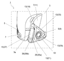
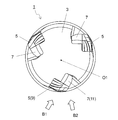
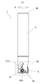
- FIG. 3 is a perspective view showing a non-limiting one-sided rotary tool according to the present disclosure. It is the enlarged view which expanded the area
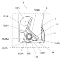
- FIG. 8 is an enlarged view in which a region A3 shown in FIG. 7 is enlarged.
- FIG. 5 is an enlarged view showing a non-limiting one-sided holder in the present disclosure.
- FIG. 5 is an enlarged view showing a non-limiting one-sided holder in the present disclosure.
- FIG. 5 is an enlarged view showing a non-limiting one-sided holder in the present disclosure.
- FIG. 5 is an enlarged view showing a non-limiting one-sided holder in the present disclosure.
- FIG. 5 is an enlarged view showing a non-limiting one-sided holder in the present disclosure.
- It is a schematic diagram showing one process of a manufacturing method of one side cutting thing which is not limited in this indication.
- It is a schematic diagram showing one process of a manufacturing method of one side cutting thing which is not limited in this indication.
- It is a schematic diagram showing one process of a manufacturing method of one side cutting thing which is not limited in this indication.
- the cutting tool may include a turning tool used for turning and a rotary tool used for rolling. Further, examples of the rotary tool may include a drill and a milling tool.
- FIG. 1 shows a milling tool 1 as an example of a cutting tool. However, the cutting tool is not limited to the milling tool 1.
- the rotary tool 1 (milling tool 1) of the non-limiting embodiment of the present disclosure may include a holder 3 and an insert 5 (cutting insert 5).
- the holder 3 may have a columnar shape extending from the first end 3a to the second end 3b along the rotation axis O1.
- the first end 3a may be restated as the leading end, and the second end 3b may be restated as the rear end.
- the rotary tool 1 can rotate around a rotation axis O1.
- the arrow X in FIG. 1 and the like indicates the rotation direction of the rotary tool 1.
- the material of the holder 3 may include steel and cast iron. In particular, from the viewpoint of enhancing the toughness of the holder 3, steel may be used among these materials.
- the holder 3 may have one or more pockets 7 located at the first end 3a.
- the number of pockets 7 is not particularly limited, and may be only one or plural.
- the holder 3 in the non-limiting example shown in FIG. 3 has three pockets 7.
- the holder 3 need not have a strict cylindrical shape, as will be clear from the fact that it can have pockets 7 and the like.
- the holder 3 may have a plurality of pockets 7, and the insert 5 may be located in each of these pockets 7.
- Each insert 5 may be located on the side of the first end 3 a of the rotary tool 1, as in a non-limiting example shown in FIG. 3.
- the pocket 7 is a portion to which the insert 5 is attached, and may be opened to the end surface located at the first end 3 a of the holder 3 and the outer peripheral surface 13.
- the rotary tool 1 may have three inserts 5, as the holder 3 has three pockets 7.
- the insert 5 may be in direct contact with the pocket 7, or a sheet may be sandwiched between the insert 5 and the pocket 7.
- the insert 5 may be brazed to the holder 3 or may be removable.
- these inserts 5 may have the same shape or different shapes.
- the pockets 7 may have the same shape or different shapes.
- a material having a hardness higher than that of the holder 3 is generally used.
- cemented carbide and cermet can be used as the material of the insert 5.
- the composition of the cemented carbide may include, for example, WC-Co, WC-TiC-Co and WC-TiC-TaC-Co.
- WC, TiC, and TaC are hard particles
- Co is a binder phase.
- cermet is a sintered composite material in which a metal is combined with a ceramic component.
- a titanium compound containing titanium carbide (TiC) or titanium nitride (TiN) as a main component may be mentioned.
- TiC titanium carbide
- TiN titanium nitride
- the material of the first insert 91 is not limited to the above composition.
- the surface of the insert 5 may be coated with a film using a chemical vapor deposition (CVD) method or a physical vapor deposition (PVD) method.
- the coating composition may include titanium carbide (TiC), titanium nitride (TiN), titanium carbonitride (TiCN), alumina (Al 2 O 3 ), and the like.
- first insert 9 One of the inserts 5 included in the rotary tool 1 is referred to as a first insert 9. Further, among the plurality of pockets 7, the pocket 7 in which the first insert 9 is located is referred to as a first pocket 11.
- the first insert 9 in the non-limiting embodiment of the present disclosure may have an outer peripheral surface 13, a first surface 15 and a second surface 17.
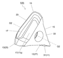
- the outer peripheral surface 13 may have a polygonal shape having a plurality of corners and a plurality of sides, as shown in FIG. 10.
- the outer peripheral surface 13 in the non-limiting example shown in FIG. 10 may be a substantially triangular shape having three corners and three sides.
- the three corners and the three sides of the outer peripheral surface 13 may be positioned so as to have a rotational symmetry of 120° with respect to the center of the outer peripheral surface 13 when the outer peripheral surface 13 is viewed from the front.
- the polygonal shape is not limited to a strictly polygonal shape.
- the three sides of the first surface 15 do not have to be strict straight lines.
- the center of the outer peripheral surface 13 can be specified by, for example, the position of the center of gravity of the outer peripheral surface 13 in front view.
- the outer peripheral surface 13 in the non-limiting example shown in FIG. 10 may have a first corner 19, a first side 21, and a second side 23.
- the first side 21 and the second side 23 may each extend from the first corner 19.
- the first corner 19 may be located between the first side 21 and the second side 23.
- the second side 23 may be located behind the first side 21 in the rotation direction X of the rotation axis O1.
- the first surface 15 and the second surface 17 may be adjacent to the outer peripheral surface 13, respectively.
- the first surface 15 may be connected to the first side 21.
- the second surface 17 may be connected to the second side 23. When the first side 21 and the second side 23 extend from the first corner 19, respectively, the first surface 15 and the second surface 17 may intersect with each other.
- the outer peripheral surface 13 may further include a second corner 25, a third corner 27, and a third side 29, as in a non-limiting example shown in FIG. 10.
- the third side 29 may be connected to the first side 21 on the side opposite to the second side 23.
- the third corner 27 may be located between the first side 21 and the third side 29.
- the third side 29 may be connected to the second side 23 on the side opposite to the first side 21 when the outer peripheral surface 13 has a substantially triangular shape as in a non-limiting example shown in FIG. 10.
- the second corner 25 may be located between the second side 23 and the third side 29.
- the first insert 9 may further have a third surface 31 connected to the third side 29.
- the third surface 31 may intersect with each of the first surface 15 and the second surface 17.
- the first insert 9 may further have an inner peripheral surface 33 located on the opposite side of the outer peripheral surface 13.
- the inner peripheral surface 33 may be parallel to the outer peripheral surface 13.
- the inner peripheral surface 33 may have a polygonal shape having a plurality of corners and a plurality of sides similarly to the outer peripheral surface 13.
- the inner peripheral surface 33 may have the same shape as the outer peripheral surface 13.
- the first insert 9 may have a polygonal plate shape.
- the first surface 15, the second surface 17, and the third surface 31 in the non-limiting example shown in FIGS. 10 and 11 may be located between the outer peripheral surface 13 and the inner peripheral surface 33, respectively. Further, the inner peripheral surface 33 may contact the first pocket 11.
- outer peripheral surface 13 and the inner peripheral surface 33 are not limited to the above shapes. In the non-limiting example shown in FIGS. 10 and 11, the outer peripheral surface 13 and the inner peripheral surface 33 are substantially triangular. However, the outer peripheral surface 13 and the inner peripheral surface 33 may be, for example, quadrangular, pentagonal, hexagonal, or octagonal, respectively.
- the maximum width when the outer peripheral surface 13 is viewed from the front may be, for example, 6 mm or more and 25 mm or less.
- the height from the outer peripheral surface 13 to the inner peripheral surface 33 may be, for example, 1 mm or more and 10 mm or less.
- the height from the outer peripheral surface 13 to the inner peripheral surface 33 may mean the maximum value of the interval in the direction parallel to the central axis passing through the center of the outer peripheral surface 13 and the center of the inner peripheral surface 33.
- the first insert 9 in the non-limiting embodiment of the present disclosure may have a cutting edge 35.
- the cutting edge 35 may have a role of cutting the work material at the time of cutting the work material for manufacturing a cut product.
- the cutting edge 35 in the non-limiting example illustrated in FIG. 10 may include a first cutting edge 35a.
- the first cutting edge 35a may be located on the first side 21.
- the first cutting edge 35a does not have to be located on the entire first side 21, and may be only a part of the first side 21.
- At least a part of the first cutting edge 35a may be located farther from the rotation axis O1 than the outer circumference of the holder 3. In other words, at least a part of the first cutting edge 35a may be located outside the outer circumference of the holder 3.
- the cutting edge 35 may further have a second cutting edge 35b as shown in FIG.
- the non-limiting example second cutting edge 35b illustrated in FIG. 10 may be located at the intersection of the first surface 15 and the third surface 31.
- the second cutting edge 35b does not have to be located at the entire intersection, and may be only a part of the intersection.
- At least a part of the second cutting edge 35b may be located farther from the second end 3b than the end surface of the holder 3 located at the first end 3a. In other words, at least a part of the second cutting edge 35b may protrude from the holder 3.
- the first cutting edge 35a can function as a so-called outer peripheral cutting edge.
- the second cutting edge 35b can function as a so-called bottom blade.
- the first surface 15 may have a rake face area 37 including an area along the first cutting edge 35a and the second cutting edge 35b.
- the rake face area 37 can function as a rake face with which chips come into contact when cutting is performed using the first cutting edge 35a and the second cutting edge 35b.
- the rake face region 37 may be the entire first face 15, or may be only a part of the first face 15 including the region along the first cutting edge 35a and the second cutting edge 35b. ..
- the outer peripheral surface 13 may have a first flank surface area 39 including an area along the first cutting edge 35a. Further, the third surface 31 may have a second flank surface area 41 including an area along the second cutting edge 35b.
- the first flank surface region 39 and the second flank surface region 41 can function as flank surfaces when performing cutting using the first cutting edge 35a and the second cutting edge 35b.
- the first flank surface region 39 may be the entire outer peripheral surface 13, and the second flank surface region 41 may be the entire third surface 31.
- the second surface 17 When the second side 23 is located behind the first side 21 in the rotation direction X, the second surface 17 may be located behind the first surface 15 in the rotation direction X. The second surface 17 may abut the pocket 7. When the second surface 17 comes into contact with the pocket 7, the main component force generated when the cutting process is performed using the first cutting edge 35 a is mainly transferred from the first insert 9 to the holder 3 on the second surface 17. Easy to communicate.
- the second surface 17 may have a flat portion 17a.
- the flat portion 17a can function as a surface that contacts the pocket 7.
- the pocket 7 may have a concave portion 43 that is recessed when viewed from the side.
- the recess 43 may be located at a position facing the second surface 17. Specifically, the recess 43 may face the flat portion 17a.
- the recess 43 in the non-limiting embodiment of the present disclosure may have a bottom 45, a first region 47 and a second region 49.
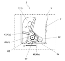
- the first region 47 may be located in front of the bottom portion 45 in the rotation direction X and may be inclined with respect to the flat portion 17a when viewed from the side. Therefore, the first region 47 may approach the second surface 17 as it moves away from the bottom portion 45.
- the second region 49 may be located rearward of the bottom portion 45 in the rotation direction X and may be inclined with respect to the flat portion 17a when viewed from the side. Therefore, the second region 49 may approach the second surface 17 as it moves away from the bottom portion 45.
- the recess 43 in the non-limiting embodiment of the present disclosure may abut the first insert 9.
- the first region 47 and the second region 49 may abut the first insert 9.
- the first region 47 may have the first portion 47a that abuts the flat portion 17a.
- the second region 49 may have a second portion 49a that abuts the flat portion 17a.
- the bottom portion 45 may be separated from the first insert 9 while the first region 47 and the second region 49 contact the first insert 9.
- the first portion 47a and the second portion 49a are located apart from each other with the bottom portion 45 interposed therebetween, and the bottom portion 45 is separated from the first insert 9. Therefore, the first portion 47a and the second portion 49a are likely to stably come into contact with the first insert 9. As a result, the first insert 9 is likely to be stably held by the holder 3.
- the first region 47 and the second region 49 may approach the second surface 17 as they move away from the bottom 45. Therefore, the first region 47 may be inclined with respect to the second region 49.
- the angle ⁇ 0 at which the first imaginary line L1 extending the first region 47 and the second imaginary line L2 extending the second region 49 intersect may be an obtuse angle.
- the above main component force is mainly transmitted from the second surface 17 to the first region 47 and the second region 49.
- the angle ⁇ 0 is an obtuse angle, it is difficult for the load to concentrate on the bottom portion 45 located between the first region 47 and the second region 49. Therefore, the recess 43 is less likely to be cracked. Therefore, the durability of the holder 3 is high.
- the angle ⁇ 0 can be set to, for example, 160° to 179.95°.
- the first insert 9 may further have a through hole 51 that opens in the outer peripheral surface 13, as shown in FIG. 10.
- the through hole 51 in the non-limiting example shown in FIGS. 10 and 11 may be formed from the center of the outer peripheral surface 13 toward the center of the inner peripheral surface 33. At this time, the through hole 51 may be opened in the inner peripheral surface 33. Further, when the through hole 51 in the non-limiting example shown in FIGS. 10 and 11 is formed from the center of the outer peripheral surface 13 toward the center of the inner peripheral surface 33, as in the non-limiting example shown in FIG.
- the central axis O2 of the hole 51 may coincide with the central axis of the first insert 9.
- the through hole 51 can be used for inserting, for example, a screw 53 when fixing the first insert 9 to the holder 3.
- the screw 53 is inserted into the through hole 51 of the first insert 9, the tip of the screw 53 is inserted into the screw hole formed in the pocket 7, and the screw 53 is fixed to the screw hole. It may be attached to the holder 3.
- the through hole 51 in the non-limiting example shown in FIGS. 10 and 11 is formed from the center of the outer peripheral surface 13 toward the center of the inner peripheral surface 33, but the through hole 51 is not limited to such a configuration.
- the first insert 9 When the first insert 9 has the through hole 51, at least a part of the first portion 47a may be located forward of the central axis O2 of the through hole 51 in the rotation direction X.
- the main component force is hard to be applied to the screw 53. In other words, it is easy to stably and stably receive the above main component force at the first portion 47a. Therefore, the durability of the screw 53 is high.
- At least a part of the second portion 49a may be located closer to the first end 3a side than the central axis O2 of the through hole 51.
- the second portion 49a when the second portion 49a is positioned as described above, it is easy to stably and stably receive the main component force described above at the second portion 49a. Therefore, the main component force is hard to be applied to the screw 53, and the durability of the screw 53 is high.
- the first area 47 and the second area 49 may be flat, in other words, flat.
- the first area 47 and the second area 49 may be curved surfaces.
- the first area 47 and the second area 49 may be convex curved surfaces as shown in FIG. 12, or may be concave as shown in FIG. It may be a curved surface.
- the first region 47 and the second region 49 may have a configuration in which a flat surface portion, a convex curved surface portion and a concave curved surface portion are combined.
- the first region 47 and the second region 49 may have a configuration in which convex curved surface portions and concave curved surface portions are combined.
- FIG. 12 is an enlarged view showing one holder 3 of a non-limiting embodiment of the present disclosure, and is a drawing corresponding to FIG. 9.
- FIG. 13 is an enlarged view showing one holder 3 of a non-limiting embodiment of the present disclosure, and is a drawing corresponding to FIG. 9.
- FIG. 14 is an enlarged view showing one holder 3 according to a non-limiting embodiment of the present disclosure, and is a drawing corresponding to FIG. 9.
- the durability of the first region 47 is high.
- the main component force is hard to concentrate on a part of the second region 49. Therefore, the durability of the second region 49 is high.
- the first region 47 has a convex curved surface shape
- the second region 49 has a convex curved surface shape
- the first region 47 has a convex curved surface shape
- the second region 49 has a convex curved surface shape, even if the pocket 7 is slightly deformed, it is easy to stably receive the main component force at the second portion 49a. Therefore, the durability of the second portion 49a is high.
- the non-limiting example outer peripheral surface 13 shown in FIG. 2 may have the first corner 19 and the second corner 25 adjacent to the second side 23, as described above. When viewed from the side, the first corner 19 and the second corner 25 may be separated from the recess 43, respectively.
- the first portion 47a When the first corner 19 is separated from the recess 43, the first portion 47a may be located apart from the first corner 19. At this time, chipping is less likely to occur in the vicinity of the first corner 19 when the main component force is received by the first portion 47a.
- the second portion 49 a when the second corner 25 is separated from the recess 43, the second portion 49 a may be located apart from the second corner 25. At this time, when the main component force is received by the second portion 49a, chipping is unlikely to occur near the second corner 25.
- the inclination angle of the first region 47 with respect to the flat portion 17a is the first angle ⁇ 1.
- the inclination angle of the second region 49 with respect to the flat portion 17a is a second angle ⁇ 2 when viewed from the side.
- the second angle ⁇ 2 may be larger than the first angle ⁇ 1.
- a large angle ⁇ 0 at which the first imaginary line L1 and the second imaginary line L2 intersect is ensured, and the main component force is stabilized in the second portion 49a. Easy to catch.
- the above configuration is effective when a relatively large cutting load is applied to a portion of the first cutting edge 35a near the first end 3a of the holder 3.
- FIG. 15 is an enlarged view showing one holder 3 of the non-limiting embodiment of the present disclosure, and is a drawing corresponding to FIG. 8.
- the first angle ⁇ 1 may be the same as the second angle ⁇ 2.
- the first angle ⁇ 1 is the same as the second angle ⁇ 2, it is easy to stably receive the main component force in each of the first portion 47a and the second portion 49a.
- the above configuration is effective when a large cutting load is likely to be applied not only to the portion of the first cutting edge 35a close to the first end 3a of the holder 3 but also to the portion away from the first end 3a.
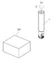
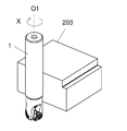
- FIGS. 16 to 18 show a method for manufacturing a machined product when the rotary tool 1 is used for machining. 16 to 18, the rotary shaft of the rotary tool 1 is shown by a chain double-dashed line.
- the cutting work 203 can be produced by cutting the work material 201.
- the method for manufacturing a cut product may include the following steps.
- the rotary tool 1 may be brought relatively close to the work material 201 while rotating in the X direction around the rotation axis O1.
- the cutting blade of the rotary tool 1 may be brought into contact with the work material 201 to cut the work material 201.
- the rotary tool 1 may be relatively separated from the work material 201.
- the work material 201 may be fixed and the rotary tool 1 may be brought closer. 16 to 18, the work material 201 may be fixed and the rotary tool 1 may be rotated around the rotation axis O1. 18, the work material 201 may be fixed and the rotary tool 1 may be moved away. In the above-described cutting process, the work material 201 is fixed and the rotary tool 1 is moved in each step, but of course the invention is not limited to such a form.
- the work material 201 may be brought close to the rotary tool 1.
- the work material 201 may be moved away from the rotary tool 1.
- the step of keeping the rotating tool 1 rotated and bringing the cutting edge of the insert into contact with different parts of the work material 201 may be repeated.
Landscapes
- Engineering & Computer Science (AREA)
- Mechanical Engineering (AREA)
- Milling Processes (AREA)
Abstract
一態様の回転工具は、ホルダ及びインサートを有する。ホルダはポケットを有する。インサートは、外周面、第1面、第2面及び切刃を有する。外周面は、第1辺及び第2辺を有する。第2辺は、第1辺よりも回転軸の回転方向の後方に位置する。第2面は、第2辺に接続される。切刃は、第1辺に位置する。ポケットは、第2面に対向する箇所に位置する凹部を有する。凹部は、底部、第1領域及び第2領域を有する。第1領域は、底部よりも回転方向の前方に位置する。第2領域は、底部よりも回転方向の後方に位置する。第1領域は、第2面に当接する第1部位を有する。第2領域は、第2面に当接する第2部位を有する。底部は、第2面から離れる。
Description
本出願は、2018年12月25日に出願された日本国特許出願2018-241817号の優先権を主張するものであり、この先の出願の開示全体を、ここに参照のために取り込む。
本態様は、一般的には、被削材の切削加工に用いられる切削工具及び切削加工物の製造方法に関する。具体的には、フライス加工などの転削加工に用いられる回転工具に関する。
金属などの被削材を切削加工する際に用いられる切削工具として、例えば特開2014-046436号公報(特許文献1)及び国際公開第2012/104832号(特許文献2)に記載のフライス工具が知られる。特許文献1及び2に記載の各フライス工具は、切削インサートと、切削インサートが保持されるポケットと、を有する。なお、以下の記載において、切削インサートは、単にインサートと言い換えてもよい。
例えば特許文献2に記載のインサートは、接触面78、80を有する。また、ポケットは、インサートに対して回転方向の後方にそれぞれ位置する、位置決め面66、68と、中央領域70とを有する。ポケットにおける位置決め面66、68及び中央領域70によって構成される部分は、側面視した場合に、全体として凸形状である。
特許文献2に記載のフライス工具のように、インサートに対して回転方向の後方に位置する面が、側面視した場合に全体として凸形状である場合には、位置決め面66、68の両方を接触面に接触させることが困難となり、例えば、接触面80が位置決め面68から離れてしまう恐れがある。この原因として、ポケットの製造誤差、或いは、切削加工の繰り返しによるポケットの変形などが考えられる。また、インサート及びポケットの製造誤差に起因して、位置決め面66を接触面80に面接触させることが困難であった。
接触面80が位置決め面68から離れてしまう、或いは、位置決め面66を接触面80に面接触させることが困難であることによって、ポケットにおけるインサートの保持が不安定となる恐れがある。
本開示における限定されない一面の回転工具は、ホルダと、インサートとを有する。ホルダは、回転軸に沿って第1端から第2端にかけて延びた円柱形状であって、第1端に位置するポケットを有する。インサートは、ポケットに位置する。インサートは、外周面と、第1面と、第2面と、切刃とを有する。外周面は、多角形状であって、ホルダの外周側に位置し、第1辺及び第2辺を有する。第2辺は、第1辺よりも回転軸の回転方向の後方に位置する。第1面は、第1辺に接続されている。第2面は、第2辺に接続されている。切刃は、第1辺に位置する。
第2面は、平らな部位を有する。ポケットは、第2面に対向する箇所に位置し、側面視した場合に窪んだ形状である凹部を有する。凹部は、底部と、第1領域と、第2領域とを有する。第1領域は、底部よりも回転方向の前方に位置し、側面視した場合に平らな部位に対して傾斜する。第2領域は、底部よりも回転方向の後方に位置し、側面視した場合に平らな部位に対して傾斜する。第1領域は、第2面に当接する第1部位を有する。第2領域は、第2面に当接する第2部位を有する。底部は、第2面から離れる。
以下、本開示の限定されない実施形態の切削工具について、それぞれ図面を用いて詳細に説明する。但し、以下で参照する各図では、説明の便宜上、各実施形態を説明する上で必要な主要部材のみが簡略化して示される。したがって、以下に開示する切削工具は、参照する各図に示されていない任意の構成部材を備え得る。また、各図中の部材の寸法は、実際の構成部材の寸法及び各部材の寸法比率等を忠実に表したものではない。
切削工具としては、旋削加工に用いられる旋削工具及び転削加工に用いられる回転工具などが挙げられ得る。また、回転工具としては、例えば、ドリル及びフライス工具などが挙げられ得る。図1には、切削工具の一例としてフライス工具1が示される。ただし、切削工具は、フライス工具1には限定されない。
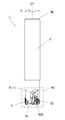
本開示の限定されない実施形態の回転工具1(フライス工具1)は、ホルダ3と、インサート5(切削インサート5)とを有してもよい。ホルダ3は、回転軸O1に沿って第1端3aから第2端3bにかけて延びた円柱形状であってもよい。第1端3aを先端と言い換えてもよく、また、第2端3bを後端と言い換えてもよい。切削加工物を製造するために被削材を切削する工程において、回転工具1は、回転軸O1の周りで回転可能である。なお、図1などにおける矢印Xは、回転工具1の回転方向である。
ホルダ3の材質としては、鋼及び鋳鉄などが挙げられ得る。特に、ホルダ3の靭性を高める観点から、これらの材質の中で鋼を用いてもよい。
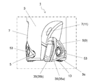
ホルダ3は、第1端3aに位置する1つ以上のポケット7を有してもよい。ポケット7の数は、特に限定されず、1つのみであってもよく、また、複数であってもよい。図3に示す限定されない一例におけるホルダ3は、3つのポケット7を有する。ホルダ3は、ポケット7を有し得ることなどから明らかであるように、厳密な円柱形状でなくてもよい。
ホルダ3が複数のポケット7を有し、これらのポケット7にそれぞれインサート5が位置してもよい。図3に示す限定されない一例のように、各インサート5が回転工具1における第1端3aの側に位置してもよい。
ポケット7は、インサート5が装着される部分であり、ホルダ3の第1端3aに位置する端面及び外周面13に対して開口してもよい。図3に示す限定されない一例においては、ホルダ3が3つのポケット7を有することから、回転工具1が3つのインサート5を有してもよい。インサート5はポケット7に直接に接してもよく、また、インサート5及びポケット7の間にシートが挟まれてもよい。インサート5は、ホルダ3に対してロウ付けされてもよく、また、着脱可能であってもよい。
回転工具1が複数のインサート5を有する場合には、これらのインサート5は互いに同じ形状であっても、また、互いに異なる形状であってもよい。また、ホルダ3が複数のポケット7を有する場合には、これらのポケット7は互いに同じ形状であっても、また、互いに異なる形状であってもよい。
インサート5の材質は、一般的に、ホルダ3よりも高い硬度の材質が用いられる。具体的には、例えば、超硬合金及びサーメットなどがインサート5の材質として挙げられ得る。超硬合金の組成としては、例えば、WC-Co、WC-TiC-Co及びWC-TiC-TaC-Coが挙げられ得る。ここで、WC、TiC及びTaCは硬質粒子であり、Coは結合相である。
また、サーメットは、セラミック成分に金属を複合させた焼結複合材料である。サーメットの一例として、炭化チタン(TiC)又は窒化チタン(TiN)を主成分としたチタン化合物が挙げられ得る。ただし、第1インサート91の材質が上記の組成に限定されないことは言うまでもない。
インサート5の表面は、化学蒸着(CVD)法、又は物理蒸着(PVD)法を用いて被膜でコーティングされてもよい。被膜の組成としては、炭化チタン(TiC)、窒化チタン(TiN)、炭窒化チタン(TiCN)及びアルミナ(Al2O3)などが挙げられ得る。
回転工具1が有する複数のインサート5の1つを、第1インサート9とする。また、複数のポケット7のうち、第1インサート9が位置するポケット7を第1ポケット11とする。
本開示の限定されない実施形態における第1インサート9は、外周面13、第1面15及び第2面17を有してもよい。外周面13は、図10に示すように、複数の角及び複数の辺を有する多角形状であってもよい。図10に示す限定されない一例における外周面13は、3つの角及び3つの辺を有する略三角形であってもよい。
外周面13における3つの角及び3つの辺は、外周面13を正面視した場合において、外周面13の中心を基準として120°の回転対称となるように位置してもよい。なお、多角形状とは、厳密に多角形の形状であることに限定されない。例えば、第1面15における3つの辺は、それぞれ厳密な直線でなくてもよい。また、外周面13の中心は、例えば、外周面13の正面視における外周面13の重心位置によって特定することが可能である。
図10に示す限定されない一例における外周面13は、第1角19、第1辺21及び第2辺23を有してもよい。第1辺21及び第2辺23は、それぞれ第1角19から延びてもよい。言い換えれば、第1角19は、第1辺21及び第2辺23の間に位置してもよい。第2辺23は、第1辺21よりも回転軸O1の回転方向Xの後方に位置してもよい。
第1面15及び第2面17は、それぞれ外周面13と隣り合ってもよい。第1面15は、第1辺21に接続されてもよい。第2面17は、第2辺23に接続されてもよい。第1辺21及び第2辺23が第1角19からそれぞれ延びる場合には、第1面15及び第2面17が互いに交わってもよい。
外周面13は、図10に示す限定されない一例のように、第2角25、第3角27及び第3辺29をさらに有してもよい。第3辺29は、第2辺23とは反対側において第1辺21に繋がってもよい。第3角27は、第1辺21及び第3辺29の間に位置してもよい。図10に示す限定されない一例のように外周面13が略三角形である場合に、第3辺29が、第1辺21とは反対側において第2辺23に繋がってもよい。第2角25は、第2辺23及び第3辺29の間に位置してもよい。
第1インサート9は、第3辺29に接続された第3面31をさらに有してもよい。第3面31は、第1面15及び第2面17のそれぞれに対して交わってもよい。また、第1インサート9は、外周面13の反対側に位置する内周面33をさらに有してもよい。内周面33は、外周面13に対して平行であってもよい。内周面33は、外周面13と同様に複数の角及び複数の辺を有する多角形状であってもよい。
このとき、内周面33が、外周面13と同じ形状であってもよい。図10及び図11に示す限定されない一例のように第1インサート9が多角形状の外周面13及び内周面33を有する場合には、第1インサート9が多角板形状であってもよい。図10及び図11に示す限定されない一例における第1面15、第2面17及び第3面31は、それぞれ外周面13及び内周面33の間に位置してもよい。また、内周面33は、第1ポケット11に当接してもよい。
外周面13及び内周面33は、上記の形状に限定されない。図10及び図11に示す限定されない一例においては、外周面13及び内周面33が略三角形である。しかしながら、外周面13及び内周面33が、例えば、それぞれ四角形、五角形、六角形又は八角形であってもよい。
外周面13を正面視した場合における最大幅は、例えば6mm以上25mm以下であってもよい。また、外周面13から内周面33までの高さは、例えば1mm以上10mm以下であってもよい。ここで、外周面13から内周面33までの高さとは、外周面13の中心及び内周面33の中心を通る中心軸に平行な方向での間隔の最大値を意味してもよい。
本開示の限定されない実施形態における第1インサート9は、切刃35を有してもよい。切刃35は、切削加工物を製造するための被削材の切削加工時において、被削材を切削する役割を有してもよい。図10に示す限定されない一例における切刃35は、第1切刃35aを有してもよい。第1切刃35aは、第1辺21に位置してもよい。なお、第1切刃35aは、第1辺21の全体に位置する必要はなく、第1辺21の一部のみであってもよい。
第1切刃35aの少なくとも一部は、ホルダ3の外周よりも回転軸O1から離れて位置してもよい。言い換えれば、第1切刃35aの少なくとも一部は、ホルダ3の外周よりも外方に位置してもよい。
切刃35は、図10に示すように第2切刃35bをさらに有してもよい。図10に示す限定されない一例の第2切刃35bは、第1面15及び第3面31の交わりに位置してもよい。なお、第2切刃35bは、上記の交わりの全体に位置する必要はなく、この交わりの一部のみであってもよい。
第2切刃35bの少なくとも一部は、ホルダ3の第1端3aに位置する端面よりも第2端3bから離れて位置してもよい。言い換えれば、第2切刃35bの少なくとも一部は、ホルダ3から突出してもよい。
本開示の限定されない実施形態の回転工具1においては、第1切刃35aは、いわゆる外周切刃として機能することが可能である。また、第2切刃35bは、いわゆる底刃として機能することが可能である。
第1面15は、第1切刃35a及び第2切刃35bに沿った領域を含むすくい面領域37を有してもよい。すくい面領域37は、第1切刃35a及び第2切刃35bを用いて切削加工を行う際に、切屑が接触するすくい面として機能することが可能である。すくい面領域37は、第1面15の全体であってもよく、また、第1面15における第1切刃35a及び第2切刃35bに沿った領域を含む一部のみであってもよい。
外周面13は、第1切刃35aに沿った領域を含む第1逃げ面領域39を有してもよい。また、第3面31は、第2切刃35bに沿った領域を含む第2逃げ面領域41を有してもよい。第1逃げ面領域39及び第2逃げ面領域41は、第1切刃35a及び第2切刃35bを用いて切削加工を行う際に、逃げ面として機能することが可能である。第1逃げ面領域39は、外周面13の全体であってもよく、また、第2逃げ面領域41は、第3面31の全体であってもよい。
第2辺23が第1辺21よりも回転方向Xの後方に位置する場合には、第2面17は第1面15よりも回転方向Xの後方に位置してもよい。第2面17は、ポケット7に当接してもよい。第2面17がポケット7に当接する場合には、第1切刃35aを用いて切削加工を行う際に生じる主分力が、主に第2面17において第1インサート9からホルダ3へと伝わり易い。
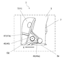
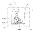
第2面17は、平らな部位17aを有してもよい。この平らな部位17aはポケット7に当接する面として機能することが可能である。ポケット7は、側面視した場合に窪んだ形状である凹部43を有してもよい。凹部43は、第2面17に対向する箇所に位置してもよい。具体的には、凹部43は、上記の平らな部位17aに対向してもよい。凹部43が第2面17に対向する場合には、上記の主分力が、主に第2面17から凹部43へと伝わり易い。
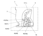
本開示の限定されない実施形態における凹部43は、底部45、第1領域47及び第2領域49を有してもよい。第1領域47は、底部45よりも回転方向Xの前方に位置し、側面視した場合に上記の平らな部位17aに対して傾斜してもよい。そのため、第1領域47は、底部45から離れるにしたがって第2面17に近づいてもよい。第2領域49は、底部45よりも回転方向Xの後方に位置し、側面視した場合に平らな部位17aに対して傾斜してもよい。そのため、第2領域49は、底部45から離れるにしたがって第2面17に近づいてもよい。
本開示の限定されない実施形態における凹部43は、第1インサート9に当接してもよい。このとき、第1領域47及び第2領域49が第1インサート9に当接してもよい。言い換えれば、第1領域47は、平らな部位17aに当接する第1部位47aを有してもよい。第2領域49は、平らな部位17aに当接する第2部位49aを有してもよい。第1領域47及び第2領域49が第1インサート9に当接する一方で、底部45が第1インサート9から離れてもよい。
第1インサート9及びポケット7が上記の構成である場合には、ポケット7の製造誤差、或いは、切削加工の繰り返しによるポケット7の変形などが生じたとしても、第1部位47a及び第2部位49aの2箇所が第1インサート9に当接し易い。第1部位47a及び第2部位49aが底部45を間に介して互いに離れて位置しており、且つ、底部45が第1インサート9から離れている。そのため、第1部位47a及び第2部位49aが安定して第1インサート9に当接し易い。結果として、第1インサート9が、ホルダ3に安定して保持され易い。
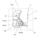
凹部43を側面視した場合において、第1領域47及び第2領域49は、それぞれ底部45から離れるにしたがって第2面17に近づいてもよい。そのため、第1領域47は、第2領域49に対して傾斜してもよい。ここで、側面視した場合に、第1領域47を引き延ばした第1仮想線L1及び第2領域49を引き延ばした第2仮想線L2の交わる角度θ0が、鈍角であってもよい。
切削加工時に、上記の主分力が、主に第2面17から第1領域47及び第2領域49へと伝わる。上記の角度θ0が鈍角である場合には、第1領域47及び第2領域49の間に位置する底部45に負荷が集中しにくい。そのため、凹部43にクラックが生じにくい。従って、ホルダ3の耐久性が高い。角度θ0は、例えば、160°~179.95°に設定できる。
第1インサート9は、図10に示すように、外周面13において開口する貫通孔51をさらに有してもよい。なお、図10及び図11に示す限定されない一例における貫通孔51は、外周面13の中心から内周面33の中心に向かって形成されてもよい。このとき、貫通孔51は、内周面33において開口してもよい。また、図10及び図11に示す限定されない一例における貫通孔51が外周面13の中心から内周面33の中心に向かって形成される場合に、図10に示す限定されない一例のように、貫通孔51の中心軸O2が第1インサート9の中心軸と一致してもよい。
貫通孔51は、第1インサート9をホルダ3に固定する際に例えばネジ53を挿入するために用いることが可能である。第1インサート9の貫通孔51にネジ53を挿入し、このネジ53の先端をポケット7に形成されたネジ孔に挿入して、ネジ53をネジ孔に固定させることによって、第1インサート9をホルダ3に装着してもよい。
第1インサート9をホルダ3に固定する際には、ネジ53の代わりに例えばクランプ部材を用いてもよい。図10及び図11に示す限定されない一例における貫通孔51は、外周面13の中心から内周面33の中心に向かって形成されているが、貫通孔51はこのような構成に限定されない。
また、第1インサート9が上記の貫通孔51を有する場合において、第1部位47aの少なくとも一部が、貫通孔51の中心軸O2よりも回転方向Xの前方に位置してもよい。この場合には、上記の主分力がネジ53に加わりにくい。言い換えれば、上記の主分力を第1部位47aにおいて安定して受け止め易い。そのため、ネジ53の耐久性が高い。
また、第1インサート9が上記の貫通孔51を有する場合において、第2部位49aの少なくとも一部が、貫通孔51の中心軸O2よりも第1端3aの側に位置してもよい。第1切刃35aを用いて切削加工を行う際に、第1切刃35aのうち、ホルダ3の第1端3aに近い部分に相対的に大きな切削負荷が加わり易い。
そのため、第2部位49aが上記のように位置する場合には、上記の主分力を第2部位49aにおいて安定して受け止め易い。従って、上記の主分力がネジ53に加わりにくく、ネジ53の耐久性が高い。
第1領域47及び第2領域49は、それぞれ平らである、言い換えれば平面であってもよい。また、第1領域47及び第2領域49は、曲面であってもよい。第1領域47及び第2領域49が曲面である場合に、第1領域47及び第2領域49は、図12に示すように凸曲面であってもよく、また、図13に示すように凹曲面であってもよい。また、第1領域47及び第2領域49は、平面部分、凸曲面部分及び凹曲面部分を組み合わせた構成であってもよい。例えば、図14に示すように、第1領域47及び第2領域49は、凸曲面部分及び凹曲面部分を組み合わせた構成であってもよい。
なお、図12は、本開示の限定されない実施形態の一つのホルダ3を示す拡大図であって、図9に対応する図面である。図13は、本開示の限定されない実施形態の一つのホルダ3を示す拡大図であって、図9に対応する図面である。図14は、本開示の限定されない実施形態の一つのホルダ3を示す拡大図であって、図9に対応する図面である。
第1領域47が平らである場合には、上記の主分力が第1領域47における一部の箇所に集中しにくい。そのため、第1領域47の耐久性が高い。同様に、第2領域49が平らである場合には、上記の主分力が第2領域49における一部の箇所に集中しにくい。そのため、第2領域49の耐久性が高い。
また、第1領域47が凸曲面形状である場合には、ポケット7が若干変形した場合などにおいても、主分力を第1部位47aにおいて安定して受け止め易い。そのため、第1部位47aの耐久性が高い。同様に、第2領域49が凸曲面形状である場合には、ポケット7が若干変形した場合などにおいても、主分力を第2部位49aにおいて安定して受け止め易い。そのため、第2部位49aの耐久性が高い。
図2に示す限定されない一例の外周面13は、上記した通り、第2辺23と隣り合う第1角19及び第2角25を有してもよい。側面視した場合に、第1角19及び第2角25は、それぞれ凹部43から離れてもよい。
第1角19が凹部43から離れる場合には、第1部位47aが第1角19から離れて位置してもよい。このとき、第1部位47aにおいて上記の主分力を受け止める際に、第1角19の近傍においてチッピングが生じにくい。同様に、第2角25が凹部43から離れている場合には、第2部位49aが第2角25から離れて位置してもよい。このとき、第2部位49aにおいて上記の主分力を受け止める際に、第2角25の近傍においてチッピングが生じにくい。
側面視した場合に、平らな部位17aに対する第1領域47の傾斜角を第1角度θ1とする。また、側面視した場合に、平らな部位17aに対する第2領域49の傾斜角を第2角度θ2とする。
このとき、図15に示すように、第2角度θ2が第1角度θ1より大きくてもよい。第2角度θ2が第1角度θ1より大きい場合には、第1仮想線L1及び第2仮想線L2の交わる角度θ0を大きく確保しつつ、第2部位49aにおいて上記の主分力を安定して受け止め易い。第1切刃35aのうち、ホルダ3の第1端3aに近い部分に比較的大きな切削負荷が加わる場合には、上記の構成が有効である。なお、図15は、本開示の限定されない実施形態の一つのホルダ3を示す拡大図であって、図8に対応する図面である。
また、第1角度θ1が第2角度θ2と同じであってもよい。第1角度θ1が第2角度θ2と同じである場合には、第1部位47a及び第2部位49aのそれぞれにおいて上記の主分力を安定して受け止め易い。第1切刃35aのうち、ホルダ3の第1端3aに近い部分だけでなく第1端3aから離れた部分にも大きな切削負荷が加わり易い場合には、上記の構成が有効である。
<切削加工物の製造方法>
次に、本開示の限定されない実施形態の切削加工物の製造方法について図16~図18を用いて説明する。図16~図18は、上記の回転工具1を用いて切削加工を行った場合の切削加工物の製造方法を示す。図16~図18において、回転工具1の回転軸を二点鎖線で示す。切削加工物203は、被削材201を切削加工することによって作製され得る。切削加工物の製造方法は、以下の工程を備えてもよい。
次に、本開示の限定されない実施形態の切削加工物の製造方法について図16~図18を用いて説明する。図16~図18は、上記の回転工具1を用いて切削加工を行った場合の切削加工物の製造方法を示す。図16~図18において、回転工具1の回転軸を二点鎖線で示す。切削加工物203は、被削材201を切削加工することによって作製され得る。切削加工物の製造方法は、以下の工程を備えてもよい。
すなわち、
(1)上記の実施形態に代表される回転工具1を回転させる工程と、
(2)回転している回転工具1を被削材201に接触させる工程と、
(3)回転工具1を被削材201から離す工程と、
を備えてもよい。
(1)上記の実施形態に代表される回転工具1を回転させる工程と、
(2)回転している回転工具1を被削材201に接触させる工程と、
(3)回転工具1を被削材201から離す工程と、
を備えてもよい。
より具体的には、まず、図16に示すように、回転工具1を回転軸O1の周りでX方向に回転させながら被削材201に相対的に近付けてもよい。次に、図17に示すように、回転工具1における切刃を被削材201に接触させて、被削材201を切削してもよい。そして、図18に示すように、回転工具1を被削材201から相対的に遠ざけてもよい。
実施形態においては、被削材201を固定するとともに回転工具1を近付けてもよい。また、図16~図18においては、被削材201を固定するとともに回転工具1を回転軸O1の周りで回転させてもよい。また、図18においては、被削材201を固定するとともに回転工具1を遠ざけてもよい。なお、上記した切削加工では、それぞれの工程において、被削材201を固定するとともに回転工具1を動かしているが、当然ながらこのような形態に限定されない。
例えば、(1)の工程において、被削材201を回転工具1に近付けてもよい。同様に、(3)の工程において、被削材201を回転工具1から遠ざけてもよい。切削加工を継続する場合には、回転工具1を回転させた状態を維持して、被削材201の異なる箇所にインサートの切刃を接触させる工程を繰り返せばよい。
被削材201の材質の代表例としては、炭素鋼、合金鋼、ステンレス、鋳鉄及び非鉄金属などが挙げられ得る。
1・・・回転工具(フライス工具)
3・・・ホルダ
3a・・第1端
3b・・第2端
O1・・・回転軸
X・・・回転方向
5・・・インサート
7・・・ポケット
9・・・第1インサート
11・・・第1ポケット
13・・・外周面
15・・・第1面
17・・・第2面
17a・・平らな部位
19・・・第1角
21・・・第1辺
23・・・第2辺
25・・・第2角
27・・・第3角
29・・・第3辺
31・・・第3面
33・・・内周面
35・・・切刃
35a・・第1切刃
35b・・第2切刃
37・・・すくい面領域
39・・・第1逃げ面領域
41・・・第2逃げ面領域
43・・・凹部
45・・・底部
47・・・第1領域
47a・・第1部位
49・・・第2領域
49a・・第2部位
L1・・・第1仮想線
L2・・・第2仮想線
θ0・・・角度
51・・・貫通孔
53・・・ネジ
θ1・・・第1角度
θ2・・・第2角度
201・・・被削材
203・・・切削加工物
3・・・ホルダ
3a・・第1端
3b・・第2端
O1・・・回転軸
X・・・回転方向
5・・・インサート
7・・・ポケット
9・・・第1インサート
11・・・第1ポケット
13・・・外周面
15・・・第1面
17・・・第2面
17a・・平らな部位
19・・・第1角
21・・・第1辺
23・・・第2辺
25・・・第2角
27・・・第3角
29・・・第3辺
31・・・第3面
33・・・内周面
35・・・切刃
35a・・第1切刃
35b・・第2切刃
37・・・すくい面領域
39・・・第1逃げ面領域
41・・・第2逃げ面領域
43・・・凹部
45・・・底部
47・・・第1領域
47a・・第1部位
49・・・第2領域
49a・・第2部位
L1・・・第1仮想線
L2・・・第2仮想線
θ0・・・角度
51・・・貫通孔
53・・・ネジ
θ1・・・第1角度
θ2・・・第2角度
201・・・被削材
203・・・切削加工物
Claims (10)
- 回転軸に沿って第1端から第2端にかけて延びた円柱形状であって、前記第1端に位置するポケットを有するホルダと、
前記ポケットに位置するインサートとを有し、
前記インサートは、
多角形状であって、前記ホルダの外周側に位置し、
第1辺と、
前記第1辺よりも前記回転軸の回転方向の後方に位置する第2辺とを有する外周面と、
前記第1辺に接続された第1面と、
前記第2辺に接続された第2面と、
前記第1辺に位置する切刃とを有し、
前記第2面は、平らな部位を有し、
前記ポケットは、前記第2面に対向する箇所に位置し、側面視した場合に窪んだ形状である凹部を有し、
前記凹部は、
底部と、
前記底部よりも前記回転方向の前方に位置し、側面視した場合に前記平らな部位に対して傾斜した第1領域と、
前記底部よりも前記回転方向の後方に位置し、側面視した場合に前記平らな部位に対して傾斜した第2領域とを有し、
前記第1領域は、前記第2面に当接する第1部位を有し、
前記第2領域は、前記第2面に当接する第2部位を有し、
前記底部は、前記第2面から離れている、回転工具。 - 側面視した場合に、前記第1領域を引き延ばした第1仮想線及び前記第2領域を引き延ばした第2仮想線の交わる角度が、鈍角である、請求項1に記載の回転工具。
- 前記インサートを前記ホルダに固定するネジをさらに有し、
前記インサートは、前記外周面において開口し、前記ネジが挿入された貫通孔をさらに有し、
前記第1部位の少なくとも一部が、前記貫通孔の中心軸よりも前記回転方向の前方に位置している、請求項1又は2に記載の回転工具。 - 前記インサートを前記ホルダに固定するネジをさらに有し、
前記インサートは、前記外周面において開口し、前記ネジが挿入された貫通孔をさらに有し、
前記第2部位の少なくとも一部が、前記貫通孔の中心軸よりも前記第1端の側に位置している、請求項1~3のいずれか1つに記載の回転工具。 - 前記第1領域は、平らである、請求項1~4のいずれか1つに記載の回転工具。
- 前記第2領域は、平らである、請求項1~5のいずれか1つに記載の回転工具。
- 前記外周面は、前記第2辺と隣り合う第1角及び第2角を有し、
側面視した場合に、前記第1角及び前記第2角は、それぞれ前記凹部から離れている、請求項1~6のいずれか1つに記載の回転工具。 - 前記平らな部位に対する前記第1領域の傾斜角が第1角度、前記平らな部位に対する前記第2領域の傾斜角が第2角度であって、
前記第1角度が前記第2角度と同じである、請求項1~7のいずれか1つに記載の回転工具。 - 前記平らな部位に対する前記第1領域の傾斜角が第1角度、前記平らな部位に対する前記第2領域の傾斜角が第2角度であって、
前記第2角度が前記第1角度よりも大きい、請求項1~7のいずれか1つに記載の回転工具。 - 請求項9に記載の回転工具を回転させる工程と、
回転している前記回転工具を被削材に接触させる工程と、
前記回転工具を前記被削材から離す工程とを備えた切削加工物の製造方法。
Priority Applications (1)
| Application Number | Priority Date | Filing Date | Title |
|---|---|---|---|
| JP2020563305A JP7223773B2 (ja) | 2018-12-25 | 2019-12-24 | 回転工具及び切削加工物の製造方法 |
Applications Claiming Priority (2)
| Application Number | Priority Date | Filing Date | Title |
|---|---|---|---|
| JP2018241817 | 2018-12-25 | ||
| JP2018-241817 | 2018-12-25 |
Publications (1)
| Publication Number | Publication Date |
|---|---|
| WO2020138084A1 true WO2020138084A1 (ja) | 2020-07-02 |
Family
ID=71129395
Family Applications (1)
| Application Number | Title | Priority Date | Filing Date |
|---|---|---|---|
| PCT/JP2019/050610 Ceased WO2020138084A1 (ja) | 2018-12-25 | 2019-12-24 | 回転工具及び切削加工物の製造方法 |
Country Status (2)
| Country | Link |
|---|---|
| JP (1) | JP7223773B2 (ja) |
| WO (1) | WO2020138084A1 (ja) |
Citations (3)
| Publication number | Priority date | Publication date | Assignee | Title |
|---|---|---|---|---|
| JPS49100285U (ja) * | 1972-12-20 | 1974-08-29 | ||
| JPS6288508A (ja) * | 1985-10-11 | 1987-04-23 | Toshiba Corp | 正面フライスカツタ |
| JP2018534157A (ja) * | 2015-11-19 | 2018-11-22 | イスカル リミテッド | 三角形の接線方向のフライス用インサート及びフライス工具 |
-
2019
- 2019-12-24 WO PCT/JP2019/050610 patent/WO2020138084A1/ja not_active Ceased
- 2019-12-24 JP JP2020563305A patent/JP7223773B2/ja active Active
Patent Citations (3)
| Publication number | Priority date | Publication date | Assignee | Title |
|---|---|---|---|---|
| JPS49100285U (ja) * | 1972-12-20 | 1974-08-29 | ||
| JPS6288508A (ja) * | 1985-10-11 | 1987-04-23 | Toshiba Corp | 正面フライスカツタ |
| JP2018534157A (ja) * | 2015-11-19 | 2018-11-22 | イスカル リミテッド | 三角形の接線方向のフライス用インサート及びフライス工具 |
Also Published As
| Publication number | Publication date |
|---|---|
| JP7223773B2 (ja) | 2023-02-16 |
| JPWO2020138084A1 (ja) | 2020-07-02 |
Similar Documents
| Publication | Publication Date | Title |
|---|---|---|
| JP7417713B2 (ja) | 切削インサート、切削工具及び切削加工物の製造方法 | |
| CN108698143B (zh) | 切削工具用刀具 | |
| JP6467049B2 (ja) | 切削工具及び切削加工物の製造方法 | |
| JP7128185B2 (ja) | 切削インサート、切削工具及び切削加工物の製造方法 | |
| JP6810807B2 (ja) | 切削インサート、切削工具及び切削加工物の製造方法 | |
| JP7114733B2 (ja) | 切削インサート、切削工具及び切削加工物の製造方法 | |
| JP7281532B2 (ja) | 旋削工具及び切削加工物の製造方法 | |
| US20170036279A1 (en) | Cutting tool and method for manufacturing machined product | |
| JPWO2018221362A1 (ja) | エンドミル及び切削加工物の製造方法 | |
| JP7223773B2 (ja) | 回転工具及び切削加工物の製造方法 | |
| JP7045460B2 (ja) | 切削工具及び切削加工物の製造方法 | |
| JP2020069598A (ja) | 切削インサート、切削工具、及び切削加工物の製造方法 | |
| WO2019022016A1 (ja) | 切削インサート、切削工具及び切削加工物の製造方法 | |
| CN112888520B (zh) | 切削刀片、切削刀具以及切削加工物的制造方法 | |
| JP6825854B2 (ja) | 切削工具及び切削加工物の製造方法 | |
| JP7770537B2 (ja) | 回転工具及び切削加工物の製造方法 | |
| JP7645174B2 (ja) | 切削工具及び切削加工物の製造方法 | |
| JP2020172005A (ja) | 切削インサート、切削工具、及び切削加工物の製造方法 | |
| JP7117389B2 (ja) | 切削インサート、切削工具及び切削加工物の製造方法 | |
| JP2012232351A (ja) | 切削インサートおよび切削工具ならびにそれを用いた被削材の切削方法 | |
| WO2024224816A1 (ja) | 切削インサート、切削工具及び切削加工物の製造方法 | |
| JP7239480B2 (ja) | 切削インサート、切削工具及び切削加工物の製造方法 | |
| JP6892369B2 (ja) | 切削インサート、切削工具及び切削加工物の製造方法 | |
| WO2025216120A1 (ja) | 切削インサート、切削工具及び切削加工物の製造方法 | |
| WO2023176618A1 (ja) | 切削インサート、切削工具、及び切削加工物の製造方法 |
Legal Events
| Date | Code | Title | Description |
|---|---|---|---|
| 121 | Ep: the epo has been informed by wipo that ep was designated in this application |
Ref document number: 19902501 Country of ref document: EP Kind code of ref document: A1 |
|
| NENP | Non-entry into the national phase |
Ref country code: DE |
|
| ENP | Entry into the national phase |
Ref document number: 2020563305 Country of ref document: JP Kind code of ref document: A |
|
| 122 | Ep: pct application non-entry in european phase |
Ref document number: 19902501 Country of ref document: EP Kind code of ref document: A1 |