WO2020137862A1 - 排気ガス処理装置用保持材及び排気ガス処理装置 - Google Patents
排気ガス処理装置用保持材及び排気ガス処理装置 Download PDFInfo
- Publication number
- WO2020137862A1 WO2020137862A1 PCT/JP2019/050050 JP2019050050W WO2020137862A1 WO 2020137862 A1 WO2020137862 A1 WO 2020137862A1 JP 2019050050 W JP2019050050 W JP 2019050050W WO 2020137862 A1 WO2020137862 A1 WO 2020137862A1
- Authority
- WO
- WIPO (PCT)
- Prior art keywords
- exhaust gas
- gas treatment
- treatment device
- holding material
- groove
- Prior art date
- Legal status (The legal status is an assumption and is not a legal conclusion. Google has not performed a legal analysis and makes no representation as to the accuracy of the status listed.)
- Ceased
Links
Images


Classifications
-
- B—PERFORMING OPERATIONS; TRANSPORTING
- B01—PHYSICAL OR CHEMICAL PROCESSES OR APPARATUS IN GENERAL
- B01D—SEPARATION
- B01D53/00—Separation of gases or vapours; Recovering vapours of volatile solvents from gases; Chemical or biological purification of waste gases, e.g. engine exhaust gases, smoke, fumes, flue gases, aerosols
- B01D53/34—Chemical or biological purification of waste gases
- B01D53/92—Chemical or biological purification of waste gases of engine exhaust gases
- B01D53/94—Chemical or biological purification of waste gases of engine exhaust gases by catalytic processes
-
- F—MECHANICAL ENGINEERING; LIGHTING; HEATING; WEAPONS; BLASTING
- F01—MACHINES OR ENGINES IN GENERAL; ENGINE PLANTS IN GENERAL; STEAM ENGINES
- F01N—GAS-FLOW SILENCERS OR EXHAUST APPARATUS FOR MACHINES OR ENGINES IN GENERAL; GAS-FLOW SILENCERS OR EXHAUST APPARATUS FOR INTERNAL-COMBUSTION ENGINES
- F01N3/00—Exhaust or silencing apparatus having means for purifying, rendering innocuous, or otherwise treating exhaust
- F01N3/08—Exhaust or silencing apparatus having means for purifying, rendering innocuous, or otherwise treating exhaust for rendering innocuous
- F01N3/10—Exhaust or silencing apparatus having means for purifying, rendering innocuous, or otherwise treating exhaust for rendering innocuous by thermal or catalytic conversion of noxious components of exhaust
- F01N3/24—Exhaust or silencing apparatus having means for purifying, rendering innocuous, or otherwise treating exhaust for rendering innocuous by thermal or catalytic conversion of noxious components of exhaust characterised by constructional aspects of converting apparatus
- F01N3/28—Construction of catalytic reactors
Definitions
- the present invention relates to a holding material for an exhaust gas treatment device and an exhaust gas treatment device.
- vehicles such as automobiles are equipped with various exhaust gas treatment devices in order to remove harmful components such as carbon monoxide, hydrocarbons and nitrogen oxides contained in the exhaust gas of the engine.
- Such an exhaust gas treatment device usually has a structure in which a casing is provided on the way of an exhaust pipe connected to an exhaust gas manifold of an engine, and an exhaust gas treatment body having many fine holes is arranged therein. ..
- Examples of the exhaust gas treatment device include a catalytic converter for purifying exhaust gas, a diesel particulate filter (DPF), and the like, and examples of the exhaust gas treatment body include those made of metal or alloy, and those made of ceramic.
- a honeycomb filter made of cordierite is known.
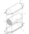
- the exhaust gas treatment device has a columnar exhaust gas treatment body 2, a metal casing 3 that houses the exhaust gas treatment body 2, and an exhaust gas treatment body 2. It is composed of a holding material 1 which is rotated and is filled in a gap between the exhaust gas treating body 2 and the casing 3.
- the exhaust gas treatment body 2 for example, a cylindrical honeycomb shaped body made of cordierite or the like on which a precious metal catalyst or the like is carried is generally used, and therefore, in the gap between the exhaust gas treatment body 2 and the casing 3.
- the holding material 1 to be filled has high temperature heat resistance, and safely holds the exhaust gas treating body 2 so that the exhaust gas treating body 2 does not collide with the casing 3 and is not damaged by vibration or the like while the vehicle is running. It is necessary to have both the function to perform and the function to seal the unpurified exhaust gas so as not to leak from the gap between the exhaust gas processing body 2 and the casing 3 (see, for example, Patent Document 1).
- ceramic fibers such as alumina fibers have been proposed individually or mixed and assembled in a mat shape with a predetermined thickness.
- Patent Document 1 has a problem that the surface pressure locally varies greatly when it is wound around the exhaust gas treating body and filled in the casing.
- an object of the present invention is to hold an exhaust gas treatment device which is wound around an exhaust gas treatment body, is assembled together with the exhaust gas treatment body in a casing, and is less likely to cause local variations in surface pressure when pressed. Is to provide wood.
- the present inventors did not close the groove formed on the surface of the holding material on the exhaust gas treatment body side when wound around the exhaust gas treatment body.
- the present invention has been completed by finding that a groove that is closed by being assembled in the casing together with the exhaust gas treating body makes it difficult for local surface pressure to vary.
- the present invention (1) is wound around a columnar exhaust gas treating body and assembled in a casing together with the exhaust gas treating body to fill a gap between the exhaust gas treating body and the casing, And a holding material for an exhaust gas treatment device for holding the exhaust gas treatment body, Including inorganic fiber and organic binder, A first surface on which a groove extending in the width direction is formed, and a second surface located on the opposite side of the first surface, The groove is not closed when wound around the exhaust gas processing body, and is closed by being assembled with the exhaust gas processing body in the casing, A holding material for an exhaust gas treatment device, characterized by:
- the present invention (2) is wound around a columnar exhaust gas treating body and filled in the casing together with the exhaust gas treating body, filling a gap between the exhaust gas treating body and the casing, and And a holding material for an exhaust gas treatment device for holding the exhaust gas treatment body, Including inorganic fiber and organic binder, A first surface on which a groove extending in the width direction is formed, and a second surface located on the opposite side of the first surface,
- the groove is V-shaped in a cross-sectional view taken in the winding direction, has a groove width a of 2 to 30 mm, a groove depth b of 1.0 to 9.0 mm, and an inter-groove length d.
- the present invention provides a holding material for an exhaust gas treatment device, which is characterized by:
- the invention (3) is characterized in that the ratio (b/e) of the groove depth b to the thickness e of the holding material for the exhaust gas treatment device is 0.10 to 0.80.
- a holding material for an exhaust gas treatment device is provided.
- the shape of the groove is a shape in which a linear first inclined portion and a linear second inclined portion are connected at the deepest portion in a cross-sectional view taken in the winding direction.
- the present invention provides a holding material for an exhaust gas treatment device according to (2) or (3).
- the groove has a shape in which a linear first inclined portion and a linear second inclined portion are connected via a downwardly convex arcuate bottom portion.
- the present invention provides the holding material for an exhaust gas treatment device according to any one of (2) to (4).
- the shape of the groove is such that, in a cross-sectional view taken along the winding direction, the arc-shaped first inclined portion is convex inside the groove and the arc-shaped second inclined portion is convex inside the groove.
- the present invention provides the holding material for an exhaust gas treatment device according to any one of (2) to (5), which has a shape in which it is connected at the deepest part.
- the present invention (7) is characterized in that the holding material for an exhaust gas treatment device is a heat and pressure molded product of a wet molded product containing the inorganic fiber and the organic binder. 6) To provide a holding material for any exhaust gas treatment device.
- the present invention (8) is a molded product which is compressed to a thickness of 1/10 to 4/5 with respect to the thickness of the wet molded product, according to any one of (1) to (7) A holding material for an exhaust gas treatment device is provided.
- the present invention (9) has a columnar exhaust gas treatment body and a casing for housing the exhaust gas treatment body, and a gap between the exhaust gas treatment body and the casing is (1) after heating. )
- An exhaust gas treatment device is provided which is filled with a holding material for an exhaust gas treatment device.
- a holding material for an exhaust gas treatment device which is wound around an exhaust gas treatment body, is assembled together with the exhaust gas treatment body in a casing, and is less likely to cause local variations in surface pressure when pressed. Can be provided.
- FIG. 3 is a schematic perspective view showing an exhaust gas treatment device using the exhaust gas treatment device holding material of the present invention.
- FIG. 3 is a schematic cross-sectional view of an exhaust gas treatment device using the exhaust gas treatment device holding material of the present invention. It is a typical perspective view showing a holding material for exhaust gas processing equipment of the present invention. It is a top view of the holding material for exhaust gas treatment apparatuses shown in FIG. It is the figure which looked at the holding material for exhaust gas treatment equipments shown in FIG. 3 from the direction of the code
- FIG. 3 is a schematic perspective view showing an exhaust gas treatment device using the exhaust gas treatment device holding material of the present invention.
- FIG. 3 is a schematic cross-sectional view of an exhaust gas treatment device using the exhaust gas treatment device holding material of the present invention. It is a typical perspective view showing a holding material for exhaust gas processing
- FIG. 7 is a diagram showing a state in which the casing is filled with the exhaust gas treating body shown in FIG. 6 and the exhaust gas treating device holding material wound around the exhaust gas treating body. It is a typical sectional view showing a holding material for exhaust gas treatment equipment of a first form of the present invention. It is a typical sectional view showing the holding material for exhaust gas treatment equipment of the second form of the present invention. It is a typical sectional view showing the holding material for exhaust gas treatment equipment of the third form of the present invention. It is a schematic diagram which shows a mode that the holding material for exhaust gas treatment apparatuses of this invention is manufactured.
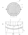
- FIG. 1 is a schematic view showing an exhaust gas treatment device in which the holding material for an exhaust gas treatment device of the present invention is used, and is a perspective view showing the arrangement of the exhaust gas treatment device.
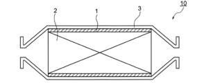
- FIG. 2 is a schematic cross-sectional view of an exhaust gas treatment device in which the holding material for an exhaust gas treatment device of the present invention is used.
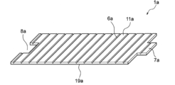
- FIG. 3 is a schematic perspective view showing a holding material for an exhaust gas treatment device of the present invention.
- FIG. 4 is a plan view of the holding material for the exhaust gas treatment device shown in FIG.
- FIG. 5 is a diagram of the holding material for the exhaust gas treatment device shown in FIG. 3, viewed from the direction of reference numeral 27 in FIG. 4.
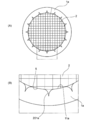
- FIG. 6 is a diagram showing a state in which the holding material for the exhaust gas treatment device shown in FIG. 3 is wound around the exhaust gas treatment body
- FIG. 6(A) is a diagram seen from the inlet side of the exhaust gas
- (B) is an enlarged view of a portion surrounded by a dotted line in (A).
- FIG. 7 is a diagram showing a state in which the exhaust gas processing body and the exhaust gas processing device holding member wound around the exhaust gas processing body shown in FIG. 6 are assembled and pressed into the casing.
- the exhaust gas treatment device 10 includes a columnar exhaust gas treatment body 2, a metal casing 3 for housing the exhaust gas treatment body 2, and an exhaust gas treatment body 2.
- the exhaust gas processing body 2 and the casing 3 are filled with the exhaust gas processing device holding material 1.
- the shape of the exhaust gas treatment device holding material 1a shown in FIGS. 3 to 5 is the first surface 11a in which the groove 6a extending in the width direction 26 is formed, and the second surface located on the opposite side of the first surface 11a. 19a, and has a flat plate shape.
- the exhaust gas treatment device holding material 1a has an engaging convex portion 7a on one end side in the winding direction 28 and an engaging concave portion 8a on the other end side in the winding direction 28 in plan view.
- the engaging convex shape portion 7a and the engaging concave shape portion 8a form one end and the other end of the exhaust gas processing device holding material 1a when the exhaust gas processing device holding material 1a is wound around the exhaust gas processing body. Are engaged to tie together.
- the first surface 11a is a surface that comes into contact with the outer surface of the exhaust gas processing body when the exhaust gas processing device holding material 1a is wound around the exhaust gas processing body.
- a V-shaped groove 6a extending in the width direction 26 is formed on the first surface 11a.
- the exhaust gas treatment device holding material 1a bends from the V-shaped groove as a starting point.
- the first surface 11a of the exhaust gas treatment device holding material 1a contacts the outer side surface 5 of the exhaust gas treatment body 2. Since the V-shaped groove is formed in the exhaust gas processing device holding material 1a, the exhaust gas processing device holding material 1a is easily bent from the V-shaped groove as a starting point, and is used for the exhaust gas processing device.
- the holding material 1a is prevented from being bent irregularly. Therefore, the holding material 1a for the exhaust gas treatment device can be sufficiently curved to follow the curved surface of the outer side surface 5 of the exhaust gas treatment body 2 when wound around the exhaust gas treatment body 2.
- the exhaust gas treatment device holding material 1a does not completely close the V-shaped groove 6a only by being wound around the exhaust gas treatment body 2. That is, the V-shaped groove 6a of the exhaust gas treatment device holding material 1a before being wound around the exhaust gas treatment body 2 is wound around the exhaust gas treatment body 2 and before being filled in the casing. Is a V-shaped groove 201a that is partially closed near the V-shaped bottom but is not completely closed.
- the holding material for the exhaust gas treatment device of the present invention may be one in which the groove of the holding material for the exhaust gas treatment device is not completely closed when wound around the exhaust gas treatment body.
- the exhaust gas processing body 2 and the exhaust gas processing device holding member 1a wound around the exhaust gas processing body 2 are assembled together with the exhaust gas processing body 2 in the casing and press-fitted.
- the exhaust gas treatment device holding material 1a is compressed, and the exhaust gas treatment device holding material 1a is compressed to exist in the exhaust gas treatment device holding material 1a before being filled in the casing.
- the V-shaped groove 201a that has been used is completely closed to form a closed portion 202a. Then, the gap between the exhaust gas processing body 2 and the exhaust gas processing device holding material 1a disappears.
- the holding material for an exhaust gas treatment device is wound around a columnar exhaust gas treatment body and assembled in a casing together with the exhaust gas treatment body, and the exhaust gas treatment body and the casing.
- the holding material for an exhaust gas treatment device is wound around a columnar exhaust gas treatment body and assembled in a casing together with the exhaust gas treatment body,
- the groove is V-shaped in a cross-sectional view taken in the winding direction, has a width a of 2 to 30 mm, a groove depth b of 1.0 to 9.0 mm, and a groove length d.
- the ratio (a/d) of the groove width a is 0.05 to 2.5, Is a holding material for an exhaust gas treatment device.
- the common point between the holding material for exhaust gas treatment device of the first aspect of the present invention and the holding material for exhaust gas treatment device of the second aspect of the present invention is the holding material for exhaust gas treatment device of the present invention.
- the material will be generically described.
- the holding material for an exhaust gas treatment device of the present invention contains an inorganic fiber and an organic binder.
- the holding material for an exhaust gas treatment device of the present invention is a mat made of inorganic fibers, which is a compression molded body of an inorganic fiber mat, and the shape state at the time of compression molding is retained by an organic binder.
- Examples of the inorganic fiber related to the holding material for the exhaust gas treatment device of the present invention include one or more selected from alumina fiber, mullite fiber, alumina silicate fiber, silica fiber and biosoluble fiber.
- Alumina fibers are amorphous fibers or polycrystalline fibers whose main component is alumina (Al 2 O 3 ), and those containing 90 to 99% by mass of Al 2 O 3 and 1 to 10% by mass of SiO 2. More preferably, those containing 95 to 99 mass% of Al 2 O 3 and 1 to 5 mass% of SiO 2 are more preferable, and those containing 96 to 99 mass% of Al 2 O 3 and 1 to 4 mass% of SiO 2 are further preferable.
- Mullite fibers are amorphous fibers or polycrystalline fibers whose main components are alumina (Al 2 O 3 ) and silica (SiO 2 ), and 60 to 90% by mass of Al 2 O 3 and 10% by weight of SiO 2 .
- the content of Al 2 O 3 is 70 to 85 mass %
- the content of SiO 2 is 15 to 30 mass %
- the content of Al 2 O 3 is 72 to 80 mass %
- the content of SiO 2 is 20 to 20 mass %.
- Those containing 28% by mass are more preferable.
- Alumina silicate fibers are amorphous fibers or polycrystalline fibers containing alumina (Al 2 O 3 ) and silica (SiO 2 ) as main components, and contain 30 to 60% by mass of Al 2 O 3 and 40% by weight of SiO 2 . To 70% by mass, preferably 35 to 60% by mass of Al 2 O 3 and 40 to 65% by mass of SiO 2 , more preferably 40 to 60% by mass of Al 2 O 3 and 40 to 40% of SiO 2. Those containing 60 mass% are more preferable.
- the silica fiber is an amorphous fiber or a polycrystalline fiber containing silica (SiO 2 ) as a main component, and preferably contains 1 to 20% by mass of Al 2 O 3 and 80 to 99% by mass of SiO 2 .
- a material containing 1 to 10 mass% of Al 2 O 3 and 90 to 99 mass% of SiO 2 is more preferable, and a material containing 1 to 5 mass% of Al 2 O 3 and 95 to 99 mass% of SiO 2 is further preferable.
- the biosoluble fiber is not particularly limited as long as it is an inorganic fiber having a solubility (degradability) that is decomposed in a living body, and examples thereof include artificial amorphous inorganic fibers to which solubility in a living body is imparted.
- the average length of the inorganic fibers is preferably 0.01 to 100 mm, more preferably 0.05 to 50 mm, further preferably 0.1 to 10 mm.
- the average length of the inorganic fibers is an arithmetic average value when the length of 100 inorganic fibers is measured with an optical microscope.
- organic binder relating to the holding material for the exhaust gas treatment device of the present invention, one or more selected from starch, polymer flocculant, pulp and suitable emulsion can be mentioned.
- the exhaust gas treatment device holding material of the present invention may contain an inorganic binder, a polymer aggregating material, and the like, if necessary, in addition to the inorganic fiber and the organic binder.
- a slurry containing inorganic fibers and an organic binder is prepared, and then the slurry is wet-molded to obtain a wet-molded body, and then the wet-molded body is heated and heated.
- examples include a molded product obtained by pressurizing and molding, that is, a hot-pressed molded product of a wet molded product containing inorganic fibers and an organic binder.
- the holding material for an exhaust gas treatment device of the present invention is a molded product which is preferably compressed to a thickness of 1/10 to 4/5, particularly preferably 1/5 to 7/10, of the thickness of the wet molded product. .. That is, the holding material for an exhaust gas treatment device of the present invention is heated and compressed to a thickness of preferably 1/10 to 4/5, particularly preferably 1/5 to 7/10 by heating and compressing a wet molded body. It was created by
- the exhaust gas treatment device holding material of the present invention has a flat plate shape including a first surface and a second surface opposite to the first surface.
- the first surface is a surface that comes into contact with the outer surface of the exhaust gas treating body when wound around the exhaust gas treating body, that is, a surface that is the inner side
- the second surface is a surface that is the outer side. is there.
- the length, width, and thickness in the winding direction of the holding material for an exhaust gas treatment device of the present invention are appropriately selected.
- the exhaust gas treatment device holding material of the present invention usually has an engaging convex portion on one end side in the winding direction and an engaging concave portion on the other end side in the winding direction in plan view.
- the engaging convex shape portion and the engaging concave shape portion are for engaging in the exhaust gas treatment device of the present invention by engaging when the holding material for exhaust gas treatment device of the present invention is wound around the exhaust gas treatment body. It is a part for connecting one end side and the other end side of the holding material.
- the shapes of the engaging convex shape portion and the engaging concave shape portion are appropriately selected.
- a groove extending in the width direction is formed on the first surface of the holding material for an exhaust gas treatment device according to the first aspect of the present invention.
- the groove formed on the first surface of the holding material for an exhaust gas treatment device of the first aspect of the present invention does not close when wound around the exhaust gas treatment body, and inside the casing together with the exhaust gas treatment body. It is a groove having a shape that closes when it is assembled to.
- the shape of the groove formed on the first surface of the holding material for an exhaust gas treatment device according to the first aspect of the present invention does not close when wound around the exhaust gas treatment body, and together with the exhaust gas treatment body
- the shape is not particularly limited as long as it is assembled in the casing and closed by being press-fitted.
- the groove formed on the first surface of the exhaust gas treatment device holding member according to the first aspect of the present invention does not close when wound around the exhaust gas treatment body, and together with the exhaust gas treatment body. Since the exhaust gas treatment device holding member according to the first aspect of the present invention is assembled in the casing together with the exhaust gas treatment body and is closed by being press-fitted, it is locally attached. It is difficult for the surface pressure to vary.
- a V-shaped groove extending in the width direction is formed on the first surface of the holding material for exhaust gas treatment device of the second embodiment of the present invention.
- the groove formed on the first surface has a V-shaped surface on which the groove is formed in a sectional view taken in the winding direction.
- the exhaust gas treatment device holding material according to the second aspect of the present invention includes a flat first inclined portion and a flat second inclined portion, and the first inclined portion and the second inclined portion are the deepest portions.
- An exhaust gas treatment device holding material (hereinafter also referred to as an exhaust gas treatment device holding material of the second (A) mode of the present invention) in which connected grooves are formed can be mentioned.
- the V-shaped groove formed in the exhaust gas treatment device holding material of the second (A) mode of the present invention has a linear first inclined portion in a cross-sectional view taken in the winding direction.
- the linear second slanted portion is connected to the deepest portion.
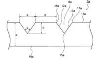
- FIG. 8 shows an example of the form of the holding material for an exhaust gas treatment device according to the second (A) form of the present invention.
- FIG. 8 is an enlarged view of a cross section of the holding material 1a for exhaust gas treatment device taken in the winding direction.
- the V-shaped groove 6a of the second (A) form is composed of a flat first inclined portion 12a and a flat second inclined portion 13a.
- the first inclined portion 12a and the second inclined portion 13a are the deepest portion 15a and are directly connected.
- the width a of the V-shaped groove 6a in the second (A) form means the intersection of the first inclined portion 12a of the one V-shaped groove 6a and the first surface 11a in a cross-sectional view. 16a and the intersection 17a of the second inclined portion 13a of the same V-shaped groove 6a and the first surface 11a.
- the groove depth b of the V-shaped groove 6a of the first embodiment refers to the depth of the V-shaped groove 6a.
- the inter-groove length d of the V-shaped groove 6a of the second (A) form means the intersection 16a between the first inclined portion 12a of the one V-shaped groove 6a and the first surface 11a, and the adjacent point 16a.
- the angle c of the inclined portion of the V-shaped groove 6a in the second (A) form refers to the angle formed by the first inclined portion 12a and the second inclined portion 13a in a cross-sectional view.
- the holding material for an exhaust gas treatment device includes a flat first inclined portion and a flat second inclined portion, and the first inclined portion and the second inclined portion are on the lower side.
- a holding material for an exhaust gas treatment device (hereinafter, also referred to as a holding material for an exhaust gas treatment device in the second (B) mode of the present invention) in which a groove is formed which is connected to the bottom of a convex curved surface.
- the V-shaped groove formed in the exhaust gas treatment device holding material of the second (B) aspect of the present invention has a linear first inclined portion in a cross-sectional view taken in the winding direction.
- the linear second inclined portion has a shape in which a downwardly convex arcuate bottom portion is connected.
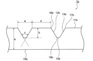
- FIG. 9 shows an example of the form of the holding material for an exhaust gas treatment device according to the second (B) form of the present invention.
- FIG. 9 is an enlarged view of a cross section of the exhaust gas treatment device holding material 1b taken in the winding direction.
- the V-shaped groove 6b of the second (B) form is composed of a flat first inclined portion 12b and a flat second inclined portion 13b.
- the first sloping portion 12b and the second sloping portion 13b have a curved surface that is convex downward, and are connected to each other via an arcuate bottom portion that is convex downward in cross-sectional view.
- the width a of the V-shaped groove 6b of the second (B) form means the intersection of the first inclined portion 12b of the V-shaped groove 6b and the first surface 11b in a cross-sectional view. 16b and the intersection 17b of the second inclined portion 13b of the same V-shaped groove 6b and the first surface 11b.
- the groove depth b of the V-shaped groove 6b in the second (B) form refers to the depth of the V-shaped groove 6b.
- the inter-groove length d of the V-shaped groove 6b in the second (B) form means the intersection 16b between the first inclined portion 12b of the one V-shaped groove 6b and the first surface 11b and the adjacent point 16b.
- the angle c of the inclined portion of the V-shaped groove 6b in the second (B) form refers to the angle formed by the extension line of the first inclined portion 12b and the extension line of the second inclined portion 13b in cross-sectional view.
- the exhaust gas treatment device holding material according to the second aspect of the present invention comprises a curved first curved inclined surface inside the groove and a convex second curved curved surface inside the groove.
- a holding material for an exhaust gas treatment device (hereinafter also referred to as a holding material for an exhaust gas treatment device according to the second (C) mode of the present invention) in which a groove is formed in which one inclined portion and the second inclined portion are connected at the deepest portion. Described).
- the V-shaped groove formed in the exhaust gas treatment device holding material of the second (C) aspect of the present invention has a circular arc shape that is convex inside the groove in a cross-sectional view taken in the winding direction.
- the first inclined portion and the second inclined portion having an arcuate shape convex inside the groove are connected at the deepest portion.
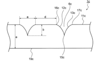
- FIG. 10 shows an example of the form of the holding material for an exhaust gas treatment device according to the second (C) form of the present invention.
- FIG. 10 is an enlarged view of a cross section of the exhaust gas treatment device holding material 1c taken in the winding direction.
- the V-shaped groove 6c of the second (C) form is a curved surface that is convex inside the groove, and is convex inside the groove in cross-sectional view.
- the first slanted portion 12c and the second slanted portion 12c having an arcuate shape and a second curved slanted portion 13c having a curved surface that is convex inside the groove and convex inside the groove in a cross-sectional view.
- the inclined portion 13c is directly connected to the deepest portion 15c.
- the width a of the V-shaped groove 6c in the second (C) form means the intersection of the first inclined portion 12c of the one V-shaped groove 6c and the first surface 11c in a cross-sectional view. 16c and the point 17c of intersection of the second inclined portion 13c of the same V-shaped groove 6c and the first surface 11c.
- the groove depth b of the V-shaped groove 6c in the second (C) form refers to the depth of the V-shaped groove 6c.
- the inter-groove length d of the V-shaped groove 6c in the second (C) form means the intersection 16c between the first inclined portion 12c and the first surface 11c of one V-shaped groove 6c and the adjacent point 16c. It indicates the distance between the second inclined portion 13c of the V-shaped groove 6c and the intersection 17c of the first surface 11c.
- the groove width a of the V-shaped groove is 2 to 30 mm, preferably 5 to 23 mm, particularly preferably 10 to 20 mm.
- the depth b is 1.0 to 9.0 mm, preferably 2.0 to 8.0 mm, particularly preferably 2.5 to 7.5 mm, and the ratio of the groove width a to the groove length d ( a/d) is 0.05 to 2.5, preferably 0.1 to 2.2, particularly preferably 0.2 to 2.0.
- the ratio (a/d) of the groove width a of the V-shaped groove to the groove width a, the groove depth b, and the inter-groove length d is within the above range, so that the exhaust gas according to the second embodiment of the present invention Since the holding material for the treatment device is easily bent from the V-shaped groove as a starting point, the holding material for the exhaust gas treatment device of the second aspect of the present invention is prevented from being bent irregularly, and therefore the book
- the holding material for an exhaust gas treatment device according to the second aspect of the invention can bend sufficiently following the curved surface of the outer surface of the exhaust gas treatment body.
- the V-shaped groove is The holding material for the exhaust gas treatment device of the second form does not close when wound around the exhaust gas treatment body, and also closes when filled in the casing together with the exhaust gas treatment body, so the casing is filled. When applied, it is difficult for local surface pressure to vary.
- the angle c of the inclined portion of the V-shaped groove is Is preferably 30 to 150°, particularly preferably 45 to 130°.
- the ratio (b/e) of the groove depth b of the V-shaped groove to the thickness e of the exhaust gas treatment device holding material is preferably 0. 10 to 0.80, particularly preferably 0.20 to 0.70.
- V-shaped groove of the holding material for an exhaust gas treatment device is deformed so that the first inclined portion and the second inclined portion are aligned when wound around the exhaust gas treating body. And block it.
- the V-shaped groove formed on the first surface of the holding material for exhaust gas treatment device according to the second embodiment of the present invention does not close when wound around the exhaust gas treatment body, and the exhaust gas is exhausted. Since the exhaust gas treatment device holding member according to the second aspect of the present invention is assembled together with the exhaust gas treatment body in the casing and is press-fitted, it is closed by being assembled in the casing together with the gas treatment body and press-fitted. Occasionally, local variations in surface pressure are unlikely to occur. At this time, in the exhaust gas treatment device holding material of the second aspect of the present invention, when wound around the exhaust gas treatment body, uniform wrinkles are formed along the groove portion, so the exhaust gas treatment is performed in the casing. When assembled together with the body and press-fitted, local variations in surface pressure hardly occur.
- the holding material for an exhaust gas treatment device of the present invention is wound around a columnar exhaust gas treatment body and arranged in a casing together with the exhaust gas treatment body. After that, the holding material for an exhaust gas treatment device of the present invention is heated in the casing together with the exhaust gas treatment body, so that the organic binder is thermally decomposed and disappears. As a result, the compressed state of the mat made of the inorganic fiber which has been in the compressed state is released, and the restoring force for returning to the state before the compression causes the gap between the exhaust gas treating body and the casing to generate the exhaust gas of the present invention.
- the exhaust gas treatment body is inside the casing. It is held at a position so as not to collide with the casing due to vibration or the like and is not damaged, and is sealed so that unpurified exhaust gas does not leak from the gap between the exhaust gas treating body and the casing.
- the exhaust gas treating body around which the holding material for an exhaust gas treating device of the present invention is wound is not particularly limited, and examples thereof include those in which a precious metal catalyst is carried on a catalyst carrier.
- the catalyst carrier may be made of metal, alloy, ceramic or the like.
- Examples of the structure of the catalyst carrier include a honeycomb shaped body, a filter structure such as a gasoline particulate filter (GPF), and a diesel particulate filter (DPF).
- the shape of the exhaust gas treatment body is usually cylindrical.
- the diameter of the exhaust gas treating body is appropriately selected.
- the method for manufacturing the holding material for an exhaust gas treatment device of the present invention is not particularly limited.
- an inorganic fiber, an organic binder, and, if necessary, an inorganic binder, a polymer aggregating material, and the like are dispersed in a dispersion medium such as water or a polar organic solvent and mixed.
- a dispersion medium such as water or a polar organic solvent and mixed.
- the wet molded body 21 is molded by heating and pressurizing the wet molded body 21 with the upper heating press member 23a and the lower heating press member 24a (B).
- Material 1a is obtained (C).
- the solvent used when forming the slurry is not particularly limited, but examples thereof include water and polar organic solvents.
- water include distilled water, ion-exchanged water, tap water, ground water, industrial water, and the like
- polar organic solvents include ethanol, monohydric alcohols such as propanol, and divalent alcohols such as ethylene glycol. The kind is mentioned.
- the concentration of the total solid content contained in the slurry is preferably 0.05 to 5% by mass, more preferably 0.1 to 2% by mass, and further preferably 0.2 to 1% by mass.
- the exhaust gas treatment apparatus of the present invention includes a columnar exhaust gas treatment body and a casing that houses the exhaust gas treatment body, and the gap between the exhaust gas treatment body and the casing is the exhaust gas of the present invention after heating.
- the exhaust gas treatment device is characterized in that it is filled with a treatment device holding material.
- Example 1 100 parts by mass of inorganic fibers (alumina fibers) and 10 parts by mass of an organic binder (acrylic resin) were dispersed in water and mixed to prepare a slurry. Next, the obtained slurry was wet-molded to obtain a 450 mm ⁇ 300 mm ⁇ 30 mm wet-molded body. Next, the obtained wet-molded body is heated and pressure-molded by an upper heating press having a V-shaped groove forming convex portion on the lower surface and a lower heating press having a flat upper surface to form a V-shape shown in FIG. An exhaust gas treatment device holding material A having a groove formed therein was obtained. At this time, the holding material for the exhaust gas treatment device was compressed to a thickness of 12 mm.
- inorganic fibers alumina fibers
- an organic binder acrylic resin
- the holding material A for an exhaust gas treatment device obtained above was wound around an exhaust gas treatment body (outer diameter 110 mm, length 100 mm). At this time, the V-shaped groove was not closed. There were uniform wrinkles along the groove.
- the exhaust gas treating body around which the exhaust gas treatment device holding material A was wound was assembled into a cylinder having an inner diameter of 118 mm as a simulated casing. At this time, the V-shaped groove was closed.
- Example 2 The same procedure as in Example 1 was performed, except that the shape of the holding material for the exhaust gas treatment device was changed as shown below. As a result, when the holding material for the exhaust gas treatment device was wound around the exhaust gas treatment body, the V-shaped groove was not blocked. There were uniform wrinkles along the groove. Further, when the exhaust gas treating body around which the holding material for the exhaust gas treatment device was wound was assembled as a simulated casing into a cylinder having an inner diameter of 118 mm, the V-shaped groove was closed.
- ⁇ Shape of holding material for exhaust gas treatment device Groove width a: 15 mm, groove depth b: 7.5 mm, angle c of a V-shaped groove c: 90°, groove length d: 25 mm, ratio of groove width a to groove length d ( a/d): 0.6, ratio (b/e) of groove depth b to thickness e of holding material for exhaust gas treatment device: 0.63
- Example 1 The same procedure as in Example 1 was performed, except that the V-shaped groove was not formed in the holding material for the exhaust gas treatment device. As a result, when the holding material for the exhaust gas treatment device was wound around the exhaust gas treatment body, wrinkles that were uneven in both the generation site and the size were generated.
Landscapes
- Chemical & Material Sciences (AREA)
- Engineering & Computer Science (AREA)
- Chemical Kinetics & Catalysis (AREA)
- Combustion & Propulsion (AREA)
- Health & Medical Sciences (AREA)
- Mechanical Engineering (AREA)
- Toxicology (AREA)
- General Engineering & Computer Science (AREA)
- Biomedical Technology (AREA)
- Environmental & Geological Engineering (AREA)
- Analytical Chemistry (AREA)
- General Chemical & Material Sciences (AREA)
- Oil, Petroleum & Natural Gas (AREA)
- Exhaust Gas After Treatment (AREA)
Priority Applications (1)
| Application Number | Priority Date | Filing Date | Title |
|---|---|---|---|
| JP2020563189A JPWO2020137862A1 (ja) | 2018-12-28 | 2019-12-20 | 排気ガス処理装置用保持材及び排気ガス処理装置 |
Applications Claiming Priority (2)
| Application Number | Priority Date | Filing Date | Title |
|---|---|---|---|
| JP2018246904 | 2018-12-28 | ||
| JP2018-246904 | 2018-12-28 |
Publications (1)
| Publication Number | Publication Date |
|---|---|
| WO2020137862A1 true WO2020137862A1 (ja) | 2020-07-02 |
Family
ID=71127751
Family Applications (1)
| Application Number | Title | Priority Date | Filing Date |
|---|---|---|---|
| PCT/JP2019/050050 Ceased WO2020137862A1 (ja) | 2018-12-28 | 2019-12-20 | 排気ガス処理装置用保持材及び排気ガス処理装置 |
Country Status (2)
| Country | Link |
|---|---|
| JP (1) | JPWO2020137862A1 (enExample) |
| WO (1) | WO2020137862A1 (enExample) |
Citations (4)
| Publication number | Priority date | Publication date | Assignee | Title |
|---|---|---|---|---|
| JPH10337480A (ja) * | 1997-04-10 | 1998-12-22 | Mitsubishi Chem Corp | 触媒コンバーター |
| JP2008045521A (ja) * | 2006-08-21 | 2008-02-28 | Ibiden Co Ltd | 保持シール材および排気ガス処理装置 |
| JP2013245554A (ja) * | 2012-05-23 | 2013-12-09 | Three M Innovative Properties Co | 取付システム及び汚染制御装置 |
| JP2017031869A (ja) * | 2015-07-31 | 2017-02-09 | イビデン株式会社 | 保持シール材、巻付体、排ガス浄化装置、保持シール材の製造方法、巻付体の製造方法及び排ガス浄化装置の製造方法 |
-
2019
- 2019-12-20 JP JP2020563189A patent/JPWO2020137862A1/ja active Pending
- 2019-12-20 WO PCT/JP2019/050050 patent/WO2020137862A1/ja not_active Ceased
Patent Citations (4)
| Publication number | Priority date | Publication date | Assignee | Title |
|---|---|---|---|---|
| JPH10337480A (ja) * | 1997-04-10 | 1998-12-22 | Mitsubishi Chem Corp | 触媒コンバーター |
| JP2008045521A (ja) * | 2006-08-21 | 2008-02-28 | Ibiden Co Ltd | 保持シール材および排気ガス処理装置 |
| JP2013245554A (ja) * | 2012-05-23 | 2013-12-09 | Three M Innovative Properties Co | 取付システム及び汚染制御装置 |
| JP2017031869A (ja) * | 2015-07-31 | 2017-02-09 | イビデン株式会社 | 保持シール材、巻付体、排ガス浄化装置、保持シール材の製造方法、巻付体の製造方法及び排ガス浄化装置の製造方法 |
Also Published As
| Publication number | Publication date |
|---|---|
| JPWO2020137862A1 (ja) | 2021-11-18 |
Similar Documents
| Publication | Publication Date | Title |
|---|---|---|
| EP1867847B1 (en) | Holding sealer, exhaust gas processing device and manufacturing method of the same | |
| JP6030721B2 (ja) | マット及びその製造方法 | |
| WO2002033233A1 (en) | Holding seal material for catalytic converter and method of manufacturing the holding seal material | |
| CN100386507C (zh) | 催化剂转化器和柴油颗粒过滤系统 | |
| CN1352726A (zh) | 用于污染控制装置的高温衬垫 | |
| KR100707150B1 (ko) | 섬유 매트 | |
| KR20120094905A (ko) | 오염 제어 장치용 저전단 장착 매트 | |
| JP6012968B2 (ja) | 気体処理装置用保持材、気体処理装置及びこれらの製造方法 | |
| JP4918433B2 (ja) | 触媒コンバーター、触媒コンバーター用保持材及びその製造方法 | |
| US9759112B2 (en) | Retainer for gas processing device, gas processing device, and manufacturing methods therefor | |
| JP2006223920A (ja) | 汚染コントロール要素の保持材及び汚染コントロール装置 | |
| JP5912931B2 (ja) | 気体処理装置用保持材、気体処理装置及びこれらの製造方法 | |
| WO2020137862A1 (ja) | 排気ガス処理装置用保持材及び排気ガス処理装置 | |
| JP3717111B2 (ja) | セラミックハニカムフィルタ | |
| JP6486328B2 (ja) | 排気ガス処理装置用保持材および排気ガス処理装置 | |
| JP4382414B2 (ja) | 保持シール材、及び、排気ガス浄化装置 | |
| JP4465792B2 (ja) | 排ガス浄化用触媒コンバーター及びディーゼルパティキュレートフィルターシステム,並びにこれらの製造方法 | |
| JP4688599B2 (ja) | 保持シール材および排気ガス浄化装置 | |
| JP2014034968A (ja) | 排ガス浄化装置の製造方法及び排ガス浄化装置 | |
| KR20120125981A (ko) | 절연 배기 가스 장치를 생산하는 방법 | |
| US20150082759A1 (en) | Holding sealing material, method for producing holding sealing material, method for manufacturing exhaust gas purifying apparatus, and exhaust gas purifying apparatus | |
| JP6063799B2 (ja) | 気体処理装置用保持材、気体処理装置及びその製造方法 | |
| JP7313173B2 (ja) | マット材及び排ガス浄化装置 | |
| JP6017833B2 (ja) | 気体処理装置及び気体処理方法 | |
| JP7313174B2 (ja) | マット材、排ガス浄化装置及び排気管 |
Legal Events
| Date | Code | Title | Description |
|---|---|---|---|
| 121 | Ep: the epo has been informed by wipo that ep was designated in this application |
Ref document number: 19904538 Country of ref document: EP Kind code of ref document: A1 |
|
| ENP | Entry into the national phase |
Ref document number: 2020563189 Country of ref document: JP Kind code of ref document: A |
|
| NENP | Non-entry into the national phase |
Ref country code: DE |
|
| 122 | Ep: pct application non-entry in european phase |
Ref document number: 19904538 Country of ref document: EP Kind code of ref document: A1 |