WO2020137844A1 - 金型管理装置及び金型管理方法 - Google Patents
金型管理装置及び金型管理方法 Download PDFInfo
- Publication number
- WO2020137844A1 WO2020137844A1 PCT/JP2019/049984 JP2019049984W WO2020137844A1 WO 2020137844 A1 WO2020137844 A1 WO 2020137844A1 JP 2019049984 W JP2019049984 W JP 2019049984W WO 2020137844 A1 WO2020137844 A1 WO 2020137844A1
- Authority
- WO
- WIPO (PCT)
- Prior art keywords
- die
- mold
- punch
- management information
- amount
- Prior art date
- Legal status (The legal status is an assumption and is not a legal conclusion. Google has not performed a legal analysis and makes no representation as to the accuracy of the status listed.)
- Ceased
Links
Images





Classifications
-
- B—PERFORMING OPERATIONS; TRANSPORTING
- B21—MECHANICAL METAL-WORKING WITHOUT ESSENTIALLY REMOVING MATERIAL; PUNCHING METAL
- B21D—WORKING OR PROCESSING OF SHEET METAL OR METAL TUBES, RODS OR PROFILES WITHOUT ESSENTIALLY REMOVING MATERIAL; PUNCHING METAL
- B21D28/00—Shaping by press-cutting; Perforating
-
- B—PERFORMING OPERATIONS; TRANSPORTING
- B21—MECHANICAL METAL-WORKING WITHOUT ESSENTIALLY REMOVING MATERIAL; PUNCHING METAL
- B21D—WORKING OR PROCESSING OF SHEET METAL OR METAL TUBES, RODS OR PROFILES WITHOUT ESSENTIALLY REMOVING MATERIAL; PUNCHING METAL
- B21D28/00—Shaping by press-cutting; Perforating
- B21D28/24—Perforating, i.e. punching holes
- B21D28/34—Perforating tools; Die holders
-
- B—PERFORMING OPERATIONS; TRANSPORTING
- B21—MECHANICAL METAL-WORKING WITHOUT ESSENTIALLY REMOVING MATERIAL; PUNCHING METAL
- B21D—WORKING OR PROCESSING OF SHEET METAL OR METAL TUBES, RODS OR PROFILES WITHOUT ESSENTIALLY REMOVING MATERIAL; PUNCHING METAL
- B21D37/00—Tools as parts of machines covered by this subclass
Definitions
- the present disclosure relates to a mold management device and a mold management method.
- the punching machine processes a sheet metal by punching or forming the sheet metal using a set of punch and die.
- the cutting edge of the die wears every time the sheet metal is processed.
- burrs are generated on a processed surface of a product to be manufactured by the sheet metal processing, which deteriorates the quality of the product. Therefore, when the cutting edge is worn beyond the standard, the operator needs to polish the cutting edge with a die grinder.
- An object of one or more embodiments is to provide a mold management apparatus and a mold management method that can reduce the work for managing the state of the blade edge by an operator.
- a punching machine calculates the amount of wear of the punch and the edge of the die when the sheet metal is processed once with a set of punch and die. Then, by accumulating the amount of wear of each time when the set of dies process the sheet metal a plurality of times, a cumulative wear amount calculation unit that calculates the cumulative amount of wear of the punch and the edge of the die, and die management
- the information storage unit stores mold management information in which the die identification code given to each punch and each die and the cumulative wear amount calculated by the cumulative wear amount calculation unit are stored, and each punch is stored.
- a die management information management unit that manages the state of the cutting edge of each die, and the die management information management unit is configured such that any punch or die cutting edge managed by the die management information management unit is a die.
- a mold management device which clears the accumulated wear amount stored corresponding to the mold identification code of a polished punch or die after receiving the polishing record information indicating that polishing has been performed by a grinding machine. ..
- the computer equipment is configured to detect the punch and the cutting edge of the die when the punching machine processes the sheet metal once with the set of the punch and the die.
- the wear amount is calculated, and the cumulative wear amount of the punch and the cutting edge of the die is calculated by accumulating the wear amount of each time when the die set processes the sheet metal a plurality of times, and the die management information storage
- the mold management information in which the mold identification code given to each punch and each die and the calculated accumulated wear amount are associated with each other is stored in the section, and the mold management code is stored in the mold management information storage unit. After receiving the polishing result information indicating that one of the stored punch or die cutting edges has been polished by the die grinder, it is stored in correspondence with the die identification code of the polished punch or die.
- a mold management method for clearing the accumulated wear amount is provided.
- the mold management device and the mold management method of one or more embodiments it is possible to reduce the work for managing the state of the cutting edge by the worker.
- FIG. 1 is a diagram showing a mold management apparatus according to one or more embodiments.
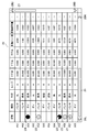
- FIG. 2 is a diagram showing an example of a mold list displayed on the display unit by the mold management apparatus according to one or more embodiments.
- FIG. 3A is a plan view conceptually showing a cutting edge of a circular mold.
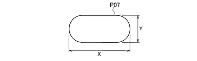
- FIG. 3B is a plan view conceptually showing a cutting edge of an oblong mold.
- FIG. 3C is a plan view conceptually showing a cutting edge of a rectangular die.
- FIG. 3D is a plan view conceptually showing a cutting edge of a long-angled die.
- FIG. 4 is a plan view showing the clearance between the punch and the die.
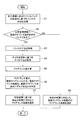
- FIG. 5 is a flowchart showing a partial process when the mold management apparatus and the mold management method of one or more embodiments calculate a cumulative wear amount.
- FIG. 6 is a table showing coefficients according to clearance values used by the mold management device of one or more embodiments to calculate the cumulative wear amount.
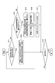
- FIG. 7 is a flowchart showing a process in which the mold management apparatus and the mold management method according to one or more embodiments update the mold management state according to the polishing results of the mold.
- the punching machine 1 is connected to a die management device 2 via a network, and the die management device 2 is connected to a die grinding machine 3 via a network.
- the punching machine 1, the die management device 2, and the die grinder 3 are respectively provided with communication units 11, 201, and 31 for communicating via a network.
- the punching machine 1 is, for example, a turret punch press.
- the mold grinder is sometimes called a mold grinder.
- the punching machine 1 includes, in addition to the communication unit 11, an NC device 12 that controls processing of sheet metal by the punching machine 1.
- the punching machine 1 processes a sheet metal by mounting a die managed by the die management device 2.
- the mold management device 2 can be configured by a server using a computer device connectable to a network.
- the mold management apparatus 2 includes a processing record information storage unit 202, a polishing record information storage unit 203, a hit number accumulation unit 204, a cumulative wear amount calculation unit 205, and a total polishing amount calculation unit 206.
- the mold management device 2 also includes a mold information input unit 207, a mold management information management unit 208, a mold management information storage unit 209, a display control unit 210, a display unit 211, and an operation unit 212.
- At least the hit count accumulating unit 204, the cumulative wear amount calculating unit 205, the total polishing amount calculating unit 206, the mold management information managing unit 208, and the display control unit 210 are configured by a central processing unit (CPU) included in the computer device.
- CPU central processing unit
- the processing record information storage unit 202, the polishing record information storage unit 203, and the mold management information storage unit 209 can be configured by a storage medium included in a computer device.
- the processing record information storage unit 202, the polishing record information storage unit 203, and the mold management information storage unit 209 may be separate storage media or separate storage areas in one storage medium.
- the mold information of the mold managed by the mold management device 2 is input by the mold information input unit 207 and supplied to the mold management information management unit 208.
- the mold information is a mold identification code (hereinafter, mold ID) for uniquely identifying the mold, the type of the mold whether it is a punch or a die, the shape of the mold, and the size of the mold. Information, including the maximum polishing amount that can be polished.
- the mold ID is represented by a plurality of digits or alphabets.
- the information regarding the size of the mold includes a range indicating the type of the size of the mold, the dimension of the cutting edge of the mold, and the length (height) of the mold.
- the mold length is the original length of the mold at the time of shipping.
- the mold information input unit 207 is a reading unit that reads a text file containing mold information.
- the mold information input unit 207 may be a reader that reads mold information represented by a two-dimensional code.
- the mold information may be manually input by the operation unit 212 and supplied to the mold management information management unit 208.
- the mold management information management unit 208 When the mold information is input by the mold information input unit 207 or the operation unit 212, the mold management information management unit 208 writes the mold information for managing each mold into the mold management information storage unit 209. ..
- the mold management information storage unit 209 stores mold information of all molds managed by the mold management device 2.
- a mold ID is given to each mold by, for example, a two-dimensional code.
- the two-dimensional code should be stamped on each mold.
- the die ID is read by a reader (not shown), and the NC device 12 manages each die by the die ID.
- the read mold ID is transmitted to the mold management device 2 via the communication unit 11.
- the communication unit 201 receives the mold ID transmitted from the punching machine 1
- the mold management apparatus 2 reads the mold information corresponding to the received mold ID from the mold management information storage unit 209 and punching machine. Supply to 1.
- the punching machine 1 processes sheet metal by using the attached mold based on the processing program.
- the communication unit 11 is connected to the NC device 12.
- the communication unit 11 transmits the processing record information indicating the processing record supplied from the NC device 12 to the mold management device 2.
- the communication unit 11 transmits at least the die IDs of the punch and the die, the number of hits of the sheet metal, the material and thickness of the sheet metal to the die management device 2 as the processing result information.
- the processing result information of all three sets is transmitted to the mold management device 2.
- the processing result information storage unit 202 stores the processing result information.
- the processing result information storage unit 202 stores the processing result information added with the reception date/time information as a log every time the processing result information is supplied from the punching machine 1.
- the processing result information storage unit 202 stores the processing result information of the mold ID for which the cumulative hit number is not stored in the mold management information storage unit 209
- the hit number accumulating unit 204 is included in the processing result information.
- the number of hits is supplied to the mold management information management unit 208.
- the mold management information management unit 208 writes the input hit count as the cumulative hit count in association with the mold ID.
- the hit number accumulating unit 204 stores the mold management information.
- the cumulative number of hits included in the processing result information is added to the cumulative number of hits read from the unit 209 to update the cumulative number of hits.
- the mold management information management unit 208 overwrites the updated cumulative hit number in the mold management information storage unit 209.
- the cumulative number of hits stored in the mold management information storage unit 209 is updated every time new processing record information of the same mold ID is stored in the processing record information storage unit 202 unless it is cleared as described later. To be done.
- the cumulative wear amount calculation unit 205 calculates the cumulative wear amount of the cutting edge for each mold ID. Specifically, the cumulative wear amount calculation unit 205 calculates the wear amount of the mold in one processing, and if the mold having the same mold ID is used multiple times, the cumulative wear amount calculation unit 205 calculates The cumulative wear amount is calculated by accumulating the wear amount. The cumulative wear amount calculation unit 205 supplies the cumulative wear amount to the mold management information management unit 208. The mold management information management unit 208 writes the input cumulative wear amount in association with the mold ID.
- the processing result information storage unit 202 stores the processing result information of the mold ID for which the accumulated wear amount is already stored in the mold management information storage unit 209
- the accumulated wear amount calculation unit 205 determines that the mold management information is present.
- the newly calculated cumulative wear amount is added to the cumulative wear amount read from the storage unit 209 to update the cumulative wear amount.
- the mold management information management unit 208 overwrites the updated accumulated wear amount in the mold management information storage unit 209.
- the accumulated wear amount stored in the mold management information storage unit 209 is updated every time new processing record information of the same mold ID is stored in the processing record information storage unit 202 unless it is cleared as described later. To be done.
- the cumulative wear amount calculation unit 205 calculates the wear amount of the die in one processing, taking into consideration the material (that is, hardness) and the sheet thickness of the sheet metal. Specifically, the cumulative wear amount calculation unit 205 may calculate the wear amount by a calculation formula using a coefficient set according to the material of the sheet metal and a coefficient set according to the sheet thickness of the sheet metal. ..
- the cumulative wear amount calculation unit 205 calculates the wear amount of the die in one machining in consideration of the clearance value of the cutting edge in the set of the punch and die used for machining the sheet metal. Specifically, the cumulative wear amount calculation unit 205 may calculate the wear amount by a calculation formula using a coefficient (clearance coefficient) set according to the clearance value. The cumulative wear amount calculation unit 205 may calculate the wear amount by a calculation formula using a real number of the clearance value.
- the recommended clearance value expressed by the ratio of the plate thickness is determined for each sheet metal material. For example, for a sheet metal of a certain material, 20% to 25% of the sheet thickness is determined as the recommended clearance value.
- the amount of wear of the die when processing sheet metal with a set of punch and die having the recommended clearance value and the amount of wear when processing sheet metal with the set of punch and die having a clearance value larger than the recommended clearance value. Comparing with the wear amount of the mold, the wear amount of the latter is smaller than that of the former.
- the cumulative wear amount calculation unit 205 uses a coefficient for calculating the standard wear amount when the clearance value of the pair of punch and die is the recommended clearance value. When the clearance value is smaller than the recommended clearance value, the cumulative wear amount calculation unit 205 uses a coefficient for calculating the wear amount having a value larger than the standard value. The cumulative wear amount calculation unit 205 uses a coefficient for calculating the wear amount smaller than the standard when the clearance value is larger than the recommended clearance value. The cumulative wear amount calculation unit 205 accumulates the standard wear amount, the wear amount larger than the standard, or the wear amount smaller than the standard calculated in each processing to calculate the cumulative wear amount.
- the display control unit 210 When the display control unit 210 receives an instruction to display the mold management information such as a mold list described later on the display unit 211 from the operation unit 212, the mold management information stored in the mold management information storage unit 209. Is read out and displayed on the display unit 211.
- the display control unit 210 may add an icon indicating the state of each mold to the mold list displayed on the display unit 211, under the control of the mold management information management unit 208.
- FIG. 2 shows an example of the mold list 20 displayed on the display unit 211 according to a display instruction from the operation unit 212.
- the die list 20 includes a type of each die as a punch or a die, a shape of the die, a range of the die, dimensions of a blade edge of the die (X dimension and Y dimension). )including.
- the shape of the mold is a circle, a corner, an oblong shape, an oblong shape, a molding, a special shape, or the like.
- the mold ranges are classified by alphabetical letters A to E.
- the dies are referred to as D01 to D05
- an arbitrary punch is referred to as P
- an arbitrary die is referred to as D.
- the dimension of the cutting edge is expressed by the R dimension in addition to the X and Y dimensions.
- the edge of the punch P such as the punch P01 having a round shape
- the edge of the punch P can be sized only by the X dimension.
- the cutting edge of the die D having a round shape such as the die D02.
- the cutting edge of the punch P which has an oblong shape such as the punch P07
- the cutting edge of the die D having an oval shape can be defined by the cutting edge of the die D having an oval shape.
- the cutting edge of the die D having a square shape, such as the die D04 can be dimensioned by the X dimension and the Y dimension.
- the dimensions of the blade edge of the punch P having a long angle such as the punch P02 can be defined by the X dimension and the Y dimension.
- the punch P01 and the die D05 have X dimensions of 8.000 mm and 8.400 mm, respectively.
- the clearance value between and is 0.400 mm.
- the clearance value when the punch P01 and the die D02 are used as a set is 0.200 mm, and the clearance value when the punch P05 and the die D05 are used as a set is 0.150 mm.
- the mold list 20 shown in FIG. 2 includes the cumulative hit count and cumulative wear amount obtained as described above.
- the mold list 20 is a display example of mold management information.
- the mold management information includes mold information, cumulative hit count, and cumulative wear amount.
- any one of the icons i21 to i24 is displayed so that the state of each punch P and die D determined by the die management information management unit 208 can be easily recognized by a graphic. There is.
- the icon i22 (first icon) indicates that the cumulative number of hits or the cumulative amount of wear exceeds a reference value at which polishing is recommended and that polishing is required (hereinafter, maintenance required state). Show.
- the icon i21 (second icon) indicates that the maintenance-required state is approaching, but the maintenance-required state is approaching (hereinafter referred to as maintenance preparation state).
- the die management information management unit 208 determines that the maintenance preparation state has been reached, and the icon i21 is displayed in the state column. Is displayed, and when the cumulative number of hits or the cumulative wear amount exceeds the reference value, the icon i22 may be displayed in the status column.
- the display control unit 210 displays the icons i21 and i22 in yellow, for example.
- the icon i24 indicates that the mold needs to be replaced (hereinafter, the replacement is required).
- the state that requires replacement means that the total amount of polishing of the die plus the cumulative amount of abrasion exceeds the maximum total amount of polishing that can polish the die, and the blade edge is substantially greater than or equal to the maximum total amount of polishing. It is in a state where only the length is lost.
- the icon i23 indicates that the replacement-required state has not been reached yet, but the replacement-needed state is approaching (hereinafter, the replacement preparation state).
- the mold management information management unit 208 displays the icon i23 in the status column when the mold is ready for replacement, and displays the icon i24 in the status column when replacement is required.
- the control unit 210 may be controlled.
- the display control unit 210 displays the icons i23 and i24 in red, for example. How the mold management information management unit 208 manages the total polishing amount of the mold will be described later.
- the mold management information management unit 208 may determine the state of maintenance preparation and maintenance required based only on the cumulative number of hits, or may determine the state of maintenance preparation and maintenance required based only on the cumulative wear amount. However, it is preferable to judge only by the cumulative wear amount, rather than judging only by the cumulative hit number. When the cumulative wear amount is determined in consideration of the clearance value between the punch P and the die D as described above, the state of the cutting edge of the die can be determined with high accuracy. Therefore, it is preferable to use the cumulative wear amount considering the clearance value.
- the mold management information management unit 208 may determine the state of maintenance preparation and maintenance required based on both the cumulative number of hits and the cumulative wear amount. In this case, the mold management information management unit 208 may determine that the maintenance preparation state is reached when at least one of the cumulative hit number and the cumulative wear amount is in the maintenance preparation state. The mold management information management unit 208 may determine that the maintenance-required state has been reached when at least one of the maintenance-required states has arrived.
- the mold list 20 shown in FIG. 2 includes the cumulative number of hits and the cumulative amount of wear, but only the state, type, shape, range, X dimension, Y dimension (and R dimension) is displayed as the mold list 20, When any one of the molds is selected, the cumulative hit number and the cumulative wear amount may be displayed as detailed mold information. Only one of the cumulative hit number and the cumulative wear amount may be displayed as detailed mold information. The original length of the mold, the maximum total polishing amount that can be polished, or the current total polishing amount may be added to the mold list 20, and at least one of them may be used as detailed mold information. It may be displayed.
- the die list 20 shown in FIG. 2 can be scrolled in the left-right direction by a horizontal scroll bar 25, a left scroll button 26L, or a right scroll button 26R. Further, the die list 20 shown in FIG. 2 can be scrolled in the vertical direction by the vertical scroll bar 27, the upward scroll button 28U, or the downward scroll button 28D.
- the mold management apparatus 2 may be configured to be able to display the mold management information of the mold managed by the mold management information management unit 208 on the display unit 211 in any display form.
- the display control unit 210 may add the icon i21 when displaying the die management information of the punch P or the die D having the accumulated wear amount approaching the state where polishing is required on the display unit 211.
- the display control unit 210 may add the icon i22 when displaying the mold management information of the punch P or the die D having the accumulated wear amount that has reached the state where polishing is required on the display unit 211.
- the display control unit 210 may add the icon i23 when displaying the die management information of the punch P or the die D having the total polishing amount approaching the maximum total polishing amount on the display unit 211.
- the display control unit 210 may add the icon i24 when displaying the mold management information of the punch P or the die D whose cutting edge is substantially lost by the length of the maximum total polishing amount or more on the display unit 211. ..
- the mold management information management unit 208 manages the total polishing amount of each mold.
- the operator recognizes from the die list 20 that the punches P03 and P06 have reached the maintenance required state.
- the case where the punch P03 is polished is taken as an example.
- the die grinder 3 includes a die ID reader 32 and a length measuring device 33 in addition to the communication unit 31.
- the length measuring device 33 may be configured integrally with the mold grinder 3, or may be configured separately from the mold grinder 3 so as to communicate with the mold grinder 3. The operator reads the die ID given to the punch P03 to be polished by the die ID reader 32.
- the read mold ID is transmitted to the mold management device 2 via the communication unit 31.
- the communication unit 201 receives the mold ID transmitted from the mold grinder 3, the mold ID is supplied to the mold management information management unit 208.
- the mold management information management unit 208 reads the cumulative wear amount (0.023 mm) of the punch P03 from the mold management information storage unit 209, and the communication unit 201 transmits the cumulative wear amount to the mold grinding machine 3.
- the mold grinder 3 displays a cumulative wear amount received by the communication unit 31 on a display unit (not shown).
- the cumulative wear amount displayed on the display unit is a measure of the amount of polishing when the operator polishes the punch P03 with the die grinder 3.
- the operator may polish the punch P03 by the same value as the cumulative wear amount displayed on the display unit, or may polish the punch P03 by a value smaller or larger than the cumulative wear amount.
- the worker measures the length (height) of the punch P03 with the length measuring device 33.
- the length measuring device 33 measures the length of the punch P03
- the measured length of the punch P03 is associated with the mold ID and transmitted to the mold management device 2.
- the polishing record information storage unit 203 stores the polishing record information.
- the polishing result information storage unit 203 stores, as a log, the polishing result information to which the reception date information is added every time the processing result information is supplied from the length measuring device 33.
- the total polishing amount calculation unit 206 calculates the total polishing amount of the punch P03 by subtracting the length of the punch P03 after polishing from the original length of the punch P03 read from the mold management information storage unit 209. To do. Since the polishing result information storage unit 203 stores the length of the mold after polishing, not the amount of polishing of the mold performed by the mold grinder 3 once, the total polishing amount calculation unit 206 calculates the polishing result. Every time the polishing record information is stored in the information storage unit 203, the total polishing amount when the mold is polished one or more times can be calculated.
- the mold management information management unit 208 writes the total polishing amount in the mold management information storage unit 209 in association with the mold having the mold ID (here, punch P03). When the same mold is polished for the second time and thereafter, the total polishing amount stored in the mold management information storage unit 209 is updated.
- the mold management information management unit 208 receives the length of the mold transmitted from the mold grinder 3 and updates the total polishing amount of the mold, and then clears the cumulative hit number and the cumulative wear amount. That is, the cumulative number of hits and the cumulative amount of wear are reset to zero. As described above, the worker does not always polish the mold by the same value as the cumulative wear amount supplied from the mold management device 2 to the mold grinder 3, and the value intentionally less than the cumulative wear amount. Only the mold may be polished. Even in such a case, the mold management information management unit 208 clears the accumulated wear amount. Since it is not necessary for the operator to manually clear the cumulative hit count and cumulative wear amount, it is possible to reduce the work for the operator to manage the state of the blade edge and prevent forgetting to clear it.
- the mold management information management unit 208 deletes the icon i22 displayed in the column of the status of the punch P03 in the mold list 20.
- the mold management information management unit 208 determines that the cumulative number of hits or the cumulative wear amount is not close to the reference value and does not exceed the reference value, and therefore the operation for displaying the mold list 20 on the display unit 211 is performed. Even if it does, the icon i22 or i21 is not displayed in the column of the state of the punch P03.
- the cumulative wear amount calculation unit 205 selects the clearance coefficient according to the clearance value between the punch and the die will be specifically described with reference to FIGS. 5 and 6.
- the cumulative wear amount calculation unit 205 determines the shape of the punch P based on the die ID of the punch P included in the processing result information in step S1. get.
- step S2 the cumulative wear amount calculation unit 205 determines whether or not the shape of the acquired punch P is the punch P having the punch shape registered in the mold management information.
- Punches P01 to P03 and P05 to P07 each having a round shape, an oblong shape, or an oblong shape shown in FIG. 2 are punched punches P used when punching a sheet metal.
- step S2 If the punch P has a punched shape in step S2 (YES), the cumulative wear amount calculation unit 205 acquires the dimension of the punch P in step S3. In step S4, the cumulative wear amount calculation unit 205 acquires the dimension of the die D based on the die ID of the die D used as a set with the punch P. The cumulative wear amount calculation unit 205 calculates the clearance value by subtracting the size of the punch P from the size of the die D in step S5.
- the cumulative wear amount calculation unit 205 has a clearance value “greater than the recommended clearance”, “within the recommended clearance range”, and “less than the recommended clearance” for each material of the sheet metal.
- a clearance coefficient composed of first to third coefficients different from each other is set.
- the clearance coefficient used when the metal plate is a stainless steel plate is k11 to k13, and has a relationship of k11 ⁇ k12 ⁇ k13.
- the clearance coefficient used when the sheet metal is a mild steel plate is k21 to k23, and has a relationship of k21 ⁇ k22 ⁇ k23.
- the clearance coefficient used when the sheet metal is an aluminum plate is k31 to k33, and has a relationship of k31 ⁇ k32 ⁇ k33.
- the wear amount of the die in one machining calculated by the cumulative wear amount calculation unit 205 corresponds to the above-mentioned magnitude relationship of the clearance coefficient, as compared with the case where the clearance value is within the recommended clearance range, It becomes large when it is less than the recommended clearance and becomes small when it is larger than the recommended clearance. Further, the amount of wear of the die in one processing is the amount of wear according to the material of the sheet metal.
- the cumulative wear amount calculation unit 205 determines whether the clearance value is “greater than the recommended clearance”, “within the recommended clearance range”, or “less than the recommended clearance” in step S6. judge. In step S7, the cumulative wear amount calculation unit 205 selects the clearance coefficient corresponding to the material of the sheet metal based on the determination result and ends the process.
- the cumulative wear amount calculation unit 205 selects the clearance coefficient within the recommended clearance range corresponding to the material of the sheet metal in step S8 and performs the process. To finish.
- the punch P04 for molding shown in FIG. 2 is a punch P having no punched shape.
- the mold management information management unit 208 determines whether the mold ID is received from the mold grinder 3 in step S11. When the mold ID is received (YES), the mold management information management unit 208 transmits the accumulated wear amount of the mold having the received mold ID to the mold grinder 3 by the communication unit 201 in step S12. Control to do so.
- step S13 the mold management device 2 determines whether or not the mold management device 2 has stopped its operation due to power off or the like. If the operation is not stopped (NO), the mold management device 2 repeats the processing from step S11, and if the operation is stopped (YES), the processing is ended.
- step S11 the total polishing amount calculation unit 206 determines whether new polishing record information is written in the polishing record information storage unit 203 in step S14. judge. If new polishing record information is not written (NO), the mold management device 2 moves the process to step S13.
- step S14 If new polishing record information is written in step S14 (YES), the total polishing amount calculation unit 206 calculates the total polishing amount of the mold in step S15, and the mold management information management unit 208 manages the mold. The total polishing amount is written in the information storage unit 209 in association with the mold ID.
- the mold management information management unit 208 clears the cumulative hit count and the cumulative wear amount stored in the mold management information storage unit 209 in step S16, and in the mold list 20 of the mold list 20 in step S17.
- the icon i22 (or i21) is deleted, and the process proceeds to step S13. Strictly speaking, if the process shown in FIG. 7 is executed in a state where the mold list 20 is not displayed on the display unit 211, the mold management information management unit 208 causes the icon i22 (or i21) in step S17.
- the display control unit 210 is controlled so as to hide.
- the mold management device 2 determines the clearance value between the punch P and the die D based on the mold management information (mold information) stored in the mold management information storage unit 209. Looking for.
- the punching processing machine 1 may be configured to send the processing result information including the clearance value between the punch P and the die D used for processing the sheet metal to the die management device 2.
- the total polishing amount calculation unit 206 calculates the total polishing amount of the mold by subtracting the length of the mold after polishing from the length of the mold at the time of shipment, the total amount of polishing of the mold is the same from the mold grinder 3.
- the total polishing amount may be calculated by receiving each polishing amount of the mold of the mold ID and accumulating the polishing amounts.
- the cumulative hit number and the cumulative wear amount are cleared.
- the timing of clearing the cumulative hit count and the cumulative wear amount is not limited.
- the cumulative number of hits and the cumulative amount of wear may be cleared at the time when new polishing record information is written in the polishing record information storage unit 203.
- the mold management information management unit 208 may clear the cumulative number of hits and the cumulative wear amount after receiving the managed polishing result information of the mold.
- the use of software and hardware is optional.
- the CPU included in the computer device can realize a functional configuration as shown in FIG. 1 by executing a die management program which is a computer program.
Landscapes
- Engineering & Computer Science (AREA)
- Mechanical Engineering (AREA)
- Punching Or Piercing (AREA)
- General Factory Administration (AREA)
Abstract
累積摩耗量計算部(205)は、パンチング加工機(1)がパンチとダイとの金型の組で板金を1回加工したときのパンチ及びダイの刃先の摩耗量を計算し、金型の組が板金を複数回加工したときの各回の摩耗量を累積することによって、パンチ及びダイの刃先の累積摩耗量を計算する。金型管理情報管理部(208)は、金型管理情報記憶部(209)に、各パンチ及び各ダイに付与されている金型識別符号と、累積摩耗量計算部(205)によって計算された累積摩耗量とを対応させた金型管理情報を記憶させる。金型管理情報管理部(208)は、いずれかのパンチまたはダイの刃先が金型研削機(3)によって研磨されたことを示す研磨実績情報を受信した後に、研磨されたパンチまたはダイの金型識別符号に対応して記憶されている累積摩耗量をクリアする。
Description
本開示は、金型管理装置及び金型管理方法に関する。
パンチング加工機は、パンチとダイとの金型の組を用いて、板金を打ち抜いたり成形したりして、板金を加工する。金型の刃先は板金を加工するたびに摩耗する。刃先が過度に摩耗した金型で板金を加工すると、板金の加工によって製作しようとする製品の加工面にバリが発生して、製品の品質が悪化する。そこで、刃先が基準以上に摩耗した場合には、作業者は、金型研削機によって刃先を研磨する必要がある。
従来、金型(刃先)を研磨する必要があるか否かは、作業者が、刃先を目視によって確認したり、製品の加工面に発生するバリの状態を確認したりすることによって判定される。作業者が金型を研磨する必要があるか否かを判定することは煩雑である。特許文献1または2には、制御装置が、金型によって板金を加工したヒット数と、板金の材質(または硬度)及び板厚とを考慮して、金型が研磨すべき状態であるかを判定して作業者に知らせることが提案されている。
作業者が金型の刃先の状態を確認できるよう、金型管理装置が刃先の状態を管理することが望ましい。このとき、金型管理装置は、作業者による刃先の状態を管理するための作業をできるだけ少なくすることが求められる。1またはそれ以上の実施形態は、作業者による刃先の状態を管理するための作業を少なくすることができる金型管理装置及び金型管理方法を提供することを目的とする。
1またはそれ以上の実施形態の第1の態様によれば、パンチング加工機がパンチとダイとの金型の組で板金を1回加工したときの前記パンチ及び前記ダイの刃先の摩耗量を計算し、前記金型の組が板金を複数回加工したときの各回の摩耗量を累積することによって、前記パンチ及び前記ダイの刃先の累積摩耗量を計算する累積摩耗量計算部と、金型管理情報記憶部に、各パンチ及び各ダイに付与されている金型識別符号と、前記累積摩耗量計算部によって計算された累積摩耗量とを対応させた金型管理情報を記憶させて、各パンチ及び各ダイの刃先の状態を管理する金型管理情報管理部とを備え、前記金型管理情報管理部は、前記金型管理情報管理部が管理するいずれかのパンチまたはダイの刃先が金型研削機によって研磨されたことを示す研磨実績情報を受信した後に、研磨されたパンチまたはダイの金型識別符号に対応して記憶されている累積摩耗量をクリアする金型管理装置が提供される。
1またはそれ以上の実施形態の第2の態様によれば、コンピュータ機器が、パンチング加工機がパンチとダイとの金型の組で板金を1回加工したときの前記パンチ及び前記ダイの刃先の摩耗量を計算し、前記金型の組が板金を複数回加工したときの各回の摩耗量を累積することによって、前記パンチ及び前記ダイの刃先の累積摩耗量を計算し、金型管理情報記憶部に、各パンチ及び各ダイに付与されている金型識別符号と、計算された累積摩耗量とを対応させた金型管理情報を記憶させ、金型管理情報記憶部に金型識別符号が記憶されているいずれかのパンチまたはダイの刃先が金型研削機によって研磨されたことを示す研磨実績情報を受信した後に、研磨されたパンチまたはダイの金型識別符号に対応して記憶されている累積摩耗量をクリアする金型管理方法が提供される。
1またはそれ以上の実施形態の金型管理装置及び金型管理方法によれば、作業者による刃先の状態を管理するための作業を少なくすることができる。
以下、1またはそれ以上の実施形態の金型管理装置及び金型管理方法について、添付図面を参照して説明する。図1において、パンチング加工機1は金型管理装置2とネットワークで接続され、金型管理装置2は金型研削機3とネットワークで接続されている。パンチング加工機1、金型管理装置2、及び金型研削機3は、それぞれ、ネットワークを介して通信するための通信部11、201、及び31を備える。パンチング加工機1は例えばタレットパンチプレスである。金型研削機は金型研磨機と称されることもある。
パンチング加工機1は、通信部11の他に、パンチング加工機1による板金の加工を制御するNC装置12を備える。パンチング加工機1は、金型管理装置2で管理されている金型を装着して板金を加工する。
金型管理装置2は、ネットワークと接続可能なコンピュータ機器を用いたサーバによって構成することができる。金型管理装置2は、通信部201の他に、加工実績情報記憶部202、研磨実績情報記憶部203、ヒット数累積部204、累積摩耗量計算部205、総研磨量計算部206を備える。また、金型管理装置2は、金型情報入力部207、金型管理情報管理部208、金型管理情報記憶部209、表示制御部210、表示部211、操作部212を備える。
少なくとも、ヒット数累積部204、累積摩耗量計算部205、総研磨量計算部206、金型管理情報管理部208、表示制御部210は、コンピュータ機器が備える中央処理装置(CPU)によって構成することができる。加工実績情報記憶部202、研磨実績情報記憶部203、金型管理情報記憶部209は、コンピュータ機器が備える記憶媒体によって構成することができる。加工実績情報記憶部202、研磨実績情報記憶部203、金型管理情報記憶部209は、別々の記憶媒体であってもよいし、1つの記憶媒体における別々の記憶領域であってもよい。
金型管理装置2によって管理される金型の金型情報は、金型情報入力部207によって入力されて、金型管理情報管理部208に供給される。金型情報は、金型を一意に識別するための金型識別符号(以下、金型ID)、金型がパンチであるかダイであるかの種別、金型の形状、金型の大きさに関する情報、研磨可能な最大の研磨量を含む。金型IDは複数桁の数字またはアルファベットによって表現される。金型の大きさに関する情報は、金型の大きさの種別を示すレンジ、金型の刃先の寸法、金型の長さ(高さ)を含む。金型の長さとは出荷時の金型の元の長さである。
一例として、金型情報入力部207は、金型情報を含むテキストファイルを読み込む読み込み部である。金型情報入力部207は、二次元コードによって表された金型情報を読み込む読み取り機であってもよい。操作部212によって手動で金型情報が入力されて、金型管理情報管理部208に供給されてもよい。
金型管理情報管理部208は、金型情報入力部207または操作部212によって金型情報が入力されると、各金型を管理するための金型情報を金型管理情報記憶部209に書き込む。金型管理情報記憶部209には、金型管理装置2が管理する全ての金型の金型情報が記憶されている。
各金型には、例えば二次元コードによって金型IDが付与されている。二次元コードは各金型に刻印されているのがよい。パンチング加工機1に金型を装着する際には、図示していない読み取り機によって金型IDが読み取られ、NC装置12は各金型を金型IDで管理する。読み取られた金型IDは、通信部11を介して金型管理装置2に送信される。通信部201がパンチング加工機1から送信された金型IDを受信すると、金型管理装置2は受信した金型IDに対応する金型情報を金型管理情報記憶部209より読み出してパンチング加工機1に供給する。パンチング加工機1は、加工プログラムに基づき、装着された金型を用いて板金を加工する。
通信部11はNC装置12と接続されている。パンチング加工機1が板金を加工すると、通信部11はNC装置12から供給された加工実績を示す加工実績情報を金型管理装置2に送信する。通信部11は、加工実績情報として、少なくとも、パンチ及びダイの各金型ID、板金を加工したヒット数、板金の材質及び板厚を金型管理装置2に送信する。板金を加工するために例えば3組のパンチ及びダイが使用された場合には、3組全ての加工実績情報が金型管理装置2に送信される。
通信部201がパンチング加工機1から加工実績情報を受信すると、加工実績情報記憶部202は加工実績情報を記憶する。加工実績情報記憶部202は、パンチング加工機1から加工実績情報が供給されるたびに、受信日時情報を付加した加工実績情報をログとして記憶する。
加工実績情報記憶部202に、金型管理情報記憶部209に累積ヒット数が記憶されていない金型IDの加工実績情報が記憶されれば、ヒット数累積部204は、加工実績情報に含まれているヒット数を金型管理情報管理部208に供給する。金型管理情報管理部208は、入力されたヒット数を金型IDに対応させて累積ヒット数として書き込む。
加工実績情報記憶部202に、金型管理情報記憶部209に累積ヒット数が既に記憶されている金型IDの加工実績情報が記憶されれば、ヒット数累積部204は、金型管理情報記憶部209より読み出された累積ヒット数に加工実績情報に含まれているヒット数を加算して累積ヒット数を更新する。金型管理情報管理部208は更新した累積ヒット数を金型管理情報記憶部209に上書きする。金型管理情報記憶部209に記憶されている累積ヒット数は、後述するようにクリアされない限り、加工実績情報記憶部202に新たに同一の金型IDの加工実績情報が記憶されるたびに更新される。
加工実績情報記憶部202に加工実績情報が記憶されると、累積摩耗量計算部205は、金型IDごとに刃先の累積摩耗量を計算する。具体的には、累積摩耗量計算部205は、1回の加工における金型の摩耗量を計算し、同じ金型IDの金型が複数回用いられていれば、複数回の加工における各回の摩耗量を累積することによって累積摩耗量を計算する。累積摩耗量計算部205は累積摩耗量を金型管理情報管理部208に供給する。金型管理情報管理部208は、入力された累積摩耗量を金型IDに対応させて書き込む。
加工実績情報記憶部202に、金型管理情報記憶部209に累積摩耗量が既に記憶されている金型IDの加工実績情報が記憶されれば、累積摩耗量計算部205は、金型管理情報記憶部209より読み出された累積摩耗量に、新たに計算した累積摩耗量を加算して累積摩耗量を更新する。金型管理情報管理部208は更新した累積摩耗量を金型管理情報記憶部209に上書きする。金型管理情報記憶部209に記憶されている累積摩耗量は、後述するようにクリアされない限り、加工実績情報記憶部202に新たに同一の金型IDの加工実績情報が記憶されるたびに更新される。
累積摩耗量計算部205は、板金の材質(即ち、硬度)及び板厚を考慮して、1回の加工における金型の摩耗量を計算する。具体的には、累積摩耗量計算部205は、板金の材質に応じて設定された係数、及び、板金の板厚に応じて設定された係数を用いた計算式によって摩耗量を計算すればよい。
加えて、累積摩耗量計算部205は、板金の加工に使用したパンチとダイとの組における刃先のクリアランス値を考慮して、1回の加工における金型の摩耗量を計算するのが好ましい。具体的には、累積摩耗量計算部205は、クリアランス値に応じて設定された係数(クリアランス係数)を用いた計算式によって摩耗量を計算すればよい。累積摩耗量計算部205は、クリアランス値の実数を用いた計算式によって摩耗量を計算してもよい。
クリアランス値に応じた摩耗量の計算について詳細に説明する。パンチとダイとの組には、板金の材質ごとに板厚の割合で表現される推奨のクリアランス値が決められている。例えば、ある材質の板金においては、板厚の20%~25%が推奨のクリアランス値と決められている。推奨のクリアランス値を有するパンチとダイとの組で板金の加工したときの金型の摩耗量と、推奨のクリアランス値よりも小さいクリアランス値を有するパンチとダイとの組で板金の加工したときの金型の摩耗量とを比較すると、後者の方が前者よりも摩耗量が大きい。
推奨のクリアランス値を有するパンチとダイとの組で板金の加工したときの金型の摩耗量と、推奨のクリアランス値よりも大きいクリアランス値を有するパンチとダイとの組で板金の加工したときの金型の摩耗量とを比較すると、後者の方が前者よりも摩耗量が小さい。
累積摩耗量計算部205は、パンチとダイとの組のクリアランス値が推奨のクリアランス値であるとき標準の摩耗量を計算するための係数を用いる。累積摩耗量計算部205は、推奨のクリアランス値よりも小さいクリアランス値であるとき、標準よりも大きな値の摩耗量を計算するための係数を用いる。累積摩耗量計算部205は、推奨のクリアランス値よりも大きいクリアランス値であるとき、標準よりも小さな値の摩耗量を計算するための係数を用いる。累積摩耗量計算部205は、各回の加工において計算した標準の摩耗量、標準より大きい摩耗量、または標準より小さい摩耗量を累積して累積摩耗量を計算する。
表示制御部210は、操作部212によって後述する金型リスト等の金型管理情報を表示部211に表示する指示がなされると、金型管理情報記憶部209に記憶されている金型管理情報を読み出して、表示部211に表示するよう制御する。表示制御部210は、金型管理情報管理部208による制御に基づき、表示部211に表示される金型リストに各金型の状態を示すアイコンを付加することがある。
図2は、操作部212による表示の指示によって、表示部211に表示される金型リスト20の一例を示している。図2に示す例では、金型リスト20は、各金型がパンチであるかダイであるかの種別、金型の形状、金型のレンジ、金型の刃先の寸法(X寸法及びY寸法)を含む。金型の形状とは、丸、角、長丸、長角、成形、特型等である。金型のレンジは、アルファベットのA~Eで分類分けされている。図2の金型リスト20に示されるパンチをP01~P07、ダイをD01~D05と称し、任意のパンチをP、任意のダイをDと称することとする。なお、角または長角の各内角が曲率半径Rの円弧状となっているR付きの金型の場合には、刃先の寸法はX及びY寸法に加えてR寸法で表現される。
図3Aに示すように、パンチP01等の形状が丸であるパンチPの刃先は、X寸法のみで寸法を規定することができる。ダイD02等の形状が丸であるダイDの刃先も同様である。図3Bに示すように、パンチP07等の形状が長丸であるパンチPの刃先は、X寸法及びY寸法で寸法を規定することができる。形状が長丸であるダイDの刃先も同様である。図3Cに示すように、ダイD04等の形状が角であるダイDの刃先は、X寸法及びY寸法で寸法を規定することができる。形状が角であるパンチPの刃先も同様である。図3Dに示すように、パンチP02等の形状が長角であるパンチPの刃先は、X寸法及びY寸法で寸法を規定することができる。形状が長角であるダイDの刃先も同様である。
図4に示すようにパンチP01とダイD05とが組として使用される場合を例とすると、パンチP01及びダイD05のX寸法がそれぞれ8.000mm及び8.400mmであるから、パンチPとダイDとのクリアランス値は0.400mmである。パンチP01とダイD02とが組として使用される場合のクリアランス値は0.200mmであり、パンチP05とダイD05とが組として使用される場合のクリアランス値は0.150mmである。
図2に示す金型リスト20は、上記のように求めた累積ヒット数及び累積摩耗量を含む。金型リスト20は金型管理情報の表示例であり、図2に示す表示例では、金型管理情報は、金型情報、累積ヒット数、及び累積摩耗量を含む。さらに、金型リスト20には、金型管理情報管理部208が判定した各パンチP及びダイDの状態を図形によって容易に認識できるよう、アイコンi21~i24のうちのいずれかが表示されることがある。
アイコンi22(第1のアイコン)は、累積ヒット数または累積摩耗量が、研磨が推奨される基準値を超えて、研磨が必要である状態(以下、要メンテナンスの状態)となっていることを示す。アイコンi21(第2のアイコン)は、まだ要メンテナンスの状態には至っていないものの、要メンテナンスの状態が近付いている状態(以下、メンテナンス準備の状態)となっていることを示す。
金型管理情報管理部208は、累積ヒット数または累積摩耗量が、基準値の例えば80%等の適宜の割合となったら、メンテナンス準備の状態に至ったと判定して、状態の欄にアイコンi21を表示し、累積ヒット数または累積摩耗量が基準値を超えたら、状態の欄にアイコンi22を表示するよう制御すればよい。表示制御部210は、アイコンi21及びi22を例えば黄色で表示する。
アイコンi24(第3のアイコン)は、金型の交換が必要な状態(以下、要交換の状態)となっていることを示す。要交換の状態とは、金型の総研磨量に累積摩耗量を加算した量が金型を研磨可能な最大の総研磨量を超えて、実質的に、刃先が最大の総研磨量以上の長さだけ失われている状態である。アイコンi23(第4のアイコン)は、まだ要交換の状態には至っていないものの、要交換の状態が近付いている状態(以下、交換準備の状態)となっていることを示す。
金型管理情報管理部208は、金型が交換準備の状態となったら、状態の欄にアイコンi23を表示し、要交換の状態となったら、状態の欄にアイコンi24を表示するよう、表示制御部210を制御すればよい。表示制御部210は、アイコンi23及びi24を例えば赤色で表示する。金型管理情報管理部208が金型の総研磨量をどのように管理するかについては後述する。
金型リスト20の状態の欄にアイコンi21~i24のうちのいずれも表示されていないということは、メンテナンス準備、要メンテナンス、交換準備、要交換のいずれの状態でもなく、金型の交換も研磨も必要ない金型が良好な状態であることを示す。金型リスト20の状態の欄を非表示とする、または、アイコンi21~i24を選択的に表示することにより、各金型が良好な状態であるか、メンテナンス準備、要メンテナンス、交換準備、要交換のいずれであるかを区別することができる。
金型管理情報管理部208は、累積ヒット数のみで、メンテナンス準備及び要メンテナンスの状態を判定してもよいし、累積摩耗量のみで、メンテナンス準備及び要メンテナンスの状態を判定してもよい。但し、累積ヒット数のみで判定するより累積摩耗量のみで判定する方が好ましい。上述のようにパンチPとダイDとのクリアランス値を考慮して累積摩耗量を判定すると、金型の刃先の状態を高精度に判定することができる。よって、クリアランス値を考慮した累積摩耗量を用いることが好ましい。
金型管理情報管理部208は、累積ヒット数と累積摩耗量との双方で、メンテナンス準備及び要メンテナンスの状態を判定してもよい。この場合、金型管理情報管理部208は、累積ヒット数と累積摩耗量とのうちの少なくとも一方がメンテナンス準備の状態となったらメンテナンス準備の状態となったと判定すればよい。金型管理情報管理部208は、少なくとも一方が要メンテナンスの状態の状態となったら要メンテナンスの状態となったと判定すればよい。
図2に示す金型リスト20は、累積ヒット数及び累積摩耗量を含むが、状態、種別、形状、レンジ、X寸法、Y寸法(加えてR寸法)のみを金型リスト20として表示し、いずれかの金型が選択されたら、金型の詳細な情報として累積ヒット数及び累積摩耗量を表示してもよい。累積ヒット数と累積摩耗量とのうちの一方のみを金型の詳細な情報として表示してもよい。金型の元の長さ、研磨可能な最大の総研磨量、または現時点の総研磨量を金型リスト20に加えてもよいし、それらのうちの少なくとも1つを金型の詳細な情報として表示してもよい。
図2に示す金型リスト20は、水平方向のスクロールバー25、左方向のスクロールボタン26L、または、右方向のスクロールボタン26Rで、左右方向にスクロールできる。また、図2に示す金型リスト20は、上下方向のスクロールバー27、上方向のスクロールボタン28U、または、下方向のスクロールボタン28Dで、上下方向にスクロールできる。
金型管理装置2は、金型管理情報管理部208によって管理されている金型の金型管理情報を任意の表示形態で表示部211に表示できるように構成されていればよい。表示制御部210は、研磨が必要な状態に近付いている累積摩耗量を有するパンチPまたはダイDの金型管理情報を表示部211に表示するときにはアイコンi21を付加すればよい。表示制御部210は、研磨が必要な状態に至っている累積摩耗量を有するパンチPまたはダイDの金型管理情報を表示部211に表示するときにはアイコンi22を付加すればよい。
表示制御部210は、最大の総研磨量に近付いている総研磨量を有するパンチPまたはダイDの金型管理情報を表示部211に表示するときにはアイコンi23を付加すればよい。表示制御部210は、実質的に刃先が最大の総研磨量以上の長さだけ失われているパンチPまたはダイDの金型管理情報を表示部211に表示するときにはアイコンi24を付加すればよい。
図1に戻り、金型管理情報管理部208が各金型の総研磨量をどのように管理するかについて説明する。作業者は、金型リスト20によって、パンチP03及びP06が要メンテナンスの状態に至っていることを認識する。パンチP03を研磨する場合を例とする。
図1に示すように、金型研削機3は、通信部31の他に、金型ID読み取り機32及び測長装置33を備える。測長装置33は金型研削機3と一体的に構成されていてもよいし、金型研削機3とは別体で、金型研削機3と通信するように構成されていてもよい。作業者は、研磨しようとするパンチP03に付与されている金型IDを金型ID読み取り機32によって読み取る。
読み取られた金型IDは、通信部31を介して金型管理装置2に送信される。通信部201が金型研削機3から送信された金型IDを受信すると、金型IDは金型管理情報管理部208に供給される。金型管理情報管理部208は、金型管理情報記憶部209よりパンチP03の累積摩耗量(0.023mm)を読み出し、通信部201は累積摩耗量を金型研削機3に送信する。
金型研削機3は、図示していない表示部に、通信部31が受信した累積摩耗量を表示する。表示部に表示される累積摩耗量は、作業者がパンチP03を金型研削機3によって研磨するときの研磨量の目安となる。作業者は、表示部に表示された累積摩耗量と同じ値だけパンチP03を研磨してもよいし、累積摩耗量より少ない値または多い値だけパンチP03を研磨してもよい。
作業者は、パンチP03の研磨を完了したら、測長装置33によってパンチP03の長さ(高さ)を測定する。測長装置33がパンチP03の長さを測定すると、測定されたパンチP03の長さは金型IDと関連付けられて、金型管理装置2に送信される。通信部201が金型研削機3から送信された金型ID及びパンチP03の長さを含む研磨実績情報を受信すると、研磨実績情報記憶部203は研磨実績情報を記憶する。研磨実績情報記憶部203は、測長装置33から加工実績情報が供給されるたびに、受信日時情報を付加した研磨実績情報をログとして記憶する。
総研磨量計算部206は、金型管理情報記憶部209から読み出されたパンチP03の元の長さから研磨後のパンチP03の長さを減算することにより、パンチP03の総研磨量を計算する。研磨実績情報記憶部203には、金型研削機3による金型の1回の研磨量ではなく、研磨後の金型の長さが記憶されるので、総研磨量計算部206は、研磨実績情報記憶部203に研磨実績情報が記憶されるたびに、金型を1または複数回研磨したときの総研磨量を計算することができる。
金型管理情報管理部208は、金型管理情報記憶部209に、金型IDの金型(ここではパンチP03)に対応させて総研磨量を書き込む。同じ金型が2回目以降研磨されれば、金型管理情報記憶部209に記憶されている総研磨量は更新される。
金型管理情報管理部208は、金型研削機3から送信された金型の長さを受信して、金型の総研磨量を更新したら、累積ヒット数及び累積摩耗量をクリアする。即ち、累積ヒット数及び累積摩耗量は0にリセットされる。上記のように、作業者は、金型管理装置2から金型研削機3へと供給された累積摩耗量と同じ値だけ金型を研磨するとは限らず、意図的に累積摩耗量より少ない値だけ金型を研磨することがある。このような場合でも、金型管理情報管理部208は累積摩耗量をクリアする。作業者は手作業で累積ヒット数及び累積摩耗量をクリアする必要がないので、作業者による刃先の状態を管理するための作業を少なくすることができ、クリアのし忘れも防止できる。
また、金型管理情報管理部208は、金型リスト20のパンチP03の状態の欄に表示されているアイコンi22を消去する。金型管理情報管理部208は、累積ヒット数または累積摩耗量が基準値に近付いておらず、基準値を超えていないと判定するので、金型リスト20を表示部211に表示する操作がなされたとしても、パンチP03の状態の欄にアイコンi22またはi21を表示させない。
ここでは、作業者が要メンテナンスの状態であるパンチP03を研磨した場合について説明したが、メンテナンス準備の状態であるパンチP07を研磨した場合も同様に、金型管理情報記憶部209に記憶されている総研磨量が更新され、累積ヒット数及び累積摩耗量がクリアされる。また、パンチP07の状態の欄のアイコンi21が消去される。
図5及び図6を用いて、累積摩耗量計算部205がパンチとダイとのクリアランス値に応じてクリアランス係数を選択する処理を具体的に説明する。累積摩耗量計算部205は、クリアランス係数を選択するための処理が開始されると、ステップS1にて、加工実績情報に含まれているパンチPの金型IDに基づいて、パンチPの形状を取得する。
累積摩耗量計算部205は、ステップS2にて、取得したパンチPの形状が金型管理情報に登録されている抜き形状のパンチPであるか否かを判定する。図2に示す形状が丸、長丸、または長角のパンチP01~P03及びP05~P07が板金を打ち抜き加工する際に用いられる抜き形状のパンチPである。
ステップS2にて抜き形状のパンチPであれば(YES)、累積摩耗量計算部205は、ステップS3にて、パンチPの寸法を取得する。累積摩耗量計算部205は、ステップS4にて、パンチPと組として使用したダイDの金型IDに基づいて、ダイDの寸法を取得する。累積摩耗量計算部205は、ステップS5にて、ダイDの寸法からパンチPの寸法を減算してクリアランス値を計算する。
図6に示すように、累積摩耗量計算部205には、板金の材質ごとに、クリアランス値が「推奨クリアランスより大きい」、「推奨クリアランス範囲内である」、「推奨クリアランス未満である」の各場合に対応して互いに異なる第1~第3の係数よりなるクリアランス係数が設定されている。
板金がステンレス鋼板であるときに用いるクリアランス係数はk11~k13であり、k11<k12<k13の関係を有する。板金が軟鋼板であるときに用いるクリアランス係数はk21~k23であり、k21<k22<k23の関係を有する。板金がアルミニウム板であるときに用いるクリアランス係数はk31~k33であり、k31<k32<k33の関係を有する。
従って、累積摩耗量計算部205が計算する1回の加工における金型の摩耗量は、上記のクリアランス係数の大小関係に対応して、クリアランス値が推奨クリアランス範囲内である場合と比較して、推奨クリアランス未満であると大きくなり、推奨クリアランスより大きいと小さくなる。また、1回の加工における金型の摩耗量は、板金の材質に応じた摩耗量となる。
図5に戻り、累積摩耗量計算部205は、ステップS6にて、クリアランス値が「推奨クリアランスより大きい」、「推奨クリアランス範囲内である」、「推奨クリアランス未満である」のいずれであるかを判定する。累積摩耗量計算部205は、ステップS7にて、判定結果に基づき、板金の材質に対応したクリアランス係数を選択して処理を終了させる。
一方、ステップS2にて抜き形状のパンチPでなければ(NO)、累積摩耗量計算部205は、ステップS8にて、板金の材質に対応した推奨クリアランス範囲内のクリアランス係数を選択して処理を終了させる。図2に示す成形のパンチP04が抜き形状ではないパンチPである。
図7を用いて、金型管理情報管理部208による金型研削機3と連携した金型管理情報の管理の処理を説明する。図7において、金型管理装置2が動作を開始すると、金型管理情報管理部208は、ステップS11にて、金型研削機3から金型IDを受信したか否かを判定する。金型IDを受信すれば(YES)、金型管理情報管理部208は、ステップS12にて、受信した金型IDを有する金型の累積摩耗量を通信部201によって金型研削機3に送信するよう制御する。
続けて、金型管理装置2は、ステップS13にて、電源の切断等によって金型管理装置2が動作を停止したか否かを判定する。動作を停止しなければ(NO)、金型管理装置2は、ステップS11以降の処理を繰り返し、動作を停止すれば(YES)、処理を終了させる。
一方、ステップS11にて金型IDを受信しなければ(NO)、総研磨量計算部206は、ステップS14にて、研磨実績情報記憶部203に新たな研磨実績情報が書き込まれたか否かを判定する。新たな研磨実績情報が書き込まれなければ(NO)、金型管理装置2は処理をステップS13に移行させる。
ステップS14にて新たな研磨実績情報が書き込まれれば(YES)、ステップS15にて、総研磨量計算部206は金型の総研磨量を計算し、金型管理情報管理部208は金型管理情報記憶部209に総研磨量を金型IDに対応させて書き込む。
続けて、金型管理情報管理部208は、ステップS16にて、金型管理情報記憶部209に記憶されている累積ヒット数及び累積摩耗量をクリアし、ステップS17にて、金型リスト20のアイコンi22(またはi21)を消去して、処理をステップS13に移行させる。厳密には、表示部211に金型リスト20が表示されていない状態で図7に示す処理が実行されれば、金型管理情報管理部208は、ステップS17にて、アイコンi22(またはi21)を非表示とするよう表示制御部210を制御する。
本発明は以上説明した1またはそれ以上の実施形態に限定されるものではなく、本発明の要旨を逸脱しない範囲において種々変更可能である。1またはそれ以上の実施形態においては、金型管理装置2が金型管理情報記憶部209に記憶されている金型管理情報(金型情報)に基づいてパンチPとダイDとのクリアランス値を求めている。パンチング加工機1が、板金の加工に用いたパンチPとダイDとのクリアランス値を含む加工実績情報を金型管理装置2に送信するように構成されていてもよい。
総研磨量計算部206が、出荷時の金型の長さから研磨後の金型の長さを減算することにより金型の総研磨量を計算する代わりに、金型研削機3から同じ金型IDの金型の各回研磨量を受信して、研磨量を累積することにより総研磨量を計算してもよい。
図7においては、金型管理情報記憶部209に金型の総研磨量を新たに書き込むか、既に書き込まれている総研磨量を更新したら、累積ヒット数及び累積摩耗量をクリアしているが、累積ヒット数及び累積摩耗量をクリアするタイミングは限定されない。研磨実績情報記憶部203に新たな研磨実績情報が書き込まれた時点で累積ヒット数及び累積摩耗量をクリアしてもよい。金型管理情報管理部208は、管理している金型の研磨実績情報を受信した後に累積ヒット数及び累積摩耗量をクリアすればよい。
金型管理装置2を構成する上で、ソフトウェアとハードウェアとの使い分けは任意である。コンピュータ機器が備えるCPUが、コンピュータプログラムである金型管理プログラムを実行することによって図1に示すような機能的な構成を実現することができる。
本願の開示は、2018年12月27日に出願された特願2018-244386号に記載の主題と関連しており、それらの全ての開示内容は引用によりここに援用される。
Claims (8)
- パンチング加工機がパンチとダイとの金型の組で板金を1回加工したときの前記パンチ及び前記ダイの刃先の摩耗量を計算し、前記金型の組が板金を複数回加工したときの各回の摩耗量を累積することによって、前記パンチ及び前記ダイの刃先の累積摩耗量を計算する累積摩耗量計算部と、
金型管理情報記憶部に、各パンチ及び各ダイに付与されている金型識別符号と、前記累積摩耗量計算部によって計算された累積摩耗量とを対応させた金型管理情報を記憶させて、各パンチ及び各ダイの刃先の状態を管理する金型管理情報管理部と、
を備え、
前記金型管理情報管理部は、前記金型管理情報管理部が管理するいずれかのパンチまたはダイの刃先が金型研削機によって研磨されたことを示す研磨実績情報を受信した後に、研磨されたパンチまたはダイの金型識別符号に対応して記憶されている累積摩耗量をクリアする
金型管理装置。 - 前記パンチング加工機がパンチとダイとの金型の組で板金を加工したときのヒット数を累積するヒット数累積部をさらに備え、
前記金型管理情報管理部は、前記金型管理情報記憶部に、前記金型管理情報として、各パンチ及び各ダイに付与されている金型識別符号と、前記ヒット数累積部で求められた累積ヒット数とを対応させて記憶させ、
前記金型管理情報管理部は、さらに、前記研磨実績情報を受信した後に、研磨されたパンチまたはダイの金型識別符号に対応して記憶されている累積ヒット数をクリアする
請求項1に記載の金型管理装置。 - 前記金型研削機がパンチまたはダイを1または複数回研磨したときの総研磨量を計算する総研磨量計算部をさらに備え、
前記金型管理情報管理部は、前記金型管理情報記憶部に、前記金型管理情報として、各パンチ及び各ダイに付与されている金型識別符号と、前記総研磨量計算部で計算された総研磨量とを対応させて記憶させ、
前記金型管理情報管理部は、パンチまたはダイの総研磨量が更新されたら、総研磨量が更新されたパンチまたはダイの金型識別符号に対応して記憶されている累積摩耗量をクリアする
請求項1または2に記載の金型管理装置。 - 前記金型研削機がパンチまたはダイを1または複数回研磨したときの総研磨量を計算する総研磨量計算部をさらに備え、
前記金型管理情報管理部は、前記金型管理情報記憶部に、前記金型管理情報として、各パンチ及び各ダイに付与されている金型識別符号と、前記総研磨量計算部で計算された総研磨量とを対応させて記憶させ、
前記金型管理情報管理部は、パンチまたはダイの総研磨量が更新されたら、総研磨量が更新されたパンチまたはダイの金型識別符号に対応して記憶されている累積ヒット数をクリアする
請求項2に記載の金型管理装置。 - コンピュータ機器が、
パンチング加工機がパンチとダイとの金型の組で板金を1回加工したときの前記パンチ及び前記ダイの刃先の摩耗量を計算し、前記金型の組が板金を複数回加工したときの各回の摩耗量を累積することによって、前記パンチ及び前記ダイの刃先の累積摩耗量を計算し、
金型管理情報記憶部に、各パンチ及び各ダイに付与されている金型識別符号と、計算された累積摩耗量とを対応させた金型管理情報を記憶させ、
金型管理情報記憶部に金型識別符号が記憶されているいずれかのパンチまたはダイの刃先が金型研削機によって研磨されたことを示す研磨実績情報を受信した後に、研磨されたパンチまたはダイの金型識別符号に対応して記憶されている累積摩耗量をクリアする
金型管理方法。 - 前記コンピュータ機器が、
前記パンチング加工機がパンチとダイとの金型の組で板金を加工したときのヒット数を累積し、
前記金型管理情報記憶部に、前記金型管理情報として、各パンチ及び各ダイに付与されている金型識別符号と、求められた累積ヒット数とを対応させて記憶させ、
前記研磨実績情報を受信した後に、研磨されたパンチまたはダイの金型識別符号に対応して記憶されている累積ヒット数をクリアする
請求項5に記載の金型管理方法。 - 前記コンピュータ機器が、
前記金型研削機がパンチまたはダイを1または複数回研磨したときの総研磨量を計算し、
前記金型管理情報記憶部に、前記金型管理情報として、各パンチ及び各ダイに付与されている金型識別符号と、計算された総研磨量とを対応させて記憶させ、
前記金型管理情報記憶部に記憶されているパンチまたはダイの総研磨量が更新されたら、総研磨量が更新されたパンチまたはダイの金型識別符号に対応して記憶されている累積摩耗量をクリアする
請求項5または6に記載の金型管理方法。 - 前記コンピュータ機器が、
前記金型研削機がパンチまたはダイを1または複数回研磨したときの総研磨量を計算し、
前記金型管理情報記憶部に、前記金型管理情報として、各パンチ及び各ダイに付与されている金型識別符号と、計算された総研磨量とを対応させて記憶させ、
前記金型管理情報記憶部に記憶されているパンチまたはダイの総研磨量が更新されたら、総研磨量が更新されたパンチまたはダイの金型識別符号に対応して記憶されている累積ヒット数をクリアする
請求項6に記載の金型管理方法。
Applications Claiming Priority (2)
| Application Number | Priority Date | Filing Date | Title |
|---|---|---|---|
| JP2018-244386 | 2018-12-27 | ||
| JP2018244386A JP6920273B2 (ja) | 2018-12-27 | 2018-12-27 | 金型管理装置及び金型管理方法 |
Publications (1)
| Publication Number | Publication Date |
|---|---|
| WO2020137844A1 true WO2020137844A1 (ja) | 2020-07-02 |
Family
ID=71128640
Family Applications (1)
| Application Number | Title | Priority Date | Filing Date |
|---|---|---|---|
| PCT/JP2019/049984 Ceased WO2020137844A1 (ja) | 2018-12-27 | 2019-12-20 | 金型管理装置及び金型管理方法 |
Country Status (2)
| Country | Link |
|---|---|
| JP (1) | JP6920273B2 (ja) |
| WO (1) | WO2020137844A1 (ja) |
Families Citing this family (1)
| Publication number | Priority date | Publication date | Assignee | Title |
|---|---|---|---|---|
| JP7781281B2 (ja) * | 2022-07-14 | 2025-12-05 | 三菱電機株式会社 | 金型管理装置、金型管理システム、金型管理方法およびプログラム |
Citations (4)
| Publication number | Priority date | Publication date | Assignee | Title |
|---|---|---|---|---|
| JPS491022B1 (ja) * | 1970-10-29 | 1974-01-11 | ||
| JPS6328957B2 (ja) * | 1977-05-18 | 1988-06-10 | Sheru Intern Risaachi Maachatsupii Bv | |
| JPH0526572B2 (ja) * | 1984-09-19 | 1993-04-16 | Amada Metrecs Co | |
| JP2002001454A (ja) * | 2000-06-26 | 2002-01-08 | Toshiba Corp | プレス製品の製造方法及び記憶媒体 |
-
2018
- 2018-12-27 JP JP2018244386A patent/JP6920273B2/ja active Active
-
2019
- 2019-12-20 WO PCT/JP2019/049984 patent/WO2020137844A1/ja not_active Ceased
Patent Citations (4)
| Publication number | Priority date | Publication date | Assignee | Title |
|---|---|---|---|---|
| JPS491022B1 (ja) * | 1970-10-29 | 1974-01-11 | ||
| JPS6328957B2 (ja) * | 1977-05-18 | 1988-06-10 | Sheru Intern Risaachi Maachatsupii Bv | |
| JPH0526572B2 (ja) * | 1984-09-19 | 1993-04-16 | Amada Metrecs Co | |
| JP2002001454A (ja) * | 2000-06-26 | 2002-01-08 | Toshiba Corp | プレス製品の製造方法及び記憶媒体 |
Also Published As
| Publication number | Publication date |
|---|---|
| JP2020104138A (ja) | 2020-07-09 |
| JP6920273B2 (ja) | 2021-08-18 |
Similar Documents
| Publication | Publication Date | Title |
|---|---|---|
| JP6057607B2 (ja) | 生産管理システム及び方法 | |
| WO2020137841A1 (ja) | 金型管理装置及び金型管理方法 | |
| US7916030B2 (en) | RFID system and bearing components for rolling mill | |
| KR102765328B1 (ko) | 절삭날의 사용을 추적하는 시스템 및 방법 | |
| US20180107197A1 (en) | Information processing device | |
| JP2019102065A (ja) | 製造委託支援装置、製造委託支援方法、及びそのためのプログラム | |
| CA2641437A1 (en) | Image data recording method, working result recording method using image data, image data recording device, and working result recording system using image data | |
| WO2021237587A1 (zh) | 涉及机床刀具寿命管理方法、装置、计算设备和存储介质 | |
| KR20110025828A (ko) | 생산 환경에서 소모품의 모니터, 제어 및 인출을 위한 시스템 및 프로세스 | |
| JP6920273B2 (ja) | 金型管理装置及び金型管理方法 | |
| CN113993695B (zh) | 模具管理装置、模具管理方法以及记录介质 | |
| CN107636705A (zh) | 通过操作员活动检测来提高制造效率的系统和方法 | |
| JP6816809B1 (ja) | 生産工程管理システム、生産工程管理装置、及び生産工程管理方法 | |
| JP4876528B2 (ja) | 工作機械における部品寿命管理システム | |
| US8610575B2 (en) | RFID system and components for rolling mill | |
| JP2018063668A (ja) | 金型履歴表示装置及び金型プレス装置 | |
| JP7519392B2 (ja) | データ収集頻度決定装置 | |
| JP5611318B2 (ja) | 工具構成要素及び工作機械 | |
| JP2007265361A (ja) | 製造工程に使用されるツール情報を管理,運用する方法 | |
| JP6816810B1 (ja) | 裁断工程管理システム、裁断工程管理装置、及び裁断工程管理方法 | |
| TWI669666B (zh) | 裝配線自動化報工系統 | |
| JP2021077329A (ja) | 読取装置、生産工程管理システム | |
| JP2009265878A (ja) | 標準工期設定システム | |
| WO2019107573A1 (ja) | 製造委託支援装置、製造委託支援方法、及びそのためのプログラム | |
| CN120226036A (zh) | 信息处理方法、信息处理装置以及信息处理系统 |
Legal Events
| Date | Code | Title | Description |
|---|---|---|---|
| 121 | Ep: the epo has been informed by wipo that ep was designated in this application |
Ref document number: 19905779 Country of ref document: EP Kind code of ref document: A1 |
|
| NENP | Non-entry into the national phase |
Ref country code: DE |
|
| 122 | Ep: pct application non-entry in european phase |
Ref document number: 19905779 Country of ref document: EP Kind code of ref document: A1 |