WO2020137813A1 - 作業車両 - Google Patents
作業車両 Download PDFInfo
- Publication number
- WO2020137813A1 WO2020137813A1 PCT/JP2019/049859 JP2019049859W WO2020137813A1 WO 2020137813 A1 WO2020137813 A1 WO 2020137813A1 JP 2019049859 W JP2019049859 W JP 2019049859W WO 2020137813 A1 WO2020137813 A1 WO 2020137813A1
- Authority
- WO
- WIPO (PCT)
- Prior art keywords
- traveling
- work
- vehicle
- control unit
- distance
- Prior art date
Links
- 238000001514 detection method Methods 0.000 claims abstract description 141
- 230000005540 biological transmission Effects 0.000 description 27
- 238000012545 processing Methods 0.000 description 11
- 238000005259 measurement Methods 0.000 description 6
- 244000025254 Cannabis sativa Species 0.000 description 5
- 238000012937 correction Methods 0.000 description 5
- 230000001133 acceleration Effects 0.000 description 4
- 238000005507 spraying Methods 0.000 description 4
- 230000003111 delayed effect Effects 0.000 description 3
- 238000003306 harvesting Methods 0.000 description 3
- 239000003337 fertilizer Substances 0.000 description 2
- 238000000465 moulding Methods 0.000 description 2
- 239000000575 pesticide Substances 0.000 description 2
- 244000000626 Daucus carota Species 0.000 description 1
- 235000002767 Daucus carota Nutrition 0.000 description 1
- 244000061456 Solanum tuberosum Species 0.000 description 1
- 235000002595 Solanum tuberosum Nutrition 0.000 description 1
- 238000004891 communication Methods 0.000 description 1
- 238000010586 diagram Methods 0.000 description 1
- 238000005516 engineering process Methods 0.000 description 1
- 239000010720 hydraulic oil Substances 0.000 description 1
- 238000003384 imaging method Methods 0.000 description 1
- 238000012423 maintenance Methods 0.000 description 1
- 238000000034 method Methods 0.000 description 1
- 238000012986 modification Methods 0.000 description 1
- 230000004048 modification Effects 0.000 description 1
- 235000012015 potatoes Nutrition 0.000 description 1
- 230000001141 propulsive effect Effects 0.000 description 1
Images


Classifications
-
- G—PHYSICS
- G05—CONTROLLING; REGULATING
- G05D—SYSTEMS FOR CONTROLLING OR REGULATING NON-ELECTRIC VARIABLES
- G05D1/00—Control of position, course or altitude of land, water, air, or space vehicles, e.g. automatic pilot
- G05D1/02—Control of position or course in two dimensions
- G05D1/021—Control of position or course in two dimensions specially adapted to land vehicles
- G05D1/0212—Control of position or course in two dimensions specially adapted to land vehicles with means for defining a desired trajectory
- G05D1/0223—Control of position or course in two dimensions specially adapted to land vehicles with means for defining a desired trajectory involving speed control of the vehicle
-
- G—PHYSICS
- G05—CONTROLLING; REGULATING
- G05D—SYSTEMS FOR CONTROLLING OR REGULATING NON-ELECTRIC VARIABLES
- G05D1/00—Control of position, course or altitude of land, water, air, or space vehicles, e.g. automatic pilot
- G05D1/02—Control of position or course in two dimensions
- G05D1/021—Control of position or course in two dimensions specially adapted to land vehicles
- G05D1/0287—Control of position or course in two dimensions specially adapted to land vehicles involving a plurality of land vehicles, e.g. fleet or convoy travelling
- G05D1/0291—Fleet control
- G05D1/0295—Fleet control by at least one leading vehicle of the fleet
-
- A—HUMAN NECESSITIES
- A01—AGRICULTURE; FORESTRY; ANIMAL HUSBANDRY; HUNTING; TRAPPING; FISHING
- A01B—SOIL WORKING IN AGRICULTURE OR FORESTRY; PARTS, DETAILS, OR ACCESSORIES OF AGRICULTURAL MACHINES OR IMPLEMENTS, IN GENERAL
- A01B69/00—Steering of agricultural machines or implements; Guiding agricultural machines or implements on a desired track
- A01B69/003—Steering or guiding of machines or implements pushed or pulled by or mounted on agricultural vehicles such as tractors, e.g. by lateral shifting of the towing connection
- A01B69/006—Steering or guiding of machines or implements pushed or pulled by or mounted on agricultural vehicles such as tractors, e.g. by lateral shifting of the towing connection derived from the steering of the tractor
-
- A—HUMAN NECESSITIES
- A01—AGRICULTURE; FORESTRY; ANIMAL HUSBANDRY; HUNTING; TRAPPING; FISHING
- A01B—SOIL WORKING IN AGRICULTURE OR FORESTRY; PARTS, DETAILS, OR ACCESSORIES OF AGRICULTURAL MACHINES OR IMPLEMENTS, IN GENERAL
- A01B69/00—Steering of agricultural machines or implements; Guiding agricultural machines or implements on a desired track
- A01B69/007—Steering or guiding of agricultural vehicles, e.g. steering of the tractor to keep the plough in the furrow
- A01B69/008—Steering or guiding of agricultural vehicles, e.g. steering of the tractor to keep the plough in the furrow automatic
-
- G—PHYSICS
- G05—CONTROLLING; REGULATING
- G05D—SYSTEMS FOR CONTROLLING OR REGULATING NON-ELECTRIC VARIABLES
- G05D1/00—Control of position, course or altitude of land, water, air, or space vehicles, e.g. automatic pilot
- G05D1/0088—Control of position, course or altitude of land, water, air, or space vehicles, e.g. automatic pilot characterized by the autonomous decision making process, e.g. artificial intelligence, predefined behaviours
-
- G—PHYSICS
- G05—CONTROLLING; REGULATING
- G05D—SYSTEMS FOR CONTROLLING OR REGULATING NON-ELECTRIC VARIABLES
- G05D1/00—Control of position, course or altitude of land, water, air, or space vehicles, e.g. automatic pilot
- G05D1/02—Control of position or course in two dimensions
- G05D1/021—Control of position or course in two dimensions specially adapted to land vehicles
- G05D1/0212—Control of position or course in two dimensions specially adapted to land vehicles with means for defining a desired trajectory
- G05D1/0219—Control of position or course in two dimensions specially adapted to land vehicles with means for defining a desired trajectory ensuring the processing of the whole working surface
-
- B—PERFORMING OPERATIONS; TRANSPORTING
- B62—LAND VEHICLES FOR TRAVELLING OTHERWISE THAN ON RAILS
- B62D—MOTOR VEHICLES; TRAILERS
- B62D15/00—Steering not otherwise provided for
- B62D15/02—Steering position indicators ; Steering position determination; Steering aids
- B62D15/025—Active steering aids, e.g. helping the driver by actively influencing the steering system after environment evaluation
Definitions
- the present invention relates to a work vehicle such as a tractor capable of automatic driving.
- the work vehicle cooperation system disclosed in Patent Document 1 is a work vehicle cooperation system that performs ground work by a child work vehicle capable of unmanned operation and a parent work vehicle that is manned and detects the position of the parent work vehicle.
- a steering control unit for performing unmanned operation of the child work vehicle so as to follow the parent work vehicle based on the child work vehicle position and the planned travel route.
- the parent work vehicle and the child work vehicle perform the same work by using the traveling locus of the parent worker as the reference route, and the child work vehicle is the parent work vehicle.
- the child work vehicle in order for the child work vehicle to travel (follow) the traveling locus of the parent work vehicle, it is necessary for the parent work vehicle and the child work vehicle to communicate their position information and scheduled travel routes. For this reason, when there is no communication means between the parent work vehicle and the work vehicle or worker who works following the parent work vehicle, the relative distance between the parent work vehicle and the child work vehicle should be kept constant. However, it was difficult to achieve effective cooperation with the parent work vehicle.
- the present invention has been made to solve such problems of the conventional technology, and an object of the present invention is to provide a work vehicle that is capable of autonomous driving and that can easily realize work cooperation.
- a work vehicle includes a traveling vehicle to which a work device can be coupled, a position detection device that detects a position of the traveling vehicle, a position of the traveling vehicle detected by the position detection device, and a planned travel route.
- the automatic steering of the traveling vehicle is performed, and an automatic traveling control unit that controls the traveling speed of the traveling vehicle corresponding to the planned traveling route, the working device, and work is performed behind the working device.
- a distance detection unit that detects a detection distance between the worker and the worker is provided, and the automatic traveling control unit changes the traveling speed based on the detected distance.
- the work vehicle is based on a traveling vehicle to which a work device can be connected, a position detecting device that detects a position of the traveling vehicle, a position of the traveling vehicle detected by the position detecting device, and a planned traveling route, An automatic traveling control unit that performs automatic steering of the traveling vehicle and controls the traveling speed of the traveling vehicle corresponding to the planned traveling route; the work device; and a work machine that performs work behind the work device.
- a distance detection unit that detects a detection distance therebetween, and the automatic traveling control unit changes the traveling speed based on the detection distance.
- the automatic traveling control unit changes the traveling speed to zero or speeds up when the detected distance is equal to or less than a preset predetermined range, and the detected distance is within the predetermined range. In this case, the traveling speed is not changed, and when the detected distance is equal to or more than the predetermined range, the traveling speed is decelerated. Further, the automatic traveling control unit has a first threshold value larger than the predetermined range, and sets the traveling speed to zero when the detected distance is equal to or larger than the predetermined range and equal to or larger than the first threshold value. Change to.
- the automatic traveling control unit has a second threshold value smaller than the predetermined range, and sets the traveling speed to zero when the detected distance is less than or equal to the predetermined range and less than or equal to the second threshold value.
- the traveling speed is increased.
- the automatic traveling control unit changes the traveling speed to zero when the detected distance is equal to or more than a first threshold value.
- the automatic traveling control unit changes the traveling speed to zero when the detected distance is equal to or less than a second threshold that is smaller than the first threshold.
- the tractor 1 includes a traveling vehicle 3 having a traveling device 7, a prime mover 4, and a transmission 5.
- a cabin 9 is provided in the traveling vehicle 3, and a driver's seat 10 is provided in the cabin 9.
- the front side (direction of arrow A1 in FIG. 9) of the driver sitting in the driver's seat 10 of the work vehicle 1 is forward
- the rear side of the driver (direction of arrow A2 in FIG. 9) is rear
- the left side (front side in FIG. 9) will be described as the left side, and the right side (back side in FIG.
- the traveling device 7 is a device having front wheels 7F and rear wheels 7R.
- the front wheel 7F may be a tire type or a crawler type.
- the rear wheel 7R may also be a tire type or a crawler type.
- the prime mover 4 is a diesel engine, an electric motor, or the like.
- the speed change device 5 can switch the propulsive force of the traveling device 7 by speed change, and can also switch the traveling device 7 between forward and reverse.
- a cabin 9 is provided in the traveling vehicle 3, and a driver's seat 10 is provided in the cabin 9.
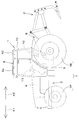
- a connecting portion 8 composed of a three-point link mechanism or the like.
- the connecting portion 8 is a lifting device.
- the working device 2 is attachable to and detachable from the lifting device. Thereby, the traveling vehicle 3 can connect the work device 2.
- the work device 2 can be pulled by the traveling vehicle 3. That is, the work device 2 for performing work is connected to the rear portion of the traveling vehicle 3.
- the working device 2 is a digging device for digging potatoes or carrots, a cultivating device for cultivating, a fertilizer spraying device for spraying fertilizer, a pesticide spraying device for spraying pesticides, a harvesting device for harvesting, cutting grass etc.
- FIG. 9 shows an example in which a digging device is attached to the traveling vehicle 3 as the working device 2.
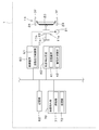
- the tractor 1 includes a steering device 11.
- the steering device 11 includes a steering wheel (steering wheel) 11a, a rotating shaft (steering shaft) 11b that rotates with the rotation of the steering wheel 11a, and an auxiliary mechanism (power steering mechanism) 11c that assists steering of the steering wheel 11a.
- the auxiliary mechanism 11c includes a hydraulic pump 21, a control valve 22 to which hydraulic oil discharged from the hydraulic pump 21 is supplied, and a steering cylinder 23 operated by the control valve 22.
- the control valve 22 is a solenoid valve that operates based on a control signal.
- the control valve 22 is, for example, a three-position switching valve that can be switched by moving a spool or the like.
- the control valve 22 can also be switched by steering the steering shaft 11b.
- the steering cylinder 23 is connected to an arm (knuckle arm) 24 that changes the direction of the front wheels 7F.
- the steering device 11 described above is an example, and the present invention is not limited to the configuration described above.
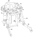
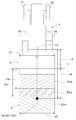
- the lifting device includes a lift arm 8a, a lower link 8b, a top link 8c, a lift rod 8d, and a lift cylinder 8e.
- a front end portion of the lift arm 8a is supported by a rear upper portion of a case (transmission case) accommodating the transmission 5 so as to be swingable upward or downward.
- the lift arm 8a swings (moves up and down) by driving the lift cylinder 8e.
- the lift cylinder 8e is composed of a hydraulic cylinder.
- the lift cylinder 8e is connected to the hydraulic pump 21 via the control valve 22.
- the control valve 22 is an electromagnetic valve or the like, and expands and contracts the lift cylinder 8e.
- the front end of the lower link 8b is supported by the lower rear portion of the transmission 5 so as to be swingable upward or downward.
- the front end portion of the top link 8c is swingably supported above or below the rear portion of the transmission 5 above the lower link 8b.
- the lift rod 8d connects the lift arm 8a and the lower link 8b.
- the working device 2 is connected to the rear portion of the lower link 8b and the rear portion of the top link 8c.
- the lift cylinder 8e is driven (expanded and contracted)
- the lift arm 8a moves up and down
- the lower link 8b connected to the lift arm 8a via the lift rod 8d moves up and down.
- the working device 2 swings (elevates) upward or downward with the front portion of the lower link 8b as a fulcrum.
- the tractor 1 includes a position detection device 40.
- the position detection device 40 is a device that detects the position of the traveling vehicle 3.
- the position detection device 40 is, for example, the positioning device 40.
- the positioning device 40 can detect its own position (positioning information including latitude and longitude) by a satellite positioning system (positioning satellite) such as D-GPS, GPS, GLONASS, Hokuto, Galileo, and Michibiki. That is, the positioning device 40 receives the satellite signal (position of the positioning satellite, transmission time, correction information, etc.) transmitted from the positioning satellite, and based on the satellite signal, the position of the tractor 1 (for example, latitude, longitude), That is, the vehicle body position W1 is detected.
- a satellite positioning system positioning system
- the positioning device 40 receives the satellite signal (position of the positioning satellite, transmission time, correction information, etc.) transmitted from the positioning satellite, and based on the satellite signal, the position of the tractor 1 (for example, latitude, longitude), That is, the vehicle body position W1
- the positioning device 40 includes a reception device 41 and an inertial measurement device (IMU: Inertial Measurement Unit) 42.
- the receiving device 41 is a device that has an antenna or the like and receives a satellite signal transmitted from a positioning satellite, and is attached to the traveling vehicle 3 separately from the inertial measurement device 42.
- the receiving device 41 is attached to the upper portion (roof 9a) of the cabin 9 provided in the traveling vehicle 3. Note that the mounting location of the receiving device 41 is not limited to the embodiment.
- the inertial measurement device 42 has an acceleration sensor that detects acceleration, a gyro sensor that detects angular velocity, and the like.
- the roll angle, pitch angle, yaw angle, etc. of the traveling vehicle 3 can be detected by the inertial measurement device 42 provided below the driver's seat 10.
- the position detection device 40 is the positioning device 40 that detects the position of the traveling vehicle 3 based on the satellite signal.
- the position detection device 40 can detect the position of the traveling vehicle 3
- the position of the traveling vehicle 3 may be detected based on the acceleration detected by the inertial measurement device 42 and predetermined position information, and the configuration is not limited to the above.
- the tractor 1 includes a control device 60 and a storage unit 62.
- the control device 60 is a device that controls a traveling system, a work system, and the like in the tractor 1.
- the storage unit 62 is a non-volatile memory or the like, and stores various information regarding control of the control device 60.
- the control device 60 has an automatic travel control unit 61 that controls the automatic travel of the tractor 1.
- the automatic travel control unit 61 is composed of an electric/electronic circuit provided in the control device 60, a program stored in a CPU, and the like. When starting the automatic traveling, the automatic traveling control unit 61 controls the control valve 22 of the steering device 11 so that the traveling vehicle 3 travels along the planned traveling route L.
- FIG. 3A shows an example of a planned traveling route L of the tractor.
- the planned travel route L includes a straight traveling portion L1 that causes the tractor 1 to travel straight, and a turning portion L2 that causes the tractor 1 to turn.
- the automatic traveling control unit 61 controls different traveling speeds of the straight traveling portion L1 and the turning portion L2. For example, in the straight traveling section L1, the automatic traveling control section 61 sets the traveling speed to the speed ⁇ .
- the automatic traveling control unit 61 sets the traveling speed to a speed ⁇ ( ⁇ > ⁇ ) slower than the speed ⁇ .
- the automatic traveling control unit 61 may divide the straight traveling portion L1 into a plurality of sections and set different traveling speeds for the respective sections, and the control of the traveling speed is not limited to the above configuration.
- the automatic traveling control unit 61 causes the steering shaft (rotating shaft) to rotate. ) Maintain the rotation angle of 11b.
- the automatic traveling control unit 61 determines that the steering direction of the tractor 1 is The steering shaft 11b is rotated so as to be in the right direction.
- the automatic travel control unit 61 determines that the steering direction of the tractor 1 is The steering shaft 11b is rotated so as to be in the left direction.
- the steering angle of the steering device 11 is changed based on the deviation between the vehicle body position W1 and the planned traveling route L, but the azimuth of the planned traveling route L and the tractor 1 (traveling vehicle 3).
- the automatic traveling control unit 61 sets the angle ⁇ g to zero (The steering angle may be set such that the vehicle body direction F1 matches the direction of the planned travel route L). Further, the automatic travel control unit 61 sets the final steering angle in the automatic steering based on the steering angle obtained based on the deviation (positional deviation) and the steering angle obtained based on the azimuth (azimuth deviation). May be.
- the setting of the steering angle in the automatic steering in the above-described embodiment is an example, and the setting is not limited.
- the control device 60 allows the tractor 1 (traveling vehicle 3) to automatically travel.
- the tractor 1 changes the traveling speed according to the relative distance between the worker M1 and the work machine M2 who work behind the work device 2 connected to the tractor 1 so as to perform automatic traveling.
- the relative distance can be maintained within a certain range.
- the worker M1 follows the tractor 1 and moves while following the work performed by the work device 2.
- the working device 2 is a digging device as shown in FIG. 9, the worker M1 picks up or harvests a crop as an auxiliary work.
- the work machine M2 moves while following the tractor 1 and assists the work performed by the work device 2. As shown in FIG.
- the automatic travel control unit 61 controls the travel speed corresponding to the planned travel route L, and based on the relative distance between the work device 2 and the work body M that works behind the work device 2. To change the traveling speed.
- the work vehicle 1 includes a distance detection unit 70. As shown in FIG. 9, the distance detection unit 70 is provided, for example, at the rear of the traveling vehicle 3 and detects the relative distance (detection distance x2) between the work device 2 and the work body M.
- the distance detection unit 70 is, for example, a laser scanner that detects the work body M behind the work device 2 and detects the distance to the work body M.
- the laser scanner has a detection angle of about 270 degrees behind the traveling vehicle 3 and can detect the work body M located behind the work device 2. As shown in FIG. 4, the laser scanner can detect the work M in at least the target area E on the plane.
- the distance detection unit 70 is a laser scanner, but the distance detection unit 70 only needs to be able to detect the relative distance between the work device 2 and the work body M behind the work device 2, for example, It may be a radar sensor, a sonar sensor, or the like, or may be an imaging device that images the rear of the work device 2 and detects the relative distance.
- the target area E includes at least an area that overlaps with the area in which the work device 2 works. More specifically, one end (left end) in the width direction of the target region E is located at the same side or one side (left side) as one end (left end) of the region in which the work device 2 operates, The other end (right end) in the width direction of the target region E is located at the same side or the other side (right side) as the other end (right end) of the region in which the work device 2 operates.
- the width y2 in the width direction of the target area E is the same as or longer than y1 in the width direction of the area in which the work device 2 operates (y2 ⁇ y1). In the present embodiment, as shown in FIG.
- the left end in the width direction of the target region E coincides with the left end of the region in which the work device 2 performs work
- the right end in the width direction of the target region E is the work device. 2 coincides with the right edge of the working area.
- the distance detection unit 70 includes a detection unit 71 that detects the work body M, and a processing unit 72 that processes detection information from the detection unit 71.
- the detection unit 71 detects the work body M closest to the detection unit 71 among the work bodies M located in the target area E.
- the detection unit 71 irradiates the target area E with a laser beam and receives the reflected light of the laser beam reflected by the target area E.
- the processing unit 72 detects the detection distance x2 between the work device 2 and the work body M based on the time from the irradiation start of the detection unit 71 to the light reception.
- the processing unit 72 detects the relative distance x between the traveling vehicle 3 and the work body M based on the time from the irradiation start to the light reception of the detection unit 71, and the traveling vehicle 3 and the working device 2 are detected.
- the relative distance x1 is a value set in advance corresponding to the work device 2, and is included in the processing unit 72.
- the relative distance x1 is set by operating a mobile terminal such as a computer such as a personal computer (PC), a smartphone (multifunctional mobile phone), a tablet, or the like that is communicably connected to the tractor 1 or a display device provided in the tractor 1. By doing so, an operator (operator) or the like may change the setting of the value, or may automatically change the setting corresponding to the work device 2 connected to the connecting portion 8.
- the processing unit 72 outputs the processed detection distance x2 to the automatic travel control unit 61.
- the distance detector 70 is attached to the upper rear part of the cabin 9. Specifically, the detection unit 71 is provided below the roof 9a of the cabin 9 so as to face rearward and downward. The distance detection unit 70 is provided at the center of the lower portion of the roof 9a in the width direction. In the present embodiment, the distance detecting unit 70 is attached to the upper rear portion of the cabin 9, but the distance detecting unit 70 only needs to be able to detect the detection distance x2 between the work device 2 and the work body M, It may be attached to a pillar included in the cabin 9 or may be attached to the work device 2.
- the automatic travel control unit 61 automatically changes the gear position of the transmission 5, the rotation speed of the prime mover 4, etc. according to the detected distance x2, and changes the vehicle speed (travel speed) of the tractor 1 (traveling vehicle 3). Specifically, the automatic traveling control unit 61 automatically determines the gear position of the transmission 5, the rotation speed of the prime mover 4, and the like according to a plurality of areas obtained by dividing the target area E according to the distance from the work device 2. To change the traveling speed of the traveling vehicle 3.
- the plurality of areas are a first area (stop area) E1, a second area (deceleration area) E2, a third area (speed maintenance area) E3, a fourth area (acceleration area) E4, and a fifth area ( Stop area) E5 is included. As shown in FIG.
- the target area E is divided into a first area E1, a second area E2, a third area E3, a fourth area E4, and a fifth area E5 in order from the area far from the work device 2.
- the first area E1, the second area E2, the third area E3, the fourth area E4, and the fifth area E5 are divided by a preset range or threshold.
- the range and the threshold are ranges or thresholds corresponding to the detection distance x2, and are stored in advance in the storage unit 62 provided in the traveling vehicle 3, for example.
- the storage unit 62 stores, for example, a predetermined range, a first threshold P3, and a second threshold P4 as preset ranges or thresholds.
- the predetermined range is a range defined by the upper limit value P1 and the lower limit value P2.
- the first threshold value P3 is a value larger than the upper limit value P1
- the second threshold value P4 is a value smaller than the first threshold value P3.
- the second threshold P4 is a value smaller than the first threshold P3 and smaller than the lower limit P2.
- the first area E1 is an area in which the detection distance x2 is equal to or larger than the first threshold P3 (x ⁇ P3).
- the second area E2 is an area in which the detection distance x2 is less than the first threshold value P3 and is not less than the upper limit value P1 (P3>x ⁇ P1).
- the second region E2 is a region sandwiched between the first threshold P3 and the upper limit P1 (predetermined range).
- the third area E3 is an area in which the detection distance x2 is less than the upper limit value P1 and exceeds the lower limit value P2 (P1>x>P2).
- the third region E3 is a region sandwiched between the upper limit value P1 and the lower limit value P2 and coincides with a predetermined range.
- the fourth area E4 is an area in which the detection distance x2 is equal to or less than the lower limit value P2 and exceeds the second threshold value P4 (P2 ⁇ x>P4).
- the fourth region E4 is a region sandwiched between the lower limit P2 and the second threshold P4 (predetermined range).
- the fifth area E5 is an area in which the detection distance x2 is equal to or less than the second threshold value P4 (x ⁇ P4).
- the automatic travel control unit 61 acquires a predetermined range, the first threshold P3, and the second threshold P4 from the storage unit 62, and the predetermined range, the first threshold P3, and the second threshold P4, and the distance detection unit 70. The traveling speed is changed based on the detected distance x2 output from
- the predetermined range (upper limit value P1 and lower limit value P2), the first threshold value P3, and the second threshold value P4 are preset predetermined values, which are stored in the storage unit 62 and are stored in the automatic traveling control unit. Although it is possessed by the 61 acquired from the storage unit 62, the automatic traveling control unit 61 may have a predetermined range, a first threshold P3, and a second threshold P4 in advance, and the acquisition source is The configuration is not limited to the above. Further, the predetermined range, the first threshold P3, and the second threshold P4 may be changed arbitrarily.
- the predetermined range, the first threshold value P3, and the second threshold value P4 can be changed by using a portable computer such as a personal computer (PC), a smartphone (multifunctional mobile phone), or a tablet that is communicably connected to the tractor 1. This is performed by operating the terminal or the display device provided in the tractor 1. Further, in the present embodiment, the automatic travel control unit 61 changes the traveling speed according to a plurality of areas into which the target area E is divided according to the distance from the work device 2, but the distance from the work device 2 is changed. The traveling speeds may be changed accordingly, and the shapes of the plurality of regions are not limited to the substantially rectangular shape shown in FIG. 4, and may be substantially fan-shaped or trapezoidal, and are not limited to the above configuration.
- a portable computer such as a personal computer (PC), a smartphone (multifunctional mobile phone), or a tablet that is communicably connected to the tractor 1. This is performed by operating the terminal or the display device provided in the tractor 1.
- the automatic travel control unit 61 changes the traveling speed according to a plurality of
- the control of the automatic driving control unit 61 will be described below.
- the automatic traveling control unit 61 changes the traveling speed to zero or increases when the detected distance x2 is within a predetermined range, and changes the traveling speed when the detected distance x2 is within a predetermined range. If the detected distance x2 is equal to or larger than the predetermined range, the traveling speed is changed to be reduced. Specifically, the automatic traveling control unit 61 changes the traveling speed to zero when the detected distance x2 is equal to or larger than the predetermined range and is equal to or larger than the first threshold P3.
- the automatic travel control unit 61 changes the traveling speed to zero, and the detected distance x2 is equal to or less than the predetermined range and 2 If the threshold value P4 is exceeded, the traveling speed is changed to be increased.
- the control of the automatic travel control unit 61 will be described in more detail.
- the automatic travel control unit 61 sets the traveling speed to zero. Change to.
- the automatic traveling control unit 61 stops the traveling vehicle 3 by controlling the braking device that brakes the front wheels 7F or the rear wheels 7R and the transmission 5. Accordingly, when the relative distance between the work device 2 and the work body M becomes relatively large, the traveling of the traveling vehicle 3 can be stopped. Therefore, when the work body M is not moving, such as when the work is suspended, the work vehicle 1 precedes the work regardless of the work body M without performing a stop operation or the like on the traveling vehicle 3. It is possible to suppress doing.
- the automatic traveling control unit 61 changes so as to reduce the traveling speed corresponding to the planned traveling route L. To do.
- the automatic traveling control unit 61 lowers the shift speed of the transmission 5, reduces the rotation speed of the prime mover 4, brakes the front wheels 7F or the rear wheels 7R by a braking device that brakes the front wheels 7F or the rear wheels 7R, and the like.
- the traveling speed is reduced in inverse proportion to the length of the distance x2. Specifically, for example, as shown in FIG. 5, the automatic travel control unit 61 multiplies the travel speed corresponding to the planned travel route L by the correction value set according to the length of the detected distance x2.
- the automatic traveling control unit 61 changes the traveling speed so as to reduce the traveling speed when the relative distance to the work body M is relatively large in the automatic traveling. Therefore, it is possible to maintain a predetermined relative distance between the work device 2 and the work body M without performing a stop operation or the like on the traveling vehicle 3, and the work of the work body M is delayed with respect to the work of the work device 2. Can be suppressed.
- the automatic travel control unit 61 reduces the traveling speed in inverse proportion to the length of the detection distance x2, but the detection distance x2 is less than the first threshold value P3 and exceeds the upper limit value P1. In this case, the automatic traveling control unit 61 may reduce the traveling speed corresponding to the planned traveling route L and may reduce the traveling speed corresponding to the traveling planned route L by a constant speed.
- the automatic traveling control unit 61 does not change the traveling speed from the traveling speed corresponding to the planned traveling route L. .. In other words, when the detected distance x2 is within the predetermined range, the automatic traveling control unit 61 maintains the traveling speed without changing the traveling speed from the traveling speed corresponding to the planned traveling route L.
- the automatic traveling control unit 61 makes the traveling speed corresponding to the planned traveling route L higher than the traveling speed. change.
- the automatic travel control unit 61 increases the traveling speed in inverse proportion to the length of the detection distance x2, but the detection distance x2 is equal to or lower than the lower limit value P2 and exceeds the second threshold value P4. In this case, the automatic traveling control unit 61 may increase the traveling speed corresponding to the planned traveling route L, or may increase the traveling speed by a constant speed.
- the automatic traveling control unit 61 changes the traveling speed to zero.
- the automatic traveling control unit 61 stops the traveling vehicle 3 by controlling the braking device and the transmission 5. Thereby, when the relative distance between the work device 2 and the work body M is relatively small, the traveling of the traveling vehicle 3 can be stopped. For this reason, it is possible to prevent the work body M from approaching the vicinity of the work vehicle 1 that is automatically traveling, hindering the work vehicle M from contacting the work vehicle 1 and contacting the work vehicle M with the work vehicle 1.
- the relative distance can be kept constant, and the work vehicle 1
- the work body M can continue the work without performing a stop operation or the like on the work vehicle 1 in accordance with the work body M performing the work. Further, even if the work vehicle 1 is not stopped, the work device 2 and the work body M can be maintained at a predetermined relative distance, and the work efficiency is improved by reducing the stop frequency of the work vehicle 1. You can
- the automatic traveling control unit 61 starts the automatic traveling of the tractor 1 (S1).
- the control device 60 acquires an instruction to start automatic travel from a mobile terminal such as a computer such as a personal computer (PC), a smartphone (multifunctional mobile phone), or a tablet that is communicatively connected to the tractor 1.
- a mobile terminal such as a computer such as a personal computer (PC), a smartphone (multifunctional mobile phone), or a tablet that is communicatively connected to the tractor 1.
- the control device 60 may start the automatic traveling by acquiring a start instruction at a predetermined time, and the acquisition source of the start instruction is not limited to the above configuration.
- the automatic traveling control unit 61 controls the control valve 22 of the steering device 11 so that the traveling vehicle 3 travels along the planned traveling route L. Further, when the automatic traveling is started, the automatic traveling control unit 61 controls the vehicle speed (traveling speed) of the tractor 1 by automatically changing the gear position of the transmission 5, the rotation speed of the prime mover 4, and the like.
- the distance detecting unit 70 detects the detected distance x2 (S2). Specifically, the detection unit 71 of the distance detection unit 70 detects the work body M closest to the detection unit 71 among the work bodies M located in the target area E. The detection unit 71 irradiates the target area E with a laser beam and receives the reflected light of the laser beam reflected by the target area E. The processing unit 72 of the distance detection unit 70 detects the detection distance x2 between the work device 2 and the work body M based on the time from the irradiation start to the light reception of the detection unit 71.
- the processing unit 72 detects the relative distance x between the traveling vehicle 3 and the work body M based on the time from the irradiation start to the light reception of the detection unit 71, and the traveling vehicle 3 and the working device 2 are detected.
- the detection distance x2 is detected by subtracting the relative distance x1 between and.
- the processing unit 72 outputs the processed detection distance x2 to the automatic travel control unit 61.
- the automatic traveling control unit 61 automatically changes the gear position of the transmission 5, the rotation speed of the prime mover 4, and the like according to the detection distance x2, and the tractor.
- the vehicle speed (running speed) of 1 is changed (S3 to S11).
- the automatic travel control unit 61 first acquires the first threshold value P3 from the storage unit 62, and confirms whether the detected distance x2 output from the distance detection unit 70 is equal to or greater than the first threshold value P3. (S3).
- the automatic traveling control unit 61 changes the traveling speed to zero (S4).
- the automatic travel control unit 61 changes the travel speed to zero.
- the automatic traveling control unit 61 stops the traveling vehicle 3 by controlling the braking device that brakes the front wheels 7F or the rear wheels 7R and the transmission 5.
- the automatic travel control unit 61 acquires the upper limit value P1 from the storage unit 62, and the detection distance x2 output from the distance detection unit 70 is the upper limit value. It is confirmed whether it is P1 or more (S5).
- the automatic travel control unit 61 changes the travel speed to be slower than the travel speed corresponding to the planned travel route L (S6). That is, when the work body M closest to the detection unit 71 is located in the second area E2, in other words, the detection distance x2 is less than the first threshold value P3, and the automatic traveling control unit 61 sets a predetermined value.
- the automatic traveling control unit 61 lowers the shift speed of the transmission 5, reduces the rotation speed of the prime mover 4, brakes the front wheels 7F or the rear wheels 7R by a braking device that brakes the front wheels 7F or the rear wheels 7R, and the like.
- the traveling speed is reduced in inverse proportion to the length of the distance x2.
- the automatic travel control unit 61 acquires the lower limit value P2 from the storage unit 62, and the detected distance x2 output from the distance detection unit 70 is the lower limit value P2. It is confirmed whether or not is exceeded (S7).
- the automatic travel control unit 61 does not change the travel speed from the travel speed corresponding to the planned travel route L (S8). That is, when the work body M closest to the detection unit 71 is located in the third area E3, in other words, when the detection distance x2 is within a predetermined range, the automatic travel control unit 61 corresponds to the planned travel route L.
- the running speed is maintained without changing the running speed from the running speed.
- the automatic travel control unit 61 acquires the second threshold value P4 from the storage unit 62, and the detection distance x2 output from the distance detection unit 70 is It is confirmed whether or not the second threshold P4 is exceeded (S9).
- the automatic travel control unit 61 changes the speed so as to be higher than the travel speed corresponding to the planned travel route L (S10). That is, when the work body M closest to the detection unit 71 is located in the fourth area E4, in other words, the detection distance x2 is less than or equal to a preset predetermined range and exceeds the second threshold P4.
- the automatic traveling control unit 61 changes the traveling speed to be increased.
- the automatic travel control unit 61 increases the speed of the transmission 5, increases the number of revolutions of the prime mover 4, etc., and increases the travel speed in inverse proportion to the length of the detection distance x2.
- the automatic travel control unit 61 changes the traveling speed to zero ( S11). In other words, when the work body M closest to the detection unit 71 is located in the fifth area E5, the automatic traveling control unit 61 changes the traveling speed to zero.
- the automatic traveling control unit 61 stops the traveling vehicle 3 by controlling the braking device and the transmission 5.
- the above-described work vehicle 1 includes the traveling vehicle 3 to which the work device 2 can be connected, the position detecting device 40 that detects the position of the traveling vehicle 3, the position of the traveling vehicle 3 detected by the position detecting device 40, and the planned traveling route L.
- the automatic traveling control unit 61 that automatically steers the traveling vehicle 3 and controls the traveling speed of the traveling vehicle 3 corresponding to the planned traveling route L, the working device 2, and the rear of the working device 2.
- the distance detection unit 70 that detects the detection distance x2 between the worker M1 who works and the automatic traveling control unit 61 changes the traveling speed based on the detection distance x2.
- the automatic traveling control unit 61 can change the traveling speed of the traveling vehicle 3 according to the position of the worker M1 who works behind the work device 2. Therefore, the relative distance between the work device 2 and the worker M1 is appropriately maintained, cooperation between the work vehicle 1 and the work of the worker M1 is easily realized, and the automatic traveling speed of the work vehicle 1 is slowed in advance. The work can be continued without setting or starting or stopping the work vehicle 1.
- the position detecting device 40 that detects the position of the traveling vehicle 3, the position of the traveling vehicle 3 detected by the position detecting device 40, and the planned traveling route L
- An automatic traveling control unit 61 that automatically steers the traveling vehicle 3 and controls the traveling speed of the traveling vehicle 3 corresponding to the planned traveling route L, the work device 2, and a work machine that performs work behind the work device 2.
- M2 and the distance detection unit 70 that detects the detection distance x2 between the M2 and the automatic traveling control unit 61 change the traveling speed based on the detection distance x2.
- the automatic travel control unit 61 can change the traveling speed of the traveling vehicle 3 according to the position of the work machine M2 that works behind the work device 2. Therefore, the relative distance between the work device 2 and the work machine M2 is appropriately maintained, the work of the work vehicle 1 and the work machine M2 can be easily linked, and the speed of automatic traveling of the work vehicle 1 is reduced in advance. The work can be continued without setting or starting or stopping the work vehicle 1.
- the automatic traveling control unit 61 changes the traveling speed to zero or speeds up when the detection distance x2 is equal to or less than a preset predetermined range, and when the detection distance x2 is within the predetermined range. If the detected distance x2 is equal to or larger than the predetermined range without changing the traveling speed, the traveling speed is changed to be reduced. According to the above configuration, when the relative distance to the work body M (worker M1 or work machine M2) is small in the automatic travel, the automatic travel control unit 61 increases the traveling speed, and the automatic travel control unit 61 When the relative distance is large, the traveling speed is changed to be reduced.
- the automatic travel control unit 61 has a first threshold value P3 that is larger than a predetermined range, and changes the travel speed to zero when the detection distance x2 is equal to or greater than the predetermined range and equal to or greater than the first threshold value P3. To do. According to the above configuration, when the relative distance between the work device 2 and the work body M becomes relatively large, the traveling of the work device 2 can be stopped. Therefore, when the work body M is not moving, such as when the work body is interrupted, it is possible to suppress the work vehicle 1 from preceding the work regardless of the work of the work body M.
- the automatic travel control unit 61 has a second threshold value P4 smaller than a predetermined range, and changes the travel speed to zero when the detected distance x2 is equal to or less than the predetermined range and equal to or less than the second threshold value P4. Then, when the detected distance x2 is equal to or less than the predetermined range and exceeds the second threshold value P4, the traveling speed is changed to be increased. According to the above configuration, the automatic traveling control unit 61 increases the traveling speed when the relative distance to the work body M is small in the automatic traveling. The relative distance can be maintained, and the work of the work body M can be prevented from being delayed with respect to the work of the work device 2.
- the work vehicle 1 of the second embodiment will be described focusing on the configuration different from the above-described embodiment (first embodiment), and the same components as those of the first embodiment will be denoted by the same reference numerals and detailed description will be given. Omit it.
- the work vehicle 1 of the first embodiment automatically changes the gear position of the transmission 5, the rotation speed of the prime mover 4, and the like according to the detected distance x2 to increase or decrease the vehicle speed (running speed) of the tractor 1.
- the work vehicle 1 according to the second embodiment automatically changes the gear position of the transmission 5, the rotation speed of the prime mover 4, and the like according to the detected distance x2 to maintain or change the vehicle speed (running speed) of the tractor 1 to zero. ..
- the automatic travel control in the second embodiment will be described in detail.
- the automatic traveling control unit 61 maintains or changes the vehicle speed (traveling speed) of the tractor 1 to zero according to a plurality of areas obtained by dividing the target area E according to the distance from the work device 2.
- the plurality of areas include a first area (stop area) E1a, a second area (speed maintaining area) E2a, and a third area (stop area) E3a.
- the target region E is divided into a first region E1a, a second region E2a, and a third region E3a in order from a region far from the work device 2.
- the first area E1a, the second area E2a, and the third area E3a are divided by a preset range or threshold.
- the threshold and range are, for example, a first threshold P3 and a second threshold P4.
- the first threshold P3 and the second threshold P4 are stored in the storage unit 62, the first threshold P3 is a preset value, and the second threshold P4 is a value smaller than the first threshold P3. ..
- the first area E1a is an area in which the detection distance x2 is equal to or larger than the first threshold P3.
- the second area E2a is an area in which the detection distance x2 is less than the first threshold P3 and exceeds the second threshold P4.
- the second region E2a is a region sandwiched between the first threshold P3 and the second threshold P4.
- the third area E3a is an area in which the detection distance x2 is equal to or less than the second threshold value P4.
- the automatic travel control unit 61 acquires the first threshold value P3 and the second threshold value P4 from the storage unit 62, and outputs the first threshold value P3 and the second threshold value P4 to the detection distance x2 output from the distance detection unit 70. Based on this, the traveling speed is maintained or changed to zero.
- the automatic traveling control unit 61 changes the traveling speed to zero when the detected distance x2 is equal to or larger than the first threshold value P3.
- the automatic traveling control unit 61 changes the traveling speed to zero when the detected distance x2 is equal to or less than the second threshold value P4.
- the control of the automatic travel control unit 61 will be described in detail.
- the automatic traveling control unit 61 stops the traveling vehicle 3 by controlling the braking device that brakes the front wheels 7F or the rear wheels 7R and the transmission 5.
- the automatic traveling control unit 61 When the work body M closest to the detection unit 71 is located in the second area E2a (P3>x>P4), the automatic traveling control unit 61 does not change the traveling speed from the traveling speed corresponding to the planned traveling route L. .. That is, when the detected distance x2 is less than the first threshold P3 and exceeds the second threshold P4, the automatic traveling control unit 61 does not change the traveling speed from the traveling speed corresponding to the planned traveling route L and travels. Maintain speed.
- the automatic traveling control unit 61 changes the traveling speed to zero.
- the automatic traveling control unit 61 stops the traveling vehicle 3 by controlling the braking device and the transmission 5. Thereby, when the relative distance between the work device 2 and the work body M is relatively small, the traveling of the traveling vehicle 3 can be stopped. For this reason, it is possible to prevent the work body M from approaching the vicinity of the work vehicle 1 that is automatically traveling, hindering the work vehicle M from contacting the work vehicle 1 and contacting the work vehicle M with the work vehicle 1.
- the automatic traveling control unit 61 starts the automatic traveling of the tractor 1 (S21).
- the control device 60 is acquired from a portable terminal such as a computer such as a personal computer (PC), a smartphone (multifunctional mobile phone), a tablet, or the like that is communicably connected to the tractor 1.
- the automatic traveling control unit 61 controls the control valve 22 of the steering device 11 so that the traveling vehicle 3 travels along the planned traveling route L.
- the automatic traveling control unit 61 controls the vehicle speed (traveling speed) of the tractor 1 by automatically changing the gear position of the transmission 5, the rotation speed of the prime mover 4, and the like.
- the distance detection unit 70 detects the detected distance x2 (S22).
- the detection unit 71 of the distance detection unit 70 detects the work body M closest to the detection unit 71 among the work bodies M located in the target area E.
- the detection unit 71 irradiates the target area E with a laser beam and receives the reflected light of the laser beam reflected by the target area E.
- the processing unit 72 of the distance detection unit 70 detects the detection distance x2 between the work device 2 and the work body M based on the time from the irradiation start to the light reception of the detection unit 71.
- the processing unit 72 detects the relative distance x between the traveling vehicle 3 and the work body M based on the time from the irradiation start to the light reception of the detection unit 71, and the traveling vehicle 3 and the working device 2 are detected.
- the detection distance x2 is detected by subtracting the relative distance x1 between and.
- the processing unit 72 outputs the processed detection distance x2 to the automatic travel control unit 61.
- the automatic traveling control unit 61 automatically changes the gear position of the transmission 5, the rotation speed of the prime mover 4, and the like according to the detection distance x2, and the traveling speed Is maintained or changed to zero (S23 to S27). Specifically, the automatic travel control unit 61 first acquires the first threshold value P3 from the storage unit 62, and confirms whether the detected distance x2 output from the distance detection unit 70 is equal to or greater than the first threshold value P3. (S23). When the detected distance x2 is equal to or greater than the first threshold P3 (S23, Yes), the automatic travel control unit 61 changes the travel speed to zero (S24).
- the automatic traveling control unit 61 changes the traveling speed to zero.
- the automatic traveling control unit 61 stops the traveling vehicle 3 by controlling the braking device that brakes the front wheels 7F or the rear wheels 7R and the transmission 5.
- the automatic travel control unit 61 acquires the second threshold P4 from the storage unit 62, and the detection distance x2 output from the distance detection unit 70 is the second. 2 It is confirmed whether or not the threshold value P4 is exceeded (S25). If the detected distance x2 exceeds the second threshold value P4, the automatic travel control unit 61 does not change the travel speed from the travel speed corresponding to the planned travel route L (S26). That is, when the working body M closest to the detection unit 71 is located in the second area E2a, in other words, when the detected distance x2 is less than the first threshold value P3 and exceeds the second threshold value P4, the automatic traveling control is performed. The unit 61 maintains the traveling speed without changing the traveling speed from the traveling speed corresponding to the planned traveling route L.
- the automatic travel control unit 61 changes the traveling speed to zero ( S27). In other words, when the work body M closest to the detection unit 71 is located in the third area E3a, the automatic traveling control unit 61 changes the traveling speed to zero.
- the automatic traveling control unit 61 stops the traveling vehicle 3 by controlling the braking device and the transmission 5.
- the above-described automatic travel control unit 61 changes the travel speed to zero when the detected distance x2 is equal to or greater than the first threshold P3. According to the above configuration, the traveling of the traveling vehicle 3 can be stopped when the relative distance between the work body M (the worker M1 or the work machine M2) and the work device 2 is large. Therefore, it is possible to prevent the work vehicle 1 from performing the work regardless of the work of the work body M when the work body M is not moving, such as when the work is suspended.
- the automatic traveling control unit 61 changes the traveling speed to zero when the detected distance x2 is equal to or less than the second threshold P4 which is smaller than the first threshold P3. According to the above configuration, the traveling of the traveling vehicle 3 can be stopped when the relative distance between the work body M and the work device 2 is small. Therefore, it is possible to prevent the work body M from approaching the vicinity of the work vehicle 1 that is automatically traveling, and hindering the work vehicle M from coming into contact with the work vehicle 1.
Abstract
作業の連携を容易に実現し、作業を継続する。 作業車両(1)は、作業装置(2)を連結可能な走行車両(3)と、走行車両(3)の位置を検出する位置検出装置(40)と、位置検出装置(40)が検出した走行車両(3)の位置と走行予定ルートとに基づいて、走行車両(3)の自動操舵を行い、走行予定ルート(L1)に対応する走行車両(3)の走行速度の制御を行う自動走行制御部(61)と、作業装置(2)と、当該作業装置(2)の後方で作業を行う作業者(M1)と、の間の検出距離(x)を検出する距離検出部(70)と、を備え、自動走行制御部(61)は、走行速度を検出距離(x)に基づいて変更する。
Description
本発明は、自動走行が可能なトラクタ等の作業車両に関する。
従来、特許文献1に開示された作業車両協調システムが知られている。
特許文献1に開示された作業車両協調システムは、無人操縦可能な子作業車両と有人操縦される親作業車両とにより、対地作業を行う作業車両協調システムであり、親作業車両の位置を検出する親位置検出モジュールと、子作業車両の位置を検出する子位置検出モジュールと、親作業車両の作業走行軌跡に基づいて子作業車両の無人操縦走行のために用いられる走行予定ルートを算定する経路算定部と、子作業車両位置と走行予定ルートとに基づいて子作業車両を親作業車両に追従するように無人操縦する操縦制御部と、を備えている。
特許文献1に開示された作業車両協調システムは、無人操縦可能な子作業車両と有人操縦される親作業車両とにより、対地作業を行う作業車両協調システムであり、親作業車両の位置を検出する親位置検出モジュールと、子作業車両の位置を検出する子位置検出モジュールと、親作業車両の作業走行軌跡に基づいて子作業車両の無人操縦走行のために用いられる走行予定ルートを算定する経路算定部と、子作業車両位置と走行予定ルートとに基づいて子作業車両を親作業車両に追従するように無人操縦する操縦制御部と、を備えている。
特許文献1の作業車両協調システムによれば、親作業者の走行軌跡を基準経路として利用することで、親作業車両と子作業車両とが同一の作業を行い、子作業車両が親作業車両の作業跡を所定量オーバーラップして作業する。このため、親作業車両と子作業車両とで効果的な連携によって、作業走行を実現することができる。
しかしながら、子作業車両が親作業車両の走行軌跡を走行する(追従する)ためには、親作業車両と子作業車両とで、それぞれの位置情報や走行予定ルートの通信を行う必要がある。このため、親作業車両と、当該親作業車両に追従して作業を行う作業車両や作業者とで通信手段がない場合には、親作業車両と子作業車両との相対距離を一定に保つことが困難であり、親作業車両との効果的な連携を実現することができなかった。
しかしながら、子作業車両が親作業車両の走行軌跡を走行する(追従する)ためには、親作業車両と子作業車両とで、それぞれの位置情報や走行予定ルートの通信を行う必要がある。このため、親作業車両と、当該親作業車両に追従して作業を行う作業車両や作業者とで通信手段がない場合には、親作業車両と子作業車両との相対距離を一定に保つことが困難であり、親作業車両との効果的な連携を実現することができなかった。
本発明は、このような従来技術の問題点を解決すべくなされたものであって、作業の連携を容易に実現することができる自動走行可能な作業車両の提供を目的とする。
本発明の一態様に係る作業車両は、作業装置を連結可能な走行車両と、前記走行車両の位置を検出する位置検出装置と、前記位置検出装置が検出した走行車両の位置と走行予定ルートとに基づいて、前記走行車両の自動操舵を行い、前記走行予定ルートに対応する前記走行車両の走行速度の制御を行う自動走行制御部と、前記作業装置と、当該作業装置の後方で作業を行う作業者と、の間の検出距離を検出する距離検出部と、を備え、前記自動走行制御部は、前記走行速度を前記検出距離に基づいて変更する。
また、作業車両は、作業装置を連結可能な走行車両と、前記走行車両の位置を検出する位置検出装置と、前記位置検出装置が検出した走行車両の位置と走行予定ルートとに基づいて、前記走行車両の自動操舵を行い、前記走行予定ルートに対応する前記走行車両の走行速度の制御を行う自動走行制御部と、前記作業装置と、当該作業装置の後方で作業を行う作業機械と、の間の検出距離を検出する距離検出部と、を備え、前記自動走行制御部は、前記走行速度を前記検出距離に基づいて変更する。
また、前記自動走行制御部は、前記検出距離が予め設定された所定の範囲以下である場合に、前記走行速度を零又は増速するよう変更し、前記検出距離が前記所定の範囲内にある場合に、前記走行速度を変更せず、前記検出距離が前記所定の範囲以上である場合に、前記走行速度を減速するよう変更する。
また、前記自動走行制御部は、前記所定の範囲よりも大きい第1閾値を有し、前記検出距離が前記所定の範囲以上であり且つ前記第1閾値以上である場合に、前記走行速度を零に変更する。
また、前記自動走行制御部は、前記所定の範囲よりも大きい第1閾値を有し、前記検出距離が前記所定の範囲以上であり且つ前記第1閾値以上である場合に、前記走行速度を零に変更する。
また、前記自動走行制御部は、前記所定の範囲よりも小さい第2閾値を有し、前記検出距離が前記所定の範囲以下であり且つ前記第2閾値以下である場合に、前記走行速度を零に変更し、前記検出距離が前記所定の範囲以下であり且つ前記第2閾値を超過している場合に、前記走行速度を増速するように変更する。
また、前記自動走行制御部は、前記検出距離が第1閾値以上である場合に、前記走行速度を零に変更する。
また、前記自動走行制御部は、前記検出距離が第1閾値以上である場合に、前記走行速度を零に変更する。
また、前記自動走行制御部は、前記検出距離が前記第1閾値よりも小さい第2閾値以下である場合に、前記走行速度を零に変更する。
上記作業車両によれば、作業の連携を容易に実現し、作業を継続することができる。
以下、本発明の実施の形態を図面に基づいて説明する。
[第1実施形態]
まず、作業車両1の1つであるトラクタについて説明する。図9に示すように、トラクタ1は、走行装置7を有する走行車両3と、原動機4と、変速装置5とを備えている。走行車両3にはキャビン9が設けられ、当該キャビン9内には運転席10が設けられている。以下の説明においては、作業車両1の運転席10に着座した運転者の前側(図9の矢印A1方向)を前方、運転者の後側(図9の矢印A2方向)を後方、運転者の左側(図9の手前側)を左方、運転者の右側(図9の奥側)を右方として説明する。また、前後方向に直交する方向である水平方向を幅方向として説明する。走行装置7は、前輪7F及び後輪7Rを有する装置である。前輪7Fは、タイヤ型であってもクローラ型であってもよい。また、後輪7Rも、タイヤ型であってもクローラ型であってもよい。原動機4は、ディーゼルエンジン、電動モータ等である。変速装置5は、変速によって走行装置7の推進力を切換可能であるとともに、走行装置7の前進、後進の切換が可能である。走行車両3にはキャビン9が設けられ、当該キャビン9内には運転席10が設けられている。
また、走行車両3の後部には、3点リンク機構等で構成された連結部8が設けられている。連結部8は、昇降装置である。昇降装置には、作業装置2が着脱可能である。これによって、走行車両3は、作業装置2を連結可能である。作業装置2を昇降装置に連結することによって、走行車両3によって作業装置2を牽引することができる。即ち、走行車両3の後部には、作業を行う作業装置2が連結されている。作業装置2は、芋や人参の掘り取りを行う掘り取り装置、耕耘する耕耘装置、肥料を散布する肥料散布装置、農薬を散布する農薬散布装置、収穫を行う収穫装置、牧草等の刈取を行う掘り取り装置、牧草等の拡散を行う拡散装置、牧草等の集草を行う集草装置、牧草等の成形を行う成形装置等である。なお、図9では、作業装置2として掘り取り装置を走行車両3に取り付けた例を示している。
図1に示すように、トラクタ1は、操舵装置11を備えている。操舵装置11は、ハンドル(ステアリングホイール)11aと、ハンドル11aの回転に伴って回転する回転軸(操舵軸)11bと、ハンドル11aの操舵を補助する補助機構(パワーステアリング機構)11cと、を有している。補助機構11cは、油圧ポンプ21と、油圧ポンプ21から吐出した作動油が供給される制御弁22と、制御弁22により作動するステアリングシリンダ23とを含んでいる。制御弁22は、制御信号に基づいて作動する電磁弁である。制御弁22は、例えば、スプール等の移動によって切り換え可能な3位置切換弁である。また、制御弁22は、操舵軸11bの操舵によっても切換可能である。ステアリングシリンダ23は、前輪7Fの向きを変えるアーム(ナックルアーム)24に接続されている。
したがって、ハンドル11aを操作すれば、当該ハンドル11aに応じて制御弁22の切換位置及び開度が切り換わり、当該制御弁22の切換位置及び開度に応じてステアリングシリンダ23が左又は右に伸縮することによって、前輪7Fの操舵方向を変更することができる。なお、上述した操舵装置11は一例であり、上述した構成に限定されない。
図2に示すように、昇降装置は、リフトアーム8a、ロアリンク8b、トップリンク8c、リフトロッド8d、リフトシリンダ8eを有している。リフトアーム8aの前端部は、変速装置5を収容するケース(ミッションケース)の後上部に上方又は下方に揺動可能に支持されている。リフトアーム8aは、リフトシリンダ8eの駆動によって揺動(昇降)する。リフトシリンダ8eは、油圧シリンダから構成されている。リフトシリンダ8eは、制御弁22を介して油圧ポンプ21と接続されている。制御弁22は、電磁弁等であって、リフトシリンダ8eを伸縮させる。
図2に示すように、昇降装置は、リフトアーム8a、ロアリンク8b、トップリンク8c、リフトロッド8d、リフトシリンダ8eを有している。リフトアーム8aの前端部は、変速装置5を収容するケース(ミッションケース)の後上部に上方又は下方に揺動可能に支持されている。リフトアーム8aは、リフトシリンダ8eの駆動によって揺動(昇降)する。リフトシリンダ8eは、油圧シリンダから構成されている。リフトシリンダ8eは、制御弁22を介して油圧ポンプ21と接続されている。制御弁22は、電磁弁等であって、リフトシリンダ8eを伸縮させる。
ロアリンク8bの前端部は、変速装置5の後下部に上方又は下方に揺動可能に支持されている。トップリンク8cの前端部は、ロアリンク8bよりも上方において、変速装置5の後部に上方又は下方に揺動可能に支持されている。リフトロッド8dは、リフトアーム8aとロアリンク8bとを連結している。ロアリンク8bの後部及びトップリンク8cの後部には、作業装置2が連結される。リフトシリンダ8eが駆動(伸縮)すると、リフトアーム8aが昇降するとともに、リフトロッド8dを介してリフトアーム8aと連結されたロアリンク8bが昇降する。これにより、作業装置2がロアリンク8bの前部を支点として、上方又は下方に揺動(昇降)する。
図1、図9に示すように、トラクタ1は、位置検出装置40を備えている。位置検出装置40は、走行車両3の位置を検出する装置である。本実施形態において、位置検出装置40は、例えば測位装置40である。測位装置40は、D-GPS、GPS、GLONASS、北斗、ガリレオ、みちびき等の衛星測位システム(測位衛星)により、自己の位置(緯度、経度を含む測位情報)を検出可能である。即ち、測位装置40は、測位衛星から送信された衛星信号(測位衛星の位置、送信時刻、補正情報等)を受信し、衛星信号に基づいて、トラクタ1の位置(例えば、緯度、経度)、即ち、車体位置W1を検出する。図1に示すように、測位装置40は、受信装置41と、慣性計測装置(IMU:Inertial Measurement Unit)42とを有している。受信装置41は、アンテナ等を有していて測位衛星から送信された衛星信号を受信する装置であり、慣性計測装置42とは別に走行車両3に取付けられている。この実施形態では、受信装置41は、走行車両3に設けられたキャビン9の上部(ルーフ9a)に取付けられている。なお、受信装置41の取付箇所は、実施形態に限定されない。
慣性計測装置42は、加速度を検出する加速度センサ、角速度を検出するジャイロセンサ等を有している。走行車両3、例えば、運転席10の下方に設けられ、慣性計測装置42によって、走行車両3のロール角、ピッチ角、ヨー角等を検出することができる。
なお、本実施形態において、位置検出装置40は、衛星信号に基づいて走行車両3の位置を検出する測位装置40であるが、位置検出装置40は、走行車両3の位置を検出することができればよく、慣性計測装置42が検出した加速度と所定の位置情報に基づいて走行車両3の位置を検出するようなものでもよく、上記構成に限定されない。
なお、本実施形態において、位置検出装置40は、衛星信号に基づいて走行車両3の位置を検出する測位装置40であるが、位置検出装置40は、走行車両3の位置を検出することができればよく、慣性計測装置42が検出した加速度と所定の位置情報に基づいて走行車両3の位置を検出するようなものでもよく、上記構成に限定されない。
図1に示すように、トラクタ1は、制御装置60と記憶部62とを備えている。制御装置60は、トラクタ1における走行系の制御、作業系の制御等を行う装置である。記憶部62は、不揮発性のメモリ等であり、制御装置60の制御に関する様々な情報を記憶している。
図1に示すように、制御装置60は、トラクタ1の自動走行を制御する自動走行制御部61を有している。自動走行制御部61は、制御装置60に設けられた電気・電子回路、CPU等に格納されたプログラム等から構成されている。自動走行制御部61は、自動走行を開始すると、走行車両3が走行予定ルートLに沿って走行するように操舵装置11の制御弁22を制御する。また、自動走行制御部61は、自動走行を開始すると、変速装置5の変速段、原動機4の回転数等を自動的に変更することによって、トラクタ1の車速(走行速度)を制御する。図3Aは、トラクタの走行予定ルートLの一例を示している。走行予定ルートLには、トラクタ1を直進させる直進部L1と、トラクタ1を旋回させる旋回部L2とが含まれている。自動走行制御部61は、自動走行を開始すると、直進部L1と旋回部L2とでそれぞれ異なる走行速度を制御する。例えば、直進部L1では、自動走行制御部61は、走行速度を速度αに設定する。一方、旋回部L2では、自動走行制御部61は、走行速度を速度αよりも遅い速度β(β>α)に設定する。なお、自動走行制御部61は、直進部L1を複数の区間に分けて、当該区間ごとに異なる走行速度に設定してもよく、走行速度の制御は上記構成に限定されない。
図1に示すように、制御装置60は、トラクタ1の自動走行を制御する自動走行制御部61を有している。自動走行制御部61は、制御装置60に設けられた電気・電子回路、CPU等に格納されたプログラム等から構成されている。自動走行制御部61は、自動走行を開始すると、走行車両3が走行予定ルートLに沿って走行するように操舵装置11の制御弁22を制御する。また、自動走行制御部61は、自動走行を開始すると、変速装置5の変速段、原動機4の回転数等を自動的に変更することによって、トラクタ1の車速(走行速度)を制御する。図3Aは、トラクタの走行予定ルートLの一例を示している。走行予定ルートLには、トラクタ1を直進させる直進部L1と、トラクタ1を旋回させる旋回部L2とが含まれている。自動走行制御部61は、自動走行を開始すると、直進部L1と旋回部L2とでそれぞれ異なる走行速度を制御する。例えば、直進部L1では、自動走行制御部61は、走行速度を速度αに設定する。一方、旋回部L2では、自動走行制御部61は、走行速度を速度αよりも遅い速度β(β>α)に設定する。なお、自動走行制御部61は、直進部L1を複数の区間に分けて、当該区間ごとに異なる走行速度に設定してもよく、走行速度の制御は上記構成に限定されない。
図3Bに示すように、トラクタ1が自動走行を行っている状況下において、車体位置W1と走行予定ルートLとの偏差が閾値未満である場合、自動走行制御部61は、操舵軸(回転軸)11bの回転角を維持する。車体位置W1と走行予定ルートLとの偏差が閾値以上であって、トラクタ1が走行予定ルートLに対して左側に位置している場合は、自動走行制御部61は、トラクタ1の操舵方向が右方向となるように操舵軸11bを回転する。車体位置W1と走行予定ルートLとの偏差が閾値以上であって、トラクタ1が走行予定ルートLに対して右側に位置している場合は、自動走行制御部61は、トラクタ1の操舵方向が左方向となるように操舵軸11bを回転する。なお、上述した実施形態では、車体位置W1と走行予定ルートLとの偏差に基づいて操舵装置11の操舵角を変更していたが、走行予定ルートLの方位とトラクタ1(走行車両3)の進行方向(走行方向)の方位(車体方位)F1とが異なる場合、即ち、走行予定ルートLに対する車体方位F1の角度θgが閾値以上である場合、自動走行制御部61は、角度θgが零(車体方位F1が走行予定ルートLの方位に一致)するように操舵角を設定してもよい。また、自動走行制御部61は、偏差(位置偏差)に基づいて求めた操舵角と、方位(方位偏差)に基づいて求めた操舵角とに基づいて、自動操舵における最終の操舵角を設定してもよい。上述した実施形態における自動操舵における操舵角の設定は一例であり、限定されない。
以上のように、制御装置60によって、トラクタ1(走行車両3)を自動走行させることができる。
トラクタ1は、自動走行中において、当該トラクタ1に連結された作業装置2の後方で作業を行う作業者M1や作業機械M2との相対距離に応じて走行速度を変更して自動走行を行うため、相対距離を一定の範囲に維持することができる。作業者M1は、トラクタ1に追従して移動しながら、作業装置2が行う作業の補助作業を行う。図9に示すように作業装置2が掘り取り装置である場合、作業者M1は、補助作業として収穫物の拾い上げや収穫を行う。一方、作業機械M2は、トラクタ1に追従して移動しながら、作業装置2が行う作業の補助作業を行う。図9に示すように作業装置2が掘り取り装置である場合、作業機械M2は、補助作業として収穫物のコンテナへの積み込み等を行う。説明の都合上、以下において、作業者M1と作業機械M2を作業体Mとして説明する。自動走行制御部61は、走行予定ルートLに対応する走行速度の制御を行い、且つ、作業装置2と、当該作業装置2の後方で作業を行う作業体Mと、の間の相対距離に基づいて当該走行速度を変更する。作業車両1は、距離検出部70を備えている。図9に示すように、距離検出部70は、例えば走行車両3の後部に設けられており、作業装置2と作業体Mとの間の相対距離(検出距離x2)を検出する。距離検出部70は、例えば、作業装置2の後方の作業体Mを探知し、当該作業体Mまでの距離を検出するレーザースキャナである。レーザースキャナは、走行車両3の後方の約270度程度の検出角度を有しており、作業装置2の後方に位置する作業体Mを探知することができる。図4に示すように、レーザースキャナは、少なくとも平面上の対象領域Eにおいて作業体Mの探知が可能である。なお、本実施形態において、距離検出部70は、レーザースキャナであるが、距離検出部70は、作業装置2と、当該作業装置2の後方の作業体Mとの相対距離を検出できればよく、例えばレーダーセンサ、ソナーセンサ等であってもよく、作業装置2の後方を撮像して当該相対距離を検出する撮像装置であってもよい。
トラクタ1は、自動走行中において、当該トラクタ1に連結された作業装置2の後方で作業を行う作業者M1や作業機械M2との相対距離に応じて走行速度を変更して自動走行を行うため、相対距離を一定の範囲に維持することができる。作業者M1は、トラクタ1に追従して移動しながら、作業装置2が行う作業の補助作業を行う。図9に示すように作業装置2が掘り取り装置である場合、作業者M1は、補助作業として収穫物の拾い上げや収穫を行う。一方、作業機械M2は、トラクタ1に追従して移動しながら、作業装置2が行う作業の補助作業を行う。図9に示すように作業装置2が掘り取り装置である場合、作業機械M2は、補助作業として収穫物のコンテナへの積み込み等を行う。説明の都合上、以下において、作業者M1と作業機械M2を作業体Mとして説明する。自動走行制御部61は、走行予定ルートLに対応する走行速度の制御を行い、且つ、作業装置2と、当該作業装置2の後方で作業を行う作業体Mと、の間の相対距離に基づいて当該走行速度を変更する。作業車両1は、距離検出部70を備えている。図9に示すように、距離検出部70は、例えば走行車両3の後部に設けられており、作業装置2と作業体Mとの間の相対距離(検出距離x2)を検出する。距離検出部70は、例えば、作業装置2の後方の作業体Mを探知し、当該作業体Mまでの距離を検出するレーザースキャナである。レーザースキャナは、走行車両3の後方の約270度程度の検出角度を有しており、作業装置2の後方に位置する作業体Mを探知することができる。図4に示すように、レーザースキャナは、少なくとも平面上の対象領域Eにおいて作業体Mの探知が可能である。なお、本実施形態において、距離検出部70は、レーザースキャナであるが、距離検出部70は、作業装置2と、当該作業装置2の後方の作業体Mとの相対距離を検出できればよく、例えばレーダーセンサ、ソナーセンサ等であってもよく、作業装置2の後方を撮像して当該相対距離を検出する撮像装置であってもよい。
対象領域Eは、少なくとも作業装置2が作業を行う領域と重複する領域を含んでいる。具体的に説明すると、対象領域Eの幅方向の一方端(左端)は、作業装置2が作業を行う領域の一方端(左端)と一致又は一方側(左方側)に位置しており、対象領域Eの幅方向の他方端(右端)は、作業装置2が作業を行う領域の他方端(右端)と一致又は他方側(右方側)に位置している。また、対象領域Eの幅方向の長さy2は、作業装置2が作業を行う領域の幅方向の長さy1と同一又はy1よりも長い(y2≧y1)。本実施形態においては、図4に示すように対象領域Eの幅方向の左端は、作業装置2が作業を行う領域の左端と一致しており、対象領域Eの幅方向の右端は、作業装置2が作業を行う領域の右端と一致している。また、対象領域Eの幅方向の長さy2は、作業装置2が作業を行う領域の幅方向の長さy1と同一である(y2=y1)。これによって、距離検出部70は、少なくとも作業装置2が作業を行う領域と重複する領域に位置する作業体Mの探知を行うことができる。
図1に示すように、距離検出部70は、作業体Mの探知を行う探知部71と、探知部71からの探知情報を処理する処理部72とが備えられている。探知部71は、対象領域Eに位置する作業体Mのうち、最も探知部71に近い作業体Mを探知する。探知部71は、対象領域Eにレーザー光線を照射させ、対象領域Eによって反射したレーザー光線の反射光を受光する。処理部72は、探知部71の照射開始から受光までの時間に基づいて、作業装置2と作業体Mとの間の検出距離x2を検出する。具体的には、処理部72は、探知部71の照射開始から受光までの時間に基づいて、走行車両3と作業体Mとの間の相対距離xを検出し、走行車両3と作業装置2との間の相対距離x1を減算することで、検出距離x2を検出する(x2=x-x1)。相対距離x1は、作業装置2に対応して予め設定された値であり、処理部72が有している。なお、相対距離x1は、トラクタ1と通信可能に接続されたパーソナルコンピュータ(PC)、スマートフォン(多機能携帯電話)、タブレット等のコンピュータ等の携帯端末や、トラクタ1に設けられた表示装置を操作することで作業者(オペレータ)等が値を設定変更するものであってもよいし、連結部8に連結された作業装置2に対応して自動的に設定変更するものであってもよい。処理部72は、処理した検出距離x2を自動走行制御部61に出力する。
図9に示すように、距離検出部70は、キャビン9の後上部に取り付けられている。具体的には、キャビン9のルーフ9aの下部に探知部71を後下方に向けて設けられている。距離検出部70は、ルーフ9aの下部の幅方向の中央部に設けられている。なお、本実施形態において、距離検出部70は、キャビン9の後上部に取り付けられているが、距離検出部70は、作業装置2と作業体Mとの間の検出距離x2を検出できればよく、キャビン9が有するピラーに取り付けられていてもよいし、作業装置2に取り付けられていてもよい。
自動走行制御部61は、検出距離x2に応じて変速装置5の変速段、原動機4の回転数等を自動的に変更し、トラクタ1(走行車両3)の車速(走行速度)を変更する。具体的には、自動走行制御部61は、作業装置2からの距離に応じて対象領域Eを区分した複数の領域に応じて、変速装置5の変速段、原動機4の回転数等を自動的に変更し、走行車両3の走行速度を変更する。複数の領域は、第1領域(停止領域)E1と、第2領域(減速領域)E2と、第3領域(速度維持領域)E3と、第4領域(加速領域)E4と、第5領域(停止領域)E5を含んでいる。図4に示すように、対象領域Eは、作業装置2から遠い領域から順に、第1領域E1、第2領域E2、第3領域E3、第4領域E4、及び第5領域E5に区分されている。第1領域E1、第2領域E2、第3領域E3、第4領域E4、及び第5領域E5は、予め設定された範囲又は閾値によって区分されている。
当該範囲及び閾値は、検出距離x2に対応する範囲又は閾値であり、例えば、走行車両3に設けられた記憶部62に予め記憶されている。記憶部62は、予め設定された範囲又は閾値として、例えば、所定の範囲と、第1閾値P3と、第2閾値P4と、を記憶している。所定の範囲は、上限値P1と下限値P2とにより定義される範囲である。第1閾値P3は、上限値P1よりも大きい値であり、第2閾値P4は、第1閾値P3よりも小さい値である。詳しくは、第2閾値P4は、第1閾値P3よりも小さく且つ下限値P2よりも小さい値である。
図4に示すように、第1領域E1は、検出距離x2が第1閾値P3以上である領域である(x≧P3)。第2領域E2は、検出距離x2が第1閾値P3未満であり且つ上限値P1以上である領域である(P3>x≧P1)。第2領域E2は、第1閾値P3と上限値P1(所定の範囲)とに挟まれた領域である。第3領域E3は、検出距離x2が上限値P1未満であり且つ下限値P2を超過している領域である(P1>x>P2)。第3領域E3は、上限値P1と下限値P2とに挟まれており、所定の範囲と一致する領域である。第4領域E4は、検出距離x2が下限値P2以下であり且つ第2閾値P4を超過している領域である(P2≧x>P4)。第4領域E4は、下限値P2と第2閾値P4(所定の範囲)とに挟まれた領域である。第5領域E5は、検出距離x2が第2閾値P4以下である領域である(x≦P4)。自動走行制御部61は、記憶部62から所定の範囲、第1閾値P3、及び第2閾値P4を取得し、当該所定の範囲、第1閾値P3、及び第2閾値P4と、距離検出部70から出力された検出距離x2とに基づいて、走行速度を変更する。
なお、所定の範囲(上限値P1及び下限値P2)、第1閾値P3、及び第2閾値P4は、予め設定された所定の値であり、記憶部62に記憶されており、自動走行制御部61が当該記憶部62から取得することで有しているが、自動走行制御部61が予め所定の範囲、第1閾値P3、及び第2閾値P4を有していてもよく、その取得元は上記構成に限定されない。また、所定の範囲、第1閾値P3、及び第2閾値P4は、任意に変更できてもよい。所定の範囲、第1閾値P3、及び第2閾値P4の値の変更は、トラクタ1と通信可能に接続されたパーソナルコンピュータ(PC)、スマートフォン(多機能携帯電話)、タブレット等のコンピュータ等の携帯端末や、トラクタ1に設けられた表示装置を操作することで行う。また、本実施形態において、自動走行制御部61は、作業装置2からの距離に応じて対象領域Eを区分した複数の領域に応じて、走行速度を変更するが、作業装置2からの距離に応じて走行速度を変更すればよく、複数の領域の形状は、図4に示すような略長方形状に限定されず、略扇形形状でも略台形形状あってもよいし、上記構成に限定されない。
以下、自動走行制御部61の制御について説明する。自動走行制御部61は、検出距離x2が所定の範囲以下である場合に、走行速度を零又は増速するよう変更し、検出距離x2が所定の範囲内にある場合に、走行速度を変更せず、検出距離x2が所定の範囲以上である場合に、走行速度を減速するよう変更する。詳しくは、自動走行制御部61は、検出距離x2が所定の範囲以上であり且つ第1閾値P3以上である場合に、走行速度を零に変更する。また、自動走行制御部61は、検出距離x2が所定の範囲以下であり且つ第2閾値P4以下である場合に、走行速度を零に変更し、検出距離x2が所定の範囲以下であり且つ第2閾値P4を超過している場合に、走行速度を増速するように変更する。
自動走行制御部61の制御についてさらに詳しく説明すると、最も探知部71に近い作業体Mが第1領域E1に位置している場合(x≧P3)、自動走行制御部61は、走行速度を零に変更する。自動走行制御部61は、前輪7F又は後輪7Rの制動を行う制動装置や、変速装置5を制御することによって、走行車両3を停車させる。これによって、作業装置2と作業体Mとの間の相対距離が比較的大きくなった場合には、走行車両3の走行を停止することができる。このため、作業体Mが作業を中断している等の移動していない場合に、走行車両3に停止操作等を行わずとも当該作業体Mとは無関係に作業車両1が先行して作業を行うことを抑制することができる。
最も探知部71に近い作業体Mが第2領域E2に位置している場合(P3>x≧P1)、自動走行制御部61は、走行予定ルートLに対応する走行速度よりも減速するよう変更する。自動走行制御部61は、変速装置5の変速段を下げる、原動機4の回転数の減少、前輪7F又は後輪7Rの制動を行う制動装置による前輪7F又は後輪7Rの制動等を行い、検出距離x2の長さに反比例して走行速度を減速させる。具体的には、例えば、図5に示すように、自動走行制御部61は、検出距離x2の長さに応じて設定された補正値を走行予定ルートLに対応する走行速度に乗算することで変更後の走行速度を算出する(変更後の走行速度=走行予定ルートLに対応する走行速度×補正値)。これによって、自動走行制御部61は、自動走行において作業体Mとの相対距離が比較的大きい場合には、走行速度を減速するよう変更する。このため、走行車両3に停止操作等を行うことなく作業装置2と作業体Mとの間で所定の相対距離に保つことができ、作業体Mの作業が作業装置2の作業に対して遅れることを抑制することができる。なお、本実施形態において、自動走行制御部61は、検出距離x2の長さに反比例して走行速度を減速させるが、検出距離x2が第1閾値P3未満であり且つ上限値P1を超過している場合、自動走行制御部61は、走行予定ルートLに対応する走行速度より減速すればよく、走行予定ルートLに対応する走行速度よりも一定速度を減速させる構成であってもよい。
最も探知部71に近い作業体Mが第3領域E3に位置している場合(P1>x>P2)、自動走行制御部61は、走行予定ルートLに対応する走行速度から走行速度を変更しない。言い換えると、検出距離x2が所定の範囲にある場合、自動走行制御部61は、走行予定ルートLに対応する走行速度から走行速度を変更せず、走行速度を維持する。
最も探知部71に近い作業体Mが第4領域E4に位置している場合(P2≧x>P4)、自動走行制御部61は、走行予定ルートLに対応する走行速度よりも増速するよう変更する。自動走行制御部61は、変速装置5の変速段を上げる、又は原動機4の回転数の増加等を変更して、検出距離x2の長さに反比例して走行速度を増速させる。例えば、最も探知部71に近い作業体Mが第2領域E2に位置している場合と同様、図5に示すように、自動走行制御部61は、検出距離x2の長さに応じて設定された補正値を走行予定ルートLに対応する走行速度に乗算することで変更後の走行速度を算出する(変更後の走行速度=走行予定ルートLに対応する走行速度×補正値)。これによって、自動走行制御部61は、自動走行において作業体Mとの相対距離が小さくなった場合には、走行速度を増速するよう変更する。このため、作業装置2と作業体Mとの間で所定の相対距離に保つことができ、作業体Mの作業が作業装置2の作業を追い越すことを抑制することができる。なお、本実施形態において、自動走行制御部61は、検出距離x2の長さに反比例して走行速度を増速させるが、検出距離x2が下限値P2以下であり且つ第2閾値P4を超過している場合、自動走行制御部61は、走行予定ルートLに対応する走行速度よりも増速すればよく、一定速度増速させてもよい。
最も探知部71に近い作業体Mが第4領域E4に位置している場合(P2≧x>P4)、自動走行制御部61は、走行予定ルートLに対応する走行速度よりも増速するよう変更する。自動走行制御部61は、変速装置5の変速段を上げる、又は原動機4の回転数の増加等を変更して、検出距離x2の長さに反比例して走行速度を増速させる。例えば、最も探知部71に近い作業体Mが第2領域E2に位置している場合と同様、図5に示すように、自動走行制御部61は、検出距離x2の長さに応じて設定された補正値を走行予定ルートLに対応する走行速度に乗算することで変更後の走行速度を算出する(変更後の走行速度=走行予定ルートLに対応する走行速度×補正値)。これによって、自動走行制御部61は、自動走行において作業体Mとの相対距離が小さくなった場合には、走行速度を増速するよう変更する。このため、作業装置2と作業体Mとの間で所定の相対距離に保つことができ、作業体Mの作業が作業装置2の作業を追い越すことを抑制することができる。なお、本実施形態において、自動走行制御部61は、検出距離x2の長さに反比例して走行速度を増速させるが、検出距離x2が下限値P2以下であり且つ第2閾値P4を超過している場合、自動走行制御部61は、走行予定ルートLに対応する走行速度よりも増速すればよく、一定速度増速させてもよい。
最も探知部71に近い作業体Mが第5領域E5に位置している場合(x≦P4)、自動走行制御部61は、走行速度を零に変更する。自動走行制御部61は、制動装置や変速装置5を制御することによって、走行車両3を停車させる。これによって、作業装置2と作業体Mとの間の相対距離が比較的小さい場合には、走行車両3の走行を停止することができる。このため、自動走行をしている作業車両1の近傍に作業体Mが接近し、当該自動走行を阻害することや、作業体Mと作業車両1とが接触することを抑制することができる。
上述した自動走行制御部61によれば、作業装置2と作業体Mとの相対距離に合わせて走行車両3の走行速度を変更するため、当該相対距離を一定に保つことができ、作業車両1に追従して作業を行う作業体Mに合わせて作業車両1に停止操作等をしなくとも、作業体Mは作業を継続することができる。また、作業車両1を停車させなくとも、作業装置2と作業体Mとの間で所定の相対距離に保つことができ、当該作業車両1の停車頻度を減少させることで作業効率を向上させることができる。
以下、自動走行における自動走行制御部61の一連の流れを説明する。
図6に示すように、トラクタ1のエンジン4の始動後、制御装置60がトラクタ1の自動走行の開始指示を取得すると自動走行制御部61がトラクタ1の自動走行を開始する(S1)。制御装置60は、例えば、トラクタ1と通信可能に接続されたパーソナルコンピュータ(PC)、スマートフォン(多機能携帯電話)、タブレット等のコンピュータ等の携帯端末から自動走行の開始指示を取得する。なお、制御装置60は、所定時刻になると開始指示を取得して自動走行を開始してもよく、開始指示の取得元は上記構成に限定されない。自動走行制御部61は、自動走行を開始すると、走行車両3が走行予定ルートLに沿って走行するように操舵装置11の制御弁22を制御する。また、自動走行制御部61は、自動走行を開始すると、変速装置5の変速段、原動機4の回転数等を自動的に変更することによって、トラクタ1の車速(走行速度)を制御する。
図6に示すように、トラクタ1のエンジン4の始動後、制御装置60がトラクタ1の自動走行の開始指示を取得すると自動走行制御部61がトラクタ1の自動走行を開始する(S1)。制御装置60は、例えば、トラクタ1と通信可能に接続されたパーソナルコンピュータ(PC)、スマートフォン(多機能携帯電話)、タブレット等のコンピュータ等の携帯端末から自動走行の開始指示を取得する。なお、制御装置60は、所定時刻になると開始指示を取得して自動走行を開始してもよく、開始指示の取得元は上記構成に限定されない。自動走行制御部61は、自動走行を開始すると、走行車両3が走行予定ルートLに沿って走行するように操舵装置11の制御弁22を制御する。また、自動走行制御部61は、自動走行を開始すると、変速装置5の変速段、原動機4の回転数等を自動的に変更することによって、トラクタ1の車速(走行速度)を制御する。
自動走行制御部61がトラクタ1の自動走行を開始すると(S1)、距離検出部70が検出距離x2を検出する(S2)。具体的には、距離検出部70の探知部71は、対象領域Eに位置する作業体Mのうち、最も探知部71に近い作業体Mを探知する。探知部71は、対象領域Eにレーザー光線を照射させ、対象領域Eによって反射したレーザー光線の反射光を受光する。距離検出部70の処理部72は、探知部71の照射開始から受光までの時間に基づいて、作業装置2と作業体Mとの間の検出距離x2を検出する。具体的には、処理部72は、探知部71の照射開始から受光までの時間に基づいて、走行車両3と作業体Mとの間の相対距離xを検出し、走行車両3と作業装置2との間の相対距離x1を減算することで、検出距離x2を検出する。処理部72は、処理した検出距離x2を自動走行制御部61に出力する。
自動走行制御部61は、距離検出部70から検出距離x2を入力されると、当該検出距離x2に応じて変速装置5の変速段、及び原動機4の回転数等を自動的に変更し、トラクタ1の車速(走行速度)を変更する(S3~S11)。具体的には、自動走行制御部61は、まず記憶部62から第1閾値P3を取得し、距離検出部70から出力された検出距離x2が第1閾値P3以上であるか否かを確認する(S3)。検出距離x2が第1閾値P3以上である場合(S3,Yes)、自動走行制御部61は、走行速度を零に変更する(S4)。言い換えれば、最も探知部71に近い作業体Mが第1領域E1に位置している場合、自動走行制御部61は、走行速度を零に変更する。自動走行制御部61は、前輪7F又は後輪7Rの制動を行う制動装置や、変速装置5を制御することによって、走行車両3を停車させる。
検出距離x2が第1閾値P3以上ではない場合(S3,No)、自動走行制御部61は、記憶部62から上限値P1を取得し、距離検出部70から出力された検出距離x2が上限値P1以上であるか否かを確認する(S5)。検出距離x2が上限値P1以上である場合、自動走行制御部61は、走行予定ルートLに対応する走行速度よりも減速するよう変更する(S6)。即ち、自動走行制御部61は、最も探知部71に近い作業体Mが第2領域E2に位置している場合、言い換えると、検出距離x2が第1閾値P3未満であり且つ予め設定された所定の範囲以上である場合に、走行速度を減速するよう変更する。自動走行制御部61は、変速装置5の変速段を下げる、原動機4の回転数の減少、前輪7F又は後輪7Rの制動を行う制動装置による前輪7F又は後輪7Rの制動等を行い、検出距離x2の長さに反比例して走行速度を減速させる。
検出距離x2が上限値P1以上ではない場合(S5,No)、自動走行制御部61は、記憶部62から下限値P2を取得し、距離検出部70から出力された検出距離x2が下限値P2を超過しているか否かを確認する(S7)。検出距離x2が下限値P2を超過している場合(S7,Yes)、自動走行制御部61は、走行予定ルートLに対応する走行速度から走行速度を変更しない(S8)。即ち、最も探知部71に近い作業体Mが第3領域E3に位置している場合、言い換えると、検出距離x2が所定の範囲にある場合、自動走行制御部61は、走行予定ルートLに対応する走行速度から走行速度を変更せず、走行速度を維持する。
検出距離x2が下限値P2を超過していない場合(S7,No)、自動走行制御部61は、記憶部62から第2閾値P4を取得し、距離検出部70から出力された検出距離x2が第2閾値P4を超過しているか否かを確認する(S9)。検出距離x2が第2閾値P4を超過している場合(S9,Yes)、自動走行制御部61は、走行予定ルートLに対応する走行速度よりも増速するよう変更する(S10)。即ち、最も探知部71に近い作業体Mが第4領域E4に位置している場合、言い換えると、検出距離x2が予め設定された所定の範囲以下であり且つ第2閾値P4を超過している場合に、自動走行制御部61は、走行速度を増速するよう変更する。自動走行制御部61は、変速装置5の変速段を上げる、原動機4の回転数の増加等を行い、検出距離x2の長さに反比例して走行速度を増速させる。
検出距離x2が第2閾値P4を超過していない場合(S9,No)、つまり、検出距離x2が第2閾値P4以下である場合、自動走行制御部61は、走行速度を零に変更する(S11)。言い換えると、最も探知部71に近い作業体Mが第5領域E5に位置している場合、自動走行制御部61は、走行速度を零に変更する。自動走行制御部61は、制動装置や変速装置5を制御することによって、走行車両3を停車させる。
上述した作業車両1は、作業装置2を連結可能な走行車両3と、走行車両3の位置を検出する位置検出装置40と、位置検出装置40が検出した走行車両3の位置と走行予定ルートLとに基づいて、走行車両3の自動操舵を行い、走行予定ルートLに対応する走行車両3の走行速度の制御を行う自動走行制御部61と、作業装置2と、当該作業装置2の後方で作業を行う作業者M1と、の間の検出距離x2を検出する距離検出部70と、を備え、自動走行制御部61は、走行速度を検出距離x2に基づいて変更する。
上記構成によれば、自動走行制御部61は、作業装置2の後方で作業を行う作業者M1の位置に応じて、走行車両3の走行速度を変更することができる。このため、作業装置2と作業者M1との間の相対距離を適正に保ち、作業車両1と作業者M1の作業との連携を容易に実現し、作業車両1の自動走行の速度を予め遅く設定したり、作業車両1の発進、停車操作等をしたりしなくとも作業を継続することができる。
また、作業装置2を連結可能な走行車両3と、走行車両3の位置を検出する位置検出装置40と、位置検出装置40が検出した走行車両3の位置と走行予定ルートLとに基づいて、走行車両3の自動操舵を行い、走行予定ルートLに対応する走行車両3の走行速度の制御を行う自動走行制御部61と、作業装置2と、当該作業装置2の後方で作業を行う作業機械M2と、の間の検出距離x2を検出する距離検出部70と、を備え、自動走行制御部61は、走行速度を検出距離x2に基づいて変更する。
上記構成によれば、自動走行制御部61は、作業装置2の後方で作業を行う作業機械M2の位置に応じて、走行車両3の走行速度を変更することができる。このため、作業装置2と作業機械M2との間の相対距離を適正に保ち、作業車両1と作業機械M2の作業との連携を容易に実現し、作業車両1の自動走行の速度を予め遅く設定したり、作業車両1の発進、停車操作等をしたりしなくとも作業を継続することができる。
また、自動走行制御部61は、検出距離x2が予め設定された所定の範囲以下である場合に、走行速度を零又は増速するよう変更し、検出距離x2が所定の範囲内にある場合に、走行速度を変更せず、検出距離x2が所定の範囲以上である場合に、走行速度を減速するよう変更する。
上記構成によれば、自動走行制御部61は、自動走行において作業体M(作業者M1又は作業機械M2)との相対距離が小さい場合には、走行速度を増速し、作業体Mとの相対距離が大きい場合には、走行速度を減速するよう変更する。このため、作業装置2と作業体Mとの間で所定の相対距離に保つことができ、作業体Mの作業が作業装置2の作業に対して遅れたり、追い越したりすることを抑制することができる。これによって、作業車両1を停車させなくとも、作業装置2と作業体Mとの間で所定の相対距離に保つことができ、当該作業車両1の停車頻度を減少させることで作業効率を向上させることができる。
上記構成によれば、自動走行制御部61は、自動走行において作業体M(作業者M1又は作業機械M2)との相対距離が小さい場合には、走行速度を増速し、作業体Mとの相対距離が大きい場合には、走行速度を減速するよう変更する。このため、作業装置2と作業体Mとの間で所定の相対距離に保つことができ、作業体Mの作業が作業装置2の作業に対して遅れたり、追い越したりすることを抑制することができる。これによって、作業車両1を停車させなくとも、作業装置2と作業体Mとの間で所定の相対距離に保つことができ、当該作業車両1の停車頻度を減少させることで作業効率を向上させることができる。
また、自動走行制御部61は、所定の範囲よりも大きい第1閾値P3を有し、検出距離x2が所定の範囲以上であり且つ第1閾値P3以上である場合に、走行速度を零に変更する。
上記構成によれば、作業装置2と作業体Mとの間の相対距離が比較的大きくなった場合には、作業装置2の走行を停止することができる。このため、作業体Mが作業を中断している等の移動していない場合に、当該作業体Mの作業とは無関係に作業車両1が先行して作業を行うことを抑制することができる。
上記構成によれば、作業装置2と作業体Mとの間の相対距離が比較的大きくなった場合には、作業装置2の走行を停止することができる。このため、作業体Mが作業を中断している等の移動していない場合に、当該作業体Mの作業とは無関係に作業車両1が先行して作業を行うことを抑制することができる。
また、自動走行制御部61は、所定の範囲よりも小さい第2閾値P4を有し、検出距離x2が所定の範囲以下であり且つ第2閾値P4以下である場合に、走行速度を零に変更し、検出距離x2が所定の範囲以下であり且つ第2閾値P4を超過している場合に、走行速度を増速するように変更する。
上記構成によれば、自動走行制御部61は、自動走行において作業体Mとの相対距離が小さい場合には、走行速度を増速するため、作業装置2と作業体Mとの間で所定の相対距離に保つことができ、作業体Mの作業が作業装置2の作業に対して遅れることを抑制することができる。一方で、作業装置2と作業体Mとの間の相対距離がより小さくなった場合には、走行車両3の走行を停止することができる。このため、自動走行をしている作業車両1の近傍に作業体Mが接近し、当該自動走行を阻害することや、作業体Mと作業車両1とが接触することを抑制することができる。
[第2実施形態]
図7及び図8は、作業車両1の別の実施形態(第2実施形態)を示す。
以下、第2実施形態の作業車両1について、上述した実施形態(第1実施形態)と異なる構成を中心に説明し、第1実施形態と共通する構成については同じ符号を付して詳しい説明を省略する。第1実施形態の作業車両1は、検出距離x2に応じて変速装置5の変速段、原動機4の回転数等を自動的に変更し、トラクタ1の車速(走行速度)を増減したが、第2実施形態の作業車両1は、検出距離x2に応じて変速装置5の変速段、原動機4の回転数等を自動的に変更し、トラクタ1の車速(走行速度)を維持又は零に変更する。以下、第2実施形態における自動走行制御について詳しく説明する。
自動走行制御部61は、作業装置2からの距離に応じて対象領域Eを区分した複数の領域に応じて、トラクタ1の車速(走行速度)を維持又は零に変更する。複数の領域は、第1領域(停止領域)E1aと、第2領域(速度維持領域)E2aと、第3領域(停止領域)E3aを含んでいる。図7に示すように、対象領域Eは、作業装置2から遠い領域から順に、第1領域E1a、第2領域E2a、及び第3領域E3aに区分されている。図7に示すように、第1領域E1a、第2領域E2a、及び第3領域E3aは、予め設定された範囲又は閾値によって区分されている。
第2実施形態において、閾値及び範囲は、例えば、第1閾値P3と、第2閾値P4である。第1閾値P3及び第2閾値P4は、記憶部62に記憶されており、第1閾値P3は、予め設定された値であり、第2閾値P4は、第1閾値P3よりも小さい値である。
図7に示すように、第1領域E1aは、検出距離x2が第1閾値P3以上である領域である。第2領域E2aは、検出距離x2が第1閾値P3未満であり且つ第2閾値P4を超過している領域である。第2領域E2aは、第1閾値P3と第2閾値P4とに挟まれている領域である。第3領域E3aは、検出距離x2が第2閾値P4以下である領域である。自動走行制御部61は、当該記憶部62から第1閾値P3、及び第2閾値P4を取得し、第1閾値P3及び第2閾値P4と、距離検出部70から出力された検出距離x2とに基づいて、走行速度を維持又は零に変更する。
図7に示すように、第1領域E1aは、検出距離x2が第1閾値P3以上である領域である。第2領域E2aは、検出距離x2が第1閾値P3未満であり且つ第2閾値P4を超過している領域である。第2領域E2aは、第1閾値P3と第2閾値P4とに挟まれている領域である。第3領域E3aは、検出距離x2が第2閾値P4以下である領域である。自動走行制御部61は、当該記憶部62から第1閾値P3、及び第2閾値P4を取得し、第1閾値P3及び第2閾値P4と、距離検出部70から出力された検出距離x2とに基づいて、走行速度を維持又は零に変更する。
自動走行制御部61は、検出距離x2が第1閾値P3以上である場合に、走行速度を零に変更する。自動走行制御部61は、検出距離x2が第2閾値P4以下である場合に、走行速度を零に変更する。以下、自動走行制御部61の制御について詳しく説明する。
最も探知部71に近い作業体Mが第1領域E1aに位置している場合(x≧P3)、自動走行制御部61は、走行速度を零に変更する。自動走行制御部61は、前輪7F又は後輪7Rの制動を行う制動装置や、変速装置5を制御することによって、走行車両3を停車させる。これによって、作業装置2と作業体Mとの間の相対距離が比較的大きくなった場合には、走行車両3の走行を停止することができる。このため、作業体Mが作業を中断している等の移動していない場合に、当該作業体Mの作業とは無関係に作業車両1が先行して作業を行うことを抑制することができる。
最も探知部71に近い作業体Mが第1領域E1aに位置している場合(x≧P3)、自動走行制御部61は、走行速度を零に変更する。自動走行制御部61は、前輪7F又は後輪7Rの制動を行う制動装置や、変速装置5を制御することによって、走行車両3を停車させる。これによって、作業装置2と作業体Mとの間の相対距離が比較的大きくなった場合には、走行車両3の走行を停止することができる。このため、作業体Mが作業を中断している等の移動していない場合に、当該作業体Mの作業とは無関係に作業車両1が先行して作業を行うことを抑制することができる。
最も探知部71に近い作業体Mが第2領域E2aに位置している場合(P3>x>P4)、自動走行制御部61は、走行予定ルートLに対応する走行速度から走行速度を変更しない。つまり、検出距離x2が第1閾値P3未満であり且つ第2閾値P4を超過している場合、自動走行制御部61は、走行予定ルートLに対応する走行速度から走行速度を変更せず、走行速度を維持する。
最も探知部71に近い作業体Mが第3領域E3aに位置している場合(x≦P4)、自動走行制御部61は、走行速度を零に変更する。自動走行制御部61は、制動装置や変速装置5を制御することによって、走行車両3を停車させる。これによって、作業装置2と作業体Mとの間の相対距離が比較的小さい場合には、走行車両3の走行を停止することができる。このため、自動走行をしている作業車両1の近傍に作業体Mが接近し、当該自動走行を阻害することや、作業体Mと作業車両1とが接触することを抑制することができる。
以下、自動走行における自動走行制御部61の一連の流れを説明する。
図8に示すように、トラクタ1のエンジン4の始動後、制御装置60がトラクタ1の自動走行の開始指示を取得すると自動走行制御部61がトラクタ1の自動走行を開始する(S21)。制御装置60は、トラクタ1と通信可能に接続されたパーソナルコンピュータ(PC)、スマートフォン(多機能携帯電話)、タブレット等のコンピュータ等の携帯端末から取得する。自動走行制御部61は、自動走行を開始すると、走行車両3が走行予定ルートLに沿って走行するように操舵装置11の制御弁22を制御する。また、自動走行制御部61は、自動走行を開始すると、変速装置5の変速段、原動機4の回転数等を自動的に変更することによって、トラクタ1の車速(走行速度)を制御する。
図8に示すように、トラクタ1のエンジン4の始動後、制御装置60がトラクタ1の自動走行の開始指示を取得すると自動走行制御部61がトラクタ1の自動走行を開始する(S21)。制御装置60は、トラクタ1と通信可能に接続されたパーソナルコンピュータ(PC)、スマートフォン(多機能携帯電話)、タブレット等のコンピュータ等の携帯端末から取得する。自動走行制御部61は、自動走行を開始すると、走行車両3が走行予定ルートLに沿って走行するように操舵装置11の制御弁22を制御する。また、自動走行制御部61は、自動走行を開始すると、変速装置5の変速段、原動機4の回転数等を自動的に変更することによって、トラクタ1の車速(走行速度)を制御する。
自動走行制御部61がトラクタ1の自動走行を開始すると(S21)、距離検出部70が検出距離x2を検出する(S22)。距離検出部70の探知部71は、対象領域Eに位置する作業体Mのうち、最も探知部71に近い作業体Mを探知する。探知部71は、対象領域Eにレーザー光線を照射させ、対象領域Eによって反射したレーザー光線の反射光を受光する。距離検出部70の処理部72は、探知部71の照射開始から受光までの時間に基づいて、作業装置2と作業体Mとの間の検出距離x2を検出する。具体的には、処理部72は、探知部71の照射開始から受光までの時間に基づいて、走行車両3と作業体Mとの間の相対距離xを検出し、走行車両3と作業装置2との間の相対距離x1を減算することで、検出距離x2を検出する。処理部72は、処理した検出距離x2を自動走行制御部61に出力する。
自動走行制御部61は、距離検出部70から検出距離x2を入力されると、当該検出距離x2に応じて変速装置5の変速段、原動機4の回転数等を自動的に変更し、走行速度を維持又は零に変更する(S23~S27)。具体的には、自動走行制御部61は、まず記憶部62から第1閾値P3を取得し、距離検出部70から出力された検出距離x2が第1閾値P3以上であるか否かを確認する(S23)。検出距離x2が第1閾値P3以上である場合(S23,Yes)、自動走行制御部61は、走行速度を零に変更する(S24)。言い換えれば、最も探知部71に近い作業体Mが第1領域E1aに位置している場合、自動走行制御部61は、走行速度を零に変更する。自動走行制御部61は、前輪7F又は後輪7Rの制動を行う制動装置や、変速装置5を制御することによって、走行車両3を停車させる。
検出距離x2が第1閾値P3以上ではない場合(S23,No)、自動走行制御部61は、記憶部62から第2閾値P4を取得し、距離検出部70から出力された検出距離x2が第2閾値P4を超過しているか否かを確認する(S25)。検出距離x2が第2閾値P4を超過している場合、自動走行制御部61は、走行予定ルートLに対応する走行速度から走行速度を変更しない(S26)。即ち、最も探知部71に近い作業体Mが第2領域E2aに位置している場合、言い換えると、検出距離x2が第1閾値P3未満且つ第2閾値P4を超過している場合、自動走行制御部61は、走行予定ルートLに対応する走行速度から走行速度を変更せず、走行速度を維持する。
検出距離x2が第2閾値P4を超過していない場合(S25,No)、つまり、検出距離x2が第2閾値P4以下である場合、自動走行制御部61は、走行速度を零に変更する(S27)。言い換えると、最も探知部71に近い作業体Mが第3領域E3aに位置している場合、自動走行制御部61は、走行速度を零に変更する。自動走行制御部61は、制動装置や変速装置5を制御することによって、走行車両3を停車させる。
上述した自動走行制御部61は、検出距離x2が第1閾値P3以上である場合に、走行速度を零に変更する。
上記構成によれば、作業体M(作業者M1又は作業機械M2)と作業装置2との間の相対距離が大きい場合には、走行車両3の走行を停止することができる。このため、作業体Mが作業を中断している等の移動していない場合に、作業体Mの作業とは無関係に作業車両1が先行して作業を行うことを抑制することができる。
上記構成によれば、作業体M(作業者M1又は作業機械M2)と作業装置2との間の相対距離が大きい場合には、走行車両3の走行を停止することができる。このため、作業体Mが作業を中断している等の移動していない場合に、作業体Mの作業とは無関係に作業車両1が先行して作業を行うことを抑制することができる。
また、自動走行制御部61は、検出距離x2が第1閾値P3よりも小さい第2閾値P4以下である場合に、走行速度を零に変更する。
上記構成によれば、作業体Mと作業装置2との間の相対距離が小さい場合には、走行車両3の走行を停止することができる。このため、自動走行をしている作業車両1の近傍に作業体Mが接近し、当該自動走行を阻害することや、作業体Mが作業車両1と接触することを抑制することができる。
上記構成によれば、作業体Mと作業装置2との間の相対距離が小さい場合には、走行車両3の走行を停止することができる。このため、自動走行をしている作業車両1の近傍に作業体Mが接近し、当該自動走行を阻害することや、作業体Mが作業車両1と接触することを抑制することができる。
以上、本発明について説明したが、今回開示された実施の形態はすべての点で例示であって制限的なものではないと考えられるべきである。本発明の範囲は上記した説明ではなくて請求の範囲によって示され、請求の範囲と均等の意味及び範囲内でのすべての変更が含まれることが意図される。
1 作業車両(トラクタ)
2 作業装置
3 走行車両
40 位置検出装置(測位装置)
61 自動走行制御部
70 距離検出部
L1 走行予定ルート
M1 作業者
M2 作業機械
P3 第1閾値
P4 第2閾値
x 検出距離
2 作業装置
3 走行車両
40 位置検出装置(測位装置)
61 自動走行制御部
70 距離検出部
L1 走行予定ルート
M1 作業者
M2 作業機械
P3 第1閾値
P4 第2閾値
x 検出距離
Claims (7)
- 作業装置を連結可能な走行車両と、
前記走行車両の位置を検出する位置検出装置と、
前記位置検出装置が検出した走行車両の位置と走行予定ルートとに基づいて、前記走行車両の自動操舵を行い、前記走行予定ルートに対応する前記走行車両の走行速度の制御を行う自動走行制御部と、
前記作業装置と、当該作業装置の後方で作業を行う作業者と、の間の検出距離を検出する距離検出部と、
を備え、
前記自動走行制御部は、前記走行速度を前記検出距離に基づいて変更する作業車両。 - 作業装置を連結可能な走行車両と、
前記走行車両の位置を検出する位置検出装置と、
前記位置検出装置が検出した走行車両の位置と走行予定ルートとに基づいて、前記走行車両の自動操舵を行い、前記走行予定ルートに対応する前記走行車両の走行速度の制御を行う自動走行制御部と、
前記作業装置と、当該作業装置の後方で作業を行う作業機械と、の間の検出距離を検出する距離検出部と、
を備え、
前記自動走行制御部は、前記走行速度を前記検出距離に基づいて変更する作業車両。 - 前記自動走行制御部は、
前記検出距離が予め設定された所定の範囲以下である場合に、前記走行速度を零又は増速するよう変更し、
前記検出距離が前記所定の範囲内にある場合に、前記走行速度を変更せず、
前記検出距離が前記所定の範囲以上である場合に、前記走行速度を減速するよう変更する請求項1又は2に記載の作業車両。 - 前記自動走行制御部は、前記所定の範囲よりも大きい第1閾値を有し、
前記検出距離が前記所定の範囲以上であり且つ前記第1閾値以上である場合に、前記走行速度を零に変更する請求項3に記載の作業車両。 - 前記自動走行制御部は、前記所定の範囲よりも小さい第2閾値を有し、
前記検出距離が前記所定の範囲以下であり且つ前記第2閾値以下である場合に、前記走行速度を零に変更し、
前記検出距離が前記所定の範囲以下であり且つ前記第2閾値を超過している場合に、前記走行速度を増速するように変更する請求項3又は4に記載の作業車両。 - 前記自動走行制御部は、
前記検出距離が第1閾値以上である場合に、前記走行速度を零に変更する請求項1又は2に記載の作業車両。 - 前記自動走行制御部は、
前記検出距離が前記第1閾値よりも小さい第2閾値以下である場合に、前記走行速度を零に変更する請求項6に記載の作業車両。
Priority Applications (2)
| Application Number | Priority Date | Filing Date | Title |
|---|---|---|---|
| EP19903108.9A EP3903553A4 (en) | 2018-12-26 | 2019-12-19 | WORK VEHICLE |
| US17/352,472 US20210311488A1 (en) | 2018-12-26 | 2021-06-21 | Working vehicle |
Applications Claiming Priority (2)
| Application Number | Priority Date | Filing Date | Title |
|---|---|---|---|
| JP2018243535A JP2020103093A (ja) | 2018-12-26 | 2018-12-26 | 作業車両 |
| JP2018-243535 | 2018-12-26 |
Related Child Applications (1)
| Application Number | Title | Priority Date | Filing Date |
|---|---|---|---|
| US17/352,472 Continuation US20210311488A1 (en) | 2018-12-26 | 2021-06-21 | Working vehicle |
Publications (1)
| Publication Number | Publication Date |
|---|---|
| WO2020137813A1 true WO2020137813A1 (ja) | 2020-07-02 |
Family
ID=71128574
Family Applications (1)
| Application Number | Title | Priority Date | Filing Date |
|---|---|---|---|
| PCT/JP2019/049859 WO2020137813A1 (ja) | 2018-12-26 | 2019-12-19 | 作業車両 |
Country Status (4)
| Country | Link |
|---|---|
| US (1) | US20210311488A1 (ja) |
| EP (1) | EP3903553A4 (ja) |
| JP (1) | JP2020103093A (ja) |
| WO (1) | WO2020137813A1 (ja) |
Families Citing this family (3)
| Publication number | Priority date | Publication date | Assignee | Title |
|---|---|---|---|---|
| JP7074657B2 (ja) * | 2018-12-20 | 2022-05-24 | 株式会社クボタ | 作業車 |
| US11623689B2 (en) * | 2019-09-09 | 2023-04-11 | Mtd Products Inc | Real time kinematics power equipment device with auto-steering |
| JP2023182968A (ja) * | 2022-06-15 | 2023-12-27 | ヤンマーホールディングス株式会社 | 自動走行方法、自動走行システム、及び自動走行プログラム |
Citations (4)
| Publication number | Priority date | Publication date | Assignee | Title |
|---|---|---|---|---|
| JPH0610042U (ja) * | 1992-07-15 | 1994-02-08 | セイレイ工業株式会社 | 野菜等収穫作業車の自動走行装置 |
| JP2016031649A (ja) | 2014-07-29 | 2016-03-07 | 株式会社クボタ | 作業車協調システム |
| JP2016095659A (ja) * | 2014-11-13 | 2016-05-26 | ヤンマー株式会社 | 複数台併走作業システム |
| JP2017199107A (ja) * | 2016-04-26 | 2017-11-02 | ヤンマー株式会社 | 作業車両制御システム |
Family Cites Families (7)
| Publication number | Priority date | Publication date | Assignee | Title |
|---|---|---|---|---|
| JPH06242823A (ja) * | 1993-02-18 | 1994-09-02 | Toshiba Corp | 携帯荷物自動搬送車 |
| KR102140854B1 (ko) * | 2014-02-06 | 2020-08-03 | 얀마 파워 테크놀로지 가부시키가이샤 | 자율 주행 작업 차량의 주행 경로 설정 방법 |
| JP6368964B2 (ja) * | 2014-03-26 | 2018-08-08 | ヤンマー株式会社 | 作業車両の制御装置 |
| US9836059B2 (en) * | 2014-03-26 | 2017-12-05 | Yanmar Co., Ltd. | Autonomous travel working vehicle |
| CN111580529B (zh) * | 2014-06-30 | 2024-03-12 | 洋马动力科技有限公司 | 作业系统 |
| KR102404044B1 (ko) * | 2014-11-13 | 2022-05-30 | 얀마 파워 테크놀로지 가부시키가이샤 | 병주 작업 시스템 |
| CN113826460B (zh) * | 2016-03-09 | 2023-09-29 | 洋马动力科技有限公司 | 作业车辆 |
-
2018
- 2018-12-26 JP JP2018243535A patent/JP2020103093A/ja active Pending
-
2019
- 2019-12-19 EP EP19903108.9A patent/EP3903553A4/en active Pending
- 2019-12-19 WO PCT/JP2019/049859 patent/WO2020137813A1/ja unknown
-
2021
- 2021-06-21 US US17/352,472 patent/US20210311488A1/en active Pending
Patent Citations (4)
| Publication number | Priority date | Publication date | Assignee | Title |
|---|---|---|---|---|
| JPH0610042U (ja) * | 1992-07-15 | 1994-02-08 | セイレイ工業株式会社 | 野菜等収穫作業車の自動走行装置 |
| JP2016031649A (ja) | 2014-07-29 | 2016-03-07 | 株式会社クボタ | 作業車協調システム |
| JP2016095659A (ja) * | 2014-11-13 | 2016-05-26 | ヤンマー株式会社 | 複数台併走作業システム |
| JP2017199107A (ja) * | 2016-04-26 | 2017-11-02 | ヤンマー株式会社 | 作業車両制御システム |
Non-Patent Citations (1)
| Title |
|---|
| See also references of EP3903553A4 |
Also Published As
| Publication number | Publication date |
|---|---|
| EP3903553A1 (en) | 2021-11-03 |
| JP2020103093A (ja) | 2020-07-09 |
| US20210311488A1 (en) | 2021-10-07 |
| EP3903553A4 (en) | 2022-09-28 |
Similar Documents
| Publication | Publication Date | Title |
|---|---|---|
| KR102283927B1 (ko) | 작업 차량 제어 시스템 | |
| WO2020137813A1 (ja) | 作業車両 | |
| JP6926020B2 (ja) | 障害物検知システム | |
| JP7356829B2 (ja) | 自動走行システム | |
| US11805720B2 (en) | Automatic travel system for work vehicle | |
| WO2020137135A1 (ja) | 作業車両用の障害物検知システム | |
| JP7355902B2 (ja) | 作業車両用の自動走行システム及び作業車両の制御方法 | |
| WO2020039782A1 (ja) | 作業車両用の自動走行システム | |
| JP7349277B2 (ja) | 作業車両用の自動走行システム | |
| WO2019187884A1 (ja) | 作業車両の自動走行装置 | |
| JP7470843B2 (ja) | 自動走行システム及び自動走行方法 | |
| JP2018114924A (ja) | 作業車 | |
| WO2019187883A1 (ja) | 作業車両用の障害物検知システム | |
| JP2018114923A (ja) | 作業車 | |
| JP2024053067A (ja) | 自動走行システム及び自動走行方法 | |
| EP3939401A1 (en) | Automatic travel system | |
| JP2020068693A (ja) | 表示装置、及び、自動走行システム | |
| WO2020044805A1 (ja) | 作業車両用の自動走行システム | |
| JP7075436B2 (ja) | 作業車両制御システム | |
| JP7094832B2 (ja) | 協調作業システム | |
| JP2022069671A (ja) | 作業車両用の障害物検知システム | |
| JP2018114926A (ja) | 作業車 |
Legal Events
| Date | Code | Title | Description |
|---|---|---|---|
| 121 | Ep: the epo has been informed by wipo that ep was designated in this application |
Ref document number: 19903108 Country of ref document: EP Kind code of ref document: A1 |
|
| NENP | Non-entry into the national phase |
Ref country code: DE |
|
| ENP | Entry into the national phase |
Ref document number: 2019903108 Country of ref document: EP Effective date: 20210726 |