WO2020137751A1 - 測距装置、通信装置、通信システム - Google Patents
測距装置、通信装置、通信システム Download PDFInfo
- Publication number
- WO2020137751A1 WO2020137751A1 PCT/JP2019/049648 JP2019049648W WO2020137751A1 WO 2020137751 A1 WO2020137751 A1 WO 2020137751A1 JP 2019049648 W JP2019049648 W JP 2019049648W WO 2020137751 A1 WO2020137751 A1 WO 2020137751A1
- Authority
- WO
- WIPO (PCT)
- Prior art keywords
- communication unit
- communication
- signal
- distance
- unit
- Prior art date
- Legal status (The legal status is an assumption and is not a legal conclusion. Google has not performed a legal analysis and makes no representation as to the accuracy of the status listed.)
- Ceased
Links
Images


Classifications
-
- B—PERFORMING OPERATIONS; TRANSPORTING
- B60—VEHICLES IN GENERAL
- B60R—VEHICLES, VEHICLE FITTINGS, OR VEHICLE PARTS, NOT OTHERWISE PROVIDED FOR
- B60R25/00—Fittings or systems for preventing or indicating unauthorised use or theft of vehicles
-
- G—PHYSICS
- G01—MEASURING; TESTING
- G01S—RADIO DIRECTION-FINDING; RADIO NAVIGATION; DETERMINING DISTANCE OR VELOCITY BY USE OF RADIO WAVES; LOCATING OR PRESENCE-DETECTING BY USE OF THE REFLECTION OR RERADIATION OF RADIO WAVES; ANALOGOUS ARRANGEMENTS USING OTHER WAVES
- G01S11/00—Systems for determining distance or velocity not using reflection or reradiation
- G01S11/02—Systems for determining distance or velocity not using reflection or reradiation using radio waves
- G01S11/06—Systems for determining distance or velocity not using reflection or reradiation using radio waves using intensity measurements
-
- G—PHYSICS
- G01—MEASURING; TESTING
- G01S—RADIO DIRECTION-FINDING; RADIO NAVIGATION; DETERMINING DISTANCE OR VELOCITY BY USE OF RADIO WAVES; LOCATING OR PRESENCE-DETECTING BY USE OF THE REFLECTION OR RERADIATION OF RADIO WAVES; ANALOGOUS ARRANGEMENTS USING OTHER WAVES
- G01S13/00—Systems using the reflection or reradiation of radio waves, e.g. radar systems; Analogous systems using reflection or reradiation of waves whose nature or wavelength is irrelevant or unspecified
- G01S13/74—Systems using reradiation of radio waves, e.g. secondary radar systems; Analogous systems
-
- G—PHYSICS
- G01—MEASURING; TESTING
- G01S—RADIO DIRECTION-FINDING; RADIO NAVIGATION; DETERMINING DISTANCE OR VELOCITY BY USE OF RADIO WAVES; LOCATING OR PRESENCE-DETECTING BY USE OF THE REFLECTION OR RERADIATION OF RADIO WAVES; ANALOGOUS ARRANGEMENTS USING OTHER WAVES
- G01S5/00—Position-fixing by co-ordinating two or more direction or position line determinations; Position-fixing by co-ordinating two or more distance determinations
- G01S5/02—Position-fixing by co-ordinating two or more direction or position line determinations; Position-fixing by co-ordinating two or more distance determinations using radio waves
Definitions
- the present disclosure relates to a distance measuring device, a communication device, and a communication system.
- an electronic key has a GPS (Global Positioning System) function, and the position information of the electronic key is transmitted from the electronic key to a device mounted on a vehicle (for example, Patent Document 1 below).
- GPS Global Positioning System
- the electric power that is driven depends on the internal battery (battery). From the viewpoint of reducing the power consumption of the built-in battery, it is desirable to avoid the GPS function for determining whether or not the electronic key and the vehicle are separated.
- the communication device mounted on the vehicle evaluates the distance between the vehicle and the electronic key using the strength of the radio waves received from the electronic key.
- this technique evaluates the distance from the reception strength itself, it is susceptible to fading. This influence causes a phenomenon in which the reception intensity is reduced even though the distance is actually small, and the possibility that the distance is large is erroneously recognized.
- the present disclosure aims to provide a technique for performing distance measurement while reducing the influence of fading while using the reception intensity.
- the distance measuring device includes a first communication unit and a control unit.
- the first communication unit receives a signal that lasts for a predetermined period by a predetermined number of times.
- the control unit obtains a maximum value of the reception intensity of the signal received by the first communication unit within the predetermined period for each of the number of times, obtains a variation of the predetermined number of the maximum values, and the variation is a threshold value or more. If so, it is determined that the position of the transmission source that transmits the signal is separated from the first communication unit by a predetermined distance or more, and if the variation is less than the threshold value, the position is determined from the first communication unit. It is determined that the distance is shorter than the predetermined distance.
- the present disclosure can be realized not only as a distance measuring apparatus including such a characteristic processing unit, but also as a distance measuring method including such characteristic processing as a step, or such a step. It can be realized as a program to be executed by a computer. Further, it can be realized as a semiconductor integrated circuit that realizes a part or all of the distance measuring device, or as a distance measuring system including the distance measuring device.
- the distance measurement is performed while reducing the influence of fading while using the reception intensity.
- FIG. 1 is a conceptual diagram illustrating a communication system according to an embodiment.
- FIG. 2 is a graph showing the relationship between distance and reception intensity in free space.
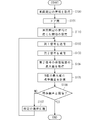
- FIG. 3 is a flowchart illustrating the operation of the communication device.
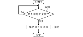
- FIG. 4 is a flowchart illustrating the operation of the mobile terminal.
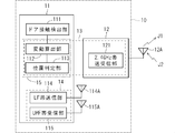
- FIG. 5 is a block diagram illustrating the configuration of the communication device.
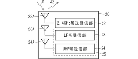
- FIG. 6 is a block diagram illustrating the configuration of the mobile terminal.
- the distance measuring device includes a first communication unit and a control unit.
- the first communication unit receives a signal that lasts for a predetermined period by a predetermined number of times.
- the control unit obtains a maximum value of the reception intensity of the signal received by the first communication unit within the predetermined period for each of the number of times, obtains a variation of the predetermined number of the maximum values, and the variation is a threshold value or more.
- the position of the transmission source that transmits the signal is separated from the first communication unit by a predetermined distance or more, and if the variation is less than the threshold value, the position is determined from the first communication unit. It is determined that the distance is shorter than the predetermined distance.
- control unit has a fluctuation calculation unit and a position determination unit.
- the fluctuation calculation unit obtains the maximum value of the reception intensity of the signal received by the first communication unit within the predetermined period for each of the number of times, and obtains the variation of the predetermined number of the maximum values. If the variation is greater than or equal to a threshold value, the position determination unit determines that the position of the transmission source that transmits the signal is separated from the first communication unit by a predetermined distance or more, and the variation is less than the threshold value. For example, it is determined that the position is closer than the predetermined distance from the first communication unit.
- distance measurement is performed without depending on the reception strength itself.
- the communication device of the present disclosure includes the distance measuring device of the present disclosure and a second communication unit.
- the second communication unit has a configuration for communicating with the transmission source.
- the second communication unit communicates with the transmission source on condition that the position is determined to be closer than the predetermined distance from the first communication unit.
- the communication device of the present disclosure contributes to power saving of the transmission source.
- the communication system of the present disclosure includes the communication device of the present disclosure and a second communication device.
- the second communication device has a third communication unit and a fourth communication unit.
- the third communication unit has a configuration for communicating with the first communication unit.
- the fourth communication unit has a configuration for communicating with the second communication unit.
- the second communication device functions as the transmission source.
- the first communication unit transmits a first signal to the third communication unit.
- the third communication unit transmits a second signal as the signal in response to receiving the first signal.
- the communication system of the present disclosure contributes to power saving of the transmission source.
- FIG. 1 is a conceptual diagram illustrating a communication system 100 according to the embodiment.
- the communication system 100 includes a communication device 10 and a mobile terminal 20.
- the mobile terminal 20 is configured to be able to communicate with the communication device 10.
- FIG. 1 shows a situation where the user 2 of the vehicle 1 leaves the vehicle 1.
- the fact that the communication device 10 is mounted on the vehicle 1 is indicated by a chain line connecting the two for convenience.
- the fact that the user 2 carries the mobile terminal 20 is indicated by a chain line connecting them for convenience.
- a signal J1 is transmitted from the communication device 10 to the mobile terminal 20, and the mobile terminal 20 transmits a signal J2 to the communication device 10.
- the signals J1 and J2 are transmitted using radio waves, for example, radio waves having a frequency in the 2.4 GHz band. In the following description, the signals J1 and J2 themselves are treated as radio waves.
- the signal J1 is, for example, an advertising signal adopted in Bluetooth Low Energy (Bluetooth is a registered trademark).
- the mobile terminal 20 transmits the signal J2 in response to the reception of the signal J1.
- FIG. 2 is a graph showing the relationship between the distance and the reception intensity in free space when a 2.402 GHz signal is transmitted with a transmission intensity of 8 dBm.
- the distance is a distance between a transmission source that emits a signal and a position where the signal is received.
- the reception strength is the reception strength at the position where the signal is received.
- the broken line shows the result of simulation.
- the solid line will be described later.
- the reception strength tends to decrease as the distance increases.
- the simulation result shows that due to the influence of fading, there is a distance in which the reception strength is significantly reduced although the distance is short. Such a distance is commonly called a null point.
- the fact that the communication device 10 receiving the signal J2 from the mobile terminal 20 measures the distance to the mobile terminal 20 only by the reception intensity means fading. It can be seen that it is not desirable in view of the influence of.
- FIG. 3 is a flowchart illustrating the operation of the communication device 10
- FIG. 4 is a flowchart illustrating the operation of the mobile terminal 20.
- Each of the flowcharts illustrates only the portion related to distance measurement, does not illustrate all the operations of the communication device 10, and does not illustrate all the operations of the mobile terminal 20.
- the information around the vehicle 1 is acquired in step S100.
- the information on the surroundings includes information on the surroundings where the vehicle 1 is located, such as an urban area or a countryside. Such information is easily acquired by a known car navigation device, for example.
- Step S101 is a process of detecting that the door of the vehicle 1 is closed. Specifically, for example, when the mobile terminal 20 is near the communication device 10, it detects that the door of the vehicle 1 is closed. It is not necessary to use the signals J1 and J2 to determine whether or not the mobile terminal 20 is in the vicinity of the communication device 10 when the door is closed, and a known method can be adopted. In other words, step S101 is executed using a known technique.
- the threshold value is set according to the above information in step S110.
- a smaller threshold value is set as compared with the case where the threshold value is determined according to FIG. 2, which shows the dependence of the reception intensity on the distance in free space. This is because the environment around the vehicle 1 may reduce the reception intensity, but it is unlikely to increase it.
- the threshold when the vehicle 1 is located in an environment with many people, the threshold is set to a value that is about 5 to 10 dBm smaller than the threshold determined in free space.
- the threshold value is set to a value that is about 30 dBm smaller than the threshold value determined in the free space.
- the threshold value is set to a value that is about 20 dBm smaller than the threshold value determined in free space.
- step S110 the first signal (signal J1) is transmitted from the communication device 10 to the mobile terminal 20 M times in step S102.
- step S201 it is determined in step S201 whether mobile terminal 20 has received the first signal.
- the determination result is affirmative, in other words, when it is determined that the mobile terminal 20 has received the first signal, the process proceeds to step S202, and the second signal (signal J2) is transmitted to the communication device 10.
- the mobile terminal 20 is a communication device that functions as a transmission source that transmits the second signal.
- step S104 the maximum value of the reception strength is obtained for each of the received second signals.
- Each of the second signals is a signal that lasts for a predetermined period, and the maximum value of the reception intensity for each of the second signals (hereinafter referred to as “period intensity maximum value”) is obtained in step S104.
- the second signal is received M times in step S103 and the second signal is received M times in step S104.
- Period intensity maxima may be obtained for each of the signals. However, if N maximum intensity values for period are sufficient for the processing described later, the maximum intensity value for period in step S104 may be acquired N times under the condition of N ⁇ M. In the following, it is assumed that N period intensity maximum values are acquired. In other words, the transmission of the first signal in step S102 is performed at least N times.
- Steps S103 and S104 may be processed in parallel.
- the maximum value of the period intensity of the (k ⁇ 1)-th second signal may be acquired in step S104 while the k-th second signal is received in step S103.
- step S104 standard deviations of N maximum period strength values are calculated in step S105. After step S105 is executed, it is determined in step S106 whether the standard deviation is greater than or equal to the threshold value.
- the standard deviation is greater than or equal to the threshold value, it is determined that the distance from the communication device 10 to the mobile terminal 20 is greater than or equal to a predetermined distance, and if the standard deviation is less than the threshold value, it is determined that the distance is less than the predetermined distance. .. That is, by comparing the standard deviation and the threshold value, the distance between the communication device 10 and the mobile terminal 20 is measured as the size of the predetermined distance.
- the solid line illustrates the maximum value of the period intensity.
- the effect of fading also appears in the maximum value of the period intensity, although it is not so remarkable as the simulation result.
- the maximum value of the period strength has less variation with respect to the distance than the reception strength when the distance is long.
- the variation of the reception intensity with respect to the distance can be considered as the variation of the maximum value of the period intensity at a certain distance by allowing the error of the distance.
- the reception intensity itself is used for distance measurement, the error in distance measurement may increase not only at the null point but also in the vicinity thereof.
- the distance can be measured without depending on the reception intensity itself.
- Adopting the standard deviation as the index indicating the variation is advantageous from the viewpoint of evaluating the variation using a well-known method.
- the standard deviation of the maximum value of the period strength when the distance from the communication device 10 to the mobile terminal 20 is 2 to 5 m is about 0.48 to 1.8
- the standard deviation of the maximum value of the period strength when it is 45 to 48 m. was about 5.42 to 19.40. Therefore, when the predetermined distance is assumed to be about 20 to 30 m, the threshold value of the standard deviation of the maximum value of the period intensity may be selected to be about 3.
- step S106 If it is determined in step S106 that the standard deviation is less than the threshold value, the process returns to step S102, and the distance measuring operation is continued. If it is determined that the standard deviation is greater than or equal to the threshold value, the distance measuring operation ends, and thereafter the first signal is not transmitted. Therefore, the mobile terminal 20 also does not transmit the second signal, and thus the power consumption of the mobile terminal 20 is reduced.
- step S107 a case where step S107 is provided in the middle of the flow of returning from step S106 to step S102 is illustrated.
- step S107 a predetermined communication process is performed.
- step S107 known communication such as authentication and vehicle control between the communication device 10 and the mobile terminal 20 is performed. In FIG. 1, such communication is indicated by signal J3.
- step S106 If it is determined in step S106 that the standard deviation is greater than or equal to the threshold, it is determined that the distance from the communication device 10 to the mobile terminal 20 is greater than or equal to the predetermined distance, and thus step S107 is not executed. Such non-execution of step S107 is also advantageous from the viewpoint of reducing the power consumption of the mobile terminal 20.
- FIG. 5 is a block diagram illustrating the configuration of the communication device 10.
- the communication device 10 is mounted on the vehicle 1.
- the communication device 10 includes a body control module 11 and a communication module 12.
- the communication module 12 has a first communication unit 121.
- the body control module 11 has a door contact detection unit 111, a fluctuation calculation unit 112, a position determination unit 113, an LF band transmission unit 114, and a UHF band reception unit 115.
- the door contact detection unit 111, the fluctuation calculation unit 112, the position determination unit 113, the LF band transmission unit 114, and the UHF band reception unit 115 operate in cooperation with each other using a known technique.
- the door contact detection unit 111 executes the process of step S101 shown by the flowchart of FIG.
- Information indicating that step S101 has been executed is transmitted from the door contact detection unit 111 to the communication module 12.
- the communication module 12 receives the information and operates the first communication unit 121.
- the first communication unit 121 executes the processing of steps S102 and S103.
- the first communication unit 121 transmits the first signal in the 2.4 GHz band via the antenna 12A, for example.
- the first communication unit 121 receives the second signal in the 2.4 GHz band via the antenna 12A, for example.
- the first communication unit 121 is additionally described as “2.4 GHz band transmission/reception unit”.
- the signals J1 and J2 may be adopted as the first signal and the second signal, respectively.
- the second signal is received by the first communication unit 121 at least N times. If the second signal is the signal J2, it can be considered that the first communication unit 121 receives the signal J2 in the 2.4 GHz band that lasts for a predetermined period by a predetermined number of times (N times).
- the fluctuation calculation unit 112 executes the process of step S105.
- the fluctuation calculation unit 112 obtains the maximum period intensity value of the signal J2 received by the first communication unit 121 for each number of times, and obtains the variation of the N maximum period intensity values by the standard deviation.
- step S104 may be executed by the first communication unit 121 or the fluctuation calculation unit 112.
- the position determination unit 113 executes the processing of steps S110 and S106.
- the position determination unit 113 determines whether the variation calculated as the standard deviation is equal to or more than the threshold value set in step S110. If the standard deviation is equal to or greater than the threshold value, it is determined that the position of the mobile terminal 20 is separated from the first communication unit 121 by a predetermined distance or more. In other words, the distance from the first communication unit 121 to the mobile terminal 20 (this may be seen as the distance from the communication device 10 to the mobile terminal 20 or the distance from the vehicle 1 to the user 2). Good) is determined to be equal to or greater than the predetermined distance. If the standard deviation is less than the threshold value, it is determined that the position of the mobile terminal 20 is closer than the predetermined distance from the first communication unit 121.
- step S106 The determination result of step S106, that is, the result of distance measurement is provided from the position determination unit 113 to the LF band transmission unit 114. If it is determined that the position of the mobile terminal 20 is closer than the predetermined distance from the first communication unit 121 (that is, the distance from the first communication unit 121 to the mobile terminal 20 is less than the predetermined distance), the LF band transmission unit 114 is determined. It becomes possible to operate. This operation corresponds to the process of step S107. That is, the communication indicated by the signal J3 in FIG. 1 can be executed by the LF band transmission unit 114.
- the LF band transmitter 114 handles signals using radio waves in the LF band (30 to 300 kHz).
- the first communication unit 121, the variation calculation unit 112, and the position determination unit 113 can be collectively understood as the distance measuring device 13 that measures the distance from the communication device 10 to the mobile terminal 20 with a predetermined distance as a threshold.
- the variation calculation unit 112 and the position determination unit 113 can be collectively understood as the control unit 15 that functions as the variation calculation unit 112 and the position determination unit 113.
- the control unit 15 includes a computer including a microprocessor (micro processor), ROM (Read Only Memory), RAM (Random Access Memory), and the like.
- microprocessor micro processor
- ROM Read Only Memory
- RAM Random Access Memory
- An arithmetic processing unit such as a microprocessor stores a computer program (computer program) including some or all of each step of a flowchart (flow chart) as shown in FIG. 3 in a ROM (Read Only Memory), a RAM (Random Access Memory). ) And the like are read from the storage unit and executed.
- the computer programs of these multiple devices can be installed from an external server device or the like.
- Such computer programs are in a state of being respectively stored in a recording medium such as a CD-ROM (Compact Disc Read Only Memory), a DVD-ROM (Digital Versatile Disk Only Memory), and a semiconductor memory (memory). Be distributed.
- a recording medium such as a CD-ROM (Compact Disc Read Only Memory), a DVD-ROM (Digital Versatile Disk Only Memory), and a semiconductor memory (memory).
- the LF band transmission unit 114 and the UHF band reception unit 115 can be collectively considered as the second communication unit 14 having a configuration for communicating with the mobile terminal 20.
- the second communication unit 14 communicates with the mobile terminal 20 on condition that the position of the mobile terminal 20 is determined to be closer than the predetermined distance from the first communication unit 121.
- the transmission by the LF band transmission unit 114 is performed via the antenna 114A, for example.
- Reception by the UHF band reception unit 115 is performed via the antenna 115A, for example.
- the communication device 10 includes the distance measuring device 13 and the second communication unit 14.
- FIG. 6 is a block diagram illustrating the configuration of the mobile terminal 20.
- the mobile terminal 20 includes a third communication unit 22, an LF band receiving unit 23, and a UHF band transmitting unit 24, which operate in cooperation with each other using a known technique.
- the third communication unit 22 has a configuration for communicating with the first communication unit 121.
- the third communication unit 22 executes steps S201 and S202. Specifically, the third communication unit 22 receives, for example, the first signal (signal J1) via the antenna 22A, and in response to receiving the first signal, for example, the second signal (via the antenna 22A). Signal J2).
- the LF band reception unit 23 handles signals using LF band radio waves
- the UHF band transmission unit 24 handles signals using UHF band radio waves (0.3 to 3 GHz).
- the communication indicated by the signal J3 in FIG. 1 can be executed by the LF band reception unit 23 and the UHF band transmission unit 24.
- the LF band receiving unit 23 and the UHF band transmitting unit 24 can be collectively understood as a fourth communication unit 25 having a configuration for communicating with the second communication unit 14.
- the LF band receiving unit 23 receives via the antenna 23A
- the UHF band transmitting unit 24 transmits via the antenna 24A.
- the mobile terminal 20 includes the third communication unit 22 and the fourth communication unit 25.
- ⁇ Modification ⁇ As an index for evaluating the variation of the signal J2, an unbiased standard deviation may be used instead of the standard deviation, a variance or an unbiased variance may be used, or another index may be adopted.
- the signal J2 may have the same contents as the signal J1 or may have different contents.
- the signals J1, J2 may employ multiple frequencies.
- the signal J1 may employ multiple frequencies and the signal J2 may employ one frequency. Examples of frequencies include 2.402 GHz, 2.426 GHz, and 2.480 GHz.
- the mobile terminal 20 may be realized by, for example, an electronic key commonly called FOB, or at least the third communication unit 22 may be realized by a smartphone.
- the communication device 10 may be realized by integrating the body control module 11 and the communication module 12 into a module.
Landscapes
- Engineering & Computer Science (AREA)
- Radar, Positioning & Navigation (AREA)
- Remote Sensing (AREA)
- Physics & Mathematics (AREA)
- General Physics & Mathematics (AREA)
- Mechanical Engineering (AREA)
- Computer Networks & Wireless Communication (AREA)
- Mobile Radio Communication Systems (AREA)
- Radar Systems Or Details Thereof (AREA)
Abstract
受信強度を利用しつつも、フェージングの影響を低減した測距が行われる。測距装置は、第1通信部と、制御部とを備える。第1通信部は、所定期間において持続する信号を、所定数の回数によって受信する。制御部は、第1通信部が受信した信号の受信強度の、所定期間内における最大値を受信した回数毎に求め、所定数の最大値のばらつきを求める。制御部は、ばらつきが閾値以上であれば、信号を発信する発信源の位置が第1通信部から所定距離以上で離れていると判定し、ばらつきが閾値未満であれば、発信源の位置が第1通信部から所定距離よりも近い、と判定する。
Description
本開示は、測距装置、通信装置、通信システムに関する。
リレーアタック(relay attack)と通称される車両窃盗の手法を防ぐため、通信機能を有する鍵(以下「電子キー(key)」と仮称)と車両とが離れている場合には、車両が開錠されない、あるいは車両が駆動されない技術が提案されている。
例えば電子キーがGPS(Global Positioning System)機能を備え、電子キーの位置情報を、車両に搭載された装置へ電子キーから送信する技術が提案されている(例えば下記の特許文献1)。
電子キーは、その携帯性から、駆動される電力が内蔵バッテリ(battery)に依存している。内蔵バッテリの電力消費が低減される観点においては、電子キーと車両とが離れているか否かを判断するためのGPS機能は避けられることが望ましい。
車両に搭載された通信装置が、電子キーから受信した電波の強度を用いて、車両と電子キーとの間の距離を評価することも可能である。しかしながら当該技術は受信強度それ自体から距離を評価するので、フェージング(fading)の影響を受けやすい。この影響は、実際には当該距離が小さいにも拘わらず受信強度が低下する現象を招来し、当該距離が大きいと誤認される可能性を高める。
そこで、本開示は、受信強度を利用しつつも、フェージングの影響を低減して測距を行う技術を提供することを目的とする。
本開示にかかる測距装置は、第1通信部と、制御部とを備える。前記第1通信部は、所定期間において持続する信号を所定数の回数によって受信する。前記制御部は、前記第1通信部が受信した前記信号の受信強度の前記所定期間内における最大値を前記回数毎に求め、前記所定数の前記最大値のばらつきを求め、前記ばらつきが閾値以上であれば前記信号を発信する発信源の位置が前記第1通信部から所定距離以上で離れていると判定し、前記ばらつきが前記閾値未満であれば、前記位置が前記第1通信部から前記所定距離よりも近い、と判定する。
本開示は、このような特徴的な処理部を備える測距装置として実現することができるのみならず、かかる特徴的な処理をステップ(step)とする測距方法として実現したり、かかるステップをコンピュータ(computer)に実行させるためのプログラム(program)として実現したりすることができる。また、測距装置の一部又は全部を実現する半導体集積回路として実現したり、測距装置を含む測距システム(system)として実現したりすることができる。
本開示にかかる測距装置によれば、受信強度を利用しつつも、フェージングの影響を低減して測距が行われる。
[本開示の実施形態の説明]
最初に本開示の実施態様が列記して説明される。
(1)本開示の測距装置は、第1通信部と、制御部とを備える。前記第1通信部は、所定期間において持続する信号を所定数の回数によって受信する。前記制御部は、前記第1通信部が受信した前記信号の受信強度の前記所定期間内における最大値を前記回数毎に求め、前記所定数の前記最大値のばらつきを求め、前記ばらつきが閾値以上であれば前記信号を発信する発信源の位置が前記第1通信部から所定距離以上で離れていると判定し、前記ばらつきが前記閾値未満であれば、前記位置が前記第1通信部から前記所定距離よりも近い、と判定する。
最初に本開示の実施態様が列記して説明される。
(1)本開示の測距装置は、第1通信部と、制御部とを備える。前記第1通信部は、所定期間において持続する信号を所定数の回数によって受信する。前記制御部は、前記第1通信部が受信した前記信号の受信強度の前記所定期間内における最大値を前記回数毎に求め、前記所定数の前記最大値のばらつきを求め、前記ばらつきが閾値以上であれば前記信号を発信する発信源の位置が前記第1通信部から所定距離以上で離れていると判定し、前記ばらつきが前記閾値未満であれば、前記位置が前記第1通信部から前記所定距離よりも近い、と判定する。
例えば前記制御部は変動算出部と位置判定部とを有する。前記変動算出部は、前記第1通信部が受信した前記信号の受信強度の前記所定期間内における最大値を前記回数毎に求め、前記所定数の前記最大値のばらつきを求める。前記位置判定部は、前記ばらつきが閾値以上であれば、前記信号を発信する発信源の位置が前記第1通信部から所定距離以上で離れていると判定し、前記ばらつきが前記閾値未満であれば、前記位置が前記第1通信部から前記所定距離よりも近い、と判定する。
本開示の測距装置によると、受信強度そのものに依存せずに測距される。
(2)前記ばらつきには前記所定数の前記最大値の標準偏差が採用されることが好ましい。
周知の手法でばらつきが評価されるからである。
本開示の通信装置は、本開示の測距装置と、第2通信部とを備える。前記第2通信部は、前記発信源との通信を行うための構成を有する。前記第2通信部は、前記位置が前記第1通信部から前記所定距離よりも近いと判定されたことを条件として、前記発信源と通信する。
本開示の通信装置は、発信源の省電力に資する。
本開示の通信システムは、本開示の通信装置と、第2通信装置とを備える。前記第2通信装置は、第3通信部と、第4通信部とを有する。前記第3通信部は、前記第1通信部との通信を行うための構成を有する。前記第4通信部は、前記第2通信部との通信を行うための構成を有する。前記第2通信装置は前記発信源として機能する。前記第1通信部は前記第3通信部に第1信号を送信する。前記第3通信部は前記第1信号を受信したことに応答して第2信号を前記信号として送信する。
本開示の通信システムは、発信源の省電力に資する。
[本開示の実施形態の詳細]
本開示の測距装置、通信装置、通信システムの具体例が、以下に図面を参照して説明される。なお、本開示はこれらの例示に限定されず、請求の範囲によって示され、請求の範囲と均等の意味および範囲内におけるすべての変更が含まれることが意図される。以下に記載される実施形態の少なくとも一部が任意に組み合わせられてもよい。
本開示の測距装置、通信装置、通信システムの具体例が、以下に図面を参照して説明される。なお、本開示はこれらの例示に限定されず、請求の範囲によって示され、請求の範囲と均等の意味および範囲内におけるすべての変更が含まれることが意図される。以下に記載される実施形態の少なくとも一部が任意に組み合わせられてもよい。
<全体構成>
図1は、実施形態に係る通信システム100を例示する概念図である。通信システム100は、通信装置10と携帯端末20とを備える。携帯端末20は通信装置10と通信可能に構成される。
図1は、実施形態に係る通信システム100を例示する概念図である。通信システム100は、通信装置10と携帯端末20とを備える。携帯端末20は通信装置10と通信可能に構成される。
図1においては車両1のユーザ2が車両1から離れる状況が示される。車両1に通信装置10が搭載されることは、便宜上、両者を繋ぐ鎖線によって示される。ユーザ2が携帯端末20を携帯することは、便宜上、両者を繋ぐ鎖線によって示される。
通信装置10から携帯端末20へ信号J1が送信され、携帯端末20は通信装置10へ信号J2を送信する。信号J1,J2は電波、例えば2.4GHz帯の周波数を有する電波を用いて送信される。以下の説明においては信号J1,J2それ自身が電波として扱われる。
信号J1,J2を通信する方法としては、例えばIEEE802.15.1の規格に則った通信方法が採用される。信号J1は例えばBluetooth Low Energy(Bluetoothは登録商標)で採用されるアドバタイジング(advertising)信号である。携帯端末20は信号J1の受信に応答して信号J2を送信する。
図2は、2.402GHzの信号が送信強度8dBmで送信されたときの、自由空間における距離と受信強度との関係を示すグラフである。当該距離は、信号を発信する発信源と当該信号を受信した位置との間の距離である。受信強度は、当該信号を受信した位置における受信強度である。
図2において破線はシミュレーション(simulation)結果を示す。実線については後述される。大まかな傾向として、距離が大きいほど受信強度が低下する傾向がある。シミュレーション結果は、フェージングの影響により、距離が近いにも拘わらず受信強度が顕著に低下する距離が存在することを示す。かかる距離はヌルポイント(null point)と通称される。
信号J2に即して図2を見れば、携帯端末20から信号J2を受信した通信装置10が、受信強度のみで携帯端末20までの距離を測定すること(つまり測距すること)は、フェージングの影響に鑑みて望ましくないことが分かる。
<動作>
図3は通信装置10の動作を例示するフローチャートであり、図4は携帯端末20の動作を例示するフローチャートである。いずれのフローチャートも測距に関する部分のみを例示しており、通信装置10の動作のすべてを例示するものでもなく、携帯端末20の動作のすべてを例示するものでもない。
図3は通信装置10の動作を例示するフローチャートであり、図4は携帯端末20の動作を例示するフローチャートである。いずれのフローチャートも測距に関する部分のみを例示しており、通信装置10の動作のすべてを例示するものでもなく、携帯端末20の動作のすべてを例示するものでもない。
図3において、ステップS100において車両1の周辺の情報が取得される。周辺の情報とは、例えば市街地であるとか、田園地帯であるとかの、車両1が位置する周囲の情報を含む。かかる情報は、例えば公知のカーナビゲーション(car navigation)装置で容易に取得される。
ステップS101は車両1のドア(door)が閉められたことを検知する処理である。具体的には例えば、携帯端末20が通信装置10の近傍にあるときに、車両1のドアが閉められたことを検知する。ドアが閉められる際に携帯端末20が通信装置10の近傍にあるか否かの判断は、信号J1,J2を用いる必要がなく、公知の手法が採用され得る。換言すればステップS101は公知の技術を用いて実行される。
ドアが閉められた後、ステップS110によって上記情報に応じた閾値の設定が行われる。自由空間における受信強度の距離に対する依存性を示す図2に即して閾値が決定される場合と比較して、より小さな閾値が設定される。車両1の周囲の環境が受信強度を低下させることはあっても、増大させることは考えられにくいからである。
例えば、人が多い環境に車両1が位置するときには、自由空間で決定される閾値に対して5~10dBm程度小さな値に閾値が設定される。駐車場など車両が多い環境に車両1が位置するときには、自由空間で決定される閾値に対して30dBm程度小さな値に閾値が設定される。建物の影響を考慮すべき環境に車両1が位置するときには、自由空間で決定される閾値に対して20dBm程度小さな値に閾値が設定される。
ステップS110が実行された後、ステップS102において、通信装置10から第1信号(信号J1)が携帯端末20へM回送信される。図4を参照して、携帯端末20は第1信号を受信したか否かがステップS201で判断される。当該判断結果が肯定的であったとき、換言すると携帯端末20は第1信号を受信したと判断されたとき、処理がステップS202に進み、第2信号(信号J2)が通信装置10へ送信される。携帯端末20は第2信号を発信する発信源として機能する通信装置である。
再び図3が参照され、ステップS103において、通信装置10は第2信号を受信する。ステップS104において、受信された第2信号の各々について、その受信強度の最大値が取得される。各々の第2信号は所定期間において持続する信号であり、各々の第2信号について、当該所定期間における受信強度の最大値(以下「期間強度最大値」と仮称)がステップS104において取得される。
第1信号はM回送信され、第2信号は第1信号を受信したことに応答して送信されるので、ステップS103では第2信号がM回受信され、ステップS104ではM回受信した第2信号の各々について期間強度最大値が取得され得る。ただし、後述する処理のためにN個の期間強度最大値で足りるのであれば、N≦Mを条件として、ステップS104における期間強度最大値の取得はN回でもよい。以下では、期間強度最大値はN個取得されるとして説明される。換言すれば、ステップS102における第1信号の送信は、少なくともN回行われる。
ステップS103,S104は並列して処理されてもよい。例えばk回目の第2信号がステップS103において受信されながら、(k-1)回目の第2信号の期間強度最大値がステップS104において取得されてもよい。
ステップS104が実行された後、ステップS105においてN個の期間強度最大値の標準偏差が計算される。ステップS105が実行された後、ステップS106において標準偏差が閾値以上であるか否かが判断される。
標準偏差が閾値以上であれば、通信装置10から携帯端末20までの距離が所定距離以上であると判定され、標準偏差が閾値未満であれば、当該距離が所定距離未満であると判定される。つまり標準偏差と閾値との比較により、所定距離に対する大小として、通信装置10と携帯端末20との間の測距が行われる。
図2において実線は期間強度最大値を例示する。期間強度最大値にも、シミュレーション結果ほど顕著ではないが、フェージングの影響が現れる。しかし期間強度最大値は、距離が遠いときの受信強度と比較して、距離に対するばらつきが小さい。距離に対する受信強度のばらつきは、距離の誤差を許すことにより、ある距離における期間強度最大値のばらつきとして考えられる。
フェージングの影響により、ヌルポイントおよびその近傍では受信強度が大きく低下する。よって受信強度そのものが利用されて測距されるとき、ヌルポイントのみならずその近傍では測距の誤差が高まる恐れがある。他方、期間強度最大値のばらつきが採用されることにより、受信強度そのものに依存せずに測距される。かかる測距はフェージングによる影響が低減される観点において有利である。ばらつきを示す指標として標準偏差が採用されることは、周知の手法を用いてばらつきが評価される観点において有利である。
例えば通信装置10から携帯端末20までの距離が2~5mのときの期間強度最大値の標準偏差は0.48~1.8程度であり、45~48mのときの期間強度最大値の標準偏差は5.42~19.40程度であった。よって所定距離として20~30m程度が想定される場合、期間強度最大値の標準偏差の閾値は3程度に選定されればよい。
ステップS106において標準偏差が閾値未満であると判断されれば処理がステップS102に戻り、測距動作が続行される。標準偏差が閾値以上であると判断されれば測距の動作は終了し、この後に第1信号は送信されない。よって携帯端末20も第2信号を送信せず、以て携帯端末20の消費電力が低減される。
図3においては、ステップS106からステップS102に戻るフローの途中にステップS107が設けられる場合が例示される。ステップS107においては、所定の通信処理が行われる。このステップS107においては例えば通信装置10と携帯端末20との間における認証、車両制御などの公知の通信が行われる。図1においてはこのような通信が信号J3で示される。
ステップS106において標準偏差が閾値以上であると判断されれば、通信装置10から携帯端末20までの距離が所定距離以上であると判定されるので、ステップS107は実行されない。このようなステップS107の不実行も、携帯端末20の消費電力が低減される観点で有利である。
<装置構成>
図5は通信装置10の構成を例示するブロック図である。通信装置10は車両1に搭載される。通信装置10はボディコントロールモジュール(body control module)11と、通信モジュール(module)12とを備える。通信モジュール12は第1通信部121を有する。ボディコントロールモジュール11はドア接触検出部111、変動算出部112、位置判定部113、LF帯送信部114、UHF帯受信部115を有する。ドア接触検出部111、変動算出部112、位置判定部113、LF帯送信部114、UHF帯受信部115は公知の技術を用いて相互に連携して動作する。
図5は通信装置10の構成を例示するブロック図である。通信装置10は車両1に搭載される。通信装置10はボディコントロールモジュール(body control module)11と、通信モジュール(module)12とを備える。通信モジュール12は第1通信部121を有する。ボディコントロールモジュール11はドア接触検出部111、変動算出部112、位置判定部113、LF帯送信部114、UHF帯受信部115を有する。ドア接触検出部111、変動算出部112、位置判定部113、LF帯送信部114、UHF帯受信部115は公知の技術を用いて相互に連携して動作する。
ドア接触検出部111は図3のフローチャートによって示されたステップS101の処理を実行する。ステップS101が実行されたことを示す情報は、ドア接触検出部111から通信モジュール12に伝達される。通信モジュール12は当該情報を受けて第1通信部121を動作させる。
第1通信部121はステップS102,S103の処理を実行する。ステップS102に即して言えば、第1通信部121は、例えばアンテナ12Aを介して2.4GHz帯の第1信号を送信する。第1通信部121は、例えばアンテナ12Aを介して2.4GHz帯の第2信号を受信する。この機能に鑑みて、図5では第1通信部121に「2.4GHz帯送受信部」と付記される。第1信号および第2信号として、それぞれ信号J1,J2が採用され得る。
ステップS103に即して言えば、第2信号が第1通信部121によって、少なくともN回受信される。第2信号が信号J2であれば、第1通信部121は、所定期間において持続する2.4GHz帯の信号J2を、所定数の回数(N回)によって受信する、と考えられ得る。
変動算出部112はステップS105の処理を実行する。変動算出部112は、第1通信部121が受信した信号J2の期間強度最大値を回数毎に求め、N個の期間強度最大値のばらつきを標準偏差によって求める。
ステップS104の処理は第1通信部121で実行されてもよいし、変動算出部112で実行されてもよい。
位置判定部113はステップS110,S106の処理を実行する。位置判定部113は、標準偏差として求められたばらつきがステップS110で設定された閾値以上であるか否かを判定する。標準偏差が閾値以上であれば、携帯端末20の位置が第1通信部121から所定距離以上で離れていると判定される。換言すれば、第1通信部121から携帯端末20までの距離(これは通信装置10から携帯端末20までの距離と見られてもよいし、車両1からユーザ2までの距離と見られてもよい)が所定距離以上であると判定される。標準偏差が閾値未満であれば、携帯端末20の位置は第1通信部121から所定距離よりも近い、と判定される。
ステップS106の判断結果、つまり測距の結果は、位置判定部113からLF帯送信部114に与えられる。携帯端末20の位置が第1通信部121から所定距離よりも近い(つまり第1通信部121から携帯端末20までの距離が所定距離未満である)と判定されれば、LF帯送信部114の動作が可能となる。かかる動作はステップS107の処理に対応する。つまり図1の信号J3によって示された通信は、LF帯送信部114で実行されることができる。LF帯送信部114はLF帯(30~300kHz)の電波を用いた信号を扱う。
第1通信部121と、変動算出部112と、位置判定部113とは纏めて、所定距離を閾値として通信装置10から携帯端末20までの距離を測定する測距装置13として理解され得る。
変動算出部112と位置判定部113とは纏めて、変動算出部112と位置判定部113との機能を果たす制御部15と理解され得る。
制御部15は、マイクロプロセッサ(micro processor)、ROM(Read Only Memory)、RAM(Random Access Memory)等を含み構成されるコンピュータを備える。
マイクロプロセッサ等の演算処理部は、図3に示すようなフローチャート(flow chart)の各ステップの一部または全部を含むコンピュータプログラム(computer program)を、ROM(Read Only Memory)、RAM(Random Access Memory)等の記憶部からそれぞれ読み出して実行する。
これら複数の装置のコンピュータプログラムは、それぞれ、外部のサーバ(server)装置等からインストール(install)されることができる。
また、このようなコンピュータプログラムは、それぞれ、CD-ROM(Compact Disc Read Only Memory)、DVD-ROM(Digital Versatile Disk Read Only Memory)、半導体メモリ(memory)等の記録媒体に格納された状態にあって流通する。
LF帯送信部114とUHF帯受信部115とを纏めて、携帯端末20と通信するための構成を有する第2通信部14として考えることができる。第2通信部14は、携帯端末20の位置が第1通信部121から所定距離よりも近いと判定されたことを条件として、携帯端末20と通信する。LF帯送信部114による送信は例えばアンテナ114Aを介して行われる。UHF帯受信部115による受信は例えばアンテナ115Aを介して行われる。
通信装置10は、測距装置13と第2通信部14とを備える、と理解され得る。
図6は携帯端末20の構成を例示するブロック図である。携帯端末20は第3通信部22と、LF帯受信部23と、UHF帯送信部24とを備え、これらは公知の技術を用いて相互に連携して動作する。第3通信部22は、第1通信部121との通信を行うための構成を有する。第3通信部22は、ステップS201,S202を実行する。具体的には第3通信部22は、例えばアンテナ22Aを介して第1信号(信号J1)を受信し、第1信号を受信したことに応答して、例えばアンテナ22Aを介して第2信号(信号J2)を送信する。
LF帯受信部23はLF帯の電波を用いた信号を、UHF帯送信部24はUHF帯の電波(0.3~3GHz)を用いた信号を、それぞれ扱う。図1の信号J3によって示された通信は、LF帯受信部23、UHF帯送信部24が実行できる。LF帯受信部23とUHF帯送信部24とは纏めて、第2通信部14と通信を行うための構成を有する第4通信部25と理解され得る。例えばLF帯受信部23はアンテナ23Aを介して受信し、UHF帯送信部24はアンテナ24Aを介して送信する。
携帯端末20は第3通信部22と第4通信部25とを備える、と理解され得る。
{変形例}
信号J2のばらつきを評価する指標として、標準偏差に代えて不偏標準偏差が用いられてもよいし、分散もしくは不偏分散が用いられてもよいし、その他の指標が採用されてもよい。
信号J2のばらつきを評価する指標として、標準偏差に代えて不偏標準偏差が用いられてもよいし、分散もしくは不偏分散が用いられてもよいし、その他の指標が採用されてもよい。
信号J2は信号J1と同じ内容であってもよいし、異なる内容であってもよい。信号J1,J2は複数の周波数を採用してもよい。信号J1が複数の周波数を採用し、信号J2が一つの周波数を採用してもよい。周波数の例として2.402GHz,2.426GHz,2.480GHzが挙げられる。
携帯端末20は例えばFOBと通称される電子キーで実現してもよいし、少なくとも第3通信部22がスマートフォン(smartphone)で実現されてもよい。通信装置10はボディコントロールモジュール11と通信モジュール12とが纏められてモジュール化されて実現されてもよい。
なお、上記実施形態および各変形例で説明した各構成は、相互に矛盾しない限り適宜組み合わせられ得る。
以上のようにこの発明は詳細に説明されたが、上記した説明は、すべての局面において、例示であって、この発明がそれに限定されるものではない。例示されていない無数の変形例が、この発明の範囲から外れることなく想定され得るものと解される。
1 車両
2 ユーザ
10 通信装置
11 ボディコントロールモジュール
12 通信モジュール
12A,22A,23A,24A アンテナ
13 測距装置
14 第2通信部
15 制御部
20 携帯端末
22 第3通信部
23 LF帯受信部
24 UHF帯送信部
25 第4通信部
100 通信システム
111 ドア接触検出部
112 変動算出部
113 位置判定部
114 LF帯送信部
114A,115A アンテナ
115 UHF帯受信部
121 第1通信部
J1,J2,J3 信号
S100~S107,S110,S201,S202 ステップ
2 ユーザ
10 通信装置
11 ボディコントロールモジュール
12 通信モジュール
12A,22A,23A,24A アンテナ
13 測距装置
14 第2通信部
15 制御部
20 携帯端末
22 第3通信部
23 LF帯受信部
24 UHF帯送信部
25 第4通信部
100 通信システム
111 ドア接触検出部
112 変動算出部
113 位置判定部
114 LF帯送信部
114A,115A アンテナ
115 UHF帯受信部
121 第1通信部
J1,J2,J3 信号
S100~S107,S110,S201,S202 ステップ
Claims (4)
- 第1通信部と、
制御部と
を備え、
前記第1通信部は、所定期間において持続する信号を所定数の回数によって受信し、
前記制御部は、前記第1通信部が受信した前記信号の受信強度の前記所定期間内における最大値を前記回数毎に求め、前記所定数の前記最大値のばらつきを求め、前記ばらつきが閾値以上であれば、前記信号を発信する発信源の位置が前記第1通信部から所定距離以上で離れていると判定し、前記ばらつきが前記閾値未満であれば、前記位置が前記第1通信部から前記所定距離よりも近い、と判定する、測距装置。 - 請求項1に記載の測距装置であって、
前記ばらつきには前記所定数の前記最大値の標準偏差が採用される、測距装置。 - 請求項1または請求項2に記載の測距装置と、
第2通信部と
を備え、
前記第2通信部は、前記発信源との通信を行うための構成を有し、前記位置が前記第1通信部から前記所定距離よりも近いと判定されたことを条件として、前記発信源と通信する、通信装置。 - 請求項3に記載の通信装置と、
第2通信装置と
を備え、
前記第2通信装置は、
第3通信部と、
第4通信部と
を有し、
前記第3通信部は、前記第1通信部との通信を行うための構成を有し、
前記第4通信部は、前記第2通信部との通信を行うための構成を有し、
前記第2通信装置は前記発信源として機能し、
前記第1通信部は前記第3通信部に第1信号を送信し、
前記第3通信部は前記第1信号を受信したことに応答して第2信号を前記信号として送信する、通信システム。
Applications Claiming Priority (2)
| Application Number | Priority Date | Filing Date | Title |
|---|---|---|---|
| JP2018-246429 | 2018-12-28 | ||
| JP2018246429A JP2020106441A (ja) | 2018-12-28 | 2018-12-28 | 測距装置、通信装置、通信システム |
Publications (1)
| Publication Number | Publication Date |
|---|---|
| WO2020137751A1 true WO2020137751A1 (ja) | 2020-07-02 |
Family
ID=71129779
Family Applications (1)
| Application Number | Title | Priority Date | Filing Date |
|---|---|---|---|
| PCT/JP2019/049648 Ceased WO2020137751A1 (ja) | 2018-12-28 | 2019-12-18 | 測距装置、通信装置、通信システム |
Country Status (2)
| Country | Link |
|---|---|
| JP (1) | JP2020106441A (ja) |
| WO (1) | WO2020137751A1 (ja) |
Cited By (1)
| Publication number | Priority date | Publication date | Assignee | Title |
|---|---|---|---|---|
| WO2022259364A1 (ja) * | 2021-06-08 | 2022-12-15 | パナソニックIpマネジメント株式会社 | 無線通信システム |
Citations (7)
| Publication number | Priority date | Publication date | Assignee | Title |
|---|---|---|---|---|
| JP2010162955A (ja) * | 2009-01-13 | 2010-07-29 | Tokai Rika Co Ltd | 電子キーシステムの車両出力電波調整装置 |
| WO2012124112A1 (ja) * | 2011-03-15 | 2012-09-20 | オムロン株式会社 | 無線通信監視装置、無線通信監視システム、無線通信監視方法、プログラムおよび記録媒体 |
| WO2014132873A1 (ja) * | 2013-02-27 | 2014-09-04 | 株式会社ニコン | 制御システム及び受信装置 |
| JP2016182854A (ja) * | 2015-03-25 | 2016-10-20 | 株式会社デンソー | ユーザ識別システム、車両用携帯機 |
| US20170285634A1 (en) * | 2016-03-30 | 2017-10-05 | Hyundai Motor Company | Vehicle and controlling method for the same |
| JP2018021422A (ja) * | 2016-08-05 | 2018-02-08 | 株式会社デンソー | 電子キーシステムおよび電子キー |
| JP2018195871A (ja) * | 2017-05-12 | 2018-12-06 | 三菱電機株式会社 | 携帯通信機および通信システム |
-
2018
- 2018-12-28 JP JP2018246429A patent/JP2020106441A/ja active Pending
-
2019
- 2019-12-18 WO PCT/JP2019/049648 patent/WO2020137751A1/ja not_active Ceased
Patent Citations (7)
| Publication number | Priority date | Publication date | Assignee | Title |
|---|---|---|---|---|
| JP2010162955A (ja) * | 2009-01-13 | 2010-07-29 | Tokai Rika Co Ltd | 電子キーシステムの車両出力電波調整装置 |
| WO2012124112A1 (ja) * | 2011-03-15 | 2012-09-20 | オムロン株式会社 | 無線通信監視装置、無線通信監視システム、無線通信監視方法、プログラムおよび記録媒体 |
| WO2014132873A1 (ja) * | 2013-02-27 | 2014-09-04 | 株式会社ニコン | 制御システム及び受信装置 |
| JP2016182854A (ja) * | 2015-03-25 | 2016-10-20 | 株式会社デンソー | ユーザ識別システム、車両用携帯機 |
| US20170285634A1 (en) * | 2016-03-30 | 2017-10-05 | Hyundai Motor Company | Vehicle and controlling method for the same |
| JP2018021422A (ja) * | 2016-08-05 | 2018-02-08 | 株式会社デンソー | 電子キーシステムおよび電子キー |
| JP2018195871A (ja) * | 2017-05-12 | 2018-12-06 | 三菱電機株式会社 | 携帯通信機および通信システム |
Non-Patent Citations (1)
| Title |
|---|
| TANAKA, SHINGO ET AL.: "Study on application of Bluetooth key-free system", IEICE TECHNICAL REPORT, vol. 103, no. 689, March 2004 (2004-03-01), pages 55 - 60 * |
Cited By (2)
| Publication number | Priority date | Publication date | Assignee | Title |
|---|---|---|---|---|
| WO2022259364A1 (ja) * | 2021-06-08 | 2022-12-15 | パナソニックIpマネジメント株式会社 | 無線通信システム |
| US12415478B2 (en) | 2021-06-08 | 2025-09-16 | Panasonic Automotive Systems Co., Ltd. | Wireless communication system |
Also Published As
| Publication number | Publication date |
|---|---|
| JP2020106441A (ja) | 2020-07-09 |
Similar Documents
| Publication | Publication Date | Title |
|---|---|---|
| US11427157B2 (en) | Low frequency or ultra wide band control by BLE in identification device | |
| CN114067461B (zh) | 车辆控制系统以及车辆控制方法 | |
| JP6313114B2 (ja) | 車両通信システム | |
| CN107422306B (zh) | 与定位设备和便携式设备相关联的、使用超高频波来定位便携式设备的方法 | |
| US20220292388A1 (en) | Machine learning mobile device localization | |
| WO2014103492A1 (ja) | 車両用キーレスシステム | |
| JP2017193884A (ja) | キーセキュリティ装置 | |
| KR102926390B1 (ko) | 차량 및 그 제어방법 | |
| US12481052B2 (en) | Localization with reduced power consumption | |
| JP4546717B2 (ja) | 車両の遠方からオートロックする方法 | |
| US20220408400A1 (en) | System and method for facilitating localizing an external object | |
| US11856497B2 (en) | Tracking and theft-recovery system for mobile assets | |
| CN112977336A (zh) | 车辆控制装置、车辆控制方法、记录介质和车辆控制系统 | |
| CN114829966A (zh) | 通信装置以及位置确定方法 | |
| US11546736B2 (en) | Vehicle control system, vehicle control method, and vehicle control server | |
| US20220030383A1 (en) | Vehicle control system and vehicle control method | |
| JP7697448B2 (ja) | 情報処理装置、車両、情報処理方法、及び情報処理プログラム | |
| WO2020090507A1 (ja) | 通信装置 | |
| CN108369756A (zh) | 被动进入系统的车辆钥匙及其方法 | |
| JP5526517B2 (ja) | 車載装置 | |
| US11307578B2 (en) | Manual drive changing notification apparatus and method of vehicle and vehicle including the same | |
| CN119486913A (zh) | 允许访问车辆的方法、装置、车辆和计算机程序 | |
| JP2020106441A (ja) | 測距装置、通信装置、通信システム | |
| WO2016063717A1 (ja) | キーレスエントリー装置 | |
| EP3435345A1 (en) | System and method for registering a position of loss of an object |
Legal Events
| Date | Code | Title | Description |
|---|---|---|---|
| 121 | Ep: the epo has been informed by wipo that ep was designated in this application |
Ref document number: 19902137 Country of ref document: EP Kind code of ref document: A1 |
|
| NENP | Non-entry into the national phase |
Ref country code: DE |
|
| 122 | Ep: pct application non-entry in european phase |
Ref document number: 19902137 Country of ref document: EP Kind code of ref document: A1 |