WO2020137502A1 - ごみ焼却炉及びその制御方法 - Google Patents
ごみ焼却炉及びその制御方法 Download PDFInfo
- Publication number
- WO2020137502A1 WO2020137502A1 PCT/JP2019/048184 JP2019048184W WO2020137502A1 WO 2020137502 A1 WO2020137502 A1 WO 2020137502A1 JP 2019048184 W JP2019048184 W JP 2019048184W WO 2020137502 A1 WO2020137502 A1 WO 2020137502A1
- Authority
- WO
- WIPO (PCT)
- Prior art keywords
- dust
- waste
- amount
- component
- accumulated
- Prior art date
- Legal status (The legal status is an assumption and is not a legal conclusion. Google has not performed a legal analysis and makes no representation as to the accuracy of the status listed.)
- Ceased
Links
Images



Classifications
-
- F—MECHANICAL ENGINEERING; LIGHTING; HEATING; WEAPONS; BLASTING
- F23—COMBUSTION APPARATUS; COMBUSTION PROCESSES
- F23G—CREMATION FURNACES; CONSUMING WASTE PRODUCTS BY COMBUSTION
- F23G5/00—Incineration of waste; Incinerator constructions; Details, accessories or control therefor
- F23G5/50—Control or safety arrangements
-
- F—MECHANICAL ENGINEERING; LIGHTING; HEATING; WEAPONS; BLASTING
- F23—COMBUSTION APPARATUS; COMBUSTION PROCESSES
- F23G—CREMATION FURNACES; CONSUMING WASTE PRODUCTS BY COMBUSTION
- F23G5/00—Incineration of waste; Incinerator constructions; Details, accessories or control therefor
- F23G5/02—Incineration of waste; Incinerator constructions; Details, accessories or control therefor with pretreatment
- F23G5/04—Incineration of waste; Incinerator constructions; Details, accessories or control therefor with pretreatment drying
-
- F—MECHANICAL ENGINEERING; LIGHTING; HEATING; WEAPONS; BLASTING
- F23—COMBUSTION APPARATUS; COMBUSTION PROCESSES
- F23G—CREMATION FURNACES; CONSUMING WASTE PRODUCTS BY COMBUSTION
- F23G5/00—Incineration of waste; Incinerator constructions; Details, accessories or control therefor
- F23G5/44—Details; Accessories
-
- F—MECHANICAL ENGINEERING; LIGHTING; HEATING; WEAPONS; BLASTING
- F23—COMBUSTION APPARATUS; COMBUSTION PROCESSES
- F23H—GRATES; CLEANING OR RAKING GRATES
- F23H7/00—Inclined or stepped grates
-
- Y—GENERAL TAGGING OF NEW TECHNOLOGICAL DEVELOPMENTS; GENERAL TAGGING OF CROSS-SECTIONAL TECHNOLOGIES SPANNING OVER SEVERAL SECTIONS OF THE IPC; TECHNICAL SUBJECTS COVERED BY FORMER USPC CROSS-REFERENCE ART COLLECTIONS [XRACs] AND DIGESTS
- Y02—TECHNOLOGIES OR APPLICATIONS FOR MITIGATION OR ADAPTATION AGAINST CLIMATE CHANGE
- Y02E—REDUCTION OF GREENHOUSE GAS [GHG] EMISSIONS, RELATED TO ENERGY GENERATION, TRANSMISSION OR DISTRIBUTION
- Y02E20/00—Combustion technologies with mitigation potential
- Y02E20/12—Heat utilisation in combustion or incineration of waste
Definitions
- the present invention relates to a refuse incinerator equipped with a stoker-type transfer device and a control method therefor, and more specifically to a technique for predicting the deadness of refuse.
- a waste incinerator equipped with a stoker-type transfer device that transfers waste from the upstream to the downstream in the order of a drying stage, a combustion stage, and a post-combustion stage.
- the waste incinerator is equipped with a dust supply device that supplies waste to the drying stage.
- the dust supply device includes a pusher that is reciprocally driven, and the amount of dust supplied to the drying stage changes depending on the stroke and operation cycle of the pusher.
- the waste transport speed of each stage of the drying stage, the combustion stage, and the post-combustion stage changes depending on the operating speed of the grate of each stage.
- Exhaust heat from the waste incinerator is recovered by the exhaust heat recovery boiler and used for power generation.
- Patent Document 1 the dust thickness in the drying stage and the combustion stage is detected by the infrared detecting means, and the dust transport speed in the drying stage and the dust transport speed in the combustion stage are independent based on the detected dust thickness. It is described that it adjusts.
- Patent Document 2 describes that the dust thickness of the drying stage is detected from the differential pressure between the pressure in the air box that sends the combustion air to the drying stage and the pressure in the furnace. The detected dust thickness of the drying stage is used for adjusting the dust conveying speed of the drying stage.
- Patent Document 3 describes that the dust thickness (dust height) of the dry stage is detected by oscillating a radio wave from above the dust of the dry stage and receiving the reflected wave. ..
- the detected dust thickness of the drying stage is used for adjusting the amount of dust supplied to the drying stage.
- JP-A-7-004629 Japanese Patent Publication No. 7-9288 JP, 2017-145980, A
- the quality of waste in the drying stage may fluctuate.
- the appropriate amount of waste accumulated in the furnace also changes. For example, even if the same volume of waste is carried into the combustion stage, the amount of waste that is burned may be insufficient if the density of waste is low, and the amount of waste that is burned may be excessive if the density of waste is high.
- the amount of exhaust heat generated by burning the waste decreases, and the amount of power generation decreases.
- the dust quality changes in this manner, maintaining the dust thickness in the drying stage at a predetermined value does not necessarily stabilize the power generation amount.
- the present invention has been made in view of the above circumstances, and an object thereof is to propose a technique for predicting the withdrawal of waste in a waste incinerator equipped with a stoker-type transfer device in consideration of fluctuations in waste quality. It is in.
- a method for controlling a refuse incinerator A method for controlling a refuse incinerator equipped with a stoker-type transport device for transporting waste in the order of a drying stage for drying the waste, a combustion stage for burning the dry waste, and a post-combustion stage for incineration of the burned waste.
- a combustion chamber having a stoker-type conveying device that conveys the waste in the order of a drying stage for drying the waste, a combustion stage for burning the dried waste, and a post-combustion stage for ashing the burned waste, A dust supply device for supplying waste to the drying stage, A dust amount detection device that detects the dust thickness or volume of the drying stage as the amount of accumulated dust in the furnace, From the time series data of the amount of accumulated waste, a fluctuation component from the standard value of the amount of accumulated waste in a predetermined evaluation period is extracted, and a decreasing component is extracted from the variable component, and monotonically decreases with respect to the amount of accumulated waste.
- a correction gain that is constant is calculated, and the reduction component is corrected by multiplying the reduction component by the correction gain, and the corrected reduction component is used as a dust reduction index, and a predetermined dust withdrawal is performed based on the dust reduction index.
- a control device that performs a corresponding process.
- the refuse reduction index is obtained by correcting the obtained reducing components with a correction gain corresponding to the amount of accumulated refuse in the furnace. Therefore, it is possible to evaluate the possibility of actually causing dust withdrawal based on the dust reduction index, and also to evaluate the degree of the lack of dust fuel (dust withdrawal) that occurs.
- FIG. 1 is a schematic diagram showing an example of a refuse incineration plant including a refuse incinerator according to an embodiment of the present invention.
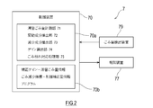
- FIG. 2 is a block diagram showing the configuration of the staying dust amount adjusting device.
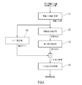
- FIG. 3 is a data flow diagram of the accumulated dust amount adjustment processing.
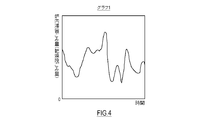
- FIG. 4 is a graph 1 showing an example of a time series change in the amount of accumulated refuse in the furnace during the evaluation period.
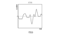
- FIG. 5 is a graph 2 showing the fluctuation component extracted from the time series data of the amount of accumulated refuse in the furnace of the graph 1.
- FIG. 6 is a graph 3 showing the decreasing component extracted from the fluctuation component of the graph 2.
- FIG. 7 is a diagram showing an example of the correction gain-retained dust amount information.
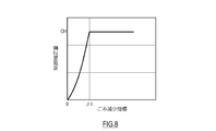
- FIG. 8 is a diagram showing an example of waste reduction index-control correction amount information.
- FIG. 1 is a schematic diagram showing an example of a refuse incineration plant 100 including a refuse incinerator 1 according to an embodiment of the present invention.
- the waste incineration plant 100 shown in FIG. 1 is recovered by a waste storage facility 3 that stores waste, a waste incinerator 1 that incinerates the waste, a boiler 2 that recovers exhaust heat of the waste incinerator 1, and a boiler 2. And a power generation facility 8 for generating power using the exhaust heat.
- the waste storage facility 3 and the power generation facility 8 may be provided adjacent to the incineration plant 100.
- the waste storage facility 3 is provided with a pit 60 adjacent to the waste incinerator 1 for temporarily storing the waste processed in the waste incinerator 1. Above the pit 60, a crane 6 is provided for loading the waste in the pit 60 into the refuse incinerator 1. The crane 6 grabs the waste in the pit 60 with a bucket and loads the waste into a loading hopper 12 of the waste incinerator 1 described later. Although the conveyor is interposed between the crane 6 and the input hopper 12 in FIG. 1, the conveyor may be omitted.
- the refuse incinerator 1 is a stoker type incinerator.
- the waste incinerator 1 is provided with a main combustion chamber 14 (primary combustion chamber) and a secondary combustion chamber 19.
- the floor portion of the main combustion chamber 14 is provided with a stoker-type transfer device S including a drying stoker 15, a combustion stoker 16, and a post-combustion stoker 17, which are arranged in a stepwise manner from the upper side to the lower side.
- the dry stoker 15 forms a drying stage S 1
- the combustion stoker 16 forms a combustion stage S 2
- the post-combustion stoker 17 forms a post-combustion stage S 3 .
- a discharge chute 18 that discharges incineration ash from the main combustion chamber 14 is provided on the downstream side of the post-combustion stoker 17.
- Stalker 15, 16 and 17 of each stage is driven by hydraulic cylinders 15c, 16c and 17c.
- hydraulic cylinders 15c, 16c and 17c By changing the reciprocating driving speed of the stokers 15, 16 and 17 by the hydraulic cylinders 15c, 16c and 17c, it is possible to independently change the conveying speed of the dust by the stokers 15, 16 and 17 of each stage.
- the air boxes 15a, 16a, 17a are provided below the stokers 15, 16, 17 of each stage.
- Primary combustion air 51 is supplied to the wind chambers 15a, 16a, 17a, and the primary combustion air 51 penetrates the stokers 15, 16, 17 from below and is introduced into the main combustion chamber 14.
- the flow rate of the primary combustion air supplied to each air box 15a, 16a, 17a is adjusted by the dampers 15b, 16b, 17b provided for each air box 15a, 16a, 17a.
- the secondary combustion air 52 is supplied from the ceiling of the main combustion chamber 14 toward the inside of the main combustion chamber 14.
- the input hopper 12 is connected to the inlet of the main combustion chamber 14 via a chute 13.
- the trash in the pit 60 is loaded into the loading hopper 12 by the crane 6.
- a dust-feeding device 41 that sends out the waste to the drying stage S 1 .
- the dust supply device 41 includes a pusher 41a that pushes out dust and a drive device 41b that horizontally reciprocates the pusher 41a.
- the waste that has been input from the input hopper 12 through the chute 13 to the inlet of the main combustion chamber 14 falls to the step 41c provided immediately upstream of the drying stage S 1 .
- the dust on the step 41c is pushed out to the drying stage S 1 by the dust supply device 41.
- the waste is dried in the drying stage S 1 , heated to near the ignition point, and sent to the combustion stage S 2 .
- the dried dust is ignited while being conveyed in the combustion stage S 2 , and a part of the ignited dust is thermally decomposed to generate a combustible pyrolysis gas.
- This pyrolysis gas rides on the primary combustion air 51, moves to the upper part of the main combustion chamber 14, and flame-combusts with the secondary combustion air 52.
- the rest of the ignited waste is burned in the post-combustion stage S 3 , and the incineration ash remaining after the combustion is discharged from the discharge chute 18 and sent to an ash processing facility (not shown).
- the combustion exhaust gas of the main combustion chamber 14 is mixed with the secondary combustion air 52 blown out from the ceiling portion on the downstream side of the main combustion chamber 14, and is completely combusted in the secondary combustion chamber 19.
- a boiler 2 for recovering thermal energy from the combustion exhaust gas flowing through the flue 20, 21, 22 is formed in the flue 20, 21, 22 that is continuous with the secondary combustion chamber 19 of the refuse incinerator 1.
- a water pipe 23 connected to a boiler drum 24 is stretched around the walls of the first flue 20 and the second flue 21. Further, the boiler drum 24 is connected to the superheat pipe 27 of the superheater 25.
- the superheat pipe 27 is installed in the third flue 22, and the steam passing through the superheat pipe 27 recovers the heat of the exhaust gas passing through the third flue 22.
- the amount of steam sent from the superheater 25 to the power generation equipment 8 is measured by the steam flow meter 39.
- the power generation facility 8 includes a power generator 85 and a steam turbine 84 that drives the power generator 85, and the steam turbine 84 is rotated by the steam sent from the boiler 2.
- the combustion exhaust gas that has passed through the boiler 2 is discharged to the exhaust passage 28 connected to the third flue 22.
- the exhaust path 28 is provided with a bag filter 81, an induction blower 82, and the like, and the exhaust gas of the boiler 2 is exhausted from the chimney 83 to the atmosphere after dust is separated by the bag filter 81.
- the operation of the refuse incineration plant 100 having the above configuration is controlled by the combustion control device 10.
- the combustion control device 10 uses the dust supply device 41 so that the main steam flow rate detected by the steam flow meter 39 has a predetermined value (and/or satisfies a predetermined waste incineration amount).
- so-called automatic combustion control is performed to adjust the flow rates of the primary combustion air 51 and the secondary combustion air 52 required to burn the dust.
- the incineration plant 100 includes the accumulated dust amount adjusting device 7 and increases the amount of dust corresponding to the predicted dust withdrawal, whereby the main steam flow rate of the boiler 2 due to the dust withdrawal. Of the electric power generation equipment 8 is suppressed, and the electric power generation amount of the electric power generation equipment 8 is stabilized.
- FIG. 2 is a block diagram showing the configuration of the accumulated waste amount adjusting device 7.
- the staying waste amount adjusting device 7 shown in FIG. 2 is a waste amount detecting device 79 (see FIG. 1) for detecting the amount of staying waste in the furnace, and prevents the deadness of dust from occurring based on the detected amount of staying waste in the furnace.
- a control device 70 (a retained dust amount control device) for controlling the amount of retained dust in the furnace.
- the accumulated dust amount adjusting device 7 is described independently of the combustion control device 10, but the accumulated dust amount adjusting device 7 may be configured as one functional unit of the combustion control device 10.
- the control device 70 includes functional units including a staying dust amount measuring unit 71, a fluctuation component extracting unit 72, a decreasing component extracting unit 73, a gain calculating unit 74, and a dust withdrawal processing unit 75.
- the control device 70 may be embodied as a kind of computer such as a PLC (programmable controller).
- the control device 70 includes a processor 70a including a CPU, MPU, GPU, and the like, and a volatile and nonvolatile memory 70b.
- the processor 70a reads and executes various programs stored in the memory 70b to perform processing for realizing each functional unit of the control device 70.
- Fig. 3 is a data flow diagram of the accumulated waste amount adjustment processing. The function of each functional unit of the control device 70 of the accumulated dust amount adjusting device 7 will be described with reference to FIGS. 2 and 3.
- the control device 70 is electrically connected to the dust amount detection device 79.
- the dust amount detection device 79 is provided in the dust incinerator 1 and periodically detects the dust amount in the drying stage S 1 .
- the amount of dust detected by the dust amount detector 79 is output to the controller 70 as the amount R of accumulated dust in the furnace.
- the accumulated dust amount measuring unit 71 stores the acquired accumulated dust amount R in the memory 70b in association with the detection time. In this way, the time series data of the amount R of accumulated dust in the furnace is accumulated in the memory 70b.
- the amount of dust detected by the dust amount detection device 79 may be the thickness of dust on the dry stoker 15 or the volume of dust on the dry stoker 15 that can be obtained from the thickness of dust.
- the form of the dust amount detection device 79 is not limited as long as it can detect the dust thickness on the dry stoker 15.
- the dust amount detection device 79 is configured by an infrared camera (or a visible light camera) and an image processing device, and the image processing device performs image processing on a captured image of the camera to obtain the dust thickness. Good.
- the dust amount detection device 79 includes an ultrasonic wave or radio wave transmission/reception device and a processing device, and the transmission/reception device oscillates a wave toward the surface of the dust on the drying stoker 15 and reflects it on the surface of the dust.
- the wave may be received, and the processing device may obtain the dust layer based on the time from oscillation to reception.
- the dust thickness may be a value detected at a single position on the drying stoker 15, or may be an average value of values detected at a plurality of positions on the drying stoker 15.
- the variable component extraction unit 72 extracts a short-term variable component of the accumulated waste amount R.
- the short-term fluctuation component of the accumulated dust amount R represents the fluctuation component of the accumulated dust amount in the furnace due to the intermittent dusting operation of the dust supply device 41.
- the fluctuation component extraction unit 72 filters the amount of accumulated dust R when extracting the fluctuation component.
- the filter used here may be, for example, a high-pass filter or a band-pass filter.
- the filter used is not particularly limited, but a filter with a large delay should be excluded for the purpose of detecting dust withdrawal in advance. Further, it is desirable that the cutoff frequency of the filter is longer than the time from the timing of dusting until the energy appears in the main steam flow rate of the boiler 2.
- the short-term fluctuation component of the accumulated waste amount R extracted by the filtering as described above is obtained by removing the long-term fluctuation component from the time series change of the accumulated waste amount R.
- the long-term fluctuation component removed by the filter can be regarded as the standard value of the amount R of accumulated dust. That is, it can be said that the short-term fluctuation component of the accumulated dust amount R is a fluctuation component from the standard value of the accumulated dust amount R. In this way, by performing the filtering for extracting the short-term fluctuation component from the accumulated waste amount R, the fluctuation component from the standard value of the accumulated waste amount R can be calculated without calculating the standard value (that is, the long-term fluctuation). Can be extracted.
- the fluctuation component from the standard value of the accumulated dust amount R may be a fluctuation component from the calculated standard value of the accumulated dust amount in the furnace (hereinafter, referred to as “standard value R S ”).
- the fluctuation component extraction unit 72 reads the time series data of the accumulated dust amount R in a predetermined evaluation period from the memory 70b, and extracts the fluctuation component from the standard value R S of the accumulated dust amount R.
- the standard value R S may be a median value, an average value, or a moving average value of the latest predetermined period in the time series data of the amount R of accumulated waste.
- the standard value R S may be a value input by the operator as appropriate and stored in the memory 70b.
- FIG. 4 is a graph 1 showing an example of the time series change of the amount R of accumulated dust in the furnace during the evaluation period
- the vertical axis represents the amount R of accumulated dust in the furnace
- the horizontal axis represents time
- FIG. 5 is a graph 2 showing the fluctuation component extracted from the time series data of the amount R of accumulated dust in the furnace of the graph 1.
- the vertical axis of the graph 2 represents the fluctuation component
- the horizontal axis represents the time.
- the horizontal axes (time) of graph 1 and graph 2 correspond to each other.
- the fluctuation component of the amount R of accumulated waste includes an increasing component larger than 0 and a decreasing component smaller than 0.
- the decreasing component extracting unit 73 extracts only the decreasing component from the fluctuation component.
- the decreasing component extracting unit 73 extracts the decreasing component by, for example, converting the plus component of the fluctuation component of the accumulated dust amount R into a minus component and converting the minus component into a plus component, and removing a number of 0 or less by the lower limit limiter. May be.
- the decreasing component extracted in this way becomes the absolute value of the decreasing component of the fluctuation component of the amount R of accumulated dust.
- FIG. 6 is a graph 3 showing the decreasing component extracted from the fluctuation component of the graph 2.
- the vertical axis of the graph 3 represents the decreasing component of the fluctuation component of the amount R of accumulated dust, and the horizontal axis represents the time.
- the horizontal axes (time) of graphs 1 to 3 correspond to each other.
- the gain calculation section 74 calculates a correction gain G corresponding to the amount R of accumulated dust. More specifically, the gain calculation unit 74 acquires the amount of staying dust R, and calculates the correction gain G from the amount of staying dust R by using “correction gain-retained dust amount information”.
- the correction gain-accumulation waste amount information is information indicating the relationship between the correction gain G and the accumulation waste amount R, and is stored in the memory 70b in advance.
- the amount of staying waste R used by the gain calculator 74 is the current amount of staying waste R detected by the waste amount detector 79.
- FIG. 7 shows an example of correction gain-accumulated waste amount information.
- the correction gain G is the maximum value GH in the range of the retained dust amount R from 0 to ⁇ 1
- the correction gain G is the maximum value in the range of the retained dust amount R from ⁇ 1 to ⁇ 2. It decreases from GH with an increase in the amount R of retained dust
- the correction gain G is the minimum value GL in the range where the amount R of retained dust is ⁇ 2 or more.
- the correction gain G monotonically decreases with respect to the accumulated dust amount R in the range of the accumulated dust amount R from ⁇ 1 to ⁇ 2.
- Both the maximum value GH and the minimum value GL are numbers larger than 0.
- the correction gain G is not limited to the above, and may be a constant value regardless of the value of the accumulated dust amount R.
- the dust withdrawal processing unit 75 multiplies the reduction component by the correction gain G to obtain the dust reduction index I.
- the dust thickness of the drying stage S 1 is sufficiently large, that is, when the value of the correction gain G is small, the possibility of dust withdrawal is low even if the decreasing component is large.
- the dust thickness of the drying stage S 1 is small, that is, when the value of the correction gain G is large, the possibility of dust withdrawal increases as the decreasing component increases.
- the dust reduction index I is an evaluation index of the possibility that dust withdrawal actually occurs when the reduction component is corrected by the correction gain G.
- the dust withdrawal processing unit 75 further performs a predetermined dust withdrawal process based on the dust reduction index I.
- the correction amount of the dust operation amount (or the dust amount) is calculated based on the dust reduction index I, and the dust operation amount corrected by the correction amount is used as the combustion control device. 10 (or the dust supply device 41).
- the correspondence processing unit 75 obtains the control correction amount C of the operating end corresponding to the dust reduction index I.
- the operation end may be, for example, at least one of the stroke of the pusher 41a of the dust feeding device 41 and the operation cycle of the pusher 41a.
- the dust withdrawal processing unit 75 uses the “dust reduction index-control correction amount information” stored in advance in the memory 70b when obtaining the control correction amount C of the operating end.
- the dust reduction index-control correction amount information is information indicating the relationship between the dust reduction index and the control correction amount of the operating end.
- FIG. 8 shows an example of waste reduction index-control correction amount information.
- the dust reduction index-control correction amount information shows that the control correction amount C gradually increases from 0 to the maximum correction amount CH in the range of the dust reduction index I from 0 to ⁇ 1, and the control correction amount when the dust reduction index I is ⁇ 1 or more.
- C is the maximum correction amount CH.
- Each of the control correction amounts C is a number larger than 0.
- the control correction amount C illustrated in FIG. 8 is a variable, the control correction amount C may be a constant. Further, when there are a plurality of operation ends, it is possible to give superiority or inferiority to the control correction amount C for each operation end by providing the dust reduction index-control correction amount information for each operation end.
- the calculated control correction amount C is output to the combustion control device 10.
- the combustion control device 10 corrects the control amount of the dust supply device 41 based on the acquired control correction amount C. That is, the control correction amount C corresponds to the correction amount of the dust supply amount by the dust supply device 41. As a result, when it is predicted that the dust will die, the amount of dust supplied to the drying stage S 1 increases, and the dust can be avoided.
- the waste incinerator 1 has the drying stage S 1 for drying the waste, the combustion stage S 2 for burning the dried waste, and the post-combustion stage for ashing the burned waste.
- a combustion chamber main combustion chamber 14 having a stoker type conveyance device S that conveys waste in the order of S 3, a dusting device 41 that supplies the waste to the drying stage S 1 , and a drying stage as the amount R of accumulated waste in the furnace.
- a dust amount detection device 79 for detecting the dust thickness or volume of S 1 and a control device 70 are provided.
- the control device 70 extracts, from the time series data of the amount of accumulated waste, a fluctuation component from the standard value of the amount R of accumulated waste in a predetermined evaluation period, and extracts a decreasing component of the fluctuation component, with respect to the amount R of accumulated waste. Then, a correction gain G that monotonically decreases or becomes constant is obtained, the reduction component is corrected by multiplying the reduction component by the correction gain G, and the corrected reduction component is set as the dust reduction index I, and based on the dust reduction index I. Perform a predetermined dust withdrawal process.
- control method of the refuse incinerator 1 is to detect the dust thickness or the dust volume of the drying stage S 1 as the accumulated dust amount R in the furnace, and from the time series data of the accumulated dust amount R, Extracting a variation component from the standard value of the amount of accumulated waste R in a predetermined evaluation period, extracting a decreasing component of the amount of variation, and obtaining a correction gain G that monotonically decreases or becomes constant with respect to the amount R of accumulated dust. That is, the reduction component is corrected by multiplying the reduction component by the correction gain G, and the corrected reduction component is set as the dust reduction index I, and a predetermined dust withdrawal process is performed based on the dust reduction index I. Including that.
- a decreasing component is calculated from the measured fluctuation amount of the accumulated waste amount R in the furnace, that is, the amount of waste in the drying stage S 1, and a decreasing component is calculated from the decreasing components. Capture signs of garbage withering.
- the decreasing component extracted from the measured value of the amount of accumulated waste R is used for the prediction of dust withdrawal, so even if the amount of accumulated accumulated waste in the furnace changes with the change in the quality of waste, it will have an effect on it. It is possible to predict a shortage of the waste fuel (waste dead) without receiving it, and it is possible to perform an appropriate process for the predicted waste dead.
- the waste reduction index I is obtained by correcting the calculated reduction component with the correction gain G corresponding to the amount R of accumulated dust in the furnace. Therefore, it is possible to evaluate the possibility of actually causing dust withdrawal by using the dust reduction index I, and also to evaluate the degree of lack of dust fuel (dust withdrawal) that occurs.
- the above-described refuse withdrawal process obtains the correction amount of the dust operation amount based on the dust reduction index I, and the dust operation amount corrected by the correction amount. Is output to the feeding device 41.
- the above-mentioned waste withdrawal processing is based on the waste reduction index I to obtain a correction amount of the amount of dust supplied to the drying stage S 1 . Including.
- the amount of dust supplied to the drying stage S 1 is automatically corrected based on the dust reduction index I, so that a good amount of accumulated dust in the furnace can be automatically maintained.
- the correction amount of the dust operation amount (correction amount of the dust amount) is based on the decrease component (that is, the dust decrease index I) corrected by the correction gain G corresponding to the amount R of accumulated dust in the furnace. ..
- the garbage withdrawal process is a correction of the dust supply amount (or the dust supply operation amount) to the drying stage S 1 .
- the processing for dealing with dust is not limited to this, and may include two or more kinds of processing.
- the above-mentioned dust withdrawal process predicts the presence or absence of dust withdrawal based on the dust reduction index I, and when dust withdrawal is predicted, outputs it to the informing device 77 to inform it. May be included.
- the staying dust amount adjusting device 7 may further include, for example, a notification device 77 (see FIG. 2) such as a sound or light notification device or a display monitor.
- the operator can adjust the amount of dust corresponding to the dust withdrawal, the transport speed of each stage of the stoker type transport device S, and the primary speed.
- the flow rate of the combustion air 51 can be adjusted, and the amount of dust introduced into the input hopper 12 can be adjusted.
- the garbage withdrawal treatment is performed based on the garbage reduction index I, but before that, the necessity of the garbage withdrawal treatment may be determined. ..
- the dust withdrawal processing unit 75 of the accumulated dust amount adjusting device 7 determines whether there is a sign of dust withdrawal (prediction of dust withdrawal) by comparing the dust reduction index I with a predetermined threshold, and the dust reduction index If I is equal to or less than the threshold value, it is assumed that dust dead is not predicted, and the dust dead handling process may be omitted.
- the dust withdrawal processing unit 75 may compare the dust reduction index I with a predetermined threshold value, or the integrated value of the dust reduction index I (graph in FIG. 6). The area of the thin black portion 3) may be compared with a predetermined threshold value.
- Waste incinerator 2 Boiler 3: Waste storage equipment 6: Crane 7: Accumulated waste amount adjusting device 70a: Processor 70b: Memory 8: Power generation equipment 10: Combustion control device 12: Input hopper 13: Chute 14: Main combustion chamber 15: Dry stoker 16: Combustion stoker 17: Post-combustion stokers 15a, 16a, 17a: Wind boxes 15b, 16b, 17b: Dampers 15c, 16c, 17c: Hydraulic cylinder 18: Discharge chute 20, 21, 22: Flue 24: Boiler drum 25: Superheater 28: Exhaust path 39: Steam flow meter 41: Dust supply device 51, 52: Combustion air 60: Pit 70: Control device 71: Accumulated dust amount measurement unit 72: Fluctuation component extraction unit 73: Decrease component Extraction unit 74: Gain calculation unit 75: Waste withdrawal processing unit 77: Notification device 79: Waste amount detection device 84: Steam turbine 85: Generator 100: Incineration plant
Landscapes
- Engineering & Computer Science (AREA)
- Mechanical Engineering (AREA)
- General Engineering & Computer Science (AREA)
- Incineration Of Waste (AREA)
- Chemical & Material Sciences (AREA)
- Combustion & Propulsion (AREA)
Abstract
ごみ枯れ予測方法は、炉内の滞留ごみ量として乾燥段のごみ厚さ又はごみ体積を検出すること、滞留ごみ量の時系列データから、所定の評価期間における滞留ごみ量の標準値からの変動成分を抽出すること、変動成分のうち減少成分を抽出すること、滞留ごみ量に対して単調減少又は一定となる補正ゲインを求めること、減少成分に補正ゲインを乗じることにより当該減少成分を補正すること、及び、補正された減少成分をごみ減少指標とし、当該ごみ減少指標に基づいて所定のごみ枯れ対応処理を行うこと、を含む。
Description
本発明は、ストーカ式搬送装置を備えたごみ焼却炉及びその制御方法に関し、より具体的には、ごみ枯れを予測する技術に関する。
従来から、ごみを乾燥段、燃焼段、後燃焼段の順に上流から下流へ向けて搬送するストーカ式搬送装置を備えたごみ焼却炉が知られている。ごみ焼却炉は、乾燥段へごみを供給する給じん装置を備える。給じん装置は、往復駆動されるプッシャを備え、プッシャのストロークや動作周期によって、乾燥段への給じん量が変化する。乾燥段、燃焼段、及び、後燃焼段の各段のごみ搬送速度は、各段の火格子の動作速度によって変化する。
ごみ焼却炉の排熱は、排熱回収ボイラで回収され、発電に利用される。安定した発電量を維持するために、乾燥段のごみ厚さを検出し、それに基づいてごみ焼却炉の乾燥段への給じん量やストーカによるごみ搬送速度を調整することが知られている。
特許文献1には、乾燥段及び燃焼段でのごみ厚さを赤外線検出手段で検出し、検出されたごみ厚さに基づいて、乾燥段のごみ搬送速度と燃焼段のごみ搬送速度とを独立して調整することが記載されている。
また、特許文献2には、乾燥段へ燃焼空気を送る風箱内の圧力と炉内圧力との差圧から、乾燥段のごみ厚さを検出することが記載されている。検出された乾燥段のごみ厚さは、乾燥段のごみ搬送速度の調整に利用される。
また、特許文献3には、乾燥段のごみに対し上方から電波を発振し、その反射波を受振することにより、乾燥段のごみ厚さ(ごみ高さ)を検出することが記載されている。検出された乾燥段のごみ厚さは、乾燥段への給じん量の調整に利用される。
上記のようなごみ焼却炉において、乾燥段のごみのごみ質が変動する場合がある。ごみ質の変化に伴って、適切な炉内滞留ごみ量も変化する。例えば、同じ体積のごみが燃焼段に搬入されても、ごみの密度が低いと燃焼するごみ量が不足し、ごみの密度が高いと燃焼するごみ量が過剰となることがある。燃焼するごみの著しい不足(以下、「ごみ枯れ」と称する)が生じると、ごみの燃焼により生じる排熱の回収量が低下し、発電量が低下する。このようにごみ質が変動する場合には、乾燥段のごみ厚さを所定の値に維持することは、必ずしも発電量を安定化させることにはならない。
本発明は以上の事情に鑑みてされたものであり、その目的は、ストーカ式搬送装置を備えたごみ焼却炉において、ごみ質の変動を考慮して、ごみ枯れを予測する技術を提案することにある。
本発明の一態様に係るごみ焼却炉の制御方法は、
ごみを乾燥させる乾燥段、乾燥したごみを燃焼させる燃焼段、及び、燃焼したごみを灰化させる後燃焼段の順にごみを搬送するストーカ式搬送装置を備えたごみ焼却炉の制御方法であって、
炉内の滞留ごみ量として前記乾燥段のごみ厚さ又はごみ体積を検出すること、
前記滞留ごみ量の時系列データから、所定の評価期間における前記滞留ごみ量の標準値からの変動成分を抽出すること、
前記変動成分のうち減少成分を抽出すること、
前記滞留ごみ量に対して単調減少又は一定となる補正ゲインを求めること、
前記減少成分に前記補正ゲインを乗じることにより当該減少成分を補正すること、及び、補正された前記減少成分をごみ減少指標とし、当該ごみ減少指標に基づいて所定のごみ枯れ対応処理を行うこと、を含むものである。
また、本発明の一態様に係るごみ焼却炉は、
ごみを乾燥させる乾燥段、乾燥したごみを燃焼させる燃焼段、及び、燃焼したごみを灰化させる後燃焼段の順にごみを搬送するストーカ式搬送装置を有する燃焼室と、
前記乾燥段へごみを供給する給じん装置と、
炉内の滞留ごみ量として前記乾燥段のごみ厚さ又は体積を検出するごみ量検出装置と、
前記滞留ごみ量の時系列データから、所定の評価期間における前記滞留ごみ量の標準値からの変動成分を抽出し、前記変動成分のうち減少成分を抽出し、前記滞留ごみ量に対して単調減少又は一定となる補正ゲインを求め、前記減少成分に前記補正ゲインを乗じることにより当該減少成分を補正し、補正された前記減少成分をごみ減少指標とし、当該ごみ減少指標に基づいて所定のごみ枯れ対応処理を行う制御装置とを、備えるものである。
上記ごみ焼却炉及びその制御方法では、計測された炉内の滞留ごみ量、即ち、乾燥段のごみ量から、滞留ごみ量の変動成分のうちの減少成分を求め、減少成分からごみ枯れの兆候を捉える。つまり、特許文献1~3のように、乾燥段のごみ厚さが所定量以上であるか否かに基づくのではなく、乾燥段のごみ厚さの減少変化に基づいて、ごみ枯れが生じる可能性を評価する。そのため、ごみ質の変化に伴って適切な炉内滞留ごみ量が変化しても、それに影響を受けることなくごみ枯れを予測することができ、予測されたごみ枯れに対して適切な処理を行うことができる。
更に、上記ごごみ焼却炉及びその制御方法において、ごみ減少指標は、求めた減少成分が炉内滞留ごみ量と対応する補正ゲインで補正されたものである。よって、ごみ減少指標に基づいて、実際にごみ枯れが発生する可能性を評価することができ、また、発生するごみ燃料の不足(ごみ枯れ)の程度を評価することができる。
本発明によれば、ストーカ式搬送装置を備えたごみ焼却炉において、ごみ質の変動を考慮して、ごみ枯れを予測する技術を提案することができる。
次に、図面を参照して本発明の実施形態を説明する。図1は、本発明の一実施形態に係るごみ焼却炉1を含むごみ焼却プラント100の一例を示す概略図である。
図1に示すごみ焼却プラント100は、ごみを貯蔵するごみ貯蔵設備3と、ごみを焼却するごみ焼却炉1と、ごみ焼却炉1の排熱を回収するボイラ2と、ボイラ2で回収された排熱を利用して発電を行う発電設備8とを備える。ごみ貯蔵設備3及び発電設備8は焼却プラント100に隣接して設けられてもよい。
〔ごみ貯蔵設備3〕
ごみ貯蔵設備3には、ごみ焼却炉1に隣設されて、ごみ焼却炉1で処理されるごみを一時的に貯蔵するピット60が設けられている。ピット60の上方には、ピット60内のごみをごみ焼却炉1へ投入するクレーン6が設けられている。クレーン6は、バケットでピット60内のごみを掴み、そのごみをごみ焼却炉1の後述する投入ホッパ12へ投入する。なお、図1ではクレーン6と投入ホッパ12との間にコンベヤが介在しているが、コンベヤは省略されてもよい。
ごみ貯蔵設備3には、ごみ焼却炉1に隣設されて、ごみ焼却炉1で処理されるごみを一時的に貯蔵するピット60が設けられている。ピット60の上方には、ピット60内のごみをごみ焼却炉1へ投入するクレーン6が設けられている。クレーン6は、バケットでピット60内のごみを掴み、そのごみをごみ焼却炉1の後述する投入ホッパ12へ投入する。なお、図1ではクレーン6と投入ホッパ12との間にコンベヤが介在しているが、コンベヤは省略されてもよい。
〔ごみ焼却炉1〕
ごみ焼却炉1は、ストーカ式焼却炉である。ごみ焼却炉1には、主燃焼室14(一次燃焼室)と、二次燃焼室19とが設けられている。主燃焼室14の床部には、上方から下方へ向けて階段状に配置された乾燥ストーカ15、燃焼ストーカ16、及び、後燃焼ストーカ17を備えるストーカ式搬送装置Sが設けられている。乾燥ストーカ15は乾燥段S1を形成し、燃焼ストーカ16は燃焼段S2を形成し、後燃焼ストーカ17は後燃焼段S3を形成する。後燃焼ストーカ17の下流側には、主燃焼室14から焼却灰を排出する排出シュート18が設けられている。
ごみ焼却炉1は、ストーカ式焼却炉である。ごみ焼却炉1には、主燃焼室14(一次燃焼室)と、二次燃焼室19とが設けられている。主燃焼室14の床部には、上方から下方へ向けて階段状に配置された乾燥ストーカ15、燃焼ストーカ16、及び、後燃焼ストーカ17を備えるストーカ式搬送装置Sが設けられている。乾燥ストーカ15は乾燥段S1を形成し、燃焼ストーカ16は燃焼段S2を形成し、後燃焼ストーカ17は後燃焼段S3を形成する。後燃焼ストーカ17の下流側には、主燃焼室14から焼却灰を排出する排出シュート18が設けられている。
各段のストーカ15,16,17は、油圧シリンダ15c,16c,17cで駆動される。油圧シリンダ15c,16c,17cによるストーカ15,16,17の往復駆動速度を変化させることで、各段のストーカ15,16,17によるごみの搬送速度を独立して変化させることができる。
各段のストーカ15,16,17の下方には風箱15a,16a,17aが設けられている。風箱15a,16a,17aには一次燃焼空気51が供給され、この一次燃焼空気51がストーカ15,16,17を下方から貫いて主燃焼室14内へ導入される。各風箱15a,16a,17aに供給される一次燃焼空気の流量は、各風箱15a,16a,17aに対して設けられたダンパ15b,16b,17bで調整される。また、主燃焼室14の天井から主燃焼室14内へ向けて二次燃焼空気52が供給される。
主燃焼室14の入口には、シュート13を介して投入ホッパ12が接続されている。投入ホッパ12へは、ピット60のごみがクレーン6によって投入される。また、主燃焼室14の入口には、ごみを乾燥段S1へ送り出す給じん装置41が設けられている。給じん装置41は、ごみを押し出すプッシャ41aと、プッシャ41aを水平方向に往復駆動する駆動装置41bとを備える。
上記構成のごみ焼却炉1では、投入ホッパ12からシュート13を通じて主燃焼室14の入口に投入されたごみが、乾燥段S1の直ぐ上流側に設けられたステップ41cに落下する。ステップ41c上のごみは、給じん装置41によって乾燥段S1へ押し出される。ごみは、乾燥段S1で乾燥されて着火点近傍まで加熱され、燃焼段S2へ送られる。乾燥したごみは、燃焼段S2で搬送されるうちに着火し、着火したごみの一部は熱分解して、可燃性の熱分解ガスを発生する。この熱分解ガスは、一次燃焼空気51に乗って主燃焼室14の上部へ移動して、二次燃焼空気52と共に炎燃焼する。着火したごみの残部は後燃焼段S3で燃焼し、燃焼後に残った焼却灰は排出シュート18から排出され、図示しない灰処理設備へ送られる。主燃焼室14の燃焼排ガスは、主燃焼室14の下流側の天井部分から吹き出す二次燃焼空気52と混合され、二次燃焼室19で完全燃焼する。
〔ボイラ2〕
ごみ焼却炉1の二次燃焼室19と連続された煙道20,21,22には、煙道20,21,22を流れる燃焼排ガスから熱エネルギーを回収するボイラ2が構成されている。第1煙道20及び第2煙道21の壁にはボイラドラム24と接続された水管23が張り巡らされている。また、ボイラドラム24は、過熱器25の過熱管27と接続されている。過熱管27は、第3煙道22内に設置され、過熱管27を通る蒸気は第3煙道22を通過する排ガスの熱を回収する。過熱器25から発電設備8へ送られる蒸気の量は蒸気流量計39により計測される。発電設備8は、発電機85及びそれを駆動する蒸気タービン84を含み、ボイラ2から送られた蒸気によって蒸気タービン84が回転する。
ごみ焼却炉1の二次燃焼室19と連続された煙道20,21,22には、煙道20,21,22を流れる燃焼排ガスから熱エネルギーを回収するボイラ2が構成されている。第1煙道20及び第2煙道21の壁にはボイラドラム24と接続された水管23が張り巡らされている。また、ボイラドラム24は、過熱器25の過熱管27と接続されている。過熱管27は、第3煙道22内に設置され、過熱管27を通る蒸気は第3煙道22を通過する排ガスの熱を回収する。過熱器25から発電設備8へ送られる蒸気の量は蒸気流量計39により計測される。発電設備8は、発電機85及びそれを駆動する蒸気タービン84を含み、ボイラ2から送られた蒸気によって蒸気タービン84が回転する。
ボイラ2を通過した燃焼排ガスは、第3煙道22と接続された排気路28へ排出される。排気路28には、バグフィルタ81や誘引式送風機82などが設けられており、ボイラ2の排ガスは、バグフィルタ81でダストが分離された後、煙突83から大気へ排出される。
上記構成のごみ焼却プラント100の運転は、燃焼制御装置10によって制御される。燃焼制御装置10は、蒸気流量計39で検出される主蒸気流量が所定の値となるように(及び/又は、所定のごみ焼却量を満足するように)、給じん装置41による給じん量や、ごみを燃焼するために必要な一次燃焼空気51及び二次燃焼空気52の流量を調整する、いわゆる、自動燃焼制御を行う。
〔滞留ごみ量調整装置7〕
上記のように焼却プラント100は自動燃焼制御されていても、ごみ質の変化やブリッジの発生などによって、燃焼段S2におけるごみの著しい不足(ごみ枯れ)が生じることがある。ごみ枯れが生じると、ごみの燃焼により発生するエネルギーが低減することから、ボイラ2の主蒸気流量が低減し、ひいては、発電設備8の発電量が不安定となる。そこで、本実施形態に係る焼却プラント100は、滞留ごみ量調整装置7を備え、予測されるごみ枯れに対応して給じん量を増加させることにより、ごみ枯れに起因するボイラ2の主蒸気流量の低減を抑制し、ひいては、発電設備8の発電量を安定化させる。
上記のように焼却プラント100は自動燃焼制御されていても、ごみ質の変化やブリッジの発生などによって、燃焼段S2におけるごみの著しい不足(ごみ枯れ)が生じることがある。ごみ枯れが生じると、ごみの燃焼により発生するエネルギーが低減することから、ボイラ2の主蒸気流量が低減し、ひいては、発電設備8の発電量が不安定となる。そこで、本実施形態に係る焼却プラント100は、滞留ごみ量調整装置7を備え、予測されるごみ枯れに対応して給じん量を増加させることにより、ごみ枯れに起因するボイラ2の主蒸気流量の低減を抑制し、ひいては、発電設備8の発電量を安定化させる。
図2は、滞留ごみ量調整装置7の構成を示すブロック図である。図2に示す滞留ごみ量調整装置7は、炉内滞留ごみ量を検出するごみ量検出装置79(図1、参照)と、検出された炉内滞留ごみ量に基づいてごみ枯れが生じないように炉内滞留ごみ量を制御する制御装置70(滞留ごみ量制御装置)とを備える。本実施形態において、滞留ごみ量調整装置7は、燃焼制御装置10から独立して記載されているが、滞留ごみ量調整装置7は燃焼制御装置10の一機能部として構成されていてもよい。
制御装置70は、滞留ごみ量計測部71と、変動成分抽出部72と、減少成分抽出部73と、ゲイン算出部74と、ごみ枯れ対応処理部75との各機能部を備える。制御装置70は、PLC(プログラマブルコントローラ)などの、一種のコンピュータとして具現化されてよい。制御装置70は、CPU、MPU、GPUなどで構成されたプロセッサ70aと、揮発性及び不揮発性のメモリ70bとを備える。プロセッサ70aは、メモリ70bに格納された各種プログラムを読み出して実行することで、制御装置70の各機能部を実現する処理を行う。
図3は、滞留ごみ量調整処理のデータフロー図である。図2及び図3を参照しつつ、滞留ごみ量調整装置7の制御装置70の各機能部の機能について説明する。
制御装置70は、ごみ量検出装置79と電気的に接続されている。ごみ量検出装置79は、ごみ焼却炉1に設けられて、乾燥段S1のごみ量を周期的に検出する。ごみ量検出装置79で検出されたごみ量は、炉内の滞留ごみ量Rとして制御装置70へ出力される。滞留ごみ量計測部71は、取得した滞留ごみ量Rを検出時刻と関連付けてメモリ70bへ記憶する。このようにして、メモリ70bには、炉内の滞留ごみ量Rの時系列データが蓄積されていく。
ごみ量検出装置79で検出されるごみ量は、乾燥ストーカ15上のごみ厚さ、或いは、ごみ厚さから求め得る乾燥ストーカ15上のごみの体積であってよい。ごみ量検出装置79は、乾燥ストーカ15上のごみ厚さを検出できるものであれば、その態様を問わない。例えば、ごみ量検出装置79は、赤外線カメラ(又は、可視光カメラ)及び画像処理装置で構成され、画像処理装置がカメラの撮像画像を画像処理することにより、ごみ厚さを求めるものであってよい。また、例えば、ごみ量検出装置79は、超音波又は電波の送受信装置及び処理装置で構成され、送受信装置で乾燥ストーカ15上のごみの表面に向けて波を発振するとともにごみの表面で反射した波を受振し、処理装置が発振から受振までの時間に基づいてごみ層さを求めるものであってよい。また、ごみ厚さは、乾燥ストーカ15上の単一位置において検出された値であってもよいし、乾燥ストーカ15上の複数位置において検出された値の平均値であってもよい。
変動成分抽出部72は、滞留ごみ量Rの短期的な変動成分を抽出する。滞留ごみ量Rの短期的な変動成分は、給じん装置41の断続的な給じん操作による炉内滞留ごみ量の変動成分を表す。ここで、変動成分抽出部72は、変動成分を抽出するに際し、滞留ごみ量Rのフィルタリングを行う。ここで使用されるフィルタは、例えば、ハイパスフィルタ、バンドパスフィルタなどであってよい。使用されるフィルタは特に限定されないが、ごみ枯れを事前に検知するという目的から、遅延の大きいフィルタは除かれるべきである。また、フィルタのカットオフ周波数は、給じんのタイミングから、そのエネルギーがボイラ2の主蒸気流量に表れるまでの時間より長いことが望ましい。上記のようにフィルタリングによって抽出された滞留ごみ量Rの短期的変動成分は、滞留ごみ量Rの時系列変化から長期的変動成分が除かれたものである。フィルタで除かれる長期的変動成分は、滞留ごみ量Rの標準値と見做すことができる。つまり、滞留ごみ量Rの短期的な変動成分は、滞留ごみ量Rの標準値からの変動成分ということができる。このように、滞留ごみ量Rに対し短期的変動成分を抽出するフィルタリングを行うことによって、標準値(即ち、長期的変動)を算出することなく、滞留ごみ量Rの標準値からの変動成分を抽出することができる。
但し、滞留ごみ量Rの標準値からの変動成分が、算出された炉内滞留ごみ量標準値(以下、「標準値RS」と表す)からの変動成分であってもよい。この場合、変動成分抽出部72は、滞留ごみ量Rの所定の評価期間の時系列データをメモリ70bから読み出して、滞留ごみ量Rの標準値RSからの変動成分を抽出する。標準値RSは、滞留ごみ量Rの時系列データのうち直近の所定期間の中央値、平均値、又は移動平均値であってよい。或いは、標準値RSは、オペレータにより適宜入力され、メモリ70bに記憶された値であってもよい。
図4は、評価期間の炉内滞留ごみ量Rの時系列変化の一例を表すグラフ1であり、縦軸は炉内滞留ごみ量Rを表し、横軸は時間を表す。図5は、グラフ1の炉内滞留ごみ量Rの時系列データから抽出された変動成分を表すグラフ2である。グラフ2の縦軸は変動成分を表し、横軸は時間を表す。グラフ1とグラフ2の横軸(時間)は対応している。
グラフ2に表されるように、滞留ごみ量Rの変動成分は、0より大きい増加成分と、0より小さい減少成分とを含む。減少成分抽出部73は、変動成分から、減少成分のみを抽出する。ここで、減少成分抽出部73は、例えば、滞留ごみ量Rの変動成分のプラスをマイナスに、マイナスをプラスにそれぞれ変換し、下限リミッタで0以下の数を除くことにより、減少成分を抽出してもよい。このようにして抽出された減少成分は、滞留ごみ量Rの変動成分のうち減少成分の絶対値となる。
図6は、グラフ2の変動成分から抽出された減少成分を表すグラフ3である。グラフ3の縦軸は滞留ごみ量Rの変動成分のうち減少成分を表し、横軸は時間を表す。グラフ1~3の横軸(時間)は対応している。
ゲイン算出部74は、滞留ごみ量Rに対応した補正ゲインGを算出する。より詳細には、ゲイン算出部74は、滞留ごみ量Rを取得し、この滞留ごみ量Rから「補正ゲイン-滞留ごみ量情報」を利用して補正ゲインGを算出する。補正ゲイン-滞留ごみ量情報は、補正ゲインGと滞留ごみ量Rとの関係を表す情報であり、予めメモリ70bに記憶されている。ゲイン算出部74が使用する滞留ごみ量Rは、ごみ量検出装置79で検出された現在の滞留ごみ量Rである。
図7には、補正ゲイン-滞留ごみ量情報の一例が示されている。この補正ゲイン-滞留ごみ量情報は、滞留ごみ量Rが0からα1までの範囲において補正ゲインGは最大値GHであり、滞留ごみ量Rがα1からα2までの範囲において補正ゲインGは最大値GHから滞留ごみ量Rの増加に伴って減少し、滞留ごみ量Rがα2以上の範囲において補正ゲインGは最小値GLである。滞留ごみ量Rがα1からα2までの範囲において補正ゲインGは、滞留ごみ量Rに対して単調に減少する。最大値GH及び最小値GLはいずれも0より大きい数である。但し、補正ゲインGは、上記に限定されず、滞留ごみ量Rの値に拘わらず一定の値であってもよい。
ごみ枯れ対応処理部75は、減少成分に補正ゲインGを乗じてごみ減少指標Iを求める。乾燥段S1のごみ厚さが十分に大きいときには、即ち、補正ゲインGの値が小さいときには、減少成分が大きくても、ごみ枯れが生じる可能性は低い。一方で、乾燥段S1のごみ厚さが小さいときには、即ち、補正ゲインGの値が大きいときには、減少成分の増加に伴って、ごみ枯れが生じる可能性が高まる。このように、ごみ減少指標Iは、減少成分が補正ゲインGで補正されることによって、実際にごみ枯れが生じる可能性の評価指標となっている。
ごみ枯れ対応処理部75は、更に、ごみ減少指標Iに基づいて、所定のごみ枯れ対応処理を行う。本実施形態において、ごみ枯れ対応処理は、ごみ減少指標Iに基づいて給じん操作量(又は、給じん量)の補正量を求め、当該補正量で補正された給じん操作量を燃焼制御装置10(又は、給じん装置41)へ出力することを含む。ここで、対応処理部75は、ごみ減少指標Iと対応した操作端の制御補正量Cを求める。操作端は、例えば、給じん装置41のプッシャ41aのストローク、プッシャ41aの動作周期のうち少なくとも1つであってよい。ごみ枯れ対応処理部75は、操作端の制御補正量Cを求めるに際し、予めメモリ70bに記憶された「ごみ減少指標-制御補正量情報」を利用する。ごみ減少指標-制御補正量情報は、ごみ減少指標と操作端の制御補正量との関係を表す情報である。
図8には、ごみ減少指標-制御補正量情報の一例が示されている。ごみ減少指標-制御補正量情報は、ごみ減少指標Iが0からβ1までの範囲において制御補正量Cは0から最大補正量CHまで徐々に増加し、ごみ減少指標Iがβ1以上において制御補正量Cは最大補正量CHとなる。制御補正量Cはいずれも0より大きい数である。なお、図8に例示された制御補正量Cは変数であるが、制御補正量Cは定数であってもよい。また、操作端が複数の場合には、ごみ減少指標-制御補正量情報を操作端ごとに設けることで、操作端ごとの制御補正量Cに優劣をつけることが可能となる。
求めた制御補正量Cは燃焼制御装置10へ出力される。燃焼制御装置10は、取得した制御補正量Cに基づいて給じん装置41の制御量を補正する。つまり、制御補正量Cは、給じん装置41による給じん量の補正量に相当する。これにより、ごみ枯れが予測される場合には、乾燥段S1への給じん量が増加し、ごみ枯れを回避することができる。
以上に説明したように、本実施形態に係るごみ焼却炉1は、ごみを乾燥させる乾燥段S1、乾燥したごみを燃焼させる燃焼段S2、及び、燃焼したごみを灰化させる後燃焼段S3の順にごみを搬送するストーカ式搬送装置Sを有する燃焼室(主燃焼室14)と、乾燥段S1へごみを供給する給じん装置41と、炉内の滞留ごみ量Rとして乾燥段S1のごみ厚さ又は体積を検出するごみ量検出装置79と、制御装置70とを備える。制御装置70は、滞留ごみ量の時系列データから、所定の評価期間における滞留ごみ量Rの標準値からの変動成分を抽出し、変動成分のうち減少成分を抽出し、滞留ごみ量Rに対して単調減少又は一定となる補正ゲインGを求め、減少成分に補正ゲインGを乗じることにより当該減少成分を補正し、補正された減少成分をごみ減少指標Iとし、当該ごみ減少指標Iに基づいて所定のごみ枯れ対応処理を行う。
また、本実施形態に係るごみ焼却炉1の制御方法は、炉内の滞留ごみ量Rとして乾燥段S1のごみ厚さ又はごみ体積を検出すること、滞留ごみ量Rの時系列データから、所定の評価期間における滞留ごみ量Rの標準値からの変動成分を抽出すること、変動成分のうち減少成分を抽出すること、滞留ごみ量Rに対して単調減少又は一定となる補正ゲインGを求めること、減少成分に補正ゲインGを乗じることにより当該減少成分を補正すること、及び、補正された減少成分をごみ減少指標Iとし、当該ごみ減少指標Iに基づいて所定のごみ枯れ対応処理を行うこと、を含む。
上記ごみ焼却炉1及びその制御方法では、計測された炉内の滞留ごみ量R、即ち、乾燥段S1のごみ量から、滞留ごみ量Rの変動成分のうち減少成分を求め、減少成分からごみ枯れの兆候を捉える。このように、滞留ごみ量Rの測定値から抽出された減少成分をごみ枯れの予測に利用するので、ごみ質の変化に伴って適切な炉内滞留ごみ量が変化しても、それに影響を受けることなくごみ燃料の不足(ごみ枯れ)を予測することができ、予測されたごみ枯れに対して適切な処理を行うことができる。
上記ごみ焼却炉1及びその制御方法において、ごみ減少指標Iは、求めた減少成分が炉内滞留ごみ量Rと対応する補正ゲインGで補正されたものである。よって、ごみ減少指標Iを利用して、実際にごみ枯れが発生する可能性を評価することができ、また、発生するごみ燃料の不足(ごみ枯れ)の程度を評価することができる。
また、本実施形態に係るごみ焼却炉1においては、上記のごみ枯れ対応処理が、ごみ減少指標Iに基づいて給じん操作量の補正量を求め、当該補正量で補正された給じん操作量を給じん装置41へ出力することを含む。同様に、本実施形態に係るごみ焼却炉1の制御方法においては、上記のごみ枯れ対応処理が、ごみ減少指標Iに基づいて、乾燥段S1への給じん量の補正量を求めることを含む。
このように、ごみ減少指標Iに基づいて乾燥段S1への給じん量が自動的に補正されるので、良好な炉内滞留ごみ量を自動的に維持することができる。また、給じん操作量の補正量(給じん量の補正量)は、炉内滞留ごみ量Rに対応する補正ゲインGで補正された減少成分(即ち、ごみ減少指標I)に基づくものである。これにより、炉内滞留ごみ量Rが十分に多いときには、給じん量の補正量が抑えられ、炉内滞留ごみ量Rが少ないときに、給じん量の補正量が大きくなる。このようにして、炉内滞留ごみ量Rを適切な値とすることができる。
以上に本発明の好適な実施の形態を説明したが、本発明の思想を逸脱しない範囲で、上記実施形態の具体的な構造及び/又は機能の詳細を変更したものも本発明に含まれ得る。上記のごみ焼却炉1及びその制御方法は、例えば、以下のように変更することができる。
上記実施形態に係るごみ焼却炉1及びその制御方法では、ごみ枯れ対応処理は、乾燥段S1への給じん量(又は給じん操作量)の補正である。但し、ごみ枯れ対応処理は、これに限定されず、また、2種以上の処理を含んでもよい。例えば、上記のごみ枯れ対応処理が、ごみ減少指標Iに基づいてごみ枯れの発生の有無を予測し、ごみ枯れが予測される場合には、それを報知するように報知装置77へ出力することを含んでもよい。この場合、滞留ごみ量調整装置7は、例えば、音声又は光による報知機、ディスプレイモニタなどの報知装置77(図2、参照)を更に備えてよい。
このように、ごみ枯れが予測される場合にそれが報知されることによって、オペレータは、ごみ枯れに対応して給じん量を調整したり、ストーカ式搬送装置Sの各段の搬送速度や一次燃焼空気51の流量を調整したり、投入ホッパ12へのごみ投入量を調整したりすることができる。
また、上記実施形態に係るごみ焼却炉1及びその制御方法では、ごみ減少指標Iに基づいてごみ枯れ対応処理が行われるが、その前に、ごみ枯れ対応処理の必要性が判断されてもよい。例えば、滞留ごみ量調整装置7のごみ枯れ対応処理部75は、ごみ減少指標Iと所定の閾値とを比較することによってごみ枯れの兆候の有無(ごみ枯れの予測)を判断し、ごみ減少指標Iが閾値以下であればごみ枯れが予測されないとして、ごみ枯れ対応処理を省略してもよい。また、ごみ枯れの兆候の有無を判断するに際し、ごみ枯れ対応処理部75は、ごみ減少指標Iと所定の閾値とを比較してもよいし、ごみ減少指標Iの積算値(図6のグラフ3の薄墨部分の面積)と所定の閾値とを比較してもよい。
1 :ごみ焼却炉
2 :ボイラ
3 :ごみ貯蔵設備
6 :クレーン
7 :滞留ごみ量調整装置
70a :プロセッサ
70b :メモリ
8 :発電設備
10 :燃焼制御装置
12 :投入ホッパ
13 :シュート
14 :主燃焼室
15 :乾燥ストーカ
16 :燃焼ストーカ
17 :後燃焼ストーカ
15a,16a,17a :風箱
15b,16b,17b :ダンパ
15c,16c,17c :油圧シリンダ
18 :排出シュート
20,21,22 :煙道
24 :ボイラドラム
25 :過熱器
28 :排気路
39 :蒸気流量計
41 :給じん装置
51,52 :燃焼空気
60 :ピット
70 :制御装置
71 :滞留ごみ量計測部
72 :変動成分抽出部
73 :減少成分抽出部
74 :ゲイン算出部
75 :ごみ枯れ対応処理部
77 :報知装置
79 :ごみ量検出装置
84 :蒸気タービン
85 :発電機
100 :焼却プラント
S :ストーカ式搬送装置
S1 :乾燥段
S2 :燃焼段
S3 :後燃焼段
Claims (6)
- ごみを乾燥させる乾燥段、乾燥したごみを燃焼させる燃焼段、及び、燃焼したごみを灰化させる後燃焼段の順にごみを搬送するストーカ式搬送装置を備えたごみ焼却炉の制御方法であって、
炉内の滞留ごみ量として前記乾燥段のごみ厚さ又はごみ体積を検出すること、
前記滞留ごみ量の時系列データから、所定の評価期間における前記滞留ごみ量の標準値からの変動成分を抽出すること、
前記変動成分のうち減少成分を抽出すること、
前記滞留ごみ量に対して単調減少又は一定となる補正ゲインを求めること、
前記減少成分に前記補正ゲインを乗じることにより当該減少成分を補正すること、及び、
補正された前記減少成分をごみ減少指標とし、当該ごみ減少指標に基づいて所定のごみ枯れ対応処理を行うこと、を含む、
ごみ焼却炉の制御方法。 - 前記ごみ枯れ対応処理が、前記ごみ減少指標に基づいて、前記乾燥段への給じん量の補正量を求めることを含む、
請求項1に記載のごみ焼却炉の制御方法。 - 前記ごみ枯れ対応処理が、前記ごみ減少指標に基づいてごみ枯れの発生の有無を予測し、ごみ枯れが予測される場合には、それを報知することを含む、
請求項1又は2に記載のごみ焼却炉の制御方法。 - ごみを乾燥させる乾燥段、乾燥したごみを燃焼させる燃焼段、及び、燃焼したごみを灰化させる後燃焼段の順にごみを搬送するストーカ式搬送装置を有する燃焼室と、
前記乾燥段へごみを供給する給じん装置と、
炉内の滞留ごみ量として前記乾燥段のごみ厚さ又は体積を検出するごみ量検出装置と、
前記滞留ごみ量の時系列データから、所定の評価期間における前記滞留ごみ量の標準値からの変動成分を抽出し、前記変動成分のうち減少成分を抽出し、前記滞留ごみ量に対して単調減少又は一定となる補正ゲインを求め、前記減少成分に前記補正ゲインを乗じることにより当該減少成分を補正し、補正された前記減少成分をごみ減少指標とし、当該ごみ減少指標に基づいて所定のごみ枯れ対応処理を行う制御装置とを、備える、
ごみ焼却炉。 - 前記ごみ枯れ対応処理が、前記ごみ減少指標に基づいて給じん操作量の補正量を求め、当該補正量で補正された給じん操作量を前記給じん装置へ出力することを含む、
請求項4に記載のごみ焼却炉。 - 報知装置を更に備え、
前記ごみ枯れ対応処理が、前記ごみ減少指標に基づいてごみ枯れの発生の有無を予測し、ごみ枯れが予測される場合には、それを報知するように前記報知装置へ出力することを含む、
請求項4又は5に記載のごみ焼却炉。
Priority Applications (3)
| Application Number | Priority Date | Filing Date | Title |
|---|---|---|---|
| KR1020217022005A KR102470121B1 (ko) | 2018-12-27 | 2019-12-10 | 쓰레기 소각로 및 그 제어 방법 |
| CN201980085712.9A CN113227654B (zh) | 2018-12-27 | 2019-12-10 | 垃圾焚烧炉及其控制方法 |
| PH12021551068A PH12021551068A1 (en) | 2018-12-27 | 2021-05-10 | Waste incinerator and method for controlling the same |
Applications Claiming Priority (2)
| Application Number | Priority Date | Filing Date | Title |
|---|---|---|---|
| JP2018245506A JP7231406B2 (ja) | 2018-12-27 | 2018-12-27 | ごみ焼却炉及びその制御方法 |
| JP2018-245506 | 2018-12-27 |
Publications (1)
| Publication Number | Publication Date |
|---|---|
| WO2020137502A1 true WO2020137502A1 (ja) | 2020-07-02 |
Family
ID=71128227
Family Applications (1)
| Application Number | Title | Priority Date | Filing Date |
|---|---|---|---|
| PCT/JP2019/048184 Ceased WO2020137502A1 (ja) | 2018-12-27 | 2019-12-10 | ごみ焼却炉及びその制御方法 |
Country Status (5)
| Country | Link |
|---|---|
| JP (1) | JP7231406B2 (ja) |
| KR (1) | KR102470121B1 (ja) |
| CN (1) | CN113227654B (ja) |
| PH (1) | PH12021551068A1 (ja) |
| WO (1) | WO2020137502A1 (ja) |
Families Citing this family (2)
| Publication number | Priority date | Publication date | Assignee | Title |
|---|---|---|---|---|
| JP7810617B2 (ja) * | 2022-08-03 | 2026-02-03 | 株式会社クボタ | ごみ焼却炉の燃焼状態推定方法、ごみ焼却炉の燃焼状態推定装置、ごみ焼却炉の搬送制御方法及びごみ焼却炉の搬送制御装置 |
| CN116447603B (zh) * | 2023-04-17 | 2025-09-30 | 中国能源建设集团西北电力试验研究院有限公司 | 一种垃圾焚烧给料方法、系统、终端及存储介质 |
Citations (7)
| Publication number | Priority date | Publication date | Assignee | Title |
|---|---|---|---|---|
| JPS5236874A (en) * | 1975-09-19 | 1977-03-22 | Hitachi Ltd | Control system and device for trash incinerator |
| JPH09170736A (ja) * | 1995-12-18 | 1997-06-30 | Nkk Corp | ごみ焼却炉のごみ定量供給方法 |
| JP2017116252A (ja) * | 2015-12-17 | 2017-06-29 | Jfeエンジニアリング株式会社 | 火格子式廃棄物焼却炉及び火格子式廃棄物焼却炉による廃棄物焼却方法 |
| JP2017187228A (ja) * | 2016-04-06 | 2017-10-12 | 日立造船株式会社 | ストーカ式焼却炉 |
| WO2018003223A1 (ja) * | 2016-06-28 | 2018-01-04 | 川崎重工業株式会社 | ごみ焼却設備及びごみ焼却設備の制御方法 |
| JP2018021686A (ja) * | 2016-08-01 | 2018-02-08 | 株式会社タクマ | ごみ移動速度検出機能を備えた燃焼制御装置 |
| CN108194934A (zh) * | 2016-12-31 | 2018-06-22 | 上海康恒环境股份有限公司 | 一种生活垃圾焚烧炉一次风独立布风流量联锁控制系统 |
Family Cites Families (9)
| Publication number | Priority date | Publication date | Assignee | Title |
|---|---|---|---|---|
| JP2788394B2 (ja) | 1993-06-18 | 1998-08-20 | 株式会社クボタ | ゴミ焼却炉 |
| JPH09273731A (ja) * | 1996-02-06 | 1997-10-21 | Nkk Corp | ごみ焼却炉の燃焼制御方法 |
| JPH10238735A (ja) * | 1996-12-27 | 1998-09-08 | Nkk Corp | ごみ焼却炉、ホッパブリッジ検出方法及びその装置 |
| JPH10311519A (ja) * | 1997-05-14 | 1998-11-24 | Nkk Corp | ごみ焼却炉のごみ投入用クレーンの制御方法および装置 |
| CN1320309C (zh) * | 2003-03-27 | 2007-06-06 | 株式会社田熊 | 填料器式垃圾焚烧炉的自动燃烧控制方法 |
| CN103234207B (zh) * | 2012-11-28 | 2015-04-15 | 上海康恒环境股份有限公司 | 一种生活垃圾焚烧炉自动燃烧垃圾料层厚度控制系统 |
| JP6468628B2 (ja) * | 2014-04-28 | 2019-02-13 | 株式会社タクマ | 燃焼制御方法および燃焼制御システム |
| JP6695161B2 (ja) * | 2016-02-15 | 2020-05-20 | 日立造船株式会社 | ストーカ式焼却炉 |
| JP6632490B2 (ja) * | 2016-04-28 | 2020-01-22 | 日立造船株式会社 | 計算装置、計算装置の制御方法、制御プログラム、および記録媒体 |
-
2018
- 2018-12-27 JP JP2018245506A patent/JP7231406B2/ja active Active
-
2019
- 2019-12-10 WO PCT/JP2019/048184 patent/WO2020137502A1/ja not_active Ceased
- 2019-12-10 KR KR1020217022005A patent/KR102470121B1/ko active Active
- 2019-12-10 CN CN201980085712.9A patent/CN113227654B/zh active Active
-
2021
- 2021-05-10 PH PH12021551068A patent/PH12021551068A1/en unknown
Patent Citations (7)
| Publication number | Priority date | Publication date | Assignee | Title |
|---|---|---|---|---|
| JPS5236874A (en) * | 1975-09-19 | 1977-03-22 | Hitachi Ltd | Control system and device for trash incinerator |
| JPH09170736A (ja) * | 1995-12-18 | 1997-06-30 | Nkk Corp | ごみ焼却炉のごみ定量供給方法 |
| JP2017116252A (ja) * | 2015-12-17 | 2017-06-29 | Jfeエンジニアリング株式会社 | 火格子式廃棄物焼却炉及び火格子式廃棄物焼却炉による廃棄物焼却方法 |
| JP2017187228A (ja) * | 2016-04-06 | 2017-10-12 | 日立造船株式会社 | ストーカ式焼却炉 |
| WO2018003223A1 (ja) * | 2016-06-28 | 2018-01-04 | 川崎重工業株式会社 | ごみ焼却設備及びごみ焼却設備の制御方法 |
| JP2018021686A (ja) * | 2016-08-01 | 2018-02-08 | 株式会社タクマ | ごみ移動速度検出機能を備えた燃焼制御装置 |
| CN108194934A (zh) * | 2016-12-31 | 2018-06-22 | 上海康恒环境股份有限公司 | 一种生活垃圾焚烧炉一次风独立布风流量联锁控制系统 |
Also Published As
| Publication number | Publication date |
|---|---|
| JP2020106216A (ja) | 2020-07-09 |
| CN113227654B (zh) | 2023-09-22 |
| PH12021551068A1 (en) | 2021-11-22 |
| CN113227654A (zh) | 2021-08-06 |
| KR102470121B1 (ko) | 2022-11-23 |
| KR20210102399A (ko) | 2021-08-19 |
| JP7231406B2 (ja) | 2023-03-01 |
Similar Documents
| Publication | Publication Date | Title |
|---|---|---|
| CN207019078U (zh) | 垃圾焚烧设备 | |
| JP6723864B2 (ja) | ごみ移動速度検出機能を備えた燃焼制御装置 | |
| JP6927127B2 (ja) | 廃棄物焼却方法 | |
| CN114729746B (zh) | 燃烧设备的控制装置、燃烧设备的控制方法及程序产品 | |
| JP7256016B2 (ja) | 予測モデル生成装置、予測モデル生成装置による予測モデル生成方法、及び予測装置 | |
| JP6779779B2 (ja) | ごみ焼却設備 | |
| KR102470121B1 (ko) | 쓰레기 소각로 및 그 제어 방법 | |
| JP2019178848A (ja) | 廃棄物焼却炉及び廃棄物焼却方法 | |
| KR102418074B1 (ko) | 배기가스 수은 제거 시스템 | |
| JP5767486B2 (ja) | 熱回収プラントおよびその運転制御方法 | |
| JP4036768B2 (ja) | 焼却炉の燃焼制御装置 | |
| CN113260817B (zh) | 垃圾供给速度推断装置和垃圾供给速度推断方法 | |
| JP6973246B2 (ja) | 廃棄物焼却方法 | |
| JP3669779B2 (ja) | ゴミ焼却炉の燃焼制御装置 | |
| JP3669778B2 (ja) | ゴミ焼却炉の燃焼制御装置 | |
| JPH10185157A (ja) | ゴミ質判定方法、装置、及び、ゴミ焼却炉の燃焼制御装置 | |
| JP2021050867A (ja) | 伝熱管のダスト除去装置 | |
| TW202202780A (zh) | 控制裝置、控制方法及記錄有程式之記錄媒體 | |
| JP3315036B2 (ja) | ゴミ焼却炉の燃焼制御装置 | |
| JP3356936B2 (ja) | 残存ゴミ量検出方法及び燃焼制御方法並びにゴミ焼却炉 | |
| JP2006125759A (ja) | 焼却炉の運転制御装置 | |
| JP3173963B2 (ja) | ゴミ焼却装置 | |
| JP2020094734A (ja) | 火格子式廃棄物焼却炉及び火格子式廃棄物焼却炉による廃棄物焼却方法 | |
| JPH06272844A (ja) | 焼却炉の燃焼状態検出装置 | |
| JP2002349827A (ja) | 焼却炉における給塵量制御方法 |
Legal Events
| Date | Code | Title | Description |
|---|---|---|---|
| 121 | Ep: the epo has been informed by wipo that ep was designated in this application |
Ref document number: 19904661 Country of ref document: EP Kind code of ref document: A1 |
|
| NENP | Non-entry into the national phase |
Ref country code: DE |
|
| ENP | Entry into the national phase |
Ref document number: 20217022005 Country of ref document: KR Kind code of ref document: A |
|
| 122 | Ep: pct application non-entry in european phase |
Ref document number: 19904661 Country of ref document: EP Kind code of ref document: A1 |