WO2020137397A1 - 塗工液塗工装置 - Google Patents
塗工液塗工装置 Download PDFInfo
- Publication number
- WO2020137397A1 WO2020137397A1 PCT/JP2019/047415 JP2019047415W WO2020137397A1 WO 2020137397 A1 WO2020137397 A1 WO 2020137397A1 JP 2019047415 W JP2019047415 W JP 2019047415W WO 2020137397 A1 WO2020137397 A1 WO 2020137397A1
- Authority
- WO
- WIPO (PCT)
- Prior art keywords
- coating
- masking tape
- coating liquid
- roller
- coating roller
- Prior art date
- Legal status (The legal status is an assumption and is not a legal conclusion. Google has not performed a legal analysis and makes no representation as to the accuracy of the status listed.)
- Ceased
Links
Images



Classifications
-
- B—PERFORMING OPERATIONS; TRANSPORTING
- B05—SPRAYING OR ATOMISING IN GENERAL; APPLYING FLUENT MATERIALS TO SURFACES, IN GENERAL
- B05C—APPARATUS FOR APPLYING FLUENT MATERIALS TO SURFACES, IN GENERAL
- B05C1/00—Apparatus in which liquid or other fluent material is applied to the surface of the work by contact with a member carrying the liquid or other fluent material, e.g. a porous member loaded with a liquid to be applied as a coating
- B05C1/04—Apparatus in which liquid or other fluent material is applied to the surface of the work by contact with a member carrying the liquid or other fluent material, e.g. a porous member loaded with a liquid to be applied as a coating for applying liquid or other fluent material to work of indefinite length
- B05C1/08—Apparatus in which liquid or other fluent material is applied to the surface of the work by contact with a member carrying the liquid or other fluent material, e.g. a porous member loaded with a liquid to be applied as a coating for applying liquid or other fluent material to work of indefinite length using a roller or other rotating member which contacts the work along a generating line
-
- B—PERFORMING OPERATIONS; TRANSPORTING
- B05—SPRAYING OR ATOMISING IN GENERAL; APPLYING FLUENT MATERIALS TO SURFACES, IN GENERAL
- B05C—APPARATUS FOR APPLYING FLUENT MATERIALS TO SURFACES, IN GENERAL
- B05C1/00—Apparatus in which liquid or other fluent material is applied to the surface of the work by contact with a member carrying the liquid or other fluent material, e.g. a porous member loaded with a liquid to be applied as a coating
- B05C1/04—Apparatus in which liquid or other fluent material is applied to the surface of the work by contact with a member carrying the liquid or other fluent material, e.g. a porous member loaded with a liquid to be applied as a coating for applying liquid or other fluent material to work of indefinite length
- B05C1/08—Apparatus in which liquid or other fluent material is applied to the surface of the work by contact with a member carrying the liquid or other fluent material, e.g. a porous member loaded with a liquid to be applied as a coating for applying liquid or other fluent material to work of indefinite length using a roller or other rotating member which contacts the work along a generating line
- B05C1/12—Apparatus in which liquid or other fluent material is applied to the surface of the work by contact with a member carrying the liquid or other fluent material, e.g. a porous member loaded with a liquid to be applied as a coating for applying liquid or other fluent material to work of indefinite length using a roller or other rotating member which contacts the work along a generating line the work being fed round the roller
-
- B—PERFORMING OPERATIONS; TRANSPORTING
- B05—SPRAYING OR ATOMISING IN GENERAL; APPLYING FLUENT MATERIALS TO SURFACES, IN GENERAL
- B05C—APPARATUS FOR APPLYING FLUENT MATERIALS TO SURFACES, IN GENERAL
- B05C1/00—Apparatus in which liquid or other fluent material is applied to the surface of the work by contact with a member carrying the liquid or other fluent material, e.g. a porous member loaded with a liquid to be applied as a coating
- B05C1/04—Apparatus in which liquid or other fluent material is applied to the surface of the work by contact with a member carrying the liquid or other fluent material, e.g. a porous member loaded with a liquid to be applied as a coating for applying liquid or other fluent material to work of indefinite length
- B05C1/16—Apparatus in which liquid or other fluent material is applied to the surface of the work by contact with a member carrying the liquid or other fluent material, e.g. a porous member loaded with a liquid to be applied as a coating for applying liquid or other fluent material to work of indefinite length only at particular parts of the work
-
- B—PERFORMING OPERATIONS; TRANSPORTING
- B05—SPRAYING OR ATOMISING IN GENERAL; APPLYING FLUENT MATERIALS TO SURFACES, IN GENERAL
- B05C—APPARATUS FOR APPLYING FLUENT MATERIALS TO SURFACES, IN GENERAL
- B05C11/00—Component parts, details or accessories not specifically provided for in groups B05C1/00 - B05C9/00
-
- B—PERFORMING OPERATIONS; TRANSPORTING
- B05—SPRAYING OR ATOMISING IN GENERAL; APPLYING FLUENT MATERIALS TO SURFACES, IN GENERAL
- B05C—APPARATUS FOR APPLYING FLUENT MATERIALS TO SURFACES, IN GENERAL
- B05C13/00—Means for manipulating or holding work, e.g. for separate articles
- B05C13/02—Means for manipulating or holding work, e.g. for separate articles for particular articles
Definitions
- the present invention relates to a coating liquid coating device for forming an uncoated region without a coating liquid at the widthwise end of an optical film when a coating liquid such as an adhesive is applied to an optical film.
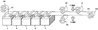
- Patent Document 1 An example of a manufacturing process for manufacturing a polarizing plate from a polarizer original fabric is described in Patent Document 1, for example.
- the polarizer original fabric GF delivered from the delivery roll OR is first cut off unusable portions (ears) on both widthwise end sides by a delivery cutter jig (not shown).
- the dichroic substance is washed by being immersed in, for example, a pure water bath in the swelling bath A in that order and swollen, and then immersed in a bath containing a dichroic substance such as iodine in the dyeing bath B to obtain the dichroic substance Are crosslinked by being immersed in a bath containing a cross-linking agent in the crosslinking bath C, and then stretched to have a desired total draw ratio in a state of being immersed in a bath containing boric acid in the stretching bath D.
- the washing bath E for example, by dipping in a washing bath, unnecessary residual substances such as boric acid adhered in the previous treatment are washed away, and then the protective film HF coated with the UV adhesive is laminated. After that, the UV adhesive is hardened by UV irradiation, and finally, the surface protective film SF is attached onto the protective film HF on the upper surface side to form the polarizing plate PO, which is wound up by the winding roll MR.
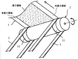
- Patent Document 2 As a means for solving such a problem, in Patent Document 2, as shown in FIG. 8, the width of the film 5 is masked by masking a portion of the coating roller 1 that contacts both ends of the coating roller 1 in the film width direction. It is described that uncoated areas are formed at both ends in the direction.
- Patent Document 2 in order to prevent the masking tape 3 from shifting in the width direction, a groove portion 11 is provided near both ends in the width direction of the coating roller 1, and the masking tape 3 is arranged in the groove portion 11 to perform masking. The deviation of the tape 3 is prevented.
- the width of the film 5 differs depending on the product, and when the film width is different, the position of the masking tape 3 also needs to be changed.
- the masking tape 3 since the masking tape 3 is arranged in the groove portion 11, the film width is different. There are problems that cannot be addressed.
- a coating liquid coating apparatus includes a coating roller that coats an optical film with a coating liquid, and the coating roller includes the outer peripheral surfaces of both end portions in the width direction of the coating roller.
- a coating liquid coating device arranged such that a masking tape is provided between the surfaces of both ends in the width direction of the optical film, wherein the masking tape is the both ends in the width direction of the coating roller. It is characterized in that it is wound around the coating roller with the coating liquid interposed therebetween.
- the masking tape is provided between the outer peripheral surfaces of both ends of the coating roller in the width direction and the surfaces of both ends of the optical film in the width direction, so that uncoated areas are surely provided at both ends of the optical film. Can be formed. Further, since the coating liquid is interposed between the masking tape and the coating roller, the position of the masking tape can be maintained due to the viscosity of the coating liquid. Therefore, it is possible to prevent the masking tape from shifting in the width direction with respect to the coating roller. Thus, the masking tape can be wound around the outer peripheral surface of the coating roller without shifting in the width direction of the masking tape without forming a groove portion having a constant position and size on the outer peripheral surface of the coating roller. Further, it is possible to deal with the case where the widths of the optical films are different.
- the rotation direction of the coating roller is opposite to the conveying direction of the optical film.
- the position of the masking tape can be maintained by the viscosity of the coating liquid, so that the masking with respect to the coating roller is performed. It is possible to prevent the tape from shifting in the width direction.
- a fixing portion for fixing one end portion located upstream of the masking tape in the longitudinal direction of the masking tape is fixed. It is preferably provided.
- the fixing part is provided only on one end of the masking tape, and the other end of the masking tape is free, so it is easy to install the masking tape.
- the masking tape is 10 cm from a portion where the coating roller and the optical film are in contact with each other toward a downstream side in a rotation direction of the coating roller. It is preferable that the roll is wound.
- the winding length of the masking tape from the portion where the coating roller and the optical film are in contact with each other is 10 cm or more, it is easier to maintain the position of the masking tape due to the viscosity of the coating liquid, and the masking tape for the coating roller can be maintained. It is easier to prevent the gap from moving in the width direction.
- the masking tape is 100 cm from the portion where the coating roller and the optical film are in contact with each other toward the downstream side in the rotation direction of the coating roller.
- the following winding is preferable.
- the length of the masking tape wound from the portion where the coating roller and the optical film are in contact with each other is 100 cm or less, it is possible to prevent the masking tape from being wound around the coating roller. Thereby, the stability of the coating liquid coating device can be secured.
- the masking tape is 20 cm from a portion where the coating roller and the optical film are in contact with each other toward a downstream side in a rotation direction of the coating roller. It is preferable that the roll is wound 50 cm or less.
- the winding length of the masking tape from the portion where the coating roller and the optical film are in contact with each other is 20 cm or more and 50 cm or less, it is possible to further prevent the masking tape from being displaced in the width direction with respect to the coating roller, and The stability of the liquid coating device can be further ensured.
- a fixing jig having a tension member that generates a tension force is provided, and the one end of the masking tape in the longitudinal direction or the masking tape. It is preferable that each of the both end portions in the longitudinal direction is fixed to the fixing portion via the fixing jig.
- the coating roller spins against the masking tape, but since the coating liquid is applied to the coating roller, the viscosity of the coating liquid increases the adhesion with the masking tape and increases the torque. In this way, at least one end of the masking tape is fixed to the fixing portion via the fixing jig, so that the fixing jig can absorb the torque of the coating roller.
- the fixing jig includes a grip member fixed to the fixing portion, the one end portion of the masking tape in the longitudinal direction, or the one end portion.
- the masking tape may further include a pair of plate members sandwiching both ends of the masking tape in the longitudinal direction, and the tension member may be disposed so as to connect the grip member and the pair of plate members. preferable.
- the fixing jig can be configured with a simple structure.
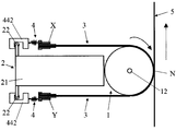
- the coating liquid coating apparatus of the present embodiment is for coating the protective film 5 (an example of an optical film) with a coating liquid such as a UV adhesive. As shown in FIGS. 1 and 2, it has a coating roller 1, a coating liquid supply means 2, and a fixing jig 4 for fixing a masking tape 3 described later to the coating liquid supply means 2.
- the masking tape 3 is a tape arranged on both ends of the coating roller 1 (for example, a gravure roller) in the width direction.
- the masking tape 3 includes an outer peripheral surface of a coating roller 1 for applying a coating liquid on the surface of a protective film 5 (a protective film is an example of an optical film) and a surface of a protective film 5 (an example of an optical film). It is a tape which is sandwiched between and to form an uncoated area on the surface of the protective film 5 (an example of an optical film) that is free of the coating liquid.
- the coating liquid coating device is, for example, a device provided with a coating roller 1 for coating the coating liquid on one surface of the protective film 5 (the surface to be attached to a polarizer (not shown)).
- a polarizing plate is obtained by bonding the protective film 5 to one surface or both surfaces of a polarizer (not shown) with a bonding roller (not shown).
- one coating roller 1 may be arranged.
- two coating rollers 1 are preferably arranged.
- the coating roller 1 is arranged between the feeding roller (not shown) of the protective film 5 and the bonding roller (not shown).
- the coating liquid is applied to one side or both sides of a polarizer (a polarizer is an example of an optical film) by the coating liquid coating device (coating roller 1) of the present invention, and a polarizer and a protective film 5 are formed. You may stick together.
- a polarizer is an example of an optical film
- a polyvinyl alcohol-based film may be uniaxially stretched by adsorbing a dichroic substance such as iodine or a dichroic dye.
- the thickness of the polarizer is preferably 5 ⁇ m to 80 ⁇ m.
- Any appropriate film is used as the protective film 5.
- Specific examples of the material that is the main component of such a film include cellulose resins such as triacetyl cellulose (TAC), (meth)acrylic resins, polyester resins, polyvinyl alcohol resins, polycarbonate resins, polyamide resins, and polyimide resins.
- Transparent resins such as polyether sulfone type, polysulfone type, polystyrene type, polynorbornene type, polyolefin type and acetate type.
- the coating roller 1 is formed in a cylindrical shape, and is configured to rotate with the cylindrical shaft 12 at the center position as the rotation axis.
- the coating roller 1 is formed so that its length in the width direction is slightly larger than that of the protective film 5.
- the coating roller 1 is arranged such that the outer peripheral surface thereof contacts the surface of the protective film 5 and rotates to coat the surface of the protective film 5 with the coating liquid supplied to the outer peripheral surface.
- the coating liquid supply means 2 has a main body portion 21 in which the coating liquid is stored, and a lateral rod 22 (fixed portion) provided in the main body portion 21.
- the coating liquid stored in the coating liquid supply means 2 may be, for example, an electron beam curable adhesive, a visible light curable adhesive, etc. in addition to the UV adhesive.
- a water-based adhesive can be suitably used.
- the width is preferably 10 to 100 mm.
- the masking tape 3 has line tapes T attached for strength improvement on both front and back surfaces of one end X in the longitudinal direction (see FIG. 6).
- the masking tape 3 is free because one end X in the longitudinal direction is fixed and the other end Y is not fixed. More specifically, the one end portion X of the masking tape 3 is fixed to the rod 22 (fixing portion) of the coating liquid supply means 2 via the fixing jig 4. The portion from the other end Y of the masking tape 3 to the vicinity of the middle portion M is wound around the outer peripheral surface of both ends in the width direction of the coating roller 1 along the circumferential direction with the coating liquid interposed therebetween. In No. 1, the masking tape is in a freely rotatable state. The masking tape 3 is provided between the outer peripheral surface of the widthwise end of the coating roller 1 and the surface of the widthwise end of the protective film 5 at a portion N where the coating roller 1 and the protective film 5 are in contact with each other. Are arranged as follows.
- the masking tape 3 is wound so as to stick to the outer peripheral surface of the coating roller 1 from the portion N where the coating roller 1 and the protective film 5 are in contact, toward the downstream side in the rotation direction of the coating roller 1.
- the winding length from the portion N of the masking tape 3 to the other end Y is preferably 10 cm or more from the viewpoint of reliably forming an uncoated area. From the viewpoint of preventing the other end Y from being caught in the coating roller 1, it is preferably 100 cm or less. Further, from the viewpoint of satisfying both of these viewpoints, it is more desirable that it is 20 cm or more and 50 cm or less.
- the coating roller 1 is arranged so as to rotate in the clockwise direction indicated by the arrow in FIG.
- the conveying direction of the protective film 5 (optical film) is shown by an arrow, and the rotation direction of the coating roller 1 is opposite to the conveying direction of the protective film 5.
- the masking tape 3 is arranged such that one end portion X is located upstream in the rotation direction of the coating roller 1 and the other end portion Y is located downstream in the rotation direction of the coating roller 1.
- the fixing jig 4 connects between the one end X of the masking tape 3 and the rod 22 of the coating liquid supply means 2, and the masking tape is directed toward the upstream side in the rotation direction of the coating roller 1 by a tension member 45 described later. A tension force for tightening 3 is generated.
- the fixing jig 4 is attachable to and detachable from the rod 22 as described later. Further, the fixing jig 4 is movable in the width direction after being removed from the rod 22. That is, the fixing jig 4 can be fixed to a predetermined position of the fixing portion, and after the fixing is released and moved to different positions in the width direction, the fixing jig 4 can be fixed again at the moving position.
- one end portion X of the masking tape 3 is fixed to the rod 22 of the coating liquid supply means 2 via the fixing jig 4, and the portion from the vicinity of the middle portion M to the other end portion Y is fixed.
- the portion is wound around the outer peripheral surface of both ends of the coating roller 1 in the width direction along the circumferential direction of the coating roller 1.
- the coating liquid from the coating liquid supply means 2 is supplied to almost the entire outer peripheral surface of the coating roller 1, the portion from the vicinity of the intermediate portion M of the masking tape 3 to the other end Y is liquid. It is held so as to be wound around the outer peripheral surfaces of both ends in the width direction of the coating roller 1 via the coating liquid.
- the coating roller 1 receives the coating liquid from the coating liquid supply means 2 while rotating in the clockwise direction.
- the protective film 5 is conveyed in a direction opposite to the rotation direction of the coating roller 1 (upward in FIG. 3) by a conveyance roller (not shown) while being in contact with the outer peripheral surface of the coating roller 1.
- the outer peripheral surface of the coating roller 1 between the two masking tapes 3, 3 makes the coating liquid on the outer peripheral surface contact the surface of the protective film 5 at the intermediate portion in the width direction at the contact portion with the protective film 5. Coating is performed to form a coating region on the surface of the intermediate portion in the width direction of the protective film 5.
- the outer peripheral surfaces of both ends in the width direction of the coating roller 1 cannot coat the coating liquid on the surfaces of the both ends in the width direction of the protective film 5 due to the presence of the masking tape 3, and thus the both end portions in the width direction of the protective film 5. An uncoated area is formed on the surface of.
- the position of the masking tape 3 can be changed by removing the fixing jig 4 from the rod 22, moving it together with the masking tape 3 in the width direction, and then fixing the fixing jig 4 to the rod 22 again.
- the position of the masking tape 3 can be easily changed, so that the coating liquid can be applied to films having different widths while forming uncoated regions at both widthwise ends.
- the second embodiment will be described below with reference to FIG.
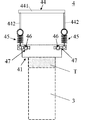
- the second embodiment is different from the first embodiment in that both longitudinal ends X and Y of the masking tape 3 are fixed to the rod 22 of the coating liquid supply means 2 via the fixing jigs 4, respectively.
- both longitudinal ends X and Y of the masking tape 3 are fixed to the rod 22 of the coating liquid supply means 2 via the fixing jigs 4, respectively.
- other configurations are the same, only different points will be described.
- the coating liquid supply means 2 is provided with a laterally-oriented first rod 22 (fixing portion) at an upper portion of a main body portion 21 and a laterally-oriented second rod 22 (fixing portion) at a lower portion of the main body portion 21. ) Is provided.
- One end portion X in the longitudinal direction of the masking tape 3 is fixed to the first rod 22 via the fixing jig 4 as in the first embodiment.
- the other end portion Y of the masking tape 3 in the longitudinal direction is fixed to the second rod 22 via another fixing jig 4 by the same structure as the one end portion X.
- the two rods 22 are configured to have the same configuration as the rod 22 of the first embodiment, and the two fixing jigs 4 are also the same as the fixing jig 4 of the first embodiment. Configured to have a configuration.
- the winding length of the masking tape 3 from the portion N where the coating roller 1 and the protective film 5 are in contact with each other to the downstream side in the rotation direction of the coating roller 1 is 10 cm or more and 100 cm or less, as in the first embodiment. It is desirable that the distance is 20 cm or more and 50 cm or less.
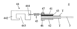
- 4 and 6 show the fixing jig 4 with the masking tape 3 held.
- the fixing jig 4 mainly has a pair of plate members 41 and 42, an elastic member 43, a grip member 44, and a pair of tension members 45.
- the plate member 41 is made of a rigid material such as stainless steel, for example, and has a substantially rectangular plate-shaped main body 411 and a pair of ear plates 412 protruding laterally from both ends in the width direction of the plate-shaped main body 411.
- a pair of connection holes 413 are formed in the plate-shaped body 411 near both ends in the width direction.
- a fixing hole 414 is formed in each of the pair of ear plates 412.
- the plate member 42 is made of, for example, a rigid material such as stainless steel, and is formed to have substantially the same outer shape as the plate-shaped main body 411 of the plate member 41.
- the plate member 42 has a pair of connection holes 423 formed in the vicinity of both ends in the width direction thereof at positions corresponding to the pair of connection holes 413.
- the elastic member 43 is a plate-shaped member made of an elastic material such as rubber, and has substantially the same outer shape as the plate-shaped main body 411 of the plate member 41.
- the elastic member 43 has a pair of connection holes 433 formed at positions corresponding to the pair of connection holes 413 near both ends in the width direction.
- the plate member 41, the elastic member 43, and the plate member 42 are arranged so as to overlap in order. That is, the pair of plate members 41 and 42 are assembled so as to sandwich the elastic member 43 therebetween. Further, one end portion X of the masking tape 3 is sandwiched between the plate member 42 and the elastic member 43 together with the line tapes T on both front and back surfaces, and the bolts 46 are inserted into the connection holes 413, 423, 433 and the nuts 47 are inserted. By connecting so as to be tightened, they are sandwiched and fixed by the fixing jig 4.
- the grip member 44 is made of a rigid material such as stainless steel, and is a portion of the fixing jig 4 that is fixed to the rod 22 of the coating liquid supply unit 2.
- the grip member 44 has a pair of hook plates 442 and a grip bar 441 connecting the pair of hook plates 442.
- the grip member 44 is attachable to and detachable from the rod 22, which is a fixed portion.
- the grip bar 441 is a bar shape (circular bar shape, square bar shape) that is long in the width direction of the masking tape 3, and is formed so that one ends of a pair of hook plates 442 are connected to each other, and an operator fixes the rod 22 to the rod 22. This is a part to be gripped when fixing the tool 4.
- Each of the pair of hook plates 442 is a plate-shaped member having a hook portion 443, and a fixing hole 444 is formed at the end opposite to the grip bar 441.
- the pair of hook plates 442 are fixed to both ends of the grip bar 441 in the width direction so as to face each other. Further, the hook portions 443 of the pair of hook plates 442 can be hooked on the rod 22.
- the tension member 45 described later pulls the hook plate 442 toward the coating roller 1, so that the hook plate 442 is fixed to the rod 22.
- the hook plate 442 fixed to the rod 22 can be removed from the rod 22 by pulling the hook plate 442 while pulling it to the side opposite to the coating roller 1.
- the attachment/detachment work of the fixing jig 4 with respect to the fixing portion can be easily performed by holding the grip bar 441.
- Each of the pair of tension members 45 is an elastic body (for example, a tension spring or the like) that generates a tension force when pulled, and is a tension coil spring in each of the above embodiments.
- One end of each of the pair of tension members 45 is fixed to the fixing hole 414 of the ear plate 412 of the plate member 41, and the other end thereof is arranged to be fixed to the fixing hole 444 of the grip member 44.
- the pair of tension members 45 are arranged so as to be line-symmetric with respect to the center line in the width direction of the masking tape 3.
- the bolt 46 and the nut 47 are for integrally fixing the plate member 41, the elastic member 43, the masking tape 3 and the plate member 42.
- a wing nut is used as the nut 47 from the viewpoint of improving operability.
- the coating roller 1 idles with respect to the masking tape 3, but since the coating liquid is applied to the coating roller 1, masking is performed by the viscosity of the coating liquid. The adhesiveness with the tape 3 is increased, and the torque is increased.
- the end portion in the longitudinal direction of the masking tape 3 is fixed to the rod 22 via the fixing jig 4, but the invention is not limited to this.
- the longitudinal end of the masking tape 3 may be directly fixed to the rod 22.
- the rod 22 as the fixing portion is formed in the main body portion 21 of the coating liquid supply means 2, but the present invention is not limited to this.
- the rod 22 may be formed as a fixed object different from the coating liquid supply means 2.
- the fixing part for fixing the end portion in the longitudinal direction of the masking tape is not limited to the rod, and other parts may be used as the fixing part.
- the coating liquid coating apparatus of the present invention can be applied to the polarizer GF and the surface protective film SF shown in FIG.
- the elastic member 43 is arranged in order to improve the friction between the plate member 42 and the masking tape 3, but the elastic member 43 may be omitted.
- a tension coil spring is used as the tension member 45, but the tension member 45 is not limited to this.
- a rubber thread or the like may be used.
- the line tape T is attached to both front and back surfaces of the one end X of the masking tape 3 in the longitudinal direction in order to prevent the masking tape 3 from breaking.
- the line tape T may be attached to only one of the front and back surfaces of the one end portion X. Further, the line tape T may not be attached.
Landscapes
- Coating Apparatus (AREA)
- Details Or Accessories Of Spraying Plant Or Apparatus (AREA)
Abstract
Description
(1)本発明の一態様に係る塗工液塗工装置は、光学フィルムに塗工液を塗工する塗工ローラを備え、前記塗工ローラは、その幅方向両端部の外周面と前記光学フィルムの幅方向両端部の表面との間にマスキングテープが介設されるように配置される塗工液塗工装置であって、前記マスキングテープは、前記塗工ローラの幅方向両端部との間に前記塗工液を介した状態で前記塗工ローラに巻かれることを特徴とする。
それによって、位置や寸法が一定の溝部を塗工ローラの外周面に形成しなくても、マスキングテープが幅方向にずれることなく、マスキングテープを塗工ローラの外周面に巻き付けることができる。さらに、光学フィルムの幅が異なる場合にも対応できる。
以下、図1及び図2を参照しながら第1実施態様を説明する。
[構成]
まず、本実施態様に係る塗工液塗工装置の構成について説明する。
固定治具4は、後述するように、ロッド22に着脱可能である。また、固定治具4は、前記ロッド22から外した後、幅方向に移動可能である。すなわち、固定治具4は、固定部の所定位置に固定でき、その固定を解除し且つ幅方向の異なる位置に移動させた後、その移動位置で再び固定できる。
続いて、本実施態様に係る塗工液塗工装置による塗工作業について説明する。
また、固定治具4をロッド22から外し、それをマスキングテープ3と共に幅方向に移動させた後、再び固定治具4をロッド22に固定することによって、マスキングテープ3の位置を変更できる。このように、マスキングテープ3の位置変更も簡単に行えるので、幅の異なるフィルムに対しても幅方向両端部に未塗工領域を形成しつつ塗工液を塗工できる。
本実施形態によって、マスキングテープ3の幅方向へのずれを防止でき、且つ光学フィルムの幅が異なる場合にも対応できる塗工液塗工装置を提供することが可能となる。
以下、図3を参照しながら第2実施態様を説明する。
第2実施態様は、第1実施態様と比べてマスキングテープ3の長手方向の両端部X、Yがそれぞれ固定治具4を介して塗工液供給手段2のロッド22に固定される点が相違し、他の構成は同じであるので、異なる点についてのみ説明する。
<固定治具>
グリップ部材44は、固定部であるロッド22に着脱可能である。
<変形形態>
Claims (9)
- 光学フィルムに塗工液を塗工する塗工ローラを備え、
前記塗工ローラは、その幅方向両端部の外周面と前記光学フィルムの幅方向両端部の表面との間にマスキングテープが介設されるように配置される塗工液塗工装置であって、
前記マスキングテープは、前記塗工ローラの幅方向両端部との間に前記塗工液を介した状態で前記塗工ローラに巻かれる、ことを特徴とする塗工液塗工装置。 - 前記塗工ローラの回転方向は前記光学フィルムの搬送方向とは逆方向である、ことを特徴とする請求項1に記載の塗工液塗工装置。
- 前記マスキングテープの長手方向両端部のうち、前記塗工ローラの回転方向において上流側に位置する一端部を固定する、固定部が設けられる、ことを特徴とする請求項1または2に記載の塗工液塗工装置。
- 前記マスキングテープの長手方向両端部のそれぞれを固定する固定部が設けられる、ことを特徴とする請求項1または2に記載の塗工液塗工装置。
- 前記マスキングテープは、前記塗工ローラと前記光学フィルムが接する部分から、前記塗工ローラの回転方向の下流側に向けて10cm以上巻かれる、ことを特徴とする請求項1乃至4のいずれか一項に記載の塗工液塗工装置。
- 前記マスキングテープは、前記塗工ローラと前記光学フィルムが接する部分から、前記塗工ローラの回転方向の下流側に向けて100cm以下巻かれる、ことを特徴とする請求項1乃至5のいずれか一項に記載の塗工液塗工装置。
- 前記マスキングテープは、前記塗工ローラと前記光学フィルムが接する部分から、前記塗工ローラの回転方向の下流側に向けて20cm以上50cm以下巻かれる、ことを特徴とする請求項1乃至6のいずれか一項に記載の塗工液塗工装置。
- テンション力を発生するテンション部材を有する固定治具を備え、
前記マスキングテープの前記長手方向両端部の前記一端部又は前記マスキングテープの前記長手方向両端部のそれぞれは、前記固定治具を介して前記固定部に固定される、ことを特徴とする請求項3又は4に記載の塗工液塗工装置。 - 前記固定治具は、
前記固定部に固定されるグリップ部材と、
前記マスキングテープの前記長手方向両端部の前記一端部又は前記マスキングテープの前記長手方向両端部のそれぞれを挟み込む一対の板部材と、をさらに有し、
前記テンション部材は、前記グリップ部材と前記一対の板部材との間を接続するように配置される、ことを特徴とする請求項8に記載の塗工液塗工装置。
Priority Applications (2)
| Application Number | Priority Date | Filing Date | Title |
|---|---|---|---|
| KR1020217007250A KR102793616B1 (ko) | 2018-12-28 | 2019-12-04 | 도공액 도공 장치 |
| JP2020562990A JP7339966B2 (ja) | 2018-12-28 | 2019-12-04 | 塗工液塗工装置 |
Applications Claiming Priority (2)
| Application Number | Priority Date | Filing Date | Title |
|---|---|---|---|
| CN201822227744.3 | 2018-12-28 | ||
| CN201822227744.3U CN209452163U (zh) | 2018-12-28 | 2018-12-28 | 涂覆液涂覆装置 |
Publications (1)
| Publication Number | Publication Date |
|---|---|
| WO2020137397A1 true WO2020137397A1 (ja) | 2020-07-02 |
Family
ID=68042603
Family Applications (1)
| Application Number | Title | Priority Date | Filing Date |
|---|---|---|---|
| PCT/JP2019/047415 Ceased WO2020137397A1 (ja) | 2018-12-28 | 2019-12-04 | 塗工液塗工装置 |
Country Status (4)
| Country | Link |
|---|---|
| JP (1) | JP7339966B2 (ja) |
| KR (1) | KR102793616B1 (ja) |
| CN (1) | CN209452163U (ja) |
| WO (1) | WO2020137397A1 (ja) |
Cited By (2)
| Publication number | Priority date | Publication date | Assignee | Title |
|---|---|---|---|---|
| CN113967560A (zh) * | 2021-12-23 | 2022-01-25 | 广州雅策锐设备制造有限公司 | 一种锂电池涂布设备 |
| CN118371359A (zh) * | 2024-06-24 | 2024-07-23 | 杭州高斯达制动部件制造有限公司 | 一种刹车片生产用智能化表面处理装置 |
Citations (5)
| Publication number | Priority date | Publication date | Assignee | Title |
|---|---|---|---|---|
| JPS5748356A (en) * | 1980-09-08 | 1982-03-19 | Kyokuto Shibousan Kk | Liquid coating apparatus |
| JPH0515824A (ja) * | 1991-07-16 | 1993-01-26 | Sekisui Chem Co Ltd | シート状基材のパートコート方法及びその装置 |
| JPH05220847A (ja) * | 1992-02-10 | 1993-08-31 | Bando Chem Ind Ltd | グラビヤ塗工方法と同塗工方法を用いた合成樹脂積層フィルムの製造方法 |
| JP2012238529A (ja) * | 2011-05-13 | 2012-12-06 | Toyota Motor Corp | 塗工方法、及び塗液用ローラ |
| JP2015181979A (ja) * | 2014-03-20 | 2015-10-22 | Jx日鉱日石エネルギー株式会社 | 帯状のフィルム基材の長手方向及び幅方向において不連続な塗膜を形成できる塗布装置及び塗膜形成方法 |
Family Cites Families (3)
| Publication number | Priority date | Publication date | Assignee | Title |
|---|---|---|---|---|
| US5709747A (en) | 1994-04-25 | 1998-01-20 | Avgol Nonwoven Industries | Coating selective zones of thin webs to change the pervious character thereof, using a cover |
| JP3957700B2 (ja) | 2003-04-25 | 2007-08-15 | 日東電工株式会社 | 偏光フィルムの製造方法 |
| ATE407248T1 (de) * | 2006-05-12 | 2008-09-15 | Reifenhaeuser Gmbh & Co Kg | Vorrichtung zur aufbringung von fluiden medien auf eine warenbahn |
-
2018
- 2018-12-28 CN CN201822227744.3U patent/CN209452163U/zh active Active
-
2019
- 2019-12-04 KR KR1020217007250A patent/KR102793616B1/ko active Active
- 2019-12-04 WO PCT/JP2019/047415 patent/WO2020137397A1/ja not_active Ceased
- 2019-12-04 JP JP2020562990A patent/JP7339966B2/ja active Active
Patent Citations (5)
| Publication number | Priority date | Publication date | Assignee | Title |
|---|---|---|---|---|
| JPS5748356A (en) * | 1980-09-08 | 1982-03-19 | Kyokuto Shibousan Kk | Liquid coating apparatus |
| JPH0515824A (ja) * | 1991-07-16 | 1993-01-26 | Sekisui Chem Co Ltd | シート状基材のパートコート方法及びその装置 |
| JPH05220847A (ja) * | 1992-02-10 | 1993-08-31 | Bando Chem Ind Ltd | グラビヤ塗工方法と同塗工方法を用いた合成樹脂積層フィルムの製造方法 |
| JP2012238529A (ja) * | 2011-05-13 | 2012-12-06 | Toyota Motor Corp | 塗工方法、及び塗液用ローラ |
| JP2015181979A (ja) * | 2014-03-20 | 2015-10-22 | Jx日鉱日石エネルギー株式会社 | 帯状のフィルム基材の長手方向及び幅方向において不連続な塗膜を形成できる塗布装置及び塗膜形成方法 |
Cited By (3)
| Publication number | Priority date | Publication date | Assignee | Title |
|---|---|---|---|---|
| CN113967560A (zh) * | 2021-12-23 | 2022-01-25 | 广州雅策锐设备制造有限公司 | 一种锂电池涂布设备 |
| CN113967560B (zh) * | 2021-12-23 | 2022-03-04 | 广州雅策锐设备制造有限公司 | 一种锂电池涂布设备 |
| CN118371359A (zh) * | 2024-06-24 | 2024-07-23 | 杭州高斯达制动部件制造有限公司 | 一种刹车片生产用智能化表面处理装置 |
Also Published As
| Publication number | Publication date |
|---|---|
| KR102793616B1 (ko) | 2025-04-11 |
| JPWO2020137397A1 (ja) | 2021-11-11 |
| CN209452163U (zh) | 2019-10-01 |
| JP7339966B2 (ja) | 2023-09-06 |
| KR20210107614A (ko) | 2021-09-01 |
Similar Documents
| Publication | Publication Date | Title |
|---|---|---|
| JP4972197B2 (ja) | 光学機能フィルム連続ロール、およびそれを用いた液晶表示素子の製造方法、ならびに光学機能フィルム貼り合せ装置 | |
| JP4972198B2 (ja) | 光学機能フィルム連続ロール、およびそれを用いた液晶表示素子の製造方法、ならびに光学機能フィルム貼り合せ装置 | |
| CN107924020B (zh) | 光学薄膜组件及其制造方法 | |
| JP2008275926A (ja) | 偏光子の製造方法、偏光子、偏光板、光学フィルムおよび画像表示装置 | |
| WO2020137397A1 (ja) | 塗工液塗工装置 | |
| TWI618622B (zh) | 光學薄膜之製造方法及其製造裝置 | |
| KR102716333B1 (ko) | 광학 필름용 권심, 광학 필름 롤체, 및 광학 필름의 연속 공급 방법 | |
| CN100437161C (zh) | 偏振光片及其制造方法 | |
| CN107635764A (zh) | 贴合光学膜的制造方法、贴合光学膜的制造装置及剥离膜的剥离方法 | |
| CN112138959A (zh) | 偏振片的制造方法和偏振片的制造装置 | |
| CN109477928B (zh) | 片状的光学薄膜 | |
| JP4917477B2 (ja) | 偏光子の製造方法、偏光子、偏光板、光学フィルムおよび画像表示装置 | |
| CN107924649A (zh) | 光学显示面板的制造方法和光学显示面板的制造系统 | |
| JP2008197408A (ja) | 偏光子の製造方法、偏光子、偏光板、光学フィルムおよび画像表示装置 | |
| CN209452158U (zh) | 固定工具及掩带组件 | |
| JP4971066B2 (ja) | 偏光子の製造方法および延伸機 | |
| CN106353846B (zh) | 偏光板的制造方法 | |
| KR101685328B1 (ko) | 광학필름 제조방법 및 광학필름 | |
| CN109478383B (zh) | 光学显示面板的制造方法和光学显示面板的制造系统 | |
| JP2008281877A (ja) | 偏光子の製造方法、偏光子、偏光板、光学フィルムおよび画像表示装置 | |
| JP2020201458A (ja) | 偏光フィルムの製造方法及び製造装置 | |
| JP6761144B2 (ja) | 積層フィルムの製造方法 |
Legal Events
| Date | Code | Title | Description |
|---|---|---|---|
| 121 | Ep: the epo has been informed by wipo that ep was designated in this application |
Ref document number: 19903850 Country of ref document: EP Kind code of ref document: A1 |
|
| ENP | Entry into the national phase |
Ref document number: 2020562990 Country of ref document: JP Kind code of ref document: A |
|
| ENP | Entry into the national phase |
Ref document number: 20217007250 Country of ref document: KR Kind code of ref document: A |
|
| NENP | Non-entry into the national phase |
Ref country code: DE |
|
| 122 | Ep: pct application non-entry in european phase |
Ref document number: 19903850 Country of ref document: EP Kind code of ref document: A1 |