WO2020137196A1 - 画像表示装置、画像表示システムおよび画像表示方法 - Google Patents
画像表示装置、画像表示システムおよび画像表示方法 Download PDFInfo
- Publication number
- WO2020137196A1 WO2020137196A1 PCT/JP2019/044049 JP2019044049W WO2020137196A1 WO 2020137196 A1 WO2020137196 A1 WO 2020137196A1 JP 2019044049 W JP2019044049 W JP 2019044049W WO 2020137196 A1 WO2020137196 A1 WO 2020137196A1
- Authority
- WO
- WIPO (PCT)
- Prior art keywords
- display
- image
- unit
- display unit
- predetermined
- Prior art date
- Legal status (The legal status is an assumption and is not a legal conclusion. Google has not performed a legal analysis and makes no representation as to the accuracy of the status listed.)
- Ceased
Links
Images





Classifications
-
- G—PHYSICS
- G06—COMPUTING OR CALCULATING; COUNTING
- G06F—ELECTRIC DIGITAL DATA PROCESSING
- G06F3/00—Input arrangements for transferring data to be processed into a form capable of being handled by the computer; Output arrangements for transferring data from processing unit to output unit, e.g. interface arrangements
- G06F3/14—Digital output to display device ; Cooperation and interconnection of the display device with other functional units
- G06F3/1423—Digital output to display device ; Cooperation and interconnection of the display device with other functional units controlling a plurality of local displays, e.g. CRT and flat panel display
-
- B—PERFORMING OPERATIONS; TRANSPORTING
- B60—VEHICLES IN GENERAL
- B60K—ARRANGEMENT OR MOUNTING OF PROPULSION UNITS OR OF TRANSMISSIONS IN VEHICLES; ARRANGEMENT OR MOUNTING OF PLURAL DIVERSE PRIME-MOVERS IN VEHICLES; AUXILIARY DRIVES FOR VEHICLES; INSTRUMENTATION OR DASHBOARDS FOR VEHICLES; ARRANGEMENTS IN CONNECTION WITH COOLING, AIR INTAKE, GAS EXHAUST OR FUEL SUPPLY OF PROPULSION UNITS IN VEHICLES
- B60K35/00—Instruments specially adapted for vehicles; Arrangement of instruments in or on vehicles
- B60K35/10—Input arrangements, i.e. from user to vehicle, associated with vehicle functions or specially adapted therefor
-
- B—PERFORMING OPERATIONS; TRANSPORTING
- B60—VEHICLES IN GENERAL
- B60K—ARRANGEMENT OR MOUNTING OF PROPULSION UNITS OR OF TRANSMISSIONS IN VEHICLES; ARRANGEMENT OR MOUNTING OF PLURAL DIVERSE PRIME-MOVERS IN VEHICLES; AUXILIARY DRIVES FOR VEHICLES; INSTRUMENTATION OR DASHBOARDS FOR VEHICLES; ARRANGEMENTS IN CONNECTION WITH COOLING, AIR INTAKE, GAS EXHAUST OR FUEL SUPPLY OF PROPULSION UNITS IN VEHICLES
- B60K35/00—Instruments specially adapted for vehicles; Arrangement of instruments in or on vehicles
- B60K35/20—Output arrangements, i.e. from vehicle to user, associated with vehicle functions or specially adapted therefor
- B60K35/21—Output arrangements, i.e. from vehicle to user, associated with vehicle functions or specially adapted therefor using visual output, e.g. blinking lights or matrix displays
- B60K35/22—Display screens
-
- B—PERFORMING OPERATIONS; TRANSPORTING
- B60—VEHICLES IN GENERAL
- B60K—ARRANGEMENT OR MOUNTING OF PROPULSION UNITS OR OF TRANSMISSIONS IN VEHICLES; ARRANGEMENT OR MOUNTING OF PLURAL DIVERSE PRIME-MOVERS IN VEHICLES; AUXILIARY DRIVES FOR VEHICLES; INSTRUMENTATION OR DASHBOARDS FOR VEHICLES; ARRANGEMENTS IN CONNECTION WITH COOLING, AIR INTAKE, GAS EXHAUST OR FUEL SUPPLY OF PROPULSION UNITS IN VEHICLES
- B60K35/00—Instruments specially adapted for vehicles; Arrangement of instruments in or on vehicles
- B60K35/20—Output arrangements, i.e. from vehicle to user, associated with vehicle functions or specially adapted therefor
- B60K35/29—Instruments characterised by the way in which information is handled, e.g. showing information on plural displays or prioritising information according to driving conditions
-
- B—PERFORMING OPERATIONS; TRANSPORTING
- B60—VEHICLES IN GENERAL
- B60K—ARRANGEMENT OR MOUNTING OF PROPULSION UNITS OR OF TRANSMISSIONS IN VEHICLES; ARRANGEMENT OR MOUNTING OF PLURAL DIVERSE PRIME-MOVERS IN VEHICLES; AUXILIARY DRIVES FOR VEHICLES; INSTRUMENTATION OR DASHBOARDS FOR VEHICLES; ARRANGEMENTS IN CONNECTION WITH COOLING, AIR INTAKE, GAS EXHAUST OR FUEL SUPPLY OF PROPULSION UNITS IN VEHICLES
- B60K35/00—Instruments specially adapted for vehicles; Arrangement of instruments in or on vehicles
- B60K35/50—Instruments characterised by their means of attachment to or integration in the vehicle
-
- B—PERFORMING OPERATIONS; TRANSPORTING
- B60—VEHICLES IN GENERAL
- B60K—ARRANGEMENT OR MOUNTING OF PROPULSION UNITS OR OF TRANSMISSIONS IN VEHICLES; ARRANGEMENT OR MOUNTING OF PLURAL DIVERSE PRIME-MOVERS IN VEHICLES; AUXILIARY DRIVES FOR VEHICLES; INSTRUMENTATION OR DASHBOARDS FOR VEHICLES; ARRANGEMENTS IN CONNECTION WITH COOLING, AIR INTAKE, GAS EXHAUST OR FUEL SUPPLY OF PROPULSION UNITS IN VEHICLES
- B60K35/00—Instruments specially adapted for vehicles; Arrangement of instruments in or on vehicles
- B60K35/60—Instruments characterised by their location or relative disposition in or on vehicles
-
- B—PERFORMING OPERATIONS; TRANSPORTING
- B60—VEHICLES IN GENERAL
- B60K—ARRANGEMENT OR MOUNTING OF PROPULSION UNITS OR OF TRANSMISSIONS IN VEHICLES; ARRANGEMENT OR MOUNTING OF PLURAL DIVERSE PRIME-MOVERS IN VEHICLES; AUXILIARY DRIVES FOR VEHICLES; INSTRUMENTATION OR DASHBOARDS FOR VEHICLES; ARRANGEMENTS IN CONNECTION WITH COOLING, AIR INTAKE, GAS EXHAUST OR FUEL SUPPLY OF PROPULSION UNITS IN VEHICLES
- B60K35/00—Instruments specially adapted for vehicles; Arrangement of instruments in or on vehicles
- B60K35/80—Arrangements for controlling instruments
-
- B—PERFORMING OPERATIONS; TRANSPORTING
- B60—VEHICLES IN GENERAL
- B60K—ARRANGEMENT OR MOUNTING OF PROPULSION UNITS OR OF TRANSMISSIONS IN VEHICLES; ARRANGEMENT OR MOUNTING OF PLURAL DIVERSE PRIME-MOVERS IN VEHICLES; AUXILIARY DRIVES FOR VEHICLES; INSTRUMENTATION OR DASHBOARDS FOR VEHICLES; ARRANGEMENTS IN CONNECTION WITH COOLING, AIR INTAKE, GAS EXHAUST OR FUEL SUPPLY OF PROPULSION UNITS IN VEHICLES
- B60K35/00—Instruments specially adapted for vehicles; Arrangement of instruments in or on vehicles
- B60K35/80—Arrangements for controlling instruments
- B60K35/81—Arrangements for controlling instruments for controlling displays
-
- B—PERFORMING OPERATIONS; TRANSPORTING
- B60—VEHICLES IN GENERAL
- B60K—ARRANGEMENT OR MOUNTING OF PROPULSION UNITS OR OF TRANSMISSIONS IN VEHICLES; ARRANGEMENT OR MOUNTING OF PLURAL DIVERSE PRIME-MOVERS IN VEHICLES; AUXILIARY DRIVES FOR VEHICLES; INSTRUMENTATION OR DASHBOARDS FOR VEHICLES; ARRANGEMENTS IN CONNECTION WITH COOLING, AIR INTAKE, GAS EXHAUST OR FUEL SUPPLY OF PROPULSION UNITS IN VEHICLES
- B60K35/00—Instruments specially adapted for vehicles; Arrangement of instruments in or on vehicles
- B60K35/85—Arrangements for transferring vehicle- or driver-related data
-
- H—ELECTRICITY
- H04—ELECTRIC COMMUNICATION TECHNIQUE
- H04M—TELEPHONIC COMMUNICATION
- H04M1/00—Substation equipment, e.g. for use by subscribers
-
- B—PERFORMING OPERATIONS; TRANSPORTING
- B60—VEHICLES IN GENERAL
- B60K—ARRANGEMENT OR MOUNTING OF PROPULSION UNITS OR OF TRANSMISSIONS IN VEHICLES; ARRANGEMENT OR MOUNTING OF PLURAL DIVERSE PRIME-MOVERS IN VEHICLES; AUXILIARY DRIVES FOR VEHICLES; INSTRUMENTATION OR DASHBOARDS FOR VEHICLES; ARRANGEMENTS IN CONNECTION WITH COOLING, AIR INTAKE, GAS EXHAUST OR FUEL SUPPLY OF PROPULSION UNITS IN VEHICLES
- B60K2360/00—Indexing scheme associated with groups B60K35/00 or B60K37/00 relating to details of instruments or dashboards
- B60K2360/149—Instrument input by detecting viewing direction not otherwise provided for
-
- B—PERFORMING OPERATIONS; TRANSPORTING
- B60—VEHICLES IN GENERAL
- B60K—ARRANGEMENT OR MOUNTING OF PROPULSION UNITS OR OF TRANSMISSIONS IN VEHICLES; ARRANGEMENT OR MOUNTING OF PLURAL DIVERSE PRIME-MOVERS IN VEHICLES; AUXILIARY DRIVES FOR VEHICLES; INSTRUMENTATION OR DASHBOARDS FOR VEHICLES; ARRANGEMENTS IN CONNECTION WITH COOLING, AIR INTAKE, GAS EXHAUST OR FUEL SUPPLY OF PROPULSION UNITS IN VEHICLES
- B60K2360/00—Indexing scheme associated with groups B60K35/00 or B60K37/00 relating to details of instruments or dashboards
- B60K2360/18—Information management
- B60K2360/182—Distributing information between displays
-
- B—PERFORMING OPERATIONS; TRANSPORTING
- B60—VEHICLES IN GENERAL
- B60K—ARRANGEMENT OR MOUNTING OF PROPULSION UNITS OR OF TRANSMISSIONS IN VEHICLES; ARRANGEMENT OR MOUNTING OF PLURAL DIVERSE PRIME-MOVERS IN VEHICLES; AUXILIARY DRIVES FOR VEHICLES; INSTRUMENTATION OR DASHBOARDS FOR VEHICLES; ARRANGEMENTS IN CONNECTION WITH COOLING, AIR INTAKE, GAS EXHAUST OR FUEL SUPPLY OF PROPULSION UNITS IN VEHICLES
- B60K2360/00—Indexing scheme associated with groups B60K35/00 or B60K37/00 relating to details of instruments or dashboards
- B60K2360/20—Optical features of instruments
- B60K2360/21—Optical features of instruments using cameras
-
- B—PERFORMING OPERATIONS; TRANSPORTING
- B60—VEHICLES IN GENERAL
- B60K—ARRANGEMENT OR MOUNTING OF PROPULSION UNITS OR OF TRANSMISSIONS IN VEHICLES; ARRANGEMENT OR MOUNTING OF PLURAL DIVERSE PRIME-MOVERS IN VEHICLES; AUXILIARY DRIVES FOR VEHICLES; INSTRUMENTATION OR DASHBOARDS FOR VEHICLES; ARRANGEMENTS IN CONNECTION WITH COOLING, AIR INTAKE, GAS EXHAUST OR FUEL SUPPLY OF PROPULSION UNITS IN VEHICLES
- B60K2360/00—Indexing scheme associated with groups B60K35/00 or B60K37/00 relating to details of instruments or dashboards
- B60K2360/55—Remote control arrangements
- B60K2360/56—Remote control arrangements using mobile devices
- B60K2360/566—Mobile devices displaying vehicle information
-
- B—PERFORMING OPERATIONS; TRANSPORTING
- B60—VEHICLES IN GENERAL
- B60K—ARRANGEMENT OR MOUNTING OF PROPULSION UNITS OR OF TRANSMISSIONS IN VEHICLES; ARRANGEMENT OR MOUNTING OF PLURAL DIVERSE PRIME-MOVERS IN VEHICLES; AUXILIARY DRIVES FOR VEHICLES; INSTRUMENTATION OR DASHBOARDS FOR VEHICLES; ARRANGEMENTS IN CONNECTION WITH COOLING, AIR INTAKE, GAS EXHAUST OR FUEL SUPPLY OF PROPULSION UNITS IN VEHICLES
- B60K2360/00—Indexing scheme associated with groups B60K35/00 or B60K37/00 relating to details of instruments or dashboards
- B60K2360/828—Mounting or fastening exchangeable modules
- B60K2360/834—Docking arrangements
-
- B—PERFORMING OPERATIONS; TRANSPORTING
- B60—VEHICLES IN GENERAL
- B60W—CONJOINT CONTROL OF VEHICLE SUB-UNITS OF DIFFERENT TYPE OR DIFFERENT FUNCTION; CONTROL SYSTEMS SPECIALLY ADAPTED FOR HYBRID VEHICLES; ROAD VEHICLE DRIVE CONTROL SYSTEMS FOR PURPOSES NOT RELATED TO THE CONTROL OF A PARTICULAR SUB-UNIT
- B60W50/00—Details of control systems for road vehicle drive control not related to the control of a particular sub-unit, e.g. process diagnostic or vehicle driver interfaces
- B60W50/08—Interaction between the driver and the control system
- B60W50/14—Means for informing the driver, warning the driver or prompting a driver intervention
- B60W2050/146—Display means
-
- B—PERFORMING OPERATIONS; TRANSPORTING
- B60—VEHICLES IN GENERAL
- B60W—CONJOINT CONTROL OF VEHICLE SUB-UNITS OF DIFFERENT TYPE OR DIFFERENT FUNCTION; CONTROL SYSTEMS SPECIALLY ADAPTED FOR HYBRID VEHICLES; ROAD VEHICLE DRIVE CONTROL SYSTEMS FOR PURPOSES NOT RELATED TO THE CONTROL OF A PARTICULAR SUB-UNIT
- B60W60/00—Drive control systems specially adapted for autonomous road vehicles
- B60W60/005—Handover processes
-
- G—PHYSICS
- G05—CONTROLLING; REGULATING
- G05D—SYSTEMS FOR CONTROLLING OR REGULATING NON-ELECTRIC VARIABLES
- G05D1/00—Control of position, course, altitude or attitude of land, water, air or space vehicles, e.g. using automatic pilots
- G05D1/0011—Control of position, course, altitude or attitude of land, water, air or space vehicles, e.g. using automatic pilots associated with a remote control arrangement
-
- G—PHYSICS
- G06—COMPUTING OR CALCULATING; COUNTING
- G06F—ELECTRIC DIGITAL DATA PROCESSING
- G06F3/00—Input arrangements for transferring data to be processed into a form capable of being handled by the computer; Output arrangements for transferring data from processing unit to output unit, e.g. interface arrangements
- G06F3/01—Input arrangements or combined input and output arrangements for interaction between user and computer
- G06F3/03—Arrangements for converting the position or the displacement of a member into a coded form
- G06F3/041—Digitisers, e.g. for touch screens or touch pads, characterised by the transducing means
- G06F3/042—Digitisers, e.g. for touch screens or touch pads, characterised by the transducing means by opto-electronic means
- G06F3/0425—Digitisers, e.g. for touch screens or touch pads, characterised by the transducing means by opto-electronic means using a single imaging device like a video camera for tracking the absolute position of a single or a plurality of objects with respect to an imaged reference surface, e.g. video camera imaging a display or a projection screen, a table or a wall surface, on which a computer generated image is displayed or projected
-
- G—PHYSICS
- G06—COMPUTING OR CALCULATING; COUNTING
- G06F—ELECTRIC DIGITAL DATA PROCESSING
- G06F3/00—Input arrangements for transferring data to be processed into a form capable of being handled by the computer; Output arrangements for transferring data from processing unit to output unit, e.g. interface arrangements
- G06F3/01—Input arrangements or combined input and output arrangements for interaction between user and computer
- G06F3/048—Interaction techniques based on graphical user interfaces [GUI]
- G06F3/0481—Interaction techniques based on graphical user interfaces [GUI] based on specific properties of the displayed interaction object or a metaphor-based environment, e.g. interaction with desktop elements like windows or icons, or assisted by a cursor's changing behaviour or appearance
-
- G—PHYSICS
- G06—COMPUTING OR CALCULATING; COUNTING
- G06F—ELECTRIC DIGITAL DATA PROCESSING
- G06F3/00—Input arrangements for transferring data to be processed into a form capable of being handled by the computer; Output arrangements for transferring data from processing unit to output unit, e.g. interface arrangements
- G06F3/14—Digital output to display device ; Cooperation and interconnection of the display device with other functional units
- G06F3/1423—Digital output to display device ; Cooperation and interconnection of the display device with other functional units controlling a plurality of local displays, e.g. CRT and flat panel display
- G06F3/1446—Digital output to display device ; Cooperation and interconnection of the display device with other functional units controlling a plurality of local displays, e.g. CRT and flat panel display display composed of modules, e.g. video walls
-
- G—PHYSICS
- G09—EDUCATION; CRYPTOGRAPHY; DISPLAY; ADVERTISING; SEALS
- G09G—ARRANGEMENTS OR CIRCUITS FOR CONTROL OF INDICATING DEVICES USING STATIC MEANS TO PRESENT VARIABLE INFORMATION
- G09G2340/00—Aspects of display data processing
- G09G2340/04—Changes in size, position or resolution of an image
- G09G2340/0464—Positioning
-
- G—PHYSICS
- G09—EDUCATION; CRYPTOGRAPHY; DISPLAY; ADVERTISING; SEALS
- G09G—ARRANGEMENTS OR CIRCUITS FOR CONTROL OF INDICATING DEVICES USING STATIC MEANS TO PRESENT VARIABLE INFORMATION
- G09G2356/00—Detection of the display position w.r.t. other display screens
-
- G—PHYSICS
- G09—EDUCATION; CRYPTOGRAPHY; DISPLAY; ADVERTISING; SEALS
- G09G—ARRANGEMENTS OR CIRCUITS FOR CONTROL OF INDICATING DEVICES USING STATIC MEANS TO PRESENT VARIABLE INFORMATION
- G09G5/00—Control arrangements or circuits for visual indicators common to cathode-ray tube indicators and other visual indicators
- G09G5/12—Synchronisation between the display unit and other units, e.g. other display units, video-disc players
-
- G—PHYSICS
- G09—EDUCATION; CRYPTOGRAPHY; DISPLAY; ADVERTISING; SEALS
- G09G—ARRANGEMENTS OR CIRCUITS FOR CONTROL OF INDICATING DEVICES USING STATIC MEANS TO PRESENT VARIABLE INFORMATION
- G09G5/00—Control arrangements or circuits for visual indicators common to cathode-ray tube indicators and other visual indicators
- G09G5/22—Control arrangements or circuits for visual indicators common to cathode-ray tube indicators and other visual indicators characterised by the display of characters or indicia using display control signals derived from coded signals representing the characters or indicia, e.g. with a character-code memory
- G09G5/32—Control arrangements or circuits for visual indicators common to cathode-ray tube indicators and other visual indicators characterised by the display of characters or indicia using display control signals derived from coded signals representing the characters or indicia, e.g. with a character-code memory with means for controlling the display position
Definitions
- the present invention relates to an image display device, an image display system, and an image display method for displaying images on a plurality of display units.
- Patent Document 1 a device that displays a specific character image on the display of a mobile terminal and the display of a mobile robot is conventionally known (see, for example, Patent Document 1).
- the character image is displayed on the display of the mobile terminal in the command mode in which the user inputs a command, and the character image is displayed on the display of the robot in the guidance mode for guiding the user.
- One aspect of the present invention is an image display device that controls an image displayed on a first display unit provided on a first device carried by a user and a second display unit provided on a second device.
- Position detection unit that detects the position of the first device, a position determination unit that determines whether the position of the first device detected by the position detection unit is a predetermined position, and a first display according to the determination result of the position determination unit.
- a display control unit that controls a display image of the second display unit. Before the position determination unit determines that the first device is located at the predetermined position, the display control unit displays the image of the predetermined shape on the first display unit, and the position determination unit determines that the first device is located at the predetermined position.
- the first display unit and the second display unit are controlled so that the image of the predetermined shape is displayed while gradually moving from the first display unit to the second display unit with the passage of time.
- An image display system has a first display unit, a first device carried by a user, a second device having a second display unit, and a position for detecting the position of the first device.
- a display control unit for controlling the. Before the position determination unit determines that the first device is located at the predetermined position, the display control unit displays the image of the predetermined shape on the first display unit, and the position determination unit determines that the first device is located at the predetermined position. When it is determined, the display images of the first display unit and the second display unit are controlled so that the image of the predetermined shape is displayed while gradually moving from the first display unit to the second display unit over time. ..
- Yet another aspect of the present invention is a display method for displaying an image of a predetermined shape on a first display unit provided on a first device carried by a user and a second display unit provided on a second device.
- the position detection unit detects the position of the first device
- the position determination unit determines whether or not the detected position of the first device is a predetermined position
- the display control unit responds to the determination result. Controlling the first display and the second display.
- Controlling the first display unit and the second display unit means that an image of a predetermined shape is displayed on the first display unit before the first device is determined to be located at the predetermined position, and the first device is set at the predetermined position.
- the display images of the first display unit and the second display unit are displayed so that the image of the predetermined shape is displayed while gradually moving from the first display unit to the second display unit over time. Including control.
- the image display can be changed between the first display unit of the first device and the second display unit of the second device without the user feeling uncomfortable.
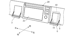
- FIG. 2 is a perspective view showing an internal configuration of a vehicle to which the image display system of FIG. 1 is applied.
- FIG. 2 is a block diagram showing the overall configuration of the image display system of FIG. 1.
- 4 is a flowchart showing an example of processing executed by the server device of FIG. 3.
- the image display device according to the embodiment of the present invention can be applied to mutually independent devices each having a display unit (monitor).
- a user terminal carried by a user and a display device mounted on a vehicle will be described.
- An example applied to the above will be described.
- FIG. 1 is a diagram schematically showing an overall configuration of an image display system having an image display device according to an embodiment of the present invention.
- the image display system 100 includes a user terminal 10 carried by a user 1, a display device 20 mounted on a vehicle 2, and a server device 30.
- the user terminal 10, the display device 20, and the server device 30 are connected to a network 4 including a public wireless communication network represented by the Internet network, a mobile phone network, etc., and can communicate with each other via the network 4.
- the network 4 also includes a closed communication network such as a wireless LAN or Wi-Fi (registered trademark) provided for each predetermined management area.
- the user terminal 10 is composed of various mobile terminals having a monitor as a display unit, such as a smartphone, a tablet terminal, a mobile phone, and a wearable terminal that are carried and used by the user 1.
- the user terminal 10 is configured to be thin and has a substantially rectangular shape as a whole, and a monitor is provided over substantially the entire one surface (see FIG. 4 ).
- the user terminal 10 is a user-specific terminal, and the user terminal 10 is provided with an identification ID (user ID) associated with the user 1 who uses the image display system 100.
- the display device 20 is composed of, for example, a navigation device having a navigation function for guiding a route to a destination.
- FIG. 2 is a perspective view showing a part of the instrument panel 5 which is arranged in the front part of the vehicle compartment facing the driver. In FIG. 2, the front-rear direction and the left-right direction of the vehicle 2 are indicated by arrows.
- a monitor 21 of the display device 20 is fixedly arranged at the center of the instrument panel 5 in the left-right direction.
- the monitor 21 has a substantially rectangular shape as a whole.
- Holders 6 and 7 for detachably holding the user terminal 10 are provided on the right and left sides of the monitor 21, respectively.
- the user 1 who gets in the vehicle 2 can arrange the user terminal 10 in the holders 6 and 7 (for example, the holder 6) with the surface of the monitor 11 facing the user as shown by the dotted line in FIG.
- the holders 6 and 7 are fixedly provided on the vehicle 2.
- the holders 6 and 7 may be movable.
- FIG. 3 is a block diagram showing the overall configuration of the image display system 100.
- the user terminal 10 communicates with a monitor 11 that displays various kinds of information, a GPS receiver 12 that detects the absolute position of the user terminal 10 based on a signal from a GPS satellite, and a network 4.
- the communication unit 13 for performing the above, a control unit 14 for controlling each unit of the user terminal 10, and a storage unit 15 for storing user-specific information such as a user ID.
- the user terminal 10 further includes an input unit for inputting various commands and information.
- the input unit can be composed of a touch panel, a keyboard, an acceleration sensor, a microphone, and various sensors and devices such as a camera.
- the user terminal 10 may have a display unit such as an indicator and a speaker.
- the user-specific information stored in the storage unit 15 includes an image of a predetermined avatar associated with the user 1, that is, an image personified as the alter ego of the user 1.
- This image is represented in the form of a predetermined character or agent, and is hereinafter referred to as an avatar image.
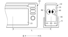
- FIG. 4 is a diagram showing an example of the avatar image 40 displayed on the monitor 11 of the user terminal 10.
- the user terminal 10 is arranged in the holder 6 on the right side of the display device 20.
- the avatar image 40 is composed of an image simulating the face of a character, more specifically, an image simulating the shape of a pair of left and right eyes (left eye image 41, right eye image 42). ..
- the avatar image 40 is not limited to this, and may not be divided into left and right, and may be an image that is asymmetrically divided into left and right. It may be an image simulating a body having a part or all of hands, legs, and torso instead of the face, or any image such as an image of a living thing such as a person or an animal, or a virtual creature that does not exist. Good.
- the form of the avatar image 40 can be changed according to the preference of the user.
- the avatar image 40 is not always displayed, but is displayed at a predetermined timing when the user terminal 10 is in a predetermined state. For example, immediately after the user terminal 10 is placed in the holder 6, the avatar image 40 is displayed in a predetermined size substantially in the center of the monitor 11, as shown in FIG.
- the user terminal 10 is not arranged in the holder 6, when the user terminal 10 is powered on, when the user terminal 10 receives a predetermined signal (for example, when an electronic mail is received), or when the user terminal 10 receives a predetermined signal.
- the avatar image 40 may be temporarily displayed on the monitor 11 when a command is input.
- the avatar image 40 can also be displayed as a standby screen of the user terminal 10. The position and size of the avatar image 40 can be appropriately changed and displayed on the monitor 11.
- the display of the monitor 11 is controlled by the control unit 14.
- the vehicle 2 includes a GPS receiver 25 that detects the absolute position of the vehicle 2 based on signals from GPS satellites, and a camera 26 that captures an image around the display device 20. And are provided. By analyzing the image of the camera 26, the position of the user terminal 10 around the display device 20 and the distance from the user terminal 10 to the display device 20 can be detected. When the absolute positions of the user terminal 10 and the display device 20 can be accurately detected by the GPS receivers 12 and 25, the user terminals 10 around the display device 20 are detected based on the signals from the GPS receivers 12 and 25. The position and the distance from the user terminal 10 to the display device 20 can also be detected.
- the signals from the GPS receiver 25 and the camera 26 are input to the display device 20.
- the display device 20 includes a monitor 21 that displays various kinds of information, a communication unit 22 that communicates via the network 4, and a control unit 23 that controls each unit of the display device 20. Although illustration is omitted, the display device 20 further includes an input unit that inputs various commands and information, and a storage unit that stores various information. The display on the monitor 21 is controlled by the control unit 23.
- the server device 30 constitutes a part of the image display device of this embodiment.
- the server device 30 is configured as, for example, a single server or a distributed server configured by separate servers for each function.
- the server device 30 may be configured as a distributed virtual server created in a cloud environment called a cloud server.
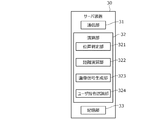
- the server device 30 is configured to include a communication unit 31, a calculation unit 32 such as a CPU as an operation circuit, a storage unit 33 such as ROM and RAM, and other peripheral circuits (interface circuit and the like).
- the communication unit 31 communicates with the user terminal 10 and the display device 20 via the network 4.
- the storage unit 33 stores a control program executed by the calculation unit 32, various threshold values used in the program, and the like. Information of the avatar image 40 associated with the user ID is also stored in the storage unit 33.
- the calculation unit 32 has a position determination unit 321, a distance calculation unit 322, and an image signal generation unit 323 as a functional configuration.
- the position determination unit 321 detects the relative position of the user terminal 10 with respect to the display device 20 based on the signals from the GPS receivers 12, 25 and the camera 26 acquired via the communication unit 31, and the user terminal 10 causes the holder 6 to move. , 7 is determined.
- a switch that is turned on when the user terminal 10 is placed is provided in the holders 6 and 7, and the position determination unit 321 determines whether the user terminal 10 is placed in the holder 6 or 7 based on a signal from the switch. You may do so.
- the distance calculation unit 322 monitors the user terminal 10 arranged in the holders 6, 7 as shown in FIG.
- the distance L from the center of 11 to the center of the monitor 21 of the display device 20 is calculated.
- the distance L (fixed value) from the center of the monitor 11 to the center of the monitor 21 is stored in advance in the storage unit of the display device 20, This may be transmitted to the server device 30.
- the distance L depends on the size of the monitors 11 and 21, but is set to, for example, about 0.1 m to 0.3 m.
- the image signal generation unit 323 displays on the monitors 11 and 21 based on the distance L calculated by the distance calculation unit 322.
- the avatar image 40 (FIG. 4) displayed on the central portion of the monitor 11 of the user terminal 10 is gradually shifted to the left with the passage of time, and is displayed on the central portion of the monitor 21 of the display device 20 after the moving time T.
- Image signal is generated as described above.
- an image signal is generated every predetermined time ⁇ t so that the avatar image 40 gradually moves from the monitor 11 to the monitor 21 at a predetermined image moving speed V.
- the moving time T is 1 second and the image is updated every 0.1 seconds as the predetermined time ⁇ t
- the distance L is divided into 10 equal parts and the image signal corresponding to the position of the avatar image 40 is obtained every 0.1 seconds.
- the image signal generated by the image signal generation unit 323 is transmitted to the user terminal 10 and the display device 20 via the communication unit 31.
- the image moving speed V is set to, for example, about 0.1 m to 0.3 m per second.
- the image moving speed V can be adjusted by the user operating an input unit provided on the user terminal 10 or the display device 20 for inputting various setting values.
- the user terminal 10 Upon receiving the image signal from the server device 30, the user terminal 10 causes the monitor 11 to display the avatar image 40 corresponding to the image signal by the processing in the control unit 14.
- the display device 20 Upon receiving the image signal from the server device 30, the display device 20 causes the monitor 21 to display the avatar image 40 corresponding to the image signal by the processing in the control unit 23. This causes the display on the monitors 11 and 21 to change.
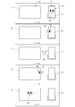
- FIG. 5 is a diagram showing an example of changes over time of the avatar image 40 displayed on the monitors 11 and 21.
- the avatar image 40 gradually moves to the left at a predetermined image moving speed V.
- V the left-eye image 41 is displayed on the left end portion of the monitor 11, and the right-eye image 42 is deleted from the monitor 11. That is, a part of the avatar image 40 is slid out from the monitor 11 toward the display device 20.
- the entire avatar image 40 is slid out from the monitor 11 to the left.
- the right eye image 42 is displayed on the right end portion of the monitor 21. That is, a part of the avatar image 40 is slid into the monitor 21 from the user terminal 10 side (right side).
- T the movement of the avatar image 40 is completed, and the entire avatar image 40 is displayed on the central portion of the monitor 21.
- FIG. 6 is a diagram showing an example of changes over time in the avatar image 40 displayed on the monitors 11 and 21 in this case.
- FIG. 6 starts from a state in which the user terminal 10 and the display device 20 are powered on, and the user terminal 10 is placed in the holder 7 on the left side of the display device 20.
- the avatar image 40 is displayed at the center of the monitor 21 of the display device 20.
- the avatar image 40 gradually moves to the left at a predetermined image moving speed V.
- the left-eye image 41 is displayed on the left end of the monitor 21, and the right-eye image 42 is deleted from the monitor 21. That is, a part of the avatar image 40 is slid out from the monitor 21 toward the user terminal 10.
- the entire avatar image 40 is slid out from the monitor 21 to the left.
- the right-eye image 42 is displayed on the right end portion of the monitor 11. That is, a part of the avatar image 40 is slid into the monitor 11 from the display device 20 side (right side).
- the movement of the avatar image 40 is completed, and the entire avatar image 40 is displayed on the central portion of the monitor 11.
- the image signal generation unit 323 generates an image signal corresponding to the above display of the avatar image 40.
- the avatar images 40 displayed on the monitors 11 and 21 are set to have the same size in FIGS. 5 and 6, the scale of the avatar images 40 is changed according to the size of the monitors 11 and 21. May be.
- the display device 20 may take over the settings of the voice and the like made by the user terminal 10. That is, when various settings of the user terminal 10 are made in association with the avatar image 40, various settings may be transferred to the display device 20 as the avatar image 40 moves.
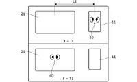
- the time T required to move the avatar image 40 in FIGS. 5 and 6 increases as the distance L between the monitor 11 and the monitor 21 increases.
- the moving time T of the avatar image 40 from the monitor 11 to the monitor 21 is T1.
- the moving time T of the avatar image 40 from the monitor 11 to the monitor 21 is T2 which is longer than T1.
- FIG. 8 is a flowchart showing an example of processing executed by the arithmetic unit 32 (CPU) of the server device 30 according to a program stored in advance. More specifically, it is a flowchart showing an example of a process relating to the movement of the avatar image 40 from the time when the user 1 gets on the vehicle 2 until the user gets off the vehicle 2.
- the process shown in this flowchart is started, for example, when the power of the display device 20 is turned on after the user 1 has boarded, and is repeated at a predetermined cycle.
- step S1 the signals from the GPS receivers 12 and 25 and the camera 26 acquired via the communication unit 31 are read. That is, the position information of the user terminal 10 and the display device 20 is read. At this time, the user ID included in the information transmitted from the user terminal 10 is also read.
- step S2 it is determined whether the user terminal 10 is placed in the right holder 6 based on the position information of the user terminal 10 and the display device 20. If the result in step S2 is affirmative, the process proceeds to step S3. If the result is negative, the process passes steps S3 and S4 and proceeds to step S5. In step S3, the distance L between the monitors 11 and 21 is calculated based on the positional information of the user terminal 10 and the display device 20.
- step S4 an image signal corresponding to the avatar image 40 to be displayed on the monitors 11 and 21 is generated every predetermined time ⁇ t based on the calculated distance L and the predetermined image moving speed V. ..
- the avatar image 40 corresponding to the user ID is specified.
- the position of the avatar image 40 from the monitor 11 to the monitor 21 is calculated every predetermined time ⁇ t, and an image signal corresponding to the position is generated.
- step S5 it is determined whether the user terminal 10 is placed in the left holder 7 based on the position information of the user terminal 10 and the display device 20. If the result in step S5 is affirmative, the process proceeds to step S6. If the result is negative, the process passes steps S6 and S7 and proceeds to step S8. In step S6, the distance L between the monitors 11 and 21 is calculated based on the positional information of the user terminal 10 and the display device 20, as in step S3.
- step S7 an image signal corresponding to the avatar image 40 to be displayed on the monitors 11 and 21 is generated every predetermined time ⁇ t based on the calculated distance L and the predetermined image moving speed V. ..
- the avatar image 40 corresponding to the user ID is specified.
- the position of the avatar image 40 from the monitor 21 toward the monitor 11 at every predetermined time ⁇ t is calculated, and an image signal corresponding to the position is generated.
- step S8 the image signal generated in step S4 or step S7 is transmitted to the user terminal 10 and the display device 20 via the communication unit 31, respectively.
- the control units 14 and 23 of the user terminal 10 and the display device 20 control the display of the monitors 11 and 21 according to the image signals transmitted respectively.
- the avatar image 40 is displayed on the monitors 11 and 21, for example, as shown in FIGS.
- the calculation unit 32 of the server device 30 may include a user command recognition unit 324 that recognizes a command input by the user.
- the user command recognition unit 324 makes a predetermined input by the user 1 to the input unit of the user terminal 10 based on the information transmitted from the user terminal 10. If it is determined that there is a predetermined input, the process may proceed to step S3 or step S6. That is, the server device 30 may generate the image signal on the condition of a predetermined input by the user 1.
- the predetermined input in this case includes operation input such as flick or tap on the touch panel, voice input such as utterance of a voice command to the microphone, and camera input such as a gesture within the visual field of the camera 26. Accordingly, the avatar image 40 can be moved at a timing desired by the user 1.
- a predetermined avatar image 40 is displayed on the monitor 11 of the user terminal 10 carried by the user 1 when the user terminal 10 is used. Therefore, the user 1 already has an affinity for the displayed avatar.
- the avatar image 40 displayed on the user terminal 10 is , Gradually move to the display device 20 side with the lapse of time. Then, after a predetermined time T, the avatar image 40 is displayed in the central portion of the monitor 21 of the display device 20 (step S4).
- the user 1 can feel as if the avatar had transferred from the user terminal 10 to the display device 20 without any discomfort.
- the avatar image 40 moves to the display device 20, thereafter, the avatar image 40 is displayed on the monitor 21 of the display device 20 constantly or at a predetermined timing. Therefore, the user 1 can feel the avatar close to him while he is in the vehicle, and the comfort when he is in the vehicle is improved.
- the movement of the avatar image 40 may be started when the user 1 makes a predetermined input to the input unit of the user terminal 10, whereby the avatar image 40 can be moved at a timing desired by the user 1. it can.
- the avatar image 40 of the display device 20 gradually moves to the user terminal 10 side over time. Then, after a predetermined time T, the avatar image 40 is displayed in the central portion of the monitor 11 of the user terminal 10 (step S7). Accordingly, the user 1 can feel as if the avatar returned from the display device 20 to the user terminal 10 without any discomfort.
- the movement of the avatar image 40 may be started when the user 1 makes a predetermined input to the input unit of the user terminal 10, whereby the avatar image 40 can be moved at a timing desired by the user 1. it can.
- the image display device controls the image 40 displayed on the monitor 11 provided on the user terminal 10 carried by the user 1 and the monitor 21 provided on the display device 20 of the vehicle 2.
- the GPS receivers 12, 25 and the camera 26 for detecting the position of the user terminal 10 with respect to 20 and whether the detected position of the user terminal 10 is at a predetermined position, that is, whether or not the holder 6 on the side of the display device 20 is arranged.
- a position determination unit 321 for determining, and an image signal generation unit 323 for controlling the display of the monitors 11 and 21 and control units 14 and 23 according to the determination result by the position determination unit 321 are provided (FIG. 3).
- the image signal generation unit 323 determines that the avatar image 40 is displayed on the monitor 11 and the user terminal 10 is placed in the holder 6 before the position determination unit 321 determines that the user terminal 10 is placed in the holder 6. Then, an image signal is transmitted to the user terminal 10 and the display device 20 so that the avatar image 40 is displayed while gradually moving from the monitor 11 to the monitor 21 over time, and control is performed according to the image signal.
- the units 14 and 23 control the images on the monitors 11 and 21 (FIGS. 5 and 8). With this configuration, the display of the avatar image 40 is automatically performed from the monitor 11 of the user terminal 10 to the monitor 21 of the display device 20 without the user 1 operating the user terminal 10 or the display device 20 to input an image movement command. Gradually move. Therefore, it is possible to prevent the user 1 from feeling uncomfortable with the display of the avatar image 40.
- the server device 30 may be configured to further include a user command recognition unit 324 that recognizes a command input by the user (FIG. 9).
- the server device 30 changes the avatar image 40 from the monitor 11 to the monitor 21 or from the monitor 21 to the monitor 11 with the lapse of time on condition that the input of the predetermined command is recognized by the user command recognition unit 324.
- the image signal is transmitted to the user terminal 10 and the display device 20 so as to be displayed while gradually moving. Accordingly, the avatar image 40 can be moved at a timing desired by the user 1.
- the GPS receivers 12 and 25 and the camera 26 are configured to detect the relative position of the user terminal 10 with respect to the display device 20, and the position of the holder 6 as the predetermined position is determined based on the display device 20.
- the moving direction of the avatar image 40 can be defined according to the relative position between the user terminal 10 and the display device 20. That is, when the user terminal 10 is arranged to the right of the display device 20, the avatar image 40 of the user terminal 10 moves from the right to the left toward the display device 20 and moves out of the monitor 11 (slide out). At the same time, the image can be displayed from the user terminal 10 side so that the avatar image 40 moves (slides in) into the monitor 21 of the display device 20. Therefore, the avatar image 40 moves smoothly, and the user 1 can recognize the movement of the avatar image 40 without a feeling of strangeness.
- the position determination unit 321 determines whether the user terminal 10 is further placed in the holder 7.
- the image signal generation unit 323 determines that the user terminal 10 is placed in the holder 6 by the position determination unit 321 and displays the avatar image 40 on the monitor 21 of the display device 20, and then the position determination unit 321 displays the user terminal 10
- an image signal is transmitted to the user terminal 10 and the display device 20 so that the avatar image 40 is displayed while gradually moving from the monitor 21 to the monitor 11 as time passes.
- the control units 14 and 23 control the images on the monitors 11 and 21 according to the image signals (FIGS. 6 and 8). As a result, the display of the avatar image 40 is gradually moved from the monitor 21 of the display device 20 to the monitor 11 of the user terminal 10, and the user 1 does not feel uncomfortable. It can be returned to the terminal 10.
- the holders 6 and 7 are arranged on the opposite sides of the display device 20, that is, on the left and right sides of the display device 20.
- the avatar image 40 slid into the monitor 21 from the right end portion of the monitor 21 is displayed when the user terminal 10 is placed in the left holder 7. From the left end of 21 slides out of the monitor 21. Therefore, the user 1 can intuitively understand the operation of moving the avatar image 40 from the user terminal 10 and the operation of returning the avatar image 40 to the user terminal 10.
- the moving direction of the avatar image 40 matches the right-to-left boarding direction of the user 1, the user 1 does not feel discomfort with the moving direction of the avatar image 40.
- the image display device further includes a distance calculation unit 322 that detects the distance L from the user terminal 10 to the display device 20 based on the signals from the GPS receivers 12 and 25 and the camera 26.
- the longer the detected distance L the longer the time T required for the image signal generation unit 323 to move the avatar image 40 from the monitor 11 of the user terminal 10 to the monitor 21 of the display device 20 or from the monitor 21 to the monitor 11.
- the image signal is transmitted to the user terminal 10 and the display device 20.
- the display of the avatar image 40 changes in accordance with the user's feeling.
- the image display device includes the holder 6 that holds the user terminal 10 at a predetermined position. Therefore, when the movement of the avatar image 40 is started under the condition that the user terminal 10 is arranged at the predetermined position, the avatar image 40 can be moved at a good timing.
- the display device 20 is mounted on the vehicle 2, and when the user terminal 10 is held by the holder 6 on the side of the display device 20 as the user 1 gets on the vehicle, the avatar image 40 of the user terminal 10 is displayed. It is moved to the monitor 21 of 20, and the function of realizing the display of the avatar is taken over by the display device 20.
- the avatar image 40 is an image unique to the user 1, and the display device 20 continuously displays the avatar image 40, so that the user 1 has a feeling that the user 1 acts with the avatar while riding, and the comfort of the user is improved. improves.
- the image display system 100 is configured by the user terminal 10, the display device 20, and the server device 30, but the display device 20 performs the function of the calculation unit 32 of the server device 30, for example, so that the user terminal
- the image display system 100 can also be configured by 10 and the display device 20.
- the image display device can also be configured by omitting the server device 30. Therefore, the display control unit may be configured by only the control units 14 and 23 of the image signal generation unit 323 and the control units 14 and 23.
- the image display device is displayed on the monitor 11 (first display unit) of the user terminal 10 as the first device and the monitor 21 (second display unit) of the display device 20 as the second device.
- the configurations of the first device and the second device are not limited to this.
- the position of the user terminal 10, more specifically, the relative position of the user terminal 10 with respect to the display device 20, is detected by the GPS receivers 12, 25 and the camera 26.
- the holders 6 and 7 are provided as holding units for holding the user terminal 10 at the predetermined value position of the vehicle 2, but the holding units may be provided at home, for example.
- the avatar image 40 is displayed on the monitor 21 after a time T corresponding to the distance from the holding unit to the display device 20. You should do so.
- the pair of holders 6 and 7 are arranged on the left and right, but they may be arranged on the top and bottom. In this case, the avatar image 40 may be moved up and down.
- the avatar image 40 is displayed on the monitors 11 and 21 as an image of a predetermined shape, but the image may have any form.
- the holders 6 and 7 in which the user terminals 10 are arranged are provided on the left and right sides of the display device 20, but the first position and the second position corresponding to the positions of the holders 6 and 7 are the same as those described above.
- the distance calculation unit 322 calculates the distance from the monitor 11 of the user terminal 10 to the monitor 21 of the display device 20 based on the signals from the GPS receivers 12 and 25 and the camera 26.
- the detector may have any configuration.
- the avatar image 40 is returned to the user terminal 10 by disposing the user terminal 10 in the holder 7, but once the user terminal 10 is removed from the holder 6, the user terminal 10 is again placed in the holder 6.
- the avatar image 40 may be returned to the user terminal 10.
- the camera 26 or the like detects that the user 1 has left the vehicle 2 for a predetermined time, or when the sensor or the like detects the operation of the parking brake of the vehicle 2, the avatar image 40 is displayed on the user terminal. You may make it return to 10 automatically.
- the image display device for controlling the images displayed on the monitor 11 provided on the user terminal 10 carried by the user and the monitor 21 provided on the display device 20 has been described above, but the present invention is carried by the user. It can also be configured as an image display method for controlling images displayed on the first display unit provided on the first device and the second display unit provided on the second device.
Landscapes
- Engineering & Computer Science (AREA)
- Chemical & Material Sciences (AREA)
- Combustion & Propulsion (AREA)
- Transportation (AREA)
- Mechanical Engineering (AREA)
- Theoretical Computer Science (AREA)
- General Engineering & Computer Science (AREA)
- Physics & Mathematics (AREA)
- General Physics & Mathematics (AREA)
- Human Computer Interaction (AREA)
- Signal Processing (AREA)
- Controls And Circuits For Display Device (AREA)
- User Interface Of Digital Computer (AREA)
Abstract
画像表示装置は、第1機器(10)の位置が所定位置であるか否かを判定する位置判定部(321)と、位置判定部(321)による判定結果に応じて第1機器(10)に設けられる第1表示部(11)および第2機器(20)に設けられる第2表示部(21)の表示画像を制御する表示制御部(14,23,323)と、を備える。表示制御部(14,23,323)は、位置判定部(321)により第1機器(10)が所定位置に位置すると判定される前は、第1表示部(11)に所定形状の画像が表示され、所定位置に位置すると判定されると、所定形状の画像が時間経過に伴い第1表示部(11)から第2表示部(21)へと徐々に移動しながら表示されるように第1表示部(11)および第2表示部(21)の表示画像を制御する。
Description
本発明は、複数の表示部に画像を表示させる画像表示装置、画像表示システムおよび画像表示方法に関する。
この種の装置として、従来、携帯端末のディスプレイと移動ロボットのディスプレイとに特定のキャラクタ画像を表示させるようにした装置が知られている(例えば特許文献1参照)。特許文献1記載の装置では、ユーザが命令を入力する命令モードで、携帯端末のディスプレイにキャラクタ画像を表示させ、ユーザを道案内する誘導モードで、ロボットのディスプレイにキャラクタ画像を表示させる。
しかしながら、上記特許文献1記載の装置では、命令モードから誘導モードへの切換時に、ユーザは、携帯端末のディスプレイからロボットのディスプレイへとキャラクタ画像があたかも瞬時に移動したものと感じやすく、表示の変化に対し違和感を抱く。
本発明の一態様は、ユーザが携帯する第1機器に設けられる第1表示部および第2機器に設けられる第2表示部に表示される画像を制御する画像表示装置であって、第1機器の位置を検出する位置検出部と、位置検出部により検出された第1機器の位置が所定位置であるか否かを判定する位置判定部と、位置判定部による判定結果に応じて第1表示部および第2表示部の表示画像を制御する表示制御部と、を備える。表示制御部は、位置判定部により第1機器が所定位置に位置すると判定される前は、第1表示部に所定形状の画像が表示され、位置判定部により第1機器が所定位置に位置すると判定されると、所定形状の画像が時間経過に伴い第1表示部から第2表示部へと徐々に移動しながら表示されるように第1表示部および第2表示部を制御する。
本発明の他の態様である画像表示システムは、第1表示部を有し、ユーザが携帯する第1機器と、第2表示部を有する第2機器と、第1機器の位置を検出する位置検出部と、位置検出部により検出された第1機器の位置が所定位置であるか否かを判定する位置判定部と、位置判定部による判定結果に応じて第1表示部および第2表示部を制御する表示制御部と、を備える。表示制御部は、位置判定部により第1機器が所定位置に位置すると判定される前は、第1表示部に所定形状の画像が表示され、位置判定部により第1機器が所定位置に位置すると判定されると、所定形状の画像が時間経過に伴い第1表示部から第2表示部へと徐々に移動しながら表示されるように第1表示部および第2表示部の表示画像を制御する。
本発明のさらに他の態様は、ユーザが携帯する第1機器に設けられる第1表示部と、第2機器に設けられる第2表示部とに、所定形状の画像を表示させる表示方法であって、位置検出部が、第1機器の位置を検出し、位置判定部が、検出された第1機器の位置が所定位置であるか否かを判定し、表示制御部が、判定結果に応じて第1表示部および第2表示部を制御することを含む。第1表示部および第2表示部を制御することは、第1機器が所定位置に位置すると判定される前は、第1表示部に所定形状の画像が表示され、第1機器が所定位置に位置すると判定されると、所定形状の画像が時間経過に伴い第1表示部から第2表示部へと徐々に移動しながら表示されるように第1表示部および第2表示部の表示画像を制御することを含む。
本発明によれば、第1機器の第1表示部と第2機器の第2表示部との間で、ユーザが違和感を抱くことなく画像表示を変化させることができる。
以下、図1~図9を参照して本発明の実施形態について説明する。本発明の実施形態に係る画像表示装置は、それぞれ表示部(モニタ)を有する互いに独立した機器に適用することができるが、以下では、ユーザが携帯するユーザ端末と車両に搭載された表示機器とに適用する例を説明する。
図1は、本発明の実施形態に係る画像表示装置を有する画像表示システムの全体構成を概略的に示す図である。図1に示すように、画像表示システム100は、ユーザ1が携帯するユーザ端末10と、車両2に搭載された表示機器20と、サーバ装置30とを有する。
ユーザ端末10、表示機器20およびサーバ装置30は、インターネット網や携帯電話網等に代表される公衆無線通信網を含むネットワーク4に接続され、ネットワーク4を介して互いに通信可能である。なお、ネットワーク4には、所定の管理地域ごとに設けられた閉鎖的な通信網、例えば無線LAN、Wi-Fi(登録商標)等も含まれる。
ユーザ端末10は、ユーザ1により携帯して使用されるスマートフォンやタブレット端末、携帯電話、さらにはウェアラブル端末等、表示部としてのモニタを有する各種携帯端末により構成される。例えばユーザ端末10は、全体が略矩形状の薄型に構成され、一の面のほぼ全体にわたってモニタが設けられる(図4参照)。ユーザ端末10はユーザ固有の端末であり、ユーザ端末10には、画像表示システム100を利用するユーザ1に紐づけられた識別ID(ユーザID)が付与される。
表示機器20は、例えば目的地までの経路誘導を行うナビゲーション機能を有するナビゲーション装置により構成される。図2は、車室内の前部に、運転者に面して配置されるインストルメントパネル5の一部を示す斜視図である。なお、図2には車両2の前後方向および左右方向を矢印で示す。図2に示すように、インストルメントパネル5の左右方向中央部には、表示機器20のモニタ21が固定的に配置される。モニタ21は全体が略矩形状を呈する。モニタ21の右側および左側には、それぞれユーザ端末10を着脱可能に保持するホルダ6,7が設けられる。車両2に乗車したユーザ1は、図2に点線で示すようにユーザ端末10を、そのモニタ11の表面をユーザに向けた状態でホルダ6,7(例えばホルダ6)に配置することができる。ホルダ6,7は車両2に固定的に設けられる。なお、ホルダ6,7を移動可能に構成してもよい。
図3は、画像表示システム100の全体構成を示すブロック図である。図3に示すように、ユーザ端末10は、各種情報を表示するモニタ11と、GPS衛星からの信号に基づいてユーザ端末10の絶対位置を検出するGPS受信機12と、ネットワーク4を介して通信を行う通信部13と、ユーザ端末10の各部を制御する制御部14と、ユーザIDなどのユーザ固有の情報を記憶する記憶部15とを有する。図示は省略するが、ユーザ端末10は、各種指令や情報を入力する入力部をさらに有する。入力部は、タッチパネル、キーボード、加速度センサー、マイクさらにカメラ等の各種センサーや機器によって構成することができる。インジケーター等の表示部、スピーカ等をユーザ端末10が有していてもよい。
記憶部15に記憶されるユーザ固有の情報には、ユーザ1に対応付けられた所定のアバタの画像、すなわち、ユーザ1の分身として擬人化された画像が含まれる。この画像は、所定のキャラクタまたはエージェントの形態で表され、以下、これをアバタ画像と呼ぶ。図4は、ユーザ端末10のモニタ11に表示されるアバタ画像40の一例を示す図である。なお、図4では、ユーザ端末10が表示機器20の右側のホルダ6に配置されている。
図4に示すように、アバタ画像40は、キャラクタの顔面を模した画像、より具体的には左右一対の目の形状を模した画像(左眼画像41、右眼画像42)により構成される。なお、アバタ画像40はこれに限らず、左右に分割されていなくてもよく、左右非対称に分割される画像であってもよい。顔面ではなく、手、脚、胴体の一部あるいは全部を有する身体を模した画像であってもよく、人や動物などの生物、あるいは現存しない仮想の生物の画像等、いかなる画像であってもよい。アバタ画像40の形態は、ユーザの好みに応じて変更することができる。
アバタ画像40は常に表示されるものではなく、ユーザ端末10が所定状態であるときに、所定のタイミングで表示される。例えばユーザ端末10がホルダ6に配置された直後に、アバタ画像40は、図4に示すようにモニタ11のほぼ中央に所定の大きさで表示される。ユーザ端末10がホルダ6に配置されていない場合、ユーザ端末10の電源オン時や、ユーザ端末10が所定の信号を受信したとき(例えば電子メールを受信したとき)、あるいはユーザ端末10に所定の指令を入力したときなどに、アバタ画像40がモニタ11に一時的に表示されるようにしてもよい。ユーザ端末10の待ち受け画面としてアバタ画像40を表示することもできる。アバタ画像40の位置や大きさを適宜変更してモニタ11に表示することもできる。モニタ11の表示は、制御部14により制御される。
図3に示すように、車両2には、表示機器20の他、GPS衛星からの信号に基づいて車両2の絶対位置を検出するGPS受信機25と、表示機器20の周囲を撮影するカメラ26とが設けられる。カメラ26の画像を解析することにより、表示機器20の周囲のユーザ端末10の位置およびユーザ端末10から表示機器20までの距離を検出することができる。なお、GPS受信機12,25によりユーザ端末10および表示機器20のそれぞれの絶対位置を精度よく検出できる場合、GPS受信機12,25からの信号に基づいて、表示機器20の周囲のユーザ端末10の位置およびユーザ端末10から表示機器20までの距離を検出することもできる。
GPS受信機25とカメラ26とからの信号は表示機器20に入力される。表示機器20は、各種情報を表示するモニタ21と、ネットワーク4を介して通信を行う通信部22と、表示機器20の各部を制御する制御部23とを有する。図示は省略するが、表示機器20は、各種指令や情報を入力する入力部、各種情報を記憶する記憶部をさらに有する。モニタ21の表示は制御部23により制御される。
サーバ装置30は、本実施形態の画像表示装置の一部を構成する。サーバ装置30は、例えば単一のサーバとして、あるいは機能ごとに別々のサーバから構成される分散サーバとして構成される。クラウドサーバと呼ばれるクラウド環境に作られた分散型の仮想サーバとしてサーバ装置30を構成することもできる。サーバ装置30は、通信部31と、動作回路としてのCPUなどの演算部32と、ROM,RAMなどの記憶部33と、その他の周辺回路(インターフェース回路等)とを含んで構成される。
通信部31は、ネットワーク4を介してユーザ端末10および表示機器20とそれぞれ通信を行う。記憶部33は、演算部32で実行される制御プログラムや、プログラムで用いられる各種閾値等を記憶する。記憶部33には、ユーザIDに対応付けられたアバタ画像40の情報も記憶される。演算部32は、機能的構成として位置判定部321と、距離演算部322と、画像信号生成部323とを有する。
位置判定部321は、通信部31を介して取得したGPS受信機12,25およびカメラ26からの信号に基づいて表示機器20に対するユーザ端末10の相対位置を検出し、ユーザ端末10が、ホルダ6,7に配置されているか否かを判定する。ホルダ6,7に、ユーザ端末10が配置されるとオンするスイッチを設け、位置判定部321が、スイッチの信号に基づいて、ユーザ端末10がホルダ6,7に配置されているか否かを判定するようにしてもよい。
距離演算部322は、通信部31を介して取得したGPS受信機12,25およびカメラ26からの信号に基づいて、図4に示すように、ホルダ6,7に配置されたユーザ端末10のモニタ11の中央部から表示機器20のモニタ21の中央部までの距離Lを演算する。表示機器20に対するホルダ6,7の位置が固定されているとき、モニタ11の中央部からモニタ21の中央部までの距離L(固定値)を予め表示機器20の記憶部に記憶しておき、これをサーバ装置30に送信するようにしてもよい。距離Lはモニタ11,21の大きさなどに依存するが、例えば0.1m~0.3m程度に設定される。
画像信号生成部323は、位置判定部321によりユーザ端末10がホルダ6,7に配置されたと判定されると、距離演算部322により演算された距離Lに基づいて、各モニタ11,21に表示すべきアバタ画像40に対応する画像信号を生成する。より具体的には、まず、記憶部33に記憶されたユーザIDとアバタ画像40との対応関係の情報に基づき、ユーザ端末10から送信された信号に含まれるユーザIDに対応するアバタ画像40の形態(形状等)を特定する。さらに、ユーザ端末10が右側のホルダ6に配置されたとき、距離演算部322により演算された距離Lを、所定の速さ(画像移動速度V)で除算して移動時間Tを算出する(T=L/V)。そして、ユーザ端末10のモニタ11の中央部に表示されたアバタ画像40(図4)が、時間経過に伴い徐々に左方にずれ、移動時間T後に表示機器20のモニタ21の中央部に表示されるように画像信号を生成する。
換言すると、アバタ画像40があたかもモニタ11からモニタ21へと所定の画像移動速度Vで徐々に移動するように所定時間Δt毎の画像信号を生成する。例えば移動時間Tが1秒で、所定時間Δtとして0.1秒毎に画像を更新するとき、距離Lを10等分し、0.1秒毎のアバタ画像40の位置に対応する画像信号を生成する。画像信号生成部323で生成した画像信号は、通信部31を介してユーザ端末10と表示機器20とにそれぞれ送信される。なお、画像移動速度Vは、例えば1秒当たり0.1m~0.3m程度に設定される。画像移動速度Vは、ユーザがユーザ端末10または表示機器20に設けられた、各種設定値を入力するための入力部を操作することにより調整することが可能である。
ユーザ端末10は、サーバ装置30から画像信号を受信すると、制御部14での処理により、画像信号に応じたアバタ画像40をモニタ11に表示させる。表示機器20は、サーバ装置30から画像信号を受信すると、制御部23での処理により、画像信号に応じたアバタ画像40をモニタ21に表示させる。これによりモニタ11,21の表示が変化する。
図5は、モニタ11,21に表示されるアバタ画像40の時間経過に伴う変化の一例を示す図である。図5は、ユーザ端末10および表示機器20の電源がそれぞれオンされている状態で、表示機器20の右側のホルダ6にユーザ端末10が配置された状態から開始される。図5に示すように、初期時点(t=0)では、ユーザ端末10のモニタ11の中央部にアバタ画像40が表示される。
その後、t=t1,t2,t3およびTへと時間が経過する伴い、アバタ画像40が所定の画像移動速度Vで徐々に左側に移動する。例えば時点t1では、左眼画像41がモニタ11の左端部に表示され、右眼画像42がモニタ11から消去される。すなわちアバタ画像40の一部がモニタ11から表示機器20の方向にスライドアウトされる。時点t2では、アバタ画像40の全体がモニタ11から左方にスライドアウトされる。時点t3では、右眼画像42がモニタ21の右端部に表示される。すなわち、アバタ画像40の一部がユーザ端末10側(右側)からモニタ21にスライドインされる。その後、時点Tで、アバタ画像40の移動が完了し、アバタ画像40の全体がモニタ21の中央部に表示される。
アバタ画像40のモニタ21への移動が完了した後、ユーザ端末10が左側のホルダ7(図2)に配置されると、アバタ画像40の表示は以下のように変化する。図6は、この場合のモニタ11,21に表示されるアバタ画像40の時間経過に伴う変化の一例を示す図である。図6は、ユーザ端末10および表示機器20の電源がそれぞれオンされている状態で、表示機器20の左側のホルダ7にユーザ端末10が配置された状態から開始される。図6に示すように、初期時点(t=0)では、表示機器20のモニタ21の中央部にアバタ画像40が表示される。
その後、t=t11,t12,t13およびTへと時間が経過するのに伴い、アバタ画像40が所定の画像移動速度Vで徐々に左側に移動する。例えば時点t11では、左眼画像41がモニタ21の左端部に表示され、右眼画像42がモニタ21から消去される。すなわちアバタ画像40の一部がモニタ21からユーザ端末10の方向にスライドアウトされる。時点t12では、アバタ画像40の全体がモニタ21から左方にスライドアウトされる。時点t13では、右眼画像42がモニタ11の右端部に表示される。すなわち、アバタ画像40の一部が表示機器20側(右側)からモニタ11にスライドインされる。その後、時点Tで、アバタ画像40の移動が完了し、アバタ画像40の全体がモニタ11の中央部に表示される。
画像信号生成部323は、以上のアバタ画像40の表示に対応する画像信号を生成する。なお、図5、6では、モニタ11,21に表示されるアバタ画像40を互いに同一の大きさに設定したが、モニタ11,21の大きさに応じてアバタ画像40の縮尺を変更するようにしてもよい。アバタ画像40がユーザ端末10から表示機器20に移動した後は、ユーザ端末10による音声等の設定を、表示機器20が引き継ぐようにしてもよい。すなわち、アバタ画像40に対応付けてユーザ端末10の各種設定が行われているとき、アバタ画像40の移動に伴い各種設定が表示機器20に移行するようにしてもよい。
図5,6のアバタ画像40の移動に要する時間Tは、モニタ11とモニタ21との間の距離Lが長いほど長くなる。例えば図7Aに示すように、一対のモニタ11,21間の距離LがL1であるとき、モニタ11からモニタ21へのアバタ画像40の移動時間TはT1となる。一方、図7Bに示すように、一対のモニタ11,21間の距離LがL1より長いL2であるとき、モニタ11からモニタ21へのアバタ画像40の移動時間TはT1より長いT2となる。
図8は、予め記憶されたプログラムに従いサーバ装置30の演算部32(CPU)で実行される処理の一例を示すフローチャートである。より詳しくは、ユーザ1が車両2に乗車してから降車するまでの間のアバタ画像40の移動に係る処理の一例を示すフローチャートである。このフローチャートに示す処理は、例えばユーザ1が乗車後に表示機器20の電源がオンされると開始され、所定周期で繰り返される。図8に示すように、まず、ステップS1で、通信部31を介して取得したGPS受信機12,25およびカメラ26からの信号を読み込む。すなわち、ユーザ端末10および表示機器20の位置情報を読み込む。このとき、ユーザ端末10から送信された情報に含まれるユーザIDも読み込む。
次いで、ステップS2で、ユーザ端末10および表示機器20の位置情報に基づいて右側のホルダ6にユーザ端末10が配置されたか否かを判定する。ステップS2で肯定されるとステップS3に進み、否定されるとステップS3、ステップS4をパスしてステップS5に進む。ステップS3では、ユーザ端末10および表示機器20の位置情報に基づいてモニタ11,21間の距離Lを演算する。
次いで、ステップS4で、演算された距離Lと、予め定められた画像移動速度Vとに基づいて、所定時間Δt毎にモニタ11,21に表示すべきアバタ画像40に対応する画像信号を生成する。この場合、まずユーザIDに対応するアバタ画像40を特定する。そして、図5に示すように、モニタ11からモニタ21に向かう所定時間Δt毎のアバタ画像40の位置を演算し、その位置に対応する画像信号を生成する。
次いで、ステップS5で、ユーザ端末10および表示機器20の位置情報に基づいて左側のホルダ7にユーザ端末10が配置されたか否かを判定する。ステップS5で肯定されるとステップS6に進み、否定されるとステップS6、ステップS7をパスしてステップS8に進む。ステップS6では、ステップS3と同様、ユーザ端末10および表示機器20の位置情報に基づいてモニタ11,21間の距離Lを演算する。
次いで、ステップS7で、演算された距離Lと、予め定められた画像移動速度Vとに基づいて、所定時間Δt毎にモニタ11,21に表示すべきアバタ画像40に対応する画像信号を生成する。この場合、まずユーザIDに対応するアバタ画像40を特定する。そして、図6に示すように、モニタ21からモニタ11に向かう所定時間Δt毎のアバタ画像40の位置を演算し、その位置に対応する画像信号を生成する。
次いで、ステップS8で、ステップS4またはステップS7で生成された画像信号を、通信部31を介してユーザ端末10および表示機器20にそれぞれ送信する。ユーザ端末10および表示機器20の制御部14,23は、それぞれ送信された画像信号に応じてモニタ11,21の表示を制御する。これにより例えば図5,6に示すように、モニタ11,21にアバタ画像40が表示される。
なお、図9に示すように、サーバ装置30の演算部32が、ユーザから入力される指令を認識するユーザ指令認識部324を有するようにしてもよい。この場合、ステップS3またはステップS6の処理が実行される前に、ユーザ端末10から送信される情報に基づいて、ユーザ指令認識部324が、ユーザ端末10の入力部にユーザ1による所定の入力があったか否かを判定し、所定の入力があったと判定されると、ステップS3またはステップS6へ進むようにしてもよい。すなわち、ユーザ1による所定の入力を条件として、サーバ装置30が画像信号を生成するようにしてもよい。この場合の所定の入力には、タッチパネルへのフリックやタップなどの操作入力、マイクへの音声コマンドの発話などの音声入力、カメラ26の視野内でのジェスチャーなどのカメラ入力などが含まれる。これにより、ユーザ1が所望するタイミングでアバタ画像40を移動させることができる。
本実施形態に係る画像表示装置の動作をより具体的に説明する。ユーザ1が携帯するユーザ端末10のモニタ11には、ユーザ端末10の使用時等に所定のアバタ画像40が表示される。したがって、ユーザ1は、表示されるアバタに対し既に親近感を抱いている。このようなユーザ1が、車両2に乗車して右側のホルダ6にユーザ端末10を置き、ナビゲーション機能などを有する表示機器20の使用を開始すると、ユーザ端末10に表示されていたアバタ画像40は、時間経過に伴い徐々に表示機器20側に移動する。そして、所定時間T後に、アバタ画像40は表示機器20のモニタ21の中央部に表示される(ステップS4)。
このようにアバタ画像40が徐々に移動することにより、ユーザ1は、アバタがユーザ端末10から表示機器20へ乗り移ったかのように違和感なく感じることができる。アバタ画像40が表示機器20に移動すると、以降、表示機器20のモニタ21には常時あるは所定のタイミングでアバタ画像40が表示される。このため、ユーザ1は乗車中にアバタを身近に感じることができ、乗車時の快適性が高まる。なお、ユーザ1によるユーザ端末10の入力部への所定の入力があるときにアバタ画像40の移動を開始させてもよく、これにより、ユーザ1が所望するタイミングでアバタ画像40を移動させることができる。
その後、例えばユーザ1が車両2を降車する際に、ユーザ端末10を左側のホルダ7に置くと、表示機器20のアバタ画像40は、時間経過に伴い徐々にユーザ端末10側に移動する。そして、所定時間T後に、アバタ画像40はユーザ端末10のモニタ11の中央部に表示される(ステップS7)。これにより、ユーザ1は、アバタが表示機器20からユーザ端末10へ戻ったかのように違和感なく感じることができる。なお、ユーザ1によるユーザ端末10の入力部への所定の入力があるときにアバタ画像40の移動を開始させてもよく、これにより、ユーザ1が所望するタイミングでアバタ画像40を移動させることができる。
本実施形態によれば以下のような作用効果を奏することができる。
(1)画像表示装置は、ユーザ1が携帯するユーザ端末10に設けられるモニタ11と、車両2の表示機器20に設けられるモニタ21とに表示される画像40を制御するものであり、表示機器20に対するユーザ端末10の位置を検出するGPS受信機12,25およびカメラ26と、検出されたユーザ端末10の位置が所定位置、すなわち表示機器20の側方のホルダ6に配置されたか否かを判定する位置判定部321と、位置判定部321による判定結果に応じてモニタ11,21の表示を制御する画像信号生成部323および制御部14,23とを備える(図3)。画像信号生成部323は、位置判定部321によりユーザ端末10がホルダ6に配置されたと判定される前は、モニタ11にアバタ画像40が表示され、ユーザ端末10がホルダ6に配置されたと判定されると、アバタ画像40が時間経過に伴いモニタ11からモニタ21へと徐々に移動しながら表示されるようにユーザ端末10と表示機器20とに画像信号を送信し、この画像信号に応じて制御部14,23がモニタ11,21の画像を制御する(図5,8)。この構成により、ユーザ1がユーザ端末10や表示機器20等を操作して画像移動指令を入力することなく、アバタ画像40の表示がユーザ端末10のモニタ11から表示機器20のモニタ21へと自動的に徐々に移動する。したがって、ユーザ1がアバタ画像40の表示に対し違和感を抱くことを防止できる。
(1)画像表示装置は、ユーザ1が携帯するユーザ端末10に設けられるモニタ11と、車両2の表示機器20に設けられるモニタ21とに表示される画像40を制御するものであり、表示機器20に対するユーザ端末10の位置を検出するGPS受信機12,25およびカメラ26と、検出されたユーザ端末10の位置が所定位置、すなわち表示機器20の側方のホルダ6に配置されたか否かを判定する位置判定部321と、位置判定部321による判定結果に応じてモニタ11,21の表示を制御する画像信号生成部323および制御部14,23とを備える(図3)。画像信号生成部323は、位置判定部321によりユーザ端末10がホルダ6に配置されたと判定される前は、モニタ11にアバタ画像40が表示され、ユーザ端末10がホルダ6に配置されたと判定されると、アバタ画像40が時間経過に伴いモニタ11からモニタ21へと徐々に移動しながら表示されるようにユーザ端末10と表示機器20とに画像信号を送信し、この画像信号に応じて制御部14,23がモニタ11,21の画像を制御する(図5,8)。この構成により、ユーザ1がユーザ端末10や表示機器20等を操作して画像移動指令を入力することなく、アバタ画像40の表示がユーザ端末10のモニタ11から表示機器20のモニタ21へと自動的に徐々に移動する。したがって、ユーザ1がアバタ画像40の表示に対し違和感を抱くことを防止できる。
(2)サーバ装置30は、ユーザから入力される指令を認識するユーザ指令認識部324をさらに備えるように構成することもできる(図9)。この場合、サーバ装置30は、ユーザ指令認識部324により所定の指令の入力が認識されたことを条件としてアバタ画像40が時間経過に伴いモニタ11からモニタ21へと、あるいはモニタ21からモニタ11へと、徐々に移動しながら表示されるようにユーザ端末10と表示機器20とに画像信号を送信する。これにより、ユーザ1が所望するタイミングでアバタ画像40を移動させることができる。
(3)GPS受信機12,25およびカメラ26は、表示機器20に対するユーザ端末10の相対位置を検出するように構成され、所定位置としてのホルダ6の位置は、表示機器20を基準にして定められる。これにより、ユーザ端末10と表示機器20との相対位置に応じてアバタ画像40の移動方向を規定することができる。すなわち、表示機器20の右方にユーザ端末10が配置されると、ユーザ端末10のアバタ画像40が表示機器20に向けて右から左へと移動して、モニタ11外に移動(スライドアウト)するとともに、ユーザ端末10側から表示機器20のモニタ21内にアバタ画像40が移動(スライドイン)するように画像を表示させることができる。したがって、アバタ画像40がスムーズに移動し、ユーザ1はアバタ画像40の移動を違和感なく認識できる。
(4)位置判定部321は、ユーザ端末10がさらにホルダ7に配置されたか否かを判定する。画像信号生成部323は、位置判定部321によりユーザ端末10がホルダ6に配置されたと判定されてアバタ画像40が表示機器20のモニタ21に表示された後、位置判定部321によりユーザ端末10がホルダ7に配置されたと判定されると、アバタ画像40が時間経過に伴いモニタ21からモニタ11へと徐々に移動しながら表示されるようにユーザ端末10と表示機器20とに画像信号を送信し、この画像信号に応じて制御部14,23がモニタ11,21の画像を制御する(図6,8)。これにより、アバタ画像40の表示が表示機器20のモニタ21からユーザ端末10のモニタ11へと自動的に徐々に移動するようになり、ユーザ1が違和感を抱くことなくアバタ画像40を元のユーザ端末10に戻すことができる。
(5)ホルダ6,7は、表示機器20を挟んで互いに反対側、すなわち表示機器20の左右両側に配置される。これによりユーザ端末10が右側のホルダ6に配置されたときに、モニタ21の右端部からモニタ21内にスライドインしたアバタ画像40が、ユーザ端末10が左側のホルダ7に配置されたときには、モニタ21の左端部からモニタ21外にスライドアウトするようになる。したがって、ユーザ1は、アバタ画像40をユーザ端末10から移す操作およびユーザ端末10に戻す操作を、直感的に把握することができる。また、アバタ画像40の移動方向はユーザ1の右から左への乗車方向と合致しているため、ユーザ1はアバタ画像40の移動方向に対する違和感がない。
(6)画像表示装置は、GPS受信機12,25とカメラ26とからの信号に基づいてユーザ端末10から表示機器20までの距離Lを検出する距離演算部322をさらに備える。画像信号生成部323は、検出された距離Lが長いほど、ユーザ端末10のモニタ11から表示機器20のモニタ21またはモニタ21からモニタ11へのアバタ画像40の移動に要する時間Tが長くなるようにユーザ端末10および表示機器20に画像信号を送信する。これによりアバタ画像40の表示が、ユーザの感覚に良好に一致して変化するようになる。
(7)画像表示装置は、ユーザ端末10を所定位置に保持するホルダ6を備える。したがって、ユーザ端末10が所定位置に配置されることを条件としてアバタ画像40の移動を開始するとき、アバタ画像40をタイミングよく移動させることができる。
(8)表示機器20は車両2に搭載されており、ユーザ1の乗車に伴いユーザ端末10が表示機器20の側方のホルダ6に保持されると、ユーザ端末10のアバタ画像40が表示機器20のモニタ21に移され、アバタの表示を実現する機能が表示機器20に引き継がれる。アバタ画像40はユーザ1にとって固有の画像であり、表示機器20がアバタ画像40を引き続き表示することで、ユーザ1は乗車中もアバタと行動を共にするという感覚が得られ、ユーザの快適性が向上する。
なお、上記実施形態では、ユーザ端末10と表示機器20とサーバ装置30とにより画像表示システム100を構成したが、サーバ装置30の演算部32における機能を例えば表示機器20が担うことで、ユーザ端末10と表示機器20とにより画像表示システム100を構成することもできる。画像表示装置も、サーバ装置30を省略して構成することができる。したがって、画像信号生成部323と制御部14,23のうち、制御部14,23のみで、表示制御部を構成してもよい。上記実施形態では、画像表示装置が、第1機器としてのユーザ端末10のモニタ11(第1表示部)と第2機器としての表示機器20のモニタ21(第2表示部)とに表示される画像を制御するようにしたが、第1機器および第2機器の構成はこれに限らない。
上記実施形態では、GPS受信機12,25やカメラ26によりユーザ端末10の位置、より詳しくは表示機器20に対するユーザ端末10の相対位置を検出するようにしたが、位置検出部の構成はこれに限らない。上記実施形態では、ユーザ端末10を車両2の所定値位置に保持する保持部としてホルダ6,7を設けたが、保持部を例えば自宅に設けてもよい。この場合、ユーザ1がユーザ端末10を自宅の保持部に置いた後、車両2に乗車すると、保持部から表示機器20までの距離に応じた時間T後に、モニタ21にアバタ画像40が表示されるようにすればよい。上記実施形態では、一対のホルダ6,7を左右に配置したが、上下に配置してもよい。この場合、アバタ画像40が上下に移動されるようにしてもよい。上記実施形態では、モニタ11,21に所定形状の画像としてアバタ画像40を表示したが、画像の形態はいかなるものでもよい。
上記実施形態では、表示機器20の左右両側に、ユーザ端末10が配置されるホルダ6,7を設けたが、ホルダ6,7の位置に対応する第1位置および第2位置は、上述したものに限らない。上記実施形態では、GPS受信機12,25やカメラ26からの信号に基づいて距離演算部322がユーザ端末10のモニタ11から表示機器20のモニタ21までの距離を演算するようにしたが、距離検出部の構成はいかなるものでもよい。上記実施形態では、ユーザ端末10がホルダ7に配置されることにより、アバタ画像40をユーザ端末10に戻すようにしたが、ホルダ6から一旦ユーザ端末10を取り外した後、再びホルダ6にユーザ端末10を配置すると、アバタ画像40がユーザ端末10に戻るようにしてもよい。カメラ26等により、ユーザ1が車両2から離れて所定時間が経過したことが検出されると、あるいは、センサ等により、車両2の駐車ブレーキの作動が検出されると、アバタ画像40がユーザ端末10に自動的に戻るようにしてもよい。
以上では、ユーザが携帯するユーザ端末10に設けられるモニタ11と、表示機器20に設けられるモニタ21とに表示される画像を制御する画像表示装置について説明したが、本発明は、ユーザが携帯する第1機器に設けられる第1表示部および第2機器に設けられる第2表示部に表示される画像を制御する画像表示方法としても構成することができる。
以上の説明はあくまで一例であり、本発明の特徴を損なわない限り、上述した実施形態および変形例により本発明が限定されるものではない。上記実施形態と変形例の1つまたは複数を任意に組み合わせることも可能であり、変形例同士を組み合わせることも可能である。
6,7 ホルダ、10 ユーザ端末、11 モニタ、12 GPS受信機、14 制御部、20 表示機器、21 モニタ、23 制御部、25 GPS受信機、26 カメラ、30 サーバ装置、40 アバタ画像、100 画像表示システム、321 位置判定部、322 距離演算部、323 画像信号生成部
Claims (11)
- ユーザが携帯する第1機器に設けられる第1表示部と、第2機器に設けられる第2表示部とに表示される画像を制御する画像表示装置であって、
前記第1機器の位置を検出する位置検出部と、
前記位置検出部により検出された前記第1機器の位置が所定位置であるか否かを判定する位置判定部と、
前記位置判定部による判定結果に応じて前記第1表示部および前記第2表示部の表示画像を制御する表示制御部と、を備え、
前記表示制御部は、前記位置判定部により前記第1機器が前記所定位置に位置すると判定される前は、前記第1表示部に所定形状の画像が表示され、前記位置判定部により前記第1機器が前記所定位置に位置すると判定されると、前記所定形状の画像が時間経過に伴い前記第1表示部から前記第2表示部へと徐々に移動しながら表示されるように前記第1表示部および前記第2表示部の表示画像を制御することを特徴とする画像表示装置。 - 請求項1に記載の画像表示装置において、
ユーザから入力される指令を認識するユーザ指令認識部をさらに備え、
前記表示制御部は、さらに前記ユーザ指令認識部により所定の指令の入力が認識されたことを条件として前記所定形状の画像が時間経過に伴い前記第1表示部から前記第2表示部へと徐々に移動しながら表示されるように前記第1表示部および前記第2表示部の表示画像を制御することを特徴とする画像表示装置。 - 請求項1に記載の画像表示装置において、
前記位置検出部は、前記第2機器に対する前記第1機器の相対位置を検出するように構成され、
前記所定位置は、前記第2機器を基準にして予め設定されることを特徴とする画像表示装置。 - 請求項3に記載の画像表示装置において、
前記所定位置は、第1位置であり、
前記位置判定部は、前記位置検出部により検出された前記第1機器の位置が前記第2機器を基準にして定められた第2位置であるか否かをさらに判定し、
前記表示制御部は、前記位置判定部により前記第1機器が前記第1位置に位置すると判定されて前記所定形状の画像が前記第2表示部に表示された後、前記位置判定部により前記第1機器の位置が前記第2位置に変化したと判定されると、前記所定形状の画像が時間経過に伴い前記第2表示部から前記第1表示部へと徐々に移動しながら表示されるように前記第1表示部および前記第2表示部の表示画像を制御することを特徴とする画像表示装置。 - 請求項4に記載の画像表示装置において、
ユーザから入力される指令を認識するユーザ指令認識部をさらに備え、
前記表示制御部は、さらに前記ユーザ指令認識部により所定の指令の入力が認識されたことを条件として前記所定形状の画像が時間経過に伴い前記第2表示部から前記第1表示部へと徐々に移動しながら表示されるように前記第1表示部および前記第2表示部の表示画像を制御することを特徴とする画像表示装置。 - 請求項5に記載の画像表示装置において、
前記第1位置および前記第2位置は、前記第2機器を挟んで互いに反対側に設定されることを特徴とする画像表示装置。 - 請求項2~6のいずれか1項に記載の画像表示装置において、
前記第1機器から前記第2機器までの距離を検出する距離検出部をさらに備え、
前記表示制御部は、前記距離検出部により検出された距離が長いほど、前記第1表示部から前記第2表示部または前記第2表示部から前記第1表示部への前記所定形状の画像の移動に要する時間が長くなるように前記第1表示部および前記第2表示部の表示画像を制御することを特徴とする画像表示装置。 - 請求項1~7のいずれか1項に記載の画像表示装置において、
前記第1機器を前記所定位置に保持する保持部をさらに備えることを特徴とする画像表示装置。 - 第1表示部を有し、ユーザが携帯する第1機器と、
第2表示部を有する第2機器と、
前記第1機器の位置を検出する位置検出部と、
前記位置検出部により検出された前記第1機器の位置が所定位置であるか否かを判定する位置判定部と、
前記位置判定部による判定結果に応じて前記第1表示部および前記第2表示部の表示画像を制御する表示制御部と、を備え、
前記表示制御部は、前記位置判定部により前記第1機器が前記所定位置に位置すると判定される前は、前記第1表示部に所定形状の画像が表示され、前記位置判定部により前記第1機器が前記所定位置に位置すると判定されると、前記所定形状の画像が時間経過に伴い前記第1表示部から前記第2表示部へと徐々に移動しながら表示されるように前記第1表示部および前記第2表示部の表示画像を制御することを特徴とする画像表示システム。 - 請求項9に記載の画像表示システムにおいて、
前記第2機器は、車両に搭載された表示機器であることを特徴とする画像表示システム。 - ユーザが携帯する第1機器に設けられる第1表示部および第2機器に設けられる第2表示部に表示される画像を制御する画像表示方法であって、
位置検出部が、前記第1機器の位置を検出し、
位置判定部が、検出された前記第1機器の位置が所定位置であるか否かを判定し、
表示制御部が、判定結果に応じて前記第1表示部および前記第2表示部の表示画像を制御することを含み、
前記第1表示部および前記第2表示部を制御することは、前記第1機器が前記所定位置に位置すると判定される前は、前記第1表示部に所定形状の画像が表示され、前記第1機器が前記所定位置に位置すると判定されると、前記所定形状の画像が時間経過に伴い前記第1表示部から前記第2表示部へと徐々に移動しながら表示されるように前記第1表示部および前記第2表示部の表示画像を制御することを含む特徴とする画像表示方法。
Priority Applications (3)
| Application Number | Priority Date | Filing Date | Title |
|---|---|---|---|
| JP2020562895A JP7108716B2 (ja) | 2018-12-27 | 2019-11-11 | 画像表示装置、画像表示システムおよび画像表示方法 |
| CN201980085683.6A CN113228157B (zh) | 2018-12-27 | 2019-11-11 | 图像显示装置、图像显示系统及图像显示方法 |
| US17/417,348 US11733951B2 (en) | 2018-12-27 | 2019-11-11 | Image display apparatus, image display system and image display method |
Applications Claiming Priority (2)
| Application Number | Priority Date | Filing Date | Title |
|---|---|---|---|
| JP2018243836 | 2018-12-27 | ||
| JP2018-243836 | 2018-12-27 |
Publications (1)
| Publication Number | Publication Date |
|---|---|
| WO2020137196A1 true WO2020137196A1 (ja) | 2020-07-02 |
Family
ID=71128939
Family Applications (1)
| Application Number | Title | Priority Date | Filing Date |
|---|---|---|---|
| PCT/JP2019/044049 Ceased WO2020137196A1 (ja) | 2018-12-27 | 2019-11-11 | 画像表示装置、画像表示システムおよび画像表示方法 |
Country Status (4)
| Country | Link |
|---|---|
| US (1) | US11733951B2 (ja) |
| JP (1) | JP7108716B2 (ja) |
| CN (1) | CN113228157B (ja) |
| WO (1) | WO2020137196A1 (ja) |
Cited By (1)
| Publication number | Priority date | Publication date | Assignee | Title |
|---|---|---|---|---|
| WO2025084012A1 (ja) * | 2023-10-20 | 2025-04-24 | 三菱自動車工業株式会社 | 車両のコミュニケーションシステム |
Families Citing this family (1)
| Publication number | Priority date | Publication date | Assignee | Title |
|---|---|---|---|---|
| DE102024108422A1 (de) | 2024-03-25 | 2025-09-25 | Audi Aktiengesellschaft | Verfahren zum Bereitstellen einer digitalen Animation eines vorgegebenen Graphikelements, Steuereinrichtung, Speichermedium, Kraftfahrzeug, Servervorrichtung, und System |
Citations (8)
| Publication number | Priority date | Publication date | Assignee | Title |
|---|---|---|---|---|
| JP2009194528A (ja) * | 2008-02-13 | 2009-08-27 | Canon Inc | 画像処理システム、画像処理装置、画像処理装置の制御方法及び画像処理プログラム |
| JP2009236934A (ja) * | 2006-05-23 | 2009-10-15 | Nec Corp | 表示装置、これを含んだ機器、プログラム及び表示方法 |
| JP2010068494A (ja) * | 2008-09-12 | 2010-03-25 | Olympus Imaging Corp | 携帯機器 |
| JP2013130982A (ja) * | 2011-12-21 | 2013-07-04 | Sharp Corp | 情報表示装置 |
| JP2014127772A (ja) * | 2012-12-25 | 2014-07-07 | Gree Inc | 端末特定方法、サーバ装置、プログラム及び端末特定システム |
| JP2014153782A (ja) * | 2013-02-05 | 2014-08-25 | Toshiba Corp | 表示処理装置、及び表示処理方法 |
| JP2016529607A (ja) * | 2013-07-25 | 2016-09-23 | トムソン ライセンシングThomson Licensing | オブジェクトを表示する方法と装置 |
| WO2018110854A1 (ko) * | 2016-12-15 | 2018-06-21 | 삼성전자 주식회사 | 서버, 휴대 단말 장치, 전자 장치 및 그 제어 방법 |
Family Cites Families (15)
| Publication number | Priority date | Publication date | Assignee | Title |
|---|---|---|---|---|
| JP3009395B1 (ja) | 1998-09-22 | 2000-02-14 | 株式会社エイ・ティ・アール知能映像通信研究所 | ユーザ誘導装置 |
| JP2003244343A (ja) * | 2002-02-21 | 2003-08-29 | Toyota Motor Corp | 表示装置、携帯端末及び情報表示システム |
| JP2010130669A (ja) * | 2008-12-01 | 2010-06-10 | Fujitsu Ten Ltd | 車載装置および無線通信システム |
| JP5086302B2 (ja) | 2009-05-08 | 2012-11-28 | ヤフー株式会社 | デバイス間でキャラクタが移動するデバイス及び通信システムの制御方法 |
| JP2010274813A (ja) * | 2009-05-29 | 2010-12-09 | Fujitsu Ten Ltd | 画像生成装置及び画像表示システム |
| JP2011013113A (ja) * | 2009-07-02 | 2011-01-20 | Fujitsu Ten Ltd | ナビゲーションシステム、車載機、ナビゲーション方法及びプログラム |
| US8947454B2 (en) * | 2009-11-04 | 2015-02-03 | Honda Motor Co., Ltd. | Display device for vehicle |
| FR2956547B1 (fr) * | 2010-02-15 | 2012-09-14 | Sagem Wireless | Procede et un systeme de transfert d'une image entre deux appareils de telephonie mobile |
| JP2012093887A (ja) * | 2010-10-26 | 2012-05-17 | Aisin Aw Co Ltd | 表示装置、表示方法、及び表示プログラム |
| JP2012244207A (ja) * | 2011-05-16 | 2012-12-10 | Nec Casio Mobile Communications Ltd | 携帯電子機器、携帯電子機器制御方法及びプログラム |
| US20150055564A1 (en) * | 2013-08-20 | 2015-02-26 | GM Global Technology Operations LLC | Methods and apparatus for configuration of a vehicle-based wireless signal transmission range |
| WO2017138278A1 (ja) * | 2016-02-12 | 2017-08-17 | 本田技研工業株式会社 | 画像表示装置および画像表示方法 |
| WO2017155219A1 (en) * | 2016-03-07 | 2017-09-14 | Lg Electronics Inc. | Vehicle control device mounted in vehicle and control method thereof |
| JP6361764B2 (ja) * | 2017-03-08 | 2018-07-25 | カシオ計算機株式会社 | 端末装置、端末制御方法及びプログラム |
| KR102014263B1 (ko) * | 2017-12-27 | 2019-10-21 | 엘지전자 주식회사 | 차량 제어 장치 및 그것을 포함하는 차량 |
-
2019
- 2019-11-11 CN CN201980085683.6A patent/CN113228157B/zh active Active
- 2019-11-11 JP JP2020562895A patent/JP7108716B2/ja active Active
- 2019-11-11 WO PCT/JP2019/044049 patent/WO2020137196A1/ja not_active Ceased
- 2019-11-11 US US17/417,348 patent/US11733951B2/en active Active
Patent Citations (8)
| Publication number | Priority date | Publication date | Assignee | Title |
|---|---|---|---|---|
| JP2009236934A (ja) * | 2006-05-23 | 2009-10-15 | Nec Corp | 表示装置、これを含んだ機器、プログラム及び表示方法 |
| JP2009194528A (ja) * | 2008-02-13 | 2009-08-27 | Canon Inc | 画像処理システム、画像処理装置、画像処理装置の制御方法及び画像処理プログラム |
| JP2010068494A (ja) * | 2008-09-12 | 2010-03-25 | Olympus Imaging Corp | 携帯機器 |
| JP2013130982A (ja) * | 2011-12-21 | 2013-07-04 | Sharp Corp | 情報表示装置 |
| JP2014127772A (ja) * | 2012-12-25 | 2014-07-07 | Gree Inc | 端末特定方法、サーバ装置、プログラム及び端末特定システム |
| JP2014153782A (ja) * | 2013-02-05 | 2014-08-25 | Toshiba Corp | 表示処理装置、及び表示処理方法 |
| JP2016529607A (ja) * | 2013-07-25 | 2016-09-23 | トムソン ライセンシングThomson Licensing | オブジェクトを表示する方法と装置 |
| WO2018110854A1 (ko) * | 2016-12-15 | 2018-06-21 | 삼성전자 주식회사 | 서버, 휴대 단말 장치, 전자 장치 및 그 제어 방법 |
Cited By (1)
| Publication number | Priority date | Publication date | Assignee | Title |
|---|---|---|---|---|
| WO2025084012A1 (ja) * | 2023-10-20 | 2025-04-24 | 三菱自動車工業株式会社 | 車両のコミュニケーションシステム |
Also Published As
| Publication number | Publication date |
|---|---|
| US11733951B2 (en) | 2023-08-22 |
| JP7108716B2 (ja) | 2022-07-28 |
| CN113228157A (zh) | 2021-08-06 |
| CN113228157B (zh) | 2024-07-12 |
| US20220075587A1 (en) | 2022-03-10 |
| JPWO2020137196A1 (ja) | 2021-10-28 |
Similar Documents
| Publication | Publication Date | Title |
|---|---|---|
| US20190251973A1 (en) | Speech providing method, speech providing system and server | |
| JP5187517B2 (ja) | 情報提供装置、情報提供方法およびプログラム | |
| US20180093673A1 (en) | Utterance device and communication device | |
| KR20180014641A (ko) | 셀프 밸런스 차량 관리 방법, 장치, 프로그램 및 저장매체 | |
| CN105599642A (zh) | 座椅自动调节方法、装置及终端 | |
| US20180316911A1 (en) | Information processing apparatus | |
| JPWO2019124158A1 (ja) | 情報処理装置、情報処理方法、プログラム、表示システム、及び移動体 | |
| JP7851370B2 (ja) | 情報処理システム | |
| EP3287868B1 (en) | Content discovery | |
| JP2019086805A (ja) | 車内システム | |
| JP7108716B2 (ja) | 画像表示装置、画像表示システムおよび画像表示方法 | |
| JP2018532628A (ja) | セルフバランスカーの制御方法、装置、プログラム及び記録媒体 | |
| JP2020130502A (ja) | 情報処理装置および情報処理方法 | |
| US20240087339A1 (en) | Information processing device, information processing system, and information processing method | |
| JP2018072030A (ja) | 車載装置、携帯端末特定方法 | |
| JP2009190613A (ja) | 車載表示装置 | |
| WO2019188336A1 (ja) | サービス提供システムおよびサービス提供方法 | |
| JP6657048B2 (ja) | 処理結果異常検出装置、処理結果異常検出プログラム、処理結果異常検出方法及び移動体 | |
| US20240083249A1 (en) | Information processing system | |
| CN112241237B (zh) | 图像显示装置、图像显示系统以及图像显示方法 | |
| US12482348B2 (en) | Information management device, information management method and storage medium | |
| US20240085207A1 (en) | Information processing system | |
| JP7550823B2 (ja) | 情報処理システム | |
| US20250296439A1 (en) | Cabin environment control apparatus | |
| JP2020201624A (ja) | 画像表示装置、画像表示システムおよび画像表示方法 |
Legal Events
| Date | Code | Title | Description |
|---|---|---|---|
| 121 | Ep: the epo has been informed by wipo that ep was designated in this application |
Ref document number: 19901594 Country of ref document: EP Kind code of ref document: A1 |
|
| ENP | Entry into the national phase |
Ref document number: 2020562895 Country of ref document: JP Kind code of ref document: A |
|
| NENP | Non-entry into the national phase |
Ref country code: DE |
|
| 122 | Ep: pct application non-entry in european phase |
Ref document number: 19901594 Country of ref document: EP Kind code of ref document: A1 |