WO2020137191A1 - 流路切換弁 - Google Patents
流路切換弁 Download PDFInfo
- Publication number
- WO2020137191A1 WO2020137191A1 PCT/JP2019/043942 JP2019043942W WO2020137191A1 WO 2020137191 A1 WO2020137191 A1 WO 2020137191A1 JP 2019043942 W JP2019043942 W JP 2019043942W WO 2020137191 A1 WO2020137191 A1 WO 2020137191A1
- Authority
- WO
- WIPO (PCT)
- Prior art keywords
- main valve
- valve body
- plate portion
- flow path
- pressing plate
- Prior art date
- Legal status (The legal status is an assumption and is not a legal conclusion. Google has not performed a legal analysis and makes no representation as to the accuracy of the status listed.)
- Ceased
Links
Images


Classifications
-
- F—MECHANICAL ENGINEERING; LIGHTING; HEATING; WEAPONS; BLASTING
- F16—ENGINEERING ELEMENTS AND UNITS; GENERAL MEASURES FOR PRODUCING AND MAINTAINING EFFECTIVE FUNCTIONING OF MACHINES OR INSTALLATIONS; THERMAL INSULATION IN GENERAL
- F16K—VALVES; TAPS; COCKS; ACTUATING-FLOATS; DEVICES FOR VENTING OR AERATING
- F16K11/00—Multiple-way valves, e.g. mixing valves; Pipe fittings incorporating such valves
- F16K11/02—Multiple-way valves, e.g. mixing valves; Pipe fittings incorporating such valves with all movable sealing faces moving as one unit
- F16K11/06—Multiple-way valves, e.g. mixing valves; Pipe fittings incorporating such valves with all movable sealing faces moving as one unit comprising only sliding valves, i.e. sliding closure elements
- F16K11/065—Multiple-way valves, e.g. mixing valves; Pipe fittings incorporating such valves with all movable sealing faces moving as one unit comprising only sliding valves, i.e. sliding closure elements with linearly sliding closure members
- F16K11/0655—Multiple-way valves, e.g. mixing valves; Pipe fittings incorporating such valves with all movable sealing faces moving as one unit comprising only sliding valves, i.e. sliding closure elements with linearly sliding closure members with flat slides
-
- F—MECHANICAL ENGINEERING; LIGHTING; HEATING; WEAPONS; BLASTING
- F16—ENGINEERING ELEMENTS AND UNITS; GENERAL MEASURES FOR PRODUCING AND MAINTAINING EFFECTIVE FUNCTIONING OF MACHINES OR INSTALLATIONS; THERMAL INSULATION IN GENERAL
- F16K—VALVES; TAPS; COCKS; ACTUATING-FLOATS; DEVICES FOR VENTING OR AERATING
- F16K31/00—Actuating devices; Operating means; Releasing devices
- F16K31/12—Actuating devices; Operating means; Releasing devices actuated by fluid
- F16K31/122—Actuating devices; Operating means; Releasing devices actuated by fluid the fluid acting on a piston
- F16K31/1225—Actuating devices; Operating means; Releasing devices actuated by fluid the fluid acting on a piston with a plurality of pistons
-
- F—MECHANICAL ENGINEERING; LIGHTING; HEATING; WEAPONS; BLASTING
- F16—ENGINEERING ELEMENTS AND UNITS; GENERAL MEASURES FOR PRODUCING AND MAINTAINING EFFECTIVE FUNCTIONING OF MACHINES OR INSTALLATIONS; THERMAL INSULATION IN GENERAL
- F16K—VALVES; TAPS; COCKS; ACTUATING-FLOATS; DEVICES FOR VENTING OR AERATING
- F16K31/00—Actuating devices; Operating means; Releasing devices
- F16K31/12—Actuating devices; Operating means; Releasing devices actuated by fluid
- F16K31/122—Actuating devices; Operating means; Releasing devices actuated by fluid the fluid acting on a piston
- F16K31/124—Actuating devices; Operating means; Releasing devices actuated by fluid the fluid acting on a piston servo actuated
-
- F—MECHANICAL ENGINEERING; LIGHTING; HEATING; WEAPONS; BLASTING
- F25—REFRIGERATION OR COOLING; COMBINED HEATING AND REFRIGERATION SYSTEMS; HEAT PUMP SYSTEMS; MANUFACTURE OR STORAGE OF ICE; LIQUEFACTION SOLIDIFICATION OF GASES
- F25B—REFRIGERATION MACHINES, PLANTS OR SYSTEMS; COMBINED HEATING AND REFRIGERATION SYSTEMS; HEAT PUMP SYSTEMS
- F25B13/00—Compression machines, plants or systems, with reversible cycle
-
- F—MECHANICAL ENGINEERING; LIGHTING; HEATING; WEAPONS; BLASTING
- F25—REFRIGERATION OR COOLING; COMBINED HEATING AND REFRIGERATION SYSTEMS; HEAT PUMP SYSTEMS; MANUFACTURE OR STORAGE OF ICE; LIQUEFACTION SOLIDIFICATION OF GASES
- F25B—REFRIGERATION MACHINES, PLANTS OR SYSTEMS; COMBINED HEATING AND REFRIGERATION SYSTEMS; HEAT PUMP SYSTEMS
- F25B2313/00—Compression machines, plants or systems with reversible cycle not otherwise provided for
- F25B2313/027—Compression machines, plants or systems with reversible cycle not otherwise provided for characterised by the reversing means
- F25B2313/0276—Compression machines, plants or systems with reversible cycle not otherwise provided for characterised by the reversing means using six-way valves
Definitions
- the present invention relates to a flow path switching valve that switches a flow path by moving a valve element, and for example, relates to a flow path switching valve suitable for performing flow path switching in a heat pump type cooling and heating system or the like.
- a heat pump type air conditioning system for a room air conditioner, a car air conditioner, etc. includes a compressor, an outdoor heat exchanger, an indoor heat exchanger, an expansion valve, etc., and a flow path switching valve as a flow path (flow direction) switching means.
- a four-way switching valve or a six-way switching valve is provided, and the operation mode (cooling operation and heating operation) is switched by the flow path switching valve.
- This slide type flow path switching valve (hexagonal switching valve) has a valve body (main valve housing) that incorporates a slide type main valve body and an electromagnetic pilot valve (four-way pilot valve). , A plurality of ports (six ports pA to pF) are provided, and a slide-type main valve element is arranged so as to be slidable in the left-right direction.
- On the left and right sides of the slide type main valve body in the main valve housing there are a pair of left and right piston type packings connected to the compressor discharge side and the compressor suction side via pilot valves, respectively.
- pilot valve selectively introduces and discharges high-pressure fluid (refrigerant) into the two working chambers, and utilizes the pressure difference between the two working chambers.
- the flow path switching is performed by sliding the slide type main valve element in the left-right direction.
- the left and right pistons that define the two working chambers are connected by a connecting body so that they can move integrally, and the slide type main valve body is fitted or fixed to the opening formed in the connecting body. ..
- the slide-type main valve body is provided with a plurality of ports (five ports pB to pF) by the connecting body as the piston reciprocates by introducing and discharging high-pressure fluid (refrigerant) into the two working chambers. It can be slid on (the valve seat surface of) the main valve seat.
- the slide type main valve body is formed with a lumen (communication passage) of a size that allows two adjacent ports of the plurality of ports to selectively communicate with each other. By the movement of the slide-type main valve body, the plurality of ports are selectively made to communicate with each other through the inner cavity, so that the flow path switching is performed.
- Patent Document 2 in the slide type flow path switching valve (hexagonal switching valve) described in Patent Document 1, a port is provided in order to suppress valve leakage and pressure loss and improve system efficiency. It has already been proposed to modify the arrangement and configuration of the main valve seat and the slide type main valve body.
- the predetermined position of the pressing portion when performing the flow path switching, it is necessary to move the slide type main valve element by pushing a predetermined position of the slide type main valve element with the connecting body.
- the predetermined position of the pressing portion if the predetermined position of the pressing portion is too far from the sealing surface of the sliding main valve body (sliding surface of the main valve seat with the valve seat surface), the stick-slip phenomenon easily occurs and abnormal noise occurs.
- the sealing surface of the slide type main valve body is easily worn. Therefore, the predetermined position of the pressing portion needs to be as close as possible to the sealing surface of the slide type main valve body.
- the connecting body that connects the piston and the slide-type main valve body is basically the valve seat of the main valve seat on the center line (axis) of the main valve housing. It is made of a single plate material that is arranged so as to face the surface (in other words, is arranged parallel to the valve seat surface). Therefore, in order to push the position close to the sealing surface of the slide type main valve body with the connecting body, the dimension and shape of each component such as the slide type main valve body, the main valve housing and the main valve seat are properly redesigned. There is a need.
- a pair of slide valve elements constituting a slide-type main valve element are arranged in a state of being back-to-back in a direction perpendicular to the valve seat surface of the main valve seat.
- a U-turn passage (communication passage) for selectively communicating two adjacent ports is formed in each slide valve body. Therefore, it is difficult to push a position close to the sealing surface of each slide valve body that constitutes the slide type main valve body with the connecting body.
- the present invention has been made in view of the above circumstances, and an object thereof is to be able to push a position close to the seal surface of the main valve body when performing flow path switching with a simple configuration, and to cause a stick-slip phenomenon. It is an object of the present invention to provide a flow path switching valve capable of suppressing the occurrence of noise and suppressing the generation of abnormal noise and the wear of the seal surface of the main valve body.
- a flow path switching valve is basically a cylindrical main valve housing in which a piston and a main valve chamber are arranged, and a valve seat in which a plurality of ports are opened.
- a main valve seat having a surface, a slide type main valve body that is disposed in the main valve chamber so as to be movable in the axial direction, and is slidably abutted against the valve seat surface, and the reciprocation of the piston.
- a connecting body for moving the main valve body according to movement is provided, and by moving the main valve body through the connecting body in the main valve chamber, it is possible to switch between communicating ports, A plurality of ports are opened on opposite sides of the axis of the main valve housing, and the main valve body is provided with a pair of U-turn passages for selectively communicating the plurality of ports.
- the slide valve element is arranged in a state of being back-to-back aligned in a direction perpendicular to the valve seat surface of the main valve seat, and the connecting body is arranged parallel to the valve seat surface of the main valve seat.
- the flat plate portion is arranged on the axis of the cylindrical main valve housing.
- each of the pair of slide valve bodies is slidably fitted to the flat plate portion in a direction perpendicular to a valve seat surface of the main valve seat, and the pair of slide valve bodies Openings are formed for integrally movably moving the pistons in the axial direction as the pistons reciprocate.
- the pressing plate portion is connected to the flat plate portion.
- the pressing plate portion is continuously provided to an edge portion of the opening formed in the flat plate portion.
- the pressing plate portion includes a one-side pressing plate portion extending from the flat plate portion toward one sealing surface side of the pair of slide valve bodies, and the pair of slide valve bodies from the flat plate portion. And the other side pressing plate portion extending toward the other sealing surface side.
- the pressing plate portion is formed by bending the flat plate portion in a vertical direction.
- the pressing plate portion is formed in a direction perpendicular to the axis of the cylindrical main valve housing.
- the pressing plate portion is formed along the outer peripheral surface of the main valve body.
- the pressing plate portion is fixed to the outer peripheral surface of the main valve body.
- the pressing plate portion is composed of a flat plate fixed to the outer peripheral surface of the main valve body.
- the pressing plate portion is fixed to one of the pair of slide valve bodies of the main valve body.
- the pressing plate portion is brought into contact with both of the pair of slide valve bodies of the main valve body.
- the pressing plate portion is brought into contact with only one of the pair of slide valve bodies of the main valve body.
- the pressing plate portion is fixed along a direction perpendicular to the axis of the cylindrical main valve housing.
- the pressing plate portion is fixed along the outer peripheral surface of the main valve body.
- the pressing plate portion is fitted into a recessed surface provided on the outer peripheral surface of the main valve body.
- the pressing plate portion is made of a material having higher rigidity than the main valve body.
- the connecting body is formed so as to be rotationally symmetrical about a rotation axis perpendicular to the valve seat surface of the main valve seat.
- the connecting body for moving the main valve body in the main valve chamber with the reciprocating movement of the piston has a flat plate portion arranged parallel to the valve seat surface of the main valve seat. It consists of a single plate material, and the flat plate part fits and supports the main valve body and slides on the valve seat surface of the main valve seat in at least one of the pair of slide valve bodies forming the main valve body. The main valve body is pushed along with the reciprocating movement of the piston via the pressing plate portion extending toward the sealing surface side.
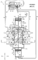
- FIG. 3 is a vertical cross-sectional view showing a first communication state (during a cooling operation) of the first embodiment of the flow path switching valve (hexagonal switching valve) according to the present invention.
- FIG. 3 is a vertical cross-sectional view showing a second communication state (during heating operation) of the first embodiment of the flow path switching valve (hexagonal switching valve) according to the present invention.
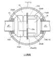
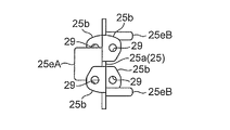
- FIG. 2 is an enlarged vertical cross-sectional view of an essential part showing an enlarged essential part of the six-way switching valve shown in FIG. 1. Sectional drawing which follows the OU arrow line of FIG. The perspective view which shows the main valve body and connection body of 1st Embodiment of the flow-path switching valve (hexagonal switching valve) which concerns on this invention.
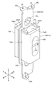
- FIG. 3 is a vertical cross-sectional view showing the connection body of the first embodiment of the flow path switching valve (hexagonal switching valve) according to the present invention.
- FIG. 3 is a left side view showing the connection body of the first embodiment of the flow path switching valve (hexagonal switching valve) according to the present invention.
- the top view which shows the connection body of 1st Embodiment of the flow-path switching valve (hexagonal switching valve) which concerns on this invention.
- the longitudinal cross-sectional view which expands and shows the 1st communicating state (at the time of cooling operation) (at the time of energization OFF) of the four-way pilot valve used for the flow-path switching valve (6 way switching valve) which concerns on this invention.
- the longitudinal cross-sectional view which expands and shows the 2nd communicating state (at the time of heating operation) (at the time of electricity supply ON) of the four-way pilot valve used for the flow-path switching valve (6 way switching valve) which concerns on this invention.
- the longitudinal cross-sectional view which shows 2nd Embodiment (1st communicating state (at the time of cooling operation)) of the flow-path switching valve (6 way switching valve) which concerns on this invention.
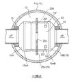
- Sectional drawing which follows the VV arrow line of FIG.
- the perspective view which shows the main valve body and connection body of 2nd Embodiment of the flow-path switching valve (hexagonal switching valve) which concerns on this invention.
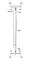
- the longitudinal cross-sectional view which shows the connection body of 2nd Embodiment of the flow-path switching valve (hexagonal switching valve) which concerns on this invention.
- the left view which shows the connection body of 2nd Embodiment of the flow-path switching valve (hexagonal switching valve) which concerns on this invention.
- the top view which shows the connection body of 2nd Embodiment of the flow-path switching valve (hexagonal switching valve) which concerns on this invention.
- the longitudinal cross-sectional view which shows 3rd Embodiment (1st communicating state (at the time of cooling operation)) of the flow-path switching valve (6 way switching valve) which concerns on this invention. Sectional drawing which follows the XX arrow line of FIG.
- the perspective view which shows the main valve body and connection body of 3rd Embodiment of the flow-path switching valve (hexagonal switching valve) which concerns on this invention.
- the longitudinal cross-sectional view which shows the connection body of 3rd Embodiment of the flow-path switching valve (hexagonal switching valve) which concerns on this invention.
- the left side view which shows the connection body of 3rd Embodiment of the flow-path switching valve (hexagonal switching valve) which concerns on this invention.
- the top view which shows the connection body of 3rd Embodiment of the flow-path switching valve (hexagonal switching valve) which concerns on this invention.
- FIG. 1 and 2 are vertical cross-sectional views showing a first embodiment of a six-way switching valve as a flow path switching valve according to the present invention.
- FIG. 1 is a first communication state (during cooling operation)
- FIG. 5 is a diagram showing a second communication state (during heating operation).
- the gaps formed between the members and the separation distances between the members are larger than the dimensions of each constituent member in order to facilitate understanding of the invention and for convenience in drawing. Or it may be drawn small.
- the six-way switching valve 1 of the illustrated embodiment is a slide type used as, for example, a six-way switching valve in a heat pump type heating and cooling system, and basically has a cylinder type six-way valve body 10 and a single solenoid type pilot valve. And a four-way pilot valve 90.
- the six ports provided in the six-way switching valve 1 of the present embodiment are designated by the same reference numerals corresponding to the ports pA to pF of the six-way switching valve described in Patent Documents 1 and 2 above. ing.
- the hexagonal valve body 10 has a tubular main valve housing 11 made of metal such as brass or stainless steel.
- a first working chamber 31, a first piston 21, a main valve chamber 12, a second piston 22, and a second working chamber 32 are sequentially arranged in the main valve housing 11 from one end side (upper end side).
- a spring-loaded packing whose outer peripheral portion is in pressure contact with the inner peripheral surface of the main valve housing 11 is attached to partition the main valve housing 11 in an airtight manner. ..
- the main valve housing 11 has a relatively large-diameter body portion 11c.
- the first piston portion 11a made of a (relatively small diameter) pipe member is placed in the central hole provided in the thick disk-shaped upper coupling lid 11d airtightly attached to the upper end opening of the body portion 11c.
- the first piston 21 is disposed in the first piston portion 11a, which is airtightly fixed by attachment or the like.
- a second piston portion formed of a pipe member (having a relatively small diameter) is provided in a central hole provided in a thick disk-shaped lower coupling lid 11e airtightly attached to a lower end opening of the body portion 11c.
- 11b is airtightly fixed by brazing or the like, and the second piston 22 is arranged in the second piston portion 11b.
- the main valve housing 11 At the upper end of (the first piston portion 11a of) the main valve housing 11 is a thick-walled disc that also functions as a stopper that prevents upward movement of the first piston 21 that defines the first working chamber 31 of variable capacity.
- the upper end side lid member 11A is airtightly fixed by brazing or the like.
- the main valve housing 11 At the lower end of (the second piston portion 11b of) the main valve housing 11 is a thick-walled disc that also functions as a stopper that prevents downward movement of the second piston 22 that defines the second working chamber 32 of variable capacity.
- the lower end side lid member 11B is airtightly fixed by brazing or the like.
- Ports p11 and p12 for introducing and discharging high-pressure fluid (refrigerant) to the first working chamber 31 and the second working chamber 32 are attached to the upper end side lid member 11A and the lower end side lid member 11B, respectively.
- the main valve housing 11 (main valve chamber 12 thereof) is provided with a total of six ports.
- a metal-made first main valve seat (valve seat) 13 whose surface (right surface) is a flat valve seat surface is formed by brazing or the like. It is airtightly fixed to (the inner circumference of) the body portion 11c of the housing 11.
- three ports (portion pB, port pA, port pF, sequentially from the upper end side), which are pipe joints extending to the left, are vertically arranged (axis O direction). It is made to open at substantially equal intervals.
- a second main valve seat (valve seat) 14 made of metal is airtightly fixed to (the inner circumference of) the body portion 11c of the main valve housing 11 by brazing or the like. ..
- three ports (pipe pC, port pD, port pE, sequentially from the upper end side), which are pipe joints extending rightward, are vertically arranged (axis O direction). It is made to open at substantially equal intervals.
- the ports pA to pF provided on the first main valve seat 13 and the second main valve seat 14 are set to have substantially the same diameter while being set to the position (opposite to the axis O). Has been done.
- both side surfaces are valve seat surfaces of the first main valve seat 13 and the second main valve seat 14.
- Sliding main valve bodies 15 each having a racetrack-shaped annular sealing surface and having a rectangular cross section are slidably opposed to each other and are movably arranged in the axis O direction (vertical direction).
- the dimension of the main valve body 15 in the left-right direction is made slightly larger than the outer diameters of the first piston portion 11a and the second piston portion 11b of the main valve housing 11.
- the main valve body 15 is made of, for example, a synthetic resin, and has a first slide valve body 15A on the first main valve seat 13 side (left side) and a second slide valve body 15B on the second main valve seat 14 side (right side). And are distributed in a state of being back-to-back.
- a first U-turn passage (communication passage) 16A having a bowl-shaped recess having a size that allows selective communication between the ports (port pB and port pA or port pA and port pF) is provided on the right side of the second slide valve body 15B (on the side opposite to the side of the first slide valve body 15A).
- a second U-turn passage (communication passage) 16B having a bowl-shaped recess having a size that allows selective communication between the individual ports (port pC and port pD, or port pD and port pE) is provided.
- a tubular portion 15b having substantially the same shape as the outer shape of the second slide valve body 15B (that is, a rectangular tubular shape) is formed on the left surface of the second slide valve body 15B (the surface facing the first slide valve body 15A). Is extended (to the left beyond the axis (center line) O). A short cylinder slightly smaller than the outer shape of the first slide valve body 15A (in other words, the outer shape of the second slide valve body 15B) on the right surface of the first slide valve body 15A (the surface facing the second slide valve body 15B). -Shaped fitting protrusion 15a is provided so as to project (to the right).
- the fitting protrusion 15a is slidably fitted into the tubular portion 15b (with the O-ring 18 sandwiched between the step portions provided therebetween), so that the first slide valve body 15A and the second slide valve body 15A
- the valve body 15B is defined in the left-right direction (each port (port pB, port pA, port pF) provided in the first main valve seat 13 in the direction perpendicular to the axis O and the second main valve seat 14).
- Some of the provided ports (port pC, port pD, port pE) face each other, that is, the direction perpendicular to the valve seat surfaces of the first main valve seat 13 and the second main valve seat 14). It is movable and can move integrally in the vertical direction (axis O direction).
- the arrangement relationship between the fitting convex portion 15a of the first slide valve body 15A and the tubular portion 15b of the second slide valve body 15B may be reversed. That is, the first slide valve element 15A is provided with a tubular portion, the second slide valve element 15B is provided with a fitting convex portion, and the first slide valve element 15A is provided with a tubular portion in which a second slide valve element 15B is fitted.
- the first slide valve body 15A and the second slide valve body 15B may be integrated with each other by fitting a portion therein.
- first slide valve body 15A the inner portion of the fitting convex portion 15a
- second slide valve body 15B the inner portion of the fitting convex portion 15a
- a slight gap is formed in the first slide valve body 15A (at the bottom of the first U-turn passage 16A), and a communication hole 16a is formed which is a lateral hole that connects the first U-turn passage 16A and the gap.
- An O-ring 18 as a seal member is interposed between the fitting convex portion 15a and the tubular portion 15b.
- a seal member such as a lip seal may be used instead of the O-ring 18.
- a portion inside the O-ring 18 including the gap is a pressure chamber 17 into which a high-pressure fluid (refrigerant) is introduced from the port (discharge-side high-pressure port) pA via the first U-turn passage 16A and the communication hole 16a.
- a high-pressure fluid refrigerant
- the pressure chamber 17 and the main valve chamber 12 are sealed by the O-ring 18 arranged between them.
- the pressure chamber 17 side (right surface side) in the first slide valve body 15A is viewed in the left-right direction (direction perpendicular to the axis O). ) Is larger than the pressure receiving area Sa on the first main valve seat 13 side (left side).
- the projected area (pressure receiving area Sb) of the surface that receives pressure is the projected area of the annular seal surface on the side of the first main valve seat 13 with respect to the plane perpendicular to the left-right direction, and the port (inside the annular seal surface)
- the first slide valve body 15A (the left surface thereof) is made larger than the projected area (pressure receiving area Sa) of the surface that receives the pressure in the right direction by the high-pressure refrigerant flowing therethrough.
- the high-pressure refrigerant is introduced into the first U-turn passage 16A through the port (discharge-side high-pressure port) pA, and a part of the high-pressure refrigerant introduced into the first U-turn passage 16A is pressurized through the communication hole 16a.
- the pressure received from (the high-pressure refrigerant of) the pressure chamber 17 (more specifically, the pressure received from (the high-pressure refrigerant of the pressure chamber 17) and the refrigerant (low-pressure refrigerant) flowing in the second U-turn passage 16B when the chamber 17 is filled) (The pressure difference from the pressure received from) causes the right surface (the annular sealing surface) of the second slide valve body 15B to be pressed against the valve seat surface of the second main valve seat 14 and receives from the pressure chamber 17 (the high pressure refrigerant thereof).
- the left surface (the annular sealing surface) of the first slide valve body 15A becomes the valve seat surface of the first main valve seat 13. It is designed to be pressed.
- a plurality of spring receiving holes 19a and 19b are formed in each of the right surface of the first slide valve body 15A and the left surface of the second slide valve body 15B (the portion facing the pressure chamber 17 in the illustrated example).
- a compression coil spring 19 for urging the first slide valve body 15A and the second slide valve body 15B in opposite directions (separation directions) is compressed in the spring receiving holes 19a and 19b (in the example shown in the figure).
- Compression coil springs 19 are mounted at two upper and lower positions between the right surface of the first slide valve body 15A and the left surface of the second slide valve body 15B).
- the left surface (the annular sealing surface) of the first slide valve body 15A is pressed against (pressed against) the valve seat surface of the first main valve seat 13, and the right surface (the annular surface of the second slide valve body 15B).
- the seal surface) is pressed against (pressed against) the valve seat surface of the second main valve seat 14.
- a reinforcing pin 15d for maintaining the shape is installed in the front-rear direction at substantially the center of the second U-turn passage 16B of the second slide valve body 15B in which the low-pressure refrigerant flows. See also).
- the pressing plate portion (central pressing plate portion) of the connecting body 25 described later is provided on the upper and lower surfaces (outer peripheral surfaces) of the first slide valve body 15A and the second slide valve body 15B constituting the main valve body 15. 25eA and the end pressing plate 25eB) are formed with recessed surfaces 15eA and 15eB (with a slight gap in the left-right direction).
- the main valve body 15 is moved in the direction of the axis O together with the first slide valve body 15A and the second slide valve body 15B, so that the port pF as shown in FIG.
- the port pB and the port pA are opened to communicate with each other through the first U-turn passage 16A of the first slide valve body 15A, and the port pE is opened and the port pC and the port pD are connected to the second U-turn of the second slide valve body 15B.
- the cooling position (upper end position) for communicating via the passage 16B and the port pB are opened and the port pA and the port pF are opened via the first U-turn passage 16A of the first slide valve body 15A.
- the port pC is opened and the heating position (lower end position) for communicating the port pD and the port pE via the second U-turn passage 16B of the second slide valve body 15B can be selectively set. ..
- the first slide valve body 15A of the main valve body 15 is located immediately above two ports (port pB and port pA or port pA and port pF) out of the three ports except during movement
- the second slide valve body 15B of the main valve body 15 is located immediately above two ports (port pC and port pD, or port pD and port pE) of the three ports except during movement
- the pressure from the pressure chamber 17 high-pressure refrigerant introduced into the pressure chamber
- the biasing force of the compression coil spring 19 cause left and right movements, respectively. It is pressed and pressed against the valve seat surfaces of the first main valve seat 13 and the second main valve seat 14.
- the first piston 21 and the second piston 22 are connected by a connecting body 25 so that they can move integrally.
- a state in which the first slide valve body 15A and the second slide valve body 15B of the main valve body 15 are slightly slidable in the left-right direction and are prevented from moving in the up-down direction and the front-back direction on the connecting body 25. It is supported by being fitted with.
- the connecting body 25 is composed of a single plate member having a vertically long and substantially rectangular shape manufactured by, for example, press molding, and basically, the left and right sides on the axis O (center line) of the main valve housing 11. They are arranged so as to be orthogonal to the direction (in other words, parallel to the valve seat surfaces of the first main valve seat 13 and the second main valve seat 14).
- the connecting body 25 includes the first main valve seat 13 and the second main valve on the axis O of the main valve housing 11. It has a flat plate portion 25a arranged in parallel with the valve seat surface of the seat 14.
- the first slide valve body 15A and the second slide valve body 15B of the main valve body 15 are slidable in the left-right direction at the center of the flat plate portion 25a.
- a rectangular opening 25d to be fitted is formed.
- the central pressing plate portion 25eA having a relatively wide width is formed so as to extend toward the annular seal surface side of the seat 13 that slides on the valve seat surface (flat plate portion). 25a, and is provided continuously from both ends thereof (in the front-rear direction) to the right side (in other words, on the second slide valve body 15B, the annular seal surface side that slides on the valve seat surface of the second main valve seat 14).
- a pair of (a total of four vertically) end pressing plates 25eB having a relatively narrow width that is, a rectangular shape having a narrow width in the front-rear direction) so as to extend toward each other (integrated with the flat plate 25a). It is lined up.
- the central portion pressing plate portion 25eA and the end portion pressing plate portion 25eB are configured such that the one plate material is bent (in other words, cut and raised) in a substantially vertical direction (90°) from the flat plate portion 25a.
- the central pressing plate portion 25eA exceeds the recessed surface 15eB formed in the upper and lower surfaces of the second slide valve body 15B. It extends to a recessed surface 15eA formed on the upper and lower surfaces of the 1-slide valve body 15A.
- the substantially left half portion of the central portion pressing plate portion 25eA is brought into contact (pressing) with the recessed surface 15eA of the first slide valve body 15A.
- the substantially right half portion of the central portion pressing plate portion 25eA and the end portion pressing plate portion 25eB are adapted to abut (press) on the recessed surface 15eB of the second slide valve body 15B.
- a circular opening 25c (having substantially the same diameter as the ports pF and pE) is formed at a position substantially right next to the lower port pE, and when the main valve body 15 takes the heating position (lower end position), A circular opening 25c (having substantially the same diameter as the ports pB and pC) is formed at a position substantially right next to the upper port pB of the first main valve seat 13 and the upper port pC of the second main valve seat 14.
- mounting leg portions 25b formed by being bent substantially vertically (at 90°) in the front-rear direction are provided.
- the insertion hole 29 of the present embodiment has a female screw formed on its inner peripheral portion and is configured to be screwed with the male screw of the bolt 30.
- the connecting body 25 is rotationally symmetrical about the rotation axis perpendicular to the valve seat surfaces of the first main valve seat 13 and the second main valve seat 14 in order to suppress the occurrence of misassembly. Is formed on.
- the first slide valve body 15A and the second slide valve body 15B of the main valve body 15 fitted and supported by the connecting body 25 are reciprocally moved by the first and second pistons 21 and 22.
- the central portion pressing plate portion 25eA and the pair of end portion pressing plate portions 25eB provided in (the upper and lower end edges of) the rectangular opening 25d of the connecting body 25 are pushed to cool and heat the air conditioner (upper end position). It is designed to move back and forth between the position (lower end position).
- the central pressing plate portion 25eA and the pair of end pressing plate portions 25eB described above are used to position the first slide valve body 15A and the second slide valve body 15B of the main valve body 15 at positions close to the annular seal surface (in other words, Then, the portions of the first main valve seat 13 and the second main valve seat 14 near the valve seat surface) are pushed.
- the main valve body 15 arranged in the main valve housing 11 When the main valve body 15 arranged in the main valve housing 11 is in the heating position (lower end position) (second communication state as shown in FIG. 2), the main valve body 15 is moved to the first position via the four-way pilot valve 90 described later.
- the second working chamber 32 When the second working chamber 32 is communicated with the port pA which is the discharge side high pressure port and the first working chamber 31 is communicated with the port pD which is the suction side low pressure port, a high pressure refrigerant is introduced into the second working chamber 32. At the same time, the high-pressure refrigerant is discharged from the first working chamber 31.
- the pressure of the second working chamber 32 on the other end side (lower end side) of the main valve chamber 12 becomes higher than the pressure of the first working chamber 31 on one end side (upper end side) of the main valve chamber 12, as shown in FIG.
- the first and second pistons 21 and 22 and the main valve body 15 move upward, the first piston 21 is abutted and locked to the upper end side lid member 11A, and the main valve body 15 moves to the cooling position (upper end).
- Position) first communication state as shown in FIG. 1).
- the first working chamber 31 When the main valve body 15 is in the cooling position (upper end position) (first communication state as shown in FIG. 1), the first working chamber 31 is connected to the discharge-side high pressure port via the four-way pilot valve 90 described later.
- a high pressure refrigerant When communicating with a certain port pA and communicating the second working chamber 32 with the port pD which is the suction side low pressure port, a high pressure refrigerant is introduced into the first working chamber 31 and a high pressure refrigerant from the second working chamber 32 is introduced. The refrigerant is discharged. Therefore, the pressure of the first working chamber 31 on one end side (upper end side) of the main valve chamber 12 becomes higher than the pressure of the second working chamber 32 on the other end side (lower end side) of the main valve chamber 12, as shown in FIG.
- the ports pA and pF are made to communicate (via the first U-turn passage 16A), the ports pE and pD are made to communicate (via the second U-turn passage 16B), and the ports pC and pB are made to communicate. Since and are communicated with each other (via the main valve chamber 12), the heating operation is performed in the heat pump cooling and heating system.
- FIGS. 7A and 7B The structure itself of the four-way pilot valve 90 as a pilot valve is well known, and as shown in the enlarged view of FIGS. 7A and 7B, the electromagnetic coil 91 is provided on the outer periphery of the base end side (left end side). It has a valve case 92 which is a cylindrical straight pipe that is fitted and fixed. In the valve case 92, a suction element 95, a compression coil spring 96, and a plunger 97 are sequentially arranged in series from the base end side.
- valve case 92 The left end of the valve case 92 is hermetically joined to the flange-shaped portion (peripheral terrace) of the suction element 95 by welding or the like.
- the attractor 95 is fastened and fixed by a bolt 92B to a cover case 91A that covers the outer circumference of the electromagnetic coil 91 for energizing and exciting.
- a lid member 98 with a filter having a thin tube insertion port (high pressure introduction port a) for introducing high pressure refrigerant is hermetically attached by welding, brazing, caulking or the like.
- a region surrounded by the lid member 98, the plunger 97, and the valve case 92 is a valve chamber 99.
- High-pressure refrigerant is introduced into the valve chamber 99 from the port (discharge-side high-pressure port) pA via the high-pressure thin tube #a that is hermetically inserted into the thin-tube insertion port (high-pressure introduction port a) of the lid member 98. It is supposed to be done.
- a valve seat 93 having an inner end surface that is a flat valve seat surface is hermetically joined by brazing or the like between the plunger 97 and the lid member 98 in the valve case 92.
- a port b and a port that are sequentially connected from the tip end side (right end side) to the first working chamber 31 of the hexagonal valve body 10 via the thin tube #b.
- a port c connected to pD via the thin tube #c and a port d connected to the second working chamber 32 via the thin tube #d are arranged in the longitudinal direction (left-right direction) of the valve case 92. Are opened side by side at a predetermined interval.
- the plunger 97 arranged to face the suction element 95 is basically cylindrical and is slidably arranged in the valve case 92 in the axial direction (direction along the center line L of the valve case 92). ..
- a valve body holder 94A that holds the valve body 94 slidably in the thickness direction at its free end side has its base end portion together with a mounting member 94B. It is attached and fixed by press fitting, caulking, etc.
- a leaf spring 94C for urging the valve body 94 in a direction (thickness direction) for pressing the valve body 94 against the valve seat 93 is attached to the valve body holder 94A.
- the valve body 94 is in contact with the valve seat surface of the valve seat 93 in order to switch the communication state between the ports b, c, d opened on the valve seat surface of the valve seat 93.
- the valve seat surface slides as the plunger 97 moves in the left-right direction.
- valve body 94 has a size such that the adjacent ports bc and cd of the three ports b to d opened on the valve seat surface of the valve seat 93 can be selectively communicated with each other.
- the recessed portion 94a is provided.
- the compression coil spring 96 is compressed between the suction element 95 and the plunger 97 to urge the plunger 97 in the direction of separating the plunger 97 from the suction element 95 (rightward in the figure).
- the valve seat 93 (the left end portion thereof) serves as a stopper that prevents the plunger 97 from moving to the right. Needless to say, other configurations can be adopted as the configuration of this stopper.
- the above-mentioned four-way pilot valve 90 is attached to an appropriate location such as the back side of the six-way valve body 10 via the attachment tool 92A.
- the high-pressure fluid flowing into the port (discharge-side high-pressure port) pA is introduced into the second working chamber 32 through the high-pressure thin tube #a ⁇ valve chamber 99 ⁇ port d ⁇ thin tube #d ⁇ port p12, and The high-pressure fluid in the working chamber 31 flows to the port p11 ⁇ the thin tube #b ⁇ the port b ⁇ the recess 94a ⁇ the port c ⁇ the thin tube #c ⁇ the port (suction side low-pressure port) pD and is discharged.
- the plunger 97 is attracted by the suction element 95 to the position where its left end contacts the suction element 95 (compression). Attracted (against the bias of the coil spring 96). At this time, the valve body 94 is located on the port c and the port d, and the recess 94a allows the port c and the port d to communicate with each other and the port b and the valve chamber 99 to communicate with each other.
- the high-pressure fluid flowing into the port (discharge-side high-pressure port) pA is introduced into the first working chamber 31 through the high-pressure thin tube #a ⁇ valve chamber 99 ⁇ port b ⁇ thin tube #b ⁇ port p11, and the second The high-pressure fluid in the working chamber 32 flows to the port p12 ⁇ capillary tube #d ⁇ port d ⁇ recess 94a ⁇ port c ⁇ capillary tube #c ⁇ port (suction side low-pressure port) pD and is discharged.
- the main valve body 15 of the six-way valve body 10 shifts from the heating position (second communication state) to the cooling position (first communication state), and the flow path as described above is set.
- the main valve body 15 of the six-way valve body 10 is moved from the cooling position (first communication state) to the heating position (second communication state), and the above-mentioned operation is performed.
- the flow path is switched as described above.
- the six-way switching valve 1 of the present embodiment by energizing the electromagnetic four-way pilot valve 90 by turning it ON/OFF, the high-pressure fluid (the port pA, which is a high-pressure portion, flowing in the six-way switching valve 1 is By moving the main valve body 15 constituting the six-way valve body 10 in the main valve chamber 12 by utilizing the differential pressure between the flowing fluid) and the low pressure fluid (the fluid flowing through the port pD which is the low pressure portion), the main valve The communication state between the six ports provided in total in the housing 11 is switched, and in the heat pump type heating and cooling system, switching from heating operation to cooling operation and switching from cooling operation to heating operation can be performed.
- the main valve body 15 is moved in the main valve chamber 12 as the first and second pistons 21 and 22 reciprocate.
- the first and second main valve seats 13 and 14 is composed of a single plate member having a flat plate portion 25a arranged in parallel with the valve seat surfaces of the main valve body 15 and An annular shape that fits and supports the valve seats and slides on the valve seat surfaces of the first and second main valve seats 13 and 14 in the pair of first and second slide valve bodies 15A and 15B that form the main valve body 15.
- the main valve element 15 is connected to the first and second pistons via a pressing plate portion (a central pressing plate portion 25eA and an end pressing plate portion 25eB integrally formed with the flat plate portion 25a) extending toward the sealing surface side. It is adapted to be pushed along with the reciprocating movement of 21 and 22. Therefore, for example, as compared with a conventional flow path switching valve in which the connecting body is made of a single plate material that is arranged parallel to the valve seat surface of the main valve seat on the center line (axis) of the main valve housing, On the seal surface of the main valve body 15 (both annular seal surfaces of the two first and second slide valve bodies 15A and 15B) when switching the flow path with a simple configuration in which the body 25 is slightly modified. It is possible to push a close position, it is possible to suppress the occurrence of the stick-slip phenomenon, and therefore it is possible to effectively suppress the generation of abnormal noise and the wear of the seal surface of the main valve body 15.
- a pressing plate portion a central pressing plate portion 25eA and an
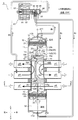
- FIG. 8 is a vertical cross-sectional view showing a second embodiment of a six-way switching valve as a flow path switching valve according to the present invention.
- FIG. 9 is a sectional view taken along the line VV of FIG.
- the six-way switching valve 2 of the illustrated second embodiment is different from the above-described six-way switching valve 1 of the first embodiment mainly in the configuration of the connecting portion between the piston and the main valve body, and other configurations are omitted. Is the same. Therefore, parts corresponding to the respective parts of the six-way switching valve 1 are given common reference numerals, and redundant description will be omitted. In the following, different points will be mainly described.
- the six-way switching valve 2 of the illustrated embodiment is, like the six-way switching valve 1 of the first embodiment, a slide type used as, for example, a six-way switching valve in a heat pump type cooling and heating system.
- the central pressing plate portion 25eA and the end pressing plate portion 25eB at the edge portion of the rectangular opening 25d formed in (the flat plate portion 25a of) the connecting body 25 are omitted ( (See also FIGS. 10 and 11A-11C).
- the first slide valve body 15A and the second slide valve body 15B constituting the main valve body 15 are formed on the upper and lower surfaces (the recessed surfaces 15eA and 15eB formed on the upper surface) by, for example, press molding.
- a plate material (for example, the same material as the connecting body 25) having a substantially rectangular shape and having higher rigidity than (the first and second slide valve bodies 15A and 15B of, the main valve body 15) described above.
- a pressing plate (pressing plate portion) 20 made of a flat plate is fixedly arranged by press fitting, welding, insert molding, or the like.
- the pressing plate 20 has an outer shape that covers almost all of the recessed surfaces 15eA and 15eB formed on the upper and lower surfaces of the first slide valve body 15A and the second slide valve body 15B constituting the main valve body 15. It has (in particular, see FIG. 9), and is arranged so as to be along the recessed surfaces 15eA, 15eB and to be perpendicular to the axis (center line) O of the main valve housing 11.
- the pressing plate 20 has a right end portion that extends toward the right side (in other words, an annular seal surface side that slides on the valve seat surface of the second main valve seat 14 in the second slide valve body 15B), and has a right end portion that is the second slide valve.
- the upper surface or the lower surface of the body 15B (the recessed surface 15eB formed on the lower surface) is fixed and the left side (in other words, the annular seal surface side that slides on the valve seat surface of the first main valve seat 13 in the first slide valve body 15A).
- the left end portion extending toward (up to the upper surface or the lower surface of the first slide valve body 15A (recessed surface 15eA formed in) is slidable without being fixed).
- the left and right movements (relative movements) of the bodies 15A and 15B are not restricted.
- the left portion of the pressing plate 20 is adapted to abut (press) against the recessed surface 15eA of the first slide valve body 15A.
- the right side portion from the central portion of the pressing plate 20 is adapted to abut (press) against the recessed surface 15eB of the second slide valve body 15B.
- the first slide valve body 15A and the second slide valve body 15B of the main valve body 15 fitted and supported by the connecting body 25 are reciprocally moved by the first and second pistons 21 and 22. Along with this, it is pushed by the rectangular opening 25d portion of the connecting body 25 so as to move back and forth between the cooling position (upper end position) and the heating position (lower end position).
- the rectangular opening 25d portion of the connecting body 25 comes into contact with the pressing plate 20 (substantially the central portion thereof) fixed to the outer peripheral surface of the main valve body 15 so that the first main valve body 15 has the first opening.
- the slide valve body 15A and the second slide valve body 15B are pushed.
- the pressing plate 20 is attached to the positioning projections 15f (two in front and back) provided on the recessed surface 15eB of the upper surface or the lower surface on the second slide valve body 15B side, for example.
- the fitting round holes 20f (two at the front and rear) provided in the vicinity of the right end portion of the are fitted and fixed (in particular, see FIGS. 9 and 10).
- the connecting body 25 for moving the main valve body 15 in the main valve chamber 12 with the reciprocating movement of the first and second pistons 21, 22 Is composed of a single plate member having a flat plate portion 25a arranged in parallel with the valve seat surfaces of the first and second main valve seats 13 and 14, and the flat plate portion 25a is fitted with the main valve body 15.
- the main valve body 15 is pushed along with the reciprocating movement of the first and second pistons 21 and 22 via the pushing plate portion (the pushing plate 20 fixed to the outer peripheral surface of the main valve body 15) extending toward It is supposed to do. Therefore, for example, compared with a conventional flow path switching valve in which the connecting body is made of a single plate material that is arranged parallel to the valve seat surface of the main valve seat on the center line (axis line) of the main valve housing, Sealing surface of the main valve body 15 (both annular sealing surfaces of the two first and second slide valve bodies 15A and 15B) when switching the flow path with a simple configuration in which the valve body 15 is slightly modified. It is possible to press a position close to, and it is possible to suppress the occurrence of the stick-slip phenomenon, and thus it is possible to effectively suppress the occurrence of abnormal noise and the wear of the seal surface of the main valve body 15.
- the area (pressing area) for pressing the main valve body 15 (the first and second slide valve bodies 15A and 15B) Since a large value can be obtained, it is possible to further reduce the stress applied to (the first and second slide valve elements 15A, 15B of) the main valve body 15.
- FIG. 12 is a vertical cross-sectional view showing a third embodiment of a six-way switching valve as a flow path switching valve according to the present invention.
- 13 is a sectional view taken along the line XX of FIG.
- the six-way switching valve 3 according to the illustrated third embodiment is slightly different from the above-described six-way switching valve 2 according to the second embodiment mainly in the configuration of the main valve housing, the main valve body, the coupling body, and the like.
- the configuration is almost the same. Therefore, the portions corresponding to the respective portions of the six-way switching valve 2 are given the common reference numerals, and the duplicate description will be omitted. In the following, the different points will be mainly described.
- the six-way switching valve 3 of the illustrated embodiment is, like the six-way switching valve 2 of the second embodiment, for example, a slide type used as a six-way switching valve in a heat pump type cooling and heating system. It is smaller and lighter than the valve 2.
- the body portion 11c of the main valve housing 11 is formed to have the same diameter as the first and second piston portions 11a and 11b, and the first and second piston portions 11a and 11b and the body portion 11c are integrated. (As one component).
- the main valve body 15 (in particular, the first slide valve body 15A on the high pressure side thereof) is formed relatively thin (specifically, the thickness in the left-right direction is relatively thin), and the first slide valve body 15A is formed.
- the recessed surface 15eA on the upper and lower surfaces and the communication hole 16a in the first slide valve body 15A are omitted.
- four compression coil springs for urging the first slide valve element 15A and the second slide valve element 15B in opposite directions are arranged in this example as well. Has been done.
- the right surface (the annular sealing surface) of the second slide valve body 15B is pressed against the valve seat surface of the second main valve seat 14, and the pressure chamber 17 (the high-pressure refrigerant of the pressure chamber 17).
- the left surface (the annular sealing surface) of the first slide valve body 15A is a valve of the first main valve seat 13 It is designed to be pressed against the seat surface.
- the pressing plate 20 is formed on the upper and lower surfaces of the second slide valve body 15B constituting the main valve body 15.
- the recessed surface 15eB has an outer shape that covers almost the entire surface of the recessed surface 15eB (see in particular FIG. 13) and is distributed along the recessed surface 15eB so that only the recessed surface 15eB can be contacted (pressed). It has become.
- the rectangular opening 25d portion of the connecting body 25 comes into contact with the pressing plate 20 (substantially the central portion thereof) fixed to the outer peripheral surface of the main valve body 15, whereby the first opening of the main valve body 15 is reduced.
- the slide valve body 15A and the second slide valve body 15B are pushed, but the first slide valve body 15A is pushed (integrated with the second slide valve body 15B) via the second slide valve body 15B. It is like this.
- the pressing plate 20 is provided on (the outer edge of) the pressing plate 20 in the positioning projection 15g provided on the recessed surface 15eB of the upper surface or the lower surface on the second slide valve body 15B side, for example.
- the fitting notch 20g is fitted and fixed (see especially FIGS. 13 and 14).
- the vertical length (the length in the direction of the axis O) of the connecting body 25 is shorter than that of the hexagonal switching valve 2 of the second embodiment, and is formed on (the flat plate portion 25a of) the connecting body 25.
- the rectangular opening 25d and the circular openings 25c formed above and below the rectangular opening 25d are formed to be continuous (see also FIG. 14 and FIGS. 15A to 15C). Therefore, in this example, only the front and rear portions of the rectangular opening 25d portion of the connecting body 25 come into contact with the pressing plate 20 (approximately the central portion thereof) fixed to the outer peripheral surface of the main valve body 15, The first slide valve body 15A and the second slide valve body 15B of the main valve body 15 are pushed.
- the connecting body 25 for moving the main valve body 15 in the main valve chamber 12 with the reciprocating movement of the first and second pistons 21, 22 Is composed of a single plate member having a flat plate portion 25a arranged in parallel with the valve seat surfaces of the first and second main valve seats 13 and 14, and the flat plate portion 25a is fitted with the main valve body 15.
- first and second slide valve bodies 15A and 15B that constitute the main valve body 15 on the annular seal surface side that slides on the valve seat surfaces of the first and second main valve seats 13 and 14.
- the main valve body 15 is pushed along with the reciprocating movement of the first and second pistons 21 and 22 via the pushing plate portion (the pushing plate 20 fixed to the outer peripheral surface of the main valve body 15) extending toward As a result, the same operational effects as those of the hexagonal switching valve 2 in the second embodiment described above can be obtained.
- the six-way switching valves 1 to 3 of the first to third embodiments have been described by exemplifying the six-way switching valve in the heat pump type cooling and heating system.
- the number and position of the ports provided in (the main valve chamber 12 of) the main valve housing 11, the configuration and shape of the main valve housing 11, the main valve arranged in (the main valve chamber 12 of) the main valve housing 11 Of course, the configuration, shape, and the like of the body 15 are not limited to the illustrated example.
- the configuration in which the four-way pilot valve 90 is used to drive the main valve body 15 in the main valve chamber 12 has been described.
- a motor may be used to drive the main valve body 15 in the main valve chamber 12.
- the six-way switching valves 1 to 3 of the first to third embodiments can be incorporated not only in the heat pump type cooling and heating system, but also in other systems, devices, and devices.
Landscapes
- Engineering & Computer Science (AREA)
- General Engineering & Computer Science (AREA)
- Mechanical Engineering (AREA)
- Physics & Mathematics (AREA)
- Thermal Sciences (AREA)
- Multiple-Way Valves (AREA)
- Compression-Type Refrigeration Machines With Reversible Cycles (AREA)
Priority Applications (1)
| Application Number | Priority Date | Filing Date | Title |
|---|---|---|---|
| EP19901412.7A EP3904737A4 (en) | 2018-12-25 | 2019-11-08 | FLOWWAY SWITCHING VALVE |
Applications Claiming Priority (2)
| Application Number | Priority Date | Filing Date | Title |
|---|---|---|---|
| JP2018241010A JP7175499B2 (ja) | 2018-12-25 | 2018-12-25 | 流路切換弁 |
| JP2018-241010 | 2018-12-25 |
Publications (1)
| Publication Number | Publication Date |
|---|---|
| WO2020137191A1 true WO2020137191A1 (ja) | 2020-07-02 |
Family
ID=71129336
Family Applications (1)
| Application Number | Title | Priority Date | Filing Date |
|---|---|---|---|
| PCT/JP2019/043942 Ceased WO2020137191A1 (ja) | 2018-12-25 | 2019-11-08 | 流路切換弁 |
Country Status (3)
| Country | Link |
|---|---|
| EP (1) | EP3904737A4 (https=) |
| JP (1) | JP7175499B2 (https=) |
| WO (1) | WO2020137191A1 (https=) |
Cited By (1)
| Publication number | Priority date | Publication date | Assignee | Title |
|---|---|---|---|---|
| CN112727828A (zh) * | 2020-12-29 | 2021-04-30 | 中国船舶重工集团长江科技有限公司 | 双通道气道换向装置 |
Families Citing this family (2)
| Publication number | Priority date | Publication date | Assignee | Title |
|---|---|---|---|---|
| WO2024135176A1 (ja) * | 2022-12-20 | 2024-06-27 | マレリ株式会社 | 流路切換弁 |
| JP2024148807A (ja) * | 2023-04-06 | 2024-10-18 | マレリ株式会社 | 流路切換弁 |
Citations (6)
| Publication number | Priority date | Publication date | Assignee | Title |
|---|---|---|---|---|
| JPH08170864A (ja) | 1994-12-19 | 1996-07-02 | Sanyo Electric Co Ltd | ヒートポンプ空調装置及び除霜方法 |
| JP2004245427A (ja) * | 2003-02-10 | 2004-09-02 | Fuji Koki Corp | 流路切換弁 |
| CN104421459A (zh) * | 2013-09-03 | 2015-03-18 | 浙江盾安禾田金属有限公司 | 三通阀 |
| JP2016114133A (ja) * | 2014-12-12 | 2016-06-23 | 株式会社不二工機 | 流路切換弁 |
| JP2017002979A (ja) * | 2015-06-09 | 2017-01-05 | 株式会社鷺宮製作所 | スライド式切換弁及び冷凍サイクルシステム |
| JP2018044666A (ja) | 2016-09-12 | 2018-03-22 | 株式会社不二工機 | 六方切換弁 |
Family Cites Families (1)
| Publication number | Priority date | Publication date | Assignee | Title |
|---|---|---|---|---|
| JP5080612B2 (ja) * | 2010-05-17 | 2012-11-21 | 株式会社鷺宮製作所 | 流路切換弁 |
-
2018
- 2018-12-25 JP JP2018241010A patent/JP7175499B2/ja active Active
-
2019
- 2019-11-08 WO PCT/JP2019/043942 patent/WO2020137191A1/ja not_active Ceased
- 2019-11-08 EP EP19901412.7A patent/EP3904737A4/en active Pending
Patent Citations (6)
| Publication number | Priority date | Publication date | Assignee | Title |
|---|---|---|---|---|
| JPH08170864A (ja) | 1994-12-19 | 1996-07-02 | Sanyo Electric Co Ltd | ヒートポンプ空調装置及び除霜方法 |
| JP2004245427A (ja) * | 2003-02-10 | 2004-09-02 | Fuji Koki Corp | 流路切換弁 |
| CN104421459A (zh) * | 2013-09-03 | 2015-03-18 | 浙江盾安禾田金属有限公司 | 三通阀 |
| JP2016114133A (ja) * | 2014-12-12 | 2016-06-23 | 株式会社不二工機 | 流路切換弁 |
| JP2017002979A (ja) * | 2015-06-09 | 2017-01-05 | 株式会社鷺宮製作所 | スライド式切換弁及び冷凍サイクルシステム |
| JP2018044666A (ja) | 2016-09-12 | 2018-03-22 | 株式会社不二工機 | 六方切換弁 |
Non-Patent Citations (1)
| Title |
|---|
| See also references of EP3904737A4 |
Cited By (1)
| Publication number | Priority date | Publication date | Assignee | Title |
|---|---|---|---|---|
| CN112727828A (zh) * | 2020-12-29 | 2021-04-30 | 中国船舶重工集团长江科技有限公司 | 双通道气道换向装置 |
Also Published As
| Publication number | Publication date |
|---|---|
| EP3904737A1 (en) | 2021-11-03 |
| EP3904737A4 (en) | 2022-09-14 |
| JP2020101256A (ja) | 2020-07-02 |
| JP7175499B2 (ja) | 2022-11-21 |
Similar Documents
| Publication | Publication Date | Title |
|---|---|---|
| JP7071757B2 (ja) | 六方切換弁 | |
| CN109578616B (zh) | 六通切换阀 | |
| CN109424764B (zh) | 流路切换阀 | |
| WO2020137191A1 (ja) | 流路切換弁 | |
| CN109578617B (zh) | 流路切换阀 | |
| CN112585384B (zh) | 流路切换阀 | |
| JP6928945B2 (ja) | 流路切換弁及びその組立方法 | |
| WO2021054065A1 (ja) | 流路切換弁 | |
| CN112585385B (zh) | 流路切换阀 | |
| JP7095914B2 (ja) | 流路切換弁 | |
| JP6999183B2 (ja) | 流路切換弁 | |
| JP7140416B2 (ja) | 流路切換弁 | |
| JP7301350B2 (ja) | 流路切換弁 | |
| JP6678227B2 (ja) | 流路切換弁 | |
| JP6893704B2 (ja) | 流路切換弁 | |
| JP6823864B2 (ja) | 六方切換弁 |
Legal Events
| Date | Code | Title | Description |
|---|---|---|---|
| 121 | Ep: the epo has been informed by wipo that ep was designated in this application |
Ref document number: 19901412 Country of ref document: EP Kind code of ref document: A1 |
|
| NENP | Non-entry into the national phase |
Ref country code: DE |
|
| ENP | Entry into the national phase |
Ref document number: 2019901412 Country of ref document: EP Effective date: 20210726 |