WO2020137191A1 - Flow path switching valve - Google Patents
Flow path switching valve Download PDFInfo
- Publication number
- WO2020137191A1 WO2020137191A1 PCT/JP2019/043942 JP2019043942W WO2020137191A1 WO 2020137191 A1 WO2020137191 A1 WO 2020137191A1 JP 2019043942 W JP2019043942 W JP 2019043942W WO 2020137191 A1 WO2020137191 A1 WO 2020137191A1
- Authority
- WO
- WIPO (PCT)
- Prior art keywords
- main valve
- valve body
- plate portion
- flow path
- pressing plate
- Prior art date
Links
Images


Classifications
-
- F—MECHANICAL ENGINEERING; LIGHTING; HEATING; WEAPONS; BLASTING
- F16—ENGINEERING ELEMENTS AND UNITS; GENERAL MEASURES FOR PRODUCING AND MAINTAINING EFFECTIVE FUNCTIONING OF MACHINES OR INSTALLATIONS; THERMAL INSULATION IN GENERAL
- F16K—VALVES; TAPS; COCKS; ACTUATING-FLOATS; DEVICES FOR VENTING OR AERATING
- F16K11/00—Multiple-way valves, e.g. mixing valves; Pipe fittings incorporating such valves
- F16K11/02—Multiple-way valves, e.g. mixing valves; Pipe fittings incorporating such valves with all movable sealing faces moving as one unit
- F16K11/06—Multiple-way valves, e.g. mixing valves; Pipe fittings incorporating such valves with all movable sealing faces moving as one unit comprising only sliding valves, i.e. sliding closure elements
- F16K11/065—Multiple-way valves, e.g. mixing valves; Pipe fittings incorporating such valves with all movable sealing faces moving as one unit comprising only sliding valves, i.e. sliding closure elements with linearly sliding closure members
- F16K11/0655—Multiple-way valves, e.g. mixing valves; Pipe fittings incorporating such valves with all movable sealing faces moving as one unit comprising only sliding valves, i.e. sliding closure elements with linearly sliding closure members with flat slides
-
- F—MECHANICAL ENGINEERING; LIGHTING; HEATING; WEAPONS; BLASTING
- F16—ENGINEERING ELEMENTS AND UNITS; GENERAL MEASURES FOR PRODUCING AND MAINTAINING EFFECTIVE FUNCTIONING OF MACHINES OR INSTALLATIONS; THERMAL INSULATION IN GENERAL
- F16K—VALVES; TAPS; COCKS; ACTUATING-FLOATS; DEVICES FOR VENTING OR AERATING
- F16K31/00—Actuating devices; Operating means; Releasing devices
- F16K31/12—Actuating devices; Operating means; Releasing devices actuated by fluid
- F16K31/122—Actuating devices; Operating means; Releasing devices actuated by fluid the fluid acting on a piston
- F16K31/1225—Actuating devices; Operating means; Releasing devices actuated by fluid the fluid acting on a piston with a plurality of pistons
-
- F—MECHANICAL ENGINEERING; LIGHTING; HEATING; WEAPONS; BLASTING
- F16—ENGINEERING ELEMENTS AND UNITS; GENERAL MEASURES FOR PRODUCING AND MAINTAINING EFFECTIVE FUNCTIONING OF MACHINES OR INSTALLATIONS; THERMAL INSULATION IN GENERAL
- F16K—VALVES; TAPS; COCKS; ACTUATING-FLOATS; DEVICES FOR VENTING OR AERATING
- F16K31/00—Actuating devices; Operating means; Releasing devices
- F16K31/12—Actuating devices; Operating means; Releasing devices actuated by fluid
- F16K31/122—Actuating devices; Operating means; Releasing devices actuated by fluid the fluid acting on a piston
- F16K31/124—Actuating devices; Operating means; Releasing devices actuated by fluid the fluid acting on a piston servo actuated
-
- F—MECHANICAL ENGINEERING; LIGHTING; HEATING; WEAPONS; BLASTING
- F25—REFRIGERATION OR COOLING; COMBINED HEATING AND REFRIGERATION SYSTEMS; HEAT PUMP SYSTEMS; MANUFACTURE OR STORAGE OF ICE; LIQUEFACTION SOLIDIFICATION OF GASES
- F25B—REFRIGERATION MACHINES, PLANTS OR SYSTEMS; COMBINED HEATING AND REFRIGERATION SYSTEMS; HEAT PUMP SYSTEMS
- F25B13/00—Compression machines, plants or systems, with reversible cycle
-
- F—MECHANICAL ENGINEERING; LIGHTING; HEATING; WEAPONS; BLASTING
- F25—REFRIGERATION OR COOLING; COMBINED HEATING AND REFRIGERATION SYSTEMS; HEAT PUMP SYSTEMS; MANUFACTURE OR STORAGE OF ICE; LIQUEFACTION SOLIDIFICATION OF GASES
- F25B—REFRIGERATION MACHINES, PLANTS OR SYSTEMS; COMBINED HEATING AND REFRIGERATION SYSTEMS; HEAT PUMP SYSTEMS
- F25B2313/00—Compression machines, plants or systems with reversible cycle not otherwise provided for
- F25B2313/027—Compression machines, plants or systems with reversible cycle not otherwise provided for characterised by the reversing means
- F25B2313/0276—Compression machines, plants or systems with reversible cycle not otherwise provided for characterised by the reversing means using six-way valves
Definitions
- the present invention relates to a flow path switching valve that switches a flow path by moving a valve element, and for example, relates to a flow path switching valve suitable for performing flow path switching in a heat pump type cooling and heating system or the like.
- a heat pump type air conditioning system for a room air conditioner, a car air conditioner, etc. includes a compressor, an outdoor heat exchanger, an indoor heat exchanger, an expansion valve, etc., and a flow path switching valve as a flow path (flow direction) switching means.
- a four-way switching valve or a six-way switching valve is provided, and the operation mode (cooling operation and heating operation) is switched by the flow path switching valve.
- This slide type flow path switching valve (hexagonal switching valve) has a valve body (main valve housing) that incorporates a slide type main valve body and an electromagnetic pilot valve (four-way pilot valve). , A plurality of ports (six ports pA to pF) are provided, and a slide-type main valve element is arranged so as to be slidable in the left-right direction.
- On the left and right sides of the slide type main valve body in the main valve housing there are a pair of left and right piston type packings connected to the compressor discharge side and the compressor suction side via pilot valves, respectively.
- pilot valve selectively introduces and discharges high-pressure fluid (refrigerant) into the two working chambers, and utilizes the pressure difference between the two working chambers.
- the flow path switching is performed by sliding the slide type main valve element in the left-right direction.
- the left and right pistons that define the two working chambers are connected by a connecting body so that they can move integrally, and the slide type main valve body is fitted or fixed to the opening formed in the connecting body. ..
- the slide-type main valve body is provided with a plurality of ports (five ports pB to pF) by the connecting body as the piston reciprocates by introducing and discharging high-pressure fluid (refrigerant) into the two working chambers. It can be slid on (the valve seat surface of) the main valve seat.
- the slide type main valve body is formed with a lumen (communication passage) of a size that allows two adjacent ports of the plurality of ports to selectively communicate with each other. By the movement of the slide-type main valve body, the plurality of ports are selectively made to communicate with each other through the inner cavity, so that the flow path switching is performed.
- Patent Document 2 in the slide type flow path switching valve (hexagonal switching valve) described in Patent Document 1, a port is provided in order to suppress valve leakage and pressure loss and improve system efficiency. It has already been proposed to modify the arrangement and configuration of the main valve seat and the slide type main valve body.
- the predetermined position of the pressing portion when performing the flow path switching, it is necessary to move the slide type main valve element by pushing a predetermined position of the slide type main valve element with the connecting body.
- the predetermined position of the pressing portion if the predetermined position of the pressing portion is too far from the sealing surface of the sliding main valve body (sliding surface of the main valve seat with the valve seat surface), the stick-slip phenomenon easily occurs and abnormal noise occurs.
- the sealing surface of the slide type main valve body is easily worn. Therefore, the predetermined position of the pressing portion needs to be as close as possible to the sealing surface of the slide type main valve body.
- the connecting body that connects the piston and the slide-type main valve body is basically the valve seat of the main valve seat on the center line (axis) of the main valve housing. It is made of a single plate material that is arranged so as to face the surface (in other words, is arranged parallel to the valve seat surface). Therefore, in order to push the position close to the sealing surface of the slide type main valve body with the connecting body, the dimension and shape of each component such as the slide type main valve body, the main valve housing and the main valve seat are properly redesigned. There is a need.
- a pair of slide valve elements constituting a slide-type main valve element are arranged in a state of being back-to-back in a direction perpendicular to the valve seat surface of the main valve seat.
- a U-turn passage (communication passage) for selectively communicating two adjacent ports is formed in each slide valve body. Therefore, it is difficult to push a position close to the sealing surface of each slide valve body that constitutes the slide type main valve body with the connecting body.
- the present invention has been made in view of the above circumstances, and an object thereof is to be able to push a position close to the seal surface of the main valve body when performing flow path switching with a simple configuration, and to cause a stick-slip phenomenon. It is an object of the present invention to provide a flow path switching valve capable of suppressing the occurrence of noise and suppressing the generation of abnormal noise and the wear of the seal surface of the main valve body.
- a flow path switching valve is basically a cylindrical main valve housing in which a piston and a main valve chamber are arranged, and a valve seat in which a plurality of ports are opened.
- a main valve seat having a surface, a slide type main valve body that is disposed in the main valve chamber so as to be movable in the axial direction, and is slidably abutted against the valve seat surface, and the reciprocation of the piston.
- a connecting body for moving the main valve body according to movement is provided, and by moving the main valve body through the connecting body in the main valve chamber, it is possible to switch between communicating ports, A plurality of ports are opened on opposite sides of the axis of the main valve housing, and the main valve body is provided with a pair of U-turn passages for selectively communicating the plurality of ports.
- the slide valve element is arranged in a state of being back-to-back aligned in a direction perpendicular to the valve seat surface of the main valve seat, and the connecting body is arranged parallel to the valve seat surface of the main valve seat.
- the flat plate portion is arranged on the axis of the cylindrical main valve housing.
- each of the pair of slide valve bodies is slidably fitted to the flat plate portion in a direction perpendicular to a valve seat surface of the main valve seat, and the pair of slide valve bodies Openings are formed for integrally movably moving the pistons in the axial direction as the pistons reciprocate.
- the pressing plate portion is connected to the flat plate portion.
- the pressing plate portion is continuously provided to an edge portion of the opening formed in the flat plate portion.
- the pressing plate portion includes a one-side pressing plate portion extending from the flat plate portion toward one sealing surface side of the pair of slide valve bodies, and the pair of slide valve bodies from the flat plate portion. And the other side pressing plate portion extending toward the other sealing surface side.
- the pressing plate portion is formed by bending the flat plate portion in a vertical direction.
- the pressing plate portion is formed in a direction perpendicular to the axis of the cylindrical main valve housing.
- the pressing plate portion is formed along the outer peripheral surface of the main valve body.
- the pressing plate portion is fixed to the outer peripheral surface of the main valve body.
- the pressing plate portion is composed of a flat plate fixed to the outer peripheral surface of the main valve body.
- the pressing plate portion is fixed to one of the pair of slide valve bodies of the main valve body.
- the pressing plate portion is brought into contact with both of the pair of slide valve bodies of the main valve body.
- the pressing plate portion is brought into contact with only one of the pair of slide valve bodies of the main valve body.
- the pressing plate portion is fixed along a direction perpendicular to the axis of the cylindrical main valve housing.
- the pressing plate portion is fixed along the outer peripheral surface of the main valve body.
- the pressing plate portion is fitted into a recessed surface provided on the outer peripheral surface of the main valve body.
- the pressing plate portion is made of a material having higher rigidity than the main valve body.
- the connecting body is formed so as to be rotationally symmetrical about a rotation axis perpendicular to the valve seat surface of the main valve seat.
- the connecting body for moving the main valve body in the main valve chamber with the reciprocating movement of the piston has a flat plate portion arranged parallel to the valve seat surface of the main valve seat. It consists of a single plate material, and the flat plate part fits and supports the main valve body and slides on the valve seat surface of the main valve seat in at least one of the pair of slide valve bodies forming the main valve body. The main valve body is pushed along with the reciprocating movement of the piston via the pressing plate portion extending toward the sealing surface side.
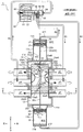
- FIG. 3 is a vertical cross-sectional view showing a first communication state (during a cooling operation) of the first embodiment of the flow path switching valve (hexagonal switching valve) according to the present invention.
- FIG. 3 is a vertical cross-sectional view showing a second communication state (during heating operation) of the first embodiment of the flow path switching valve (hexagonal switching valve) according to the present invention.
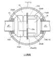
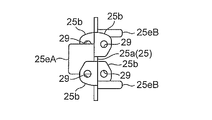
- FIG. 2 is an enlarged vertical cross-sectional view of an essential part showing an enlarged essential part of the six-way switching valve shown in FIG. 1. Sectional drawing which follows the OU arrow line of FIG. The perspective view which shows the main valve body and connection body of 1st Embodiment of the flow-path switching valve (hexagonal switching valve) which concerns on this invention.
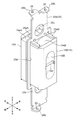
- FIG. 3 is a vertical cross-sectional view showing the connection body of the first embodiment of the flow path switching valve (hexagonal switching valve) according to the present invention.
- FIG. 3 is a left side view showing the connection body of the first embodiment of the flow path switching valve (hexagonal switching valve) according to the present invention.
- the top view which shows the connection body of 1st Embodiment of the flow-path switching valve (hexagonal switching valve) which concerns on this invention.
- the longitudinal cross-sectional view which expands and shows the 1st communicating state (at the time of cooling operation) (at the time of energization OFF) of the four-way pilot valve used for the flow-path switching valve (6 way switching valve) which concerns on this invention.
- the longitudinal cross-sectional view which expands and shows the 2nd communicating state (at the time of heating operation) (at the time of electricity supply ON) of the four-way pilot valve used for the flow-path switching valve (6 way switching valve) which concerns on this invention.
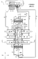
- the longitudinal cross-sectional view which shows 2nd Embodiment (1st communicating state (at the time of cooling operation)) of the flow-path switching valve (6 way switching valve) which concerns on this invention.
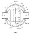
- Sectional drawing which follows the VV arrow line of FIG.
- the perspective view which shows the main valve body and connection body of 2nd Embodiment of the flow-path switching valve (hexagonal switching valve) which concerns on this invention.
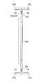
- the longitudinal cross-sectional view which shows the connection body of 2nd Embodiment of the flow-path switching valve (hexagonal switching valve) which concerns on this invention.
- the left view which shows the connection body of 2nd Embodiment of the flow-path switching valve (hexagonal switching valve) which concerns on this invention.
- the top view which shows the connection body of 2nd Embodiment of the flow-path switching valve (hexagonal switching valve) which concerns on this invention.
- the longitudinal cross-sectional view which shows 3rd Embodiment (1st communicating state (at the time of cooling operation)) of the flow-path switching valve (6 way switching valve) which concerns on this invention. Sectional drawing which follows the XX arrow line of FIG.
- the perspective view which shows the main valve body and connection body of 3rd Embodiment of the flow-path switching valve (hexagonal switching valve) which concerns on this invention.
- the longitudinal cross-sectional view which shows the connection body of 3rd Embodiment of the flow-path switching valve (hexagonal switching valve) which concerns on this invention.
- the left side view which shows the connection body of 3rd Embodiment of the flow-path switching valve (hexagonal switching valve) which concerns on this invention.
- the top view which shows the connection body of 3rd Embodiment of the flow-path switching valve (hexagonal switching valve) which concerns on this invention.
- FIG. 1 and 2 are vertical cross-sectional views showing a first embodiment of a six-way switching valve as a flow path switching valve according to the present invention.
- FIG. 1 is a first communication state (during cooling operation)
- FIG. 5 is a diagram showing a second communication state (during heating operation).
- the gaps formed between the members and the separation distances between the members are larger than the dimensions of each constituent member in order to facilitate understanding of the invention and for convenience in drawing. Or it may be drawn small.
- the six-way switching valve 1 of the illustrated embodiment is a slide type used as, for example, a six-way switching valve in a heat pump type heating and cooling system, and basically has a cylinder type six-way valve body 10 and a single solenoid type pilot valve. And a four-way pilot valve 90.
- the six ports provided in the six-way switching valve 1 of the present embodiment are designated by the same reference numerals corresponding to the ports pA to pF of the six-way switching valve described in Patent Documents 1 and 2 above. ing.
- the hexagonal valve body 10 has a tubular main valve housing 11 made of metal such as brass or stainless steel.
- a first working chamber 31, a first piston 21, a main valve chamber 12, a second piston 22, and a second working chamber 32 are sequentially arranged in the main valve housing 11 from one end side (upper end side).
- a spring-loaded packing whose outer peripheral portion is in pressure contact with the inner peripheral surface of the main valve housing 11 is attached to partition the main valve housing 11 in an airtight manner. ..
- the main valve housing 11 has a relatively large-diameter body portion 11c.
- the first piston portion 11a made of a (relatively small diameter) pipe member is placed in the central hole provided in the thick disk-shaped upper coupling lid 11d airtightly attached to the upper end opening of the body portion 11c.
- the first piston 21 is disposed in the first piston portion 11a, which is airtightly fixed by attachment or the like.
- a second piston portion formed of a pipe member (having a relatively small diameter) is provided in a central hole provided in a thick disk-shaped lower coupling lid 11e airtightly attached to a lower end opening of the body portion 11c.
- 11b is airtightly fixed by brazing or the like, and the second piston 22 is arranged in the second piston portion 11b.
- the main valve housing 11 At the upper end of (the first piston portion 11a of) the main valve housing 11 is a thick-walled disc that also functions as a stopper that prevents upward movement of the first piston 21 that defines the first working chamber 31 of variable capacity.
- the upper end side lid member 11A is airtightly fixed by brazing or the like.
- the main valve housing 11 At the lower end of (the second piston portion 11b of) the main valve housing 11 is a thick-walled disc that also functions as a stopper that prevents downward movement of the second piston 22 that defines the second working chamber 32 of variable capacity.
- the lower end side lid member 11B is airtightly fixed by brazing or the like.
- Ports p11 and p12 for introducing and discharging high-pressure fluid (refrigerant) to the first working chamber 31 and the second working chamber 32 are attached to the upper end side lid member 11A and the lower end side lid member 11B, respectively.
- the main valve housing 11 (main valve chamber 12 thereof) is provided with a total of six ports.
- a metal-made first main valve seat (valve seat) 13 whose surface (right surface) is a flat valve seat surface is formed by brazing or the like. It is airtightly fixed to (the inner circumference of) the body portion 11c of the housing 11.
- three ports (portion pB, port pA, port pF, sequentially from the upper end side), which are pipe joints extending to the left, are vertically arranged (axis O direction). It is made to open at substantially equal intervals.
- a second main valve seat (valve seat) 14 made of metal is airtightly fixed to (the inner circumference of) the body portion 11c of the main valve housing 11 by brazing or the like. ..
- three ports (pipe pC, port pD, port pE, sequentially from the upper end side), which are pipe joints extending rightward, are vertically arranged (axis O direction). It is made to open at substantially equal intervals.
- the ports pA to pF provided on the first main valve seat 13 and the second main valve seat 14 are set to have substantially the same diameter while being set to the position (opposite to the axis O). Has been done.
- both side surfaces are valve seat surfaces of the first main valve seat 13 and the second main valve seat 14.
- Sliding main valve bodies 15 each having a racetrack-shaped annular sealing surface and having a rectangular cross section are slidably opposed to each other and are movably arranged in the axis O direction (vertical direction).
- the dimension of the main valve body 15 in the left-right direction is made slightly larger than the outer diameters of the first piston portion 11a and the second piston portion 11b of the main valve housing 11.
- the main valve body 15 is made of, for example, a synthetic resin, and has a first slide valve body 15A on the first main valve seat 13 side (left side) and a second slide valve body 15B on the second main valve seat 14 side (right side). And are distributed in a state of being back-to-back.
- a first U-turn passage (communication passage) 16A having a bowl-shaped recess having a size that allows selective communication between the ports (port pB and port pA or port pA and port pF) is provided on the right side of the second slide valve body 15B (on the side opposite to the side of the first slide valve body 15A).
- a second U-turn passage (communication passage) 16B having a bowl-shaped recess having a size that allows selective communication between the individual ports (port pC and port pD, or port pD and port pE) is provided.
- a tubular portion 15b having substantially the same shape as the outer shape of the second slide valve body 15B (that is, a rectangular tubular shape) is formed on the left surface of the second slide valve body 15B (the surface facing the first slide valve body 15A). Is extended (to the left beyond the axis (center line) O). A short cylinder slightly smaller than the outer shape of the first slide valve body 15A (in other words, the outer shape of the second slide valve body 15B) on the right surface of the first slide valve body 15A (the surface facing the second slide valve body 15B). -Shaped fitting protrusion 15a is provided so as to project (to the right).
- the fitting protrusion 15a is slidably fitted into the tubular portion 15b (with the O-ring 18 sandwiched between the step portions provided therebetween), so that the first slide valve body 15A and the second slide valve body 15A
- the valve body 15B is defined in the left-right direction (each port (port pB, port pA, port pF) provided in the first main valve seat 13 in the direction perpendicular to the axis O and the second main valve seat 14).
- Some of the provided ports (port pC, port pD, port pE) face each other, that is, the direction perpendicular to the valve seat surfaces of the first main valve seat 13 and the second main valve seat 14). It is movable and can move integrally in the vertical direction (axis O direction).
- the arrangement relationship between the fitting convex portion 15a of the first slide valve body 15A and the tubular portion 15b of the second slide valve body 15B may be reversed. That is, the first slide valve element 15A is provided with a tubular portion, the second slide valve element 15B is provided with a fitting convex portion, and the first slide valve element 15A is provided with a tubular portion in which a second slide valve element 15B is fitted.
- the first slide valve body 15A and the second slide valve body 15B may be integrated with each other by fitting a portion therein.
- first slide valve body 15A the inner portion of the fitting convex portion 15a
- second slide valve body 15B the inner portion of the fitting convex portion 15a
- a slight gap is formed in the first slide valve body 15A (at the bottom of the first U-turn passage 16A), and a communication hole 16a is formed which is a lateral hole that connects the first U-turn passage 16A and the gap.
- An O-ring 18 as a seal member is interposed between the fitting convex portion 15a and the tubular portion 15b.
- a seal member such as a lip seal may be used instead of the O-ring 18.
- a portion inside the O-ring 18 including the gap is a pressure chamber 17 into which a high-pressure fluid (refrigerant) is introduced from the port (discharge-side high-pressure port) pA via the first U-turn passage 16A and the communication hole 16a.
- a high-pressure fluid refrigerant
- the pressure chamber 17 and the main valve chamber 12 are sealed by the O-ring 18 arranged between them.
- the pressure chamber 17 side (right surface side) in the first slide valve body 15A is viewed in the left-right direction (direction perpendicular to the axis O). ) Is larger than the pressure receiving area Sa on the first main valve seat 13 side (left side).
- the projected area (pressure receiving area Sb) of the surface that receives pressure is the projected area of the annular seal surface on the side of the first main valve seat 13 with respect to the plane perpendicular to the left-right direction, and the port (inside the annular seal surface)
- the first slide valve body 15A (the left surface thereof) is made larger than the projected area (pressure receiving area Sa) of the surface that receives the pressure in the right direction by the high-pressure refrigerant flowing therethrough.
- the high-pressure refrigerant is introduced into the first U-turn passage 16A through the port (discharge-side high-pressure port) pA, and a part of the high-pressure refrigerant introduced into the first U-turn passage 16A is pressurized through the communication hole 16a.
- the pressure received from (the high-pressure refrigerant of) the pressure chamber 17 (more specifically, the pressure received from (the high-pressure refrigerant of the pressure chamber 17) and the refrigerant (low-pressure refrigerant) flowing in the second U-turn passage 16B when the chamber 17 is filled) (The pressure difference from the pressure received from) causes the right surface (the annular sealing surface) of the second slide valve body 15B to be pressed against the valve seat surface of the second main valve seat 14 and receives from the pressure chamber 17 (the high pressure refrigerant thereof).
- the left surface (the annular sealing surface) of the first slide valve body 15A becomes the valve seat surface of the first main valve seat 13. It is designed to be pressed.
- a plurality of spring receiving holes 19a and 19b are formed in each of the right surface of the first slide valve body 15A and the left surface of the second slide valve body 15B (the portion facing the pressure chamber 17 in the illustrated example).
- a compression coil spring 19 for urging the first slide valve body 15A and the second slide valve body 15B in opposite directions (separation directions) is compressed in the spring receiving holes 19a and 19b (in the example shown in the figure).
- Compression coil springs 19 are mounted at two upper and lower positions between the right surface of the first slide valve body 15A and the left surface of the second slide valve body 15B).
- the left surface (the annular sealing surface) of the first slide valve body 15A is pressed against (pressed against) the valve seat surface of the first main valve seat 13, and the right surface (the annular surface of the second slide valve body 15B).
- the seal surface) is pressed against (pressed against) the valve seat surface of the second main valve seat 14.
- a reinforcing pin 15d for maintaining the shape is installed in the front-rear direction at substantially the center of the second U-turn passage 16B of the second slide valve body 15B in which the low-pressure refrigerant flows. See also).
- the pressing plate portion (central pressing plate portion) of the connecting body 25 described later is provided on the upper and lower surfaces (outer peripheral surfaces) of the first slide valve body 15A and the second slide valve body 15B constituting the main valve body 15. 25eA and the end pressing plate 25eB) are formed with recessed surfaces 15eA and 15eB (with a slight gap in the left-right direction).
- the main valve body 15 is moved in the direction of the axis O together with the first slide valve body 15A and the second slide valve body 15B, so that the port pF as shown in FIG.
- the port pB and the port pA are opened to communicate with each other through the first U-turn passage 16A of the first slide valve body 15A, and the port pE is opened and the port pC and the port pD are connected to the second U-turn of the second slide valve body 15B.
- the cooling position (upper end position) for communicating via the passage 16B and the port pB are opened and the port pA and the port pF are opened via the first U-turn passage 16A of the first slide valve body 15A.
- the port pC is opened and the heating position (lower end position) for communicating the port pD and the port pE via the second U-turn passage 16B of the second slide valve body 15B can be selectively set. ..
- the first slide valve body 15A of the main valve body 15 is located immediately above two ports (port pB and port pA or port pA and port pF) out of the three ports except during movement
- the second slide valve body 15B of the main valve body 15 is located immediately above two ports (port pC and port pD, or port pD and port pE) of the three ports except during movement
- the pressure from the pressure chamber 17 high-pressure refrigerant introduced into the pressure chamber
- the biasing force of the compression coil spring 19 cause left and right movements, respectively. It is pressed and pressed against the valve seat surfaces of the first main valve seat 13 and the second main valve seat 14.
- the first piston 21 and the second piston 22 are connected by a connecting body 25 so that they can move integrally.
- a state in which the first slide valve body 15A and the second slide valve body 15B of the main valve body 15 are slightly slidable in the left-right direction and are prevented from moving in the up-down direction and the front-back direction on the connecting body 25. It is supported by being fitted with.
- the connecting body 25 is composed of a single plate member having a vertically long and substantially rectangular shape manufactured by, for example, press molding, and basically, the left and right sides on the axis O (center line) of the main valve housing 11. They are arranged so as to be orthogonal to the direction (in other words, parallel to the valve seat surfaces of the first main valve seat 13 and the second main valve seat 14).
- the connecting body 25 includes the first main valve seat 13 and the second main valve on the axis O of the main valve housing 11. It has a flat plate portion 25a arranged in parallel with the valve seat surface of the seat 14.
- the first slide valve body 15A and the second slide valve body 15B of the main valve body 15 are slidable in the left-right direction at the center of the flat plate portion 25a.
- a rectangular opening 25d to be fitted is formed.
- the central pressing plate portion 25eA having a relatively wide width is formed so as to extend toward the annular seal surface side of the seat 13 that slides on the valve seat surface (flat plate portion). 25a, and is provided continuously from both ends thereof (in the front-rear direction) to the right side (in other words, on the second slide valve body 15B, the annular seal surface side that slides on the valve seat surface of the second main valve seat 14).
- a pair of (a total of four vertically) end pressing plates 25eB having a relatively narrow width that is, a rectangular shape having a narrow width in the front-rear direction) so as to extend toward each other (integrated with the flat plate 25a). It is lined up.
- the central portion pressing plate portion 25eA and the end portion pressing plate portion 25eB are configured such that the one plate material is bent (in other words, cut and raised) in a substantially vertical direction (90°) from the flat plate portion 25a.
- the central pressing plate portion 25eA exceeds the recessed surface 15eB formed in the upper and lower surfaces of the second slide valve body 15B. It extends to a recessed surface 15eA formed on the upper and lower surfaces of the 1-slide valve body 15A.
- the substantially left half portion of the central portion pressing plate portion 25eA is brought into contact (pressing) with the recessed surface 15eA of the first slide valve body 15A.
- the substantially right half portion of the central portion pressing plate portion 25eA and the end portion pressing plate portion 25eB are adapted to abut (press) on the recessed surface 15eB of the second slide valve body 15B.
- a circular opening 25c (having substantially the same diameter as the ports pF and pE) is formed at a position substantially right next to the lower port pE, and when the main valve body 15 takes the heating position (lower end position), A circular opening 25c (having substantially the same diameter as the ports pB and pC) is formed at a position substantially right next to the upper port pB of the first main valve seat 13 and the upper port pC of the second main valve seat 14.
- mounting leg portions 25b formed by being bent substantially vertically (at 90°) in the front-rear direction are provided.
- the insertion hole 29 of the present embodiment has a female screw formed on its inner peripheral portion and is configured to be screwed with the male screw of the bolt 30.
- the connecting body 25 is rotationally symmetrical about the rotation axis perpendicular to the valve seat surfaces of the first main valve seat 13 and the second main valve seat 14 in order to suppress the occurrence of misassembly. Is formed on.
- the first slide valve body 15A and the second slide valve body 15B of the main valve body 15 fitted and supported by the connecting body 25 are reciprocally moved by the first and second pistons 21 and 22.
- the central portion pressing plate portion 25eA and the pair of end portion pressing plate portions 25eB provided in (the upper and lower end edges of) the rectangular opening 25d of the connecting body 25 are pushed to cool and heat the air conditioner (upper end position). It is designed to move back and forth between the position (lower end position).
- the central pressing plate portion 25eA and the pair of end pressing plate portions 25eB described above are used to position the first slide valve body 15A and the second slide valve body 15B of the main valve body 15 at positions close to the annular seal surface (in other words, Then, the portions of the first main valve seat 13 and the second main valve seat 14 near the valve seat surface) are pushed.
- the main valve body 15 arranged in the main valve housing 11 When the main valve body 15 arranged in the main valve housing 11 is in the heating position (lower end position) (second communication state as shown in FIG. 2), the main valve body 15 is moved to the first position via the four-way pilot valve 90 described later.
- the second working chamber 32 When the second working chamber 32 is communicated with the port pA which is the discharge side high pressure port and the first working chamber 31 is communicated with the port pD which is the suction side low pressure port, a high pressure refrigerant is introduced into the second working chamber 32. At the same time, the high-pressure refrigerant is discharged from the first working chamber 31.
- the pressure of the second working chamber 32 on the other end side (lower end side) of the main valve chamber 12 becomes higher than the pressure of the first working chamber 31 on one end side (upper end side) of the main valve chamber 12, as shown in FIG.
- the first and second pistons 21 and 22 and the main valve body 15 move upward, the first piston 21 is abutted and locked to the upper end side lid member 11A, and the main valve body 15 moves to the cooling position (upper end).
- Position) first communication state as shown in FIG. 1).
- the first working chamber 31 When the main valve body 15 is in the cooling position (upper end position) (first communication state as shown in FIG. 1), the first working chamber 31 is connected to the discharge-side high pressure port via the four-way pilot valve 90 described later.
- a high pressure refrigerant When communicating with a certain port pA and communicating the second working chamber 32 with the port pD which is the suction side low pressure port, a high pressure refrigerant is introduced into the first working chamber 31 and a high pressure refrigerant from the second working chamber 32 is introduced. The refrigerant is discharged. Therefore, the pressure of the first working chamber 31 on one end side (upper end side) of the main valve chamber 12 becomes higher than the pressure of the second working chamber 32 on the other end side (lower end side) of the main valve chamber 12, as shown in FIG.
- the ports pA and pF are made to communicate (via the first U-turn passage 16A), the ports pE and pD are made to communicate (via the second U-turn passage 16B), and the ports pC and pB are made to communicate. Since and are communicated with each other (via the main valve chamber 12), the heating operation is performed in the heat pump cooling and heating system.
- FIGS. 7A and 7B The structure itself of the four-way pilot valve 90 as a pilot valve is well known, and as shown in the enlarged view of FIGS. 7A and 7B, the electromagnetic coil 91 is provided on the outer periphery of the base end side (left end side). It has a valve case 92 which is a cylindrical straight pipe that is fitted and fixed. In the valve case 92, a suction element 95, a compression coil spring 96, and a plunger 97 are sequentially arranged in series from the base end side.
- valve case 92 The left end of the valve case 92 is hermetically joined to the flange-shaped portion (peripheral terrace) of the suction element 95 by welding or the like.
- the attractor 95 is fastened and fixed by a bolt 92B to a cover case 91A that covers the outer circumference of the electromagnetic coil 91 for energizing and exciting.
- a lid member 98 with a filter having a thin tube insertion port (high pressure introduction port a) for introducing high pressure refrigerant is hermetically attached by welding, brazing, caulking or the like.
- a region surrounded by the lid member 98, the plunger 97, and the valve case 92 is a valve chamber 99.
- High-pressure refrigerant is introduced into the valve chamber 99 from the port (discharge-side high-pressure port) pA via the high-pressure thin tube #a that is hermetically inserted into the thin-tube insertion port (high-pressure introduction port a) of the lid member 98. It is supposed to be done.
- a valve seat 93 having an inner end surface that is a flat valve seat surface is hermetically joined by brazing or the like between the plunger 97 and the lid member 98 in the valve case 92.
- a port b and a port that are sequentially connected from the tip end side (right end side) to the first working chamber 31 of the hexagonal valve body 10 via the thin tube #b.
- a port c connected to pD via the thin tube #c and a port d connected to the second working chamber 32 via the thin tube #d are arranged in the longitudinal direction (left-right direction) of the valve case 92. Are opened side by side at a predetermined interval.
- the plunger 97 arranged to face the suction element 95 is basically cylindrical and is slidably arranged in the valve case 92 in the axial direction (direction along the center line L of the valve case 92). ..
- a valve body holder 94A that holds the valve body 94 slidably in the thickness direction at its free end side has its base end portion together with a mounting member 94B. It is attached and fixed by press fitting, caulking, etc.
- a leaf spring 94C for urging the valve body 94 in a direction (thickness direction) for pressing the valve body 94 against the valve seat 93 is attached to the valve body holder 94A.
- the valve body 94 is in contact with the valve seat surface of the valve seat 93 in order to switch the communication state between the ports b, c, d opened on the valve seat surface of the valve seat 93.
- the valve seat surface slides as the plunger 97 moves in the left-right direction.
- valve body 94 has a size such that the adjacent ports bc and cd of the three ports b to d opened on the valve seat surface of the valve seat 93 can be selectively communicated with each other.
- the recessed portion 94a is provided.
- the compression coil spring 96 is compressed between the suction element 95 and the plunger 97 to urge the plunger 97 in the direction of separating the plunger 97 from the suction element 95 (rightward in the figure).
- the valve seat 93 (the left end portion thereof) serves as a stopper that prevents the plunger 97 from moving to the right. Needless to say, other configurations can be adopted as the configuration of this stopper.
- the above-mentioned four-way pilot valve 90 is attached to an appropriate location such as the back side of the six-way valve body 10 via the attachment tool 92A.
- the high-pressure fluid flowing into the port (discharge-side high-pressure port) pA is introduced into the second working chamber 32 through the high-pressure thin tube #a ⁇ valve chamber 99 ⁇ port d ⁇ thin tube #d ⁇ port p12, and The high-pressure fluid in the working chamber 31 flows to the port p11 ⁇ the thin tube #b ⁇ the port b ⁇ the recess 94a ⁇ the port c ⁇ the thin tube #c ⁇ the port (suction side low-pressure port) pD and is discharged.
- the plunger 97 is attracted by the suction element 95 to the position where its left end contacts the suction element 95 (compression). Attracted (against the bias of the coil spring 96). At this time, the valve body 94 is located on the port c and the port d, and the recess 94a allows the port c and the port d to communicate with each other and the port b and the valve chamber 99 to communicate with each other.
- the high-pressure fluid flowing into the port (discharge-side high-pressure port) pA is introduced into the first working chamber 31 through the high-pressure thin tube #a ⁇ valve chamber 99 ⁇ port b ⁇ thin tube #b ⁇ port p11, and the second The high-pressure fluid in the working chamber 32 flows to the port p12 ⁇ capillary tube #d ⁇ port d ⁇ recess 94a ⁇ port c ⁇ capillary tube #c ⁇ port (suction side low-pressure port) pD and is discharged.
- the main valve body 15 of the six-way valve body 10 shifts from the heating position (second communication state) to the cooling position (first communication state), and the flow path as described above is set.
- the main valve body 15 of the six-way valve body 10 is moved from the cooling position (first communication state) to the heating position (second communication state), and the above-mentioned operation is performed.
- the flow path is switched as described above.
- the six-way switching valve 1 of the present embodiment by energizing the electromagnetic four-way pilot valve 90 by turning it ON/OFF, the high-pressure fluid (the port pA, which is a high-pressure portion, flowing in the six-way switching valve 1 is By moving the main valve body 15 constituting the six-way valve body 10 in the main valve chamber 12 by utilizing the differential pressure between the flowing fluid) and the low pressure fluid (the fluid flowing through the port pD which is the low pressure portion), the main valve The communication state between the six ports provided in total in the housing 11 is switched, and in the heat pump type heating and cooling system, switching from heating operation to cooling operation and switching from cooling operation to heating operation can be performed.
- the main valve body 15 is moved in the main valve chamber 12 as the first and second pistons 21 and 22 reciprocate.
- the first and second main valve seats 13 and 14 is composed of a single plate member having a flat plate portion 25a arranged in parallel with the valve seat surfaces of the main valve body 15 and An annular shape that fits and supports the valve seats and slides on the valve seat surfaces of the first and second main valve seats 13 and 14 in the pair of first and second slide valve bodies 15A and 15B that form the main valve body 15.
- the main valve element 15 is connected to the first and second pistons via a pressing plate portion (a central pressing plate portion 25eA and an end pressing plate portion 25eB integrally formed with the flat plate portion 25a) extending toward the sealing surface side. It is adapted to be pushed along with the reciprocating movement of 21 and 22. Therefore, for example, as compared with a conventional flow path switching valve in which the connecting body is made of a single plate material that is arranged parallel to the valve seat surface of the main valve seat on the center line (axis) of the main valve housing, On the seal surface of the main valve body 15 (both annular seal surfaces of the two first and second slide valve bodies 15A and 15B) when switching the flow path with a simple configuration in which the body 25 is slightly modified. It is possible to push a close position, it is possible to suppress the occurrence of the stick-slip phenomenon, and therefore it is possible to effectively suppress the generation of abnormal noise and the wear of the seal surface of the main valve body 15.
- a pressing plate portion a central pressing plate portion 25eA and an
- FIG. 8 is a vertical cross-sectional view showing a second embodiment of a six-way switching valve as a flow path switching valve according to the present invention.
- FIG. 9 is a sectional view taken along the line VV of FIG.
- the six-way switching valve 2 of the illustrated second embodiment is different from the above-described six-way switching valve 1 of the first embodiment mainly in the configuration of the connecting portion between the piston and the main valve body, and other configurations are omitted. Is the same. Therefore, parts corresponding to the respective parts of the six-way switching valve 1 are given common reference numerals, and redundant description will be omitted. In the following, different points will be mainly described.
- the six-way switching valve 2 of the illustrated embodiment is, like the six-way switching valve 1 of the first embodiment, a slide type used as, for example, a six-way switching valve in a heat pump type cooling and heating system.
- the central pressing plate portion 25eA and the end pressing plate portion 25eB at the edge portion of the rectangular opening 25d formed in (the flat plate portion 25a of) the connecting body 25 are omitted ( (See also FIGS. 10 and 11A-11C).
- the first slide valve body 15A and the second slide valve body 15B constituting the main valve body 15 are formed on the upper and lower surfaces (the recessed surfaces 15eA and 15eB formed on the upper surface) by, for example, press molding.
- a plate material (for example, the same material as the connecting body 25) having a substantially rectangular shape and having higher rigidity than (the first and second slide valve bodies 15A and 15B of, the main valve body 15) described above.
- a pressing plate (pressing plate portion) 20 made of a flat plate is fixedly arranged by press fitting, welding, insert molding, or the like.
- the pressing plate 20 has an outer shape that covers almost all of the recessed surfaces 15eA and 15eB formed on the upper and lower surfaces of the first slide valve body 15A and the second slide valve body 15B constituting the main valve body 15. It has (in particular, see FIG. 9), and is arranged so as to be along the recessed surfaces 15eA, 15eB and to be perpendicular to the axis (center line) O of the main valve housing 11.
- the pressing plate 20 has a right end portion that extends toward the right side (in other words, an annular seal surface side that slides on the valve seat surface of the second main valve seat 14 in the second slide valve body 15B), and has a right end portion that is the second slide valve.
- the upper surface or the lower surface of the body 15B (the recessed surface 15eB formed on the lower surface) is fixed and the left side (in other words, the annular seal surface side that slides on the valve seat surface of the first main valve seat 13 in the first slide valve body 15A).
- the left end portion extending toward (up to the upper surface or the lower surface of the first slide valve body 15A (recessed surface 15eA formed in) is slidable without being fixed).
- the left and right movements (relative movements) of the bodies 15A and 15B are not restricted.
- the left portion of the pressing plate 20 is adapted to abut (press) against the recessed surface 15eA of the first slide valve body 15A.
- the right side portion from the central portion of the pressing plate 20 is adapted to abut (press) against the recessed surface 15eB of the second slide valve body 15B.
- the first slide valve body 15A and the second slide valve body 15B of the main valve body 15 fitted and supported by the connecting body 25 are reciprocally moved by the first and second pistons 21 and 22. Along with this, it is pushed by the rectangular opening 25d portion of the connecting body 25 so as to move back and forth between the cooling position (upper end position) and the heating position (lower end position).
- the rectangular opening 25d portion of the connecting body 25 comes into contact with the pressing plate 20 (substantially the central portion thereof) fixed to the outer peripheral surface of the main valve body 15 so that the first main valve body 15 has the first opening.
- the slide valve body 15A and the second slide valve body 15B are pushed.
- the pressing plate 20 is attached to the positioning projections 15f (two in front and back) provided on the recessed surface 15eB of the upper surface or the lower surface on the second slide valve body 15B side, for example.
- the fitting round holes 20f (two at the front and rear) provided in the vicinity of the right end portion of the are fitted and fixed (in particular, see FIGS. 9 and 10).
- the connecting body 25 for moving the main valve body 15 in the main valve chamber 12 with the reciprocating movement of the first and second pistons 21, 22 Is composed of a single plate member having a flat plate portion 25a arranged in parallel with the valve seat surfaces of the first and second main valve seats 13 and 14, and the flat plate portion 25a is fitted with the main valve body 15.
- the main valve body 15 is pushed along with the reciprocating movement of the first and second pistons 21 and 22 via the pushing plate portion (the pushing plate 20 fixed to the outer peripheral surface of the main valve body 15) extending toward It is supposed to do. Therefore, for example, compared with a conventional flow path switching valve in which the connecting body is made of a single plate material that is arranged parallel to the valve seat surface of the main valve seat on the center line (axis line) of the main valve housing, Sealing surface of the main valve body 15 (both annular sealing surfaces of the two first and second slide valve bodies 15A and 15B) when switching the flow path with a simple configuration in which the valve body 15 is slightly modified. It is possible to press a position close to, and it is possible to suppress the occurrence of the stick-slip phenomenon, and thus it is possible to effectively suppress the occurrence of abnormal noise and the wear of the seal surface of the main valve body 15.
- the area (pressing area) for pressing the main valve body 15 (the first and second slide valve bodies 15A and 15B) Since a large value can be obtained, it is possible to further reduce the stress applied to (the first and second slide valve elements 15A, 15B of) the main valve body 15.
- FIG. 12 is a vertical cross-sectional view showing a third embodiment of a six-way switching valve as a flow path switching valve according to the present invention.
- 13 is a sectional view taken along the line XX of FIG.
- the six-way switching valve 3 according to the illustrated third embodiment is slightly different from the above-described six-way switching valve 2 according to the second embodiment mainly in the configuration of the main valve housing, the main valve body, the coupling body, and the like.
- the configuration is almost the same. Therefore, the portions corresponding to the respective portions of the six-way switching valve 2 are given the common reference numerals, and the duplicate description will be omitted. In the following, the different points will be mainly described.
- the six-way switching valve 3 of the illustrated embodiment is, like the six-way switching valve 2 of the second embodiment, for example, a slide type used as a six-way switching valve in a heat pump type cooling and heating system. It is smaller and lighter than the valve 2.
- the body portion 11c of the main valve housing 11 is formed to have the same diameter as the first and second piston portions 11a and 11b, and the first and second piston portions 11a and 11b and the body portion 11c are integrated. (As one component).
- the main valve body 15 (in particular, the first slide valve body 15A on the high pressure side thereof) is formed relatively thin (specifically, the thickness in the left-right direction is relatively thin), and the first slide valve body 15A is formed.
- the recessed surface 15eA on the upper and lower surfaces and the communication hole 16a in the first slide valve body 15A are omitted.
- four compression coil springs for urging the first slide valve element 15A and the second slide valve element 15B in opposite directions are arranged in this example as well. Has been done.
- the right surface (the annular sealing surface) of the second slide valve body 15B is pressed against the valve seat surface of the second main valve seat 14, and the pressure chamber 17 (the high-pressure refrigerant of the pressure chamber 17).
- the left surface (the annular sealing surface) of the first slide valve body 15A is a valve of the first main valve seat 13 It is designed to be pressed against the seat surface.
- the pressing plate 20 is formed on the upper and lower surfaces of the second slide valve body 15B constituting the main valve body 15.
- the recessed surface 15eB has an outer shape that covers almost the entire surface of the recessed surface 15eB (see in particular FIG. 13) and is distributed along the recessed surface 15eB so that only the recessed surface 15eB can be contacted (pressed). It has become.
- the rectangular opening 25d portion of the connecting body 25 comes into contact with the pressing plate 20 (substantially the central portion thereof) fixed to the outer peripheral surface of the main valve body 15, whereby the first opening of the main valve body 15 is reduced.
- the slide valve body 15A and the second slide valve body 15B are pushed, but the first slide valve body 15A is pushed (integrated with the second slide valve body 15B) via the second slide valve body 15B. It is like this.
- the pressing plate 20 is provided on (the outer edge of) the pressing plate 20 in the positioning projection 15g provided on the recessed surface 15eB of the upper surface or the lower surface on the second slide valve body 15B side, for example.
- the fitting notch 20g is fitted and fixed (see especially FIGS. 13 and 14).
- the vertical length (the length in the direction of the axis O) of the connecting body 25 is shorter than that of the hexagonal switching valve 2 of the second embodiment, and is formed on (the flat plate portion 25a of) the connecting body 25.
- the rectangular opening 25d and the circular openings 25c formed above and below the rectangular opening 25d are formed to be continuous (see also FIG. 14 and FIGS. 15A to 15C). Therefore, in this example, only the front and rear portions of the rectangular opening 25d portion of the connecting body 25 come into contact with the pressing plate 20 (approximately the central portion thereof) fixed to the outer peripheral surface of the main valve body 15, The first slide valve body 15A and the second slide valve body 15B of the main valve body 15 are pushed.
- the connecting body 25 for moving the main valve body 15 in the main valve chamber 12 with the reciprocating movement of the first and second pistons 21, 22 Is composed of a single plate member having a flat plate portion 25a arranged in parallel with the valve seat surfaces of the first and second main valve seats 13 and 14, and the flat plate portion 25a is fitted with the main valve body 15.
- first and second slide valve bodies 15A and 15B that constitute the main valve body 15 on the annular seal surface side that slides on the valve seat surfaces of the first and second main valve seats 13 and 14.
- the main valve body 15 is pushed along with the reciprocating movement of the first and second pistons 21 and 22 via the pushing plate portion (the pushing plate 20 fixed to the outer peripheral surface of the main valve body 15) extending toward As a result, the same operational effects as those of the hexagonal switching valve 2 in the second embodiment described above can be obtained.
- the six-way switching valves 1 to 3 of the first to third embodiments have been described by exemplifying the six-way switching valve in the heat pump type cooling and heating system.
- the number and position of the ports provided in (the main valve chamber 12 of) the main valve housing 11, the configuration and shape of the main valve housing 11, the main valve arranged in (the main valve chamber 12 of) the main valve housing 11 Of course, the configuration, shape, and the like of the body 15 are not limited to the illustrated example.
- the configuration in which the four-way pilot valve 90 is used to drive the main valve body 15 in the main valve chamber 12 has been described.
- a motor may be used to drive the main valve body 15 in the main valve chamber 12.
- the six-way switching valves 1 to 3 of the first to third embodiments can be incorporated not only in the heat pump type cooling and heating system, but also in other systems, devices, and devices.
Abstract
Provided is a flow path switching valve that can push at a position close to a sealing surface of a main valve body when a flow path is switched with a simple configuration, can suppress the occurrence of a stick-slip phenomenon, and can thus suppress the occurrence of noise and wear of the sealing surface of the main valve body. A connection body (25) for moving a main valve body (15) inside a main valve chamber (12) according to the reciprocation of first and second pistons (21, 22) is made of one plate material having a flat plate part (25a) disposed in parallel to valve seat surfaces of first and second main valve seats (13, 14), and the flat plate part (25a) fits and supports the main valve body (15), and pushes the main valve body (15) through the reciprocation of the first and second pistons (21, 22) via a pressing plate part (a central pressing plate part (25eA) and an end portion pressing plate part (25eB) integrally formed in the flat plate part (25a)) extending toward an annular sealing surface side sliding on the valve seat surfaces of the first and second main valve seats (13, 14) in a pair of first and second slide valve bodies (15A, 15B) constituting the main valve body (15).
Description
本発明は、弁体を移動させることにより流路の切り換えを行う流路切換弁に係り、例えば、ヒートポンプ式冷暖房システム等において流路切換を行うのに好適な流路切換弁に関する。
The present invention relates to a flow path switching valve that switches a flow path by moving a valve element, and for example, relates to a flow path switching valve suitable for performing flow path switching in a heat pump type cooling and heating system or the like.
一般に、ルームエアコン、カーエアコン等のヒートポンプ式冷暖房システムは、圧縮機、室外熱交換器、室内熱交換器、及び膨張弁等に加えて、流路(流れ方向)切換手段としての流路切換弁(四方切換弁や六方切換弁)を備え、運転モード(冷房運転と暖房運転)の切り換えを当該流路切換弁で行うようになっている。
Generally, a heat pump type air conditioning system for a room air conditioner, a car air conditioner, etc., includes a compressor, an outdoor heat exchanger, an indoor heat exchanger, an expansion valve, etc., and a flow path switching valve as a flow path (flow direction) switching means. (A four-way switching valve or a six-way switching valve) is provided, and the operation mode (cooling operation and heating operation) is switched by the flow path switching valve.
前記した如くのヒートポンプ式冷暖房システム等に組み込まれる流路切換弁として、例えば特許文献1に所載の如くの、スライド式のものが知られている。このスライド式の流路切換弁(六方切換弁)は、スライド式主弁体を内蔵する弁本体(主弁ハウジング)と電磁式のパイロット弁(四方パイロット弁)とを有し、主弁ハウジングに、複数のポート(6個のポートpA~pF)が設けられるとともに、スライド式主弁体が左右方向に摺動可能に配在されている。主弁ハウジングにおけるスライド式主弁体の左右には、パイロット弁を介して圧縮機吐出側及び圧縮機吸入側に接続される、それぞれスライド式主弁体に結合された左右一対のピストン型パッキンにより画成される二つの作動室が設けられ、この二つの作動室への高圧流体(冷媒)の導入・排出を前記パイロット弁で選択的に行い、この二つの作動室の圧力差を利用して前記スライド式主弁体を左右方向に摺動させることで前記流路切換を行うようにされている。
As a flow path switching valve incorporated into a heat pump type cooling and heating system as described above, a slide type valve as disclosed in Patent Document 1 is known. This slide type flow path switching valve (hexagonal switching valve) has a valve body (main valve housing) that incorporates a slide type main valve body and an electromagnetic pilot valve (four-way pilot valve). , A plurality of ports (six ports pA to pF) are provided, and a slide-type main valve element is arranged so as to be slidable in the left-right direction. On the left and right sides of the slide type main valve body in the main valve housing, there are a pair of left and right piston type packings connected to the compressor discharge side and the compressor suction side via pilot valves, respectively. Two working chambers that are defined are provided, and the pilot valve selectively introduces and discharges high-pressure fluid (refrigerant) into the two working chambers, and utilizes the pressure difference between the two working chambers. The flow path switching is performed by sliding the slide type main valve element in the left-right direction.
より詳しくは、前記二つの作動室を画成する左右のピストンは、連結体により一体移動可能に連結され、その連結体に形成された開口にスライド式主弁体が嵌合ないし固定されている。スライド式主弁体は、前記二つの作動室への高圧流体(冷媒)の導入・排出によるピストンの往復移動に伴って前記連結体により複数のポート(5個のポートpB~pF)が設けられた主弁座(の弁シート面)上を摺動せしめられる。スライド式主弁体には、前記複数のポートのうち隣り合う2個のポートを選択的に連通させる大きさの内腔(連通路)が形成されている。前記スライド式主弁体の移動によって前記複数のポートが前記内腔を介して選択的に連通せしめられることにより、前記流路切換を行うようにされている。
More specifically, the left and right pistons that define the two working chambers are connected by a connecting body so that they can move integrally, and the slide type main valve body is fitted or fixed to the opening formed in the connecting body. .. The slide-type main valve body is provided with a plurality of ports (five ports pB to pF) by the connecting body as the piston reciprocates by introducing and discharging high-pressure fluid (refrigerant) into the two working chambers. It can be slid on (the valve seat surface of) the main valve seat. The slide type main valve body is formed with a lumen (communication passage) of a size that allows two adjacent ports of the plurality of ports to selectively communicate with each other. By the movement of the slide-type main valve body, the plurality of ports are selectively made to communicate with each other through the inner cavity, so that the flow path switching is performed.
また、特許文献2には、前記特許文献1に所載のスライド式の流路切換弁(六方切換弁)において、弁漏れや圧力損失を抑えるとともにシステム効率を向上させるために、ポートが設けられた主弁座やスライド式主弁体の配置・構成を改変したものが既に提案されている。
Further, in Patent Document 2, in the slide type flow path switching valve (hexagonal switching valve) described in Patent Document 1, a port is provided in order to suppress valve leakage and pressure loss and improve system efficiency. It has already been proposed to modify the arrangement and configuration of the main valve seat and the slide type main valve body.
ところで、前記した如くの従来の流路切換弁において、前記流路切換を行う際は、連結体でスライド式主弁体の所定位置を押して当該スライド式主弁体を移動させる必要がある。しかし、その押圧部分の所定位置がスライド式主弁体のシール面(主弁座の弁シート面との摺動面)から離れすぎると、スティックスリップ現象が起こりやすくなり、異音が発生するとともに、スライド式主弁体のシール面が摩耗しやすくなる。そのため、前記した押圧部分の所定位置は、スライド式主弁体のシール面にできるだけ近づける必要がある。
By the way, in the conventional flow path switching valve as described above, when performing the flow path switching, it is necessary to move the slide type main valve element by pushing a predetermined position of the slide type main valve element with the connecting body. However, if the predetermined position of the pressing portion is too far from the sealing surface of the sliding main valve body (sliding surface of the main valve seat with the valve seat surface), the stick-slip phenomenon easily occurs and abnormal noise occurs. The sealing surface of the slide type main valve body is easily worn. Therefore, the predetermined position of the pressing portion needs to be as close as possible to the sealing surface of the slide type main valve body.
しかしながら、前記した如くの従来の流路切換弁においては、ピストンとスライド式主弁体とを連結する連結体が、基本的に主弁ハウジングの中心線(軸線)上で主弁座の弁シート面に対向配置(言い換えれば、弁シート面に平行に配置)された一枚の板材で作製されている。そのため、前記連結体でスライド式主弁体のシール面に近い位置を押すためには、スライド式主弁体、主弁ハウジング、主弁座等の各構成部品の寸法形状を適正に設計し直す必要がある。特に、特許文献2に所載の流路切換弁においては、スライド式主弁体を構成する一対のスライド弁体が主弁座の弁シート面に垂直な方向で背面合わせの状態で配在されており、それぞれのスライド弁体に、隣り合う2個のポートを選択的に連通させるUターン通路(連通路)が形成されている。そのため、前記連結体でスライド式主弁体を構成する各スライド弁体のシール面に近い位置を押すことは難しい。
However, in the conventional flow path switching valve as described above, the connecting body that connects the piston and the slide-type main valve body is basically the valve seat of the main valve seat on the center line (axis) of the main valve housing. It is made of a single plate material that is arranged so as to face the surface (in other words, is arranged parallel to the valve seat surface). Therefore, in order to push the position close to the sealing surface of the slide type main valve body with the connecting body, the dimension and shape of each component such as the slide type main valve body, the main valve housing and the main valve seat are properly redesigned. There is a need. In particular, in the flow path switching valve disclosed in Patent Document 2, a pair of slide valve elements constituting a slide-type main valve element are arranged in a state of being back-to-back in a direction perpendicular to the valve seat surface of the main valve seat. A U-turn passage (communication passage) for selectively communicating two adjacent ports is formed in each slide valve body. Therefore, it is difficult to push a position close to the sealing surface of each slide valve body that constitutes the slide type main valve body with the connecting body.
本発明は、上記事情に鑑みてなされたもので、その目的とするところは、簡単な構成で流路切換を行う際に主弁体のシール面に近い位置を押すことができ、スティックスリップ現象の発生を抑えることができ、もって、異音の発生や主弁体のシール面の摩耗を抑えることのできる流路切換弁を提供することにある。
The present invention has been made in view of the above circumstances, and an object thereof is to be able to push a position close to the seal surface of the main valve body when performing flow path switching with a simple configuration, and to cause a stick-slip phenomenon. It is an object of the present invention to provide a flow path switching valve capable of suppressing the occurrence of noise and suppressing the generation of abnormal noise and the wear of the seal surface of the main valve body.
前記の目的を達成すべく、本発明に係る流路切換弁は、基本的には、ピストン及び主弁室が配在された筒状の主弁ハウジング、複数のポートが開口せしめられた弁シート面を持つ主弁座、前記主弁室内に軸線方向に移動可能に配在されるとともに、前記弁シート面に摺動自在に対接せしめられたスライド式の主弁体、及び前記ピストンの往復移動に伴って前記主弁体を移動させるための連結体を備え、前記主弁室内で前記連結体を介して前記主弁体を移動させることにより、連通するポート間が切り換えられるようにされ、前記主弁ハウジングの軸線に対して反対側にそれぞれ複数のポートが開口せしめられるとともに、前記主弁体は、前記複数のポート間を選択的に連通させるUターン通路がそれぞれに設けられた一対のスライド弁体が前記主弁座の弁シート面に垂直な方向で背面合わせの状態で配在されて構成されており、前記連結体は、前記主弁座の弁シート面に平行に配置された平板部を有する一枚の板材からなり、前記平板部は、前記主弁体を嵌合させて支持するとともに、前記主弁体の前記一対のスライド弁体の少なくとも一方において前記主弁座の弁シート面に摺動するシール面側に向けて延在する押圧板部を介して、前記主弁体を前記ピストンの往復移動に伴って押動するようにされていることを特徴としている。
In order to achieve the above object, a flow path switching valve according to the present invention is basically a cylindrical main valve housing in which a piston and a main valve chamber are arranged, and a valve seat in which a plurality of ports are opened. A main valve seat having a surface, a slide type main valve body that is disposed in the main valve chamber so as to be movable in the axial direction, and is slidably abutted against the valve seat surface, and the reciprocation of the piston. A connecting body for moving the main valve body according to movement is provided, and by moving the main valve body through the connecting body in the main valve chamber, it is possible to switch between communicating ports, A plurality of ports are opened on opposite sides of the axis of the main valve housing, and the main valve body is provided with a pair of U-turn passages for selectively communicating the plurality of ports. The slide valve element is arranged in a state of being back-to-back aligned in a direction perpendicular to the valve seat surface of the main valve seat, and the connecting body is arranged parallel to the valve seat surface of the main valve seat. It is made of one plate member having a flat plate portion, and the flat plate portion fits and supports the main valve body, and at least one of the pair of slide valve bodies of the main valve body has a valve of the main valve seat. It is characterized in that the main valve body is pushed along with the reciprocating movement of the piston through a pressing plate portion extending toward the seal surface sliding on the seat surface.
好ましい態様では、前記平板部は、前記筒状の主弁ハウジングの軸線上に配置される。
In a preferred aspect, the flat plate portion is arranged on the axis of the cylindrical main valve housing.
他の好ましい態様では、前記平板部に、前記一対のスライド弁体の各々が前記主弁座の弁シート面に垂直な方向に摺動自在に嵌合せしめられるとともに、前記一対のスライド弁体の各々を前記ピストンの往復移動に伴って軸線方向に一体的に移動自在に押動するための開口が形成される。
In another preferred aspect, each of the pair of slide valve bodies is slidably fitted to the flat plate portion in a direction perpendicular to a valve seat surface of the main valve seat, and the pair of slide valve bodies Openings are formed for integrally movably moving the pistons in the axial direction as the pistons reciprocate.
別の好ましい態様では、前記押圧板部は、前記平板部に連設される。
In another preferred aspect, the pressing plate portion is connected to the flat plate portion.
別の好ましい態様では、前記押圧板部は、前記平板部に形成された前記開口の端縁部に連設される。
In another preferred aspect, the pressing plate portion is continuously provided to an edge portion of the opening formed in the flat plate portion.
更に好ましい態様では、前記押圧板部は、前記平板部から前記一対のスライド弁体の一方のシール面側に向けて延在する一方側押圧板部と、前記平板部から前記一対のスライド弁体の他方のシール面側に向けて延在する他方側押圧板部とを有する。
In a further preferred aspect, the pressing plate portion includes a one-side pressing plate portion extending from the flat plate portion toward one sealing surface side of the pair of slide valve bodies, and the pair of slide valve bodies from the flat plate portion. And the other side pressing plate portion extending toward the other sealing surface side.
更に好ましい態様では、前記押圧板部は、前記平板部から垂直な方向に折り曲げられて形成される。
In a further preferred aspect, the pressing plate portion is formed by bending the flat plate portion in a vertical direction.
更に好ましい態様では、前記押圧板部は、前記筒状の主弁ハウジングの軸線に垂直な方向に形成される。
In a further preferred aspect, the pressing plate portion is formed in a direction perpendicular to the axis of the cylindrical main valve housing.
更に好ましい態様では、前記押圧板部は、前記主弁体の外周面に沿うように形成される。
In a further preferred aspect, the pressing plate portion is formed along the outer peripheral surface of the main valve body.
別の好ましい態様では、前記押圧板部は、前記主弁体の外周面に固定される。
In another preferred aspect, the pressing plate portion is fixed to the outer peripheral surface of the main valve body.
更に好ましい態様では、前記押圧板部は、前記主弁体の外周面に固定された平板で構成される。
In a further preferred aspect, the pressing plate portion is composed of a flat plate fixed to the outer peripheral surface of the main valve body.
更に好ましい態様では、前記押圧板部は、前記主弁体の前記一対のスライド弁体の一方に固定される。
In a further preferred aspect, the pressing plate portion is fixed to one of the pair of slide valve bodies of the main valve body.
更に好ましい態様では、前記押圧板部は、前記主弁体の前記一対のスライド弁体の両方に当接せしめられる。
In a further preferred aspect, the pressing plate portion is brought into contact with both of the pair of slide valve bodies of the main valve body.
更に好ましい態様では、前記押圧板部は、前記主弁体の前記一対のスライド弁体の一方のみに当接せしめられる。
In a further preferred aspect, the pressing plate portion is brought into contact with only one of the pair of slide valve bodies of the main valve body.
更に好ましい態様では、前記押圧板部は、前記筒状の主弁ハウジングの軸線に垂直な方向に沿って固定される。
In a further preferred aspect, the pressing plate portion is fixed along a direction perpendicular to the axis of the cylindrical main valve housing.
更に好ましい態様では、前記押圧板部は、前記主弁体の外周面に沿って固定される。
In a further preferred aspect, the pressing plate portion is fixed along the outer peripheral surface of the main valve body.
他の好ましい態様では、前記押圧板部は、前記主弁体の外周面に設けられた窪み面に嵌め込まれる。
In another preferred aspect, the pressing plate portion is fitted into a recessed surface provided on the outer peripheral surface of the main valve body.
他の好ましい態様では、前記押圧板部は、前記主弁体より剛性の高い材料で構成される。
In another preferred aspect, the pressing plate portion is made of a material having higher rigidity than the main valve body.
他の好ましい態様では、前記連結体は、前記主弁座の弁シート面に垂直な回転軸線周りで回転対称となるように形成される。
In another preferred aspect, the connecting body is formed so as to be rotationally symmetrical about a rotation axis perpendicular to the valve seat surface of the main valve seat.
本発明に係る流路切換弁では、ピストンの往復移動に伴って主弁室内で主弁体を移動させるための連結体は、主弁座の弁シート面に平行に配置された平板部を有する一枚の板材からなるとともに、その平板部は、主弁体を嵌合させて支持するとともに、主弁体を構成する一対のスライド弁体の少なくとも一方において主弁座の弁シート面に摺動するシール面側に向けて延在する押圧板部を介して、主弁体をピストンの往復移動に伴って押動するようにされている。そのため、例えば連結体が主弁ハウジングの中心線(軸線)上で主弁座の弁シート面に平行に配置された一枚の板材で作製されている従来の流路切換弁と比べて、連結体等に若干の改良を加えるだけの簡単な構成で流路切換を行う際に主弁体のシール面に近い位置を押すことができ、スティックスリップ現象の発生を抑えることができ、もって、異音の発生や主弁体のシール面の摩耗を効果的に抑えることができる。
In the flow path switching valve according to the present invention, the connecting body for moving the main valve body in the main valve chamber with the reciprocating movement of the piston has a flat plate portion arranged parallel to the valve seat surface of the main valve seat. It consists of a single plate material, and the flat plate part fits and supports the main valve body and slides on the valve seat surface of the main valve seat in at least one of the pair of slide valve bodies forming the main valve body. The main valve body is pushed along with the reciprocating movement of the piston via the pressing plate portion extending toward the sealing surface side. Therefore, for example, as compared with a conventional flow path switching valve in which the connecting body is made of a single plate material that is arranged parallel to the valve seat surface of the main valve seat on the center line (axis) of the main valve housing, When switching the flow path with a simple configuration that only slightly improves the body etc., it is possible to press the position close to the seal surface of the main valve body, suppress the occurrence of stick-slip phenomenon, and It is possible to effectively suppress the generation of noise and wear of the seal surface of the main valve body.
上記した以外の、課題、構成、及び作用効果は、以下の実施形態により明らかにされる。
The problems, configurations, and effects other than those described above will be clarified by the following embodiments.
以下、本発明の実施形態を図面を参照しながら説明する。
Hereinafter, embodiments of the present invention will be described with reference to the drawings.
<第1実施形態>
図1及び図2は、本発明に係る流路切換弁としての六方切換弁の第1実施形態を示す縦断面図であり、図1は、第1連通状態(冷房運転時)、図2は、第2連通状態(暖房運転時)を示す図である。 <First Embodiment>
1 and 2 are vertical cross-sectional views showing a first embodiment of a six-way switching valve as a flow path switching valve according to the present invention. FIG. 1 is a first communication state (during cooling operation), and FIG. FIG. 5 is a diagram showing a second communication state (during heating operation).
なお、本明細書において、上下、左右、前後等の位置、方向を表わす記述は、説明が煩瑣になるのを避けるために図面に従って便宜上付けたものであり、実際にヒートポンプ式冷暖房システム等に組み込まれた状態での位置、方向を指すとは限らない。
In this specification, the description of the position and direction such as up and down, left and right, and front and back is added for convenience according to the drawings in order to avoid complicated explanation, and is actually incorporated in a heat pump cooling and heating system or the like. It does not necessarily indicate the position and direction in the closed state.
また、各図において、部材間に形成される隙間や部材間の離隔距離等は、発明の理解を容易にするため、また、作図上の便宜を図るため、各構成部材の寸法に比べて大きくあるいは小さく描かれている場合がある。
In addition, in each drawing, the gaps formed between the members and the separation distances between the members are larger than the dimensions of each constituent member in order to facilitate understanding of the invention and for convenience in drawing. Or it may be drawn small.
図示実施形態の六方切換弁1は、例えばヒートポンプ式冷暖房システムにおける六方切換弁として用いられるスライド式のもので、基本的に、シリンダ型の六方弁本体10と、パイロット弁としての単一の電磁式四方パイロット弁90とを備える。なお、本実施形態の六方切換弁1に備えられている6個のポートは、上記特許文献1、2に所載の六方切換弁の各ポートpA~pFに対応させて同一の符号が付されている。当該六方切換弁1を含むヒートポンプ式冷暖房システムの基本構成については、上記特許文献1、2等を参照されたい。
The six-way switching valve 1 of the illustrated embodiment is a slide type used as, for example, a six-way switching valve in a heat pump type heating and cooling system, and basically has a cylinder type six-way valve body 10 and a single solenoid type pilot valve. And a four-way pilot valve 90. The six ports provided in the six-way switching valve 1 of the present embodiment are designated by the same reference numerals corresponding to the ports pA to pF of the six-way switching valve described in Patent Documents 1 and 2 above. ing. For the basic configuration of the heat pump type cooling and heating system including the hexagonal switching valve 1, refer to the above-mentioned Patent Documents 1 and 2.
[六方弁本体10の構成]
六方弁本体10は、真鍮あるいはステンレス等の金属製とされた筒状の主弁ハウジング11を有する。この主弁ハウジング11に、一端側(上端側)から順次、第1作動室31、第1ピストン21、主弁室12、第2ピストン22、及び第2作動室32が配在されている。前記第1及び第2ピストン21、22にはいずれにも、主弁ハウジング11を気密的に仕切るべく、主弁ハウジング11の内周面にその外周部が圧接するばね付きパッキンが取り付けられている。 [Structure of the hexagonal valve body 10]
Thehexagonal valve body 10 has a tubular main valve housing 11 made of metal such as brass or stainless steel. A first working chamber 31, a first piston 21, a main valve chamber 12, a second piston 22, and a second working chamber 32 are sequentially arranged in the main valve housing 11 from one end side (upper end side). In each of the first and second pistons 21 and 22, a spring-loaded packing whose outer peripheral portion is in pressure contact with the inner peripheral surface of the main valve housing 11 is attached to partition the main valve housing 11 in an airtight manner. ..
六方弁本体10は、真鍮あるいはステンレス等の金属製とされた筒状の主弁ハウジング11を有する。この主弁ハウジング11に、一端側(上端側)から順次、第1作動室31、第1ピストン21、主弁室12、第2ピストン22、及び第2作動室32が配在されている。前記第1及び第2ピストン21、22にはいずれにも、主弁ハウジング11を気密的に仕切るべく、主弁ハウジング11の内周面にその外周部が圧接するばね付きパッキンが取り付けられている。 [Structure of the hexagonal valve body 10]
The
詳しくは、主弁ハウジング11は、比較的大径の胴体部11cを有する。この胴体部11cの上端開口部に気密的に取り付けられた厚肉円板状の上側連結蓋11dに設けられた中央穴に、(比較的小径の)パイプ部材からなる第1ピストン部11aがろう付け等により気密的に固着され、この第1ピストン部11aに前記第1ピストン21が配在されている。同様に、胴体部11cの下端開口部に気密的に取り付けられた厚肉円板状の下側連結蓋11eに設けられた中央穴に、(比較的小径の)パイプ部材からなる第2ピストン部11bがろう付け等により気密的に固着され、この第2ピストン部11bに前記第2ピストン22が配在されている。
Specifically, the main valve housing 11 has a relatively large-diameter body portion 11c. The first piston portion 11a made of a (relatively small diameter) pipe member is placed in the central hole provided in the thick disk-shaped upper coupling lid 11d airtightly attached to the upper end opening of the body portion 11c. The first piston 21 is disposed in the first piston portion 11a, which is airtightly fixed by attachment or the like. Similarly, a second piston portion formed of a pipe member (having a relatively small diameter) is provided in a central hole provided in a thick disk-shaped lower coupling lid 11e airtightly attached to a lower end opening of the body portion 11c. 11b is airtightly fixed by brazing or the like, and the second piston 22 is arranged in the second piston portion 11b.
主弁ハウジング11(の第1ピストン部11a)の上端には、容量可変の第1作動室31を画成する第1ピストン21の上方向への移動を阻止するストッパを兼ねる厚肉円板状の上端側蓋部材11Aがろう付け等により気密的に固着されている。主弁ハウジング11(の第2ピストン部11b)の下端には、容量可変の第2作動室32を画成する第2ピストン22の下方向への移動を阻止するストッパを兼ねる厚肉円板状の下端側蓋部材11Bがろう付け等により気密的に固着されている。上端側蓋部材11A及び下端側蓋部材11Bには、第1作動室31及び第2作動室32に高圧流体(冷媒)を導入・排出するためのポートp11、p12がそれぞれ取り付けられている。
At the upper end of (the first piston portion 11a of) the main valve housing 11 is a thick-walled disc that also functions as a stopper that prevents upward movement of the first piston 21 that defines the first working chamber 31 of variable capacity. The upper end side lid member 11A is airtightly fixed by brazing or the like. At the lower end of (the second piston portion 11b of) the main valve housing 11 is a thick-walled disc that also functions as a stopper that prevents downward movement of the second piston 22 that defines the second working chamber 32 of variable capacity. The lower end side lid member 11B is airtightly fixed by brazing or the like. Ports p11 and p12 for introducing and discharging high-pressure fluid (refrigerant) to the first working chamber 31 and the second working chamber 32 are attached to the upper end side lid member 11A and the lower end side lid member 11B, respectively.
前記主弁ハウジング11(の主弁室12)には、合計で6個のポートが設けられている。
The main valve housing 11 (main valve chamber 12 thereof) is provided with a total of six ports.
詳しくは、前記主弁室12の左部中央には、その表面(右面)が平坦な弁シート面とされた例えば金属製の第1主弁座(弁シート)13がろう付け等により主弁ハウジング11の胴体部11c(の内周)に気密的に固着されている。その第1主弁座13の弁シート面に、左方に向けて延びる管継手からなる3個のポート(上端側から順次、ポートpB、ポートpA、ポートpF)が縦並びで(軸線O方向に並んで)略等間隔に開口せしめられている。
More specifically, at the center of the left side of the main valve chamber 12, a metal-made first main valve seat (valve seat) 13 whose surface (right surface) is a flat valve seat surface is formed by brazing or the like. It is airtightly fixed to (the inner circumference of) the body portion 11c of the housing 11. On the valve seat surface of the first main valve seat 13, three ports (portion pB, port pA, port pF, sequentially from the upper end side), which are pipe joints extending to the left, are vertically arranged (axis O direction). It is made to open at substantially equal intervals.
また、前記主弁室12の右部中央(第1主弁座13に対向する位置、言い換えれば、軸線Oに対して第1主弁座13の反対側の位置)には、その表面(左面)が平坦な弁シート面とされた例えば金属製の第2主弁座(弁シート)14がろう付け等により主弁ハウジング11の胴体部11c(の内周)に気密的に固着されている。その第2主弁座14の弁シート面に、右方に向けて延びる管継手からなる3個のポート(上端側から順次、ポートpC、ポートpD、ポートpE)が縦並びで(軸線O方向に並んで)略等間隔に開口せしめられている。
In addition, at the center of the right portion of the main valve chamber 12 (position facing the first main valve seat 13, in other words, position on the opposite side of the first main valve seat 13 with respect to the axis O), the surface (left surface ) Is a flat valve seat surface, for example, a second main valve seat (valve seat) 14 made of metal is airtightly fixed to (the inner circumference of) the body portion 11c of the main valve housing 11 by brazing or the like. .. On the valve seat surface of the second main valve seat 14, three ports (pipe pC, port pD, port pE, sequentially from the upper end side), which are pipe joints extending rightward, are vertically arranged (axis O direction). It is made to open at substantially equal intervals.
第1主弁座13に設けられた各ポート(ポートpB、ポートpA、ポートpF)と第2主弁座14に設けられた各ポート(ポートpC、ポートpD、ポートpE)とは、対向する位置(軸線Oに対して反対側)に設定されるとともに、本例では、第1主弁座13及び第2主弁座14に設けられた各ポートpA~pFの口径は略同径に設定されている。
Each port (port pB, port pA, port pF) provided in the first main valve seat 13 and each port (port pC, port pD, port pE) provided in the second main valve seat 14 face each other. The ports pA to pF provided on the first main valve seat 13 and the second main valve seat 14 are set to have substantially the same diameter while being set to the position (opposite to the axis O). Has been done.
前記主弁室12内、具体的には、主弁ハウジング11の胴体部11c内には、両側面(左面及び右面)が前記第1主弁座13及び第2主弁座14の弁シート面にそれぞれ摺動自在に対接せしめられる、レーストラック形の環状シール面を持つ断面矩形状のスライド式の主弁体15が軸線O方向(上下方向)に移動可能に配在されている。本例では、主弁体15の左右方向の寸法は、前記主弁ハウジング11の第1ピストン部11a及び第2ピストン部11bの外径より若干大きくされている。
In the main valve chamber 12, specifically, in the body portion 11c of the main valve housing 11, both side surfaces (left surface and right surface) are valve seat surfaces of the first main valve seat 13 and the second main valve seat 14. Sliding main valve bodies 15 each having a racetrack-shaped annular sealing surface and having a rectangular cross section are slidably opposed to each other and are movably arranged in the axis O direction (vertical direction). In this example, the dimension of the main valve body 15 in the left-right direction is made slightly larger than the outer diameters of the first piston portion 11a and the second piston portion 11b of the main valve housing 11.
前記主弁体15は、例えば合成樹脂製とされ、第1主弁座13側(左側)の第1スライド弁体15Aと、第2主弁座14側(右側)の第2スライド弁体15Bとが、背面合わせの状態で配在されて構成されている。
The main valve body 15 is made of, for example, a synthetic resin, and has a first slide valve body 15A on the first main valve seat 13 side (left side) and a second slide valve body 15B on the second main valve seat 14 side (right side). And are distributed in a state of being back-to-back.
第1スライド弁体15Aの左面側(第2スライド弁体15B側とは反対側)には、第1主弁座13の弁シート面に開口する3個のポートのうちの隣り合う2個のポート(ポートpBとポートpA、あるいは、ポートpAとポートpF)を選択的に連通させ得るような大きさの椀状窪みからなる第1Uターン通路(連通路)16Aが開設されている。また、第2スライド弁体15Bの右面側(第1スライド弁体15A側とは反対側)には、第2主弁座14の弁シート面に開口する3個のポートのうちの隣り合う2個のポート(ポートpCとポートpD、あるいは、ポートpDとポートpE)を選択的に連通させ得るような大きさの椀状窪みからなる第2Uターン通路(連通路)16Bが開設されている。
On the left side of the first slide valve body 15A (the side opposite to the side of the second slide valve body 15B), two adjacent ports of the three ports opened on the valve seat surface of the first main valve seat 13 are provided. A first U-turn passage (communication passage) 16A having a bowl-shaped recess having a size that allows selective communication between the ports (port pB and port pA or port pA and port pF) is provided. Further, on the right side of the second slide valve body 15B (on the side opposite to the side of the first slide valve body 15A), two adjacent two of the three ports opened on the valve seat surface of the second main valve seat 14 are provided. A second U-turn passage (communication passage) 16B having a bowl-shaped recess having a size that allows selective communication between the individual ports (port pC and port pD, or port pD and port pE) is provided.
一方、第2スライド弁体15Bの左面(第1スライド弁体15Aに対向する面)には、該第2スライド弁体15Bの外形とほぼ同形の(つまり、角筒状の)筒状部15bが(軸線(中心線)Oを越えて左向きに)延設されている。第1スライド弁体15Aの右面(第2スライド弁体15Bに対向する面)には、該第1スライド弁体15Aの外形(言い換えれば、第2スライド弁体15Bの外形)より若干小さい短筒状の嵌合凸部15aが(右向きに)突設されている。前記嵌合凸部15aが前記筒状部15bに(間に設けられた段差部分にOリング18を挟んで)摺動自在に内嵌されることにより、第1スライド弁体15Aと第2スライド弁体15Bとは、左右方向(軸線Oに対して垂直な方向であって第1主弁座13に設けられた各ポート(ポートpB、ポートpA、ポートpF)と第2主弁座14に設けられた各ポート(ポートpC、ポートpD、ポートpE)とが対向する方向、つまり、第1主弁座13及び第2主弁座14の弁シート面に垂直な方向)に相互に若干の移動自在、かつ、上下方向(軸線O方向)に一体的に移動自在とされている。
On the other hand, on the left surface of the second slide valve body 15B (the surface facing the first slide valve body 15A), a tubular portion 15b having substantially the same shape as the outer shape of the second slide valve body 15B (that is, a rectangular tubular shape) is formed. Is extended (to the left beyond the axis (center line) O). A short cylinder slightly smaller than the outer shape of the first slide valve body 15A (in other words, the outer shape of the second slide valve body 15B) on the right surface of the first slide valve body 15A (the surface facing the second slide valve body 15B). -Shaped fitting protrusion 15a is provided so as to project (to the right). The fitting protrusion 15a is slidably fitted into the tubular portion 15b (with the O-ring 18 sandwiched between the step portions provided therebetween), so that the first slide valve body 15A and the second slide valve body 15A The valve body 15B is defined in the left-right direction (each port (port pB, port pA, port pF) provided in the first main valve seat 13 in the direction perpendicular to the axis O and the second main valve seat 14). Some of the provided ports (port pC, port pD, port pE) face each other, that is, the direction perpendicular to the valve seat surfaces of the first main valve seat 13 and the second main valve seat 14). It is movable and can move integrally in the vertical direction (axis O direction).
なお、第1スライド弁体15Aの嵌合凸部15aと第2スライド弁体15Bの筒状部15bとの配置関係は逆でも良い。つまり、第1スライド弁体15Aに筒状部を設け、第2スライド弁体15Bに嵌合凸部を設け、第1スライド弁体15Aの筒状部に第2スライド弁体15Bの嵌合凸部を内嵌して、当該第1スライド弁体15Aと第2スライド弁体15Bとを一体としても良い。
The arrangement relationship between the fitting convex portion 15a of the first slide valve body 15A and the tubular portion 15b of the second slide valve body 15B may be reversed. That is, the first slide valve element 15A is provided with a tubular portion, the second slide valve element 15B is provided with a fitting convex portion, and the first slide valve element 15A is provided with a tubular portion in which a second slide valve element 15B is fitted. The first slide valve body 15A and the second slide valve body 15B may be integrated with each other by fitting a portion therein.
また、図示例では、第1スライド弁体15Aの右面(における嵌合凸部15aの内側の部分)と第2スライド弁体15Bの左面(における嵌合凸部15aの内側の部分)との間に、若干の隙間が形成されるとともに、第1スライド弁体15A(における第1Uターン通路16Aの底部)に、第1Uターン通路16Aと前記隙間とを連通する横孔からなる連通孔16aが設けられており、前記嵌合凸部15aと前記筒状部15bとの間に、シール部材としてのOリング18が介装されている。なお、Oリング18に替えて、リップシール等のシール部材を用いてもよいことは勿論である。
Further, in the illustrated example, between the right surface of the first slide valve body 15A (the inner portion of the fitting convex portion 15a) and the left surface of the second slide valve body 15B (the inner portion of the fitting convex portion 15a). A slight gap is formed in the first slide valve body 15A (at the bottom of the first U-turn passage 16A), and a communication hole 16a is formed which is a lateral hole that connects the first U-turn passage 16A and the gap. An O-ring 18 as a seal member is interposed between the fitting convex portion 15a and the tubular portion 15b. Of course, a seal member such as a lip seal may be used instead of the O-ring 18.
そのため、前記隙間を含む前記Oリング18より内側の部分は、ポート(吐出側高圧ポート)pAから第1Uターン通路16A及び連通孔16aを介して高圧流体(冷媒)が導入される圧力室17とされている。この圧力室17と主弁室12とは、その間に配在された前記Oリング18によりシール(封止)されている。
Therefore, a portion inside the O-ring 18 including the gap is a pressure chamber 17 into which a high-pressure fluid (refrigerant) is introduced from the port (discharge-side high-pressure port) pA via the first U-turn passage 16A and the communication hole 16a. Has been done. The pressure chamber 17 and the main valve chamber 12 are sealed by the O-ring 18 arranged between them.
ここでは、図1及び図2とともに図3を参照すればよく分かるように、左右方向(軸線Oに対して垂直な方向)で視て、第1スライド弁体15Aにおける圧力室17側(右面側)の受圧面積Sbは第1主弁座13側(左面側)の受圧面積Saより大きくされる。
Here, as can be seen by referring to FIG. 3 together with FIG. 1 and FIG. 2, the pressure chamber 17 side (right surface side) in the first slide valve body 15A is viewed in the left-right direction (direction perpendicular to the axis O). ) Is larger than the pressure receiving area Sa on the first main valve seat 13 side (left side).
より詳しくは、左右方向に対して垂直な平面に対する前記圧力室17の投影面積であって、前記圧力室17内に導入された高圧冷媒によって第1スライド弁体15A(の右面)が左方向の圧力を受ける面の投影面積(受圧面積Sb)が、左右方向に対して垂直な平面に対する前記第1主弁座13側の環状シール面の投影面積であって、ポート(環状シール面の内側)を流れる高圧冷媒によって第1スライド弁体15A(の左面)が右方向の圧力を受ける面の投影面積(受圧面積Sa)より大きくされている。
More specifically, it is a projected area of the pressure chamber 17 with respect to a plane perpendicular to the left-right direction, and the high pressure refrigerant introduced into the pressure chamber 17 causes the first slide valve body 15A (the right surface thereof) to move in the leftward direction. The projected area (pressure receiving area Sb) of the surface that receives pressure is the projected area of the annular seal surface on the side of the first main valve seat 13 with respect to the plane perpendicular to the left-right direction, and the port (inside the annular seal surface) The first slide valve body 15A (the left surface thereof) is made larger than the projected area (pressure receiving area Sa) of the surface that receives the pressure in the right direction by the high-pressure refrigerant flowing therethrough.
これにより、ポート(吐出側高圧ポート)pAを介して第1Uターン通路16Aに高圧冷媒が導入され、該第1Uターン通路16Aに導入された高圧冷媒の一部が前記連通孔16aを介して圧力室17に充填されたときに、圧力室17(の高圧冷媒)から受ける圧力(より詳細には、圧力室17(の高圧冷媒)から受ける圧力と第2Uターン通路16Bを流れる冷媒(低圧冷媒)から受ける圧力との差圧)によって、第2スライド弁体15Bの右面(の環状シール面)が第2主弁座14の弁シート面に押し付けられるとともに、圧力室17(の高圧冷媒)から受ける受圧荷重と第1Uターン通路16Aを流れる冷媒(高圧冷媒)から受ける受圧荷重との差によって、第1スライド弁体15Aの左面(の環状シール面)が第1主弁座13の弁シート面に押し付けられるようになっている。
As a result, the high-pressure refrigerant is introduced into the first U-turn passage 16A through the port (discharge-side high-pressure port) pA, and a part of the high-pressure refrigerant introduced into the first U-turn passage 16A is pressurized through the communication hole 16a. The pressure received from (the high-pressure refrigerant of) the pressure chamber 17 (more specifically, the pressure received from (the high-pressure refrigerant of the pressure chamber 17) and the refrigerant (low-pressure refrigerant) flowing in the second U-turn passage 16B when the chamber 17 is filled) (The pressure difference from the pressure received from) causes the right surface (the annular sealing surface) of the second slide valve body 15B to be pressed against the valve seat surface of the second main valve seat 14 and receives from the pressure chamber 17 (the high pressure refrigerant thereof). Due to the difference between the pressure receiving load and the pressure receiving load received from the refrigerant (high pressure refrigerant) flowing through the first U-turn passage 16A, the left surface (the annular sealing surface) of the first slide valve body 15A becomes the valve seat surface of the first main valve seat 13. It is designed to be pressed.
また、本例では、第1スライド弁体15Aの右面と第2スライド弁体15Bの左面の各々(図示例では、圧力室17に面する部分)に、複数のばね受け穴19a、19bが形成されている。そのばね受け穴19a、19bに、第1スライド弁体15Aと第2スライド弁体15Bとを相互に逆方向(引き離す方向)に付勢する圧縮コイルばね19が縮装されている(図示例では、第1スライド弁体15Aの右面と第2スライド弁体15Bの左面との間の上下2箇所に圧縮コイルばね19が装填されている)。これによっても、第1スライド弁体15Aの左面(の環状シール面)は第1主弁座13の弁シート面に圧接せしめられる(押し付けられる)とともに、第2スライド弁体15Bの右面(の環状シール面)は第2主弁座14の弁シート面に圧接せしめられる(押し付けられる)。
Further, in this example, a plurality of spring receiving holes 19a and 19b are formed in each of the right surface of the first slide valve body 15A and the left surface of the second slide valve body 15B (the portion facing the pressure chamber 17 in the illustrated example). Has been done. A compression coil spring 19 for urging the first slide valve body 15A and the second slide valve body 15B in opposite directions (separation directions) is compressed in the spring receiving holes 19a and 19b (in the example shown in the figure). , Compression coil springs 19 are mounted at two upper and lower positions between the right surface of the first slide valve body 15A and the left surface of the second slide valve body 15B). Also by this, the left surface (the annular sealing surface) of the first slide valve body 15A is pressed against (pressed against) the valve seat surface of the first main valve seat 13, and the right surface (the annular surface of the second slide valve body 15B). The seal surface) is pressed against (pressed against) the valve seat surface of the second main valve seat 14.
なお、本例では、低圧冷媒が流れる前記第2スライド弁体15Bの第2Uターン通路16Bの略中央に、形状保持のための補強ピン15dが前後方向に向けて架設されている(図5も併せて参照)。
In the present example, a reinforcing pin 15d for maintaining the shape is installed in the front-rear direction at substantially the center of the second U-turn passage 16B of the second slide valve body 15B in which the low-pressure refrigerant flows. See also).
また、本例では、主弁体15を構成する第1スライド弁体15A及び第2スライド弁体15Bの上下面(外周面)に、後述する連結体25の押圧板部(中央部押圧板部25eA、端部押圧板部25eB)が(左右方向に若干の隙間を持って)嵌め込まれる窪み面15eA、15eBが形成されている。
In addition, in the present example, the pressing plate portion (central pressing plate portion) of the connecting body 25 described later is provided on the upper and lower surfaces (outer peripheral surfaces) of the first slide valve body 15A and the second slide valve body 15B constituting the main valve body 15. 25eA and the end pressing plate 25eB) are formed with recessed surfaces 15eA and 15eB (with a slight gap in the left-right direction).
前記主弁体15は、前述のように、第1スライド弁体15Aと第2スライド弁体15Bとが一体となって軸線O方向に移動せしめられ、図1に示される如くの、ポートpFを開きかつポートpBとポートpAとを第1スライド弁体15Aの第1Uターン通路16Aを介して連通させるとともに、ポートpEを開きかつポートpCとポートpDとを第2スライド弁体15Bの第2Uターン通路16Bを介して連通させる冷房位置(上端位置)と、図2に示される如くの、ポートpBを開きかつポートpAとポートpFとを第1スライド弁体15Aの第1Uターン通路16Aを介して連通させるとともに、ポートpCを開きかつポートpDとポートpEとを第2スライド弁体15Bの第2Uターン通路16Bを介して連通させる暖房位置(下端位置)とを選択的にとり得るようにされている。
As described above, the main valve body 15 is moved in the direction of the axis O together with the first slide valve body 15A and the second slide valve body 15B, so that the port pF as shown in FIG. The port pB and the port pA are opened to communicate with each other through the first U-turn passage 16A of the first slide valve body 15A, and the port pE is opened and the port pC and the port pD are connected to the second U-turn of the second slide valve body 15B. As shown in FIG. 2, the cooling position (upper end position) for communicating via the passage 16B and the port pB are opened and the port pA and the port pF are opened via the first U-turn passage 16A of the first slide valve body 15A. While communicating with each other, the port pC is opened and the heating position (lower end position) for communicating the port pD and the port pE via the second U-turn passage 16B of the second slide valve body 15B can be selectively set. ..
主弁体15の第1スライド弁体15Aは、移動時以外は3個のポートのうちの2個のポート(ポートpBとポートpA、あるいは、ポートpAとポートpF)の真上に位置し、主弁体15の第2スライド弁体15Bは、移動時以外は3個のポートのうちの2個のポート(ポートpCとポートpD、あるいは、ポートpDとポートpE)の真上に位置し、このときは、第1スライド弁体15Aと第2スライド弁体15Bとの間に設けられた圧力室17(に導入された高圧冷媒)からの圧力や圧縮コイルばね19の付勢力によりそれぞれ左右に押圧されて第1主弁座13及び第2主弁座14の弁シート面に圧接せしめられている。
The first slide valve body 15A of the main valve body 15 is located immediately above two ports (port pB and port pA or port pA and port pF) out of the three ports except during movement, The second slide valve body 15B of the main valve body 15 is located immediately above two ports (port pC and port pD, or port pD and port pE) of the three ports except during movement, At this time, the pressure from the pressure chamber 17 (high-pressure refrigerant introduced into the pressure chamber) provided between the first slide valve body 15A and the second slide valve body 15B and the biasing force of the compression coil spring 19 cause left and right movements, respectively. It is pressed and pressed against the valve seat surfaces of the first main valve seat 13 and the second main valve seat 14.
第1ピストン21と第2ピストン22とは、連結体25により一体移動可能に連結されている。この連結体25に、前記主弁体15の第1スライド弁体15Aと第2スライド弁体15Bとが左右方向に若干の摺動自在かつ上下方向及び前後方向での移動はほぼ阻止された状態で嵌合せしめられて支持されている。
The first piston 21 and the second piston 22 are connected by a connecting body 25 so that they can move integrally. A state in which the first slide valve body 15A and the second slide valve body 15B of the main valve body 15 are slightly slidable in the left-right direction and are prevented from moving in the up-down direction and the front-back direction on the connecting body 25. It is supported by being fitted with.
前記連結体25は、本例では、例えばプレス成形等で作製された縦長概略矩形状の一枚の板材で構成されており、基本的に主弁ハウジング11の軸線O(中心線)上で左右方向に直交するように(言い換えれば、第1主弁座13及び第2主弁座14の弁シート面に平行となるように)配在されている。
In the present example, the connecting body 25 is composed of a single plate member having a vertically long and substantially rectangular shape manufactured by, for example, press molding, and basically, the left and right sides on the axis O (center line) of the main valve housing 11. They are arranged so as to be orthogonal to the direction (in other words, parallel to the valve seat surfaces of the first main valve seat 13 and the second main valve seat 14).
より詳しくは、図1及び図2とともに図4~図6Cを参照すればよく分かるように、前記連結体25は、主弁ハウジング11の軸線O上で第1主弁座13及び第2主弁座14の弁シート面に平行に配置された平板部25aを有する。前記主弁体15を嵌合させて支持すべく、平板部25aの中央部に、前記主弁体15の第1スライド弁体15Aと第2スライド弁体15Bとが左右方向から摺動自在に嵌合せしめられる矩形開口25dが形成されている。
More specifically, referring to FIGS. 4 to 6C together with FIGS. 1 and 2, the connecting body 25 includes the first main valve seat 13 and the second main valve on the axis O of the main valve housing 11. It has a flat plate portion 25a arranged in parallel with the valve seat surface of the seat 14. In order to fit and support the main valve body 15, the first slide valve body 15A and the second slide valve body 15B of the main valve body 15 are slidable in the left-right direction at the center of the flat plate portion 25a. A rectangular opening 25d to be fitted is formed.
また、本例では、前記平板部25aに形成された矩形開口25dの上下の端縁部において、その(前後方向の)中央部分から左側(言い換えれば、第1スライド弁体15Aにおいて第1主弁座13の弁シート面に摺動する環状シール面側)に向けて延在するように比較的幅広の(すなわち、前後方向の幅が広い矩形状の)中央部押圧板部25eAが(平板部25aと一体に)連設され、その(前後方向の)両端部から右側(言い換えれば、第2スライド弁体15Bにおいて第2主弁座14の弁シート面に摺動する環状シール面側)に向けて延在するように比較的幅狭の(すなわち、前後方向の幅が狭い矩形状の)一対の(上下で合計4個の)端部押圧板部25eBが(平板部25aと一体に)連設されている。
Further, in this example, at the upper and lower edge portions of the rectangular opening 25d formed in the flat plate portion 25a, from the center portion (in the front-back direction) to the left side (in other words, in the first slide valve body 15A, the first main valve). The central pressing plate portion 25eA having a relatively wide width (that is, a rectangular shape having a wide width in the front-rear direction) is formed so as to extend toward the annular seal surface side of the seat 13 that slides on the valve seat surface (flat plate portion). 25a, and is provided continuously from both ends thereof (in the front-rear direction) to the right side (in other words, on the second slide valve body 15B, the annular seal surface side that slides on the valve seat surface of the second main valve seat 14). A pair of (a total of four vertically) end pressing plates 25eB having a relatively narrow width (that is, a rectangular shape having a narrow width in the front-rear direction) so as to extend toward each other (integrated with the flat plate 25a). It is lined up.
前記中央部押圧板部25eA及び前記端部押圧板部25eBは、ここでは、前記一枚の板材を平板部25aから略垂直な方向に(90°に)折り曲げる(換言すれば、切り起こす)ようにして形成されており、前記主弁体15を構成する第1スライド弁体15A及び第2スライド弁体15Bの上下面(外周面)に沿うように、かつ、主弁ハウジング11の軸線Oに垂直となるように形成されている。
Here, the central portion pressing plate portion 25eA and the end portion pressing plate portion 25eB are configured such that the one plate material is bent (in other words, cut and raised) in a substantially vertical direction (90°) from the flat plate portion 25a. Are formed so as to follow the upper and lower surfaces (outer peripheral surfaces) of the first slide valve body 15A and the second slide valve body 15B constituting the main valve body 15 and to the axis O of the main valve housing 11. It is formed to be vertical.
また、前記第1スライド弁体15A及び第2スライド弁体15Bの上下面において、前記中央部押圧板部25eAは、第2スライド弁体15Bの上下面に形成された窪み面15eBを越えて第1スライド弁体15Aの上下面に形成された窪み面15eAまで延在している。これにより、前記中央部押圧板部25eAの略左半部分は、第1スライド弁体15Aの窪み面15eAに当接(押圧)せしめられるようになっている。また、前記中央部押圧板部25eAの略右半部分と前記端部押圧板部25eBとは、第2スライド弁体15Bの窪み面15eBに当接(押圧)せしめられるようになっている。
In addition, in the upper and lower surfaces of the first slide valve body 15A and the second slide valve body 15B, the central pressing plate portion 25eA exceeds the recessed surface 15eB formed in the upper and lower surfaces of the second slide valve body 15B. It extends to a recessed surface 15eA formed on the upper and lower surfaces of the 1-slide valve body 15A. As a result, the substantially left half portion of the central portion pressing plate portion 25eA is brought into contact (pressing) with the recessed surface 15eA of the first slide valve body 15A. Further, the substantially right half portion of the central portion pressing plate portion 25eA and the end portion pressing plate portion 25eB are adapted to abut (press) on the recessed surface 15eB of the second slide valve body 15B.
また、連結体25における矩形開口25dの上下、より詳しくは、主弁体15が冷房位置(上端位置)をとるときに第1主弁座13の下側のポートpFと第2主弁座14の下側のポートpEの略真横に位置する部位に(ポートpF、pEと略同径の)円形開口25cが形成されるとともに、主弁体15が暖房位置(下端位置)をとるときに第1主弁座13の上側のポートpBと第2主弁座14の上側のポートpCの略真横に位置する部位に(ポートpB、pCと略同径の)円形開口25cが形成されている。
Further, above and below the rectangular opening 25d in the connecting body 25, more specifically, when the main valve body 15 takes the cooling position (upper end position), the port pF below the first main valve seat 13 and the second main valve seat 14 are provided. A circular opening 25c (having substantially the same diameter as the ports pF and pE) is formed at a position substantially right next to the lower port pE, and when the main valve body 15 takes the heating position (lower end position), A circular opening 25c (having substantially the same diameter as the ports pB and pC) is formed at a position substantially right next to the upper port pB of the first main valve seat 13 and the upper port pC of the second main valve seat 14.
また、連結体25(の平板部25a)の上下の端部には、前後で左右逆方向に向けて略垂直に(90°に)折り曲げて形成された取付脚部25bが設けられている。その各取付脚部25bに、当該連結体25を第1ピストン21又は第2ピストン22に連結するボルト30を挿通するための挿通孔29が貫設されている。なお、本実施形態の挿通孔29は、その内周部に雌ねじが形成され、ボルト30の雄ねじと螺合するように構成されている。
Further, at the upper and lower end portions of (the flat plate portion 25a of) the connecting body 25, mounting leg portions 25b formed by being bent substantially vertically (at 90°) in the front-rear direction are provided. An insertion hole 29 for inserting a bolt 30 that connects the connecting body 25 to the first piston 21 or the second piston 22 is provided in each of the mounting leg portions 25b. It should be noted that the insertion hole 29 of the present embodiment has a female screw formed on its inner peripheral portion and is configured to be screwed with the male screw of the bolt 30.
また、ここでは、前記連結体25は、誤組みの発生を抑制するために、第1主弁座13及び第2主弁座14の弁シート面に垂直な回転軸線周りで回転対称となるように形成されている。
Further, here, the connecting body 25 is rotationally symmetrical about the rotation axis perpendicular to the valve seat surfaces of the first main valve seat 13 and the second main valve seat 14 in order to suppress the occurrence of misassembly. Is formed on.
したがって、本例では、連結体25に嵌合されて支持された主弁体15の第1スライド弁体15Aと第2スライド弁体15Bは、第1及び第2ピストン21、22の往復移動に伴って前記連結体25の矩形開口25d(の上下の端縁部)に設けられた中央部押圧板部25eA及び一対の端部押圧板部25eBに押動されて冷房位置(上端位置)と暖房位置(下端位置)との間を行き来するようにされている。本例では、前記した中央部押圧板部25eA及び一対の端部押圧板部25eBによって、主弁体15の第1スライド弁体15A、第2スライド弁体15Bにおける環状シール面に近い位置(換言すれば、第1主弁座13、第2主弁座14の弁シート面寄りの部位)が押動されるようになっている。
Therefore, in this example, the first slide valve body 15A and the second slide valve body 15B of the main valve body 15 fitted and supported by the connecting body 25 are reciprocally moved by the first and second pistons 21 and 22. Along with this, the central portion pressing plate portion 25eA and the pair of end portion pressing plate portions 25eB provided in (the upper and lower end edges of) the rectangular opening 25d of the connecting body 25 are pushed to cool and heat the air conditioner (upper end position). It is designed to move back and forth between the position (lower end position). In this example, the central pressing plate portion 25eA and the pair of end pressing plate portions 25eB described above are used to position the first slide valve body 15A and the second slide valve body 15B of the main valve body 15 at positions close to the annular seal surface (in other words, Then, the portions of the first main valve seat 13 and the second main valve seat 14 near the valve seat surface) are pushed.
[六方弁本体10の動作]
次に、上記した如くの構成を有する六方弁本体10の動作を説明する。 [Operation of the hexagonal valve body 10]
Next, the operation of the six-way valve body 10 having the above-described structure will be described.
次に、上記した如くの構成を有する六方弁本体10の動作を説明する。 [Operation of the hexagonal valve body 10]
Next, the operation of the six-
主弁ハウジング11内に配在された主弁体15が暖房位置(下端位置)(図2に示される如くの第2連通状態)にあるときにおいて、後述する四方パイロット弁90を介して、第2作動室32を吐出側高圧ポートであるポートpAに連通させるとともに、第1作動室31を吸入側低圧ポートであるポートpDに連通させると、第2作動室32に高圧の冷媒が導入されるとともに、第1作動室31から高圧の冷媒が排出される。そのため、主弁室12の他端側(下端側)の第2作動室32の圧力が主弁室12の一端側(上端側)の第1作動室31の圧力より高くなり、図1に示される如くに、第1、第2ピストン21、22及び主弁体15が上方に移動して第1ピストン21が上端側蓋部材11Aに接当係止され、主弁体15が冷房位置(上端位置)(図1に示される如くの第1連通状態)をとる。
When the main valve body 15 arranged in the main valve housing 11 is in the heating position (lower end position) (second communication state as shown in FIG. 2), the main valve body 15 is moved to the first position via the four-way pilot valve 90 described later. When the second working chamber 32 is communicated with the port pA which is the discharge side high pressure port and the first working chamber 31 is communicated with the port pD which is the suction side low pressure port, a high pressure refrigerant is introduced into the second working chamber 32. At the same time, the high-pressure refrigerant is discharged from the first working chamber 31. Therefore, the pressure of the second working chamber 32 on the other end side (lower end side) of the main valve chamber 12 becomes higher than the pressure of the first working chamber 31 on one end side (upper end side) of the main valve chamber 12, as shown in FIG. As described above, the first and second pistons 21 and 22 and the main valve body 15 move upward, the first piston 21 is abutted and locked to the upper end side lid member 11A, and the main valve body 15 moves to the cooling position (upper end). Position) (first communication state as shown in FIG. 1).
これにより、ポートpAとポートpBとが(第1Uターン通路16Aを介して)連通せしめられ、ポートpCとポートpDとが(第2Uターン通路16Bを介して)連通せしめられ、ポートpEとポートpFとが(主弁室12を介して)連通せしめられるので、ヒートポンプ式冷暖房システムにおいて、冷房運転が行われる。
This allows the ports pA and pB to communicate (via the first U-turn passage 16A), the ports pC and pD to communicate (via the second U-turn passage 16B), and the ports pE and pF. Since they are communicated with each other (via the main valve chamber 12), the cooling operation is performed in the heat pump cooling and heating system.
主弁体15が冷房位置(上端位置)(図1に示される如くの第1連通状態)にあるときにおいて、後述する四方パイロット弁90を介して、第1作動室31を吐出側高圧ポートであるポートpAに連通させるとともに、第2作動室32を吸入側低圧ポートであるポートpDに連通させると、第1作動室31に高圧の冷媒が導入されるとともに、第2作動室32から高圧の冷媒が排出される。そのため、主弁室12の一端側(上端側)の第1作動室31の圧力が主弁室12の他端側(下端側)の第2作動室32の圧力より高くなり、図2に示される如くに、第1、第2ピストン21、22及び主弁体15が下方に移動して第2ピストン22が下端側蓋部材11Bに接当係止され、主弁体15が暖房位置(下端位置)(図2に示される如くの第2連通状態)をとる。
When the main valve body 15 is in the cooling position (upper end position) (first communication state as shown in FIG. 1), the first working chamber 31 is connected to the discharge-side high pressure port via the four-way pilot valve 90 described later. When communicating with a certain port pA and communicating the second working chamber 32 with the port pD which is the suction side low pressure port, a high pressure refrigerant is introduced into the first working chamber 31 and a high pressure refrigerant from the second working chamber 32 is introduced. The refrigerant is discharged. Therefore, the pressure of the first working chamber 31 on one end side (upper end side) of the main valve chamber 12 becomes higher than the pressure of the second working chamber 32 on the other end side (lower end side) of the main valve chamber 12, as shown in FIG. As described above, the first and second pistons 21 and 22 and the main valve body 15 move downward, the second piston 22 is abutted and locked to the lower end side lid member 11B, and the main valve body 15 is heated to the heating position (lower end). Position) (the second communication state as shown in FIG. 2).
これにより、ポートpAとポートpFとが(第1Uターン通路16Aを介して)連通せしめられ、ポートpEとポートpDとが(第2Uターン通路16Bを介して)連通せしめられ、ポートpCとポートpBとが(主弁室12を介して)連通せしめられるので、ヒートポンプ式冷暖房システムにおいて、暖房運転が行われる。
As a result, the ports pA and pF are made to communicate (via the first U-turn passage 16A), the ports pE and pD are made to communicate (via the second U-turn passage 16B), and the ports pC and pB are made to communicate. Since and are communicated with each other (via the main valve chamber 12), the heating operation is performed in the heat pump cooling and heating system.
[四方パイロット弁90の構成]
パイロット弁としての四方パイロット弁90は、その構造自体はよく知られているもので、図7A、図7Bに拡大図示されている如くに、基端側(左端側)外周に電磁コイル91が外嵌固定された円筒状のストレートパイプからなる弁ケース92を有する。該弁ケース92に、基端側から順次、吸引子95、圧縮コイルばね96、プランジャ97が直列的に配在されている。 [Structure of four-way pilot valve 90]
The structure itself of the four-way pilot valve 90 as a pilot valve is well known, and as shown in the enlarged view of FIGS. 7A and 7B, the electromagnetic coil 91 is provided on the outer periphery of the base end side (left end side). It has a valve case 92 which is a cylindrical straight pipe that is fitted and fixed. In the valve case 92, a suction element 95, a compression coil spring 96, and a plunger 97 are sequentially arranged in series from the base end side.
パイロット弁としての四方パイロット弁90は、その構造自体はよく知られているもので、図7A、図7Bに拡大図示されている如くに、基端側(左端側)外周に電磁コイル91が外嵌固定された円筒状のストレートパイプからなる弁ケース92を有する。該弁ケース92に、基端側から順次、吸引子95、圧縮コイルばね96、プランジャ97が直列的に配在されている。 [Structure of four-way pilot valve 90]
The structure itself of the four-
弁ケース92の左端部は、吸引子95の鍔状部(外周段丘部)に溶接等により密封接合されている。吸引子95は、通電励磁用の電磁コイル91の外周を覆うカバーケース91Aにボルト92Bにより締結固定されている。
The left end of the valve case 92 is hermetically joined to the flange-shaped portion (peripheral terrace) of the suction element 95 by welding or the like. The attractor 95 is fastened and fixed by a bolt 92B to a cover case 91A that covers the outer circumference of the electromagnetic coil 91 for energizing and exciting.
一方、弁ケース92の右端開口部には、高圧冷媒を導入するための細管挿着口(高圧導入ポートa)を有するフィルタ付き蓋部材98が溶接、ろう付け、かしめ等により気密的に取着されている。蓋部材98とプランジャ97と弁ケース92とで囲まれる領域が弁室99となっている。弁室99には、蓋部材98の細管挿着口(高圧導入ポートa)に気密的に挿着された高圧細管#aを介して前記ポート(吐出側高圧ポート)pAから高圧の冷媒が導入されるようになっている。
On the other hand, at the right end opening of the valve case 92, a lid member 98 with a filter having a thin tube insertion port (high pressure introduction port a) for introducing high pressure refrigerant is hermetically attached by welding, brazing, caulking or the like. Has been done. A region surrounded by the lid member 98, the plunger 97, and the valve case 92 is a valve chamber 99. High-pressure refrigerant is introduced into the valve chamber 99 from the port (discharge-side high-pressure port) pA via the high-pressure thin tube #a that is hermetically inserted into the thin-tube insertion port (high-pressure introduction port a) of the lid member 98. It is supposed to be done.
また、弁ケース92におけるプランジャ97と蓋部材98との間には、その内端面が平坦な弁シート面とされた弁座93がろう付け等により気密的に接合されている。この弁座93の弁シート面(内端面)には、先端側(右端側)から順次、前記した六方弁本体10の第1作動室31に細管#bを介して接続されるポートb、ポート(吸入側低圧ポート)pDに細管#cを介して接続されるポートc、第2作動室32に細管#dを介して接続されるポートdが弁ケース92の長手方向(左右方向)に沿って所定間隔をあけて横並びに開口せしめられている。
A valve seat 93 having an inner end surface that is a flat valve seat surface is hermetically joined by brazing or the like between the plunger 97 and the lid member 98 in the valve case 92. On the valve seat surface (inner end surface) of the valve seat 93, a port b and a port that are sequentially connected from the tip end side (right end side) to the first working chamber 31 of the hexagonal valve body 10 via the thin tube #b. (Suction-side low-pressure port) A port c connected to pD via the thin tube #c and a port d connected to the second working chamber 32 via the thin tube #d are arranged in the longitudinal direction (left-right direction) of the valve case 92. Are opened side by side at a predetermined interval.
吸引子95に対向配置されたプランジャ97は、基本的には円柱状とされ、弁ケース92内を軸方向(弁ケース92の中心線Lに沿う方向)に摺動自在に配在されている。そのプランジャ97の吸引子95側とは反対側の端部には、弁体94をその自由端側で厚み方向に摺動可能に保持する弁体ホルダ94Aがその基端部を取付具94Bと共に圧入、かしめ等により取付固定されている。この弁体ホルダ94Aには、弁体94を弁座93に押し付ける方向(厚み方向)に付勢する板ばね94Cが取り付けられている。弁体94は、弁座93の弁シート面に開口するポートb、c、d間の連通状態を切り換えるべく、当該弁座93の弁シート面に対接せしめられた状態で、弁座93の弁シート面をプランジャ97の左右方向の移動に伴って摺動するようになっている。
The plunger 97 arranged to face the suction element 95 is basically cylindrical and is slidably arranged in the valve case 92 in the axial direction (direction along the center line L of the valve case 92). .. At the end portion of the plunger 97 opposite to the suction element 95 side, a valve body holder 94A that holds the valve body 94 slidably in the thickness direction at its free end side has its base end portion together with a mounting member 94B. It is attached and fixed by press fitting, caulking, etc. A leaf spring 94C for urging the valve body 94 in a direction (thickness direction) for pressing the valve body 94 against the valve seat 93 is attached to the valve body holder 94A. The valve body 94 is in contact with the valve seat surface of the valve seat 93 in order to switch the communication state between the ports b, c, d opened on the valve seat surface of the valve seat 93. The valve seat surface slides as the plunger 97 moves in the left-right direction.
また、弁体94には、弁座93の弁シート面に開口する3個のポートb~dのうちの隣り合うポートb-c間、c-d間を選択的に連通させ得るような大きさの凹部94aが設けられている。
Further, the valve body 94 has a size such that the adjacent ports bc and cd of the three ports b to d opened on the valve seat surface of the valve seat 93 can be selectively communicated with each other. The recessed portion 94a is provided.
また、圧縮コイルばね96は、吸引子95とプランジャ97との間に縮装されてプランジャ97を吸引子95から引き離す方向(図では、右方)に付勢するようになっているが、本例では、弁座93(の左端部)が、プランジャ97の右方への移動を阻止するストッパとされている。なお、このストッパの構成としては、その他の構成を採用し得ることは言うまでも無い。
Further, the compression coil spring 96 is compressed between the suction element 95 and the plunger 97 to urge the plunger 97 in the direction of separating the plunger 97 from the suction element 95 (rightward in the figure). In the example, the valve seat 93 (the left end portion thereof) serves as a stopper that prevents the plunger 97 from moving to the right. Needless to say, other configurations can be adopted as the configuration of this stopper.
なお、上記四方パイロット弁90は、取付具92Aを介して六方弁本体10の背面側等の適宜の箇所に取付けられる。
The above-mentioned four-way pilot valve 90 is attached to an appropriate location such as the back side of the six-way valve body 10 via the attachment tool 92A.
[四方パイロット弁90の動作]
上記した如くの構成とされた四方パイロット弁90においては、電磁コイル91への通電OFF時には、図1及び図7Aに示される如くに、プランジャ97は圧縮コイルばね96の付勢力により、その右端が弁座93に接当する位置まで押し動かされている。この状態では、弁体94がポートbとポートc上に位置し、その凹部94aによりポートbとポートcが連通するとともに、ポートdと弁室99とが連通する。そのため、ポート(吐出側高圧ポート)pAに流入する高圧流体が高圧細管#a→弁室99→ポートd→細管#d→ポートp12を介して第2作動室32に導入されるとともに、第1作動室31の高圧流体がポートp11→細管#b→ポートb→凹部94a→ポートc→細管#c→ポート(吸入側低圧ポート)pDへと流れて排出される。 [Operation of the four-way pilot valve 90]
In the four-way pilot valve 90 configured as described above, when the energization of the electromagnetic coil 91 is OFF, the plunger 97 has its right end moved by the urging force of the compression coil spring 96 as shown in FIGS. 1 and 7A. It is pushed to the position where it abuts on the valve seat 93. In this state, the valve body 94 is located on the port b and the port c, and the recess 94a allows the port b and the port c to communicate with each other and the port d and the valve chamber 99 to communicate with each other. Therefore, the high-pressure fluid flowing into the port (discharge-side high-pressure port) pA is introduced into the second working chamber 32 through the high-pressure thin tube #a→valve chamber 99→port d→thin tube #d→port p12, and The high-pressure fluid in the working chamber 31 flows to the port p11→the thin tube #b→the port b→the recess 94a→the port c→the thin tube #c→the port (suction side low-pressure port) pD and is discharged.
上記した如くの構成とされた四方パイロット弁90においては、電磁コイル91への通電OFF時には、図1及び図7Aに示される如くに、プランジャ97は圧縮コイルばね96の付勢力により、その右端が弁座93に接当する位置まで押し動かされている。この状態では、弁体94がポートbとポートc上に位置し、その凹部94aによりポートbとポートcが連通するとともに、ポートdと弁室99とが連通する。そのため、ポート(吐出側高圧ポート)pAに流入する高圧流体が高圧細管#a→弁室99→ポートd→細管#d→ポートp12を介して第2作動室32に導入されるとともに、第1作動室31の高圧流体がポートp11→細管#b→ポートb→凹部94a→ポートc→細管#c→ポート(吸入側低圧ポート)pDへと流れて排出される。 [Operation of the four-way pilot valve 90]
In the four-
それに対し、電磁コイル91への通電をONにすると、図2及び図7Bに示される如くに、プランジャ97は吸引子95の吸引力により、その左端が吸引子95に接当する位置まで(圧縮コイルばね96の付勢力に抗して)引き寄せられる。このときには、弁体94がポートcとポートd上に位置し、その凹部94aによりポートcとポートdが連通するとともに、ポートbと弁室99とが連通する。そのため、ポート(吐出側高圧ポート)pAに流入する高圧流体が高圧細管#a→弁室99→ポートb→細管#b→ポートp11を介して第1作動室31に導入されるとともに、第2作動室32の高圧流体がポートp12→細管#d→ポートd→凹部94a→ポートc→細管#c→ポート(吸入側低圧ポート)pDへと流れて排出される。
On the other hand, when the electromagnetic coil 91 is energized, as shown in FIGS. 2 and 7B, the plunger 97 is attracted by the suction element 95 to the position where its left end contacts the suction element 95 (compression). Attracted (against the bias of the coil spring 96). At this time, the valve body 94 is located on the port c and the port d, and the recess 94a allows the port c and the port d to communicate with each other and the port b and the valve chamber 99 to communicate with each other. Therefore, the high-pressure fluid flowing into the port (discharge-side high-pressure port) pA is introduced into the first working chamber 31 through the high-pressure thin tube #a→valve chamber 99→port b→thin tube #b→port p11, and the second The high-pressure fluid in the working chamber 32 flows to the port p12→capillary tube #d→port d→recess 94a→port c→capillary tube #c→port (suction side low-pressure port) pD and is discharged.
したがって、電磁コイル91への通電をOFFにすると、六方弁本体10の主弁体15が暖房位置(第2連通状態)から冷房位置(第1連通状態)に移行し、前記した如くの流路切換が行われる一方、電磁コイル91への通電をONにすると、六方弁本体10の主弁体15が冷房位置(第1連通状態)から暖房位置(第2連通状態)に移行し、前記した如くの流路切換が行われる。
Therefore, when the energization to the electromagnetic coil 91 is turned off, the main valve body 15 of the six-way valve body 10 shifts from the heating position (second communication state) to the cooling position (first communication state), and the flow path as described above is set. When the energization of the electromagnetic coil 91 is turned on while the switching is performed, the main valve body 15 of the six-way valve body 10 is moved from the cooling position (first communication state) to the heating position (second communication state), and the above-mentioned operation is performed. The flow path is switched as described above.
このように、本実施形態の六方切換弁1では、電磁式四方パイロット弁90への通電をON/OFFで切り換えることで、六方切換弁1内を流通する高圧流体(高圧部分であるポートpAを流れる流体)と低圧流体(低圧部分であるポートpDを流れる流体)との差圧を利用して六方弁本体10を構成する主弁体15を主弁室12内で移動させることにより、主弁ハウジング11に合計で6個設けられたポート間の連通状態が切り換えられ、ヒートポンプ式冷暖房システムにおいて、暖房運転から冷房運転への切り換え、及び、冷房運転から暖房運転への切り換えを行うことができる。
As described above, in the six-way switching valve 1 of the present embodiment, by energizing the electromagnetic four-way pilot valve 90 by turning it ON/OFF, the high-pressure fluid (the port pA, which is a high-pressure portion, flowing in the six-way switching valve 1 is By moving the main valve body 15 constituting the six-way valve body 10 in the main valve chamber 12 by utilizing the differential pressure between the flowing fluid) and the low pressure fluid (the fluid flowing through the port pD which is the low pressure portion), the main valve The communication state between the six ports provided in total in the housing 11 is switched, and in the heat pump type heating and cooling system, switching from heating operation to cooling operation and switching from cooling operation to heating operation can be performed.
[六方切換弁1の作用効果]
以上の説明から理解されるように、本実施形態の六方切換弁1においては、第1及び第2ピストン21、22の往復移動に伴って主弁室12内で主弁体15を移動させるための連結体25が、第1及び第2主弁座13、14の弁シート面に平行に配置された平板部25aを有する一枚の板材からなるとともに、その平板部25aは、主弁体15を嵌合させて支持するとともに、主弁体15を構成する一対の第1及び第2スライド弁体15A、15Bにおいて第1及び第2主弁座13、14の弁シート面に摺動する環状シール面側に向けて延在する押圧板部(平板部25aに一体成形された中央部押圧板部25eA、端部押圧板部25eB)を介して、主弁体15を第1及び第2ピストン21、22の往復移動に伴って押動するようにされている。そのため、例えば連結体が主弁ハウジングの中心線(軸線)上で主弁座の弁シート面に平行に配置された一枚の板材で作製されている従来の流路切換弁と比べて、連結体25に若干の改良を加えるだけの簡単な構成で流路切換を行う際に主弁体15のシール面(2つの第1及び第2スライド弁体15A、15Bの両方の環状シール面)に近い位置を押すことができ、スティックスリップ現象の発生を抑えることができ、もって、異音の発生や主弁体15のシール面の摩耗を効果的に抑えることができる。 [Function and effect of the hexagonal switching valve 1]
As will be understood from the above description, in the six-way switching valve 1 of the present embodiment, themain valve body 15 is moved in the main valve chamber 12 as the first and second pistons 21 and 22 reciprocate. Of the first and second main valve seats 13 and 14 is composed of a single plate member having a flat plate portion 25a arranged in parallel with the valve seat surfaces of the main valve body 15 and An annular shape that fits and supports the valve seats and slides on the valve seat surfaces of the first and second main valve seats 13 and 14 in the pair of first and second slide valve bodies 15A and 15B that form the main valve body 15. The main valve element 15 is connected to the first and second pistons via a pressing plate portion (a central pressing plate portion 25eA and an end pressing plate portion 25eB integrally formed with the flat plate portion 25a) extending toward the sealing surface side. It is adapted to be pushed along with the reciprocating movement of 21 and 22. Therefore, for example, as compared with a conventional flow path switching valve in which the connecting body is made of a single plate material that is arranged parallel to the valve seat surface of the main valve seat on the center line (axis) of the main valve housing, On the seal surface of the main valve body 15 (both annular seal surfaces of the two first and second slide valve bodies 15A and 15B) when switching the flow path with a simple configuration in which the body 25 is slightly modified. It is possible to push a close position, it is possible to suppress the occurrence of the stick-slip phenomenon, and therefore it is possible to effectively suppress the generation of abnormal noise and the wear of the seal surface of the main valve body 15.
以上の説明から理解されるように、本実施形態の六方切換弁1においては、第1及び第2ピストン21、22の往復移動に伴って主弁室12内で主弁体15を移動させるための連結体25が、第1及び第2主弁座13、14の弁シート面に平行に配置された平板部25aを有する一枚の板材からなるとともに、その平板部25aは、主弁体15を嵌合させて支持するとともに、主弁体15を構成する一対の第1及び第2スライド弁体15A、15Bにおいて第1及び第2主弁座13、14の弁シート面に摺動する環状シール面側に向けて延在する押圧板部(平板部25aに一体成形された中央部押圧板部25eA、端部押圧板部25eB)を介して、主弁体15を第1及び第2ピストン21、22の往復移動に伴って押動するようにされている。そのため、例えば連結体が主弁ハウジングの中心線(軸線)上で主弁座の弁シート面に平行に配置された一枚の板材で作製されている従来の流路切換弁と比べて、連結体25に若干の改良を加えるだけの簡単な構成で流路切換を行う際に主弁体15のシール面(2つの第1及び第2スライド弁体15A、15Bの両方の環状シール面)に近い位置を押すことができ、スティックスリップ現象の発生を抑えることができ、もって、異音の発生や主弁体15のシール面の摩耗を効果的に抑えることができる。 [Function and effect of the hexagonal switching valve 1]
As will be understood from the above description, in the six-way switching valve 1 of the present embodiment, the
<第2実施形態>
図8は、本発明に係る流路切換弁としての六方切換弁の第2実施形態を示す縦断面図である。また、図9は、図8のV-V矢視線に従う断面図である。 <Second Embodiment>
FIG. 8 is a vertical cross-sectional view showing a second embodiment of a six-way switching valve as a flow path switching valve according to the present invention. FIG. 9 is a sectional view taken along the line VV of FIG.
図示第2実施形態の六方切換弁2は、前述した第1実施形態の六方切換弁1に対し、主にピストンと主弁体との接続部分の構成が相違しており、その他の構成は略同じである。よって、六方切換弁1の各部に対応する部分には共通の符号を付して重複説明を省略し、以下においては、相違点を重点的に説明する。
The six-way switching valve 2 of the illustrated second embodiment is different from the above-described six-way switching valve 1 of the first embodiment mainly in the configuration of the connecting portion between the piston and the main valve body, and other configurations are omitted. Is the same. Therefore, parts corresponding to the respective parts of the six-way switching valve 1 are given common reference numerals, and redundant description will be omitted. In the following, different points will be mainly described.
図示実施形態の六方切換弁2は、第1実施形態の六方切換弁1と同様、例えばヒートポンプ式冷暖房システムにおける六方切換弁として用いられるスライド式のものであるが、本例では、上記第1実施形態の六方切換弁1と比べて、連結体25(の平板部25a)に形成された矩形開口25dの端縁部における中央部押圧板部25eA及び端部押圧板部25eBが省略されている(図10及び図11A~図11Cを併せて参照)。
The six-way switching valve 2 of the illustrated embodiment is, like the six-way switching valve 1 of the first embodiment, a slide type used as, for example, a six-way switching valve in a heat pump type cooling and heating system. Compared with the hexagonal switching valve 1 of the embodiment, the central pressing plate portion 25eA and the end pressing plate portion 25eB at the edge portion of the rectangular opening 25d formed in (the flat plate portion 25a of) the connecting body 25 are omitted ( (See also FIGS. 10 and 11A-11C).
一方で、本例では、前記主弁体15を構成する第1スライド弁体15A及び第2スライド弁体15Bの上下面(に形成された窪み面15eA、15eB)に、例えばプレス成形等で作製された概略矩形状、かつ、前記主弁体15(の第1及び第2スライド弁体15A、15B)より剛性の高い金属材料等(例えば、連結体25と同じ材料)で形成された板材(平板)からなる押圧板(押圧板部)20が、圧入、溶着、インサート成形等で固定配置されている。
On the other hand, in the present example, the first slide valve body 15A and the second slide valve body 15B constituting the main valve body 15 are formed on the upper and lower surfaces (the recessed surfaces 15eA and 15eB formed on the upper surface) by, for example, press molding. A plate material (for example, the same material as the connecting body 25) having a substantially rectangular shape and having higher rigidity than (the first and second slide valve bodies 15A and 15B of, the main valve body 15) described above. A pressing plate (pressing plate portion) 20 made of a flat plate is fixedly arranged by press fitting, welding, insert molding, or the like.
前記押圧板20は、本例では、前記主弁体15を構成する第1スライド弁体15A及び第2スライド弁体15Bの上下面に形成された窪み面15eA、15eBのほぼ全面を覆う外形を有し(特に、図9参照)、その窪み面15eA、15eBに沿うように、かつ、主弁ハウジング11の軸線(中心線)Oに垂直となるように配在されている。この押圧板20は、右側(言い換えれば、第2スライド弁体15Bにおいて第2主弁座14の弁シート面に摺動する環状シール面側)に向けて延在する右端部が第2スライド弁体15Bの上面又は下面(に形成された窪み面15eB)に固定され、左側(言い換えれば、第1スライド弁体15Aにおいて第1主弁座13の弁シート面に摺動する環状シール面側)に向けて延在する左端部が第1スライド弁体15Aの上面又は下面(に形成された窪み面15eA)まで(固定されずに摺動自在に)延びており、第1及び第2スライド弁体15A、15Bの左右の動き(相対的な移動)を拘束しないようになっている。この押圧板20の左部は、第1スライド弁体15Aの窪み面15eAに当接(押圧)せしめられるようになっている。また、この押圧板20の中央部から右側の部分は、第2スライド弁体15Bの窪み面15eBに当接(押圧)せしめられるようになっている。
In this example, the pressing plate 20 has an outer shape that covers almost all of the recessed surfaces 15eA and 15eB formed on the upper and lower surfaces of the first slide valve body 15A and the second slide valve body 15B constituting the main valve body 15. It has (in particular, see FIG. 9), and is arranged so as to be along the recessed surfaces 15eA, 15eB and to be perpendicular to the axis (center line) O of the main valve housing 11. The pressing plate 20 has a right end portion that extends toward the right side (in other words, an annular seal surface side that slides on the valve seat surface of the second main valve seat 14 in the second slide valve body 15B), and has a right end portion that is the second slide valve. The upper surface or the lower surface of the body 15B (the recessed surface 15eB formed on the lower surface) is fixed and the left side (in other words, the annular seal surface side that slides on the valve seat surface of the first main valve seat 13 in the first slide valve body 15A). The left end portion extending toward (up to the upper surface or the lower surface of the first slide valve body 15A (recessed surface 15eA formed in) is slidable without being fixed). The left and right movements (relative movements) of the bodies 15A and 15B are not restricted. The left portion of the pressing plate 20 is adapted to abut (press) against the recessed surface 15eA of the first slide valve body 15A. Further, the right side portion from the central portion of the pressing plate 20 is adapted to abut (press) against the recessed surface 15eB of the second slide valve body 15B.
したがって、本例では、連結体25に嵌合されて支持された主弁体15の第1スライド弁体15Aと第2スライド弁体15Bは、第1及び第2ピストン21、22の往復移動に伴って前記連結体25の矩形開口25d部分に押動されて冷房位置(上端位置)と暖房位置(下端位置)との間を行き来するようにされている。本例では、前記連結体25の矩形開口25d部分が、前記主弁体15の外周面に固定された押圧板20(の略中央部分)に当接することによって、当該主弁体15の第1スライド弁体15Aと第2スライド弁体15Bを押動するようになっている。
Therefore, in this example, the first slide valve body 15A and the second slide valve body 15B of the main valve body 15 fitted and supported by the connecting body 25 are reciprocally moved by the first and second pistons 21 and 22. Along with this, it is pushed by the rectangular opening 25d portion of the connecting body 25 so as to move back and forth between the cooling position (upper end position) and the heating position (lower end position). In the present example, the rectangular opening 25d portion of the connecting body 25 comes into contact with the pressing plate 20 (substantially the central portion thereof) fixed to the outer peripheral surface of the main valve body 15 so that the first main valve body 15 has the first opening. The slide valve body 15A and the second slide valve body 15B are pushed.
なお、本例では、前記押圧板20は、例えば第2スライド弁体15B側の上面又は下面の窪み面15eBに設けられた(前後で2個の)位置決め用突起15fに、当該押圧板20(の右端部付近)に設けられた(前後で2個の)嵌合用丸穴20fを嵌め込んで固定されている(特に、図9及び図10参照)。
In addition, in the present example, the pressing plate 20 is attached to the positioning projections 15f (two in front and back) provided on the recessed surface 15eB of the upper surface or the lower surface on the second slide valve body 15B side, for example. The fitting round holes 20f (two at the front and rear) provided in the vicinity of the right end portion of the are fitted and fixed (in particular, see FIGS. 9 and 10).
このように、本第2実施形態の六方切換弁2においても、第1及び第2ピストン21、22の往復移動に伴って主弁室12内で主弁体15を移動させるための連結体25が、第1及び第2主弁座13、14の弁シート面に平行に配置された平板部25aを有する一枚の板材からなるとともに、その平板部25aは、主弁体15を嵌合させて支持するとともに、主弁体15を構成する一対の第1及び第2スライド弁体15A、15Bにおいて第1及び第2主弁座13、14の弁シート面に摺動する環状シール面側に向けて延在する押圧板部(主弁体15の外周面に固定された押圧板20)を介して、主弁体15を第1及び第2ピストン21、22の往復移動に伴って押動するようにされている。そのため、例えば連結体が主弁ハウジングの中心線(軸線)上で主弁座の弁シート面に平行に配置された一枚の板材で作製されている従来の流路切換弁と比べて、主弁体15に若干の改良を加えるだけの簡単な構成で流路切換を行う際に主弁体15のシール面(2つの第1及び第2スライド弁体15A、15Bの両方の環状シール面)に近い位置を押すことができ、スティックスリップ現象の発生を抑えることができ、もって、異音の発生や主弁体15のシール面の摩耗を効果的に抑えることができる。
As described above, also in the six-way switching valve 2 of the second embodiment, the connecting body 25 for moving the main valve body 15 in the main valve chamber 12 with the reciprocating movement of the first and second pistons 21, 22. Is composed of a single plate member having a flat plate portion 25a arranged in parallel with the valve seat surfaces of the first and second main valve seats 13 and 14, and the flat plate portion 25a is fitted with the main valve body 15. Of the pair of first and second slide valve bodies 15A and 15B that constitute the main valve body 15 on the annular seal surface side that slides on the valve seat surfaces of the first and second main valve seats 13 and 14. The main valve body 15 is pushed along with the reciprocating movement of the first and second pistons 21 and 22 via the pushing plate portion (the pushing plate 20 fixed to the outer peripheral surface of the main valve body 15) extending toward It is supposed to do. Therefore, for example, compared with a conventional flow path switching valve in which the connecting body is made of a single plate material that is arranged parallel to the valve seat surface of the main valve seat on the center line (axis line) of the main valve housing, Sealing surface of the main valve body 15 (both annular sealing surfaces of the two first and second slide valve bodies 15A and 15B) when switching the flow path with a simple configuration in which the valve body 15 is slightly modified. It is possible to press a position close to, and it is possible to suppress the occurrence of the stick-slip phenomenon, and thus it is possible to effectively suppress the occurrence of abnormal noise and the wear of the seal surface of the main valve body 15.
また、本第2実施形態では、押圧板20を使用することで、部品点数は増加するものの、主弁体15(の第1及び第2スライド弁体15A、15B)を押す面積(押圧面積)が大きく取れるため、主弁体15(の第1及び第2スライド弁体15A、15B)にかかる応力を更に低減することができる。
Further, in the second embodiment, by using the pressing plate 20, although the number of parts increases, the area (pressing area) for pressing the main valve body 15 (the first and second slide valve bodies 15A and 15B) Since a large value can be obtained, it is possible to further reduce the stress applied to (the first and second slide valve elements 15A, 15B of) the main valve body 15.
<第3実施形態>
図12は、本発明に係る流路切換弁としての六方切換弁の第3実施形態を示す縦断面図である。また、図13は、図12のX-X矢視線に従う断面図である。 <Third Embodiment>
FIG. 12 is a vertical cross-sectional view showing a third embodiment of a six-way switching valve as a flow path switching valve according to the present invention. 13 is a sectional view taken along the line XX of FIG.
図示第3実施形態の六方切換弁3は、前述した第2実施形態の六方切換弁2に対し、主に主弁ハウジング、主弁体、連結体等の構成が若干相違しており、その他の構成は略同じである。よって、六方切換弁2の各部に対応する部分には共通の符号を付して重複説明を省略し、以下においては、相違点を重点的に説明する。
The six-way switching valve 3 according to the illustrated third embodiment is slightly different from the above-described six-way switching valve 2 according to the second embodiment mainly in the configuration of the main valve housing, the main valve body, the coupling body, and the like. The configuration is almost the same. Therefore, the portions corresponding to the respective portions of the six-way switching valve 2 are given the common reference numerals, and the duplicate description will be omitted. In the following, the different points will be mainly described.
図示実施形態の六方切換弁3は、第2実施形態の六方切換弁2と同様、例えばヒートポンプ式冷暖房システムにおける六方切換弁として用いられるスライド式のものであるが、上記第2実施形態の六方切換弁2と比べて、小型化・軽量化されている。
The six-way switching valve 3 of the illustrated embodiment is, like the six-way switching valve 2 of the second embodiment, for example, a slide type used as a six-way switching valve in a heat pump type cooling and heating system. It is smaller and lighter than the valve 2.
すなわち、本例では、主弁ハウジング11における胴体部11cが、第1及び第2ピストン部11a、11bと同径に形成され、第1及び第2ピストン部11a、11bと胴体部11cとが一体に(一部品として)構成されている。
That is, in this example, the body portion 11c of the main valve housing 11 is formed to have the same diameter as the first and second piston portions 11a and 11b, and the first and second piston portions 11a and 11b and the body portion 11c are integrated. (As one component).
また、主弁体15(特に、その高圧側の第1スライド弁体15A)が比較的肉薄に(詳しくは、左右方向の厚さが比較的薄く)形成されており、第1スライド弁体15Aの上下面の窪み面15eA、第1スライド弁体15Aにおける連通孔16aが省略されている。なお、図12に図示されていないが、本例においても、第1スライド弁体15Aと第2スライド弁体15Bとの間でそれらを相互に逆方向に付勢する圧縮コイルばねが4つ配置されている。
Further, the main valve body 15 (in particular, the first slide valve body 15A on the high pressure side thereof) is formed relatively thin (specifically, the thickness in the left-right direction is relatively thin), and the first slide valve body 15A is formed. The recessed surface 15eA on the upper and lower surfaces and the communication hole 16a in the first slide valve body 15A are omitted. Although not shown in FIG. 12, four compression coil springs for urging the first slide valve element 15A and the second slide valve element 15B in opposite directions are arranged in this example as well. Has been done.
圧力室17(の高圧冷媒)から受ける圧力によって、第2スライド弁体15Bの右面(の環状シール面)が第2主弁座14の弁シート面に押し付けられるとともに、圧力室17(の高圧冷媒)から受ける受圧荷重と第1Uターン通路16Aを流れる冷媒(高圧冷媒)から受ける受圧荷重との差によって、第1スライド弁体15Aの左面(の環状シール面)が第1主弁座13の弁シート面に押し付けられるようになっている。
By the pressure received from (the high-pressure refrigerant of) the pressure chamber 17, the right surface (the annular sealing surface) of the second slide valve body 15B is pressed against the valve seat surface of the second main valve seat 14, and the pressure chamber 17 (the high-pressure refrigerant of the pressure chamber 17). ) And the pressure receiving load received from the refrigerant (high-pressure refrigerant) flowing through the first U-turn passage 16A, the left surface (the annular sealing surface) of the first slide valve body 15A is a valve of the first main valve seat 13 It is designed to be pressed against the seat surface.
また、前記第1スライド弁体15A側の窪み面15eAが省略されていることで、本例では、押圧板20は、前記主弁体15を構成する第2スライド弁体15Bの上下面に形成された窪み面15eBのほぼ全面を覆う外形を有し(特に、図13参照)、その窪み面15eBに沿うように配在されており、その窪み面15eBのみに当接(押圧)せしめられるようになっている。
Further, since the depression surface 15eA on the side of the first slide valve body 15A is omitted, in the present example, the pressing plate 20 is formed on the upper and lower surfaces of the second slide valve body 15B constituting the main valve body 15. The recessed surface 15eB has an outer shape that covers almost the entire surface of the recessed surface 15eB (see in particular FIG. 13) and is distributed along the recessed surface 15eB so that only the recessed surface 15eB can be contacted (pressed). It has become.
したがって、本例では、連結体25の矩形開口25d部分が、主弁体15の外周面に固定された押圧板20(の略中央部分)に当接することによって、当該主弁体15の第1スライド弁体15Aと第2スライド弁体15Bを押動するが、第1スライド弁体15Aは第2スライド弁体15Bを介して(当該第2スライド弁体15Bと一体的に)押動されるようになっている。
Therefore, in this example, the rectangular opening 25d portion of the connecting body 25 comes into contact with the pressing plate 20 (substantially the central portion thereof) fixed to the outer peripheral surface of the main valve body 15, whereby the first opening of the main valve body 15 is reduced. The slide valve body 15A and the second slide valve body 15B are pushed, but the first slide valve body 15A is pushed (integrated with the second slide valve body 15B) via the second slide valve body 15B. It is like this.
なお、本例では、前記押圧板20は、例えば第2スライド弁体15B側の上面又は下面の窪み面15eBに設けられた位置決め用凸部15gに、当該押圧板20(の外縁)に設けられた嵌合用切欠き20gを嵌め込んで固定されている(特に、図13及び図14参照)。
In this example, the pressing plate 20 is provided on (the outer edge of) the pressing plate 20 in the positioning projection 15g provided on the recessed surface 15eB of the upper surface or the lower surface on the second slide valve body 15B side, for example. The fitting notch 20g is fitted and fixed (see especially FIGS. 13 and 14).
さらに、本例では、上記第2実施形態の六方切換弁2と比べて、連結体25の上下長(軸線O方向の長さ)が短くされ、連結体25(の平板部25a)に形成された矩形開口25dと、その上下に形成された円形開口25cとが連なるように形成されている(図14及び図15A~図15Cを併せて参照)。そのため、本例では、前記連結体25の矩形開口25d部分のうち前後の部分のみが、前記主弁体15の外周面に固定された押圧板20(の略中央部分)に当接することによって、当該主弁体15の第1スライド弁体15Aと第2スライド弁体15Bを押動するようになっている。
Further, in the present example, the vertical length (the length in the direction of the axis O) of the connecting body 25 is shorter than that of the hexagonal switching valve 2 of the second embodiment, and is formed on (the flat plate portion 25a of) the connecting body 25. The rectangular opening 25d and the circular openings 25c formed above and below the rectangular opening 25d are formed to be continuous (see also FIG. 14 and FIGS. 15A to 15C). Therefore, in this example, only the front and rear portions of the rectangular opening 25d portion of the connecting body 25 come into contact with the pressing plate 20 (approximately the central portion thereof) fixed to the outer peripheral surface of the main valve body 15, The first slide valve body 15A and the second slide valve body 15B of the main valve body 15 are pushed.
このように、本第3実施形態における六方切換弁3においても、第1及び第2ピストン21、22の往復移動に伴って主弁室12内で主弁体15を移動させるための連結体25が、第1及び第2主弁座13、14の弁シート面に平行に配置された平板部25aを有する一枚の板材からなるとともに、その平板部25aは、主弁体15を嵌合させて支持するとともに、主弁体15を構成する一対の第1及び第2スライド弁体15A、15Bにおいて第1及び第2主弁座13、14の弁シート面に摺動する環状シール面側に向けて延在する押圧板部(主弁体15の外周面に固定された押圧板20)を介して、主弁体15を第1及び第2ピストン21、22の往復移動に伴って押動するようにされているので、前述した第2実施形態における六方切換弁2と同様の作用効果が得られることは当然である。
As described above, also in the six-way switching valve 3 in the third embodiment, the connecting body 25 for moving the main valve body 15 in the main valve chamber 12 with the reciprocating movement of the first and second pistons 21, 22. Is composed of a single plate member having a flat plate portion 25a arranged in parallel with the valve seat surfaces of the first and second main valve seats 13 and 14, and the flat plate portion 25a is fitted with the main valve body 15. Of the pair of first and second slide valve bodies 15A and 15B that constitute the main valve body 15 on the annular seal surface side that slides on the valve seat surfaces of the first and second main valve seats 13 and 14. The main valve body 15 is pushed along with the reciprocating movement of the first and second pistons 21 and 22 via the pushing plate portion (the pushing plate 20 fixed to the outer peripheral surface of the main valve body 15) extending toward As a result, the same operational effects as those of the hexagonal switching valve 2 in the second embodiment described above can be obtained.
なお、上記第1~第3実施形態の六方切換弁1~3では、ヒートポンプ式冷暖房システムにおける六方切換弁を例示して説明した。ただし、主弁ハウジング11(の主弁室12)に設けられるポートの数や位置、主弁ハウジング11の構成や形状、主弁ハウジング11(の主弁室12)内に配在される主弁体15の構成や形状等は、図示例に限られないことは勿論である。
The six-way switching valves 1 to 3 of the first to third embodiments have been described by exemplifying the six-way switching valve in the heat pump type cooling and heating system. However, the number and position of the ports provided in (the main valve chamber 12 of) the main valve housing 11, the configuration and shape of the main valve housing 11, the main valve arranged in (the main valve chamber 12 of) the main valve housing 11 Of course, the configuration, shape, and the like of the body 15 are not limited to the illustrated example.
また、上記第1~第3実施形態の六方切換弁1~3では、四方パイロット弁90を用いて主弁室12内で主弁体15を駆動する構成について説明した。ただし、例えば四方パイロット弁90に代えてモータを用いて主弁室12内で主弁体15を駆動する構成でも良い。
In addition, in the six-way switching valves 1 to 3 of the first to third embodiments, the configuration in which the four-way pilot valve 90 is used to drive the main valve body 15 in the main valve chamber 12 has been described. However, for example, instead of the four-way pilot valve 90, a motor may be used to drive the main valve body 15 in the main valve chamber 12.
また、本第1~第3実施形態の六方切換弁1~3は、ヒートポンプ式冷暖房システムのみならず、他のシステム、装置、機器類にも組み込めることは勿論である。
The six-way switching valves 1 to 3 of the first to third embodiments can be incorporated not only in the heat pump type cooling and heating system, but also in other systems, devices, and devices.
1 六方切換弁(流路切換弁)(第1実施形態)
2 六方切換弁(流路切換弁)(第2実施形態)
3 六方切換弁(流路切換弁)(第3実施形態)
10 六方弁本体
11 主弁ハウジング
11A 上端側蓋部材
11B 下端側蓋部材
11a 第1ピストン部
11b 第2ピストン部
11c 胴体部
12 主弁室
13 第1主弁座(弁シート)
14 第2主弁座(弁シート)
15 主弁体
15A 第1スライド弁体
15B 第2スライド弁体
15a 第1スライド弁体の嵌合凸部
15b 第2スライド弁体の筒状部
15eA 第1スライド弁体の上下の窪み面
15eB 第2スライド弁体の上下の窪み面
15f 位置決め用突起(第2実施形態)
15g 位置決め用凸部(第3実施形態)
16A 第1Uターン通路(連通路)
16B 第2Uターン通路(連通路)
16a 連通孔
17 圧力室
18 Oリング
19 圧縮コイルばね
20 押圧板(押圧板部)(第2、第3実施形態)
20f 嵌合用丸穴(第2実施形態)
20g 嵌合用切欠き(第3実施形態)
21 第1ピストン
22 第2ピストン
25 連結体
25a 平板部
25b 取付脚部
25c 円形開口
25d 矩形開口
25eA 中央部押圧板部(第1実施形態)
25eB 端部押圧板部(第1実施形態)
31 第1作動室
32 第2作動室
90 四方パイロット弁
pA、pB、pC、pD、pE、pF ポート 1 Six-way switching valve (flow path switching valve) (first embodiment)
2 Six-way switching valve (flow path switching valve) (second embodiment)
3 Six-way switching valve (flow path switching valve) (third embodiment)
10 Six-way valvemain body 11 Main valve housing 11A Upper end side lid member 11B Lower end side lid member 11a First piston part 11b Second piston part 11c Body part 12 Main valve chamber 13 First main valve seat (valve seat)
14 Second main valve seat (valve seat)
15Main valve body 15A First slide valve body 15B Second slide valve body 15a Fitting convex portion 15b of first slide valve body Cylindrical portion 15eA of second slide valve body 15eB Upper and lower recessed surfaces of the first slide valve body 15eB Upper and lower recessed surfaces 15f of 2 slide valve body Positioning protrusion (second embodiment)
15g Positioning projection (third embodiment)
16A 1st U-turn passage (communication passage)
16B 2nd U-turn passage (communication passage)
16a communication hole 17 pressure chamber 18 O-ring 19 compression coil spring 20 pressing plate (pressing plate portion) (second and third embodiments)
20f round hole for fitting (second embodiment)
20g fitting notch (third embodiment)
211st piston 22 2nd piston 25 Connection body 25a Flat plate part 25b Mounting leg part 25c Circular opening 25d Rectangular opening 25eA Central part pressing plate part (1st Embodiment)
25eB end pressing plate (first embodiment)
311st working chamber 32 2nd working chamber 90 Four-way pilot valve pA, pB, pC, pD, pE, pF port
2 六方切換弁(流路切換弁)(第2実施形態)
3 六方切換弁(流路切換弁)(第3実施形態)
10 六方弁本体
11 主弁ハウジング
11A 上端側蓋部材
11B 下端側蓋部材
11a 第1ピストン部
11b 第2ピストン部
11c 胴体部
12 主弁室
13 第1主弁座(弁シート)
14 第2主弁座(弁シート)
15 主弁体
15A 第1スライド弁体
15B 第2スライド弁体
15a 第1スライド弁体の嵌合凸部
15b 第2スライド弁体の筒状部
15eA 第1スライド弁体の上下の窪み面
15eB 第2スライド弁体の上下の窪み面
15f 位置決め用突起(第2実施形態)
15g 位置決め用凸部(第3実施形態)
16A 第1Uターン通路(連通路)
16B 第2Uターン通路(連通路)
16a 連通孔
17 圧力室
18 Oリング
19 圧縮コイルばね
20 押圧板(押圧板部)(第2、第3実施形態)
20f 嵌合用丸穴(第2実施形態)
20g 嵌合用切欠き(第3実施形態)
21 第1ピストン
22 第2ピストン
25 連結体
25a 平板部
25b 取付脚部
25c 円形開口
25d 矩形開口
25eA 中央部押圧板部(第1実施形態)
25eB 端部押圧板部(第1実施形態)
31 第1作動室
32 第2作動室
90 四方パイロット弁
pA、pB、pC、pD、pE、pF ポート 1 Six-way switching valve (flow path switching valve) (first embodiment)
2 Six-way switching valve (flow path switching valve) (second embodiment)
3 Six-way switching valve (flow path switching valve) (third embodiment)
10 Six-way valve
14 Second main valve seat (valve seat)
15
15g Positioning projection (third embodiment)
16A 1st U-turn passage (communication passage)
16B 2nd U-turn passage (communication passage)
20f round hole for fitting (second embodiment)
20g fitting notch (third embodiment)
21
25eB end pressing plate (first embodiment)
31
Claims (19)
- ピストン及び主弁室が配在された筒状の主弁ハウジング、複数のポートが開口せしめられた弁シート面を持つ主弁座、前記主弁室内に軸線方向に移動可能に配在されるとともに、前記弁シート面に摺動自在に対接せしめられたスライド式の主弁体、及び前記ピストンの往復移動に伴って前記主弁体を移動させるための連結体を備え、前記主弁室内で前記連結体を介して前記主弁体を移動させることにより、連通するポート間が切り換えられるようにされた流路切換弁であって、
前記主弁ハウジングの軸線に対して反対側にそれぞれ複数のポートが開口せしめられるとともに、前記主弁体は、前記複数のポート間を選択的に連通させるUターン通路がそれぞれに設けられた一対のスライド弁体が前記主弁座の弁シート面に垂直な方向で背面合わせの状態で配在されて構成されており、
前記連結体は、前記主弁座の弁シート面に平行に配置された平板部を有する一枚の板材からなり、前記平板部は、前記主弁体を嵌合させて支持するとともに、前記主弁体の前記一対のスライド弁体の少なくとも一方において前記主弁座の弁シート面に摺動するシール面側に向けて延在する押圧板部を介して、前記主弁体を前記ピストンの往復移動に伴って押動するようにされていることを特徴とする流路切換弁。 A cylindrical main valve housing in which a piston and a main valve chamber are arranged, a main valve seat having a valve seat surface with a plurality of ports opened, and a main valve chamber movably arranged in the axial direction. In the main valve chamber, a slide type main valve body slidably opposed to the valve seat surface and a connecting body for moving the main valve body with reciprocating movement of the piston are provided. A flow path switching valve configured to switch between communicating ports by moving the main valve body via the connecting body,
A plurality of ports are opened on opposite sides of the axis of the main valve housing, and the main valve body is provided with a pair of U-turn passages for selectively communicating the plurality of ports. The slide valve body is arranged in a state of being back-aligned in a direction perpendicular to the valve seat surface of the main valve seat,
The connecting body is made of a single plate member having a flat plate portion arranged in parallel to the valve seat surface of the main valve seat, and the flat plate portion fits and supports the main valve body, and the main body At least one of the pair of slide valve bodies of the valve body reciprocates the main valve body with the piston through a pressing plate portion that extends toward a seal surface side that slides on the valve seat surface of the main valve seat. A flow path switching valve, wherein the flow path switching valve is configured to be pushed along with movement. - 前記平板部は、前記筒状の主弁ハウジングの軸線上に配置されていることを特徴とする請求項1に記載の流路切換弁。 The flow path switching valve according to claim 1, wherein the flat plate portion is arranged on an axis of the cylindrical main valve housing.
- 前記平板部に、前記一対のスライド弁体の各々が前記主弁座の弁シート面に垂直な方向に摺動自在に嵌合せしめられるとともに、前記一対のスライド弁体の各々を前記ピストンの往復移動に伴って軸線方向に一体的に移動自在に押動するための開口が形成されていることを特徴とする請求項1又は2に記載の流路切換弁。 Each of the pair of slide valve bodies is slidably fitted on the flat plate portion in a direction perpendicular to the valve seat surface of the main valve seat, and each of the pair of slide valve bodies is reciprocated by the piston. The flow path switching valve according to claim 1 or 2, wherein an opening is formed for integrally movably pushing in the axial direction along with the movement.
- 前記押圧板部は、前記平板部に連設されていることを特徴とする請求項1又は2に記載の流路切換弁。 The flow path switching valve according to claim 1 or 2, wherein the pressing plate portion is connected to the flat plate portion.
- 前記押圧板部は、前記平板部に形成された前記開口の端縁部に連設されていることを特徴とする請求項3に記載の流路切換弁。 The flow path switching valve according to claim 3, wherein the pressing plate portion is connected to an edge portion of the opening formed in the flat plate portion.
- 前記押圧板部は、前記平板部から前記一対のスライド弁体の一方のシール面側に向けて延在する一方側押圧板部と、前記平板部から前記一対のスライド弁体の他方のシール面側に向けて延在する他方側押圧板部とを有することを特徴とする請求項4又は5に記載の流路切換弁。 The pressing plate portion includes one side pressing plate portion extending from the flat plate portion toward one sealing surface side of the pair of slide valve bodies, and the other sealing surface of the pair of slide valve bodies from the flat plate portion. The other side pressing plate portion extending toward the side is provided, and the flow path switching valve according to claim 4 or 5.
- 前記押圧板部は、前記平板部から垂直な方向に折り曲げられて形成されていることを特徴とする請求項4から6のいずれか一項に記載の流路切換弁。 The flow path switching valve according to any one of claims 4 to 6, wherein the pressing plate portion is formed by being bent in a direction perpendicular to the flat plate portion.
- 前記押圧板部は、前記筒状の主弁ハウジングの軸線に垂直な方向に形成されていることを特徴とする請求項4から7のいずれか一項に記載の流路切換弁。 The flow path switching valve according to any one of claims 4 to 7, wherein the pressing plate portion is formed in a direction perpendicular to the axis of the tubular main valve housing.
- 前記押圧板部は、前記主弁体の外周面に沿うように形成されていることを特徴とする請求項4から8のいずれか一項に記載の流路切換弁。 The flow passage switching valve according to any one of claims 4 to 8, wherein the pressing plate portion is formed along the outer peripheral surface of the main valve body.
- 前記押圧板部は、前記主弁体の外周面に固定されていることを特徴とする請求項1から3のいずれか一項に記載の流路切換弁。 The flow path switching valve according to any one of claims 1 to 3, wherein the pressing plate portion is fixed to an outer peripheral surface of the main valve body.
- 前記押圧板部は、前記主弁体の外周面に固定された平板で構成されていることを特徴とする請求項10に記載の流路切換弁。 The flow path switching valve according to claim 10, wherein the pressing plate portion is formed of a flat plate fixed to the outer peripheral surface of the main valve body.
- 前記押圧板部は、前記主弁体の前記一対のスライド弁体の一方に固定されていることを特徴とする請求項10又は11に記載の流路切換弁。 The flow path switching valve according to claim 10 or 11, wherein the pressing plate portion is fixed to one of the pair of slide valve bodies of the main valve body.
- 前記押圧板部は、前記主弁体の前記一対のスライド弁体の両方に当接せしめられることを特徴とする請求項10から12のいずれか一項に記載の流路切換弁。 The flow path switching valve according to any one of claims 10 to 12, wherein the pressing plate portion is brought into contact with both of the pair of slide valve bodies of the main valve body.
- 前記押圧板部は、前記主弁体の前記一対のスライド弁体の一方のみに当接せしめられることを特徴とする請求項10から12のいずれか一項に記載の流路切換弁。 The flow path switching valve according to any one of claims 10 to 12, wherein the pressing plate portion is brought into contact with only one of the pair of slide valve bodies of the main valve body.
- 前記押圧板部は、前記筒状の主弁ハウジングの軸線に垂直な方向に沿って固定されていることを特徴とする請求項10から14のいずれか一項に記載の流路切換弁。 The flow path switching valve according to any one of claims 10 to 14, wherein the pressing plate portion is fixed along a direction perpendicular to the axis of the tubular main valve housing.
- 前記押圧板部は、前記主弁体の外周面に沿って固定されていることを特徴とする請求項10から15のいずれか一項に記載の流路切換弁。 The flow path switching valve according to any one of claims 10 to 15, wherein the pressing plate portion is fixed along the outer peripheral surface of the main valve body.
- 前記押圧板部は、前記主弁体の外周面に設けられた窪み面に嵌め込まれていることを特徴とする請求項1から16のいずれか一項に記載の流路切換弁。 The flow path switching valve according to any one of claims 1 to 16, wherein the pressing plate portion is fitted into a recessed surface provided on the outer peripheral surface of the main valve body.
- 前記押圧板部は、前記主弁体より剛性の高い材料で構成されていることを特徴とする請求項1から17のいずれか一項に記載の流路切換弁。 The flow path switching valve according to any one of claims 1 to 17, wherein the pressing plate portion is made of a material having higher rigidity than the main valve body.
- 前記連結体は、前記主弁座の弁シート面に垂直な回転軸線周りで回転対称となるように形成されていることを特徴とする請求項1から18のいずれか一項に記載の流路切換弁。 The flow path according to any one of claims 1 to 18, wherein the connecting body is formed so as to be rotationally symmetrical about a rotation axis line perpendicular to a valve seat surface of the main valve seat. Switching valve.
Priority Applications (1)
| Application Number | Priority Date | Filing Date | Title |
|---|---|---|---|
| EP19901412.7A EP3904737A4 (en) | 2018-12-25 | 2019-11-08 | Flow path switching valve |
Applications Claiming Priority (2)
| Application Number | Priority Date | Filing Date | Title |
|---|---|---|---|
| JP2018-241010 | 2018-12-25 | ||
| JP2018241010A JP7175499B2 (en) | 2018-12-25 | 2018-12-25 | Flow switching valve |
Publications (1)
| Publication Number | Publication Date |
|---|---|
| WO2020137191A1 true WO2020137191A1 (en) | 2020-07-02 |
Family
ID=71129336
Family Applications (1)
| Application Number | Title | Priority Date | Filing Date |
|---|---|---|---|
| PCT/JP2019/043942 WO2020137191A1 (en) | 2018-12-25 | 2019-11-08 | Flow path switching valve |
Country Status (3)
| Country | Link |
|---|---|
| EP (1) | EP3904737A4 (en) |
| JP (1) | JP7175499B2 (en) |
| WO (1) | WO2020137191A1 (en) |
Citations (6)
| Publication number | Priority date | Publication date | Assignee | Title |
|---|---|---|---|---|
| JPH08170864A (en) | 1994-12-19 | 1996-07-02 | Sanyo Electric Co Ltd | Heat pump air conditioning apparatus and defrosting method |
| JP2004245427A (en) * | 2003-02-10 | 2004-09-02 | Fuji Koki Corp | Flow path change-over valve |
| CN104421459A (en) * | 2013-09-03 | 2015-03-18 | 浙江盾安禾田金属有限公司 | Three-way valve |
| JP2016114133A (en) * | 2014-12-12 | 2016-06-23 | 株式会社不二工機 | Flow path selector valve |
| JP2017002979A (en) * | 2015-06-09 | 2017-01-05 | 株式会社鷺宮製作所 | Slide type selector valve and refrigeration cycle system |
| JP2018044666A (en) | 2016-09-12 | 2018-03-22 | 株式会社不二工機 | Hexagonal changeover valve |
Family Cites Families (1)
| Publication number | Priority date | Publication date | Assignee | Title |
|---|---|---|---|---|
| JP5080612B2 (en) | 2010-05-17 | 2012-11-21 | 株式会社鷺宮製作所 | Flow path switching valve |
-
2018
- 2018-12-25 JP JP2018241010A patent/JP7175499B2/en active Active
-
2019
- 2019-11-08 WO PCT/JP2019/043942 patent/WO2020137191A1/en unknown
- 2019-11-08 EP EP19901412.7A patent/EP3904737A4/en active Pending
Patent Citations (6)
| Publication number | Priority date | Publication date | Assignee | Title |
|---|---|---|---|---|
| JPH08170864A (en) | 1994-12-19 | 1996-07-02 | Sanyo Electric Co Ltd | Heat pump air conditioning apparatus and defrosting method |
| JP2004245427A (en) * | 2003-02-10 | 2004-09-02 | Fuji Koki Corp | Flow path change-over valve |
| CN104421459A (en) * | 2013-09-03 | 2015-03-18 | 浙江盾安禾田金属有限公司 | Three-way valve |
| JP2016114133A (en) * | 2014-12-12 | 2016-06-23 | 株式会社不二工機 | Flow path selector valve |
| JP2017002979A (en) * | 2015-06-09 | 2017-01-05 | 株式会社鷺宮製作所 | Slide type selector valve and refrigeration cycle system |
| JP2018044666A (en) | 2016-09-12 | 2018-03-22 | 株式会社不二工機 | Hexagonal changeover valve |
Non-Patent Citations (1)
| Title |
|---|
| See also references of EP3904737A4 |
Also Published As
| Publication number | Publication date |
|---|---|
| JP2020101256A (en) | 2020-07-02 |
| EP3904737A4 (en) | 2022-09-14 |
| JP7175499B2 (en) | 2022-11-21 |
| EP3904737A1 (en) | 2021-11-03 |
Similar Documents
| Publication | Publication Date | Title |
|---|---|---|
| JP7071757B2 (en) | Six-way switching valve | |
| CN109578616B (en) | Six-way switching valve | |
| CN109578617B (en) | Flow path switching valve | |
| CN109424764B (en) | Flow path switching valve | |
| CN112585384B (en) | Flow path switching valve | |
| JP6928945B2 (en) | Flow path switching valve and its assembly method | |
| CN112585385B (en) | Flow path switching valve | |
| WO2020137191A1 (en) | Flow path switching valve | |
| WO2020110840A1 (en) | Flow path switching valve | |
| CN113167396B (en) | Flow path switching valve | |
| CN112113004A (en) | Flow path switching valve | |
| CN112413174B (en) | Flow path switching valve | |
| WO2021054065A1 (en) | Flow passage switching valve | |
| JP6823864B2 (en) | Six-way switching valve | |
| JP2021032331A (en) | Flow passage switching valve |
Legal Events
| Date | Code | Title | Description |
|---|---|---|---|
| 121 | Ep: the epo has been informed by wipo that ep was designated in this application |
Ref document number: 19901412 Country of ref document: EP Kind code of ref document: A1 |
|
| NENP | Non-entry into the national phase |
Ref country code: DE |
|
| ENP | Entry into the national phase |
Ref document number: 2019901412 Country of ref document: EP Effective date: 20210726 |