WO2020137162A1 - 超音波診断装置および超音波診断装置の制御方法 - Google Patents
超音波診断装置および超音波診断装置の制御方法 Download PDFInfo
- Publication number
- WO2020137162A1 WO2020137162A1 PCT/JP2019/043088 JP2019043088W WO2020137162A1 WO 2020137162 A1 WO2020137162 A1 WO 2020137162A1 JP 2019043088 W JP2019043088 W JP 2019043088W WO 2020137162 A1 WO2020137162 A1 WO 2020137162A1
- Authority
- WO
- WIPO (PCT)
- Prior art keywords
- image
- unit
- ultrasonic
- user
- visual field
- Prior art date
- Legal status (The legal status is an assumption and is not a legal conclusion. Google has not performed a legal analysis and makes no representation as to the accuracy of the status listed.)
- Ceased
Links
Images







Classifications
-
- A—HUMAN NECESSITIES
- A61—MEDICAL OR VETERINARY SCIENCE; HYGIENE
- A61B—DIAGNOSIS; SURGERY; IDENTIFICATION
- A61B8/00—Diagnosis using ultrasonic, sonic or infrasonic waves
Definitions
- the present invention relates to an ultrasonic diagnostic apparatus having a head mounted display and a control method for the ultrasonic diagnostic apparatus.
- an ultrasonic diagnostic apparatus has been known as a device for obtaining an image of the inside of a subject.
- An ultrasonic diagnostic apparatus generally includes an ultrasonic probe provided with a transducer array in which a plurality of elements are arranged. In a state where this ultrasonic probe is in contact with the body surface of the subject, an ultrasonic beam is transmitted from the transducer array toward the inside of the subject, and an ultrasonic echo from the subject is received by the transducer array to receive the element. The data is acquired. Further, the ultrasonic diagnostic apparatus electrically processes the obtained element data to generate an ultrasonic image of the part of the subject.
- a monitor on which an ultrasonic image is displayed is usually arranged at a position apart from the ultrasonic probe, such as a bedside, so that the user may not use the ultrasonic probe at hand. It is necessary to move the line of sight alternately with the monitor. Therefore, in order to reduce the movement of the line of sight of the user, for example, an ultrasonic diagnostic apparatus including a so-called head mounted display as disclosed in Patent Document 1 has been developed.
- the head-mounted display has a camera that generates a visual field image that captures the visual field in front of the user, and the ultrasonic image and the visual field image captured at the same timing are associated with each other. Saved.
- the present invention has been made to solve such conventional problems, and provides an ultrasonic diagnostic apparatus and a method for controlling the ultrasonic diagnostic apparatus, which can reduce the effort of a user to create a report.
- the purpose is to
- an ultrasonic diagnostic apparatus is attached to an ultrasonic probe for capturing an ultrasonic image of a subject and a user's head, and captures a visual field in front of the user.
- a head-mounted display having a field-of-view camera unit that acquires a field-of-view image, an association unit that associates the ultrasonic image captured by the ultrasonic probe with the field-of-view image captured by the field-of-view camera unit of the head-mounted display, and the association unit. It is characterized by comprising a report generation unit that generates a report in which both the ultrasonic image and the visual field image associated with each other are pasted.
- the ultrasonic diagnostic apparatus further includes a measuring unit that measures the subject based on the ultrasonic image captured by the ultrasonic probe, and the associating unit includes the measurement result by the measuring unit and the measurement result by the measuring unit.
- the sound wave image and the visual field image are associated with each other, and the report generation unit can generate a report to which the measurement result, the ultrasonic image, and the visual field image associated by the association unit are attached.
- the head mounted display further includes an eye camera unit that acquires an eye image obtained by capturing the user's eye, and the ultrasonic diagnostic apparatus stores the user's retina or iris and the user name in association with each other.
- the user information storage memory and the user's retina or iris are recognized based on the eye image captured by the eye camera unit, and the recognized user's retina or iris is stored in the user information storage memory.
- the ultrasonic diagnostic apparatus may further include a microphone that acquires ambient sounds.
- the ultrasonic diagnostic apparatus recognizes the user's voice acquired by the microphone and the user information storage memory that stores the user's voice and the user name in association with each other, and recognizes the recognized user's voice.
- the report generating unit may include the user discriminating unit. The username of can be entered in the report as the creator of the report.
- the ultrasound diagnostic apparatus may further include a voice text generation unit that recognizes the voice of the user and generates a text based on the recognized voice of the user.
- the report generation unit may generate the voice text.
- the text generated by the department can be entered in the report.
- the associating unit associates the ultrasonic image and the visual field image captured at the same timing with each other.
- the head mounted display further has a display unit, and the report generation unit can display the generated report on the display unit of the head mounted display.
- the ultrasonic diagnostic apparatus a plurality of ultrasonic images are captured by an ultrasonic probe, a plurality of visual field images are captured by a visual field camera unit, and a plurality of ultrasonic images and multiple visual field images are associated with each other by an association unit.
- the report generation unit when one thumbnail image is selected by the user from the plurality of thumbnail images generated by the thumbnail image generation unit, the ultrasound image and the visual field image corresponding to the one thumbnail image selected by the user. Can be pasted into the report.
- the associating unit associates the ultrasound image, the visual field image, and the examination information with each other when the examination information including at least the identifier of the subject or the name of the subject and the examination site of the subject is input by the user.
- the ultrasound diagnostic apparatus includes a data memory that stores an ultrasound image, a visual field image, and test information associated by the associating unit, and the test information when the same test site of the same subject is tested again. Based on the above, it is possible to further include an image calling unit that calls the ultrasonic image and the visual field image used for the report generated by the report generating unit in the previous examination from the data memory and displays them on the display unit.
- the ultrasonic diagnostic apparatus when the ultrasonic probe contacting the subject is reflected in the visual field image displayed on the display unit by the image calling unit, the ultrasonic probe contacts the subject from the visual field image. It is possible to further include a contact position emphasizing unit that recognizes the contact position that is present and highlights the recognized contact position on the subject in the current visual field image.
- the ultrasonic diagnostic apparatus may further include a display monitor, and at this time, the report generation unit can display the generated report on the display monitor.
- the ultrasonic diagnostic apparatus a plurality of ultrasonic images are captured by an ultrasonic probe, a plurality of visual field images are captured by a visual field camera unit, and a plurality of ultrasonic images and multiple visual field images are associated with each other by an association unit.
- the report generation unit determines the ultrasonic wave corresponding to the one thumbnail image selected by the user. Images and field images can be pasted into reports.
- the associating unit associates the ultrasound image, the visual field image, and the examination information with each other when the examination information including at least the identifier of the subject or the name of the subject and the examination site of the subject is input by the user.
- the ultrasound diagnostic apparatus includes a data memory that stores an ultrasound image, a visual field image, and test information associated by the associating unit, and the test information when the same test site of the same subject is tested again. Based on the above, it is possible to further include an image calling unit that calls the ultrasonic image and the visual field image used for the report generated by the report generating unit in the previous examination from the data memory and displays them on the display monitor.
- the ultrasonic diagnostic apparatus when the ultrasonic probe contacting the subject is reflected in the visual field image displayed on the display monitor by the image calling unit, the ultrasonic probe contacts the subject from the visual field image. It is possible to further include a contact position emphasizing unit that recognizes the contact position that is present and highlights the recognized contact position on the subject in the current visual field image. In addition, a report transmission control unit that transmits the report generated by the report generation unit to the external device can be further included.
- the control method of the ultrasonic diagnostic apparatus captures an ultrasonic image of a subject with an ultrasonic probe, is mounted on the user's head, and uses a head mounted display having a visual field camera unit to detect the front of the user. Acquire a visual field image of the visual field, associate the ultrasonic image captured by the ultrasonic probe with the visual field image captured by the head mounted display, and paste both the ultrasonic image and the visual field image associated with each other. It is characterized by generating a report.
- an association unit that associates an ultrasonic image captured by an ultrasonic probe with a visual field image captured by a visual field camera unit of a head mounted display, and an ultrasonic image and a visual field that are associated by the association unit. Since the report generation unit that generates a report to which both the images are pasted is provided, it is possible to reduce the effort of the user to generate the report.
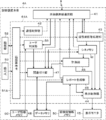
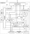
- FIG. 3 is a block diagram showing a configuration of a receiving unit according to the first embodiment of the present invention. It is a figure which shows the example of the head mounted display in Embodiment 1 of this invention.
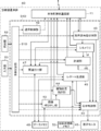
- FIG. 3 is a block diagram showing a configuration of a head mounted display according to Embodiment 1 of the present invention. It is a block diagram which shows the structure of the diagnostic device main body in Embodiment 1 of this invention.
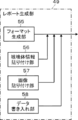
- FIG. 3 is a block diagram showing a configuration of a report generation unit according to the first embodiment of the present invention.
- FIG. 3 is a flowchart showing the operation of the ultrasonic diagnostic apparatus according to Embodiment 1 of the present invention. It is a figure which shows the example of the head mounted display in Embodiment 2 of this invention.
- FIG. 6 is a block diagram showing a configuration of a head mounted display according to Embodiment 2 of the present invention. It is a block diagram which shows the structure of the diagnostic device main body in Embodiment 2 of this invention. It is a block diagram which shows the structure of the head mounted display in Embodiment 3 of this invention. It is a block diagram which shows the structure of the diagnostic device main body in Embodiment 3 of this invention.
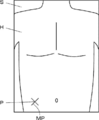
- FIG. 16 is a diagram illustrating an example of a plurality of thumbnail images displayed as a list in Embodiment 4 of the present invention. It is a block diagram which shows the structure of the diagnostic device main body in Embodiment 5 of this invention. It is a figure which shows the example of the visual field image in which the contact position of the ultrasonic probe in the last inspection was highlighted in Embodiment 5 of this invention. It is a block diagram which shows the structure of the diagnostic device main body in Embodiment 6 of this invention. It is a block diagram which shows the structure of the ultrasonic diagnosing device which concerns on Embodiment 7 of this invention.
- the numerical range represented by “to” means the range including the numerical values before and after “to” as the lower limit value and the upper limit value.
- the terms “vertical” and “parallel” include the range of error allowed in the technical field to which the present invention belongs. For example, “vertical” and “parallel” means within a range of less than ⁇ 10° with respect to strict vertical or parallel, and an error with respect to strict vertical or parallel is 5° or less. Is preferable, and more preferably 3° or less.
- “identical” and “identical” include an error range generally accepted in the technical field. Further, in the present specification, when referring to “all”, “all” or “entire surface” and the like, in addition to the case of 100%, including an error range generally accepted in the technical field, for example, 99% or more, The case where it is 95% or more, or 90% or more is included.
- FIG. 1 shows the configuration of an ultrasonic diagnostic apparatus 1 according to Embodiment 1 of the present invention.
- the ultrasonic diagnostic apparatus 1 includes an ultrasonic probe 2, a head mounted display 3, and a diagnostic apparatus main body 4, and the ultrasonic probe 2 and the head mounted display 3 are connected to the diagnostic apparatus main body 4 in a wireless state.
- the head-mounted display 3 is a display device that is mounted on the user's head and is viewed by the user who is wearing the head-mounted display 3.
- An ultrasonic image or the like is wirelessly transmitted from the diagnostic apparatus body 4 to the head-mounted display 3 and transmitted.
- the ultrasonic image and the like are displayed on the head mounted display 3.
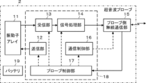
- the ultrasonic probe 2 includes a transducer array 11, and a transmitter 12 and a receiver 13 are connected to the transducer array 11, respectively.
- the signal processing unit 14 and the probe-side wireless communication unit 15 are sequentially connected to the receiving unit 13.
- the communication control unit 16 is connected to the probe-side wireless communication unit 15.
- the probe controller 17 is connected to the transmitter 12, the receiver 13, the signal processor 14, the probe-side wireless communication unit 15, and the communication controller 16, and the transmitter 12, the receiver 13, and the signal processor 14 are connected.
- the communication controller 16 and the probe controller 17 constitute a probe processor 18.
- a battery 19 is built in the ultrasonic probe 2.
- the transducer array 11 of the ultrasonic probe 2 shown in FIG. 2 has a plurality of transducers arranged one-dimensionally or two-dimensionally. Each of these transducers transmits an ultrasonic wave in accordance with a drive signal supplied from the transmission unit 12, receives an ultrasonic echo from the subject, and outputs a signal based on the ultrasonic echo.
- Each oscillator is, for example, a piezoelectric ceramic typified by PZT (Lead Zirconate Titanate), a polymer piezoelectric element typified by PVDF (PolyVinylidene DiFluoride), and a PMN-PT ( Lead Magnesium Niobate-Lead Titanate: Lead magnesium niobate-lead titanate solid solution) is formed by forming electrodes on both ends of a piezoelectric body such as a piezoelectric single crystal.
- PZT Lead Zirconate Titanate
- PVDF PolyVinylidene DiFluoride
- PMN-PT Lead Magnesium Niobate-Lead Titanate: Lead magnesium niobate-lead titanate solid solution
- the transmission unit 12 of the probe processor 18 includes, for example, a plurality of pulse generators, and a plurality of vibrations of the transducer array 11 are generated based on the transmission delay pattern selected according to the control signal from the probe control unit 17.
- the respective drive signals are supplied to the plurality of transducers by adjusting the delay amount so that the ultrasonic waves transmitted from the child form an ultrasonic beam.
- a pulsed or continuous wave voltage is applied to the electrodes of the vibrators of the vibrator array 11
- the piezoelectric body expands and contracts, and pulsed or continuous wave ultrasonic waves are generated from the respective vibrators.
- An ultrasonic beam is formed from a composite wave of those ultrasonic waves.
- the transmitted ultrasonic beam is reflected by a target such as a site of a subject and propagates toward the transducer array 11 of the ultrasonic probe 2.
- the ultrasonic waves propagating toward the transducer array 11 in this manner are received by the respective transducers forming the transducer array 11.
- each transducer forming the transducer array 11 expands and contracts by receiving the propagating ultrasonic echo to generate an electric signal, and outputs these electric signals to the receiving unit 13.
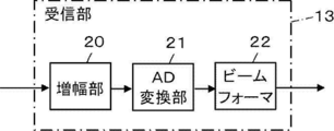
- the receiving unit 13 of the probe processor 18 processes the signal output from the transducer array 11 according to the control signal from the probe control unit 17. As shown in FIG. 3, the reception unit 13 has a configuration in which an amplification unit 20, an AD (Analog Digital) conversion unit 21, and a beam former 22 are connected in series.
- AD Analog Digital
- the amplifying unit 20 amplifies the signals input from the respective oscillators forming the oscillator array 11, and transmits the amplified signals to the AD converting unit 21.
- the AD conversion unit 21 converts the signal transmitted from the amplification unit 20 into digital data, and transmits these data to the beamformer 22.
- the beamformer 22 follows each of the data converted by the AD converter 21 according to the sound velocity or the distribution of the sound velocity set based on the reception delay pattern selected according to the control signal from the probe controller 17.
- a so-called reception focus process is performed by giving a delay and adding. By this reception focus processing, the reception signals obtained by subjecting each data converted by the AD conversion unit 21 to phasing addition and narrowing the focus of the ultrasonic echo are acquired.
- the signal processing unit 14 of the probe processor 18 performs an envelope detection process on the reception data generated by the reception unit 13 after performing attenuation correction by distance according to the depth of the reflection position of the ultrasonic wave. , An ultrasonic image signal, which is tomographic image information regarding the tissue in the subject is generated.
- the probe-side wireless communication unit 15 of the ultrasonic probe 2 includes an antenna for transmitting and receiving radio waves, modulates a carrier based on the ultrasonic image signal generated by the signal processing unit 14, and transmits ultrasonic waves.
- a transmission signal representing the image signal is generated.
- the probe-side wireless communication unit 15 supplies the transmission signal representing the ultrasonic image signal thus generated to the antenna and transmits the radio wave from the antenna, thereby sequentially transmitting the ultrasonic image signal to the diagnostic apparatus body 4.
- Carrier modulation methods include ASK (Amplitude Shift Keying), PSK (Phase Shift Keying), QPSK (Quadrature Phase Shift Keying), and 16QAM (16 Quadrature Amplitude).
- the probe-side wireless communication unit 15 also receives instruction information or the like for instructing the operation of the ultrasonic probe 2 from the diagnostic apparatus body 4, and inputs the received instruction information or the like to the probe control unit 17.
- the communication control unit 16 of the probe processor 18 controls the probe-side wireless communication unit 15 so that the ultrasonic image signal is transmitted with the transmission radio field intensity set by the probe control unit 17.
- the probe control unit 17 of the probe processor 18 controls each unit of the ultrasonic probe 2 based on a program stored in advance, instruction information wirelessly transmitted from the diagnostic apparatus body 4, and the like.
- the battery 19 of the ultrasonic probe 2 is built in the ultrasonic probe 2 and supplies electric power to each circuit of the ultrasonic probe 2.
- the probe processor 18 including the transmission unit 12, the reception unit 13, the signal processing unit 14, the communication control unit 16, and the probe control unit 17 performs various processing on the CPU (Central Processing Unit) and the CPU. It consists of a control program to execute, FPGA (Field Programmable Gate Array: Feed Programmable Gate Array), DSP (Digital Signal Processor: Digital Signal Processor), ASIC (Application Specific Integrated Circuit): Application Specific Integrated Circuit, It may be configured by using another IC (Integrated Circuit), or may be configured by combining them. Further, the transmission unit 12, the reception unit 13, the signal processing unit 14, the communication control unit 16, and the probe control unit 17 can be partially or wholly integrated into one CPU or the like.
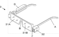
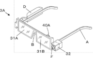
- the head mounted display 3 is a display device that is mounted on the user's head and is visually recognized by the user who is mounted, and has a so-called eyeglass-like shape as shown in FIG.
- the head mounted display 3 includes two display portions 31A and 31B, and the two display portions 31A and 31B are connected to each other by a bridge portion B, and the vine portions are respectively provided at the ends of the two display portions 31A and 31B. A is connected.
- the bridge portion B is caught on the user's nose and the two vine portions A are caught on the user's ears, whereby the head mounted display 3 is fixed to the head of the subject.
- the two display units 31A and 31B face the left and right eyes of the user, respectively.
- a visual field camera unit 32 having a taking lens F arranged on the front surface is attached to a connecting portion between the left display unit 31B and the vine A. Further, in the vine portion A connected to the display portion 31A on the right side, a storage portion D in which various circuits necessary for the operation of the head mounted display 3, a battery and the like are stored is arranged.
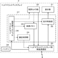
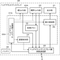
- FIG. 5 shows the configuration of the head mounted display 3.
- the head mounted display 3 has a head mounted display side wireless communication section 33, and the head mounted display side wireless communication section 33 is connected to a visual field camera section 32, a communication control section 34, a display control section 35 and an image memory 39.
- the display unit 31 is connected to the display control unit 35.
- the visual field camera unit 32 is connected to the image memory 39.
- a head mount display control unit 36 is connected to the visual field camera unit 32, the head mounted display side wireless communication unit 33, the communication control unit 34, the display control unit 35, and the image memory 39.
- the two display units 31A and 31B in FIG. 4 are collectively referred to as the display unit 31.
- the communication controller 34, the display controller 35, the head mounted display controller 36 and the image memory 39 constitute a head mounted display processor 37.
- a battery 38 is built in the head mounted display 3.
- the head mounted display side wireless communication unit 33, the head mounted display processor 37 and the battery 38 are housed in the housing unit D of the head mounted display 3.
- the field-of-view camera unit 32 of the head mounted display 3 generates a field-of-view image obtained by shooting the field of view in front of the user through the shooting lens F.
- the visual field camera unit 32 photographs the visual field in front of the user through the photographing lens F and amplifies the visual field image signal acquired by the image sensor and the visual field image signal which is an analog signal.
- An analog signal processing circuit for converting the converted digital signal into a digital signal and a digital signal processing circuit for performing various corrections such as gain correction on the converted digital signal to generate a visual field image are incorporated.
- the analog signal processing circuit and the digital signal processing circuit may be incorporated in the head mounted display processor 37.
- the visual field camera unit 32 can give a so-called time stamp, which represents the time when the visual field image is generated, to the generated visual field image.
- the display unit 31 of the head-mounted display 3 has a light-transmitting property in order to secure the user's visual field when the user wears the head-mounted display 3. Further, the display unit 31 is a display display that displays an ultrasonic image and the like. Since the display unit 31 has such a configuration, it can display, for example, an ultrasonic image or the like transmitted from the diagnostic apparatus body 4.
- the image memory 39 of the head-mounted display processor 37 is a memory that sequentially receives the visual field images generated by the visual field camera unit 32, and temporarily holds the received visual field images under the control of the head-mounted display control unit 36. Is.
- the image memory 39 sequentially holds the visual field images received from the visual field camera unit 32, and when the number of retained visual field images exceeds a preset number, the visual field images first retained are sequentially displayed. The visual field images newly received from the visual field camera unit 32 are sequentially overwritten.
- the visual field image temporarily held in the image memory 39 is sent to the head mounted display side wireless communication unit 33 under the head mounted display control unit 36.
- a RAM Random Access Memory
- the display control unit 35 of the head mounted display processor 37 under the control of the head mounted display control unit 36, performs a predetermined process on the ultrasonic image or the like transmitted from the diagnostic apparatus body 4, and causes the display unit 31 to display the ultrasonic image. Etc. are displayed.
- the communication control unit 34 of the head-mounted display processor 37 uses the head-mounted display-side wireless communication unit so that the field-of-view image is transmitted and the ultrasonic image and the like are transmitted at the transmission/reception field intensity set by the head-mounted display control unit 36. Control 33.
- the head-mounted display control unit 36 of the head-mounted display processor 37 controls each unit of the head-mounted display 3 based on a prestored program, instruction information wirelessly transmitted from the diagnostic apparatus body 4, and the like.
- the battery 38 of the head mounted display 3 is built in the head mounted display 3 and supplies electric power to each circuit of the head mounted display 3.
- the head mount display processor 37 including the communication control unit 34, the display control unit 35, the head mount display control unit 36, and the image memory 39 has a CPU and various CPUs, like the probe processor 18 of the ultrasonic probe 2. It is composed of a control program for performing the processing of, but may be configured using FPGA, DSP, ASIC, GPU (Graphics Processing Unit), or other IC, or by combining them. It may be configured.
- the communication control unit 34, the display control unit 35, the head mounted display control unit 36, and the image memory 39 can be partially or wholly integrated into one CPU or the like.
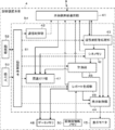
- the diagnostic device main body 4 has a main body side wireless communication unit 41, and a communication control unit 42 is connected to the main body side wireless communication unit 41.
- An ultrasonic image processing unit 43, a display control unit 44, and a display monitor 45 are sequentially connected to the main body side wireless communication unit 41.
- the cine memory M is connected to the ultrasonic image processing unit 43, and the main body side wireless communication unit 41, the display control unit 44, and the measuring unit 46 are connected to the cine memory M.
- the main body side wireless communication unit 41 and the display control unit 44 are connected to the measuring unit 46.
- An associating unit 47 is connected to the main body side wireless communication unit 41, the cine memory M, and the measuring unit 46, and a data memory 48 is connected to the associating unit 47.
- the associating unit 47 and the data memory 48 are connected so that information can be passed bidirectionally.
- a report generation unit 49 is connected to the data memory 48, and a subject information memory 50 is connected to the report generation unit 49.
- the report generation unit 49 and the data memory 48 are connected so that information can be passed bidirectionally.
- the main body side wireless communication unit 41 and the display control unit 44 are connected to the report generation unit 49.
- main body control unit 51 is connected to the communication control unit 42, the ultrasonic image processing unit 43, the display control unit 44, the cine memory M, the measuring unit 46, the associating unit 47, and the report generating unit 49, and the main body control unit 51 is connected to the main body control unit 51.
- the storage unit 52 and the input unit 53 are connected.
- the main body control unit 51 and the storage unit 52 are connected so that information can be passed bidirectionally.
- the communication control unit 42, the ultrasonic image processing unit 43, the display control unit 44, the cine memory M, the measuring unit 46, the associating unit 47, the report generating unit 49, and the main body control unit 51 constitute a diagnostic device main body processor 54. There is.
- the main body side wireless communication unit 41 of the diagnostic apparatus main body 4 transmits and receives radio waves similarly to the probe side wireless communication unit 15 of the ultrasonic probe 2 and the head mounted display side wireless communication unit 33 of the head mounted display 3.
- the wireless communication unit transmits the instruction information and the like to the probe-side wireless communication unit 15 and the head-mounted display-side wireless communication unit 33 and receives the ultrasonic image signal, the visual field image, and the like by wireless communication.
- the ultrasonic image processing unit 43 of the diagnostic apparatus main body processor 54 receives the ultrasonic image signal transmitted from the ultrasonic probe 2 via the main body side wireless communication unit 41, and based on the received ultrasonic image signal, ultrasonic waves are transmitted. Generate an image. At this time, the ultrasonic image processing unit 43 first generates an ultrasonic image by converting (raster conversion) the ultrasonic image signal into an image signal according to a normal television signal operation method. In addition, the ultrasonic image processing unit 43 performs various necessary image processing such as gradation processing on the generated ultrasonic image, and then the processed ultrasonic image is transmitted to the main body side wireless communication unit 41. Output to the display control unit 44 and the cine memory M.
- the ultrasonic image output to the main body side wireless communication unit 41 is transmitted to the head mounted display 3 by wireless communication.
- the ultrasonic image processing unit 43 can add a so-called time stamp, which represents the time when the ultrasonic image is generated, to the generated ultrasonic image.
- the cine memory M of the diagnostic apparatus main body processor 54 sequentially receives the ultrasonic images generated by the ultrasonic image processing section 43, and temporarily holds the received ultrasonic images under the control of the main body control section 51. It is a memory.
- the cine memory M sequentially holds, for example, the ultrasonic images received from the ultrasonic image processing unit 43, and when a predetermined time has elapsed from the time when the ultrasonic images were first held, The ultrasonic images newly received from the ultrasonic image processing unit 43 are sequentially overwritten in order.
- the ultrasonic image temporarily stored in the cine memory M is sent to the main body side wireless communication unit 41, the display control unit 44, and the association unit 47 under the main body control unit 51.
- a RAM or the like is used as the cine memory M, for example.
- the measuring unit 46 of the diagnostic apparatus main body processor 54 measures the subject based on the ultrasonic image generated by the ultrasonic image processing unit 43 and stored in the cine memory M. For example, when a blood vessel is drawn on the ultrasonic image, the measurement unit 46 sets a so-called measurement caliper for measuring the length between two points on the ultrasonic image, and sets the set measurement caliper. It can be used to measure the thickness of the blood vessel wall, the blood vessel diameter, and the like. At this time, the position of the measurement caliper can be appropriately adjusted by the user via the input unit 53, for example. The measurement result obtained by the measurement unit 46 is sent to the main body side wireless communication unit 41, the display control unit 44, and the association unit 47.
- the associating unit 47 of the diagnostic apparatus main body processor 54 associates the ultrasonic image and the visual field image captured at the same timing by the ultrasonic probe 2 and the visual field camera unit 32 of the head mounted display 3 with each other in the data memory 48. save.
- the ultrasonic image processing unit 43 gives a time stamp indicating the time when the ultrasonic image is generated to the ultrasonic image
- the visual field camera unit 32 of the head mounted display 3 causes the visual field image to be displayed.
- the associating unit 47 regards the time stamp of the ultrasonic image as indicating the time at which the ultrasonic image was captured, and the time stamp of the visual field image is regarded as the time stamp. It is possible to correlate the ultrasonic image and the visual field image, which are captured at the same timing, with each other by referring to the time stamps of the ultrasonic image and the visual field image, by regarding the time when the image was captured.
- the associating unit 47 refers to, for example, the time stamp of the ultrasonic image and the time stamp of the visual field image to determine the time when the ultrasonic image was captured and the visual field image. If the difference from the time of photographing is within a certain range, for example, within 0.1 second, it is considered that the ultrasonic image and the visual field image were photographed at the same timing, and the association is performed. Further, the associating unit 47 refers to, for example, the time stamp of the ultrasonic image and the time stamp of the visual field image, and the visual field image captured at the time closest to the time when the ultrasonic image to be associated is captured.
- the associating unit 47 selects one ultrasonic image from a plurality of ultrasonic images temporarily stored in the cine memory M by the user via the input unit 53 or the like, and selects the selected ultrasonic image, for example.
- the ultrasonic wave image saved in the data memory 48 and the view image taken at the same timing as the ultrasonic image can be associated with each other. it can.
- the associating unit 47 compares the ultrasonic image and the visual field image stored in the data memory 48. , The measurement results are associated with each other, and the associated measurement results are stored in the data memory 48. At this time, the associating unit 47 can superimpose the measurement result on the ultrasonic image and store the measurement result in the data memory 48, for example.
- the associating unit 47 can also store the measurement result in the data memory 48 as text data, for example.
- the associating unit 47 converts the inputted examination information into an ultrasonic image and a visual field.
- the data and the measurement result are stored in the data memory 48 in association with each other.
- the data memory 48 of the diagnostic apparatus body 4 is a memory that stores the ultrasonic image, the visual field image, the measurement result, the inspection information, and the like associated by the associating unit 47.
- Examples of the data memory 48 include a flash memory, an HDD (Hard Disc Drive: hard disk drive), an SSD (Solid State Drive: solid state drive), an FD (Flexible Disc: flexible disc), and an MO disk (Magneto-Optical Disc: optical).
- Magnetic disk Magnetic disk
- MT Magnetic Tape: magnetic tape
- RAM Compact Disc
- CD Compact Disc
- DVD Digital Versatile Disc: Digital Versatile disc
- SD card Secure Digital card
- USB memory Universal Serial Bus memory: A recording medium such as a universal serial bus memory or a server can be used.
- the subject information memory 50 of the diagnostic apparatus body 4 stores the IDs of a plurality of subjects, examination history, name, age, sex, physical data such as height and weight, and subjects such as basic diseases on which the subject suffers. It stores information and is used as a so-called database.
- the ultrasonic diagnostic apparatus 1 is used in a hospital
- subject information of a subject who has been examined in the hospital is stored.
- the electronic medical record database is connected to the network in the hospital, the subject information is acquired from the electronic medical record database via the network, and the acquired subject information is stored in the subject information memory. 50 may be stored.
- object information memory 50 similar to the data memory 48, for example, a flash memory, HDD, SSD, FD, MO disk, MT, RAM, CD, DVD, SD card, a recording medium such as a USB memory, a server, or the like. Is used.
- the report generation unit 49 of the diagnostic apparatus main body processor 54 generates a report in which both the ultrasonic image and the visual field image, which are associated with each other by the association unit 47 and are stored in the data memory 48, are pasted.
- the report generation unit 49 includes a format generation unit 55, a subject information pasting unit 56, an image pasting unit 57, and a data writing unit 58.
- the format generation unit 55 of the report generation unit 49 stores the defined format of the report and generates the stored format.
- the report format corresponds to the mount of the report, and the format includes, for example, as shown in FIG. 8, the subject information J such as the title T of the report R, the subject ID, and the examination history. , The visual field image S, the ultrasonic image U, the user's findings Q, the report creator's name N, etc. are defined.
- the format may include the title T of the report R and the item name of each described item. In FIG. 8, the report T has a title T of “ultrasound diagnostic report”.
- the format generation unit 55 can also store the format set by the user via the input unit 53, for example.
- the subject information pasting unit 56 of the report generation unit 49 determines the subject ID, examination history, name, age, etc. based on the subject ID, name, etc. input by the user via the input unit 53, etc.
- the object information J is pasted in the format of the report R generated by the format generation unit 55.
- the subject information pasting unit 56 refers to the subject information memory 50, identifies the subject from the ID or the like input by the user, and stores the identified subject in the subject information memory 50.
- the subject information J that has been displayed is pasted in the format of the report R. In the report R illustrated in FIG.
- the subject information pasting unit 56 instead of referring to the subject information memory 50, stores the electronic medical chart via the network. It is also possible to retrieve the subject's ID, name, etc. from the database and acquire the subject information J corresponding to the retrieved subject's ID, name, etc.
- the image pasting unit 57 of the report generation unit 49 generates the ultrasonic image U and the visual field image S, which are associated with each other by the association unit 47 and stored in the data memory 48, by the format generation unit 55 as illustrated in FIG. 8. Paste it in the format of the created report R. Further, when the association unit 47 associates the measurement result of the measurement unit 46 with the ultrasonic image U and the visual field image S, the image pasting unit 57, for example, although not shown, displays the measurement result by ultrasonic waves. It is superimposed on the image U and pasted in the format of the report R.
- the subject information J is attached by the subject information attaching unit 56 to the format of the report R generated by the format generating unit 55, and the ultrasonic image U and the visual field are detected by the image attaching unit 57.
- the report R is generated by pasting the image S.
- the generated report R is sent to the main body side wireless communication unit 41, the display control unit 44, and the data memory 48. Note that, for example, when the electronic medical record database is connected to the network in the hospital, the generated report R may be sent to the electronic medical record database via the network.
- the data writing unit 58 of the report generation unit 49 writes the data such as text input by the user via the input unit 53 into the format generated by the format generation unit 55. For example, when the user inputs the report creator's name at the start of the examination of the subject, the data writing unit 58 displays the report creator's name N input by the user as shown in FIG. Can be written in the format. Further, for example, the data writing unit 58 can also write the measurement result by the measuring unit 46 in the column of the observation content Q or the like.
- the display control unit 44 of the diagnostic apparatus main body processor 54 under the control of the main body control unit 51, predetermines the ultrasonic image U generated by the ultrasonic image processing unit 43, the report R generated by the report generating unit 49, and the like. After processing, the display monitor 45 displays the ultrasonic image U, the report R, and the like.
- the display monitor 45 of the diagnostic apparatus body 4 displays an image under the control of the display control unit 44, and is, for example, a display such as an LCD (Liquid Crystal Display) or an organic EL display (Organic Electroluminescence Display). Including equipment.
- the main body control unit 51 of the diagnostic device main body processor 54 controls each unit of the diagnostic device main body 4 based on a program stored in advance in the storage unit 52 or the like and a user's input operation via the input unit 53.
- the communication control unit 42 of the diagnostic device main body processor 54 controls the main body side wireless communication unit 41 so that data is transmitted and received at the transmission and reception radio wave intensity set by the main body control unit 51.
- the input unit 53 of the diagnostic apparatus body 4 is for a user to perform an input operation, and can be configured to include a keyboard, a mouse, a trackball, a touch pad, a touch panel, and the like.
- the storage unit 52 of the diagnostic apparatus main body 4 stores the operation program of the diagnostic apparatus main body 4, and the like as the storage unit 52, like the data memory 48 and the subject information memory 50, for example, a flash memory, an HDD, A recording medium such as SSD, FD, MO disc, MT, RAM, CD, DVD, SD card, USB memory, or the like, or a server or the like is used.
- the diagnostic device main body processor 54 including the communication control unit 42, the ultrasonic image processing unit 43, the display control unit 44, the measurement unit 46, the association unit 47, the cine memory M, the report generation unit 49, and the main body control unit 51 uses the ultrasonic wave. Similar to the probe processor 18 of the probe 2 and the head mounted display processor 37 of the head mounted display 3, it is composed of a CPU and a control program for causing the CPU to perform various processes.
- the FPGA, DSP, ASIC, GPU , Other ICs may be used, or they may be combined.
- the communication control unit 42, the ultrasonic image processing unit 43, the display control unit 44, the measurement unit 46, the association unit 47, the cine memory M, the report generation unit 49, and the main body control unit 51 are partially or wholly integrated. It can also be configured by being integrated with a CPU or the like.
- step S1 the user inputs the examination information including the ID of the subject and the examination site via the input unit 53 of the diagnostic apparatus body 4.
- the name of the subject may be input instead of the ID of the subject.
- the name of the user who is the inspector, that is, the report creator name N may be input by the user.
- step S2 an ultrasonic image U is captured by the ultrasonic probe 2.
- an ultrasonic beam is transmitted from the transducer array 11 toward the inside of the subject while the user keeps the ultrasonic probe 2 in contact with the subject, and an ultrasonic echo from the subject is transmitted by the transducer array 11.
- Received to generate a received signal When the signal processing unit 14 of the ultrasonic probe 2 processes the received signal to generate an ultrasonic image signal, the generated ultrasonic image signal is transmitted to the diagnostic apparatus body 4 by wireless communication, and the diagnostic apparatus body 4 An ultrasonic image is generated by the ultrasonic image processing unit 43.
- the ultrasonic image processing unit 43 adds a time stamp indicating the time when the ultrasonic image U is generated, to the generated ultrasonic image U. Since the time from the start of capturing the ultrasonic image U by the ultrasonic probe 2 to the actual generation of the ultrasonic image U is very short, the time assigned to the ultrasonic image U will be hereafter calculated. The stamp is considered to represent the time when the ultrasonic image U was captured.
- the ultrasonic image U generated by the ultrasonic image processing unit 43 and provided with the time stamp is sent to the main body side wireless communication unit 41, the cine memory M, and the display control unit 44.
- the ultrasonic image U sent to the main body side wireless communication unit 41 is wirelessly transmitted to the head mounted display 3 and displayed on the display unit 31 of the head mounted display 3. Further, the ultrasonic image U sent to the display control unit 44 is displayed on the display monitor 45 of the diagnostic apparatus body 4. Further, the ultrasonic image U sent to the cine memory M is temporarily held in the cine memory M, for example, until a certain time has elapsed since it was received by the cine memory M.
- step S3 the visual field camera unit 32 of the head mounted display 3 photographs the visual field in front of the user, and a visual field image S representing the photographed visual field is generated.
- a visual field image S representing a state in which the ultrasonic probe 2 is in contact with the subject is generated.
- the visual field camera unit 32 gives a time stamp indicating the time when the visual field image S was generated. In this way, the visual field image S generated by the visual field camera unit 32 and provided with the time stamp is temporarily stored in the image memory 39 of the head mounted display 3, for example, for a predetermined time after being received by the image memory 39. Will be held until.
- step S3 is performed after the process of step S2 is completed, but in reality, the processes of step S2 and step S3 are performed at substantially the same time. To do.
- step S4 it is determined whether or not the ultrasonic image U generated in step S2 and displayed on the display unit 31 of the head mounted display 3 and the display monitor 45 of the diagnostic apparatus body 4 is freeze-displayed. It For example, when the user gives an instruction to freeze-display the ultrasonic image U via the input unit 53 of the diagnostic apparatus body 4, the ultrasonic image U is freeze-displayed.
- freeze-displaying the ultrasonic image U means that the ultrasonic images U continuously generated by the ultrasonic image processing unit 43 are sequentially displayed on the display unit 31 of the head mounted display 3 and the display monitor of the diagnostic apparatus body 4. In the state of being displayed on 45, the display of the ultrasonic image U is temporarily stopped, and one stationary ultrasonic image U is displayed on the display unit 31 of the head mounted display 3 and the display monitor 45 of the diagnostic apparatus body 4. Say that.
- step S4 When it is determined in step S4 that the ultrasonic image U is not freeze-displayed, the process returns to step S2, a new ultrasonic image U is captured and generated, and the generated ultrasonic image U is head mounted. It is displayed on the display unit 31 of the display 3 and the display monitor 45 of the diagnostic apparatus main body 4, and is held in the cine memory M. In the subsequent step S3, a new field-of-view image S is captured and generated, and the generated field-of-view image S is held in the image memory 39 of the head mounted display 3. When the process of step S3 is performed, the process proceeds to step S4, and it is determined whether or not the ultrasonic image U is freeze-displayed.
- steps S2 to S4 are repeated until it is determined in step S4 that the ultrasonic image U is freeze-displayed. Further, by repeating the processing of steps S2 to S4, a plurality of visual field images S are held in the image memory 39 of the head mounted display 3, and a plurality of ultrasonic images U are held in the cine memory M of the diagnostic apparatus body 4. It
- step S4 the ultrasonic image U is freeze-displayed on the display unit 31 of the head mounted display 3 and the display monitor 45 of the diagnostic apparatus body 4 according to the user's instruction via the input unit 53, and the ultrasonic image U is frozen-displayed. If it is determined that there is, the process proceeds to step S5.
- the cine memory M stops receiving the ultrasonic image U from the ultrasonic image processing unit 43 under the control of the main body control unit 51. Then, the ultrasound image U currently held in the cine memory M is continuously held.
- the instruction information for freeze-displaying the ultrasonic image U which is input by the user via the input unit 53 of the diagnostic apparatus main body 4, is transmitted to the head mounted display 3 via the main body side wireless communication unit 41. ..
- the instruction information thus transmitted is sent to the head mounted display control unit 36, and under the control of the head mounted display control unit 36, the image memory 39 stops receiving the visual field image S from the visual field camera unit 32. Then, the visual field image S currently held in the image memory 39 is continuously held.
- step S5 it is determined whether the user has given an instruction to save the ultrasonic image U used for the report R in the data memory 48.
- a plurality of display units 31 of the head mounted display 3 and the display monitor 45 of the diagnostic device body 4 are held in the cine memory M of the diagnostic device body 4.
- the ultrasonic images U are displayed in a list, and the user selects one ultrasonic image U to be used for the report R from the plurality of ultrasonic images U displayed in the list, and further, the selected ultrasonic image U.
- An instruction is given to save U in the data memory 48.
- the display unit 31 of the head mounted display 3 is instructed by the user via the input unit 53. Then, the freeze display of the ultrasonic image U on the display monitor 45 of the diagnostic apparatus body 4 is canceled.
- step S6 When it is determined that the user has not given an instruction to save the ultrasonic image U used for the report R in the data memory 48, the freeze of the ultrasonic image U is instructed by the user via the input unit 53. The display is canceled, the process returns to step S2, and the processes of steps S2 to S5 are newly performed. When it is determined that the user has given an instruction to save the ultrasonic image U used for the report R in the data memory 48, the process proceeds to step S6.
- step S6 the associating unit 47 of the diagnostic apparatus body 4 associates the ultrasonic image U for which the saving instruction is given in step S5 with the visual field image S captured at the same timing as the ultrasonic image U with each other. And stored in the data memory 48.
- the associating unit 47 refers to the time stamp given to the ultrasonic image U and the time stamp given to the visual field image S to refer to the ultrasonic image U and the visual field image S taken at the same timing. Relate to each other.
- the associating unit 47 associates the examination information input in step S1 with the ultrasound image U and the visual field image S stored in the data memory 48 and stores the examination information in the data memory 48.
- step S7 the measuring unit 46 of the diagnostic apparatus body 4 determines whether or not the measurement based on the ultrasonic image U is performed. For example, for the ultrasonic image U selected by the user in step S5, a caliper that measures the length between two points on the image is set by the measuring unit 46, and according to the user's input operation via the input unit 53. Length measurements can be made. When it is determined in step S7 that such measurement is not performed, the process proceeds to step S9.
- step S8 the measurement result obtained in step S7 is associated with the ultrasonic image U and the visual field image S that are associated with each other in step S6 and are stored in the data memory 48 by the association unit 47 of the diagnostic apparatus body 4 in step S8. The measurement result is stored in the data memory 48. In this way, even when step S8 is completed, the process proceeds to step S9 as in the case where it is determined in step S7 that the measurement by the measuring unit 46 is not performed.
- the report generation unit 49 of the diagnostic device body 4 attaches the ultrasonic image U and the visual field image S associated in step S6 to each other as shown in FIG.
- the ultrasonic image U, the visual field image S, and the report R to which the measurement results are pasted are generated in S7.
- the report generation unit 49 refers to the object information memory 50 of the diagnostic apparatus body 4 based on the inspection information such as the ID of the object input by the user in step S1, and determines the ID of the object and the previous time.
- the presence/absence of the examination, body data such as the name, age, sex, height and weight of the subject, and subject information J such as underlying diseases are automatically attached to the report R.
- the report generator 49 writes the report creator name N in the report R.
- the subject information pasting unit 56 does not refer to the subject information memory 50, but stores the electronic medical record via the network. It is also possible to retrieve the subject's ID, name, etc. from the database and acquire the subject information J corresponding to the retrieved subject's ID, name, etc.
- the report generation unit 49 automatically generates the report R to which the ultrasonic image U, the visual field image S, and the subject information J associated with each other are attached, so that the effort of the user to create the report R is reduced. Will be reduced.
- step S10 the report R generated in step S9 is saved in the data memory 48 of the diagnostic apparatus body 4. Further, at this time, the report R generated in step S9 is transmitted to the head mounted display 3 by wireless communication and is also transmitted to the display control unit 44 of the diagnostic apparatus body 4 to be displayed on the display unit of the head mounted display 3. 31 and the display monitor 45 of the diagnostic apparatus main body 4. As a result, the operation of the ultrasonic diagnostic apparatus 1 ends.
- the ultrasonic diagnostic apparatus 1 according to the first embodiment of the present invention, the ultrasonic image U and the visual field captured by the visual field camera unit 32 of the ultrasonic probe 2 and the head mounted display 3 at the same timing.
- the image S is associated with each other by the associating unit 47 of the diagnostic device body 4, and the report R in which the ultrasonic image U and the visual field image S associated with each other are pasted by the report generating unit 49 of the diagnostic device body 4. Since it is automatically generated, the user's labor for creating the report R can be reduced.
- the time on the head mounted display 3 and the time on the diagnostic device main body 4 are shared with each other.
- the time on the basis of either the head mounted display 3 or the diagnostic device main body 4 is used. Will be shared.
- a communication protocol such as NTP (Network Time Protocol) or NITZ (Network Identity and Time Zone) is used.
- the time of the built-in clock may be set.
- the method of associating the ultrasonic image U and the visual field image S with each other is limited to the method using the time stamp described above. Not done.
- the photographing timing of the ultrasonic image U by the ultrasonic probe 2 and the photographing timing of the visual field image S by the visual field camera unit 32 of the head mounted display 3 are synchronized.
- the associating unit 47 causes the ultrasonic image U to be detected.
- the ultrasonic image U and the visual field image S can be associated with each other by regarding that the ultrasonic image U and the visual field image S are captured at the same timing.
- the report generation unit 49 of the diagnostic apparatus body 4 reads the subject information read from the subject information memory 50 based on the examination information such as the subject ID and the examination site input by the user via the input unit 53.
- the subject information J may be input by the user via the input unit 53 instead of being automatically attached by the report generation unit 49.
- the ultrasonic image U and the field-of-view image S which are associated with each other by the associating unit 47 and are stored in the data memory 48, are automatically attached to the report R, so that the user's labor for creating the report R is reduced. can do.
- the report R generated by the report generation unit 49 and stored in the data memory 48 can be edited in accordance with a user's input operation via the input unit 53, for example.
- the user selects the report R stored in the data memory 48 via the input unit 53, and the selected report R is displayed on the display unit 31 of the head mounted display 3 or
- the report R displayed on the display monitor 45 of the diagnostic apparatus body 4 and displayed is edited by the user, and the edited report R is stored in the data memory 48.
- the title T, subject information J, findings Q, and report creator name N described in the report R are added, deleted, rewritten, or the like. ..
- the ultrasonic image U generated by the ultrasonic image processing unit 43 of the diagnostic apparatus body 4 the report R generated by the report generating unit 49, and the like are displayed on the display unit 31 of the head mounted display 3.
- the information is displayed on both the display monitors 45 of the diagnostic apparatus body 4, it may be displayed on either the display unit 31 of the head mounted display 3 or the display monitor 45 of the diagnostic apparatus body 4. ..
- the ultrasonic probe 2, the head mounted display 3, and the diagnostic apparatus body 4 are connected to each other by wireless communication, but may be connected by wire instead of using wireless communication.
- the ultrasonic probe 2 and the diagnostic apparatus body 4 can be connected by wire
- the head mounted display 3 and the diagnostic apparatus body 4 can be connected by wire.
- the head mounted display 3 includes a display unit 31 that can be visually recognized by the user and a visual field camera unit 32 that captures a visual field in front of the user and can be mounted on the user's head
- the head mounted display 3 The shape of 3 is not limited to the shape shown in FIG.
- the head mounted display 3 may be provided with only one of the two display units 31A and 31B instead of having both of the two display units 31A and 31B. You may provide one display part.
- the ultrasonic probe 2 may be provided with the ultrasonic image processing section 43 instead of being provided in the diagnostic apparatus body 4.
- the ultrasonic image U is generated by the ultrasonic probe 2, and the generated ultrasonic image U is transmitted to the diagnostic apparatus body 4 via the probe-side wireless communication unit 15.
- the ultrasonic image U transmitted to the diagnostic device main body 4 is input to the display control unit 44 via the main body side wireless communication unit 41 of the diagnostic device main body 4 and also from the main body side wireless communication unit 41. Sent to.
- the ultrasonic image U transmitted to the head mounted display 3 is input to the display control unit 35 via the head mounted display side wireless communication unit 33 of the head mounted display 3. At this time, the ultrasonic image U may be directly transmitted from the ultrasonic probe 2 to the head mounted display 3 without passing through the diagnostic apparatus body 4.
- Embodiment 2 In the first embodiment, the report creator name N is described in the report R in accordance with the user's input operation via the input unit 53 of the diagnostic apparatus body 4, but the creator of the report R, that is, the examination of the subject. It is also possible to automatically discriminate the user who is performing the operation and insert the name of the discriminated user into the report R as the name of the report creator.
- a method of automatically determining the user for example, there is a method of recognizing the retina or iris of the user and determining the user based on the recognized retina or iris.
- the head mounted display 3A in Embodiment 2 captures the user's eyes on the display unit 31B so as to face the user's face. It has an eye camera unit 40A for.
- a prism may be arranged on the display unit 31B, and the eye camera unit 40A arranged on the vine portion A may be configured to photograph the user's eye via the prism.
- an eye camera unit 40A is added to the head mounted display 3 in the first embodiment shown in FIG. 5, and a head mounted display control unit instead of the head mounted display control unit 36.
- 36A is provided in the head mounted display 3A.
- a head mounted display side wireless communication unit 33 and a head mounted display control unit 36A are connected to the eye camera unit 40A.
- the communication controller 34, the display controller 35, the head mounted display controller 36A, and the image memory 39 constitute a head mounted display processor 37A.
- the eye camera unit 40A of the head mounted display 3A generates an eye image of the user's eye.
- the eye camera unit 40 ⁇ /b>A like the visual field camera unit 32, is an image that captures an eye image signal that is an analog signal by capturing an image of the user's eye through the image capturing lens facing the user's eye and the image capturing lens.
- a sensor an analog signal processing circuit that amplifies the eye image signal acquired by the image sensor and converts it into a digital signal, and performs various corrections such as gain correction on the converted digital signal to generate an eye image Built-in digital signal circuit.
- the analog signal processing circuit and the digital signal processing circuit may be incorporated in the head mounted display processor 37A.
- the eye image generated by the eye camera unit 40A is sent to the head-mounted display-side wireless communication unit 33, and the head-mounted display-side wireless communication unit 33 uses wireless communication to perform diagnostic apparatus main body according to the second embodiment. 4A is transmitted.
- the diagnostic device body 4A according to the second embodiment is different from the diagnostic device body 4 according to the first embodiment shown in FIG. 6 in that a user determination unit 59 and a user information memory 60 are added, and the body control is performed.
- a main body control unit 51A is provided instead of the unit 51.
- the main body side wireless communication unit 41 is connected to the user determination unit 59, and the user determination unit 59 is connected to the association unit 47, the main body control unit 51A, and the user information memory 60. Further, the communication control unit 42, the ultrasonic image processing unit 43, the display control unit 44, the cine memory M, the measuring unit 46, the associating unit 47, the report generating unit 49, the main body control unit 51A, and the user determining unit 59 allow the diagnostic apparatus main body processor 54A is configured.
- the user information memory 60 of the diagnostic apparatus body 4A is a database that stores user information in advance, and stores, for example, user eye information and user names in association with each other.
- the information of the user's eyes includes information indicating the pattern of the user's retina or iris.
- user information such as doctors and technicians who inspect the subject in the hospital is input to the user information memory 60.
- the user information memory 60 similar to the data memory 48, the subject information memory, and the storage unit 52, for example, flash memory, HDD, SSD, FD, MO disk, MT, RAM, CD, DVD, SD card, USB memory
- a recording medium such as, or a server or the like is used.
- the user determination unit 59 of the diagnostic apparatus main body processor 54A receives the eye image transmitted from the head mounted display 3A via the main body side wireless communication unit 41, and recognizes the user's retina or iris based on the received eye image. To do. Further, the user determination unit 59 compares the recognized user's retina or iris pattern with the user's retina or iris pattern stored in the user information memory 60, so that the head mounted display 3A is currently mounted. Determine which users are The information of the user's name, that is, the user name determined by the user determination unit 59 in this manner is sent to the association unit 47.
- the associating unit 47 of the diagnostic apparatus main body processor 54A inputs the ultrasonic image U and the visual field image S taken at the same timing by the ultrasonic probe 2 and the visual field camera unit 32 of the head mounted display 3A, the measurement result by the measuring unit 46, and the input.
- the examination information of the subject input by the user via the unit 53 and the user name determined by the user determination unit 59 are associated with each other and stored in the data memory 48.
- the report generation unit 49 of the diagnostic device main body processor 54A associates the ultrasound image U, the visual field image S, the measurement result, and the user name, which are associated with each other by the association unit 47 and stored in the data memory 48, with a format as shown in FIG.
- the report R attached to is generated.
- the data writing unit 58 of the report generating unit 49 determines by the user determining unit 59 that the user name stored in the data memory 48 by the associating unit 47 be the report creator name N and the format generating unit 55. Fill in the format of the generated report R.
- the report R generated by the report generation unit 49 is transmitted to the display unit 31 of the head mounted display 3A via the main body side wireless communication unit 41 and the display control unit 44 of the diagnostic device main body 4 is transmitted. It is sent out to the display monitor 45 via the display unit 31 of the head mounted display 3A and the display monitor 45 of the diagnostic apparatus body 4.
- the eye camera unit 40A of the head mounted display 3A generates an eye image of the user's eye
- the user determination unit of the diagnostic apparatus body 4A refers to the user information memory 60 to determine the user from the retina or iris of the subject in the generated eye image
- the report generation unit 49 automatically reports the determined user name to the report R. It is possible to reduce the effort of the user to create the report R because it is written in.
- the eye camera unit 40A of the head mounted display 3A generates an eye image in which the user's eye is photographed.
- the user blinks or
- the diagnostic apparatus main body 4A can be provided with an unillustrated eye movement detection unit that detects the user's line of sight, that is, the point at which the user is gazing in the front visual field.
- the detected blinking of the user or the movement of the line of sight of the user can be used as an input operation of the user, for example.
- the ultrasonic image U is freeze-displayed under the control of the main body control unit 51A based on the number of blinks of the user detected by the eye movement detection unit, the position of the line of sight of the user, and the like.
- the user can perform the input operation without using the hands even when both hands are closed during the examination of the subject. It can be performed.
- Embodiment 3 Although the user's retina or iris is used to determine the user in the second embodiment, the user's voice may be used to determine the user.
- a head mounted display 3B according to the third embodiment is different from the head mounted display 3A according to the second embodiment shown in FIG. 11 in that a microphone 40B is provided instead of the eye camera unit 40A, and head mounted display control is performed.
- a head mounted display control unit 36B is provided instead of the unit 36A.
- the head-mounted display side wireless communication unit 33 and the head-mounted display control unit 36B are connected to the microphone 40B.
- the communication control unit 34, the display control unit 35, and the head mount display control unit 36B constitute a head mount display processor 37B.
- the microphone 40B of the head mounted display 3B is for acquiring ambient sound.
- the microphone 40B acquires ambient sound as an analog signal, converts the acquired sound into a digital signal, and generates sound data.
- the sound data generated by the microphone 40B is sent to the head-mounted display-side wireless communication unit 33, and is transmitted from the head-mounted display-side wireless communication unit 33 to the diagnostic apparatus body 4B according to the third embodiment using wireless communication. It
- the diagnostic device main body 4B according to the third embodiment is different from the diagnostic device main body 4A according to the second embodiment shown in FIG. 12 in that a voice text generation unit 61 is added and the main body control unit 51A is replaced by the main body.
- the controller 51B is provided.
- a voice text generation unit 61 is connected to the main body side wireless communication unit 41, and a report generation unit 49 and a main body control unit 51B are connected to the voice text generation unit 61.
- the diagnostic device main body processor 54B is configured by the above.
- the user information memory 60 of the diagnostic device main body processor 54B is a database that stores user information in advance, but stores user voice information and user names in association with each other.
- the information of the voice of the user includes information representing the voiceprint of the user.
- the user determination unit 59 of the diagnostic device main body processor 54B receives the sound data transmitted from the head mounted display 3B via the main body side wireless communication unit 41, and recognizes the user's voiceprint based on the received sound data. To do. Furthermore, the user determination unit 59 determines the user currently wearing the head mounted display 3B by matching the recognized voiceprint of the user with the voiceprint of the user stored in the user information memory 60. The information of the user name of the user determined by the user determination unit 59 in this manner is sent to the association unit 47.
- the associating unit 47 of the diagnostic apparatus main body processor 54B inputs the ultrasonic image U and the visual field image S taken at the same timing by the ultrasonic probe 2 and the visual field camera unit 32 of the head mounted display 3A, the measurement result by the measuring unit 46, and the input.
- the examination information of the subject input by the user via the unit 53 and the user name determined by the user determination unit 59 are associated and stored in the data memory 48.
- the voice text generation unit 61 of the diagnostic device main body processor 54B receives the sound data transmitted from the head mounted display 3B via the main body side wireless communication unit 41, and recognizes the user's voice based on the received sound data. , Generate text based on the recognized voice of the user. For example, the voice text generation unit 61 extracts the inspection content and the content regarding the inspection result by performing so-called natural language processing or the like on the recognized voice of the user, and generates the text representing the extracted content. .. The text generated by the voice text generation unit 61 is sent to the report generation unit 49.
- the report generation unit 49 of the diagnostic device main body processor 54B is generated by the ultrasonic image U, the view image S, the measurement result, the user name, and the voice text generation unit 61 that are associated with each other by the association unit 47 and are stored in the data memory 48.
- the generated text is pasted into a format as shown in FIG. 8, for example, to generate a report R.
- the data writing unit 58 of the report generation unit 49 writes the user name determined by the user determination unit 59 and stored in the data memory 48 by the association unit 47 into the report R format as the report creator name N.
- the text generated by the voice text generation unit 61 is written in the format of the report R as the user's observation content Q.
- the report R generated by the report generation unit 49 is transmitted to the display unit 31 of the head mounted display 3A via the main body side wireless communication unit 41 and the display control unit 44 of the diagnostic device main body 4 is transmitted. It is sent out to the display monitor 45 via the display unit 31 of the head mounted display 3A and the display monitor 45 of the diagnostic apparatus body 4.
- the microphone 40B of the head mounted display 3B acquires ambient sound and generates sound data including the data of the user's voice.
- the user discrimination unit 59 of the main body 4A refers to the user information memory 60 to discriminate the user from the voice data of the user included in the generated sound data, and the voice text generation unit 61 is based on the voice of the user. Since the report is generated and the report generation unit 49 automatically writes the user name of the determined user and the generated text in the report R, the user's labor for generating the report R can be reduced.
- the head mounted display 3B is provided with the microphone 40B, but a microphone connected to the diagnostic device body 4B may be installed independently of the head mounted display 3B.
- the user determination unit 59 determines the user name based on the user's voice, and the voice text generation unit 61 generates the text. Since the report generation unit 49 writes the determined user name and the generated text in the report R, the effort of the user to create the report R is reduced.
- the microphone 40B of the head mounted display 3B or a microphone connected to the diagnostic device body 4B independently of the head mounted display 3B generates and generates sound data including the user's voice.
- the voice of the user is recognized from the generated sound data, and the instruction information represented by the recognized voice of the user is sent to the main body control unit 51B.
- the diagnostic device main body Control of each part of 4B may be performed.
- the user makes a statement to the microphone 40B of the head mounted display 3B to freeze display the ultrasonic image U
- the ultrasonic image U is frozen and displayed under the control of the main body control unit 51B.
- the associating unit 47 of the diagnostic apparatus body 4 associates only one set of the ultrasonic image U and the visual field image S captured at the same timing with each other and stores them in the data memory 48. It is also possible to associate and store a plurality of sets of ultrasonic images U and visual field images S.
- a diagnostic device main body 4C according to the fourth embodiment is different from the diagnostic device main body 4 according to the first embodiment shown in FIG. 6 in that a thumbnail image generation unit 62 is added, and the main body control unit 51 is replaced by a main body.
- the control unit 51C is provided.
- the thumbnail image generation unit 62 is connected to the data memory 48, and the main body side wireless communication unit 41, the display control unit 44, and the main body control unit 51C are connected to the thumbnail image generation unit 62.
- the processor 54C is configured.
- the thumbnail image generation unit 62 of the diagnostic device main body processor 54C captures a plurality of ultrasonic images U by the ultrasonic probe 2, and the ultrasonic image processing unit 43 of the diagnostic device main body 4C generates a plurality of ultrasonic images U.
- the visual field camera unit 32 of the head mounted display 3 captures and generates a plurality of visual field images S, and the associating unit 47 associates a plurality of sets of ultrasonic images U and visual field images S with each other and stores them in the data memory 48. Is performed, a plurality of thumbnail images including the ultrasonic image U and the visual field image S that are associated with each other are generated.
- the thumbnail image generation unit 62 based on a user's instruction or the like via the input unit 53, displays the plurality of generated thumbnail images TH on the display unit 31 of the head-mounted display 3 and the diagnosis.
- a list is displayed on the display monitor 45 of the apparatus body 4C.
- nine thumbnail images TH including the ultrasonic image U and the visual field image S that are associated with each other are displayed on the display monitor 45 of the diagnostic apparatus body 4C, and each thumbnail image TH is displayed.
- the date and time DT at which the ultrasonic image U and the field-of-view image S were captured are displayed together.
- the plurality of thumbnail images TH thus displayed can be selected by the user via the input unit 53 or the like of the diagnostic apparatus body 4C, and the information of the thumbnail image TH selected by the user is, for example, the body controller. It is sent from 51C to the report generation unit 49.
- the report generation unit 49 of the diagnostic apparatus body 4C creates an ultrasonic image U and a visual field image S, and an ultrasonic image U and a visual field image S that form the thumbnail image TH based on the information of the thumbnail image TH selected by the user.
- a report R with the associated measurement results and object information attached is generated.
- the report generation unit 49 displays the ultrasonic image U and the visual field image S forming the thumbnail image TH selected by the user, the measurement result associated with the ultrasonic image U and the visual field image S, and the inspection information, Extracted from the data memory 48.
- the report R generated in this manner is displayed on the display unit 31 of the head mounted display 3 and the display monitor 45 of the diagnostic device body 4C, and is stored in the data memory 48.
- the associating unit 47 associates and saves a plurality of sets of ultrasonic images U and visual field images S imaged at the same timing.
- the thumbnail image generation unit 62 generates a plurality of thumbnail images TH including the ultrasonic image U and the visual field image S that are associated with each other, and displays the display unit 31 of the head mounted display 3 and the diagnostic device body 4C.
- the report generation unit 49 automatically generates the report R displayed on the monitor 45 and having the ultrasonic image U and the visual field image S forming the thumbnail image TH selected by the user attached thereto. The effort to create is reduced.
- the plurality of sets of ultrasonic images U and visual field images S are associated with each other by the association unit 47 of the diagnostic apparatus body 4C and stored in the data memory 48, they are generated by the report generation unit 49 and the data memory 48.
- the report R stored in can be edited according to a user's input operation via the input unit 53, for example. For example, after the examination of the subject is completed, a plurality of thumbnail images TH generated by the thumbnail image generation unit 62 are displayed on the display unit 31 of the head mounted display 3 or the diagnostic apparatus main body according to a user's instruction via the input unit 53.
- the thumbnail image TH displayed on the display monitor 45 of 4C is selected by the user, and the ultrasonic image U and the field-of-view image S forming the selected thumbnail image TH are already pasted on the report R.
- the sound wave image U and the visual field image S are attached instead of the image.
- the title T, subject information J, findings Q, report creator name N, and the like described in the report R can also be edited according to the user's operation via the input unit 53.
- the report generation unit 49 generates the report R based on the ultrasonic image U and the visual field image S that are first associated by the association unit 47 of the diagnostic apparatus body 4C and stored in the data memory 48, and the generated report.
- R is edited, one thumbnail image TH is selected by the user from the plurality of thumbnail images TH generated by the thumbnail image generation unit 62, and the ultrasonic image U and the field of view constituting the selected thumbnail image TH are selected.
- the report R can also be edited based on the image S. Even in this case, since the user only selects the thumbnail image TH, the ultrasonic image U and the visual field image S that are associated with each other are pasted on the report R, so that the user's labor for creating the report R is reduced.
- Embodiment 5 When the same part of the subject to be examined has already been examined at least once, the user can perform the examination of the subject more smoothly by confirming the previous examination result.
- the diagnostic device main body 4D according to the fifth embodiment is different from the diagnostic device main body 4 according to the first embodiment shown in FIG. 6 in that an image calling unit 63 and a contact position emphasizing unit 64 are added to control the main body.
- a main body control unit 51D is provided instead of the unit 51.
- the image calling unit 63 is connected to the data memory 48, and the main body side wireless communication unit 41, the display control unit 44, the main body control unit 51D, and the contact position emphasizing unit 64 are connected to the image calling unit 63.
- the main body side wireless communication unit 41, the display control unit 44, and the main body control unit 51D are connected to the contact position emphasis unit 64.
- the communication control unit 42, the ultrasonic image processing unit 43, the cine memory M, the measuring unit 46, the associating unit 47, the report generating unit 49, the main body control unit 51D, the image calling unit 63, and the contact position emphasizing unit 64 allow the diagnostic device main body to operate.
- the processor 54D is configured.
- the image calling unit 63 of the main body processor 54D of the diagnostic device when the examination is performed again on the same examination site of the same subject, is performed by the user via the input unit 53 or the like. Based on the inspection information such as ID, the ultrasonic image U and the visual field image S used for the report R generated by the report generation unit 49 in the previous inspection are called from the data memory 48 and displayed on the head mounted display 3. It is displayed on the display monitor 45 of the unit 31 and the diagnostic device body 4D.
- the image calling unit 63 displays, for example, the ultrasonic image U and the visual field image S used in the previous report R at the timing when the inspection information is input by the user via the input unit 53, on the display unit of the head mounted display 3. 31 and the display monitor 45 of the diagnostic device body 4D.
- the image calling unit 63 for example, at the timing when the user inputs an instruction to display the ultrasonic image U used in the previous report R and the visual field image S via the input unit 53, the ultrasonic wave.
- the image U and the visual field image S can be displayed on the display unit 31 of the head mounted display 3 and the display monitor 45 of the diagnostic device body 4D.
- the contact position emphasizing unit 64 of the diagnostic device main body processor 54D contacts the subject in the visual field image S displayed by the image calling unit 63 on the display unit 31 of the head mounted display 3 and the display monitor 45 of the diagnostic device main body 4D.
- the contact position emphasizing unit 64 recognizes the contact position P on the subject H in the current visual field image S newly captured by the visual field camera unit 32 of the head mounted display 3. Is highlighted.
- the contact position P is highlighted by superimposing the contact position mark MP on the contact position P on the subject H.
- the ultrasonic image U and the visual field image S used for the report R generated in the previous examination are generated by the image calling unit 63 of the diagnostic apparatus body 4D. Since the information is displayed on the display unit 31 of the head mounted display 3 and the display monitor 45 of the diagnostic apparatus body 4D, the user can grasp the previous diagnosis result of the subject H and perform the examination of the subject H more smoothly. it can. Further, the contact position emphasizing unit 64 causes the contact position P where the ultrasonic probe 2 was in contact with the subject H in the previous inspection to be the current view image newly captured by the view camera unit 32 of the head mounted display 3.
- the user can easily inspect the subject H while grasping the previous contact position P.
- the ultrasound examination by imaging and measuring the same part as the previous examination, the progress of the symptoms of the subject between the last examination and this examination, the effect of the treatment given to the subject In many cases, the inspection is performed while comparing the states of the inspection points of the subject. Therefore, by highlighting the contact position P where the ultrasonic probe 2 was in contact with the subject H in the previous examination, the user is guided to the position where the ultrasonic probe 2 is brought into contact with the subject H. Is useful.
- the image calling unit 63 calls the ultrasonic image U and the visual field image S used for the report R generated in the previous examination from the data memory 48, and the display unit of the head mounted display 3 is displayed.
- 31 and 31 are displayed on the display monitor 45 of the diagnostic apparatus main body 4D, instead of calling and displaying the ultrasonic image U and visual field image S, the report R generated in the previous examination is called and displayed. You can also do it. Even in this case, the user can grasp the previous inspection result by checking the previous report R displayed on the display unit 31 of the head mounted display 3 and the display monitor 45 of the diagnostic apparatus body 4D. Therefore, the subject H can be smoothly diagnosed.
- the aspect of the fifth embodiment is explained to be applied to the first embodiment, it can be similarly applied to the second to fourth embodiments.
- the ultrasonic image U and the view image S used for the report R generated in the previous examination are called from the data memory 48 and displayed.
- the plurality of thumbnail images TH generated by the thumbnail image generation unit 62 in the previous examination are called, and the list of the called thumbnail images TH is displayed on the display unit 31 of the head mounted display 3 and the diagnostic apparatus body 4D. Can also be displayed on the display monitor 45 of.
- the user can grasp the previous test result by checking the list of thumbnail images TH, and thus the subject H can be smoothly diagnosed.
- the report R generated by the report generation unit 49 is displayed on the display unit 31 of the head mounted display 3 and the display monitor 45 of the diagnostic device body 4 and is stored in the data memory 48.
- the generated report R may be transmitted to an external device.
- the diagnostic apparatus main body 4E according to the sixth embodiment is different from the diagnostic apparatus main body 4 according to the first embodiment shown in FIG. 6 in that a report transmission control unit 65 is added and the main body control unit 51 is replaced by a main body.
- the controller 51E is provided.
- a report transmission control unit 65 is connected to the main body side wireless communication unit 41, and a main body control unit 51E is connected to the report transmission control unit 65.
- the communication control unit 42, the ultrasonic image processing unit 43, the display control unit 44, the cine memory M, the measurement unit 46, the association unit 47, the report generation unit 49, the main body control unit 51E, and the report transmission control unit 65 cause the diagnostic device main body to operate.
- the processor 54E is configured.
- the main body side wireless communication unit 41 of the diagnostic device main body 4E is connected to the ultrasonic probe 2, the head mounted display 3, and an external device such as a storage device installed outside by wireless communication.
- an external device such as a storage device installed outside by wireless communication.
- the ultrasonic diagnostic apparatus according to the sixth embodiment is used in a hospital, for example, as an external device, the ultrasonic diagnostic apparatus is installed in a room different from the room in which the ultrasonic diagnostic apparatus is installed, and a doctor other than the user. And a personal computer or the like that can be browsed by an engineer or the like.
- the external device for example, a personal computer that can be viewed by a doctor or the like in a remote place through a so-called mobile phone line, an internet line, or the like, a smartphone, a so-called tablet, a portable computer, or the like can be given.
- a personal computer that can be viewed by a doctor or the like in a remote place through a so-called mobile phone line, an internet line, or the like, a smartphone, a so-called tablet, a portable computer, or the like can be given.
- an external device it is used as a database of electronic medical records connected to the hospital network, an image database of PACS (Picture Archiving and Communication Systems), a cloud database installed outside the hospital, etc.
- PACS Picture Archiving and Communication Systems
- the report transmission control unit 65 of the diagnostic device main body processor 54E controls the transmission destination of the report R generated by the report generation unit 49 in accordance with the user's instruction via the input unit 53 or the like, and causes the main body side wireless communication unit 41 to operate.
- the report R is transmitted to an external device via the.
- the report R generated by the report generation section 49 is transmitted by the report transmission control section 65 of the diagnostic apparatus main body 4E via the main body side wireless communication section 41. Since it is transmitted to an external device, the content described in the report R is immediately shared with the doctor or the technician different from the user of the ultrasonic diagnostic apparatus according to the sixth embodiment, for example, via the external device. be able to. Therefore, the user can receive advice from an external doctor or technician during the examination of the subject H, for example, so that the examination of the subject H can be performed more smoothly.
- Embodiment 7 In the ultrasonic diagnostic apparatus 1 of the first embodiment, the ultrasonic probe 2 and the head mounted display 3 are connected to the diagnostic apparatus body 4 by wireless communication, and the display monitor 45 and the input unit 53 are the diagnostic apparatus body 4 of the diagnostic apparatus body 4. Although it is configured to be directly connected to the main body processor 54, for example, the ultrasonic probe 2, the head mounted display 3, the display monitor 45, the input unit 53, and the diagnostic apparatus main body processor 54 are connected via a network. It can also be connected indirectly.
- the ultrasonic probe 2 As shown in FIG. 20, in the ultrasonic diagnostic apparatus 1F according to the seventh embodiment, the ultrasonic probe 2, the head mounted display 3, the display monitor 45, and the input unit 53 are connected to the diagnostic apparatus main body 4F via the network NW. It is a thing.
- the diagnostic device main body 4F is the diagnostic device main body 4 according to the first embodiment shown in FIG. 6 from which the display monitor 45 and the input unit 53 are removed, and includes a diagnostic device main body processor 54 and a storage unit 52.
- the ultrasonic probe 2 and the visual field camera unit 32 of the head mounted display 3 have the same timing as in the ultrasonic diagnostic apparatus 1 of the first embodiment.
- the ultrasonic image U and the visual field image S which are captured in step S1, are associated with each other by the associating unit 47 of the diagnostic apparatus body 4, and the ultrasonic image U and the visual field are associated with each other by the report generating unit 49 of the diagnostic apparatus body 4. Since the report R to which the image S is pasted is automatically generated, the user's labor for creating the report R can be reduced.
- the diagnostic device body 4F can be used as a so-called remote server. It can.
- the user can inspect the subject H by mounting the head mounted display 3 on the head and preparing the ultrasonic probe 2, the display monitor 45, and the input unit 53 at hand. Therefore, the test of the subject H can be easily performed.
- a portable thin computer called a so-called tablet is used as the display monitor 45 and the input unit 53, the user can more easily inspect the subject H.
Landscapes
- Life Sciences & Earth Sciences (AREA)
- Health & Medical Sciences (AREA)
- Biomedical Technology (AREA)
- Biophysics (AREA)
- Nuclear Medicine, Radiotherapy & Molecular Imaging (AREA)
- Pathology (AREA)
- Radiology & Medical Imaging (AREA)
- Engineering & Computer Science (AREA)
- Physics & Mathematics (AREA)
- Heart & Thoracic Surgery (AREA)
- Medical Informatics (AREA)
- Molecular Biology (AREA)
- Surgery (AREA)
- Animal Behavior & Ethology (AREA)
- General Health & Medical Sciences (AREA)
- Public Health (AREA)
- Veterinary Medicine (AREA)
- Ultra Sonic Daignosis Equipment (AREA)
Abstract
超音波診断装置は、被検体の超音波画像を撮影するための超音波プローブと、ユーザの頭部に装着され、ユーザの前方の視野を撮影した視野画像を取得する視野カメラ部を有するヘッドマウントディスプレイと、超音波プローブにより撮影された超音波画像とヘッドマウントディスプレイの視野カメラ部により撮影された視野画像とを互いに関連付ける関連付け部(47)と、関連付け部(47)により互いに関連付けられた超音波画像と視野画像の双方を貼り付けたレポートを生成するレポート生成部(49)とを備える。
Description
本発明は、ヘッドマウントディスプレイを備えた超音波診断装置およびその超音波診断装置の制御方法に関する。
従来から、被検体の内部の画像を得るものとして、超音波診断装置が知られている。超音波診断装置は、一般的に、複数の素子が配列された振動子アレイが備えられた超音波プローブを備えている。この超音波プローブを被検体の体表に接触させた状態において、振動子アレイから被検体内に向けて超音波ビームが送信され、被検体からの超音波エコーを振動子アレイにおいて受信して素子データが取得される。さらに、超音波診断装置は、得られた素子データを電気的に処理して、被検体の当該部位に対する超音波画像を生成する。
このような超音波診断装置において、超音波画像が表示されるモニタは、通常、ベッドサイド等、超音波プローブから離れた位置に配置されることが多いため、ユーザは、手元の超音波プローブとモニタとの間で交互に視線を移動する必要がある。そこで、ユーザの視線の移動を軽減させるために、例えば、特許文献1に開示されているような、いわゆるヘッドマウントディスプレイを備えた超音波診断装置が開発されている。この超音波診断装置において、ヘッドマウントディスプレイは、ユーザの前方の視野を撮影した視野画像を生成するカメラを有しており、互いに同一のタイミングで撮影された超音波画像と視野画像とが関連付けて保存される。
ところで、病院内において超音波診断が行われる際に、電子カルテ、診断書等に添付するレポートの作成が必要になることがある。また、例えば、看護師による訪問看護においては、厚生省令第37号第70条および第73条の2により、訪問看護報告書を作成すること、作成された訪問看護報告書を2年間保存することが義務付けられている。
特許文献1の超音波診断装置では、互いに同一のタイミングで撮影された超音波画像と視野画像とが関連付けて保存されるが、ユーザは、保存された超音波画像と視野画像を用いてレポートを作成する際に、超音波画像と視野画像を手動で選択し、レポートに貼り付ける必要があり、多大な労力を要してしまうという問題があった。
特許文献1の超音波診断装置では、互いに同一のタイミングで撮影された超音波画像と視野画像とが関連付けて保存されるが、ユーザは、保存された超音波画像と視野画像を用いてレポートを作成する際に、超音波画像と視野画像を手動で選択し、レポートに貼り付ける必要があり、多大な労力を要してしまうという問題があった。
本発明は、このような従来の問題点を解消するためになされたものであり、ユーザがレポートを作成する労力を軽減することができる超音波診断装置および超音波診断装置の制御方法を提供することを目的とする。
上記目的を達成するために、本発明に係る超音波診断装置は、被検体の超音波画像を撮影するための超音波プローブと、ユーザの頭部に装着され、ユーザの前方の視野を撮影した視野画像を取得する視野カメラ部を有するヘッドマウントディスプレイと、超音波プローブにより撮影された超音波画像とヘッドマウントディスプレイの視野カメラ部により撮影された視野画像とを互いに関連付ける関連付け部と、関連付け部により互いに関連付けられた超音波画像と視野画像の双方を貼り付けたレポートを生成するレポート生成部とを備えることを特徴とする。
超音波診断装置は、超音波プローブにより撮影された超音波画像に基づいて被検体の計測を行う計測部をさらに備え、関連付け部は、計測部による計測結果と、計測部により計測がなされた超音波画像と、視野画像とを関連付け、レポート生成部は、関連付け部により関連付けられた計測結果、超音波画像および視野画像が貼り付けられたレポートを生成することができる。
また、ヘッドマウントディスプレイは、ユーザの眼を撮影した眼画像を取得する眼カメラ部をさらに有し、また、超音波診断装置は、ユーザの網膜または虹彩とユーザ名とを互いに対応付けて記憶するユーザ情報記憶メモリと、眼カメラ部により撮影された眼画像に基づいてユーザの網膜または虹彩を認識し、且つ、認識されたユーザの網膜または虹彩を、ユーザ情報記憶メモリにより記憶されたユーザの眼に照合することにより、ユーザを判別するユーザ判別部とをさらに備えることができ、この際に、レポート生成部は、ユーザ判別部により判別されたユーザのユーザ名を、レポートの作成者としてレポート内に記入することができる。
また、超音波診断装置は、周囲の音を取得するマイクをさらに備えることができる。
ここで、超音波診断装置は、ユーザの声とユーザ名とを互いに対応付けて記憶するユーザ情報記憶メモリと、マイクにより取得されたユーザの声を認識し、且つ、認識されたユーザの声を、ユーザ情報記憶メモリにより記憶されたユーザの声に照合することにより、ユーザを判別するユーザ判別部とをさらに備えることができ、この際に、レポート生成部は、ユーザ判別部により判別されたユーザのユーザ名を、レポートの作成者としてレポート内に記入することができる。
ここで、超音波診断装置は、ユーザの声とユーザ名とを互いに対応付けて記憶するユーザ情報記憶メモリと、マイクにより取得されたユーザの声を認識し、且つ、認識されたユーザの声を、ユーザ情報記憶メモリにより記憶されたユーザの声に照合することにより、ユーザを判別するユーザ判別部とをさらに備えることができ、この際に、レポート生成部は、ユーザ判別部により判別されたユーザのユーザ名を、レポートの作成者としてレポート内に記入することができる。
また、超音波診断装置は、ユーザの声を認識し、認識したユーザの声に基づいてテキストを生成する声テキスト生成部をさらに備えることができ、この際に、レポート生成部は、声テキスト生成部により生成されたテキストを、レポート内に記入することができる。
また、関連付け部は、互いに同一のタイミングにより撮影された超音波画像と視野画像とを関連付けることが好ましい。
また、関連付け部は、互いに同一のタイミングにより撮影された超音波画像と視野画像とを関連付けることが好ましい。
また、ヘッドマウントディスプレイは、表示部をさらに有し、レポート生成部は、生成されたレポートをヘッドマウントディスプレイの表示部に表示させることができる。
超音波診断装置は、超音波プローブにより複数の超音波画像が撮影され、視野カメラ部により複数の視野画像が撮影され、関連付け部により複数の超音波画像と複数の視野画像とがそれぞれ互いに関連付けられた場合に、互いに関連付けられた超音波画像と視野画像とからなる複数のサムネイル画像を生成し且つ生成された複数のサムネイル画像を表示部に一覧表示させるサムネイル画像生成部をさらに備えることができ、レポート生成部は、サムネイル画像生成部により生成された複数のサムネイル画像のうち1つのサムネイル画像がユーザに選択された場合に、ユーザに選択された1つのサムネイル画像に対応する超音波画像と視野画像をレポートに貼り付けることができる。
超音波診断装置は、超音波プローブにより複数の超音波画像が撮影され、視野カメラ部により複数の視野画像が撮影され、関連付け部により複数の超音波画像と複数の視野画像とがそれぞれ互いに関連付けられた場合に、互いに関連付けられた超音波画像と視野画像とからなる複数のサムネイル画像を生成し且つ生成された複数のサムネイル画像を表示部に一覧表示させるサムネイル画像生成部をさらに備えることができ、レポート生成部は、サムネイル画像生成部により生成された複数のサムネイル画像のうち1つのサムネイル画像がユーザに選択された場合に、ユーザに選択された1つのサムネイル画像に対応する超音波画像と視野画像をレポートに貼り付けることができる。
また、関連付け部は、ユーザにより被検体の識別子または被検体の氏名と被検体の検査部位とを少なくとも含む検査情報が入力された場合に、超音波画像と視野画像と検査情報とを関連付け、超音波診断装置は、関連付け部により関連付けられた超音波画像、視野画像、検査情報を保存するデータメモリと、同一の被検体の同一の検査部位に対して再度検査が行われた場合に、検査情報に基づいて、前回の検査においてレポート生成部により生成されたレポートに使用された超音波画像と視野画像をデータメモリから呼び出して表示部に表示させる画像呼び出し部をさらに備えることができる。
また、超音波診断装置は、画像呼び出し部により表示部に表示された視野画像に、被検体に接触した超音波プローブが写っている場合に、視野画像から、超音波プローブが被検体に接触している接触位置を認識し、認識された接触位置を、現在の視野画像における被検体上に強調表示させる接触位置強調部をさらに備えることができる。
また、超音波診断装置は、画像呼び出し部により表示部に表示された視野画像に、被検体に接触した超音波プローブが写っている場合に、視野画像から、超音波プローブが被検体に接触している接触位置を認識し、認識された接触位置を、現在の視野画像における被検体上に強調表示させる接触位置強調部をさらに備えることができる。
あるいは、超音波診断装置は、表示モニタをさらに備えることもでき、この際に、レポート生成部は、生成されたレポートを表示モニタに表示させることができる。
超音波診断装置は、超音波プローブにより複数の超音波画像が撮影され、視野カメラ部により複数の視野画像が撮影され、関連付け部により複数の超音波画像と複数の視野画像とがそれぞれ互いに関連付けられた場合に、互いに関連付けられた超音波画像と視野画像とからなる複数のサムネイル画像を生成し且つ生成された複数のサムネイル画像を表示モニタに一覧表示させるサムネイル画像生成部をさらに備えることができ、この際に、レポート生成部は、サムネイル画像生成部により生成された複数のサムネイル画像のうち1つのサムネイル画像がユーザに選択された場合に、ユーザに選択された1つのサムネイル画像に対応する超音波画像と視野画像をレポートに貼り付けることができる。
超音波診断装置は、超音波プローブにより複数の超音波画像が撮影され、視野カメラ部により複数の視野画像が撮影され、関連付け部により複数の超音波画像と複数の視野画像とがそれぞれ互いに関連付けられた場合に、互いに関連付けられた超音波画像と視野画像とからなる複数のサムネイル画像を生成し且つ生成された複数のサムネイル画像を表示モニタに一覧表示させるサムネイル画像生成部をさらに備えることができ、この際に、レポート生成部は、サムネイル画像生成部により生成された複数のサムネイル画像のうち1つのサムネイル画像がユーザに選択された場合に、ユーザに選択された1つのサムネイル画像に対応する超音波画像と視野画像をレポートに貼り付けることができる。
また、関連付け部は、ユーザにより被検体の識別子または被検体の氏名と被検体の検査部位とを少なくとも含む検査情報が入力された場合に、超音波画像と視野画像と検査情報とを関連付け、超音波診断装置は、関連付け部により関連付けられた超音波画像、視野画像、検査情報を保存するデータメモリと、同一の被検体の同一の検査部位に対して再度検査が行われた場合に、検査情報に基づいて、前回の検査においてレポート生成部により生成されたレポートに使用された超音波画像と視野画像をデータメモリから呼び出して表示モニタに表示させる画像呼び出し部をさらに備えることができる。
また、超音波診断装置は、画像呼び出し部により表示モニタに表示された視野画像に、被検体に接触した超音波プローブが写っている場合に、視野画像から、超音波プローブが被検体に接触している接触位置を認識し、認識された接触位置を、現在の視野画像における被検体上に強調表示させる接触位置強調部をさらに備えることができる。
また、レポート生成部により生成されたレポートを外部機器に送信するレポート送信制御部をさらに備えることができる。
また、レポート生成部により生成されたレポートを外部機器に送信するレポート送信制御部をさらに備えることができる。
本発明に係る超音波診断装置の制御方法は、超音波プローブにより、被検体の超音波画像を撮影し、ユーザの頭部に装着され、視野カメラ部を有するヘッドマウントディスプレイにより、ユーザの前方の視野を撮影した視野画像を取得し、超音波プローブにより撮影された超音波画像とヘッドマウントディスプレイにより撮影された視野画像とを互いに関連付け、互いに関連付けられた超音波画像と視野画像の双方を貼り付けたレポートを生成することを特徴とする。
本発明によれば、超音波プローブにより撮影された超音波画像とヘッドマウントディスプレイの視野カメラ部により撮影された視野画像とを互いに関連付ける関連付け部と、関連付け部により互いに関連付けられた超音波画像と視野画像の双方を貼り付けたレポートを生成するレポート生成部とを備えるため、ユーザがレポートを作成する労力を軽減することができる。
以下、この発明の実施の形態を添付図面に基づいて説明する。
以下に記載する構成要件の説明は、本発明の代表的な実施態様に基づいてなされるが、本発明はそのような実施態様に限定されるものではない。
なお、本明細書において、「~」を用いて表される数値範囲は、「~」の前後に記載される数値を下限値および上限値として含む範囲を意味する。
また、本明細書において、「垂直」および「平行」とは、本発明が属する技術分野において許容される誤差の範囲を含むものとする。例えば、「垂直」および「平行」とは、厳密な垂直あるいは平行に対して±10°未満の範囲内であることなどを意味し、厳密な垂直あるいは平行に対しての誤差は、5°以下であることが好ましく、3°以下であることがより好ましい。
本明細書において、「同一」、「同じ」は、技術分野で一般的に許容される誤差範囲を含むものとする。また、本明細書において、「全部」、「いずれも」または「全面」などというとき、100%である場合のほか、技術分野で一般的に許容される誤差範囲を含み、例えば99%以上、95%以上、または90%以上である場合を含むものとする。
以下に記載する構成要件の説明は、本発明の代表的な実施態様に基づいてなされるが、本発明はそのような実施態様に限定されるものではない。
なお、本明細書において、「~」を用いて表される数値範囲は、「~」の前後に記載される数値を下限値および上限値として含む範囲を意味する。
また、本明細書において、「垂直」および「平行」とは、本発明が属する技術分野において許容される誤差の範囲を含むものとする。例えば、「垂直」および「平行」とは、厳密な垂直あるいは平行に対して±10°未満の範囲内であることなどを意味し、厳密な垂直あるいは平行に対しての誤差は、5°以下であることが好ましく、3°以下であることがより好ましい。
本明細書において、「同一」、「同じ」は、技術分野で一般的に許容される誤差範囲を含むものとする。また、本明細書において、「全部」、「いずれも」または「全面」などというとき、100%である場合のほか、技術分野で一般的に許容される誤差範囲を含み、例えば99%以上、95%以上、または90%以上である場合を含むものとする。
実施の形態1
図1に、本発明の実施の形態1に係る超音波診断装置1の構成を示す。超音波診断装置1は、超音波プローブ2、ヘッドマウントディスプレイ3、診断装置本体4を備えており、超音波プローブ2およびヘッドマウントディスプレイ3は、それぞれ、診断装置本体4と無線状態で接続されている。なお、ヘッドマウントディスプレイ3は、ユーザの頭部に装着され、装着されたユーザに視認される表示装置であり、診断装置本体4からヘッドマウントディスプレイ3に超音波画像等が無線送信され、送信された超音波画像等がヘッドマウントディスプレイ3に表示される。
図1に、本発明の実施の形態1に係る超音波診断装置1の構成を示す。超音波診断装置1は、超音波プローブ2、ヘッドマウントディスプレイ3、診断装置本体4を備えており、超音波プローブ2およびヘッドマウントディスプレイ3は、それぞれ、診断装置本体4と無線状態で接続されている。なお、ヘッドマウントディスプレイ3は、ユーザの頭部に装着され、装着されたユーザに視認される表示装置であり、診断装置本体4からヘッドマウントディスプレイ3に超音波画像等が無線送信され、送信された超音波画像等がヘッドマウントディスプレイ3に表示される。
図2に示すように、超音波プローブ2は、振動子アレイ11を備えており、振動子アレイ11に送信部12および受信部13がそれぞれ接続されている。受信部13には、信号処理部14およびプローブ側無線通信部15が順次接続されている。また、プローブ側無線通信部15に、通信制御部16が接続されている。また、送信部12、受信部13、信号処理部14、プローブ側無線通信部15、通信制御部16に、プローブ制御部17が接続されており、送信部12、受信部13、信号処理部14、通信制御部16およびプローブ制御部17により、プローブプロセッサ18が構成されている。また、超音波プローブ2には、バッテリ19が内蔵されている。
図2に示す超音波プローブ2の振動子アレイ11は、1次元または2次元に配列された複数の振動子を有している。これらの振動子は、それぞれ送信部12から供給される駆動信号に従って超音波を送信すると共に、被検体からの超音波エコーを受信して、超音波エコーに基づく信号を出力する。各振動子は、例えば、PZT(Lead Zirconate Titanate:チタン酸ジルコン酸鉛)に代表される圧電セラミック、PVDF(Poly Vinylidene Di Fluoride:ポリフッ化ビニリデン)に代表される高分子圧電素子およびPMN-PT(Lead Magnesium Niobate-Lead Titanate:マグネシウムニオブ酸鉛-チタン酸鉛固溶体)に代表される圧電単結晶等からなる圧電体の両端に電極を形成することにより構成される。
プローブプロセッサ18の送信部12は、例えば、複数のパルス発生器を含んでおり、プローブ制御部17からの制御信号に応じて選択された送信遅延パターンに基づいて、振動子アレイ11の複数の振動子から送信される超音波が超音波ビームを形成するようにそれぞれの駆動信号を、遅延量を調節して複数の振動子に供給する。このように、振動子アレイ11の振動子の電極にパルス状または連続波状の電圧が印加されると、圧電体が伸縮し、それぞれの振動子からパルス状または連続波状の超音波が発生して、それらの超音波の合成波から、超音波ビームが形成される。
送信された超音波ビームは、例えば、被検体の部位等の対象において反射され、超音波プローブ2の振動子アレイ11に向かって伝搬する。このように振動子アレイ11に向かって伝搬する超音波は、振動子アレイ11を構成するそれぞれの振動子により受信される。この際に、振動子アレイ11を構成するそれぞれの振動子は、伝搬する超音波エコーを受信することにより伸縮して電気信号を発生させ、これらの電気信号を受信部13に出力する。
プローブプロセッサ18の受信部13は、プローブ制御部17からの制御信号に従って、振動子アレイ11から出力される信号の処理を行う。図3に示すように、受信部13は、増幅部20、AD(Analog Digital:アナログデジタル)変換部21およびビームフォーマ22が直列接続された構成を有している。
増幅部20は、振動子アレイ11を構成するそれぞれの振動子から入力された信号を増幅し、増幅した信号をAD変換部21に送信する。AD変換部21は、増幅部20から送信された信号をデジタルデータに変換し、これらのデータをビームフォーマ22に送信する。ビームフォーマ22は、プローブ制御部17からの制御信号に応じて選択された受信遅延パターンに基づいて設定される音速または音速の分布に従い、AD変換部21により変換された各データに対してそれぞれの遅延を与えて加算することにより、いわゆる受信フォーカス処理を行う。この受信フォーカス処理により、AD変換部21により変換された各データが整相加算され且つ超音波エコーの焦点が絞り込まれた受信信号が取得される。
プローブプロセッサ18の信号処理部14は、受信部13で生成された受信データに対し、超音波の反射位置の深度に応じて距離による減衰の補正を施した後、包絡線検波処理を施すことにより、被検体内の組織に関する断層画像情報である超音波画像信号を生成する。
超音波プローブ2のプローブ側無線通信部15は、電波の送信および受信を行うためのアンテナを含んでおり、信号処理部14において生成された超音波画像信号に基づいてキャリアを変調して超音波画像信号を表す伝送信号を生成する。プローブ側無線通信部15は、このようにして生成された超音波画像信号を表す伝送信号をアンテナに供給してアンテナから電波を送信することにより、超音波画像信号を診断装置本体4に順次無線送信する。キャリアの変調方式としては、ASK(Amplitude Shift Keying:振幅偏移変調)、PSK(Phase Shift Keying:位相偏移変調)、QPSK(Quadrature Phase Shift Keying:四位相偏移変調)、16QAM(16 Quadrature Amplitude Modulation:16直角位相振幅変調)等が用いられる。また、プローブ側無線通信部15は、超音波プローブ2の動作を指示するための指示情報等を診断装置本体4から受信し、受信した指示情報等をプローブ制御部17に入力する。
プローブプロセッサ18の通信制御部16は、プローブ制御部17により設定された送信電波強度で超音波画像信号の送信が行われるようにプローブ側無線通信部15を制御する。
プローブプロセッサ18のプローブ制御部17は、予め記憶しているプログラムおよび診断装置本体4から無線送信された指示情報等に基づいて、超音波プローブ2の各部の制御を行う。
超音波プローブ2のバッテリ19は、超音波プローブ2に内蔵されており、超音波プローブ2の各回路に電力を供給する。
プローブプロセッサ18のプローブ制御部17は、予め記憶しているプログラムおよび診断装置本体4から無線送信された指示情報等に基づいて、超音波プローブ2の各部の制御を行う。
超音波プローブ2のバッテリ19は、超音波プローブ2に内蔵されており、超音波プローブ2の各回路に電力を供給する。
なお、送信部12、受信部13、信号処理部14、通信制御部16およびプローブ制御部17を有するプローブプロセッサ18は、CPU(Central Processing Unit:中央処理装置)、および、CPUに各種の処理を行わせるための制御プログラムから構成されるが、FPGA(Field Programmable Gate Array:フィードプログラマブルゲートアレイ)、DSP(Digital Signal Processor:デジタルシグナルプロセッサ)、ASIC(Application Specific Integrated Circuit:アプリケーションスペシフィックインテグレイテッドサーキット)、その他のIC(Integrated Circuit:集積回路)を用いて構成されてもよく、もしくはそれらを組み合わせて構成されてもよい。また、送信部12、受信部13、信号処理部14、通信制御部16およびプローブ制御部17は、部分的にあるいは全体的に1つのCPU等に統合させて構成させることもできる。
ヘッドマウントディスプレイ3は、ユーザの頭部に装着され且つ装着されたユーザに視認される表示装置であり、図4に示すように、いわゆる眼鏡状の形状を有している。ヘッドマウントディスプレイ3は、2つの表示部31A、31Bを備えており、2つの表示部31A、31Bは、橋部Bにより互いに連結され、2つの表示部31A、31Bの端部に、それぞれ蔓部Aが連結されている。例えば、橋部Bがユーザの鼻に、2つの蔓部Aがユーザの両耳に引っかかることにより、ヘッドマウントディスプレイ3が被検体の頭部に固定される。この際に、2つの表示部31A、31Bは、それぞれ、ユーザの左右の眼と対面する。
また、左側の表示部31Bと蔓部Aとの連結部分には、撮影レンズFが前面に配置された視野カメラ部32が取り付けられている。また、右側の表示部31Aに連結された蔓部Aに、ヘッドマウントディスプレイ3の動作に必要な各種の回路、バッテリ等が収納された収納部Dが配置されている。
図5に、ヘッドマウントディスプレイ3の構成を示す。ヘッドマウントディスプレイ3は、ヘッドマウントディスプレイ側無線通信部33を有しており、ヘッドマウントディスプレイ側無線通信部33に、視野カメラ部32、通信制御部34、表示制御部35および画像メモリ39が接続されている。また、表示制御部35に、表示部31が接続されている。また、画像メモリ39に、視野カメラ部32が接続されている。また、視野カメラ部32、ヘッドマウントディスプレイ側無線通信部33、通信制御部34、表示制御部35、画像メモリ39に、ヘッドマウントディスプレイ制御部36が接続されている。
なお、説明のため、図4における2つの表示部31A、31Bを、まとめて表示部31と呼んでいる。
なお、説明のため、図4における2つの表示部31A、31Bを、まとめて表示部31と呼んでいる。
また、通信制御部34、表示制御部35、ヘッドマウントディスプレイ制御部36および画像メモリ39により、ヘッドマウントディスプレイプロセッサ37が構成されている。また、ヘッドマウントディスプレイ3には、バッテリ38が内蔵されている。また、ヘッドマウントディスプレイ側無線通信部33、ヘッドマウントディスプレイプロセッサ37およびバッテリ38は、ヘッドマウントディスプレイ3の収納部Dに収納されている。
ヘッドマウントディスプレイ3の視野カメラ部32は、撮影レンズFを通してユーザの前方の視野を撮影した視野画像を生成する。図示しないが、視野カメラ部32は、撮影レンズFを通してユーザの前方の視野を撮影して、アナログ信号である視野画像信号を取得するイメージセンサと、イメージセンサにより取得された視野画像信号を増幅してデジタル信号に変換するアナログ信号処理回路と、変換されたデジタル信号に対してゲイン補正等の各種の補正を行って視野画像を生成するデジタル信号処理回路が内蔵されている。
なお、アナログ信号処理回路、デジタル信号処理回路は、ヘッドマウントディスプレイプロセッサ37に内蔵されることもできる。また、視野カメラ部32は、生成された視野画像に対して、視野画像が生成された時刻を表す、いわゆるタイムスタンプを付与することができる。
なお、アナログ信号処理回路、デジタル信号処理回路は、ヘッドマウントディスプレイプロセッサ37に内蔵されることもできる。また、視野カメラ部32は、生成された視野画像に対して、視野画像が生成された時刻を表す、いわゆるタイムスタンプを付与することができる。
ヘッドマウントディスプレイ3のヘッドマウントディスプレイ側無線通信部33は、超音波プローブ2のプローブ側無線通信部15と同様に、電波の送信および受信を行うためのアンテナを含んでおり、視野カメラ部32により生成された視野画像を診断装置本体4に伝送する。また、診断装置本体4から送信された超音波画像等を受信し、受信した超音波画像等を、表示制御部35を介して表示部31に送信する。また、ヘッドマウントディスプレイ側無線通信部33は、ヘッドマウントディスプレイ3の動作を指示するための指示情報等を診断装置本体4から受信し、受信した指示情報等をヘッドマウントディスプレイ制御部36に出力する。
ヘッドマウントディスプレイ3の表示部31は、ユーザがヘッドマウントディスプレイ3を装着した状態においてユーザの視野を確保するために透光性を有している。また、表示部31は、超音波画像等を表示する表示ディスプレイとなっている。表示部31は、このような構成を有しているため、例えば、診断装置本体4から送信された超音波画像等を表示することができる。
ヘッドマウントディスプレイプロセッサ37の画像メモリ39は、視野カメラ部32により、順次、生成された視野画像を受け取り、受け取った視野画像を、ヘッドマウントディスプレイ制御部36の制御の下で一時的に保持するメモリである。画像メモリ39は、例えば、視野カメラ部32から受け取った視野画像を順次保持し、保持している視野画像の枚数が、予め設定された枚数を超過した場合に、最初に保持した視野画像から順に、視野カメラ部32から新たに受け取った視野画像を、順次上書きしていく。画像メモリ39に一時的に保持された視野画像は、ヘッドマウントディスプレイ制御部36の下、ヘッドマウントディスプレイ側無線通信部33に送出される。
なお、画像メモリ39として、例えば、RAM(Random Access Memory:ランダムアクセスメモリ)等が用いられる。
なお、画像メモリ39として、例えば、RAM(Random Access Memory:ランダムアクセスメモリ)等が用いられる。
ヘッドマウントディスプレイプロセッサ37の表示制御部35は、ヘッドマウントディスプレイ制御部36の制御の下、診断装置本体4から送信された超音波画像等に所定の処理を施して、表示部31に超音波画像等を表示させる。
ヘッドマウントディスプレイプロセッサ37の通信制御部34は、ヘッドマウントディスプレイ制御部36により設定された送受信電波強度で視野画像の送信および超音波画像等の受信が行われるように、ヘッドマウントディスプレイ側無線通信部33を制御する。
ヘッドマウントディスプレイプロセッサ37の通信制御部34は、ヘッドマウントディスプレイ制御部36により設定された送受信電波強度で視野画像の送信および超音波画像等の受信が行われるように、ヘッドマウントディスプレイ側無線通信部33を制御する。
ヘッドマウントディスプレイプロセッサ37のヘッドマウントディスプレイ制御部36は、予め記憶しているプログラムおよび診断装置本体4から無線送信された指示情報等に基づいて、ヘッドマウントディスプレイ3の各部の制御を行う。
ヘッドマウントディスプレイ3のバッテリ38は、ヘッドマウントディスプレイ3に内蔵されており、ヘッドマウントディスプレイ3の各回路に電力を供給する。
ヘッドマウントディスプレイ3のバッテリ38は、ヘッドマウントディスプレイ3に内蔵されており、ヘッドマウントディスプレイ3の各回路に電力を供給する。
なお、通信制御部34、表示制御部35、ヘッドマウントディスプレイ制御部36および画像メモリ39を有するヘッドマウントディスプレイプロセッサ37は、超音波プローブ2のプローブプロセッサ18と同様に、CPU、および、CPUに各種の処理を行わせるための制御プログラムから構成されるが、FPGA、DSP、ASIC、GPU(Graphics Processing Unit:グラフィックスプロセッシングユニット)、その他のICを用いて構成されてもよく、もしくはそれらを組み合わせて構成されてもよい。また、通信制御部34、表示制御部35、ヘッドマウントディスプレイ制御部36および画像メモリ39は、部分的にあるいは全体的に1つのCPU等に統合させて構成させることもできる。
図6に示すように、診断装置本体4は、本体側無線通信部41を有しており、本体側無線通信部41に、通信制御部42が接続されている。また、本体側無線通信部41に、超音波画像処理部43、表示制御部44、表示モニタ45が順次接続されている。また、超音波画像処理部43にシネメモリMが接続され、シネメモリMに、本体側無線通信部41、表示制御部44、計測部46が接続されている。また、計測部46に、本体側無線通信部41、表示制御部44が接続されている。また、本体側無線通信部41、シネメモリM、計測部46に、関連付け部47が接続され、関連付け部47にデータメモリ48が接続されている。関連付け部47とデータメモリ48は、双方向に情報の受け渡しが可能に接続されている。また、データメモリ48にレポート生成部49が接続され、レポート生成部49に被検体情報メモリ50が接続されている。レポート生成部49とデータメモリ48は、双方向に情報の受け渡しが可能に接続されている。また、レポート生成部49には、本体側無線通信部41と表示制御部44が接続されている。
また、通信制御部42、超音波画像処理部43、表示制御部44、シネメモリM、計測部46、関連付け部47、レポート生成部49に、本体制御部51が接続され、本体制御部51に、格納部52と入力部53が接続されている。本体制御部51と格納部52は、双方向に情報の受け渡しが可能に接続されている。
また、通信制御部42、超音波画像処理部43、表示制御部44、シネメモリM、計測部46、関連付け部47、レポート生成部49および本体制御部51により、診断装置本体プロセッサ54が構成されている。
また、通信制御部42、超音波画像処理部43、表示制御部44、シネメモリM、計測部46、関連付け部47、レポート生成部49および本体制御部51により、診断装置本体プロセッサ54が構成されている。
診断装置本体4の本体側無線通信部41は、超音波プローブ2のプローブ側無線通信部15、ヘッドマウントディスプレイ3のヘッドマウントディスプレイ側無線通信部33と同様に、電波の送信および受信を行うためのアンテナを含んでおり、無線通信によりプローブ側無線通信部15およびヘッドマウントディスプレイ側無線通信部33に対して、指示情報等の送信および超音波画像信号、視野画像等の受信を行う。
診断装置本体プロセッサ54の超音波画像処理部43は、超音波プローブ2から送信された超音波画像信号を、本体側無線通信部41を介して受け取り、受け取った超音波画像信号に基づいて超音波画像を生成する。この際に、超音波画像処理部43は、まず、超音波画像信号を通常のテレビジョン信号の操作方式に従う画像信号に変換(ラスター変換)することにより、超音波画像を生成する。また、超音波画像処理部43は、生成された超音波画像に階調処理等の各種の必要な画像処理を施した後、画像処理が施された超音波画像を本体側無線通信部41、表示制御部44、シネメモリMに出力する。ここで、本体側無線通信部41に出力された超音波画像は、無線通信により、ヘッドマウントディスプレイ3に送信される。また、超音波画像処理部43は、生成された超音波画像に対して、超音波画像が生成された時刻を表す、いわゆるタイムスタンプを付与することができる。
診断装置本体プロセッサ54のシネメモリMは、超音波画像処理部43により、順次、生成された超音波画像を受け取り、受け取った超音波画像を、本体制御部51の制御の下で一時的に保持するメモリである。シネメモリMは、例えば、超音波画像処理部43から受け取った超音波画像を順次保持し、超音波画像を最初に保持した時点から所定の時間が経過した場合に、最初に保持した超音波画像から順に、超音波画像処理部43から新たに受け取った超音波画像を、順次上書きしていく。シネメモリMに一時的に保持された超音波画像は、本体制御部51の下、本体側無線通信部41、表示制御部44、関連付け部47に送出される。
なお、シネメモリMとして、例えばRAM等が用いられる。
なお、シネメモリMとして、例えばRAM等が用いられる。
診断装置本体プロセッサ54の計測部46は、超音波画像処理部43により生成され、シネメモリMに保存された超音波画像に基づいて被検体の計測を行う。例えば、超音波画像に血管が描出されている場合に、計測部46は、超音波画像上に2点間の長さを計測するための、いわゆる計測キャリパを設定し、設定された計測キャリパを用いて血管壁の厚さ、血管径等を計測することができる。この際に、計測キャリパの位置は、例えば、入力部53を介してユーザにより適宜調節されることができる。計測部46により得られた計測結果は、本体側無線通信部41、表示制御部44、関連付け部47に送出される。
診断装置本体プロセッサ54の関連付け部47は、超音波プローブ2およびヘッドマウントディスプレイ3の視野カメラ部32により、同一のタイミングで撮影された超音波画像と視野画像とを、互いに関連付けてデータメモリ48に保存する。この際に、例えば、超音波画像処理部43により、超音波画像に対して、超音波画像が生成された時刻を表すタイムスタンプが付与され、ヘッドマウントディスプレイ3の視野カメラ部32により、視野画像が生成された時刻を表すタイムスタンプが付与された場合に、関連付け部47は、超音波画像のタイムスタンプを超音波画像が撮影された時刻を表すものとみなし、視野画像のタイムスタンプを視野画像が撮影された時刻を表すものとみなして、超音波画像および視野画像のタイムスタンプを参照することにより、同一のタイミングで撮影された超音波画像と視野画像とを互いに関連付けることができる。
また、関連付け部47は、超音波画像と視野画像とを関連付ける際に、例えば、超音波画像のタイムスタンプと視野画像のタイムスタンプを参照して、超音波画像が撮影された時刻と視野画像が撮影された時刻との差が、一定の範囲内、例えば0.1秒以内であれば、超音波画像と視野画像が同一のタイミングで撮影されたものとみなして、関連付けを行う。また、関連付け部47は、例えば、超音波画像のタイムスタンプと視野画像のタイムスタンプを参照し、関連付けの対象となる超音波画像が撮影された時刻に対して最も近い時刻に撮影された視野画像を選択して、選択された視野画像と超音波画像とを関連付けることもできる。また、関連付け部47は、例えば、関連付けの対象となる視野画像が撮影された時刻に対して最も近い時刻に撮影された超音波画像を選択して、選択された超音波画像と視野画像とを関連付けることもできる。
また、関連付け部47は、例えば、入力部53等を介してユーザにより、シネメモリMに一時的に保持されている複数の超音波画像のうち、1つの超音波画像が選択され、選択された超音波画像をデータメモリ48に保存する旨の指示がなされた場合に、データメモリ48に保存される超音波画像と、この超音波画像と同一のタイミングで撮影された視野画像とを互いに関連付けることができる。
また、計測部46により、生成された超音波画像に基づいて長さ等の計測が行われた場合には、関連付け部47は、データメモリ48に保存された超音波画像と視野画像に対して、計測結果を関連付け、関連付けられた計測結果をデータメモリ48に保存する。この際に、関連付け部47は、例えば、計測結果を、超音波画像に重畳させてデータメモリ48に保存することができる。また、関連付け部47は、例えば、計測結果を、テキストデータとしてデータメモリ48に保存することもできる。
また、関連付け部47は、例えば、入力部53を介してユーザにより、被検体のID(Identifier:識別子)等の検査情報が入力された場合に、入力された検査情報を、超音波画像、視野画像、計測結果と関連付けてデータメモリ48に保存する。
診断装置本体4のデータメモリ48は、関連付け部47により関連付けられた超音波画像、視野画像、計測結果、検査情報等を保存するメモリである。データメモリ48としては、例えば、フラッシュメモリ、HDD(Hard Disc Drive:ハードディスクドライブ)、SSD(Solid State Drive:ソリッドステートドライブ)、FD(Flexible Disc:フレキシブルディスク)、MOディスク(Magneto-Optical disc:光磁気ディスク)、MT(Magnetic Tape:磁気テープ)、RAM、CD(Compact Disc:コンパクトディスク)、DVD(Digital Versatile Disc:デジタルバーサタイルディスク)、SDカード(Secure Digital card:セキュアデジタルカード)、USBメモリ(Universal Serial Bus memory:ユニバーサルシリアルバスメモリ)等の記録メディア、またはサーバ等を用いることができる。
また、診断装置本体4の被検体情報メモリ50は、複数の被検体のID、検査履歴、氏名、年齢、性別、身長および体重等の身体データ、被検体が患っている基礎疾患等の被検体情報を記憶しているものであり、いわゆるデータベースとして使用される。例えば、超音波診断装置1が病院内で使用される場合には、例えば、その病院内で検査が行われた被検体の被検体情報が記憶されている。また、例えば、いわゆる電子カルテのデータベースが病院内のネットワークに接続されている場合には、被検体情報がネットワークを介して電子カルテのデータベースから取得され、取得された被検体情報が被検体情報メモリ50に格納されてもよい。被検体情報メモリ50としては、データメモリ48と同様に、例えば、フラッシュメモリ、HDD、SSD、FD、MOディスク、MT、RAM、CD、DVD、SDカード、USBメモリ等の記録メディア、またはサーバ等が用いられる。
診断装置本体プロセッサ54のレポート生成部49は、関連付け部47により互いに関連付けられ、データメモリ48に保存された超音波画像と視野画像の双方を貼り付けたレポートを生成する。レポート生成部49は、図7に示すように、フォーマット生成部55、被検体情報貼り付け部56、画像貼り付け部57、データ書き入れ部58を有している。
レポート生成部49のフォーマット生成部55は、レポートの定められたフォーマットを記憶しており、記憶されたフォーマットを生成する。ここで、レポートのフォーマットとは、レポートの台紙に相当するものであり、フォーマットには、例えば図8に示すように、レポートRのタイトルT、被検体のIDおよび検査歴等の被検体情報J、視野画像S、超音波画像U、ユーザの所見内容Q、レポート作成者名N等が挿入される領域がそれぞれ定められている。フォーマットには、レポートRのタイトルT、各記載事項の項目名が含まれていてもよい。図8では、「超音波診断報告書」というタイトルTがレポートRに記載されている。
また、フォーマット生成部55は、例えば、入力部53を介してユーザにより設定されたフォーマットを記憶することもできる。
また、フォーマット生成部55は、例えば、入力部53を介してユーザにより設定されたフォーマットを記憶することもできる。
レポート生成部49の被検体情報貼り付け部56は、入力部53等を介してユーザから入力された被検体のID、氏名等に基づいて、被検体のID、検査歴、氏名、年齢等の被検体情報Jを、フォーマット生成部55により生成されたレポートRのフォーマットに貼り付ける。この際に、被検体情報貼り付け部56は、被検体情報メモリ50を参照して、ユーザにより入力されたID等から被検体を特定し、特定された被検体について被検体情報メモリ50に記憶されている被検体情報Jを、レポートRのフォーマットに貼り付ける。図8に例示するレポートRには、被検体情報Jとして、被検体のID、前回の検査の有無、被検体の氏名、年齢、性別、身長および体重等の身体データ、基礎疾患等が記載されている。
なお、例えば、いわゆる電子カルテのデータベースが病院内のネットワークに接続されている場合には、被検体情報貼り付け部56は、被検体情報メモリ50を参照する代わりに、ネットワークを介して電子カルテのデータベースから被検体のID、氏名等を検索し、検索した被検体のID、氏名等に対応する被検体情報Jを取得することもできる。
なお、例えば、いわゆる電子カルテのデータベースが病院内のネットワークに接続されている場合には、被検体情報貼り付け部56は、被検体情報メモリ50を参照する代わりに、ネットワークを介して電子カルテのデータベースから被検体のID、氏名等を検索し、検索した被検体のID、氏名等に対応する被検体情報Jを取得することもできる。
レポート生成部49の画像貼り付け部57は、関連付け部47により互いに関連付けられ、データメモリ48に保存された超音波画像Uと視野画像Sを、図8に示すように、フォーマット生成部55により生成されたレポートRのフォーマットに貼り付ける。また、関連付け部47により、計測部46による計測結果が、超音波画像Uと視野画像Sに関連付けられている場合には、画像貼り付け部57は、例えば、図示しないが、計測結果を超音波画像Uに重畳させてレポートRのフォーマットに貼り付ける。
このようにして、フォーマット生成部55により生成されたレポートRのフォーマットに対して、被検体情報貼り付け部56により被検体情報Jが貼り付けられ、画像貼り付け部57により超音波画像Uと視野画像Sが貼り付けられることにより、レポートRが生成される。生成されたレポートRは、本体側無線通信部41、表示制御部44、データメモリ48に送出される。なお、例えば、電子カルテのデータベースが病院内のネットワークに接続されている場合には、生成されたレポートRが、ネットワークを介して電子カルテのデータベースに送出されてもよい。
レポート生成部49のデータ書き入れ部58は、入力部53を介してユーザにより入力されたテキスト等のデータを、フォーマット生成部55により生成されたフォーマットに書き入れる。例えば、被検体の検査が開始される際に、ユーザによりレポート作成者名が入力された場合に、データ書き入れ部58は、図8に示すように、ユーザにより入力されたレポート作成者名Nをフォーマットに書き入れることができる。また、例えば、データ書き入れ部58は、計測部46による計測結果を、所見内容Qの欄等に書き入れることもできる。
診断装置本体プロセッサ54の表示制御部44は、本体制御部51の制御の下、超音波画像処理部43により生成された超音波画像Uおよびレポート生成部49により生成されたレポートR等に所定の処理を施して、表示モニタ45に、超音波画像U、レポートR等を表示させる。
診断装置本体4の表示モニタ45は、表示制御部44の制御の下、画像を表示するものであり、例えば、LCD(Liquid Crystal Display:液晶ディスプレイ)、有機ELディスプレイ(Organic Electroluminescence Display)等のディスプレイ装置を含む。
診断装置本体4の表示モニタ45は、表示制御部44の制御の下、画像を表示するものであり、例えば、LCD(Liquid Crystal Display:液晶ディスプレイ)、有機ELディスプレイ(Organic Electroluminescence Display)等のディスプレイ装置を含む。
診断装置本体プロセッサ54の本体制御部51は、格納部52等に予め記憶されているプログラムおよび入力部53を介したユーザの入力操作に基づいて診断装置本体4の各部の制御を行う。
診断装置本体プロセッサ54の通信制御部42は、本体制御部51により設定された送受信電波強度でデータの送受信が行われるように、本体側無線通信部41を制御する。
診断装置本体プロセッサ54の通信制御部42は、本体制御部51により設定された送受信電波強度でデータの送受信が行われるように、本体側無線通信部41を制御する。
診断装置本体4の入力部53は、ユーザが入力操作を行うためのものであり、キーボード、マウス、トラックボール、タッチパッドおよびタッチパネル等を備えて構成することができる。
診断装置本体4の格納部52は、診断装置本体4の動作プログラム等を格納するものであり、格納部52として、データメモリ48、被検体情報メモリ50と同様に、例えば、フラッシュメモリ、HDD、SSD、FD、MOディスク、MT、RAM、CD、DVD、SDカード、USBメモリ等の記録メディア、またはサーバ等が用いられる。
診断装置本体4の格納部52は、診断装置本体4の動作プログラム等を格納するものであり、格納部52として、データメモリ48、被検体情報メモリ50と同様に、例えば、フラッシュメモリ、HDD、SSD、FD、MOディスク、MT、RAM、CD、DVD、SDカード、USBメモリ等の記録メディア、またはサーバ等が用いられる。
なお、通信制御部42、超音波画像処理部43、表示制御部44、計測部46、関連付け部47、シネメモリM、レポート生成部49および本体制御部51を有する診断装置本体プロセッサ54は、超音波プローブ2のプローブプロセッサ18およびヘッドマウントディスプレイ3のヘッドマウントディスプレイプロセッサ37と同様に、CPU、および、CPUに各種の処理を行わせるための制御プログラムから構成されるが、FPGA、DSP、ASIC、GPU、その他のICを用いて構成されてもよく、もしくはそれらを組み合わせて構成されてもよい。また、通信制御部42、超音波画像処理部43、表示制御部44、計測部46、関連付け部47、シネメモリM、レポート生成部49および本体制御部51は、部分的にあるいは全体的に1つのCPU等に統合させて構成させることもできる。
次に、図9のフローチャートを用いて本発明の実施の形態1に係る超音波診断装置1の動作を説明する。
まず、ステップS1において、診断装置本体4の入力部53を介してユーザにより、被検体のIDおよび検査部位を含む検査情報が入力される。この際に、例えば、被検体のIDの代わりに、被検体の氏名が入力されてもよい。また、この際に、検査者であるユーザの氏名、すなわち、レポート作成者名Nがユーザにより入力されてもよい。
まず、ステップS1において、診断装置本体4の入力部53を介してユーザにより、被検体のIDおよび検査部位を含む検査情報が入力される。この際に、例えば、被検体のIDの代わりに、被検体の氏名が入力されてもよい。また、この際に、検査者であるユーザの氏名、すなわち、レポート作成者名Nがユーザにより入力されてもよい。
次に、ステップS2において、超音波プローブ2により、超音波画像Uが撮影される。この際に、ユーザが超音波プローブ2を被検体に接触させた状態で振動子アレイ11から被検体内に向かって超音波ビームが送信され、被検体からの超音波エコーが振動子アレイ11により受信されて受信信号が生成される。超音波プローブ2の信号処理部14により受信信号の処理がなされ、超音波画像信号が生成されると、生成された超音波画像信号が診断装置本体4に無線通信により送信され、診断装置本体4の超音波画像処理部43により超音波画像が生成される。
また、生成された超音波画像Uに対して、超音波画像処理部43により、超音波画像Uが生成された時刻を表すタイムスタンプが付与される。なお、超音波プローブ2により超音波画像Uの撮影が開始されてから実際に超音波画像Uが生成されるまでの時間は非常に短いため、これ以降は、超音波画像Uに付与されたタイムスタンプは、超音波画像Uが撮影された時刻を表すものとみなす。
このようにして、超音波画像処理部43により生成され、タイムスタンプが付与された超音波画像Uは、本体側無線通信部41、シネメモリM、表示制御部44に送出される。本体側無線通信部41に送出された超音波画像Uは、ヘッドマウントディスプレイ3に無線通信により送信されて、ヘッドマウントディスプレイ3の表示部31に表示される。また、表示制御部44に送出された超音波画像Uは、診断装置本体4の表示モニタ45に表示される。また、シネメモリMに送出された超音波画像Uは、シネメモリMに一時的に、例えば、シネメモリMに受け取られてから一定の時間が経過するまで保持される。
ステップS3において、ヘッドマウントディスプレイ3の視野カメラ部32により、ユーザの前方の視野が撮影され、撮影された視野を表す視野画像Sが生成される。例えば、視野画像Sとして、被検体に超音波プローブ2を接触させている様子を表す視野画像Sが生成される。また、生成された視野画像Sに対して、視野カメラ部32により、視野画像Sが生成された時刻を表すタイムスタンプが付与される。このようにして、視野カメラ部32により生成され、タイムスタンプが付与された視野画像Sは、ヘッドマウントディスプレイ3の画像メモリ39に一時的に、例えば、画像メモリ39に受け取られてから一定の時間が経過するまで保持される。
なお、視野カメラ部32により視野画像Sの撮影が開始されてから実際に視野画像Sが生成されるまでの時間は非常に短いため、これ以降は、視野画像Sに付与されたタイムスタンプは、視野画像Sが撮影された時刻を表すものとみなす。また、ヘッドマウントディスプレイ3における時刻と、診断装置本体4における時刻とは、互いに共有されているものとする。また、図9のフローチャートでは、ステップS2の処理が完了された後でステップS3の処理が行われているが、実際には、ステップS2とステップS3の処理は、ほぼ同時に行われているものとする。
ステップS4において、ステップS2で生成され、且つ、ヘッドマウントディスプレイ3の表示部31および診断装置本体4の表示モニタ45に表示されている超音波画像Uが、フリーズ表示されているか否かが判定される。例えば、診断装置本体4の入力部53を介してユーザにより、超音波画像Uをフリーズ表示させる旨の指示がなされた場合に、超音波画像Uがフリーズ表示される。ここで、超音波画像Uをフリーズ表示するとは、超音波画像処理部43により連続的に生成された超音波画像Uが、順次、ヘッドマウントディスプレイ3の表示部31および診断装置本体4の表示モニタ45に表示されている状態において、超音波画像Uの表示を一時停止させ、静止した1枚の超音波画像Uをヘッドマウントディスプレイ3の表示部31および診断装置本体4の表示モニタ45に表示することをいう。
超音波画像Uがフリーズ表示されていないとステップS4において判定された場合には、ステップS2に戻り、新たな超音波画像Uの撮影および生成がなされ、生成された超音波画像Uが、ヘッドマウントディスプレイ3の表示部31と診断装置本体4の表示モニタ45に表示されると共に、シネメモリMに保持される。続くステップS3で、新たな視野画像Sの撮影および生成がなされ、生成された視野画像Sが、ヘッドマウントディスプレイ3の画像メモリ39に保持される。ステップS3の処理がなされると、ステップS4に進んで、超音波画像Uがフリーズ表示されているか否かの判定が行われる。このように、ステップS4において、超音波画像Uがフリーズ表示されていると判定されるまで、ステップS2~ステップS4の処理が繰り返される。また、ステップS2~ステップS4の処理が繰り返されることにより、ヘッドマウントディスプレイ3の画像メモリ39に複数の視野画像Sが保持され、診断装置本体4のシネメモリMに複数の超音波画像Uが保持される。
ステップS4において、入力部53を介したユーザの指示に従って超音波画像Uがヘッドマウントディスプレイ3の表示部31および診断装置本体4の表示モニタ45にフリーズ表示され、超音波画像Uがフリーズ表示されていると判定された場合には、ステップS5に進む。ここで、超音波画像Uをフリーズ表示する旨の指示がユーザによりなされると、本体制御部51の制御の下、シネメモリMは、超音波画像処理部43からの超音波画像Uの受け取りを停止して、現在、シネメモリMに保持されている超音波画像Uを保持し続ける。また、診断装置本体4の入力部53を介してユーザにより入力された、超音波画像Uをフリーズ表示する旨の指示情報は、本体側無線通信部41を介してヘッドマウントディスプレイ3に送信される。このようにして送信された指示情報は、ヘッドマウントディスプレイ制御部36に送出され、ヘッドマウントディスプレイ制御部36の制御の下、画像メモリ39は、視野カメラ部32からの視野画像Sの受け取りを停止して、現在、画像メモリ39に保持されている視野画像Sを保持し続ける。
ステップS5において、レポートRに使用される超音波画像Uをデータメモリ48に保存する旨の指示がユーザによりなされたか否かが判定される。例えば、図示しないが、入力部53を介したユーザの指示に従って、ヘッドマウントディスプレイ3の表示部31と診断装置本体4の表示モニタ45に、診断装置本体4のシネメモリMに保持されている複数の超音波画像Uが一覧表示され、ユーザにより、一覧表示された複数の超音波画像Uのうち、レポートRに使用される1枚の超音波画像Uが選択され、さらに、選択された超音波画像Uをデータメモリ48に保存する旨の指示がなされる。また、レポートRに使用される超音波画像Uをデータメモリ48に保存する旨の指示がユーザによりなされない場合には、入力部53を介したユーザの指示により、ヘッドマウントディスプレイ3の表示部31と診断装置本体4の表示モニタ45においてなされている超音波画像Uのフリーズ表示が解除される。
レポートRに使用される超音波画像Uをデータメモリ48に保存する旨の指示がユーザによりなされていないと判定された場合には、入力部53を介したユーザの指示により超音波画像Uのフリーズ表示が解除されて、ステップS2に戻り、ステップS2~ステップS5の処理が新たになされる。レポートRに使用される超音波画像Uをデータメモリ48に保存する旨の指示がユーザによりなされたと判定された場合には、ステップS6に進む。
ステップS6において、診断装置本体4の関連付け部47により、ステップS5で保存の指示がなされた超音波画像Uと、この超音波画像Uと同一のタイミングで撮影された視野画像Sとが、互いに関連付けられて、データメモリ48に保存される。この際に、関連付け部47は、超音波画像Uに付与されたタイムスタンプと視野画像Sに付与されたタイムスタンプを参照して、同一のタイミングで撮影された超音波画像Uと視野画像Sとを互いに関連付ける。さらに、関連付け部47は、ステップS1で入力された検査情報を、データメモリ48に保存される超音波画像Uと視野画像Sに関連付けて、データメモリ48に保存する。
ステップS7において、診断装置本体4の計測部46により、超音波画像Uに基づく計測が行われたか否かが判定される。例えば、ステップS5においてユーザにより選択された超音波画像Uに対して、計測部46により画像上の2点間の長さを計測するキャリパが設定され、入力部53を介したユーザの入力操作に従って長さの計測が行われることができる。このような計測が行われていないとステップS7で判定された場合には、ステップS9に進む。
また、ステップS7において、計測部46による計測が行われたとステップS5で判定された場合には、ステップS8に進む。
ステップS8において、診断装置本体4の関連付け部47により、ステップS6で互いに関連付けられ、データメモリ48に保存された超音波画像Uと視野画像Sに対して、ステップS7で得られた計測結果が関連付けられ、計測結果がデータメモリ48に保存される。このようにして、ステップS8が完了した場合にも、ステップS7で計測部46による計測が行われていないと判定された場合と同様に、ステップS9に進む。
ステップS8において、診断装置本体4の関連付け部47により、ステップS6で互いに関連付けられ、データメモリ48に保存された超音波画像Uと視野画像Sに対して、ステップS7で得られた計測結果が関連付けられ、計測結果がデータメモリ48に保存される。このようにして、ステップS8が完了した場合にも、ステップS7で計測部46による計測が行われていないと判定された場合と同様に、ステップS9に進む。
ステップS9において、診断装置本体4のレポート生成部49は、図8に示すように、ステップS6で関連付けられた超音波画像Uと視野画像Sを貼り付けたレポートR、あるいは、図示しないが、ステップS7で関連付けられた超音波画像U、視野画像S、計測結果を貼り付けたレポートRを生成する。この際に、レポート生成部49は、ステップS1でユーザにより入力された被検体のID等の検査情報に基づいて、診断装置本体4の被検体情報メモリ50を参照し、被検体のID、前回の検査の有無、被検体の氏名、年齢、性別、身長および体重等の身体データ、基礎疾患等の被検体情報JをレポートRに自動的に貼り付ける。また、例えば、ステップS1でレポート作成者名Nが入力されている場合には、レポート生成部49により、レポート作成者名NがレポートRに書き入れられる。
また、例えば、いわゆる電子カルテのデータベースが病院内のネットワークに接続されている場合には、被検体情報貼り付け部56は、被検体情報メモリ50を参照する代わりに、ネットワークを介して電子カルテのデータベースから被検体のID、氏名等を検索し、検索した被検体のID、氏名等に対応する被検体情報Jを取得することもできる。
このように、レポート生成部49は、互いに関連付けられた超音波画像U、視野画像S、被検体情報Jを貼り付けたレポートRを自動的に生成するため、ユーザがレポートRを作成する労力が軽減される。
このように、レポート生成部49は、互いに関連付けられた超音波画像U、視野画像S、被検体情報Jを貼り付けたレポートRを自動的に生成するため、ユーザがレポートRを作成する労力が軽減される。
最後に、ステップS10において、ステップS9で生成されたレポートRが診断装置本体4のデータメモリ48に保存される。また、この際に、ステップS9で生成されたレポートRは、無線通信によりヘッドマウントディスプレイ3に送信されると共に、診断装置本体4の表示制御部44に送出されて、ヘッドマウントディスプレイ3の表示部31と診断装置本体4の表示モニタ45に表示される。これにより、超音波診断装置1の動作が終了する。
以上から、本発明の実施の形態1に係る超音波診断装置1によれば、超音波プローブ2とヘッドマウントディスプレイ3の視野カメラ部32により同一のタイミングで撮影された、超音波画像Uと視野画像Sとが、診断装置本体4の関連付け部47により互いに関連付けられ、診断装置本体4のレポート生成部49により、互いに関連付けられた超音波画像Uと視野画像Sとが貼り付けられたレポートRが、自動的に生成されるため、ユーザがレポートRを作成する労力を軽減することができる。
なお、ヘッドマウントディスプレイ3における時刻と診断装置本体4における時刻とは、互いに共有されていることが説明されているが、例えば、ヘッドマウントディスプレイ3と診断装置本体4のいずれかを基準として、時刻が共有される。また、例えば、ヘッドマウントディスプレイ3と診断装置本体4のいずれか一方がインターネットに接続されている場合には、NTP(Network Time Protocol)、NITZ(Network Identity and Time Zone)等の通信プロトコルを用いて内蔵時計の時刻が設定されてもよい。
また、超音波画像Uと視野画像Sとを互いに関連付ける方法、特に、同一のタイミングで超音波画像Uと視野画像Sとが撮影されたとみなして関連付ける方法は、上述したタイムスタンプを用いる方法に限定されない。例えば、特開2011-183056号公報に開示されているように、超音波プローブ2による超音波画像Uの撮影タイミングとヘッドマウントディスプレイ3の視野カメラ部32による視野画像Sの撮影タイミングとを同期させ、さらに、超音波画像Uが撮影された時点と視野画像Sが撮影された時点との時間差が一定の範囲内、例えば0.1秒以内である場合に、関連付け部47は、超音波画像Uと視野画像Sとが同一のタイミングで撮影されたとみなし、超音波画像Uと視野画像Sとを互いに関連付けることができる。
また、診断装置本体4のレポート生成部49は、入力部53を介してユーザにより入力された被検体のID、検査部位等の検査情報に基づいて、被検体情報メモリ50から読み出した被検体情報JをレポートRに自動的に貼り付けているが、被検体情報Jは、レポート生成部49により自動的に貼り付けられる代わりに、入力部53を介してユーザにより入力されてもよい。この場合でも、関連付け部47により互いに関連付けられ且つデータメモリ48に保存された超音波画像Uと視野画像SとがレポートRに自動的に貼り付けられるので、ユーザがレポートRを作成する労力を軽減することができる。
また、レポート生成部49により生成され、データメモリ48に保存されたレポートRは、例えば、入力部53を介したユーザの入力操作に従って編集されることができる。例えば、被検体の検査が終了した後で、入力部53を介してユーザにより、データメモリ48に保存されているレポートRが選択され、選択されたレポートRがヘッドマウントディスプレイ3の表示部31または診断装置本体4の表示モニタ45に表示され、表示されたレポートRがユーザにより編集され、編集されたレポートRがデータメモリ48に保存される。これにより、レポート作成者であるユーザが所望するように、レポートRに記載されている、タイトルT、被検体情報J、所見内容Q、レポート作成者名Nの追加、削除、書き換え等がなされる。
また、実施の形態1では、診断装置本体4の超音波画像処理部43により生成された超音波画像Uと、レポート生成部49により生成されたレポートR等がヘッドマウントディスプレイ3の表示部31および診断装置本体4の表示モニタ45の双方に表示されることが説明されているが、ヘッドマウントディスプレイ3の表示部31および診断装置本体4の表示モニタ45のどちらか一方に表示されていてもよい。
また、超音波プローブ2、ヘッドマウントディスプレイ3、診断装置本体4は、無線通信により互いに接続されているが、無線通信を用いる代わりに有線接続されていてもよい。例えば、図示しないが、超音波プローブ2と診断装置本体4とが有線接続され、且つ、ヘッドマウントディスプレイ3と診断装置本体4とが有線接続されることができる。
また、ヘッドマウントディスプレイ3が、ユーザが視認可能な表示部31とユーザの前方の視野を撮影するための視野カメラ部32を備え且つユーザの頭部に装着可能なものであれば、ヘッドマウントディスプレイ3の形状は、図4に示す形状に限定されない。例えば、ヘッドマウントディスプレイ3は、2つの表示部31A、31Bの双方を備える代わりに2つの表示部31A、31Bのどちらか一方のみを備えていてもよく、ユーザの両眼と対面するような唯1つの表示部を備えていてもよい。
また、診断装置本体4に超音波画像処理部43が備えられているが、診断装置本体4に備えられる代わりに、超音波プローブ2に超音波画像処理部43が備えられていてもよい。この場合には、超音波プローブ2において超音波画像Uが生成されて、生成された超音波画像Uがプローブ側無線通信部15を介して診断装置本体4に送信される。診断装置本体4に送信された超音波画像Uは、診断装置本体4の本体側無線通信部41を介して表示制御部44に入力されるとともに、本体側無線通信部41から、ヘッドマウントディスプレイ3に送信される。ヘッドマウントディスプレイ3に送信された超音波画像Uは、ヘッドマウントディスプレイ3のヘッドマウントディスプレイ側無線通信部33を介して表示制御部35に入力される。この際に、診断装置本体4を経由せずに、超音波プローブ2からヘッドマウントディスプレイ3に直接、超音波画像Uが送信されてもよい。
実施の形態2
実施の形態1では、診断装置本体4の入力部53を介したユーザの入力操作に従ってレポートR内にレポート作成者名Nが記載されているが、レポートRの作成者、すなわち、被検体の検査を行っているユーザを自動的に判別し、判別されたユーザの氏名を、レポート作成者名としてレポートR内に挿入することもできる。
ユーザを自動的に判別する方法としては、例えば、ユーザの網膜または虹彩を認識し、認識された網膜または虹彩に基づいてユーザを判別する方法が挙げられる。
実施の形態1では、診断装置本体4の入力部53を介したユーザの入力操作に従ってレポートR内にレポート作成者名Nが記載されているが、レポートRの作成者、すなわち、被検体の検査を行っているユーザを自動的に判別し、判別されたユーザの氏名を、レポート作成者名としてレポートR内に挿入することもできる。
ユーザを自動的に判別する方法としては、例えば、ユーザの網膜または虹彩を認識し、認識された網膜または虹彩に基づいてユーザを判別する方法が挙げられる。
図10に示すように、実施の形態2におけるヘッドマウントディスプレイ3Aは、ユーザがヘッドマウントディスプレイ3Aを装着した場合に、ユーザの顔と対面するように、表示部31Bに、ユーザの眼を撮影するための眼カメラ部40Aを有している。なお、図示しないが、表示部31Bにプリズムが配置され、蔓部Aに配置された眼カメラ部40Aが、プリズムを介してユーザの眼を撮影するように構成されていてもよい。
図11に示すように、ヘッドマウントディスプレイ3Aは、図5に示す実施の形態1におけるヘッドマウントディスプレイ3において、眼カメラ部40Aが追加され、ヘッドマウントディスプレイ制御部36の代わりにヘッドマウントディスプレイ制御部36Aが備えられたものである。ヘッドマウントディスプレイ3Aにおいて、眼カメラ部40Aに、ヘッドマウントディスプレイ側無線通信部33と、ヘッドマウントディスプレイ制御部36Aが接続されている。また、通信制御部34、表示制御部35、ヘッドマウントディスプレイ制御部36A、画像メモリ39により、ヘッドマウントディスプレイプロセッサ37Aが構成されている。
ヘッドマウントディスプレイ3Aの眼カメラ部40Aは、ユーザの眼を撮影した眼画像を生成する。図示しないが、眼カメラ部40Aは、視野カメラ部32と同様に、ユーザの眼に対面する撮影レンズと、撮影レンズを通してユーザの眼を撮影して、アナログ信号である眼画像信号を取得するイメージセンサと、イメージセンサにより取得された眼画像信号を増幅してデジタル信号に変換するアナログ信号処理回路と、変換されたデジタル信号に対してゲイン補正等の各種の補正を行って眼画像を生成するデジタル信号回路が内蔵されている。アナログ信号処理回路、デジタル信号処理回路は、ヘッドマウントディスプレイプロセッサ37Aに内蔵されることもできる。また、眼カメラ部40Aにより生成された眼画像は、ヘッドマウントディスプレイ側無線通信部33に送出され、ヘッドマウントディスプレイ側無線通信部33から、無線通信を用いて、実施の形態2における診断装置本体4Aに送信される。
また、図12に示すように、実施の形態2における診断装置本体4Aは、図6に示す実施の形態1における診断装置本体4において、ユーザ判別部59とユーザ情報メモリ60が追加され、本体制御部51の代わりに本体制御部51Aが備えられたものである。
診断装置本体4Aにおいて、本体側無線通信部41に、ユーザ判別部59が接続されており、ユーザ判別部59に、関連付け部47、本体制御部51A、ユーザ情報メモリ60が接続されている。
また、通信制御部42、超音波画像処理部43、表示制御部44、シネメモリM、計測部46、関連付け部47、レポート生成部49、本体制御部51Aおよびユーザ判別部59により、診断装置本体プロセッサ54Aが構成されている。
また、通信制御部42、超音波画像処理部43、表示制御部44、シネメモリM、計測部46、関連付け部47、レポート生成部49、本体制御部51Aおよびユーザ判別部59により、診断装置本体プロセッサ54Aが構成されている。
診断装置本体4Aのユーザ情報メモリ60は、ユーザの情報を予め記憶しているデータベースであり、例えば、ユーザの眼の情報とユーザ名とを互いに対応付けて記憶している。ユーザの眼の情報には、ユーザの網膜または虹彩のパターンを表す情報が含まれている。例えば、病院内で実施の形態2に係る超音波診断装置が使用される場合には、その病院内で被検体の検査を行う医師および技師等のユーザの情報が、ユーザ情報メモリ60に入力される。ユーザ情報メモリ60としては、データメモリ48、被検体情報メモリ、格納部52と同様に、例えば、フラッシュメモリ、HDD、SSD、FD、MOディスク、MT、RAM、CD、DVD、SDカード、USBメモリ等の記録メディア、またはサーバ等が用いられる。
診断装置本体プロセッサ54Aのユーザ判別部59は、本体側無線通信部41を介して、ヘッドマウントディスプレイ3Aから送信された眼画像を受け取って、受け取った眼画像に基づいてユーザの網膜または虹彩を認識する。さらに、ユーザ判別部59は、認識されたユーザの網膜または虹彩のパターンを、ユーザ情報メモリ60により記憶されたユーザの網膜または虹彩のパターンに照合することにより、現在、ヘッドマウントディスプレイ3Aを装着しているユーザを判別する。このようにしてユーザ判別部59により判別されたユーザの氏名すなわちユーザ名の情報は、関連付け部47に送出される。
診断装置本体プロセッサ54Aの関連付け部47は、超音波プローブ2およびヘッドマウントディスプレイ3Aの視野カメラ部32により同一のタイミングで撮影された超音波画像Uと視野画像S、計測部46による計測結果、入力部53等を介してユーザにより入力された被検体の検査情報、ユーザ判別部59により判別されたユーザ名を関連付けて、データメモリ48に保存する。
診断装置本体プロセッサ54Aのレポート生成部49は、関連付け部47により関連付けられ、データメモリ48に保存された超音波画像U、視野画像S、計測結果、ユーザ名を、例えば図8に示すようなフォーマットに貼り付けたレポートRを生成する。この際に、レポート生成部49のデータ書き入れ部58は、ユーザ判別部59により判別され、関連付け部47によりデータメモリ48に保存されたユーザ名を、レポート作成者名Nとして、フォーマット生成部55により生成されたレポートRのフォーマットに書き入れる。
このようにして、レポート生成部49により生成されたレポートRは、本体側無線通信部41を介してヘッドマウントディスプレイ3Aの表示部31に送信されると共に、診断装置本体4の表示制御部44を介して表示モニタ45に送出されて、ヘッドマウントディスプレイ3Aの表示部31と診断装置本体4の表示モニタ45に表示される。
以上から、本発明の実施の形態2に係る超音波診断装置によれば、ヘッドマウントディスプレイ3Aの眼カメラ部40Aがユーザの眼を撮影した眼画像を生成し、診断装置本体4Aのユーザ判別部59が、ユーザ情報メモリ60を参照して、生成された眼画像に写る被検体の網膜または虹彩からユーザを判別し、レポート生成部49が、判別されたユーザのユーザ名をレポートRに自動的に書き入れるため、ユーザがレポートRを作成する労力を軽減することができる。
なお、実施の形態2では、ヘッドマウントディスプレイ3Aの眼カメラ部40Aにより、ユーザの眼が撮影された眼画像が生成されるが、例えば、眼画像を画像解析することにより、ユーザのまばたき、または、ユーザの視線、すなわち、前方の視野においてユーザが注視している点を検出する、図示しない眼動作検出部を診断装置本体4Aに備えることができる。検出されたユーザのまばたき、または、ユーザの視線の動きは、例えば、ユーザの入力操作として使用されることができる。例えば、眼動作検出部により検出ユーザのまばたきの回数、ユーザの視線の位置等に基づいて、本体制御部51Aの制御の下で、超音波画像Uがフリーズ表示される。このように、ユーザのまばたき、または、ユーザの視線の動きを入力操作として使用することにより、例えば、ユーザは、被検体の検査中に両手が塞がっている場合でも、手を使わずに入力操作を行うことができる。
実施の形態3
実施の形態2では、ユーザの網膜または虹彩を用いてユーザの判別が行われたが、ユーザの声を用いてユーザの判別が行われることもできる。
図13に示すように、実施の形態3におけるヘッドマウントディスプレイ3Bは、図11に示す実施の形態2におけるヘッドマウントディスプレイ3Aにおいて、眼カメラ部40Aの代わりにマイク40Bが備えられ、ヘッドマウントディスプレイ制御部36Aの代わりにヘッドマウントディスプレイ制御部36Bが備えられたものである。マイク40Bに、ヘッドマウントディスプレイ側無線通信部33とヘッドマウントディスプレイ制御部36Bが接続されている。また、通信制御部34、表示制御部35、ヘッドマウントディスプレイ制御部36Bにより、ヘッドマウントディスプレイプロセッサ37Bが構成されている。
実施の形態2では、ユーザの網膜または虹彩を用いてユーザの判別が行われたが、ユーザの声を用いてユーザの判別が行われることもできる。
図13に示すように、実施の形態3におけるヘッドマウントディスプレイ3Bは、図11に示す実施の形態2におけるヘッドマウントディスプレイ3Aにおいて、眼カメラ部40Aの代わりにマイク40Bが備えられ、ヘッドマウントディスプレイ制御部36Aの代わりにヘッドマウントディスプレイ制御部36Bが備えられたものである。マイク40Bに、ヘッドマウントディスプレイ側無線通信部33とヘッドマウントディスプレイ制御部36Bが接続されている。また、通信制御部34、表示制御部35、ヘッドマウントディスプレイ制御部36Bにより、ヘッドマウントディスプレイプロセッサ37Bが構成されている。
ヘッドマウントディスプレイ3Bのマイク40Bは、周囲の音を取得するためのものである。マイク40Bは、アナログ信号として周囲の音を取得し、取得された音をデジタル信号に変換して、音データを生成する。マイク40Bにより生成された音データは、ヘッドマウントディスプレイ側無線通信部33に送出され、ヘッドマウントディスプレイ側無線通信部33から、無線通信を用いて、実施の形態3における診断装置本体4Bに送信される。
図14に示すように、実施の形態3における診断装置本体4Bは、図12に示す実施の形態2における診断装置本体4Aにおいて、声テキスト生成部61が追加され、本体制御部51Aの代わりに本体制御部51Bが備えられたものである。
診断装置本体4Bにおいて、本体側無線通信部41に声テキスト生成部61が接続され、声テキスト生成部61に、レポート生成部49と本体制御部51Bが接続されている。また、通信制御部42、超音波画像処理部43、表示制御部44、シネメモリM、計測部46、関連付け部47、レポート生成部49、本体制御部51B、ユーザ判別部59、声テキスト生成部61により、診断装置本体プロセッサ54Bが構成されている。
診断装置本体4Bにおいて、本体側無線通信部41に声テキスト生成部61が接続され、声テキスト生成部61に、レポート生成部49と本体制御部51Bが接続されている。また、通信制御部42、超音波画像処理部43、表示制御部44、シネメモリM、計測部46、関連付け部47、レポート生成部49、本体制御部51B、ユーザ判別部59、声テキスト生成部61により、診断装置本体プロセッサ54Bが構成されている。
ここで、診断装置本体プロセッサ54Bのユーザ情報メモリ60は、ユーザの情報を予め記憶しているデータベースであるが、ユーザの声の情報とユーザ名とを互いに対応付けて記憶している。ユーザの声の情報には、ユーザの声紋を表す情報が含まれている。
また、診断装置本体プロセッサ54Bのユーザ判別部59は、本体側無線通信部41を介して、ヘッドマウントディスプレイ3Bから送信された音データを受け取って、受け取った音データに基づいてユーザの声紋を認識する。さらに、ユーザ判別部59は、認識されたユーザの声紋を、ユーザ情報メモリ60により記憶されたユーザの声紋に照合することにより、現在、ヘッドマウントディスプレイ3Bを装着しているユーザを判別する。このようにしてユーザ判別部59により判別されたユーザのユーザ名の情報は、関連付け部47に送出される。
診断装置本体プロセッサ54Bの関連付け部47は、超音波プローブ2およびヘッドマウントディスプレイ3Aの視野カメラ部32により同一のタイミングで撮影された超音波画像Uと視野画像S、計測部46による計測結果、入力部53等を介してユーザにより入力された被検体の検査情報、ユーザ判別部59により判別されたユーザ名を、関連付けて、データメモリ48に保存する。
診断装置本体プロセッサ54Bの声テキスト生成部61は、本体側無線通信部41を介して、ヘッドマウントディスプレイ3Bから送信された音データを受け取って、受け取った音データに基づいてユーザの声を認識し、認識されたユーザの声に基づいてテキストを生成する。例えば、声テキスト生成部61は、認識されたユーザの声に対して、いわゆる自然言語処理等を行うことにより、検査内容、検査結果に関する内容を抽出し、抽出された内容を表すテキストを生成する。声テキスト生成部61により生成されたテキストは、レポート生成部49に送出される。
診断装置本体プロセッサ54Bのレポート生成部49は、関連付け部47により関連付けられ、データメモリ48に保存された超音波画像U、視野画像S、計測結果、ユーザ名と、声テキスト生成部61により生成されたテキストを、例えば図8に示すようなフォーマットに貼り付けたレポートRを生成する。この際に、レポート生成部49のデータ書き入れ部58は、ユーザ判別部59により判別され、関連付け部47によりデータメモリ48に保存されたユーザ名を、レポート作成者名NとしてレポートRのフォーマットに書き入れ、声テキスト生成部61により生成されたテキストを、ユーザの所見内容QとしてレポートRのフォーマットに書き入れる。
このようにして、レポート生成部49により生成されたレポートRは、本体側無線通信部41を介してヘッドマウントディスプレイ3Aの表示部31に送信されると共に、診断装置本体4の表示制御部44を介して表示モニタ45に送出されて、ヘッドマウントディスプレイ3Aの表示部31と診断装置本体4の表示モニタ45に表示される。
以上から、本発明の実施の形態3に係る超音波診断装置によれば、ヘッドマウントディスプレイ3Bのマイク40Bが周囲の音を取得してユーザの声のデータを含む音データを生成し、診断装置本体4Aのユーザ判別部59が、ユーザ情報メモリ60を参照して、生成された音データに含まれるユーザの声のデータからユーザを判別し、また、声テキスト生成部61がユーザの声に基づくテキストを生成し、レポート生成部49が、判別されたユーザのユーザ名および生成されたテキストをレポートRに自動的に書き入れるため、ユーザがレポートRを作成する労力を軽減することができる。
なお、実施の形態3では、ヘッドマウントディスプレイ3Bにマイク40Bが備えられているが、ヘッドマウントディスプレイ3Bとは独立して、診断装置本体4Bに接続されるマイクが設置されていてもよい。この場合においても、ヘッドマウントディスプレイ3Bにマイク40Bが備えられている場合と同様に、ユーザの声に基づいて、ユーザ判別部59によりユーザ名が判別され、声テキスト生成部61によりテキストが生成され、レポート生成部49により、判別されたユーザ名と生成されたテキストがレポートRに書き入れられるため、ユーザがレポートRを作成する労力が軽減される。
また、図示しないが、例えば、ヘッドマウントディスプレイ3Bのマイク40B、または、ヘッドマウントディスプレイ3Bとは独立して診断装置本体4Bに接続されたマイクによりユーザの声を含む音データが生成され、生成された音データからユーザの声が認識され、認識されたユーザの声が表す指示情報が本体制御部51Bに送出され、本体制御部51Bにより、ユーザの声が表す指示情報に基づいて、診断装置本体4Bの各部の制御が行われてもよい。これにより、例えば、ヘッドマウントディスプレイ3Bのマイク40Bに向かってユーザが超音波画像Uをフリーズ表示させる旨の発言をした場合に、本体制御部51Bの制御の下、超音波画像Uがフリーズ表示される。このように、ユーザの声に基づいてユーザの入力操作が行われることにより、例えば、ユーザは、被検体の検査中に両手が塞がっている場合でも、手を使わずに入力操作を行うことができる。
実施の形態4
実施の形態1では、診断装置本体4の関連付け部47により、同一のタイミングで撮影された超音波画像Uと視野画像Sが、1セットのみ互いに関連付けられ、データメモリ48に保存されているが、複数セットの超音波画像Uと視野画像Sに対して関連付けと保存がなされることもできる。
実施の形態1では、診断装置本体4の関連付け部47により、同一のタイミングで撮影された超音波画像Uと視野画像Sが、1セットのみ互いに関連付けられ、データメモリ48に保存されているが、複数セットの超音波画像Uと視野画像Sに対して関連付けと保存がなされることもできる。
図15に示すように、実施の形態4における診断装置本体4Cは、図6に示す実施の形態1における診断装置本体4において、サムネイル画像生成部62が追加され、本体制御部51の代わりに本体制御部51Cが備えられたものである。
診断装置本体4Cにおいて、データメモリ48に、サムネイル画像生成部62が接続され、サムネイル画像生成部62に、本体側無線通信部41、表示制御部44、本体制御部51Cが接続されている。また、通信制御部42、超音波画像処理部43、表示制御部44、シネメモリM、計測部46、関連付け部47、レポート生成部49、本体制御部51C、サムネイル画像生成部62により、診断装置本体プロセッサ54Cが構成されている。
診断装置本体4Cにおいて、データメモリ48に、サムネイル画像生成部62が接続され、サムネイル画像生成部62に、本体側無線通信部41、表示制御部44、本体制御部51Cが接続されている。また、通信制御部42、超音波画像処理部43、表示制御部44、シネメモリM、計測部46、関連付け部47、レポート生成部49、本体制御部51C、サムネイル画像生成部62により、診断装置本体プロセッサ54Cが構成されている。
診断装置本体プロセッサ54Cのサムネイル画像生成部62は、超音波プローブ2により複数の超音波画像Uが撮影されて、診断装置本体4Cの超音波画像処理部43により複数の超音波画像Uが生成され、ヘッドマウントディスプレイ3の視野カメラ部32により複数の視野画像Sが撮影されて生成され、関連付け部47により、複数セットの超音波画像Uと視野画像Sに対して関連付けおよびデータメモリ48への保存が行われた場合に、互いに関連付けられた超音波画像Uと視野画像Sからなる複数のサムネイル画像を生成する。
また、サムネイル画像生成部62は、入力部53を介したユーザの指示等に基づいて、図16に示すように、生成された複数のサムネイル画像THを、ヘッドマウントディスプレイ3の表示部31および診断装置本体4Cの表示モニタ45に一覧表示させる。図16に示す例では、互いに関連付けられた超音波画像Uと視野画像Sとからなる9枚のサムネイル画像THが診断装置本体4Cの表示モニタ45に表示されており、それぞれのサムネイル画像THには、超音波画像Uと視野画像Sとが撮影された日時DTが一緒に表示されている。このようにして表示された複数のサムネイル画像THは、診断装置本体4Cの入力部53等を介してユーザにより選択可能であり、ユーザにより選択されたサムネイル画像THの情報は、例えば、本体制御部51Cからレポート生成部49に送出される。
診断装置本体4Cのレポート生成部49は、ユーザにより選択されたサムネイル画像THの情報に基づいて、そのサムネイル画像THを構成する超音波画像Uと視野画像S、超音波画像Uと視野画像Sに関連付けられた計測結果、被検体情報を貼り付けたレポートRを生成する。この際に、レポート生成部49は、ユーザにより選択されたサムネイル画像THを構成する超音波画像Uと視野画像S、その超音波画像Uと視野画像Sに関連付けられた計測結果、検査情報を、データメモリ48から抽出する。
このようにして生成されたレポートRは、ヘッドマウントディスプレイ3の表示部31および診断装置本体4Cの表示モニタ45に表示され、データメモリ48に保存される。
このようにして生成されたレポートRは、ヘッドマウントディスプレイ3の表示部31および診断装置本体4Cの表示モニタ45に表示され、データメモリ48に保存される。
以上から、実施の形態4に係る超音波診断装置によれば、同一のタイミングで撮影された複数セットの超音波画像Uと視野画像Sに対して、関連付け部47により、それぞれ関連付けと保存がなされた場合に、サムネイル画像生成部62により、互いに関連付けられた超音波画像Uと視野画像Sとからなる複数のサムネイル画像THが生成されてヘッドマウントディスプレイ3の表示部31および診断装置本体4Cの表示モニタ45に表示され、ユーザにより選択されたサムネイル画像THを構成する超音波画像Uと視野画像Sが貼り付けられたレポートRがレポート生成部49により自動的に生成されるため、ユーザがレポートRを作成する労力が軽減される。
なお、診断装置本体4Cの関連付け部47により、複数セットの超音波画像Uと視野画像Sとが互いに関連付けられ、データメモリ48に保存された場合でも、レポート生成部49により生成され且つデータメモリ48に保存されたレポートRは、例えば、入力部53を介したユーザの入力操作に従って編集されることができる。例えば、被検体の検査が終了した後で、入力部53を介したユーザの指示により、サムネイル画像生成部62により生成された複数のサムネイル画像THがヘッドマウントディスプレイ3の表示部31または診断装置本体4Cの表示モニタ45に表示され、ユーザにより、1つのサムネイル画像THが選択され、選択されたサムネイル画像THを構成する超音波画像Uと視野画像Sが、レポートRに既に貼り付けられている超音波画像Uと視野画像Sの代わりに貼り付けられる。また、レポートRに記載されているタイトルT、被検体情報J、所見内容Q、レポート作成者名N等についても、入力部53を介したユーザの操作に従って、編集されることができる。
また、レポート生成部49により、診断装置本体4Cの関連付け部47により最初に関連付けられ、データメモリ48に保存された超音波画像Uと視野画像Sに基づいてレポートRが生成され、生成されたレポートRが編集される際に、サムネイル画像生成部62により生成された複数のサムネイル画像THのうち1つのサムネイル画像THがユーザにより選択され、選択されたサムネイル画像THを構成する超音波画像Uおよび視野画像Sに基づいて、レポートRが編集されることもできる。この場合でも、ユーザがサムネイル画像THを選択するだけで、互いに関連付けられた超音波画像Uと視野画像SがレポートRに貼り付けられるため、ユーザがレポートRを作成する労力が軽減される。
また、実施の形態4の態様は、実施の形態1に適用されることが説明されているが、実施の形態2、実施の形態3についても同様に適用されることができる。
実施の形態5
検査対象である被検体の同一の部位の検査が、少なくとも1度、既に行われている場合には、ユーザは、前回の検査結果を確認することにより、被検体の検査をより円滑に行うことができる。図17に示すように、実施の形態5における診断装置本体4Dは、図6に示す実施の形態1における診断装置本体4において、画像呼び出し部63と接触位置強調部64とが追加され、本体制御部51の代わりに本体制御部51Dが備えられたものである。
検査対象である被検体の同一の部位の検査が、少なくとも1度、既に行われている場合には、ユーザは、前回の検査結果を確認することにより、被検体の検査をより円滑に行うことができる。図17に示すように、実施の形態5における診断装置本体4Dは、図6に示す実施の形態1における診断装置本体4において、画像呼び出し部63と接触位置強調部64とが追加され、本体制御部51の代わりに本体制御部51Dが備えられたものである。
診断装置本体4Dにおいて、データメモリ48に画像呼び出し部63が接続され、画像呼び出し部63に、本体側無線通信部41、表示制御部44、本体制御部51D、接触位置強調部64が接続されている。また、接触位置強調部64に、本体側無線通信部41、表示制御部44、本体制御部51Dが接続されている。
また、通信制御部42、超音波画像処理部43、シネメモリM、計測部46、関連付け部47、レポート生成部49、本体制御部51D、画像呼び出し部63、接触位置強調部64により、診断装置本体プロセッサ54Dが構成されている。
また、通信制御部42、超音波画像処理部43、シネメモリM、計測部46、関連付け部47、レポート生成部49、本体制御部51D、画像呼び出し部63、接触位置強調部64により、診断装置本体プロセッサ54Dが構成されている。
診断装置本体プロセッサ54Dの画像呼び出し部63は、同一の被検体の同一の検査部位に対して再度、検査が行われた場合に、入力部53等を介してユーザにより入力された、被検体のID等の検査情報に基づいて、前回の検査においてレポート生成部49により生成されたレポートRに使用された超音波画像Uと視野画像Sを、データメモリ48から呼び出して、ヘッドマウントディスプレイ3の表示部31および診断装置本体4Dの表示モニタ45に表示させる。
画像呼び出し部63は、例えば、入力部53を介してユーザにより検査情報を入力されたタイミングで、前回のレポートRに使用された超音波画像Uと視野画像Sを、ヘッドマウントディスプレイ3の表示部31および診断装置本体4Dの表示モニタ45に表示させることができる。また、画像呼び出し部63は、例えば、入力部53を介してユーザにより、前回のレポートRに使用された超音波画像Uと視野画像Sを表示させる旨の指示が入力されたタイミングで、超音波画像Uと視野画像Sを、ヘッドマウントディスプレイ3の表示部31および診断装置本体4Dの表示モニタ45に表示させることもできる。
また、診断装置本体プロセッサ54Dの接触位置強調部64は、画像呼び出し部63によりヘッドマウントディスプレイ3の表示部31および診断装置本体4Dの表示モニタ45に表示された視野画像Sにおいて被検体に接触した超音波プローブ2が写っている場合に、視野画像Sから、超音波プローブ2が被検体に接触している接触位置を認識する。さらに、接触位置強調部64は、例えば図18に示すように、ヘッドマウントディスプレイ3の視野カメラ部32により新たに撮影された現在の視野画像Sにおける被検体H上に、認識された接触位置Pを強調表示させる。図18に示す例では、被検体H上の接触位置Pに接触位置マークMPが重畳されることにより、接触位置Pが強調表示されている。
以上から、実施の形態5に係る超音波診断装置によれば、診断装置本体4Dの画像呼び出し部63により、前回の検査で生成されたレポートRに使用された超音波画像Uと視野画像Sが、ヘッドマウントディスプレイ3の表示部31および診断装置本体4Dの表示モニタ45に表示されるため、ユーザが被検体Hの前回の診断結果を把握し、より円滑に被検体Hの検査を行うことができる。また、接触位置強調部64により、前回の検査において超音波プローブ2が被検体Hに接触していた接触位置Pが、ヘッドマウントディスプレイ3の視野カメラ部32により新たに撮影された現在の視野画像Sに写る被検体H上に強調表示されるため、ユーザは、前回の接触位置Pを容易に把握しながら被検体Hの検査を行うことができる。また、超音波検査においては、前回の検査と同一の箇所の撮影、計測を行うことで、前回の検査から今回の検査の間における被検体の症状の進行状況、被検体に施した治療の効果等、被検体の検査箇所の状態を比較しながら検査を行うことが多い。そのため、前回の検査において超音波プローブ2が被検体Hに接触していた接触位置Pを強調表示することで、被検体Hに対して超音波プローブ2を接触させる箇所を、ユーザにガイドすることは、有用である。
なお、実施の形態5では、画像呼び出し部63により、前回の検査で生成されたレポートRに使用された超音波画像Uと視野画像Sがデータメモリ48から呼び出され、ヘッドマウントディスプレイ3の表示部31と診断装置本体4Dの表示モニタ45に表示されているが、超音波画像Uと視野画像Sが呼び出され、表示される代わりに、前回の検査で生成されたレポートRが呼び出され、表示されることもできる。この場合でも、ユーザは、ヘッドマウントディスプレイ3の表示部31と診断装置本体4Dの表示モニタ45に表示された、前回のレポートRを確認することにより、前回の検査結果を把握することができるので、被検体Hの診断を円滑に行うことができる。
また、実施の形態5の態様は、実施の形態1に適用されることが説明されているが、実施の形態2~実施の形態4についても同様に適用されることができる。実施の形態5の態様が実施の形態4に適用される場合には、前回の検査で生成されたレポートRに使用された超音波画像Uと視野画像Sがデータメモリ48から呼び出され、表示される代わりに、前回の検査においてサムネイル画像生成部62により生成された複数のサムネイル画像THが呼び出され、呼び出された複数のサムネイル画像THの一覧がヘッドマウントディスプレイ3の表示部31と診断装置本体4Dの表示モニタ45に表示されることもできる。この場合にも、ユーザは、サムネイル画像THの一覧を確認することにより、前回の検査結果を把握することができるので、被検体Hの診断を円滑に行うことができる。
実施の形態6
実施の形態1では、レポート生成部49により生成されたレポートRが、ヘッドマウントディスプレイ3の表示部31および診断装置本体4の表示モニタ45に表示されると共に、データメモリ48に保存されるが、生成されたレポートRが、外部の機器に送信されてもよい。
実施の形態1では、レポート生成部49により生成されたレポートRが、ヘッドマウントディスプレイ3の表示部31および診断装置本体4の表示モニタ45に表示されると共に、データメモリ48に保存されるが、生成されたレポートRが、外部の機器に送信されてもよい。
図19に示すように、実施の形態6における診断装置本体4Eは、図6に示す実施の形態1における診断装置本体4において、レポート送信制御部65が追加され、本体制御部51の代わりに本体制御部51Eが備えられたものである。診断装置本体4Eにおいて、本体側無線通信部41に、レポート送信制御部65が接続され、レポート送信制御部65に、本体制御部51Eが接続されている。また、通信制御部42、超音波画像処理部43、表示制御部44、シネメモリM、計測部46、関連付け部47、レポート生成部49、本体制御部51E、レポート送信制御部65により、診断装置本体プロセッサ54Eが構成されている。
診断装置本体4Eの本体側無線通信部41は、無線通信により、超音波プローブ2とヘッドマウントディスプレイ3と、外部に設置された記憶装置等の外部機器とに接続されている。実施の形態6に係る超音波診断装置が病院内で使用されている場合に、例えば、外部機器として、超音波診断装置が設置されている部屋とは別の部屋に設置され、ユーザ以外の医師および技師等が閲覧可能なパーソナルコンピュータ等が挙げられる。また、外部機器として、例えば、いわゆる携帯電話回線およびインターネット回線等を通じて、遠隔地の医師等が閲覧可能なパーソナルコンピュータ、スマートフォン、いわゆるタブレットと呼ばれる持ち運び可能なコンピュータ等も挙げられる。また、例えば、外部機器として、病院内のネットワークに接続された電子カルテのデータベース、PACS(Picture Archiving and Communication Systems:画像保存通信システム)等の画像データベース、病院外に設置されたクラウドデータベース等として使用されるサーバも挙げられる。
診断装置本体プロセッサ54Eのレポート送信制御部65は、入力部53等を介したユーザの指示に従って、レポート生成部49により生成されたレポートRの送信先を制御して、本体側無線通信部41を介して、レポートRを外部機器に送信させる。
以上から、実施の形態6に係る超音波診断装置によれば、診断装置本体4Eのレポート送信制御部65により、本体側無線通信部41を介して、レポート生成部49により生成されたレポートRが、外部機器に送信されるため、例えば、外部機器を介して、実施の形態6の超音波診断装置のユーザとは異なる医師または技師等と、レポートRに記載されている内容を即座に共有することができる。そのため、ユーザは、例えば被検体Hの検査中に外部の医師または技師にアドバイスを受けることができるので、被検体Hの検査をより円滑に行うことができる。
なお、実施の形態6の態様は、実施の形態1に適用されることが説明されているが、実施の形態2~実施の形態5についても同様に適用されることができる。
実施の形態7
実施の形態1の超音波診断装置1は、超音波プローブ2、ヘッドマウントディスプレイ3が診断装置本体4に無線通信により接続され、また、表示モニタ45、入力部53が診断装置本体4の診断装置本体プロセッサ54に直接的に接続される構成を有しているが、例えば、超音波プローブ2、ヘッドマウントディスプレイ3、表示モニタ45、入力部53と、診断装置本体プロセッサ54とがネットワークを介して間接的に接続されることもできる。
実施の形態1の超音波診断装置1は、超音波プローブ2、ヘッドマウントディスプレイ3が診断装置本体4に無線通信により接続され、また、表示モニタ45、入力部53が診断装置本体4の診断装置本体プロセッサ54に直接的に接続される構成を有しているが、例えば、超音波プローブ2、ヘッドマウントディスプレイ3、表示モニタ45、入力部53と、診断装置本体プロセッサ54とがネットワークを介して間接的に接続されることもできる。
図20に示すように、実施の形態7に係る超音波診断装置1Fは、超音波プローブ2、ヘッドマウントディスプレイ3、表示モニタ45、入力部53がネットワークNWを介して診断装置本体4Fに接続されたものである。診断装置本体4Fは、図6に示す実施の形態1における診断装置本体4において、表示モニタ45、入力部53を除いたものであり、診断装置本体プロセッサ54および格納部52により構成されている。
超音波診断装置1Fがこのような構成を有している場合でも、実施の形態1の超音波診断装置1と同様に、超音波プローブ2とヘッドマウントディスプレイ3の視野カメラ部32により同一のタイミングで撮影された、超音波画像Uと視野画像Sとが、診断装置本体4の関連付け部47により互いに関連付けられ、診断装置本体4のレポート生成部49により、互いに関連付けられた超音波画像Uと視野画像Sとが貼り付けられたレポートRが、自動的に生成されるため、ユーザがレポートRを作成する労力を軽減することができる。
また、超音波プローブ2、ヘッドマウントディスプレイ3、表示モニタ45、入力部53がネットワークNWを介して診断装置本体4Fに接続されているため、診断装置本体4Fを、いわゆる遠隔サーバとして使用することができる。これにより、例えば、ユーザは、ヘッドマウントディスプレイ3を頭部に装着し、超音波プローブ2、表示モニタ45、入力部53を手元に用意することにより、被検体Hの検査を行うことができるため、被検体Hの検査を手軽に行うことができる。
また、例えば、いわゆるタブレットと呼ばれる携帯型の薄型コンピュータが表示モニタ45および入力部53として使用される場合には、ユーザは、より手軽に被検体Hの検査を行うことができる。
また、例えば、いわゆるタブレットと呼ばれる携帯型の薄型コンピュータが表示モニタ45および入力部53として使用される場合には、ユーザは、より手軽に被検体Hの検査を行うことができる。
なお、実施の形態7の態様は、実施の形態1に適用されることが説明されているが、実施の形態2~実施の形態6についても、同様に適用されることができる。
1,1F 超音波診断装置、2 超音波プローブ、3,3A,3B ヘッドマウントディスプレイ、4,4A,4B,4C,4D,4E,4F 診断装置本体、11 振動子アレイ、12 送信部、13 受信部、14 信号処理部、15 プローブ側無線通信部、16,34,42 通信制御部、17 プローブ制御部、18 プローブプロセッサ、19,38 バッテリ、20 増幅部、21 AD変換部、22 ビームフォーマ、31,31A,31B 表示部、32 視野カメラ部、33 ヘッドマウントディスプレイ側無線通信部、35,44 表示制御部、36,36A,36B ヘッドマウントディスプレイ制御部、37,37A,37B ヘッドマウントディスプレイプロセッサ、39 画像メモリ、40A 眼カメラ部、40B マイク、41 本体側無線通信部、43 超音波画像処理部、45 表示モニタ、46 計測部、47 関連付け部、48 データメモリ、49 レポート生成部、50 被検体情報メモリ、51,51A,51B,51C,51D,51E 本体制御部、52 格納部、53 入力部、54,54A,54B,54C,54D,54E 診断装置本体プロセッサ、55 フォーマット生成部、56 被検体情報貼り付け部、57 画像貼り付け部、58 データ書き入れ部、59 ユーザ判別部、60 ユーザ情報メモリ、61 声テキスト生成部、62 サムネイル画像生成部、63 画像呼び出し部、64 接触位置強調部、65 レポート送信制御部、A 蔓部、B 橋部、D 収納部、DT 日時、F 撮影レンズ、H 被検体、J 被検体情報、M シネメモリ、MP 接触位置マーク、N レポート作成者名、NW ネットワーク、P 接触位置、Q 所見内容、R レポート、S 視野画像、T タイトル、TH サムネイル画像、U 超音波画像。
Claims (17)
- 被検体の超音波画像を撮影するための超音波プローブと、
ユーザの頭部に装着され、前記ユーザの前方の視野を撮影した視野画像を取得する視野カメラ部を有するヘッドマウントディスプレイと、
前記超音波プローブにより撮影された前記超音波画像と前記ヘッドマウントディスプレイの前記視野カメラ部により撮影された前記視野画像とを互いに関連付ける関連付け部と、
前記関連付け部により互いに関連付けられた前記超音波画像と前記視野画像の双方を貼り付けたレポートを生成するレポート生成部と
を備えた超音波診断装置。 - 前記超音波プローブにより撮影された超音波画像に基づいて前記被検体の計測を行う計測部をさらに備え、
前記関連付け部は、前記計測部による計測結果と、前記計測部により計測がなされた前記超音波画像と、前記視野画像とを関連付け、
前記レポート生成部は、前記関連付け部により関連付けられた前記計測結果、前記超音波画像および前記視野画像が貼り付けられた前記レポートを生成する請求項1に記載の超音波診断装置。 - 前記ヘッドマウントディスプレイは、前記ユーザの眼を撮影した眼画像を取得する眼カメラ部をさらに有し、
前記ユーザの眼とユーザ名とを互いに対応付けて記憶するユーザ情報記憶メモリと、
前記眼カメラ部により撮影された前記眼画像に基づいて前記ユーザの網膜または虹彩を認識し、且つ、認識された前記ユーザの網膜または虹彩を、前記ユーザ情報記憶メモリにより記憶された前記ユーザの網膜または虹彩に照合することにより、前記ユーザを判別するユーザ判別部とをさらに備え、
前記レポート生成部は、前記ユーザ判別部により判別された前記ユーザのユーザ名を、前記レポートの作成者として前記レポート内に記入する請求項1または2に記載の超音波診断装置。 - 周囲の音を取得するマイクをさらに備える請求項1または2に記載の超音波診断装置。
- 前記ユーザの声とユーザ名とを互いに対応付けて記憶するユーザ情報記憶メモリと、
前記マイクにより取得された前記ユーザの声を認識し、且つ、認識された前記ユーザの声を、前記ユーザ情報記憶メモリにより記憶された前記ユーザの声に照合することにより、前記ユーザを判別するユーザ判別部とをさらに備え、
前記レポート生成部は、前記ユーザ判別部により判別された前記ユーザのユーザ名を、前記レポートの作成者として前記レポート内に記入する請求項4に記載の超音波診断装置。 - 前記ユーザの声を認識し、認識した前記ユーザの声に基づいてテキストを生成する声テキスト生成部をさらに備え、
前記レポート生成部は、前記声テキスト生成部により生成された前記テキストを、前記レポート内に記入する請求項4または5に記載の超音波診断装置。 - 前記関連付け部は、互いに同一のタイミングにより撮影された前記超音波画像と前記視野画像とを関連付ける請求項1~6のいずれか一項に記載の超音波診断装置。
- 前記ヘッドマウントディスプレイは、表示部をさらに有し、
前記レポート生成部は、生成された前記レポートを前記ヘッドマウントディスプレイの前記表示部に表示させる請求項1~7のいずれか一項に記載の超音波診断装置。 - 前記超音波プローブにより複数の前記超音波画像が撮影され、前記視野カメラ部により複数の前記視野画像が撮影され、前記関連付け部により前記複数の超音波画像と前記複数の視野画像とがそれぞれ互いに関連付けられた場合に、互いに関連付けられた前記超音波画像と前記視野画像とからなる複数のサムネイル画像を生成し且つ生成された前記複数のサムネイル画像を前記表示部に一覧表示させるサムネイル画像生成部をさらに備え、
前記レポート生成部は、前記サムネイル画像生成部により生成された前記複数のサムネイル画像のうち1つのサムネイル画像が前記ユーザに選択された場合に、前記ユーザに選択された前記1つのサムネイル画像に対応する前記超音波画像と前記視野画像を前記レポートに貼り付ける請求項8に記載の超音波診断装置。 - 前記関連付け部は、ユーザにより前記被検体の識別子または前記被検体の氏名と前記被検体の検査部位とを少なくとも含む検査情報が入力された場合に、前記超音波画像と前記視野画像と前記検査情報とを関連付け、
前記関連付け部により関連付けられた前記超音波画像、前記視野画像、前記検査情報を保存するデータメモリと、
同一の前記被検体の同一の検査部位に対して再度検査が行われた場合に、前記検査情報に基づいて、前回の検査において前記レポート生成部により生成された前記レポートに使用された前記超音波画像と前記視野画像を前記データメモリから呼び出して前記表示部に表示させる画像呼び出し部をさらに備える請求項8または9に記載の超音波診断装置。 - 前記画像呼び出し部により前記表示部に表示された前記視野画像に、前記被検体に接触した前記超音波プローブが写っている場合に、前記視野画像から、前記超音波プローブが前記被検体に接触している接触位置を認識し、認識された前記接触位置を、現在の前記視野画像における前記被検体上に強調表示させる接触位置強調部をさらに備える請求項10に記載の超音波診断装置。
- 表示モニタをさらに備え、
前記レポート生成部は、生成された前記レポートを前記表示モニタに表示させる請求項1~7のいずれか一項に記載の超音波診断装置。 - 前記超音波プローブにより複数の前記超音波画像が撮影され、前記視野カメラ部により複数の前記視野画像が撮影され、前記関連付け部により前記複数の超音波画像と前記複数の視野画像とがそれぞれ互いに関連付けられた場合に、互いに関連付けられた前記超音波画像と前記視野画像とからなる複数のサムネイル画像を生成し且つ生成された前記複数のサムネイル画像を前記表示モニタに一覧表示させるサムネイル画像生成部をさらに備え、
前記レポート生成部は、前記サムネイル画像生成部により生成された前記複数のサムネイル画像のうち1つのサムネイル画像が前記ユーザに選択された場合に、前記ユーザに選択された前記1つのサムネイル画像に対応する前記超音波画像と前記視野画像を前記レポートに貼り付ける請求項12に記載の超音波診断装置。 - 前記関連付け部は、ユーザにより前記被検体の識別子または前記被検体の氏名と前記被検体の検査部位とを少なくとも含む検査情報が入力された場合に、前記超音波画像と前記視野画像と前記検査情報とを関連付け、
前記関連付け部により関連付けられた前記超音波画像、前記視野画像、前記検査情報を保存するデータメモリと、
同一の前記被検体の同一の検査部位に対して再度検査が行われた場合に、前記検査情報に基づいて、前回の検査において前記レポート生成部により生成された前記レポートに使用された前記超音波画像と前記視野画像を前記データメモリから呼び出して前記表示モニタに表示させる画像呼び出し部をさらに備える請求項12または13に記載の超音波診断装置。 - 前記画像呼び出し部により前記表示モニタに表示された前記視野画像に、前記被検体に接触した前記超音波プローブが写っている場合に、前記視野画像から、前記超音波プローブが前記被検体に接触している接触位置を認識し、認識された前記接触位置を、現在の前記視野画像における前記被検体上に強調表示させる接触位置強調部をさらに備える請求項14に記載の超音波診断装置。
- 前記レポート生成部により生成された前記レポートを外部機器に送信するレポート送信制御部をさらに備える請求項1~15のいずれか一項に記載の超音波診断装置。
- 超音波プローブにより、被検体の超音波画像を撮影し、
ユーザの頭部に装着され、視野カメラ部を有するヘッドマウントディスプレイにより、前記ユーザの前方の視野を撮影した視野画像を取得し、
前記超音波プローブにより撮影された前記超音波画像と前記ヘッドマウントディスプレイにより撮影された前記視野画像とを互いに関連付け、
互いに関連付けられた前記超音波画像と前記視野画像の双方を貼り付けたレポートを生成する超音波診断装置の制御方法。
Applications Claiming Priority (2)
| Application Number | Priority Date | Filing Date | Title |
|---|---|---|---|
| JP2018-247014 | 2018-12-28 | ||
| JP2018247014 | 2018-12-28 |
Publications (1)
| Publication Number | Publication Date |
|---|---|
| WO2020137162A1 true WO2020137162A1 (ja) | 2020-07-02 |
Family
ID=71128977
Family Applications (1)
| Application Number | Title | Priority Date | Filing Date |
|---|---|---|---|
| PCT/JP2019/043088 Ceased WO2020137162A1 (ja) | 2018-12-28 | 2019-11-01 | 超音波診断装置および超音波診断装置の制御方法 |
Country Status (1)
| Country | Link |
|---|---|
| WO (1) | WO2020137162A1 (ja) |
Cited By (2)
| Publication number | Priority date | Publication date | Assignee | Title |
|---|---|---|---|---|
| JP2024048737A (ja) * | 2022-09-28 | 2024-04-09 | 富士フイルム株式会社 | 超音波診断システムおよび超音波診断システムの制御方法 |
| JP2024048793A (ja) * | 2022-09-28 | 2024-04-09 | 富士フイルム株式会社 | 超音波診断システムおよび超音波診断システムの制御方法 |
Citations (12)
| Publication number | Priority date | Publication date | Assignee | Title |
|---|---|---|---|---|
| JP2005124712A (ja) * | 2003-10-22 | 2005-05-19 | Aloka Co Ltd | 超音波診断装置 |
| JP2006141903A (ja) * | 2004-11-25 | 2006-06-08 | Hitachi Medical Corp | 超音波診断装置 |
| JP2006141506A (ja) * | 2004-11-17 | 2006-06-08 | Toshiba Corp | 医用画像診断装置及び医用診断システム |
| JP2007050246A (ja) * | 2005-08-15 | 2007-03-01 | General Electric Co <Ge> | 解剖学的構造の計測のための方法及び装置 |
| JP2011183056A (ja) * | 2010-03-10 | 2011-09-22 | Fujifilm Corp | 超音波診断装置 |
| JP2012217633A (ja) * | 2011-04-08 | 2012-11-12 | Toshiba Corp | 医用画像処理システム、医用画像処理装置、医用画像診断装置、医用画像処理方法および医用画像処理プログラム |
| JP2015033570A (ja) * | 2013-07-11 | 2015-02-19 | 株式会社東芝 | 医用レポート作成装置、及び医用画像診断装置 |
| JP2016112314A (ja) * | 2014-12-17 | 2016-06-23 | 日立アロカメディカル株式会社 | 超音波診断装置及びプログラム |
| WO2016158000A1 (ja) * | 2015-03-30 | 2016-10-06 | ソニー株式会社 | 情報処理装置、情報処理方法及び情報処理システム |
| JP2017153818A (ja) * | 2016-03-03 | 2017-09-07 | 東芝メディカルシステムズ株式会社 | 超音波診断装置、超音波診断装置制御プログラム、医用画像処理装置及び医用画像処理プログラム |
| JP2018138087A (ja) * | 2017-02-24 | 2018-09-06 | 株式会社日立製作所 | 超音波画像処理装置 |
| JP2018532199A (ja) * | 2015-10-16 | 2018-11-01 | マジック リープ, インコーポレイテッドMagic Leap,Inc. | 眼の特徴を用いる眼ポーズ識別 |
-
2019
- 2019-11-01 WO PCT/JP2019/043088 patent/WO2020137162A1/ja not_active Ceased
Patent Citations (12)
| Publication number | Priority date | Publication date | Assignee | Title |
|---|---|---|---|---|
| JP2005124712A (ja) * | 2003-10-22 | 2005-05-19 | Aloka Co Ltd | 超音波診断装置 |
| JP2006141506A (ja) * | 2004-11-17 | 2006-06-08 | Toshiba Corp | 医用画像診断装置及び医用診断システム |
| JP2006141903A (ja) * | 2004-11-25 | 2006-06-08 | Hitachi Medical Corp | 超音波診断装置 |
| JP2007050246A (ja) * | 2005-08-15 | 2007-03-01 | General Electric Co <Ge> | 解剖学的構造の計測のための方法及び装置 |
| JP2011183056A (ja) * | 2010-03-10 | 2011-09-22 | Fujifilm Corp | 超音波診断装置 |
| JP2012217633A (ja) * | 2011-04-08 | 2012-11-12 | Toshiba Corp | 医用画像処理システム、医用画像処理装置、医用画像診断装置、医用画像処理方法および医用画像処理プログラム |
| JP2015033570A (ja) * | 2013-07-11 | 2015-02-19 | 株式会社東芝 | 医用レポート作成装置、及び医用画像診断装置 |
| JP2016112314A (ja) * | 2014-12-17 | 2016-06-23 | 日立アロカメディカル株式会社 | 超音波診断装置及びプログラム |
| WO2016158000A1 (ja) * | 2015-03-30 | 2016-10-06 | ソニー株式会社 | 情報処理装置、情報処理方法及び情報処理システム |
| JP2018532199A (ja) * | 2015-10-16 | 2018-11-01 | マジック リープ, インコーポレイテッドMagic Leap,Inc. | 眼の特徴を用いる眼ポーズ識別 |
| JP2017153818A (ja) * | 2016-03-03 | 2017-09-07 | 東芝メディカルシステムズ株式会社 | 超音波診断装置、超音波診断装置制御プログラム、医用画像処理装置及び医用画像処理プログラム |
| JP2018138087A (ja) * | 2017-02-24 | 2018-09-06 | 株式会社日立製作所 | 超音波画像処理装置 |
Cited By (2)
| Publication number | Priority date | Publication date | Assignee | Title |
|---|---|---|---|---|
| JP2024048737A (ja) * | 2022-09-28 | 2024-04-09 | 富士フイルム株式会社 | 超音波診断システムおよび超音波診断システムの制御方法 |
| JP2024048793A (ja) * | 2022-09-28 | 2024-04-09 | 富士フイルム株式会社 | 超音波診断システムおよび超音波診断システムの制御方法 |
Similar Documents
| Publication | Publication Date | Title |
|---|---|---|
| US11872077B2 (en) | Ultrasound diagnostic system and method of controlling ultrasound diagnostic system | |
| JP7391974B2 (ja) | 超音波システムおよび超音波システムの制御方法 | |
| US9888906B2 (en) | Ultrasound diagnostic apparatus, ultrasound image processing method, and non-transitory computer readable recording medium | |
| CN107708571B (zh) | 一种超声成像系统及方法 | |
| JP7655974B2 (ja) | 超音波システムおよび超音波システムの制御方法 | |
| JP6850896B2 (ja) | 超音波診断装置および超音波診断装置の制御方法 | |
| JP4619481B2 (ja) | 超音波画像診断装置 | |
| JP7811257B2 (ja) | 超音波システムおよび超音波システムの制御方法 | |
| JPWO2017122400A1 (ja) | 内視鏡画像観察支援システム | |
| WO2020137162A1 (ja) | 超音波診断装置および超音波診断装置の制御方法 | |
| WO2020137215A1 (ja) | 超音波診断装置および超音波診断装置の制御方法 | |
| JP2010051380A (ja) | 超音波診断装置 | |
| JP2015226607A (ja) | 超音波診断装置 | |
| JP2009106494A (ja) | 超音波診断装置、及びアノテーション表示装置 | |
| JP7453400B2 (ja) | 超音波システムおよび超音波システムの制御方法 | |
| JP2019193778A (ja) | 超音波診断装置及び医用情報処理装置 | |
| JP7447692B2 (ja) | 超音波診断装置、超音波診断装置の制御方法、及び、超音波診断装置の制御プログラム | |
| JP2008104551A (ja) | 超音波診断装置 | |
| US11832990B2 (en) | Ultrasonic diagnostic apparatus, and medical data processing apparatus | |
| JP6658870B2 (ja) | 医用診断装置、及び医用診断プログラム | |
| JP7817985B2 (ja) | 超音波診断装置および超音波診断装置の制御方法 | |
| EP4306055A1 (en) | Ultrasonic diagnostic device and method for controlling ultrasonic diagnostic device | |
| JP2024048793A (ja) | 超音波診断システムおよび超音波診断システムの制御方法 | |
| JP2025047204A (ja) | 超音波診断装置および超音波診断装置の制御方法 | |
| JP2011067549A (ja) | 携帯型超音波測定装置及び携帯型超音波測定方法 |
Legal Events
| Date | Code | Title | Description |
|---|---|---|---|
| 121 | Ep: the epo has been informed by wipo that ep was designated in this application |
Ref document number: 19906073 Country of ref document: EP Kind code of ref document: A1 |
|
| NENP | Non-entry into the national phase |
Ref country code: DE |
|
| 122 | Ep: pct application non-entry in european phase |
Ref document number: 19906073 Country of ref document: EP Kind code of ref document: A1 |
|
| NENP | Non-entry into the national phase |
Ref country code: JP |