WO2020137102A1 - 車両の前部構造 - Google Patents
車両の前部構造 Download PDFInfo
- Publication number
- WO2020137102A1 WO2020137102A1 PCT/JP2019/040665 JP2019040665W WO2020137102A1 WO 2020137102 A1 WO2020137102 A1 WO 2020137102A1 JP 2019040665 W JP2019040665 W JP 2019040665W WO 2020137102 A1 WO2020137102 A1 WO 2020137102A1
- Authority
- WO
- WIPO (PCT)
- Prior art keywords
- vehicle
- bead
- crash box
- width direction
- side member
- Prior art date
- Legal status (The legal status is an assumption and is not a legal conclusion. Google has not performed a legal analysis and makes no representation as to the accuracy of the status listed.)
- Ceased
Links
Images


Classifications
-
- B—PERFORMING OPERATIONS; TRANSPORTING
- B60—VEHICLES IN GENERAL
- B60R—VEHICLES, VEHICLE FITTINGS, OR VEHICLE PARTS, NOT OTHERWISE PROVIDED FOR
- B60R19/00—Wheel guards; Radiator guards, e.g. grilles; Obstruction removers; Fittings damping bouncing force in collisions
- B60R19/02—Bumpers, i.e. impact receiving or absorbing members for protecting vehicles or fending off blows from other vehicles or objects
- B60R19/24—Arrangements for mounting bumpers on vehicles
-
- B—PERFORMING OPERATIONS; TRANSPORTING
- B60—VEHICLES IN GENERAL
- B60R—VEHICLES, VEHICLE FITTINGS, OR VEHICLE PARTS, NOT OTHERWISE PROVIDED FOR
- B60R19/00—Wheel guards; Radiator guards, e.g. grilles; Obstruction removers; Fittings damping bouncing force in collisions
- B60R19/02—Bumpers, i.e. impact receiving or absorbing members for protecting vehicles or fending off blows from other vehicles or objects
- B60R19/24—Arrangements for mounting bumpers on vehicles
- B60R19/26—Arrangements for mounting bumpers on vehicles comprising yieldable mounting means
- B60R19/34—Arrangements for mounting bumpers on vehicles comprising yieldable mounting means destroyed upon impact, e.g. one-shot type
Definitions
- the present invention relates to a front structure of a vehicle, and to a shock absorbing structure at the time of collision.
- the height of the front bumper beam and the side member can be made different by offsetting the crash box in the vertical direction with respect to the side member.
- the method of making it possible is considered.
- the side member and the crash box are misaligned, when a collision load acts on the front bumper beam, a moment occurs such that the front end portion of the side member is lifted with respect to the side member, and the side member is displaced.
- the member may deform before the crash box, and the energy absorption efficiency of the side member may deteriorate.
- the present invention has been made to solve such a problem, and an object of the present invention is to provide a vehicle having a crash box vertically offset with respect to a side member in a vehicle having a front side collision. It is an object of the present invention to provide a vehicle front structure that suppresses a moment generated in a member and stably compresses and deforms a crash box to improve load absorption performance.
- the present invention provides a side member extending in the vehicle front-rear direction on both sides in the vehicle width direction, and a vehicle member extending in the vehicle width direction in front of the side member in the vehicle vertical direction with respect to the side member.
- the one side wall portion of the side member is located on the one side of the one side wall portion of the side member, and the one side wall portion of the crash box includes a step extending in the vehicle width direction.
- the crush box can be stably compressed and deformed rearward by suppressing the deformation that greatly bends in the vertical direction.
- the end portion of the front bumper beam has an inclined portion that is inclined toward the rear of the vehicle as it goes outward in the vehicle width direction, and the crash box is connected to the inclined portion, and the inside of the crash box in the vehicle width direction.
- the side wall be provided with a first bead that extends in the vertical direction at a position on the vehicle front side of the step.
- a second bead extending in the vehicle width direction is provided on a wall portion of the crash box on the other side in the vehicle up-down direction, and the second bead is provided at the same position in the vehicle front-rear direction as the first bead. Good.
- the deformed position of the crash box can be stabilized by the first bead formed on the side wall and the second bead formed on the wall portion on the other side in the vehicle up-down direction.
- the second bead is formed continuously with the first bead, whereby when the front bumper beam is rearwardly loaded, the first bead in the same front and rear position as each other.
- the deformed position of the crash box can be stabilized.
- the first bead and the second bead are formed so as to cross the ridge line portion between the side wall and the wall portion on the other side in the vehicle up-down direction, the ridge line portion is easily deformed, and the crash box is deformed. The position can be made more stable at the front and rear positions of the first bead.
- the wall portion on one side of the crash box may include a third bead extending from the rear end of the wall portion on the one side to the vehicle front side to a position rearward of the vehicle with respect to the step.
- the rear portion of the crash box provided with the third bead is less likely to be crushed than the front portion provided with the third bead. Therefore, at the time of a light collision, the rear side of the front end of the third bead can be protected.
- an in-vehicle device having a front end located in front of a front end of the side member is provided behind the front bumper beam, and a front end of the third bead may be located in front of the front end of the in-vehicle device. Accordingly, even when the front portion of the crash box is crushed during a light collision, the portion where the third bead is provided is less likely to be crushed, and the vehicle-mounted device can be protected.
- a fourth bead extending in the vehicle width direction may be provided on a wall portion of the crash box on the other side in the vehicle vertical direction at the same position as the front end of the third bead in the vehicle front-rear direction.
- the upper wall and the lower wall of the crash box can be compressed and deformed in a stable shape up to the front end of the third bead and the front and rear positions of the fourth bead, and the rear of the fourth bead. It is possible to suppress the deformation of the part.
- the fourth bead protrudes in a direction opposite to the second bead that is provided on a wall portion on the other side in the vehicle vertical direction of the crash box and that extends in the vehicle width direction at a position on the vehicle front side of the step.
- the wall portion on the other side in the vehicle vertical direction on which the second bead and the fourth bead are provided is deformed alternately in the vertical direction. Since the wall portion is crushed, it is possible to prevent the wall portion from being greatly bent in one of the up and down directions, and to suppress the generation of a moment.
- the wall portion on the other side in the vehicle vertical direction of the crash box is inclined to one side as it goes toward the vehicle front side, and the wall portion on one side may extend horizontally.
- the front bumper beam receives a load backward and the crash box deforms and absorbs the load as in the case of a vehicle front collision, the crash box is prevented from being largely bent in the vertical direction.
- the crash box can be stably compressed and deformed rearward.
- the crash box is stably rearwardly moved. Since it can be compressed and deformed, the load absorption performance of the crash box can be improved.
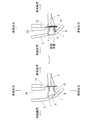
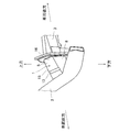
- 1 is a perspective view showing a front structure of a vehicle according to an embodiment of the present invention. It is a side view which shows the front part structure of the vehicle of this embodiment. It is an explanatory view of an effect by a level difference in this embodiment, and is a side view of a front part structure of a vehicle. It is explanatory drawing of the effect by the 1st bead and 2nd bead in this embodiment, and is a top view of the front part structure of a vehicle. It is explanatory drawing of the effect by the 3rd bead in this embodiment, and is a perspective view of the front part structure of a vehicle. It is explanatory drawing of the effect by the 4th bead in this embodiment, and is a bottom view of the front part structure of a vehicle.
- FIG. 1 is a perspective view showing a front structure of a vehicle according to an embodiment of the present invention.
- FIG. 2 is a side view showing the front structure of the vehicle of this embodiment. 1 and 2 show the crash box 1 and the front bumper beam 2 in the front left part of the vehicle.
- FIG. 2 is a view of the vicinity of the crash box 1 from a position slightly below the right side of the crash box 1.
- a crash box 1 is fastened by bolts or the like to front ends of side members 3 extending in the vehicle front-rear direction on both sides in the vehicle width direction.
- the crash box 1 is a tubular member having a space inside, and is provided with a front bumper beam 2 extending in the vehicle width direction so as to connect the tips of the crash boxes 1 on both sides in the vehicle width direction.
- Both end portions of the front bumper beam 2 in the vehicle width direction have inclined portions 2a that are inclined rearward as they go outward in the vehicle width direction end portion.
- the crash box 1 includes an upper wall 5 (a wall portion on the other side in the vehicle vertical direction) inclined downward toward the front of the vehicle, and a lower wall 6 extending substantially horizontally (a wall on the one side in the vehicle vertical direction). Section) and left and right side walls 7 and 8 extending in the vertical direction, and has a rectangular vertical cross section and a trapezoidal side view.
- the rear end of the crash box 1 is connected to the lamp support 9 extending in the vehicle vertical direction at the front end of the side member 3, and the rear end of the upper wall 5 is located at a position facing the upper end of the side member 3 of the lamp support 9.
- the lower wall 6 is connected to a portion of the lamp support 9 located below the lower wall of the side member 3.
- the lower end of the lamp support 9 is connected to a subframe (not shown).
- the front end of the crush box 1 is connected to the inclined portion 2a at the end of the front bumper beam 2, and the side wall 7 positioned inside the crash box 1 in the vehicle width direction has a side wall 8 positioned outside in the vehicle width direction. On the other hand, it extends to the front of the vehicle. As described above, the crash box 1 connects the front bumper beam 2 and the side member 3 via the lamp support 9 in this embodiment.
- a vehicle-mounted device for example, a radiator 20 is arranged behind the front bumper beam 2 at a distance in the front-rear direction behind the front bumper beam 2 (a position facing the rear surface).
- the front end of the radiator 20 is located in front of the front end of the side member 3.
- a vehicle with a high vehicle height such as an SUV vehicle is assumed, and the side member 3 is arranged at a relatively high position.
- the vertical position of the front bumper beam 2 is offset below the vertical position of the side member 3 so that the front bumper beam 2 can receive a collision load when the vehicle collides with a vehicle having a low vehicle height. That is, the lower end of the front bumper beam 2 is arranged below the lower wall of the side member 3.
- the crash box 1 connecting the side member 3 and the front bumper beam 2 is offset downward with respect to the side member 3 (the lower wall 6 is located below the side member 3) as described above.
- the term “the crash box 1 is offset with respect to the side member 3” means that the rear end of the crash box 1 is offset with respect to the front end of the side member 3.
- the crush box 1 of the present embodiment includes a step 10 on the lower wall 6, a first bead 11 on the upper wall 5, a second bead 14 on the right side wall 7 on the inner side in the vehicle width direction, and a third bead on the lower wall 6. And a fourth bead 13 on the upper wall 5.
- the step 10 is provided at an intermediate portion in the front-rear direction of the lower wall 6 and is formed so as to extend over the entire lower wall 6 in the vehicle width direction.
- the step 10 is located slightly behind the front end of the side wall 8 on the outer side in the vehicle width direction.
- the lower wall 6 is formed such that the vehicle front side portion of the step 10 is located, for example, several mm to several cm above.
- the first bead 11 and the second bead 14 are formed on the front side of the vehicle with respect to the step 10.
- the upper wall 5 and the side wall 7 on the inner side in the vehicle width direction are projected outward by, for example, several mm to several cm. It is a convex bead.
- the first bead 11 extends in the entire vertical direction on the side wall 7 of the crush box 1, and the second bead 14 extends in the entire vehicle width direction on the upper wall 5.
- the first bead 11 is located at a position in front of the vehicle with respect to the front end of the side wall 7 located on the vehicle width direction inner side of the crash box 1 and on the vehicle width direction outer side.
- the second bead 14 is located at the same position as the first bead 11 in the vehicle front-rear direction of the upper wall 5. Further, the first bead 11 and the second bead 14 are formed so as to be continuous with each other, and also project outwardly at the ridge line portion 15 between the upper wall 5 and the side wall 7.
- the third bead 12 is a convex bead that extends toward the front of the vehicle from the rear end portion of the crash box 1 on the lower wall 6, that is, the connection position with the side member 3, and projects downward by, for example, several mm to several cm.
- Two third beads 12 are provided on the lower wall 6 at intervals in the vehicle width direction, and extend to a position rearward of the vehicle with respect to the step 10. Further, the front end of the third bead 12 is located in front of the radiator 20.
- the fourth bead 13 is provided on the upper wall 5, extends in the entire vehicle width direction at a position in the vehicle front-rear direction that is substantially the same as the tip of the third bead 12, and is, for example, several mm to several cm inward (downward). It is a concave bead that dents in. Further, the fourth bead 13 is formed so as to be recessed inward also at the ridge line portion 15 between the upper wall 5 and the right side wall 7 and the ridge line portion 16 between the upper wall 5 and the left side wall 8.
- the effects of the step 10, the first bead 11, the second bead 14, the third bead 12, and the fourth bead 13 provided in the crash box 1 will be described with reference to FIGS. 3 to 6.
- FIG. 6 also shows a state in which a collision load is applied from the front.
- the front side is in the same manner as in a frontal collision.
- the crash box 1 When a collision load is applied to the bumper beam 2 toward the rear of the vehicle, the crash box 1 is pressed so as to dive under the side member 3 so that a moment for lifting the front end portion of the side member 3 upward is applied. There is a risk of giving.
- the moment acts on the side member 3, the load absorbing performance of the side member 3 deteriorates.
- the step 10 by providing the step 10 on the lower wall 6 of the crash box 1, when a collision load acts on the front bumper beam 2 rearward, the step 10 causes the crash box 1 to move. Since the lower wall 6 is crushed and the collision load transmitted from the lower portion of the crash box 1 to the side member 3 is absorbed, it is possible to suppress the generation of a moment that lifts the front end portion of the side member 3 upward.
- a bead extending in the vehicle width direction may be provided on the lower wall of the crash box 1 instead of the step 10. Since the lower wall 6 is provided with the bead extending in the vehicle width direction in this manner, the lower wall 6 of the crash box 1 is crushed at the position of this bead at the time of a frontal collision, and the collision is transmitted from the lower portion of the crash box 1 to the side member 3. Although the load is absorbed, the lower wall 6 of the crush box 1 is convexly deformed at the bead position, and a moment that lifts the front end portion of the side member 3 upward is generated. Therefore, in the present embodiment, the bead is not used. There are steps.
- the cross-sectional area of the crash box 1 on the vehicle front side of the step 10 is formed. Is smaller than the cross-sectional area of the rear side of the vehicle, the crush box 1 can be more reliably crushed from the front, and the deformation of the crush box 1 can be stabilized.
- the end portion of the front bumper beam 2 has a shape inclined rearward toward the outer side in the vehicle width direction, and the side walls 7 and 8 of the crash box 1 are short on the outer side in the vehicle width direction.
- the inner side in the vehicle width direction is formed to be long.
- the side wall 7 is deformed before the step 10 at the time of a frontal collision, It is possible to prevent the collision load input to the step 10 from tilting in the vehicle width direction. Since the second bead 14 is provided on the upper wall 5, the left and right lengths of the upper wall 5 and the side walls 7 and 8 are substantially the same due to the first bead 11 and the second bead 14 at the time of a frontal collision. It will be crushed.
- the second bead 14 in parallel with the step 10, it is possible to further prevent the collision load input to the step 10 from tilting in the vehicle width direction.
- the first bead 11 and the second bead 14 are connected to each other, and the bead is also provided over the ridge line portion 15 between the upper wall 5 and the side wall 7, so that the ridge line portion 15 is stably deformed. be able to.
- the rear wall 6 of the lower wall 6 of the crash box 1 is provided with a third bead 12 extending in the vehicle front-rear direction by providing the lower wall 6 of the crash box 1 with a large collision load. It is possible to suppress the deformation such that the side member 3 is broken, and it is possible to suppress the occurrence of a moment that lifts the front end portion of the side member 3 upward.
- the third bead 12 extends to the front of the radiator 20, the portion provided with the third bead 12 is less likely to be crushed rearward in a light collision, and thus the radiator 20 or the like is not easily crushed. It is possible to avoid damaging the vehicle-mounted device.
- a fourth bead 13 extending in the left-right direction is provided on the upper wall 5 of the crash box 1 at a front-rear position substantially the same as the front end portion of the third bead 12, so that a light collision occurs.
- the upper wall 5 is positively deformed at the position of the fourth bead 13, and a position behind the fourth bead 13 is formed. Can be suppressed. As a result, it is possible to further suppress the deformation of the portion behind the fourth bead 13 in the event of a light collision, and avoid damaging the vehicle-mounted devices such as the radiator 20.
- the second bead 14 provided on the upper wall 5 of the crush box 1 is a convex bead
- the fourth bead 13 is a concave bead, which protrude in mutually opposite directions.
- the upper wall 5 of the crash box 1 is deformed and crushed alternately in the vertical direction at the time of a frontal collision, so that the deformation of the crash box 1 can be more stabilized.
- the present invention is not limited to the above embodiment.
- the first bead 11, the second bead 14, the third bead 12, and the fourth bead 13 described above if at least the step 10 is provided, the beads 11, 12, 13, 14 are formed. May be appropriately adopted.
- the front bumper beam 2 is located below the side member 3 and the crash box 1 is offset downward from the side member 3, but the front bumper beam 2 is located above the side member 3.
- the crush box 1 is located at the upper position and the crush box 1 is offset upward with respect to the side member 3 (the upper wall 5 is positioned above the upper end of the side member 3), the crush box is turned upside down with respect to the above embodiment.
- the steps 10 and the beads 11, 12, 13, and 14 may be formed on the surface 1.
- the present invention is described as a crush box that is trapezoidal in side view, but can be applied to a rectangular crush box in side view.
Landscapes
- Engineering & Computer Science (AREA)
- Mechanical Engineering (AREA)
- Body Structure For Vehicles (AREA)
Abstract
車両のサイドメンバ3の前端部と、サイドメンバ3に対して下方にオフセットして配置されたフロントバンパビーム2とを車両前後方向に延びて接続するクラッシュボックス1を有する車両の前部構造であって、クラッシュボックス1の上壁5は車両前方に向かって下方に傾斜し、クラッシュボックス1の下壁6はサイドメンバ3の下壁より下方に位置して水平方向に延び、クラッシュボックス1の下壁6に車幅方向に延び車両後方側の部位よりも車両前方側の部位が上方に位置する段差10を設けた。
Description
本発明は、車両の前部構造に関し、衝突時における衝撃吸収構造に関する。
従来から、車両の衝突時に発生する衝撃荷重を吸収するために、フロントバンパビームをサイドメンバの前端にクラッシュボックスを介して設ける構成が知られている。このような構成では、車両の衝突により衝撃を受けた場合にはクラッシュボックスが圧縮するように変形して衝撃を吸収する構造となっている。
ところで、SUV車のように車高の高い車両では、サイドメンバに対してフロントバンパビームを下方に配置することがある。このように、サイドメンバとフロントバンパビームの高さが異なる場合、特許文献1のようにクラッシュボックスを上下方向に傾斜させる構造が知られている。
ところで、SUV車のように車高の高い車両では、サイドメンバに対してフロントバンパビームを下方に配置することがある。このように、サイドメンバとフロントバンパビームの高さが異なる場合、特許文献1のようにクラッシュボックスを上下方向に傾斜させる構造が知られている。
このように車高の高い車両において、クラッシュボックスを上下方向に傾斜させる方法の他に、サイドメンバに対してクラッシュボックスを上下方向にオフセットさせることで、フロントバンパビームとサイドメンバの高さを異ならせる方法が考えられる。しかし、この場合、サイドメンバとクラッシュボックスの位置がずれているため、フロントバンパビームに衝突荷重が作用した際に、サイドメンバに対してサイドメンバの前端部が持ち上がるようなモーメントが発生し、サイドメンバがクラッシュボックスより先に変形し、サイドメンバによるエネルギー吸収効率が悪化する虞がある。
本発明はこのような問題点を解決するためになされたもので、その目的とするところは、サイドメンバに対して上下方向にオフセットして配置されたクラッシュボックスを有する車両において、前突時にサイドメンバに発生するモーメントを抑えつつクラッシュボックスを安定して圧縮変形させ荷重吸収性能を向上させる車両の前部構造を提供することにある。
上記の目的を達成するために、本発明は、車幅方向の両側で車両前後方向に延びるサイドメンバと、前記サイドメンバの車両前方で車幅方向に延び、前記サイドメンバに対して車両上下方向一方側にオフセットして配置されるフロントバンパビームと、車両前後方向に延びて前記サイドメンバと前記フロントバンパビームとを接続するクラッシュボックスと、を有する車両の前部構造であって、前記クラッシュボックスの前記一方側の壁部が、前記サイドメンバの前記一方側の壁部より前記一方側に位置し、前記クラッシュボックスの前記一方側の壁部に、車幅方向に延びる段差を備える。
これにより、車両前突時のように、フロントバンパビームが後方に荷重を受けてクラッシュボックスが変形して荷重を吸収する際に、クラッシュボックスの一方側の壁部が他方側の壁部に向かって大きく上下方向に屈曲するような変形を抑制して、クラッシュボックスを安定して後方に圧縮変形させることができる。
好ましくは、フロントバンパビームの端部は、車幅方向外側へ向かうにつれて車両後方に傾斜した傾斜部を有し、クラッシュボックスは、前記傾斜部に接続されており、クラッシュボックスの車幅方向内側の側壁に、段差より車両前方側の位置で上下方向に延びる第1のビードを備えるとよい。
好ましくは、フロントバンパビームの端部は、車幅方向外側へ向かうにつれて車両後方に傾斜した傾斜部を有し、クラッシュボックスは、前記傾斜部に接続されており、クラッシュボックスの車幅方向内側の側壁に、段差より車両前方側の位置で上下方向に延びる第1のビードを備えるとよい。
これにより、車両前突時のように、フロントバンパビームが後方に荷重を受けた際に、段差より前に位置する第1のビードの位置でクラッシュボックスの車幅方向内側の側壁を変形させる。これにより、クラッシュボックスの左右の側壁の長さが異なっていても、クラッシュボックスが左右に傾かないように圧縮変形させることができる。
好ましくは、クラッシュボックスの車両上下方向他方側の壁部に、車幅方向に延びる第2のビードを備え、前記第2のビードは、第1のビードと車両前後方向で同一の位置に設けられるとよい。
好ましくは、クラッシュボックスの車両上下方向他方側の壁部に、車幅方向に延びる第2のビードを備え、前記第2のビードは、第1のビードと車両前後方向で同一の位置に設けられるとよい。
これにより、側壁に形成された第1のビードと、車両上下方向他方側の壁部に形成された第2のビードによって、クラッシュボックスの変形位置を安定させることができる。
好ましくは、第2のビードは、第1のビードと連続して形成されているとよい
これにより、フロントバンパビームが後方に荷重を受けた際に、互いに同一の前後位置にある第1のビードと第2のビードによって、クラッシュボックスの変形位置を安定させることができる。また、第1のビードと第2のビードが、側壁と車両上下方向他方側の壁部との間の稜線部を横切るように形成されるので、稜線部において変形し易くし、クラッシュボックスの変形位置を第1のビードの前後位置でより安定させることができる。
好ましくは、第2のビードは、第1のビードと連続して形成されているとよい
これにより、フロントバンパビームが後方に荷重を受けた際に、互いに同一の前後位置にある第1のビードと第2のビードによって、クラッシュボックスの変形位置を安定させることができる。また、第1のビードと第2のビードが、側壁と車両上下方向他方側の壁部との間の稜線部を横切るように形成されるので、稜線部において変形し易くし、クラッシュボックスの変形位置を第1のビードの前後位置でより安定させることができる。
好ましくは、クラッシュボックスの一方側の壁部に、当該一方側の壁部の後端から段差よりも車両後方の位置まで車両前方に延びる第3のビードを備えるとよい。
これにより、第3のビードが設けられるクラッシュボックスの後部が、第3のビードが設けられない前部よりも潰れにくくなる。したがって、軽衝突時において、第3のビードの前端より後方を保護することができる。
これにより、第3のビードが設けられるクラッシュボックスの後部が、第3のビードが設けられない前部よりも潰れにくくなる。したがって、軽衝突時において、第3のビードの前端より後方を保護することができる。
好ましくは、フロントバンパビームの後方には、前端がサイドメンバの前端より前方に位置する車載機器が設けられ、第3のビードの前端は、前記車載機器の前端よりも前方に位置するとよい。
これにより、軽衝突時において、クラッシュボックスの前部が潰れても第3のビードが設けられる部位は潰れにくく、車載機器を保護することができる。
これにより、軽衝突時において、クラッシュボックスの前部が潰れても第3のビードが設けられる部位は潰れにくく、車載機器を保護することができる。
好ましくは、クラッシュボックスの車両上下方向他方側の壁部には、第3のビードの前端と車両前後方向で同一の位置に、車幅方向に延びる第4のビードが備えられるとよい。
これにより、軽衝突時において、クラッシュボックスの上壁と下壁を第3のビードの前端部及び第4のビードの前後位置まで安定した形状で圧縮変形させることができ、第4のビードより後方の部位の変形を抑制することができる。
これにより、軽衝突時において、クラッシュボックスの上壁と下壁を第3のビードの前端部及び第4のビードの前後位置まで安定した形状で圧縮変形させることができ、第4のビードより後方の部位の変形を抑制することができる。
好ましくは、第4のビードは、クラッシュボックスの車両上下方向他方側の壁部に設けられた、段差より車両前方側の位置で車幅方向に延びる第2のビードと逆方向に突出しているとよい。
これにより、前突時にクラッシュボックスが第4のビードまで潰れた際に、第2のビード及び第4のビードが設けられている車両上下方向他方側の壁部が、上下方向に互い違いに変形して潰れるので、当該壁部が上下方向の一方に大きく曲がることを抑制し、モーメントの発生を抑制することができる。
これにより、前突時にクラッシュボックスが第4のビードまで潰れた際に、第2のビード及び第4のビードが設けられている車両上下方向他方側の壁部が、上下方向に互い違いに変形して潰れるので、当該壁部が上下方向の一方に大きく曲がることを抑制し、モーメントの発生を抑制することができる。
好ましくは、クラッシュボックスの車両上下方向他方側の壁部は、車両前方側へ向かうにつれて一方側に傾斜しており、一方側の壁部は水平に延びているとよい。
これにより、車両前突時のように、フロントバンパビームが後方に荷重を受けてクラッシュボックスが変形して荷重を吸収する際に、クラッシュボックスが大きく上下方向に屈曲するような変形を抑制して、クラッシュボックスを安定して後方に圧縮変形させることができる。
これにより、車両前突時のように、フロントバンパビームが後方に荷重を受けてクラッシュボックスが変形して荷重を吸収する際に、クラッシュボックスが大きく上下方向に屈曲するような変形を抑制して、クラッシュボックスを安定して後方に圧縮変形させることができる。
本発明の車両の前部構造によれば、サイドメンバに対して車両上下方向一方側にオフセットして配置されたフロントバンパビームが後方に向けて荷重を受けても、クラッシュボックスを安定して後方に圧縮変形させることができるので、クラッシュボックスによる荷重吸収性能を向上させることができる。
以下、図面に基づき本発明の実施形態について説明する。
図1は、本発明の実施形態の車両の前部構造を示す斜視図である。図2は、本実施形態の車両の前部構造を示す側面図である。なお、図1及び図2は、車両の前左部におけるクラッシュボックス1及びフロントバンパビーム2を図示している。また、図2は、クラッシュボックス1の右方のわずかに下方の位置からクラッシュボックス1付近を視た図である。
図1は、本発明の実施形態の車両の前部構造を示す斜視図である。図2は、本実施形態の車両の前部構造を示す側面図である。なお、図1及び図2は、車両の前左部におけるクラッシュボックス1及びフロントバンパビーム2を図示している。また、図2は、クラッシュボックス1の右方のわずかに下方の位置からクラッシュボックス1付近を視た図である。
図1、2に示すように、車両の車幅方向両側において車両前後方向に延在するサイドメンバ3の前端部には、クラッシュボックス1がボルト等によって締結されている。クラッシュボックス1は、内部に空間を有する筒状の部材であり、車幅方向両側のクラッシュボックス1の先端を繋ぐように車幅方向に延びるフロントバンパビーム2が設けられている。フロントバンパビーム2の車幅方向両端部は、車幅方向端部外側に向うにつれて後方に傾斜した傾斜部2aを有している。
なお、図1、2においては、車両左方のサイドメンバ3及びクラッシュボックス1を示しているが、図示しない車両右方のサイドメンバ及びクラッシュボックス1も左右対称の形状(すなわち「左」と「右」を置き換えた形状)となっているため、以下、車両左方の構造のみを説明する。
本実施形態では、クラッシュボックス1は、車両前方に向かって下方に傾斜した上壁5(車両上下方向他方側の壁部)と、略水平方向に延びる下壁6(車両上下方向一方側の壁部)と、上下方向に延びる左右の側壁7、8を備えており、縦断面が矩形、側面視が台形状になっている。
本実施形態では、クラッシュボックス1は、車両前方に向かって下方に傾斜した上壁5(車両上下方向他方側の壁部)と、略水平方向に延びる下壁6(車両上下方向一方側の壁部)と、上下方向に延びる左右の側壁7、8を備えており、縦断面が矩形、側面視が台形状になっている。
クラッシュボックス1の後端は、サイドメンバ3の前端で車両上下方向に延びるランプサポート9に接続されており、上壁5の後端がランプサポート9のサイドメンバ3の上端部に対向する箇所に、下壁6がランプサポート9のサイドメンバ3の下壁よりも下方に位置する箇所に接続されている。なお、ランプサポート9の下端は、図示しないサブフレームに接続されている。
また、クラッシュボックス1の前端は、フロントバンパビーム2の端部の傾斜部2aに接続されており、クラッシュボックス1の車幅方向内側に位置する側壁7は、車幅方向外側に位置する側壁8に対し、車両前方まで延在している。
上記のように、クラッシュボックス1は、フロントバンパビーム2とサイドメンバ3とを、本実施形態ではランプサポート9を介して接続している。
上記のように、クラッシュボックス1は、フロントバンパビーム2とサイドメンバ3とを、本実施形態ではランプサポート9を介して接続している。
図5に示すように、フロントバンパビーム2の後方には車載機器、例えばラジエータ20がフロントバンパビーム2の後方(後面と対向する位置)に前後方向に間隔をおいて配置されている。ラジエータ20は、その前端がサイドメンバ3の前端より前方に位置している。
なお、本実施形態では、SUV車のように車高が高い車両を想定しており、サイドメンバ3が比較的高い位置に配置されている。一方、フロントバンパビーム2の上下位置は、例えば車高の低い車両と衝突した際に、衝突荷重をフロントバンパビーム2で受けることができるよう、サイドメンバ3の上下位置よりも下方にオフセットした位置、すなわちフロントバンパビーム2の下端がサイドメンバ3の下壁よりも下方に位置するように配置されている。したがって、サイドメンバ3とフロントバンパビーム2とを接続するクラッシュボックス1は、上記のようにサイドメンバ3に対して下方にオフセット(下壁6がサイドメンバ3より下方に位置)している。なお、ここで言うクラッシュボックス1がサイドメンバ3に対してオフセットしているとは、クラッシュボックス1の後端がサイドメンバ3の前端に対してオフセットしていることを言う。
なお、本実施形態では、SUV車のように車高が高い車両を想定しており、サイドメンバ3が比較的高い位置に配置されている。一方、フロントバンパビーム2の上下位置は、例えば車高の低い車両と衝突した際に、衝突荷重をフロントバンパビーム2で受けることができるよう、サイドメンバ3の上下位置よりも下方にオフセットした位置、すなわちフロントバンパビーム2の下端がサイドメンバ3の下壁よりも下方に位置するように配置されている。したがって、サイドメンバ3とフロントバンパビーム2とを接続するクラッシュボックス1は、上記のようにサイドメンバ3に対して下方にオフセット(下壁6がサイドメンバ3より下方に位置)している。なお、ここで言うクラッシュボックス1がサイドメンバ3に対してオフセットしているとは、クラッシュボックス1の後端がサイドメンバ3の前端に対してオフセットしていることを言う。
本実施形態のクラッシュボックス1は、下壁6に段差10を備えるとともに、上壁5に第1のビード11、車幅方向内側の右側壁7に第2のビード14、下壁6に第3のビード12、上壁5に第4のビード13を備えている。
段差10は、下壁6の前後方向中間部に設けられ、下壁6を車幅方向全域に亘って延びるように形成されている。本実施形態では、段差10は、車幅方向外側の側壁8の前端より若干後方に位置している。下壁6は、段差10の車両後方側の部位よりも車両前方側の部位が例えば数mm~数cm程度上方に位置するように形成されている。
段差10は、下壁6の前後方向中間部に設けられ、下壁6を車幅方向全域に亘って延びるように形成されている。本実施形態では、段差10は、車幅方向外側の側壁8の前端より若干後方に位置している。下壁6は、段差10の車両後方側の部位よりも車両前方側の部位が例えば数mm~数cm程度上方に位置するように形成されている。
第1のビード11及び第2のビード14は、段差10よりも車両前方に形成されており、上壁5及び車幅方向内側の側壁7を例えば数mm~数cm程度外方に突出させた凸型のビードである。第1のビード11は、クラッシュボックス1の側壁7において上下方向全域に延び、第2のビード14は上壁5において車幅方向全域に延びている。第1のビード11は、クラッシュボックス1の車幅方向内側に位置する側壁7の、車幅方向外側に位置する側壁8の前端よりも車両前方の箇所に位置している。第2のビード14は、上壁5の車両前後方向において第1のビード11と同一の箇所に位置している。また、第1のビード11と第2のビード14は、互いに連続するように形成されており、上壁5と側壁7の間の稜線部15においても外方に突出している。
第3のビード12は、下壁6においてクラッシュボックス1の後端部、即ちサイドメンバ3との接続位置から車両前方に延び例えば数mm~数cm程度下方に突出した凸型のビードである。第3のビード12は、下壁6に車幅方向に間隔をおいて2つ設けられ、段差10よりも車両後方の位置まで延びている。また、第3のビード12の前端は、ラジエータ20よりも前方に位置している。
第4のビード13は、上壁5に設けられ、第3のビード12の先端と略同一の車両前後方向の位置で車幅方向全域に延び、例えば数mm~数cm程度内方(下方)に凹む凹型のビードである。また、第4のビード13は、上壁5と右側壁7の間の稜線部15、及び上壁5と左側壁8の間の稜線部16においても内方に凹むように形成されている。
次に、図3~6を用いて、クラッシュボックス1に設けた段差10、第1のビード11、第2のビード14、第3のビード12、第4のビード13の効果について説明する。なお、図3~5において、左側の図が衝突荷重を受けていない状態、右側の図が前方より衝突荷重を受けた状態を示している。また、図6も、前方より衝突荷重を受けた状態を示している。
次に、図3~6を用いて、クラッシュボックス1に設けた段差10、第1のビード11、第2のビード14、第3のビード12、第4のビード13の効果について説明する。なお、図3~5において、左側の図が衝突荷重を受けていない状態、右側の図が前方より衝突荷重を受けた状態を示している。また、図6も、前方より衝突荷重を受けた状態を示している。
本実施形態のように上下位置が異なるサイドメンバ3とフロントバンパビーム2とを接続するクラッシュボックス1が、サイドメンバ3に対して下方にオフセットしている場合には、前突時のようにフロントバンパビーム2に車両後方に向けて衝突荷重が作用した際に、クラッシュボックス1がサイドメンバ3の下方に潜りこむように押圧されることによって、サイドメンバ3の前端部を上方に持ち上げるようなモーメントを与えてしまう虞がある。このように、サイドメンバ3にモーメントが作用するとサイドメンバ3の荷重吸収性能が低下してしまう。
しかしながら図3に示すように、本実施形態ではクラッシュボックス1の下壁6に段差10を設けることで、フロントバンパビーム2に後方に衝突荷重が作用した場合に、当該段差10によってクラッシュボックス1の下壁6が潰れ、クラッシュボックス1の下部からサイドメンバ3に伝達する衝突荷重が吸収されるため、サイドメンバ3の前端部を上方に持ち上げるようなモーメントの発生を抑えることができる。
なお、クラッシュボックス1の下壁に段差10ではなく、車幅方向に延びるビードを設けることが考えられる。このように下壁6に車幅方向に延びるビードを備えることで、前突時にこのビードの位置でクラッシュボックス1の下壁6が潰れて、クラッシュボックス1の下部からサイドメンバ3に伝達する衝突荷重を吸収するものの、ビードの位置でクラッシュボックス1の下壁6が凸変形を起こし、サイドメンバ3の前端部を上方に持ち上げるようなモーメントが発生してしまうため、本実施形態ではビードではなく段差としている。
また、段差10を、下壁6の段差10より車両前方側の部位が車両後方側の部位よりも上方に位置するように形成することにより、クラッシュボックス1の段差10より車両前方側の断面積が車両後方側の断面積より小さくなるので、クラッシュボックス1をより確実に前方から潰すことができ、クラッシュボックス1の変形を安定させることができる。
図4に示すように、フロントバンパビーム2の端部は、車幅方向外側に向かって後方に傾斜した形状になっており、クラッシュボックス1の側壁7、8は、車幅方向外側が短く、車幅方向内側が長く形成されている。したがって、フロントバンパビーム2に対し車両後方に衝突荷重が作用した場合、クラッシュボックス1の段差10に車幅方向に傾いた衝突荷重が入力されてしまい、クラッシュボックス1が前後方向に安定して圧縮変形せずに荷重を十分に吸収することが困難になる虞がある。
図4に示すように、フロントバンパビーム2の端部は、車幅方向外側に向かって後方に傾斜した形状になっており、クラッシュボックス1の側壁7、8は、車幅方向外側が短く、車幅方向内側が長く形成されている。したがって、フロントバンパビーム2に対し車両後方に衝突荷重が作用した場合、クラッシュボックス1の段差10に車幅方向に傾いた衝突荷重が入力されてしまい、クラッシュボックス1が前後方向に安定して圧縮変形せずに荷重を十分に吸収することが困難になる虞がある。
本実施形態では、クラッシュボックス1の車幅方向内側の側壁7の段差10よりも前方の箇所に第1のビード11を設けることで、前突時に段差10より前で側壁7を変形させて、段差10に入力される衝突荷重が車幅方向に傾くことを抑制することができる。また、上壁5に第2のビード14を設けたので、前突時に第1のビード11及び第2のビード14により上壁5及び側壁7、8が左右の長さが略同一になるまで潰れるようになる。このとき、第2のビード14を段差10と平行に延ばすことにより、段差10に入力される衝突荷重が車幅方向に傾くことをより抑制することができる。特に、第1のビード11と第2のビード14を連結させ、上壁5と側壁7との間の稜線部15にもビードが亘って設けられるので、この稜線部15を安定して変形させることができる。
図5に示すように、クラッシュボックス1の下壁6に車両前後方向に延びる第3のビード12が設けられることで大きな衝突荷重が入力された際に、クラッシュボックス1の下壁6の後部が折れるように変形することを抑制し、サイドメンバ3の前端部を上方に持ち上げるようなモーメントの発生を抑えることができる。
なお、図5に示すように、第3のビード12がラジエータ20より前方まで延びているので、軽衝突時において第3のビード12が設けられた部位が後方に潰れにくくなり、ラジエータ20等の車載機器を破損させてしまうことを回避することができる。
なお、図5に示すように、第3のビード12がラジエータ20より前方まで延びているので、軽衝突時において第3のビード12が設けられた部位が後方に潰れにくくなり、ラジエータ20等の車載機器を破損させてしまうことを回避することができる。
また、図6に示すように、クラッシュボックス1の上壁5に左右方向に延びる第4のビード13を、第3のビード12の前端部と略同一の前後位置に設けたので、軽衝突時にクラッシュボックス1の下壁6が第3のビード12の前端部まで潰れた際に、上壁5を第4のビード13の位置で積極的に変形させ、第4のビード13よりも後方の箇所が潰れることを抑制することができる。これにより、軽衝突時に第4のビード13より後方の部位の変形を更に抑制し、ラジエータ20等の車載機器を破損させてしまうことを回避することができる。
また、クラッシュボックス1の上壁5に設けられた第2のビード14は凸型のビードであり、第4のビード13は凹型のビードであって、互いに逆方向に突出している。これにより、前突時にクラッシュボックス1の上壁5が上下方向に互い違いに変形して潰れるので、クラッシュボックス1の変形をより安定させることができる。
本願発明は、上記実施形態に限定するものではない。例えば、上記の段差10、第1のビード11、第2のビード14、第3のビード12、第4のビード13については、少なくとも段差10が設けられていればビード11、12、13、14については、適宜採用してよい。また、上記実施形態では、サイドメンバ3に対しフロントバンパビーム2が下方に位置し、クラッシュボックス1がサイドメンバ3に対し下方にオフセットしているが、サイドメンバ3に対しフロントバンパビーム2が上方に位置し、クラッシュボックス1をサイドメンバ3に対し上方にオフセットさせる(上壁5をサイドメンバ3の上端より上方に位置させる)場合には、上記実施形態に対して上下を逆転させてクラッシュボックス1に段差10や各ビード11、12、13、14を形成すればよい。
本願発明は、上記実施形態に限定するものではない。例えば、上記の段差10、第1のビード11、第2のビード14、第3のビード12、第4のビード13については、少なくとも段差10が設けられていればビード11、12、13、14については、適宜採用してよい。また、上記実施形態では、サイドメンバ3に対しフロントバンパビーム2が下方に位置し、クラッシュボックス1がサイドメンバ3に対し下方にオフセットしているが、サイドメンバ3に対しフロントバンパビーム2が上方に位置し、クラッシュボックス1をサイドメンバ3に対し上方にオフセットさせる(上壁5をサイドメンバ3の上端より上方に位置させる)場合には、上記実施形態に対して上下を逆転させてクラッシュボックス1に段差10や各ビード11、12、13、14を形成すればよい。
本発明は、側面視で台形状になっているクラッシュボックスとしているが、側面視で矩形のクラッシュボックスに適用することもできる。
1 クラッシュボックス
2 フロントバンパビーム
2a 傾斜部
3 サイドメンバ
5 上壁
7 側壁
6 下壁
10 段差
10 段差
11 第1のビード
12 第3のビード
13 第4のビード
14 第2のビード
20 ラジエータ(車載機器)
2 フロントバンパビーム
2a 傾斜部
3 サイドメンバ
5 上壁
7 側壁
6 下壁
10 段差
10 段差
11 第1のビード
12 第3のビード
13 第4のビード
14 第2のビード
20 ラジエータ(車載機器)
Claims (9)
- 車幅方向の両側で車両前後方向に延びるサイドメンバと、前記サイドメンバの車両前方で車幅方向に延び、前記サイドメンバに対して車両上下方向一方側にオフセットして配置されるフロントバンパビームと、車両前後方向に延びて前記サイドメンバと前記フロントバンパビームとを接続するクラッシュボックスと、を有する車両の前部構造であって、
前記クラッシュボックスの前記一方側の壁部が、前記サイドメンバの前記一方側の壁部より前記一方側に位置し、
前記クラッシュボックスの前記一方側の壁部に、車幅方向に延びる段差を備えたことを特徴とする車両の前部構造。 - 前記フロントバンパビームの端部は、車幅方向外側へ向かうにつれて車両後方に傾斜した傾斜部を有し、
前記クラッシュボックスは、前記傾斜部に接続されており、
前記クラッシュボックスの車幅方向内側の側壁に、前記段差より車両前方側の位置で上下方向に延びる第1のビードを備えたことを特徴とする請求項1に記載の車両の前部構造。 - 前記クラッシュボックスの車両上下方向他方側の壁部に、車幅方向に延びる第2のビードを備え、
前記第2のビードは、前記第1のビードと車両前後方向で同一の位置に設けられることを特徴とする請求項2に記載の車両の前部構造。 - 前記第2のビードは、前記第1のビードと連続して形成されていることを特徴とする請求項3に記載の車両の前部構造。
- 前記クラッシュボックスの前記一方側の壁部に、当該一方側の壁部の後端から前記段差よりも車両後方の位置まで車両前方に延びる第3のビードを備えたことを特徴とする請求項1から4のいずれか1項に記載の車両の前部構造。
- 前記フロントバンパビームの後方には、前端が前記サイドメンバの前端より前方に位置する車載機器が設けられ、
前記第3のビードの前端は、前記車載機器の前端よりも前方に位置することを特徴とする請求項5に記載の車両の前部構造。 - 前記クラッシュボックスの車両上下方向他方側の壁部には、前記第3のビードの前端と車両前後方向で同一の位置に、車幅方向に延びる第4のビードが備えられたことを特徴とする請求項6に記載の車両の前部構造。
- 前記第4のビードは、前記クラッシュボックスの車両上下方向他方側の壁部に設けられた、前記段差より車両前方側の位置で車幅方向に延びる第2のビードと逆方向に突出していることを特徴とする請求項7に記載の車両の前部構造。
- 前記クラッシュボックスの車両上下方向他方側の壁部は、車両前方側へ向かうにつれて前記一方側に傾斜しており、前記一方側の壁部は水平に延びている、ことを特徴とする請求項1から8のいずれか1項に記載の車両の前部構造。
Applications Claiming Priority (2)
| Application Number | Priority Date | Filing Date | Title |
|---|---|---|---|
| JP2018-245743 | 2018-12-27 | ||
| JP2018245743A JP2022043371A (ja) | 2018-12-27 | 2018-12-27 | 車両の前部構造 |
Publications (1)
| Publication Number | Publication Date |
|---|---|
| WO2020137102A1 true WO2020137102A1 (ja) | 2020-07-02 |
Family
ID=71128866
Family Applications (1)
| Application Number | Title | Priority Date | Filing Date |
|---|---|---|---|
| PCT/JP2019/040665 Ceased WO2020137102A1 (ja) | 2018-12-27 | 2019-10-16 | 車両の前部構造 |
Country Status (2)
| Country | Link |
|---|---|
| JP (1) | JP2022043371A (ja) |
| WO (1) | WO2020137102A1 (ja) |
Cited By (2)
| Publication number | Priority date | Publication date | Assignee | Title |
|---|---|---|---|---|
| CN112550193A (zh) * | 2020-12-03 | 2021-03-26 | 奇瑞汽车股份有限公司 | 吸能装置和车辆 |
| WO2022063174A1 (zh) * | 2020-09-24 | 2022-03-31 | 奇瑞汽车股份有限公司 | 车身前部结构和汽车 |
Citations (3)
| Publication number | Priority date | Publication date | Assignee | Title |
|---|---|---|---|---|
| JPH06211091A (ja) * | 1993-01-20 | 1994-08-02 | Nissan Motor Co Ltd | 車両のバンパー支持構造 |
| JP2011143793A (ja) * | 2010-01-13 | 2011-07-28 | Fuji Heavy Ind Ltd | 車両用緩衝装置 |
| US20160121830A1 (en) * | 2014-10-31 | 2016-05-05 | Benteler Automobil Technik Gmbh | Crashbox for a bumper system of a motor vehicle |
-
2018
- 2018-12-27 JP JP2018245743A patent/JP2022043371A/ja active Pending
-
2019
- 2019-10-16 WO PCT/JP2019/040665 patent/WO2020137102A1/ja not_active Ceased
Patent Citations (3)
| Publication number | Priority date | Publication date | Assignee | Title |
|---|---|---|---|---|
| JPH06211091A (ja) * | 1993-01-20 | 1994-08-02 | Nissan Motor Co Ltd | 車両のバンパー支持構造 |
| JP2011143793A (ja) * | 2010-01-13 | 2011-07-28 | Fuji Heavy Ind Ltd | 車両用緩衝装置 |
| US20160121830A1 (en) * | 2014-10-31 | 2016-05-05 | Benteler Automobil Technik Gmbh | Crashbox for a bumper system of a motor vehicle |
Cited By (2)
| Publication number | Priority date | Publication date | Assignee | Title |
|---|---|---|---|---|
| WO2022063174A1 (zh) * | 2020-09-24 | 2022-03-31 | 奇瑞汽车股份有限公司 | 车身前部结构和汽车 |
| CN112550193A (zh) * | 2020-12-03 | 2021-03-26 | 奇瑞汽车股份有限公司 | 吸能装置和车辆 |
Also Published As
| Publication number | Publication date |
|---|---|
| JP2022043371A (ja) | 2022-03-16 |
Similar Documents
| Publication | Publication Date | Title |
|---|---|---|
| US7540559B2 (en) | Rear structure of vehicle body | |
| JP4738474B2 (ja) | 車両用衝撃吸収部材 | |
| US8657364B2 (en) | Rear structure of a vehicle body | |
| US10421424B2 (en) | Vehicle front structure | |
| US20180154943A1 (en) | Vehicle engine compartment assembly | |
| US20150273996A1 (en) | Protection structure of battery module mounted in rear of vehicle body | |
| JP2018202897A (ja) | バンパビーム構造 | |
| JP6102870B2 (ja) | 車体前部構造 | |
| CN113263996B (zh) | 机动车保险杠 | |
| CN106687361A (zh) | 车身前部构造 | |
| JP5281630B2 (ja) | 車体後部構造 | |
| WO2020137102A1 (ja) | 車両の前部構造 | |
| JP2017039371A (ja) | 車体前部構造 | |
| JP2011143793A (ja) | 車両用緩衝装置 | |
| JP4865379B2 (ja) | 自動車用バンパ装置 | |
| JP2009090936A (ja) | 車両用インナパネル | |
| JP2019182151A (ja) | 車両骨格構造 | |
| JP7084326B2 (ja) | クラッシュボックス | |
| JP5630615B2 (ja) | 車両の車体構造 | |
| JP2013256162A (ja) | 車両前部構造 | |
| WO2020170578A1 (ja) | 車載部品支持構造 | |
| JP6737550B2 (ja) | 車両の前部構造 | |
| JP2021091306A (ja) | 車体後部構造 | |
| JP7691283B2 (ja) | 車両の衝撃吸収構造 | |
| JP7816634B2 (ja) | レーダの取付構造 |
Legal Events
| Date | Code | Title | Description |
|---|---|---|---|
| 121 | Ep: the epo has been informed by wipo that ep was designated in this application |
Ref document number: 19904481 Country of ref document: EP Kind code of ref document: A1 |
|
| NENP | Non-entry into the national phase |
Ref country code: DE |
|
| 122 | Ep: pct application non-entry in european phase |
Ref document number: 19904481 Country of ref document: EP Kind code of ref document: A1 |
|
| NENP | Non-entry into the national phase |
Ref country code: JP |