WO2020136867A1 - 作業ロボット - Google Patents
作業ロボット Download PDFInfo
- Publication number
- WO2020136867A1 WO2020136867A1 PCT/JP2018/048452 JP2018048452W WO2020136867A1 WO 2020136867 A1 WO2020136867 A1 WO 2020136867A1 JP 2018048452 W JP2018048452 W JP 2018048452W WO 2020136867 A1 WO2020136867 A1 WO 2020136867A1
- Authority
- WO
- WIPO (PCT)
- Prior art keywords
- work
- target
- sensor
- processing unit
- image
- Prior art date
- Legal status (The legal status is an assumption and is not a legal conclusion. Google has not performed a legal analysis and makes no representation as to the accuracy of the status listed.)
- Ceased
Links
Images




Classifications
-
- B—PERFORMING OPERATIONS; TRANSPORTING
- B25—HAND TOOLS; PORTABLE POWER-DRIVEN TOOLS; MANIPULATORS
- B25J—MANIPULATORS; CHAMBERS PROVIDED WITH MANIPULATION DEVICES
- B25J13/00—Controls for manipulators
- B25J13/08—Controls for manipulators by means of sensing devices, e.g. viewing or touching devices
Definitions
- This specification relates to a work robot.
- Work robots are widely used to promote automation and labor saving in factories and business establishments. Many work robots include an end effector that holds a work. In addition, many work robots use a camera to capture an image of a work target object, confirm the presence or absence of the work target object, the position and posture of the work target object, and the like before proceeding with the work. Patent Documents 1 and 2 disclose technical examples of this type of work robot.
- the tray-type sorting device of Patent Document 1 includes a plurality of trays that travel along a transport path, and a detection unit that identifies the presence or absence of a transported product on the tray.
- the unevenness is formed on the mounting surface of the tray, and the detection means identifies the presence or absence of the conveyed object by comparing the imaged data of the image of the tray with the reference image data regarding the color tone and the position obtained from the concave portion of the tray. To do.
- this method it is possible to detect the conveyed object without being affected by scratches caused by the rubbing of the conveyed object and the tray.
- the work transfer control device of Patent Document 2 includes a camera that captures a placement location where a work is placed, a detection device that detects the presence or absence and the position of the work based on a captured image acquired by the camera, and the position of the work.
- a control device for controlling the work holding robot based on the information According to this, it is said that it is possible to continuously convey more workpieces to the processing machine than in the past.
- Patent Documents 1 and 2 a determination method is used in which a work target is imaged using a camera and a predetermined work shape is searched on the acquired image data.
- the conventional determination method of searching the work shape may not be able to obtain sufficient reliability.
- each of the works is located in various directions when viewed from the camera and has a different distance from the camera.
- the two-dimensional shapes of a plurality of works differ on the image data, which may result in an erroneous determination.
- a configuration in which a sensor for detecting the presence or absence of a work is provided at a work path for carrying a work object or a work execution position has been conventionally used.
- the sensor may erroneously detect an accessory such as a handle provided on the work target as a work.
- restrictions on the mounting space of the sensor and an increase in cost become problems.
- This specification describes an end effector capable of holding a work to be placed on a work object, a moving device that moves the end effector, a camera that images the work object from above to obtain image data, and the image.
- Work including an image processing unit that searches the occupied area corresponding to the work on the data, and an image determination unit that determines the presence or absence of the work on the work target based on the search result of the image processing unit
- a robot is disclosed.
- a holding unit that holds a work to be placed on a work target
- an end effector having a sensor that detects the work held by the holding unit, and a moving device that moves the end effector
- a search processing unit that searches for the work on the work target using the sensor
- a sensor determination unit that determines the presence or absence of the work on the work target based on a search result of the search processing unit.
- a work robot including.
- the work target is highly reliable.
- the presence or absence of work on the object can be determined.
- the sensor included in the end effector is used to search for the work, so that the presence or absence of the work on the work target can be determined with high reliability.
- Configurations of Work Objects (91, 92) and Work Robot 1 The configurations of the work objects (91, 92) and work robot 1 in the first embodiment will be described with reference to FIGS. 1 to 7.
- the work robot 1 performs the placement work of placing the first work 93 on the first work target 91 and the placement work of placing the second work 94 on the second work target 92. Specifically, the work robot 1 inserts the works (93, 94) into the plurality of holes (911, 921) of the work target (91, 92) and arranges them.
- the work objects (91, 92) on which the works (93, 94) are arranged are transferred to another work robot in the downstream process and used for assembly work.
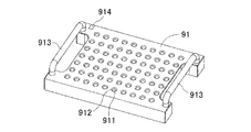
- the first work object 91 is a generally rectangular pallet member.
- the first work target 91 is carried in and out in a direction parallel to the long side thereof.
- a plurality of (70 in the example of FIG. 2) holes 911 having a circular cross section are provided on the upper surface of the first work object 91.
- the hole 911 is a planned position where the first work 93 is arranged.
- a countersink 912 is formed at the entrance of the hole 911 to facilitate the insertion of the first work 93.
- the first work 93 is an elongated pin made of iron having a circular cross section, and a part thereof is inserted into the hole 911.
- a handle 913 is provided on each of the two short sides of the first work target 91.
- An identification code 914 is attached near one corner (upper left corner in FIG. 2) of the first work target 91.
- the identification code 914 identifies the types of the first work target 91 and the first work 93.
- As the identification code 914 a barcode, a matrix type two-dimensional code, a number string, or the like is used.
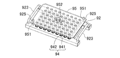
- the second work target object 92 is a rectangular pallet member having substantially the same size as the first work target object 91.
- the second work object 92 is carried in and out in a direction parallel to the long side thereof.
- a plurality of (54 in the example of FIG. 2) holes 921 having a circular cross section are provided on the upper surface of the second work object 92.
- the hole 921 is a planned position where the second work 94 is arranged.
- the second work 94 is an iron bolt including a head portion 941 and a shaft portion 942 on which a screw is formed.
- the head 941 is shown in black.
- the head 941 of the second work 94 is inserted into the hole 921, and the second work 94 is arranged with the shaft 942 facing upward.
- a handle 923 is provided on each of the two short sides of the second work target 92.
- An identification code 924 is attached near one corner (upper left corner in FIG. 4) of the second work object 92.
- the identification code 924 identifies the types of the second work object 92 and the second work 94.
- Guide pins 925 are provided upright in the vicinity of two diagonal corners of the second work object 92 (upper right corner and lower left corner in FIG. 4 ).
- the lid 95 shown in FIG. 5 is used for the purpose of curing the second work 94 and preventing dust from adhering to the thread groove of the shaft portion 942.
- the lid 95 is transparent or translucent and is formed in a rectangular shape slightly smaller than the second work target 92.
- Guide holes 951 are provided in the vicinity of two diagonal corners of the lid 95 (upper right corner and lower left corner in FIG. 4).
- the two guide pins 925 of the second work target 92 are fitted into the guide holes 951 of the lid 95, respectively.
- the lid 95 is guided in the vertical direction and the position in the horizontal direction is determined.
- a grip 952 is provided in the center of the upper surface of the lid 95.
- the grip 952 is long in the long side direction of the lid 95, and the central portion is formed higher than both sides.
- the grip 952 is held by a human finger, a holding unit 31 (described later) of the work robot 1, or the like. As a result, the lid 95 is attached and detached.
- the lid 95 is removed during the placement work and is attached regardless of the presence or absence of the second work 94 except during the placement work.
- the lid 95 covers the second work object 92 and is supported by the arranged second work 94 (see FIG. 9 ). Further, when the second work 94 is not arranged, the lid 95 contacts the upper surface of the second work target 92 (see FIG. 10). Therefore, the height position of the lid 95 changes depending on the presence or absence of the second work 94. Furthermore, when there are a plurality of types of the second work 94 and the length of the shaft portion 942 differs, the height position of the lid 95 changes according to the length of the shaft portion 942.
- a transfer conveyor 97 is provided for the purpose of automatically loading and unloading the first work object 91 and the second work object 92 to and from the work execution position.
- the transport conveyor 97 is driven by the transport driving unit 98.
- the transport drive unit 98 is controlled by the robot control unit 5.
- the transport conveyor 97 has a conveyor belt that rolls along the transport path with the work objects (91, 92) placed thereon.
- a motor that drives a conveyor belt can be exemplified as the transport driving unit 98.
- the first work object 91 and the second work object 92 may be manually carried in and out of the work execution position.
- the work robot 1 includes a base unit 10, a moving device 2, an end effector 3, a camera 4, a robot control unit 5, and the like.
- the base 10 is fixedly attached so as to face the work execution position.
- a first supply box (not shown) accommodating a large number of first works 93 in a sideways or random direction is arranged near the base portion 10.
- a second supply box (not shown) accommodating a large number of second workpieces 94 in a sideways or random direction is arranged near the base portion 10.
- the moving device 2 is configured using an articulated arm.
- the arm base end portion 21 of the moving device 2 is supported on the upper side of the base body portion 10 and is rotatable about a vertical axis. Further, the moving device 2 (arm) is configured to be able to extend in all directions and to be freely bendable in the middle of the length direction. Therefore, the arm tip portion 22 of the moving device 2 can move to an arbitrary space position above the work execution position.
- a hand portion 23 is swingably provided on the arm tip portion 22. The moving device 2 moves the end effector 3 and the camera 4 together.
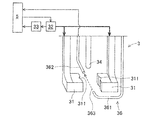
- the end effector 3 is provided in the hand section 23. As shown in FIG. 6, the end effector 3 has a holding portion 31, a magnet 34, and a light shielding detection sensor 36 (omitted in FIG. 1).
- the holding unit 31 holds and releases the works (93, 94) to perform the placement work.
- the holding unit 31 is a chuck that opens and closes to hold the work (93, 94).
- the chuck is composed of a pair of L-shaped members that open and close. The lower portions of the pair of L-shaped members closely face each other. A groove 311 extending vertically is formed on the facing surfaces of the L-shaped members. The workpieces (93, 94) are stably clamped at the holding position formed between both grooves 311.
- An air cylinder is provided as a drive source 32 that drives the holding unit 31. The drive source 32 is controlled by the robot controller 5. 6 and 7, the transmission of the driving force is shown by a thick arrow, and the transmission of signals and information is shown by a thin arrow.
- a work detection sensor 33 that indirectly detects whether the holding unit 31 holds the work (93, 94) by detecting the state of the drive source 32 is provided.
- the work detection sensor 33 outputs a detection signal to the robot controller 5.
- a cylinder pressure sensor that detects the pressure of the drive source 32 (air cylinder) can be exemplified.
- the magnet 34 is provided so as to move up and down through the holding position of the holding unit 31.
- the magnet 34 attracts and ascends the end of the first work 93 housed in the first supply box and the end of the shaft 942 of the second work 94 housed in the second supply box. Stand up (93, 94). After that, the upright works (93, 94) are held by the holding unit 31.
- the light-shielding detection sensor 36 includes a light emitting unit 361 and a light receiving unit 362 which are arranged with the holding position of the holding unit 31 interposed therebetween.
- the light emitting unit 361 emits detection light 363 that passes through the holding position.
- the light receiving unit 362 detects the detection light 363 that has passed through the holding position.
- the holding part 31 holds the work (93, 94)
- the detection light 363 is blocked by the work (93, 94). Therefore, the light receiving unit 362 does not detect the detection light 363, and can detect that the work (93, 94) is sandwiched.
- the light receiving unit 362 outputs the detection signal to the robot control unit 5.
- the end effector 3 is not limited to the above configuration.
- at least one of the magnet 34 and the light shielding detection sensor 36 may be omitted.
- a motor may be used as the drive source 32 that drives the holding unit 31, and a current sensor may be used as the work detection sensor 33.
- the holding unit 31 may be a nozzle that sucks the work (93, 94) using negative pressure.
- the work detection sensor 33 of the type that indirectly detects the work (93, 94) by detecting a change in negative pressure is used.
- the camera 4 is provided in the hand section 23.
- the camera 4 has a small size so as not to place a heavy load on the moving device 2, and is significantly smaller than the work target (91, 92). That is, since the camera 4 is required to have an open imaging viewing angle A (see FIG. 8), it is difficult to adopt the telecentric type. For this reason, the camera 4 adopts a method of capturing an image formed by light that is not parallel to the optical axis entering the lens.
- the camera 4 images the work target (91, 92) from above and acquires image data.
- the camera 4 is used for the purpose of recognizing the identification codes (914, 924) of the loaded work objects (91, 92) in the normal arrangement work of the work robot 1. Further, the camera 4 is used for the purpose of accurately detecting the stop positions of the work objects (91, 92) and the positions of the holes (911, 921).
- the camera 4 is a large product that is not driven by the moving device 2 and may be fixedly attached or may include a moving mechanism different from the moving device 2.
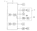
- the robot controller 5 controls the moving device 2, the drive source 32 of the end effector 3, and the camera 4. Further, the robot control unit 5 receives detection signals from the light receiving units 362 of the work detection sensor 33 and the light shielding detection sensor 36. Further, the robot control unit 5 controls the transport driving unit 98 to cause the transport conveyor 97 to carry in and out the work object (91, 92).
- the robot controller 5 is configured using a computer device.
- the robot control unit 5 includes an image processing unit 51, an image determination unit 52, a search processing unit 55, and a sensor determination unit 56 which are realized by software.
- the image processing unit 51 receives image data from the camera 4.
- the camera 4, the image processing unit 51, and the image determination unit 52 constitute a first determination unit.
- the search processing unit 55 also receives a detection signal from at least one of the work detection sensor 33 and the light shielding detection sensor 36. At least one of the sensors (33, 36), the search processing unit 55, and the sensor determination unit 56 constitutes a second determination unit.
- the work objects (91, 92) without any work (93, 94) placed therein are carried in.
- the work objects (91, 92) in which the works (93, 94) have already been placed are carried in due to a control error of the upstream transfer conveyor or a human error.
- the work robot 1 operates to place another work (93, 94) on top of the placed work (93, 94).
- the work robot 1 and the works (93, 94) may be in trouble.
- the first determination unit determines the presence or absence of the first work 93 on the first work target 91.
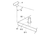
- the diameter of the circular cross section of the first work 93 is substantially equal to or slightly smaller than the inner diameter of the hole 911 of the first work target 91. Therefore, it is difficult to distinguish the first work 93 and the hole 911 even if the first work target 91 is imaged from directly above by the camera 4. Therefore, as shown in FIG. 8, the camera 4 captures the image data by obliquely capturing the first work target from above.
- the “occupied region” is a closed region obtained by performing image processing on image data, and means, for example, a closed region satisfying a predetermined luminance range or color range, or a closed region obtained by edge detection.
- the occupied area corresponds to the remaining portion of the first work 93 means that the size of the occupied area is close to the size of the image of the remaining portion of the first work 93 on the image data. ..
- the occupied area occupies an area of a predetermined range on the image data, or occupies the number of pixels of a predetermined number range on the image data. In other words, the occupied area is the amount in which only the range of the size of the area is defined regardless of the shape of the closed area.
- the range of the occupied area can be set experimentally in advance.
- the first work 93 is intentionally arranged in the hole 911 closest to the camera 4 and the hole 911 farthest from the camera 4 on the first work object 91, and image data is acquired by imaging the camera 4. Then, the shape and size of the protruding remaining portion of the first work 93 differ on the image data depending on the direction and distance viewed from the camera 4.
- the area of the projected remaining portion of the first work 93 inserted into the closest hole 911 on the image data is the maximum value of the occupied area. Further, the area of the projected remaining portion of the first work 93 inserted into the farthest hole 911 on the image data is the minimum value of the occupied area. Practically, a margin is added to the obtained maximum value and minimum value to set the range of the occupied area.
- the image determination unit 52 determines the presence or absence of the first work 93 on the first work target 91 based on the search result of the image processing unit 51. That is, when the image processing unit 51 recognizes the closed area corresponding to the occupied area, the image determination unit 52 determines that the first work 93 is present. When the image processing unit 51 does not recognize the closed area corresponding to the occupied area, the image determination unit 52 determines that the first work 93 does not exist.
- the camera 4 may acquire the plurality of image data by changing the diagonally upper position and the tilt angle.
- the focal length of the camera 4 may be switched to be short to approach the first work target 91, and only a part of the first work target 91 may be imaged. In these cases, the setting of the occupied area is changed.
- the camera 4 may perform image pickup from directly above. Even in this case, since the two-dimensional shapes of the plurality of first works 93 on the image data are different depending on the position, the determination using the occupied area is performed.
- the first determination unit makes a determination based on the size of the occupied area regardless of the two-dimensional shape of the first work 93 on the image data. According to this, even if the two-dimensional shapes of the plurality of first workpieces 93 located in various directions and distances within the imaging viewing angle A of the camera 4 differ on the image data, the risk of misjudgment is reduced. It Moreover, since the camera 4 is provided as a standard in a general work robot, the first determination unit does not cause an increase in device cost.
- the second determination unit determines the presence or absence of the second work 94 on the second work target 92.
- the second determination unit performs determination based on the height position of the grip 952 of the lid 95 that changes according to the presence or absence of the second work 94, instead of directly determining the presence or absence of the second work 94.
- the search processing unit 55 searches for the height position of the grip 952 using at least one of the sensors (33, 36).
- the search processing unit 55 moves the holding unit 31 to the predetermined height position of the grip 952 assuming that the second work 94 is present.
- the search processing unit 55 causes the holding unit 31 not holding the second work 94 to perform the holding operation of the grip 952.
- the search processing unit 55 acquires the detection result of the work detection sensor 33. Accordingly, the search processing unit 55 can determine whether the grip 952 is at the expected height position.
- the search processing unit 55 changes the planned height position of the grip 952 according to the length of the shaft portions 942. To do.
- the search processing unit 55 may move the light shielding detection sensor 36 to the predetermined height position of the grip 952 without using the holding unit 31. At this time, the search processing unit 55 can determine whether the grip 952 is at the expected height position based on whether the detection light 363 is blocked. Furthermore, the search processing unit 55 may use the detection result of the work detection sensor 33 and the detection result of the light shielding detection sensor 36 together to improve the certainty of the search.
- the sensor determination unit 56 determines the presence or absence of the second work 94 on the second work target 92 based on the search result of the search processing unit 55. That is, when the search processing unit 55 determines that the grip 952 is at the predetermined height position, the sensor determination unit 56 determines that the second work 94 is present, as shown in FIG. 9. Further, when the search processing unit 55 determines that the grip 952 is not at the predetermined height position, the sensor determination unit 56 determines that the second work 94 does not exist, as shown in FIG. 10.
- the second determination unit uses the sensors (33, 36) instead of the image processing of the image data, it is possible to reliably determine the presence or absence of the second work 94. Moreover, since at least one of the sensors (33, 36) is provided as a standard in a general work robot, the second determination unit does not increase the device cost.
- step S1 in the figure the robot control unit 5 controls the transport drive unit 98 and the transport conveyor 97 to load the work objects (91, 92) to the work execution position.
- step S2 the robot controller 5 controls the moving device 2 to move the camera 4 almost directly above the identification code (914, 924).
- the robot controller 5 controls the camera 4 to capture an image of the identification code (914, 924).
- the robot controller 5 recognizes the identification code (914, 924) from the acquired image data and identifies the type of the work target (91, 92).
- step S3 the robot control unit 5 branches the operation flow according to the type of the work object (91, 92).
- step S4 when the first work object 91 is loaded, the first determination unit performs the determination operation.
- step S5 when the second work object 92 is carried in, the second determination unit performs the determination operation.
- step S5 when the second work object 92 is carried in, the robot control unit 5 merges the execution of the operation flow with step S6.
- step S6 the robot control unit 5 determines whether or not the work (93, 94) is present on the work target (91, 92) based on the determination result of the first determination unit or the second determination unit. ..
- step S7 when there is no work (93, 94), the work robot 1 takes out the work (93, 94) from the first supply box or the second supply box and places it on the work target (91, 92). Perform the placement work to be placed in.
- the work robot 1 temporarily removes the lid 95 from the second work object 92 using the holding unit 31, and attaches the lid 95 again after the placement work is completed.
- the robot control unit 5 controls the transport drive unit 98 and the transport conveyor 97 to carry out the work objects (91, 92) for which the placement work has been completed.
- step S6 when there is at least one work (93, 94) on the work target (91, 92) in step S6, the work robot 1 does not perform the placement work, and the operation flow proceeds directly to step S8. That is, the work objects (91, 92) on which the works (93, 94) have been arranged are carried out as they are without the arrangement work by the work robot 1. After that, the execution of the operation flow is returned to step S1, and the placement work for the next work target (91, 92) is repeated.
- the image processing unit 51 searches the image data for an occupied area corresponding to the first work 93 for the first work target 91. Therefore, even if the two-dimensional shapes of the plurality of first works 93 on the image data are different, the image determination unit 52 can highly reliably determine the presence or absence of the first work 93 on the first work target 91. Further, the search processing unit 55 searches the second work object 92 using the at least one sensor (33, 36) of the end effector 3 for the second work object 92. Therefore, the sensor determination unit 56 can highly reliably determine the presence or absence of the second work 94 on the second work target 92.
- the work robot 1 does not perform an erroneous placement work of placing another work (93, 94) on the already-placed work (93, 94). Therefore, the risk of malfunction of the work robot 1 and the works (93, 94) is reduced. Further, since the camera 4 and the sensors (33, 36) of the conventional work robot are used to detect the work (93, 94) on the work target (91, 92), a dedicated sensor or the like is newly installed. There is no need, and the device cost does not rise.
- the determination method for the second work target 92 is different from that in the first embodiment. More specifically, in the case where there are a plurality of types of second works 94 having different lengths of the shaft portion 942, and an erroneous second work 94 different from the identification code 924 is arranged on the second work object 92, The expected height position of the grip 952 is incorrect. Further, there are cases where the lid 95 is not attached. In these cases, the second determination unit may make an erroneous determination. Therefore, not only the second determination unit but also the first determination unit makes a determination on the second work target 92.
- the lid 95 As the lid 95, the transparent or translucent lid 95 shown in FIG. 5 is used. Then, the camera 4 images the second work 94 through the transparent or translucent lid 95. After that, the first determination unit makes the same determination as in the first embodiment. At this time, the two-dimensional shape of the second work 94 may be deformed on the image data due to the refraction of light by the lid 95. Nevertheless, the first determination unit makes the determination using the occupied area that defines the range of the size of the area regardless of the shape of the closed area, and thus the risk of misjudgment is reduced.
- an opaque lid 96 having a cutout portion 961 is used.
- the size and position of the cutout portion 961 correspond to above a limited number of second workpieces 94.
- the camera 4 images the second work 94 through the cutout portion 961.
- the first determination unit makes the same determination as in the first embodiment.
- this determination method is not applied when the second work 94 is arranged in a part of the hole 921.
- the reliability of the determination is significantly improved because the first determination unit and the second determination unit are used in combination with either the transparent or translucent lid 95 or the opaque lid 96.
- the first work target object 91 The presence or absence of the first work 93 may be determined. Further, in step S6 of the operation flow of the first embodiment, when the workpieces (93, 94) are arranged only in a part of the holes (911, 921), the work robot 1 makes the holes (911, 921). Arrangement work for arranging the works (93, 94) may be performed on the remaining part of.
- the work robots 1 of the first and second embodiments can be applied to the work of attaching the work (93, 94) when the work target (91, 92) is a product. Further, in a configuration in which only the first work target 91 is loaded and unloaded, the work robot 1 does not have to include the search processing unit 55 and the sensor determination unit 56. Similarly, in a configuration in which only the second work target 92 is loaded and unloaded, the work robot 1 does not have to include the image processing unit 51 and the image determination unit 52. Besides, the first and second embodiments can be variously applied and modified.
Landscapes
- Engineering & Computer Science (AREA)
- Human Computer Interaction (AREA)
- Robotics (AREA)
- Mechanical Engineering (AREA)
- Manipulator (AREA)
Abstract
作業ロボットは、作業対象物に配置するワークを保持可能なエンドエフェクタと、前記エンドエフェクタを移動させる移動装置と、前記作業対象物を上方から撮像して画像データを取得するカメラと、前記画像データ上で前記ワークに対応する占有領域を探索する画像処理部と、前記画像処理部の探索結果に基づいて、前記作業対象物上の前記ワークの有無を判定する画像判定部と、を備える。
Description
本明細書は、作業ロボットに関する。
工場や事業所などの自動化、省力化を推進するために、作業ロボットが広く用いられている。多くの作業ロボットは、ワークを保持するエンドエフェクタを備える。また、多くの作業ロボットは、カメラを用いて作業対象物を撮像し、作業対象物の有無や、置かれた位置および姿勢などを確認して、作業を進める。この種の作業ロボットに関する技術例が、特許文献1、2に開示されている。
特許文献1のトレイ式仕分け装置は、搬送路に沿って走行する複数のトレイと、トレイ上の搬送物の有無を識別する検出手段とを備える。トレイの載置面には凹凸が形成され、検出手段は、トレイを撮像した撮像データと、トレイの凹部から得られる位置と色調に関する基準画像データとを比較することにより、搬送物の有無を識別する。これによれば、搬送物とトレイのこすれにより生じるキズの影響を受けることなく、搬送物の検出が可能になる、とされている。
また、特許文献2のワーク搬送制御装置は、ワークを配置する載置場所を撮影するカメラと、カメラによって取得された撮影画像に基づいてワークの有無および位置を検出する検出装置と、ワークの位置情報に基づいてワーク保持用ロボットを制御する制御装置と、を備える。これによれば、従来よりも多くのワークを加工機へと連続的に搬送することができる、とされている。
ところで、特許文献1、2では、カメラを用いて作業対象物を撮像し、取得した画像データ上で所定のワーク形状を探索する判定方法が用いられる。しかしながら、ワーク形状を探索する従来の判定方法では、十分な信頼性が得られない場合がある。例えば、広い作業対象物の上面に多数のワークが配置される場合、ワークの各々は、カメラから見て様々な方向に位置するとともに、カメラとの離間距離が相違する。このため、複数のワークの二次元形状が画像データ上で相違して、誤判定となるおそれが生じる。
仮に、作業対象物上に配置済みのワークが誤って「無い」と判定されると、作業ロボットやワークに不具合が発生する要因となり得る。さらに、ワークを養生する等の目的で蓋が使用される場合には、ワークの有無の判定が一層難しくなる。
また、作業対象物を搬送する搬送路や作業実施位置に、ワークの有無を検出するセンサを設ける構成が、従来から用いられてきた。しかしながら、センサは、作業対象物に設けられた取手などの付属物をワークと誤検出するおそれがある。加えて、センサの取り付けスペースの制約や、コスト増加が難点となる。
本明細書では、高い信頼性で作業対象物上のワークの有無を判定できる作業ロボットを提供することを解決すべき課題とする。
本明細書は、作業対象物に配置するワークを保持可能なエンドエフェクタと、前記エンドエフェクタを移動させる移動装置と、前記作業対象物を上方から撮像して画像データを取得するカメラと、前記画像データ上で前記ワークに対応する占有領域を探索する画像処理部と、前記画像処理部の探索結果に基づいて、前記作業対象物上の前記ワークの有無を判定する画像判定部と、を備える作業ロボットを開示する。
また、本明細書は、作業対象物に配置するワークを保持する保持部、および前記保持部に保持された前記ワークを検出するセンサを有するエンドエフェクタと、前記エンドエフェクタを移動させる移動装置と、前記センサを用いて、前記作業対象物上の前記ワークを探索する探索処理部と、前記探索処理部の探索結果に基づいて、前記作業対象物上の前記ワークの有無を判定するセンサ判定部と、を備える作業ロボットを開示する。
本明細書で開示する作業ロボットによれば、画像データ上でワークに対応する占有領域を探索するので、画像データ上の複数のワークの二次元形状が相違しても、高い信頼性で作業対象物上のワークの有無を判定できる。あるいは、画像データの画像処理に代え、エンドエフェクタが有するセンサを用いてワークを探索するので、高い信頼性で作業対象物上のワークの有無を判定できる。
1.作業対象物(91、92)および作業ロボット1の構成
第1実施形態における作業対象物(91、92)および作業ロボット1の構成について図1~図7を参考にして説明する。作業ロボット1は、第1作業対象物91に第1ワーク93を配置する配置作業、および第2作業対象物92に第2ワーク94を配置する配置作業を実施する。詳細には、作業ロボット1は、作業対象物(91、92)の複数の孔(911、921)にそれぞれワーク(93、94)を挿入して配置する。ワーク(93、94)が配置された作業対象物(91、92)は、下流工程の別の作業ロボットへ搬送されて、組立作業に使用される。
第1実施形態における作業対象物(91、92)および作業ロボット1の構成について図1~図7を参考にして説明する。作業ロボット1は、第1作業対象物91に第1ワーク93を配置する配置作業、および第2作業対象物92に第2ワーク94を配置する配置作業を実施する。詳細には、作業ロボット1は、作業対象物(91、92)の複数の孔(911、921)にそれぞれワーク(93、94)を挿入して配置する。ワーク(93、94)が配置された作業対象物(91、92)は、下流工程の別の作業ロボットへ搬送されて、組立作業に使用される。
図2に示されるように、第1作業対象物91は、概ね長方形のパレット部材である。第1作業対象物91は、その長辺と平行する方向に搬入出される。第1作業対象物91の上面に、複数(図2の例では70個)の断面円形の孔911が設けられる。孔911は、第1ワーク93が配置される予定位置である。孔911の入り口に座刳り部912が形成されて、第1ワーク93の挿入が容易となっている。図3に示されるように、第1ワーク93は、円形断面を有する鉄製の細長いピンであり、その一部が孔911に挿入される。
第1作業対象物91の二つの短辺に、それぞれ取手913が設けられる。第1作業対象物91のひとつのコーナー(図2の左上のコーナー)付近に、識別コード914が付設される。識別コード914は、第1作業対象物91および第1ワーク93の種類を特定するものである。識別コード914として、バーコードやマトリックス型二次元コード、数字列などが用いられる。
図4に示されるように、第2作業対象物92は、第1作業対象物91と概ね同じ大きさの長方形のパレット部材である。第2作業対象物92は、その長辺と平行する方向に搬入出される。第2作業対象物92の上面に、複数(図2の例では54個)の断面円形の孔921が設けられる。孔921は、第2ワーク94が配置される予定位置である。第2ワーク94は、頭部941、およびねじが形成された軸部942からなる鉄製のボルトである。図4において、頭部941は、黒色で示されている。第2ワーク94は、頭部941が孔921に挿入され、軸部942を上に向けて配置される。
第2作業対象物92の二つの短辺に、それぞれ取手923が設けられる。第2作業対象物92のひとつのコーナー(図4の左上のコーナー)の付近に、識別コード924が付設される。識別コード924は、第2作業対象物92および第2ワーク94の種類を特定するものである。第2作業対象物92の対角線上の二つのコーナー(図4の右上および左下のコーナー)の付近に、それぞれガイドピン925が立設される。
図5に示される蓋95は、第2ワーク94を養生して、軸部942のねじ溝に塵埃が付着することを防止する目的で使用される。蓋95は、透明または半透明とされ、第2作業対象物92よりも若干小さめの長方形に形成される。蓋95の対角線上の二つのコーナー(図4の右上および左下のコーナー)の付近に、それぞれガイド孔951が設けられる。第2作業対象物92の2本のガイドピン925は、それぞれ蓋95のガイド孔951に嵌入する。これにより、蓋95は、上下方向に案内され、かつ水平方向の位置が定められる。
蓋95の上面の中央に、グリップ952が設けられる。グリップ952は、蓋95の長辺方向に長く、かつ中央部が両側より高く形成されている。グリップ952は、人の指や作業ロボット1の保持部31(後述)などによって挟持される。これにより、蓋95の取り付けおよび取り外しが行われる。
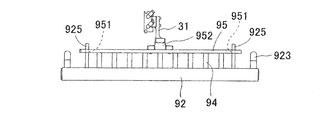
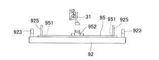
蓋95は、配置作業時に取り外され、配置作業時以外には第2ワーク94の有無に関係なく取り付けられる。蓋95は、第2作業対象物92を覆いつつ、配置された第2ワーク94によって支持される(図9参照)。また、第2ワーク94が配置されていないとき、蓋95は、第2作業対象物92の上面に接する(図10参照)。したがって、蓋95の高さ位置は、第2ワーク94の有無に応じて変化する。さらに、第2ワーク94が複数種類あって軸部942の長さが相違する場合、蓋95の高さ位置は、軸部942の長さに応じて変化する。
図1に示されるように、第1作業対象物91および第2作業対象物92を自動で作業実施位置に搬入出する用途に、搬送コンベア97が設けられる。図7に示されるように、搬送コンベア97は、搬送駆動部98から駆動される。搬送駆動部98は、ロボット制御部5から制御される。搬送コンベア97は、作業対象物(91、92)が載置された状態で搬送路に沿って輪転するコンベアベルトを有する。搬送駆動部98として、コンベアベルトを駆動するモータを例示できる。なお、第1作業対象物91および第2作業対象物92は、人手によって作業実施位置に搬入出されてもよい。
図1および図7に示されるように、作業ロボット1は、基体部10、移動装置2、エンドエフェクタ3、カメラ4、およびロボット制御部5などで構成される。基体部10は、作業実施位置に臨んで固定取り付けされる。基体部10の近傍に、多数の第1ワーク93を横向きにまたはランダムな向きに収容した第1供給箱(図略)が配置される。同様に、基体部10の近傍に、多数の第2ワーク94を横向きにまたはランダムな向きに収容した第2供給箱(図略)が配置される。
移動装置2は、多関節タイプのアームを用いて構成される。移動装置2のアーム基端部21は、基体部10の上側に支持され、鉛直軸の周りに回転可能となっている。さらに、移動装置2(アーム)は、あらゆる方向に向かって延在可能であるとともに、長さ方向の途中で自在に折れ曲がることができるように構成されている。したがって、移動装置2のアーム先端部22は、作業実施位置の上方の任意の空間位置に移動することができる。アーム先端部22には、ハンド部23が揺動可能に設けられる。移動装置2は、エンドエフェクタ3およびカメラ4を揃って移動させる。
エンドエフェクタ3は、ハンド部23に設けられている。図6に示されるように、エンドエフェクタ3は、保持部31、磁石34、遮光検出センサ36を有する(図1では省略)。保持部31は、ワーク(93、94)を保持および解放して、配置作業を実施する。保持部31は、開閉してワーク(93、94)を挟持動作するチャックとされている。
チャックは、開閉動作する一対のL字状部材で構成される。一対のL字状部材の下部は、近接して対向する。そして、L字状部材の向かい合う対向面に、上下に延びる溝311が形成されている。ワーク(93、94)は、両方の溝311の間に形成される保持位置に安定して挟持される。保持部31を駆動する駆動源32として、エアシリンダが設けられる。駆動源32は、ロボット制御部5から制御される。なお、図6および図7において、駆動力の伝達は太線の矢印で示され、信号や情報の伝達は細線の矢印で示されている。
さらに、駆動源32の状態を検出して、保持部31がワーク(93、94)を保持しているか否かを間接的に検出するワーク検出センサ33が設けられる。ワーク検出センサ33は、検出信号をロボット制御部5に出力する。ワーク検出センサ33として、駆動源32(エアシリンダ)の圧力を検出するシリンダ圧力センサを例示できる。
磁石34は、保持部31の保持位置を通って昇降するように設けられる。磁石34は、第1供給箱に収容されている第1ワーク93の端部や、第2供給箱に収容されている第2ワーク94の軸部942の端部を吸引して上昇し、ワーク(93、94)を起立させる。この後、起立したワーク(93、94)は、保持部31により挟持される。
遮光検出センサ36は、保持部31の保持位置を挟んで配置された発光部361および受光部362からなる。発光部361は、保持位置を通る検出光363を発射する。受光部362は、保持位置を通過した検出光363を検出する。保持部31がワーク(93、94)を挟持していると、当該のワーク(93、94)により検出光363が遮断される。したがって、受光部362は、検出光363を検出しなくなり、ワーク(93、94)が挟持されていることを検出できる。受光部362は、検出信号をロボット制御部5に出力する。
なお、エンドエフェクタ3は、上述した構成に限定されない。例えば、磁石34および遮光検出センサ36の少なくとも一方が省略されてもよい。また、保持部31を駆動する駆動源32にモータが用いられ、ワーク検出センサ33に電流センサが用いられてもよい。さらに、保持部31は、負圧を利用してワーク(93、94)を吸着するノズルであってもよい。この態様では、負圧の変化を検出してワーク(93、94)を間接的に検出する方式のワーク検出センサ33が使用される。
カメラ4は、ハンド部23に設けられている。カメラ4は、移動装置2の大きな負荷とならないように小型品が採用され、作業対象物(91、92)よりも格段に小さい。つまり、カメラ4は、開いた撮像視野角A(図8参照)が要求されるため、テレセントリック型の採用が難しい。このため、カメラ4は、光軸に対して非平行な光がレンズに入射して形成される画像を撮像する方式とされる。カメラ4は、作業対象物(91、92)を上方から撮像して画像データを取得する。
作業ロボット1の通常時の配置作業において、カメラ4は、搬入された作業対象物(91、92)の識別コード(914、924)を認識する用途に使用される。さらに、カメラ4は、作業対象物(91、92)の停止位置や、孔(911、921)の位置を正確に検出する用途に使用される。なお、カメラ4は、移動装置2に駆動されない大型品であって、固定取り付けされ、または移動装置2と別の移動機構を備えてもよい。
2.作業ロボット1の制御の構成、第一判定部および第二判定部の判定方法
次に、作業ロボット1の制御の構成と、第一判定部および第二判定部の判定方法について説明する。図7に示されるように、ロボット制御部5は、移動装置2、エンドエフェクタ3の駆動源32、およびカメラ4を制御する。また、ロボット制御部5は、ワーク検出センサ33および遮光検出センサ36の受光部362から検出信号を受け取る。さらに、ロボット制御部5は、搬送駆動部98を制御して、搬送コンベア97に作業対象物(91、92)の搬入出を行わせる。ロボット制御部5は、コンピュータ装置を用いて構成される。
次に、作業ロボット1の制御の構成と、第一判定部および第二判定部の判定方法について説明する。図7に示されるように、ロボット制御部5は、移動装置2、エンドエフェクタ3の駆動源32、およびカメラ4を制御する。また、ロボット制御部5は、ワーク検出センサ33および遮光検出センサ36の受光部362から検出信号を受け取る。さらに、ロボット制御部5は、搬送駆動部98を制御して、搬送コンベア97に作業対象物(91、92)の搬入出を行わせる。ロボット制御部5は、コンピュータ装置を用いて構成される。
ロボット制御部5は、ソフトウェアによって実現された画像処理部51、画像判定部52、探索処理部55、およびセンサ判定部56を含む。画像処理部51は、カメラ4から画像データを受け取る。カメラ4、画像処理部51、および画像判定部52によって第一判定部が構成される。また、探索処理部55は、ワーク検出センサ33および遮光検出センサ36の少なくとも一方から検出信号を受け取る。少なくとも一方のセンサ(33、36)、探索処理部55、およびセンサ判定部56によって第二判定部が構成される。
ここで、作業ロボット1の通常時の配置作業では、ワーク(93、94)が1個も配置されていない作業対象物(91、92)が搬入される。しかしながら、上流側の搬送コンベアの制御誤りや人為的な作業ミスなどの原因で、既にワーク(93、94)が配置済みの作業対象物(91、92)が搬入されるケースが皆無ではない。これを看過して、作業ロボット1が配置作業を開始すると、配置済みのワーク(93、94)に重ねて別のワーク(93、94)を配置するように動作する。これにより、作業ロボット1やワーク(93、94)に不具合のおそれが生じる。
この対策として、第一判定部および第二判定部が設けられる。第一判定部は、第1作業対象物91上の第1ワーク93の有無を判定する。ここで、第1ワーク93の円形断面の直径は、第1作業対象物91の孔911の内径に略等しいか、またはわずかに小さい。したがって、カメラ4により真上から第1作業対象物91を撮像しても、第1ワーク93と孔911とを区別することが難しい。このため、図8に示されるように、カメラ4は、第1作業対象物を斜め上方から撮像して画像データを取得する。
次に、画像処理部51は、画像データ上で第1ワーク93の孔911から突出した残部に対応する占有領域を探索する。「占有領域」とは、画像データに画像処理を施して求められる閉領域であり、例えば、所定の輝度範囲や色範囲を満足する閉領域や、エッジ検出によって求められる閉領域を意味する。また、「占有領域が第1ワーク93の残部に対応する」とは、画像データ上において、占有領域の大きさが第1ワーク93の残部の画像の大きさに近似していることを意味する。占有領域は、画像データ上で所定範囲の面積を占め、または、画像データ上で所定個数範囲の画素数を占める。つまり、占有領域は、閉領域の形状を問わず、面積の大きさの範囲のみが規定された量である。
占有領域の範囲は、予め実験的に設定することが可能である。例えば、第1作業対象物91上のカメラ4に最も近い孔911、およびカメラ4から最も遠い孔911に意図的に第1ワーク93を配置して、カメラ4の撮像により画像データを取得する。すると、カメラ4からみた方向および距離に応じて、第1ワーク93の突出した残部の形状および大きさが画像データ上で相違する。最も近い孔911に挿入された第1ワーク93の突出した残部の画像データ上に占める面積が、占有領域の最大値となる。また、最も遠い孔911に挿入された第1ワーク93の突出した残部の画像データ上に占める面積が、占有領域の最小値となる。実用的には、求めた最大値および最小値にマージンが加えられて、占有領域の範囲が設定される。
画像判定部52は、画像処理部51の探索結果に基づいて、第1作業対象物91上の第1ワーク93の有無を判定する。つまり、画像処理部51が占有領域に該当する閉領域を認識した場合に、画像判定部52は、第1ワーク93が有ると判定する。また、画像処理部51が占有領域に該当する閉領域を認識しなかった場合に、画像判定部52は、第1ワーク93が無いと判定する。
なお、画像データ上で複数の第1ワーク93の画像が重なって検索が難しい場合に、カメラ4は、斜め上方の位置や傾斜角度を変更して、複数の画像データを取得してもよい。また、カメラ4の焦点距離を短く切り替えて第1作業対象物91に接近し、第1作業対象物91の一部分のみを撮像してもよい。これらの場合、占有領域の設定が変更される。また、第1ワーク93に複数の種類が有って、孔911から突出した残部の長さが相違する場合、同様に占有領域の設定が変更される。さらに、第1ワーク93と孔911の区別が容易であれば、カメラ4による真上からの撮像を行ってもよい。この場合でも、画像データ上の複数の第1ワーク93の二次元形状が位置に依存して相違するため、占有領域を用いた判定が行われる。
上記したように、第一判定部では、画像データ上で第1ワーク93の二次元形状を問わず、占有領域の大きさに基づいた判定を行う。これによれば、カメラ4の撮像視野角A内の様々な方向および距離に位置する複数の第1ワーク93の二次元形状が画像データ上で相違しても、誤判定となるおそれが低減される。また、カメラ4は、一般的な作業ロボットに標準的に設けられているので、第一判定部は、装置コストの上昇を招かない。
次に、第二判定部は、第2作業対象物92上の第2ワーク94の有無を判定する。ここで、第2作業対象物92には蓋95が使用されるため、第一判定部では対応が難しい。第二判定部は、第2ワーク94の有無を直接的に判定することに代え、第2ワーク94の有無に応じて変化する蓋95のグリップ952の高さ位置による判定を行う。まず、探索処理部55は、少なくとも一方のセンサ(33、36)を用いて、グリップ952の高さ位置を探索する。
詳述すると、探索処理部55は、図9に示されるように、第2ワーク94が有ると仮定したときのグリップ952の予定の高さ位置へ保持部31を移動させる。次に、探索処理部55は、第2ワーク94を挟持していない保持部31にグリップ952の挟持動作を行わせる。そして、探索処理部55は、ワーク検出センサ33の検出結果を取得する。これにより、探索処理部55は、グリップ952が予定の高さ位置に有るか否かを判定することができる。なお、第2ワーク94に複数の種類が有って軸部942の長さが相違する場合、探索処理部55は、軸部942の長さに合わせてグリップ952の予定の高さ位置を変更する。
また、探索処理部55は、保持部31を使用せずに、グリップ952の予定の高さ位置へ遮光検出センサ36を移動させてもよい。このとき、検出光363が遮光されたか否かにより、探索処理部55は、グリップ952が予定の高さ位置に有るか否かを判定できる。さらに、探索処理部55は、ワーク検出センサ33の検出結果および遮光検出センサ36の検出結果を併用して、探索の確実性を向上してもよい。
センサ判定部56は、探索処理部55の探索結果に基づいて、第2作業対象物92上の第2ワーク94の有無を判定する。つまり、探索処理部55によってグリップ952が予定の高さ位置に有ると判定されたとき、センサ判定部56は、図9に示されるように第2ワーク94が有ると判定する。また、探索処理部55によってグリップ952が予定の高さ位置に無いと判定されたとき、センサ判定部56は、図10に示されるように第2ワーク94が無いと判定する。
上記したように、第二判定部は、画像データの画像処理に代えて、センサ(33、36)を用いるので、第2ワーク94の有無を確実に判定することができる。また、少なくとも一方のセンサ(33、36)は、一般的な作業ロボットに標準的に設けられているので、第二判定部は、装置コストの上昇を招かない。
3.作業ロボット1の総合的な動作
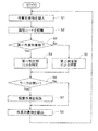
次に、作業ロボット1の総合的な動作について説明する。図11の動作フローは、主にロボット制御部5からの制御にしたがって進められる。図中のステップS1で、ロボット制御部5は、搬送駆動部98および搬送コンベア97を制御して、作業対象物(91、92)を作業実施位置に搬入させる。次のステップS2で、ロボット制御部5は、移動装置2を制御して、カメラ4を識別コード(914、924)の概ね真上に移動させる。続いて、ロボット制御部5は、カメラ4を制御して、識別コード(914、924)を撮像させる。続いて、ロボット制御部5は、取得された画像データから識別コード(914、924)を認識して、作業対象物(91、92)の種類を特定する。
次に、作業ロボット1の総合的な動作について説明する。図11の動作フローは、主にロボット制御部5からの制御にしたがって進められる。図中のステップS1で、ロボット制御部5は、搬送駆動部98および搬送コンベア97を制御して、作業対象物(91、92)を作業実施位置に搬入させる。次のステップS2で、ロボット制御部5は、移動装置2を制御して、カメラ4を識別コード(914、924)の概ね真上に移動させる。続いて、ロボット制御部5は、カメラ4を制御して、識別コード(914、924)を撮像させる。続いて、ロボット制御部5は、取得された画像データから識別コード(914、924)を認識して、作業対象物(91、92)の種類を特定する。
次のステップS3で、ロボット制御部5は、作業対象物(91、92)の種類に応じて動作フローを分岐させる。第1作業対象物91が搬入されているときのステップS4で、第一判定部が判定動作を行う。また、第2作業対象物92が搬入されているときのステップS5で、第二判定部が判定動作を行う。ステップS4またはステップS5の実行後に、ロボット制御部5は、動作フローの実行をステップS6に合流させる。
ステップS6で、ロボット制御部5は、第一判定部または第二判定部の判定結果に基づいて、作業対象物(91、92)上にワーク(93、94)が有るか否かを判定する。ワーク(93、94)が1個も無いときのステップS7で、作業ロボット1は、第1供給箱または第2供給箱からワーク(93、94)を取り出し、作業対象物(91、92)上に配置する配置作業を実施する。なお、作業ロボット1は、第2作業対象物92に対し、保持部31を用いて蓋95を一時的に取り外し、配置作業の終了後に再び蓋95を取り付ける。次のステップS8で、ロボット制御部5は、搬送駆動部98および搬送コンベア97を制御して、配置作業が終了した作業対象物(91、92)を搬出させる。
また、ステップS6で、作業対象物(91、92)上に1個でもワーク(93、94)が有るとき、作業ロボット1は配置作業を実施せず、動作フローは直接ステップS8に進められる。つまり、ワーク(93、94)が配置済みの作業対象物(91、92)は、作業ロボット1による配置作業が実施されずに、そのまま搬出される。この後、動作フローの実行はステップS1に戻され、次の作業対象物(91、92)への配置作業が繰り返される。
第1実施形態の作業ロボット1において、画像処理部51は、第1作業対象物91について、画像データ上で第1ワーク93に対応する占有領域を探索する。したがって、画像データ上の複数の第1ワーク93の二次元形状が相違しても、画像判定部52は、高い信頼性で第1作業対象物91上の第1ワーク93の有無を判定できる。また、探索処理部55は、第2作業対象物92について、エンドエフェクタ3が有する少なくとも一方のセンサ(33、36)を用いて第2ワーク94を探索する。したがって、センサ判定部56は、高い信頼性で第2作業対象物92上の第2ワーク94の有無を判定できる。
このため、作業ロボット1は、配置済みのワーク(93、94)に重ねて別のワーク(93、94)を配置するという誤った配置作業を実施することがない。したがって、作業ロボット1やワーク(93、94)の不具合のおそれが低減される。さらに、作業対象物(91、92)上のワーク(93、94)を検出するために、従来の作業ロボットが有するカメラ4やセンサ(33、36)を用いるので、専用のセンサ等を新設する必要が無く、装置コストが上昇しない。
4.第2実施形態の作業ロボット1
次に、第2実施形態の作業ロボット1について、第1実施形態と異なる点を主にして説明する。第2実施形態では、第2作業対象物92に対する判定方法が第1実施形態と異なる。詳述すると、軸部942の長さが相違する複数種類の第2ワーク94があり、識別コード924と異なる誤った第2ワーク94が第2作業対象物92上に配置されているケースでは、グリップ952の予定の高さ位置が誤ったものとなる。また、蓋95が取り付けられていないケースが皆無ではない。これらのケースにおいて、第二判定部は、誤判定するおそれがある。したがって、第2作業対象物92に対して、第二判定部だけでなく第一判定部も判定を行う。
次に、第2実施形態の作業ロボット1について、第1実施形態と異なる点を主にして説明する。第2実施形態では、第2作業対象物92に対する判定方法が第1実施形態と異なる。詳述すると、軸部942の長さが相違する複数種類の第2ワーク94があり、識別コード924と異なる誤った第2ワーク94が第2作業対象物92上に配置されているケースでは、グリップ952の予定の高さ位置が誤ったものとなる。また、蓋95が取り付けられていないケースが皆無ではない。これらのケースにおいて、第二判定部は、誤判定するおそれがある。したがって、第2作業対象物92に対して、第二判定部だけでなく第一判定部も判定を行う。
第2実施形態において、蓋95は、図5に示される透明または半透明の蓋95が使用される。そして、カメラ4は、透明または半透明の蓋95を透かして第2ワーク94を撮像する。その後、第一判定部は、第1実施形態と同様の判定を行う。このとき、蓋95における光の屈折に起因して、第2ワーク94の二次元形状が画像データ上で変形し得る。それでも、第一判定部は、閉領域の形状を問わず面積の大きさの範囲を規定した占有領域を用いて判定を行うので、誤判定となるおそれが低減される。
あるいは、図12に示されるように、切り欠き部961が形成された不透明の蓋96が使用される。切り欠き部961の大きさおよび位置は、限られた個数の第2ワーク94の上方に対応する。そして、カメラ4は、切り欠き部961を通して第2ワーク94を撮像する。その後、第一判定部は、第1実施形態と同様の判定を行う。ただし、この判定方法は、孔921の一部に第2ワーク94が配置される場合には適用されない。第2実施形態において、透明または半透明の蓋95、不透明の蓋96のどちらの場合でも、第一判定部および第二判定部が併用されるので、判定の信頼性が格段に向上する。
5.実施形態の応用および変形
なお、第1作業対象物91に対して第二判定部が動作し、保持部31が第1ワーク93を挟持するか否かに応じて、第1作業対象物91上の第1ワーク93の有無を判定してもよい。また、第1実施形態の動作フローのステップS6で、孔(911、921)の一部のみにワーク(93、94)が配置されているときに、作業ロボット1は、孔(911、921)の残部に、ワーク(93、94)を配置する配置作業を実施してもよい。
なお、第1作業対象物91に対して第二判定部が動作し、保持部31が第1ワーク93を挟持するか否かに応じて、第1作業対象物91上の第1ワーク93の有無を判定してもよい。また、第1実施形態の動作フローのステップS6で、孔(911、921)の一部のみにワーク(93、94)が配置されているときに、作業ロボット1は、孔(911、921)の残部に、ワーク(93、94)を配置する配置作業を実施してもよい。
さらに、第1および第2実施形態の作業ロボット1は、作業対象物(91、92)が製品であって、ワーク(93、94)を取り付ける作業に応用することができる。また、第1作業対象物91のみが搬入出される構成において、作業ロボット1は、探索処理部55およびセンサ判定部56を備えなくてもよい。同様に、第2作業対象物92のみが搬入出される構成において、作業ロボット1は、画像処理部51および画像判定部52を備えなくてもよい。その他にも、第1および第2実施形態は、様々な応用や変形が可能である。
1:作業ロボット 2:移動装置 3:エンドエフェクタ 31:保持部 32:駆動源 33:ワーク検出センサ 34:磁石 36:遮光検出センサ 4:カメラ 5:ロボット制御部 51:画像処理部 52:画像判定部 55:探索処理部 56:センサ判定部 91:第1作業対象物 911:孔 92:第2作業対象物 921:孔 93:第1ワーク 94:第2ワーク 95:蓋 952:グリップ 96:蓋 97:搬送コンベア 98:搬送駆動部
Claims (13)
- 作業対象物に配置するワークを保持可能なエンドエフェクタと、
前記エンドエフェクタを移動させる移動装置と、
前記作業対象物を上方から撮像して画像データを取得するカメラと、
前記画像データ上で前記ワークに対応する占有領域を探索する画像処理部と、
前記画像処理部の探索結果に基づいて、前記作業対象物上の前記ワークの有無を判定する画像判定部と、
を備える作業ロボット。 - 前記ワークに対応する前記占有領域は、前記画像データ上で所定範囲の面積を占める領域、または、前記画像データ上で所定個数範囲の画素数を占める領域である、請求項1に記載の作業ロボット。
- 前記カメラは、光軸に対して非平行な光がレンズに入射して形成される画像を撮像する、請求項1または2に記載の作業ロボット。
- 前記カメラは、前記作業対象物を斜め上方から撮像する、請求項1~3のいずれか一項に記載の作業ロボット。
- 前記作業対象物は、前記ワークの一部が挿入される孔を有し、
前記画像処理部は、前記孔に挿入された前記ワークの前記孔から突出した残部に対応する前記占有領域を探索する、
請求項4に記載の作業ロボット。 - 前記作業対象物の搬入出時に前記作業対象物および前記ワークを覆うように取り付けられ、かつ前記ワークが配置される作業時に取り外される蓋が使用され、
前記カメラは、透明または半透明の前記蓋を透かして撮像し、または、前記蓋に形成された切り欠き部を通して撮像する、
請求項1~5のいずれか一項に記載の作業ロボット。 - 前記エンドエフェクタは、前記ワークを保持する保持部、および前記保持部に保持された前記ワークを検出するセンサを有し、
前記作業ロボットは、
前記センサを用いて、前記作業対象物上の前記ワークを探索する探索処理部と、
前記探索処理部の探索結果に基づいて、前記作業対象物上の前記ワークの有無を判定するセンサ判定部と、を備え、
同一の前記作業対象物に対し、前記カメラ、前記画像処理部、および前記画像判定部からなる第一判定部、ならびに、前記センサ、前記探索処理部、および前記センサ判定部からなる第二判定部が動作して前記ワークの有無を判定し、または、
前記作業対象物の種類および配置予定の前記ワークの種類の少なくとも一方に応じて、前記第一判定部および前記第二判定部の少なくとも一方が動作する、
請求項1~6のいずれか一項に記載の作業ロボット。 - 作業対象物に配置するワークを保持する保持部、および前記保持部に保持された前記ワークを検出するセンサを有するエンドエフェクタと、
前記エンドエフェクタを移動させる移動装置と、
前記センサを用いて、前記作業対象物上の前記ワークを探索する探索処理部と、
前記探索処理部の探索結果に基づいて、前記作業対象物上の前記ワークの有無を判定するセンサ判定部と、
を備える作業ロボット。 - 前記保持部は、前記ワークを挟持するチャックであり、
前記センサは、前記チャックの開閉状態を直接的にまたは間接的に検出することにより前記ワークを検出し、
前記探索処理部は、前記ワークが配置される前記作業対象物上の予定位置で、前記ワークを挟持していない前記チャックに挟持動作を行わせて、前記センサの検出結果を取得する、
請求項8に記載の作業ロボット。 - 前記保持部は、負圧を利用して前記ワークを吸着するノズルであり、
前記センサは、前記負圧の変化を検出することにより前記ワークを検出し、
前記探索処理部は、前記ワークが配置される前記作業対象物上の予定位置で、前記ワークを吸着していない前記ノズルに吸着動作を行わせて、前記センサの検出結果を取得する、
請求項8に記載の作業ロボット。 - 前記センサは、前記ワークによる検出光の遮断を検出することにより前記ワークを検出し、
前記探索処理部は、前記ワークが配置される前記作業対象物上の予定位置に前記センサの検出部を移動させて、前記センサの検出結果を取得する、
請求項8に記載の作業ロボット。 - 前記作業対象物の搬入出時に前記作業対象物を覆いつつ、配置された前記ワークによって支持されるように取り付けられるとともに、前記ワークの有無に応じてその高さ位置が変化し、かつ前記ワークが配置される作業時に取り外される蓋が使用され、
前記探索処理部は、前記ワークに代えて前記蓋の特定部位の前記高さ位置を探索する、
請求項8~11のいずれか一項に記載の作業ロボット。 - 前記作業対象物は、前記ワークが配置される予定位置が複数設けられており、
前記作業ロボットは、前記作業対象物上に前記ワークが1個も無いと判定された後に、前記作業対象物上に前記ワークを配置する作業を開始する、
請求項1~12のいずれか一項に記載の作業ロボット。
Priority Applications (2)
| Application Number | Priority Date | Filing Date | Title |
|---|---|---|---|
| JP2020562266A JP7177856B2 (ja) | 2018-12-28 | 2018-12-28 | 作業ロボット |
| PCT/JP2018/048452 WO2020136867A1 (ja) | 2018-12-28 | 2018-12-28 | 作業ロボット |
Applications Claiming Priority (1)
| Application Number | Priority Date | Filing Date | Title |
|---|---|---|---|
| PCT/JP2018/048452 WO2020136867A1 (ja) | 2018-12-28 | 2018-12-28 | 作業ロボット |
Publications (1)
| Publication Number | Publication Date |
|---|---|
| WO2020136867A1 true WO2020136867A1 (ja) | 2020-07-02 |
Family
ID=71127858
Family Applications (1)
| Application Number | Title | Priority Date | Filing Date |
|---|---|---|---|
| PCT/JP2018/048452 Ceased WO2020136867A1 (ja) | 2018-12-28 | 2018-12-28 | 作業ロボット |
Country Status (2)
| Country | Link |
|---|---|
| JP (1) | JP7177856B2 (ja) |
| WO (1) | WO2020136867A1 (ja) |
Citations (7)
| Publication number | Priority date | Publication date | Assignee | Title |
|---|---|---|---|---|
| JPS6239152A (ja) * | 1985-08-13 | 1987-02-20 | Toshiba Corp | ロボツト |
| JPH08243961A (ja) * | 1995-03-06 | 1996-09-24 | Toyoda Mach Works Ltd | ワーク取り出し装置 |
| JP2002299418A (ja) * | 2001-03-30 | 2002-10-11 | Matsushita Electric Ind Co Ltd | 微小ワークの移載装置および移載方法 |
| JP2010184300A (ja) * | 2009-02-10 | 2010-08-26 | Seiko Epson Corp | 姿勢変更システムおよび姿勢変更方法 |
| WO2013136562A1 (ja) * | 2012-03-15 | 2013-09-19 | コニカミノルタ株式会社 | 詰替方法及び詰替装置 |
| JP2015205382A (ja) * | 2014-04-23 | 2015-11-19 | キヤノン株式会社 | ロボットシステムの制御方法、プログラム、記録媒体、及びロボットシステム |
| JP2018153899A (ja) * | 2017-03-21 | 2018-10-04 | 株式会社リコー | 部品供給システム |
-
2018
- 2018-12-28 WO PCT/JP2018/048452 patent/WO2020136867A1/ja not_active Ceased
- 2018-12-28 JP JP2020562266A patent/JP7177856B2/ja active Active
Patent Citations (7)
| Publication number | Priority date | Publication date | Assignee | Title |
|---|---|---|---|---|
| JPS6239152A (ja) * | 1985-08-13 | 1987-02-20 | Toshiba Corp | ロボツト |
| JPH08243961A (ja) * | 1995-03-06 | 1996-09-24 | Toyoda Mach Works Ltd | ワーク取り出し装置 |
| JP2002299418A (ja) * | 2001-03-30 | 2002-10-11 | Matsushita Electric Ind Co Ltd | 微小ワークの移載装置および移載方法 |
| JP2010184300A (ja) * | 2009-02-10 | 2010-08-26 | Seiko Epson Corp | 姿勢変更システムおよび姿勢変更方法 |
| WO2013136562A1 (ja) * | 2012-03-15 | 2013-09-19 | コニカミノルタ株式会社 | 詰替方法及び詰替装置 |
| JP2015205382A (ja) * | 2014-04-23 | 2015-11-19 | キヤノン株式会社 | ロボットシステムの制御方法、プログラム、記録媒体、及びロボットシステム |
| JP2018153899A (ja) * | 2017-03-21 | 2018-10-04 | 株式会社リコー | 部品供給システム |
Also Published As
| Publication number | Publication date |
|---|---|
| JPWO2020136867A1 (ja) | 2021-09-27 |
| JP7177856B2 (ja) | 2022-11-24 |
Similar Documents
| Publication | Publication Date | Title |
|---|---|---|
| US20150291371A1 (en) | Transport system | |
| JP6161022B2 (ja) | 吸着ノズル検査装置 | |
| JP5721072B2 (ja) | 部品実装装置、情報処理装置、位置検出方法及び基板製造方法 | |
| TWI445972B (zh) | 記憶卡用測試分選機 | |
| US20170151673A1 (en) | Manipulator system, and image capturing system | |
| CN106185235A (zh) | 电子部件搬运装置以及电子部件检查装置 | |
| JP6104429B2 (ja) | 搬送システム | |
| JP2021193744A (ja) | 半導体製造装置および半導体装置の製造方法 | |
| US9438777B2 (en) | Component-mounting machine | |
| JP4911341B2 (ja) | 物品移載装置 | |
| JPWO2018158888A1 (ja) | バックアップピンの認識方法および部品実装装置 | |
| JP6378399B2 (ja) | 吸着ノズル検査装置及びその方法 | |
| CN109502357A (zh) | 一种码垛机器人工作站和板件码垛方法 | |
| JP5755502B2 (ja) | 位置認識用カメラ及び位置認識装置 | |
| CN110291029B (zh) | 搬运系统 | |
| JP7177856B2 (ja) | 作業ロボット | |
| JP6786381B2 (ja) | アライメント装置 | |
| JP4792331B2 (ja) | 電子部品装着装置 | |
| US20160174425A1 (en) | Electronic component mounting device and mounting method | |
| JP2019004154A (ja) | 吸着ノズル検査装置及びその方法 | |
| JP2012222010A (ja) | パレット種判定システム | |
| JP4618203B2 (ja) | 電子部品実装装置及び電子部品実装方法 | |
| KR102916799B1 (ko) | 카메라모듈을 이송하기 위한 통합 이송 장치 및 동작 방법 | |
| JP6231397B2 (ja) | 部品認識装置、部品移載装置および部品実装装置 | |
| KR102922761B1 (ko) | 카메라모듈을 정렬하기 위한 통합 이송 장치 및 동작 방법 |
Legal Events
| Date | Code | Title | Description |
|---|---|---|---|
| 121 | Ep: the epo has been informed by wipo that ep was designated in this application |
Ref document number: 18944726 Country of ref document: EP Kind code of ref document: A1 |
|
| ENP | Entry into the national phase |
Ref document number: 2020562266 Country of ref document: JP Kind code of ref document: A |
|
| NENP | Non-entry into the national phase |
Ref country code: DE |
|
| 122 | Ep: pct application non-entry in european phase |
Ref document number: 18944726 Country of ref document: EP Kind code of ref document: A1 |