WO2020136740A1 - 温度測定構造および温度測定システム - Google Patents
温度測定構造および温度測定システム Download PDFInfo
- Publication number
- WO2020136740A1 WO2020136740A1 PCT/JP2018/047762 JP2018047762W WO2020136740A1 WO 2020136740 A1 WO2020136740 A1 WO 2020136740A1 JP 2018047762 W JP2018047762 W JP 2018047762W WO 2020136740 A1 WO2020136740 A1 WO 2020136740A1
- Authority
- WO
- WIPO (PCT)
- Prior art keywords
- lng
- temperature
- lng tank
- flexible tube
- chamber
- Prior art date
- Legal status (The legal status is an assumption and is not a legal conclusion. Google has not performed a legal analysis and makes no representation as to the accuracy of the status listed.)
- Ceased
Links
Images





Classifications
-
- F—MECHANICAL ENGINEERING; LIGHTING; HEATING; WEAPONS; BLASTING
- F17—STORING OR DISTRIBUTING GASES OR LIQUIDS
- F17C—VESSELS FOR CONTAINING OR STORING COMPRESSED, LIQUEFIED OR SOLIDIFIED GASES; FIXED-CAPACITY GAS-HOLDERS; FILLING VESSELS WITH, OR DISCHARGING FROM VESSELS, COMPRESSED, LIQUEFIED, OR SOLIDIFIED GASES
- F17C13/00—Details of vessels or of the filling or discharging of vessels
- F17C13/02—Special adaptations of indicating, measuring, or monitoring equipment
Definitions
- This case relates to a temperature measurement structure and a temperature measurement system.
- a temperature measuring technique using a flexible temperature sensor such as an optical fiber is disclosed (for example, see Patent Document 1).
- a technique using a breathable mesh tube or a bellows tube is disclosed (for example, refer to Patent Document 2).
- the temperature sensor When inserting the temperature sensor into the LNG tank, the temperature sensor is inserted into the LNG tank from the chamber connected to the LNG tank. In this case, if an attempt is made to protect the temperature sensor with a protective tube having air permeability, LNG may leak from the LNG tank through the protective tube.
- the object of the present invention is to provide a temperature measurement structure and a temperature measurement system capable of suppressing leakage of LNG from an LNG tank.
- the temperature measuring structure includes a flexible metal tube extending from a chamber connected to an LNG tank storing LNG into the LNG tank, and a flexible temperature inserted in the metal flexible tube.
- a sensor is provided, and the metal flexible tube has a portion having air permeability/liquid permeability in the LNG tank, and does not have air permeability/liquid permeability to the outside in the chamber.
- the temperature measuring structure includes a metal flexible tube extending from a chamber connected to an LNG tank storing LNG into the LNG tank, and a flexible temperature inserted in the metal flexible tube.
- the sensor includes a sensor, and the metal flexible tube has a portion having air permeability/liquid permeability in the chamber, and does not have air permeability/liquid permeability to the outside in the LNG tank.
- the temperature measuring structure includes a metal flexible tube extending from a chamber connected to an LNG tank storing LNG into the LNG tank, and a flexible temperature inserted in the metal flexible tube.
- a sensor, and the metal flexible tube does not have air permeability and liquid permeability to the outside in the chamber and the LNG tank.
- a temperature measurement system includes any one of the above temperature measurement structures and a temperature measurement device that measures the temperature in the LNG tank from the detection result of the temperature sensor.
- (A)-(c) is a figure for demonstrating rollover. It is a figure which illustrates the structure of tank equipment. It is a figure which illustrates the relationship between the liquid density of LNG, and temperature.
- (A) is a figure which illustrates the time-dependent change of the liquid density of the upper layer and lower layer in a LNG tank
- (b) is a figure which illustrates the time-dependent change of the temperature of an upper layer and a lower layer.
- 1 is a schematic diagram of a temperature measurement system according to a first embodiment.
- (A) is a schematic diagram showing the whole structure of a temperature measuring device
- (b) is a block diagram for explaining the hardware structure of a control part. It is a figure showing the component of backscattered light.
- (A) is a figure which illustrates the relationship between the elapsed time after light pulse emission and the light intensity of a Stokes component and an anti-Stokes component
- (b) is a temperature calculated using the detection result of (a). It is a figure which illustrates the structure which protects an optical fiber. It is a figure which illustrates the protective structure of the optical fiber which concerns on Example 2. It is a figure which illustrates the protective structure of the optical fiber which concerns on Example 3.
- 9 is a schematic diagram showing the overall configuration of a temperature measuring device according to Example 4.
- LNG is stored in the LNG tank 200.
- LNG tank 200 may receive LNG from multiple ships.
- the LNG in the LNG tank 200 has two layers.
- the lower layer is a high density LNG component.
- the upper layer is a low density LNG component.
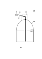
- FIG. 2 is a diagram illustrating the structure of tank equipment.
- the tank facility has a structure in which a chamber 300 is connected to an upper portion of an LNG tank 200.
- the chamber 300 is provided for the purpose of preventing leakage and scattering of LNG and boil-off gas into the atmosphere.
- LNG is stored in the LNG tank 200.
- the LNG tank 200 and the chamber 300 are provided with a portion communicating with each other. Although the communicating place is sealed with a flange or the like, the LNG boil-off gas may leak from the LNG tank 200 to the chamber 300 through the communicating place.
- a supply means for supplying an inert gas such as nitrogen gas to the chamber 300 is provided.
- the interior of the chamber 300 is purged by supplying the inert gas into the chamber 300.
- a vibration type liquid density meter as a sensor for measuring the liquid density distribution. Since the height of the tank is about 40 to 50 m, it is desired that the length of 40 to 50 m can be measured.
- the vibrating liquid densitometer needs to be sampled, so that it is difficult to perform continuous measurement spatially and temporally. Further, in the measurement work, a cable or the like for signal acquisition needs to be flexible.
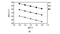
- FIG. 3 is a diagram illustrating the relationship between the liquid density of LNG and the temperature. As illustrated in FIG. 3, the liquid density of LNG and the temperature have a close relationship. Note that FIG. 3 exemplifies the relationship between the liquid densities of LNG of types A to C and the temperature.
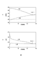
- FIG. 4A is a diagram illustrating changes over time in the liquid densities of the upper and lower layers in the LNG tank 200.
- FIG.4(b) is a figure which illustrates the time-dependent change of the temperature of the said upper layer and the said lower layer.
- the liquid density of the upper layer and the liquid density of the lower layer are close to each other before the rollover occurs, and the liquid density of the upper layer and the liquid density of the lower layer become close to each other at the time of the rollover. It almost agrees.
- FIG. 4B the temperature of the upper layer and the temperature of the lower layer become close to each other before the rollover occurs, and the temperature of the upper layer and the temperature of the lower layer substantially match at the time of the rollover. There is. From the above, it is considered that the occurrence of rollover can be estimated by measuring the temperature change with time using a temperature sensor.
- FIG. 5 is a schematic diagram of the temperature measurement system 100 according to the first embodiment.
- the temperature measurement system 100 includes a temperature measurement device 10, an optical fiber 20, and the like.
- the optical fiber 20 is introduced into the chamber 300 from the outside of the chamber 300 through the seal flange 301 of the chamber 300. Further, the optical fiber 20 is introduced into the LNG tank 200 through a seal flange 302 provided at a communication part between the chamber 300 and the LNG tank 200.
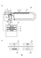
- FIG. 6A is a schematic diagram showing the overall configuration of the temperature measuring device 10.
- the temperature measuring device 10 includes a measuring machine 30, a control unit 40, and the like.
- the measuring machine 30 includes a laser 31, a beam splitter 32, an optical switch 33, a filter 34, a plurality of detectors 35a and 35b, and the like.
- the control unit 40 includes an instruction unit 41, a temperature measurement unit 42, a determination unit 43, and the like.
- FIG. 6B is a block diagram for explaining the hardware configuration of the control unit 40.
- the control unit 40 includes a CPU 101, a RAM 102, a storage device 103, an interface 104 and the like. Each of these devices is connected by a bus or the like.
- a CPU (Central Processing Unit) 101 is a central processing unit.
- the CPU 101 includes one or more cores.
- a RAM (Random Access Memory) 102 is a volatile memory that temporarily stores a program executed by the CPU 101, data processed by the CPU 101, and the like.
- the storage device 103 is a non-volatile storage device.
- the storage device 103 for example, a ROM (Read Only Memory), a solid state drive (SSD) such as a flash memory, a hard disk driven by a hard disk drive, or the like can be used.
- the control unit 40 realizes the instruction unit 41, the temperature measurement unit 42, the determination unit 43, and the like.
- the instruction unit 41, the temperature measurement unit 42, the determination unit 43, and the like may be hardware such as a dedicated circuit.
- the laser 31 is a light source such as a semiconductor laser, and emits laser light in a predetermined wavelength range according to an instruction from the instruction unit 41.
- the laser 31 emits a light pulse (laser pulse) at a predetermined time interval.
- the beam splitter 32 causes the optical pulse emitted from the laser 31 to enter the optical switch 33.
- the optical switch 33 is a switch that switches the emission destination (channel) of the incident optical pulse. The optical switch 33 alternately injects an optical pulse into the first end of the optical fiber 20 at a constant cycle in accordance with an instruction from the instruction unit 41.
- the optical pulse incident on the optical fiber 20 propagates through the optical fiber 20.
- the optical pulse is gradually attenuated while propagating in the optical fiber 20 while generating forward scattered light propagating in the propagation direction and backward scattered light (return light) propagating in the return direction.
- the backscattered light passes through the optical switch 33 and enters the beam splitter 32 again.
- the backscattered light that has entered the beam splitter 32 is emitted to the filter 34.
- the filter 34 is a WDM coupler or the like, and extracts the long-wavelength component (Stokes component described below) and the short-wavelength component (anti-Stokes component described below) from the backscattered light.
- the detectors 35a and 35b are light receiving elements.
- the detector 35 a converts the received light intensity of the short wavelength component of the backscattered light into an electric signal and sends it to the temperature measuring unit 42.
- the detector 35b converts the received light intensity of the long wavelength component of the backscattered light into an electric signal and sends it to the temperature measuring unit 42.
- the temperature measuring unit 42 measures the temperature distribution in the extending direction of the optical fiber 20 using the Stokes component and the anti-Stokes component.
- the determination unit 43 determines whether or not a rollover will occur based on the temperature distribution measured by the temperature measurement unit 42, and estimates the time or the like at which the rollover will occur.
- FIG. 7 is a diagram showing the components of the backscattered light. As illustrated in FIG. 7, backscattered light is roughly classified into three types. These three types of light are Rayleigh scattered light used for OTDR (optical pulse tester), Brillouin scattered light used for strain measurement, temperature measurement, etc. in order of increasing light intensity and closer to the incident light wavelength. Raman scattered light used for. The Raman scattered light is generated by the interference between light and the lattice vibration in the optical fiber 20 which changes according to the temperature. Short-wavelength components called anti-Stokes components are generated by the constructive interference, and long-wavelength components called Stokes components are produced by the constructive interference.
- OTDR optical pulse tester
- Brillouin scattered light used for strain measurement
- temperature measurement temperature measurement
- Raman scattered light used for.
- the Raman scattered light is generated by the interference between light and the lattice vibration in the optical fiber 20 which changes according to the temperature. Short-wavelength components called anti-Stokes components are generated by the constructive interference, and long-wavelength components
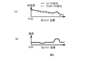
- FIG. 8A shows the elapsed time after the light pulse is emitted by the laser 31, the Stokes component (long wavelength component), and the anti-Stokes component (short wavelength component) when light is incident from the first end of the optical fiber 20. It is a figure which illustrates the relationship with light intensity.
- the elapsed time corresponds to the propagation distance in the optical fiber 20 (position in the optical fiber 20).
- the light intensities of the Stokes component and the anti-Stokes component both decrease with the elapsed time. This is because the light pulse gradually attenuates and propagates in the optical fiber 20 while generating the forward scattered light and the back scattered light.
- the light intensity of the anti-Stokes component is higher than that of the Stokes component at the position where the temperature is high in the optical fiber 20, and is higher than that of the Stokes component at the position of low temperature. Get weaker. Therefore, it is possible to detect the temperature at each position in the optical fiber 20 by detecting both components with the detectors 35a and 35b and utilizing the characteristic difference between the two components.
- the region showing the maximum is a region heated locally in the optical fiber 20.
- the region showing the minimum is a region that is locally cooled in the optical fiber 20.
- the temperature measuring unit 42 measures the temperature from the Stokes component and the anti-Stokes component for each elapsed time. Thereby, the temperature at each sampling position in the optical fiber 20 can be measured. That is, the temperature distribution in the extending direction of the optical fiber 20 can be measured. Since the characteristic difference between both components is used, the temperature can be measured with high accuracy even if the light intensities of both components are attenuated according to the distance.
- FIG. 8B shows the temperature calculated using the detection result of FIG. The horizontal axis of FIG. 8B is the position in the optical fiber 20 calculated based on the elapsed time. As illustrated in FIG. 8B, the temperature at each position in the optical fiber 20 can be measured by detecting the Stokes component and the anti-Stokes component.
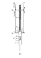
- FIG. 9 is a diagram illustrating a structure (temperature measuring structure) for protecting the optical fiber 20.
- the optical fiber 20 includes a connecting fiber 21, a fusing sleeve 22, and a measuring fiber 23.
- the first end of the connecting fiber 21 (the first end of the optical fiber 20) is connected to the temperature measuring device 10.
- the second end of the connecting fiber 21 is connected to the first end of the measuring fiber 23 via the fusion splicing sleeve 22.
- the measurement fiber 23 extends from the outside of the chamber 300 through the chamber 300 into the LNG tank 200. Therefore, the second end of the measurement fiber 23 is located inside the LNG of the LNG tank 200.
- the connecting tube 51 has flexibility and a sealing property. That is, the connecting tube 51 does not have air permeability/liquid permeability to the outside. A portion of the measuring fiber 23 that is not inserted into the connecting tube 51 is inserted into the metal flexible tube 52.
- the metal flexible tube 52 has flexibility, and has air permeability and liquid permeability to the outside.
- the connecting tube 51 and the metal flexible tube 52 are connected by an annular seal member 53.
- the seal member 53 has a sealing property.
- the measuring fiber 23 is inserted into the through hole in the seal member 54 without any gap.
- the seal member 54 is inserted into the through hole in the seal member 55 without any gap.
- the seal member 55 is inserted into the seal member 53 without a gap.
- the sealing members 53 to 55 may be located inside the chamber 300 or outside the chamber 300.
- the chamber 300 may be sealed by the seal flange 301 and the connecting tube 51.
- the seal members 53 to 55 are located outside the chamber 300, the chamber 300 may be sealed by the seal flange 301 and the metal flexible tube 52 covered with the film member 56.
- the metal flexible tube 52 is covered with a film member 56 in the chamber 300. Thereby, the metal flexible tube 52 is sealed in the chamber 300. That is, the metal flexible tube 52 does not have air permeability/liquid permeability to the outside in the chamber 300. Further, the metal flexible tube 52 has a portion which is not covered with the film member 56 inside the LNG tank 200. Therefore, the metal flexible tube 52 is not sealed inside the LNG tank 200. Ie. Inside the LNG tank 200, the metal flexible tube 52 has air permeability and liquid permeability to the outside.
- the film member 56 is a film-shaped member such as PTFE (polytetrafluoroethylene) having durability against LNG. In the seal flange 302, the metal flexible tube 52 is covered with the film member 56. In FIG. 9, a part of the metal flexible tube 52 in the chamber 300 is shown as being transparent.
- the LNG enters the metal flexible tube 52 in the LNG tank 200, so that the measurement fiber 23 comes into contact with the LNG.
- the temperature of LNG can be measured with high accuracy.
- the metal flexible tube 52 is covered with the film member 56 in the chamber 300, invasion of boil-off gas generated in the LNG tank 200 into the chamber 300 is suppressed. Thereby, leakage of LNG from the LNG tank 200 can be suppressed.
- the metal flexible tube 52 has flexibility and the optical fiber 20 also has flexibility
- the metal flexible tube 52 is not limited to the positions of the seal flange 301 and the seal flange 302, and metal from the outside of the chamber 300 to the inside of the LNG tank 200.
- the flexible tube 52 and the optical fiber 20 can be inserted.
- the optical fiber 20 has a small diameter. Further, since the optical fiber 20 does not need to be energized, no explosion-proof measure is required and no explosion-proof protective tube is required. As a result, the metal flexible tube 52 does not need to have a large diameter. For example, the diameter of the metal flexible tube 52 can be 4 inches or less. In this case, the size of the holes formed in the LNG tank 200 can be reduced. As a result, it is possible to suppress leakage and scattering of LNG and boil-off gas, and deterioration of heat insulation performance and the like.
- the optical fiber 20 and the metal flexible tube 52 are laid, it is possible to measure the temperature at a plurality of measurement points in the depth direction of the LNG without moving. For example, unlike the vibrating liquid densitometer, it is not necessary to move up and down for each sampling. Therefore, the number of times of vertically moving the optical fiber 20 and the metal flexible tube 52 can be minimized. As a result, even if the supply of the inert gas to the chamber 300 is stopped, the pressure inside the chamber 300 is stabilized. As a result, gas leakage in the chamber 300 can be suppressed.
- the efficient discharge and stirring in the LNG tank 200 can minimize the generation of boil-off gas.
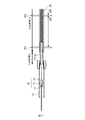
- FIG. 10 is a diagram illustrating a protective structure of the optical fiber 20 according to the second embodiment.
- the metal flexible tube 52 has a portion which is not covered with the film member 56 in the chamber 300.
- the metal flexible tube 52 is not sealed inside the chamber 300. That is, the metal flexible tube 52 has air permeability and liquid permeability to the outside in the chamber 300.
- the metal flexible tube 52 is covered with the film member 56 in the LNG tank 200. Thereby, the metal flexible tube 52 is sealed in the LNG tank 200.
- the metal flexible tube 52 does not have air permeability/liquid permeability to the outside in the LNG tank 200.
- the metal flexible tube 52 is covered with the film member 56.
- FIG. 10 a part of the metal flexible tube 52 outside the chamber 300 is shown as being transparent.
- the seal members 53 to 55 are located outside the chamber 300. Outside the chamber 300, the metal flexible tube 52 is covered with the film member 56. Further, in the seal flange 301, the metal flexible tube 52 is covered with the film member 56.
- the metal flexible tube 52 is covered with the film member 56, invasion of LNG, boil-off gas, etc. into the metal flexible tube 52 is suppressed. Also, outside the chamber 300, the seal member 53, the seal member 54, and the seal member 55 prevent boil-off gas from leaking to the outside of the chamber 300. From the above, leakage of LNG from the LNG tank 200 is suppressed.
- the dry inert gas in the chamber 300 enters the metal flexible tube 52 in the LNG tank 200 to purge the water vapor in the metal flexible tube 52. Thereby, it is possible to suppress freezing of water vapor due to the extremely low temperature of LNG.
- the film member 56 is thinned to about several tens of ⁇ m, the thermal resistance of the film member 56 can be suppressed. As a result, the difference between the LNG temperature and the temperature inside the metal flexible tube 52 becomes small. Therefore, the influence on the temperature measurement accuracy can be reduced. If helium, which has a higher thermal conductivity than nitrogen, is used as the inert gas used for purging the chamber 300, the thermal conductivity in the metal flexible tube 52 becomes high. Thereby, the influence on the temperature measurement accuracy can be further reduced.
- temperature measurement using an optical fiber enables continuous measurement in time and space, and since it does not need to be energized and explosion proof is not required, the size is reduced. As a result, it becomes easy to estimate stratification and rollover in the LNG tank 200. In addition, boil-off gas generation can be minimized by efficient discharge and stirring.
- the seal members 53 to 55 may be located inside the chamber 300.
- the chamber 300 may be sealed by the seal flange 301 and the connecting tube 51.
- FIG. 11 is a diagram illustrating a protective structure for the optical fiber 20 according to the third embodiment.
- the metal flexible tube 52 is arranged from the inside of the LNG tank 200 to the outside of the chamber 300.
- the metal flexible tube 52 is covered with a film member 56 from the inside of the LNG tank 200 to the outside of the chamber 300. Note that, in FIG. 11, a part of the metal flexible tube 52 in the chamber 300 is shown as being transparent.
- the metal flexible tube 52 is covered with the film member 56 in the LNG tank 200, the entry of LNG into the metal flexible tube 52 is suppressed. Further, since the metal flexible tube 52 is covered with the film member 56 in the chamber 300, the gas in the chamber 300 is suppressed from entering the metal flexible tube 52. Thereby, leakage of LNG from the LNG tank 200 is suppressed.
- the film member 56 is thinned to about several tens of ⁇ m, the thermal resistance of the film member 56 can be suppressed. Thereby, the influence on the temperature measurement accuracy can be reduced.
- the first end of the optical fiber 20 is connected to the temperature measuring device 10, and the second end of the optical fiber 20 is immersed in the LNG tank 200.
- the optical fiber 20 passes through the metal flexible tube 52, is folded or wound in the LNG tank 200, and further passes through the metal flexible tube 52 to the temperature measuring device 10. May be connected.
- the first end and the second end of the optical fiber 20 are connected to the optical switch 33.
- the optical switch 33 switches the emission destination (channel) of the optical pulse incident from the laser 31.
- the optical switch 33 can select the first end and the second end as the incident destination of the optical pulse to the optical fiber 20 according to the instruction of the instruction unit 41. Thereby, even if the optical fiber 20 is broken midway, the temperature can be continuously measured.
- the optical fiber is used as the temperature sensor, but the temperature sensor is not limited thereto.
- a thermocouple or the like can be used. Since the thermocouple is made of a metal wire, it has flexibility.
- the metal flexible tube 52 may move or float in the LNG. Therefore, a weight may be provided at the lower end of the metal flexible tube 52.
- temperature measuring device 10 temperature measuring device 20 optical fiber 21 connecting fiber 22 fusion splicing 23 measuring fiber 30 measuring machine 40 control unit 42 temperature measuring unit 51 connecting tube 52 metal flexible tube 53 to 55 sealing member 56 film member 100 temperature measuring system
Landscapes
- Engineering & Computer Science (AREA)
- Mechanical Engineering (AREA)
- General Engineering & Computer Science (AREA)
- Filling Or Discharging Of Gas Storage Vessels (AREA)
- Measuring Temperature Or Quantity Of Heat (AREA)
Abstract
温度測定構造は、LNGが貯蔵されたLNGタンクに接続されたチャンバから前記LNGタンク内まで延びる金属可撓管と、前記金属可撓管内に挿入され、可撓性を有する温度センサと、を備え、前記金属可撓管は、前記LNGタンク内では通気・通液性を有する箇所があり、前記チャンバ内では外部に対して通気・通液性を有していない。
Description
本件は、温度測定構造および温度測定システムに関する。
LNGタンクに貯蔵されているLNGの温度測定を行う技術として、光ファイバのような可撓性を有する温度センサを用いる温度測定技術が開示されている(例えば、特許文献1参照)。光ファイバを保護する構造として、通気性のある網状管や蛇腹管を用いる技術が開示されている(例えば、特許文献2参照)。
LNGタンクに温度センサを挿入する場合には、LNGタンクに接続されたチャンバからLNGタンク内に温度センサが挿入される。この場合、通気性がある保護管で温度センサを保護しようとすると、保護管を介してLNGタンクからLNGが漏洩するおそれがある。
1つの側面では、本件は、LNGタンクからのLNGの漏洩を抑制することができる温度測定構造および温度測定システムを提供することを目的とする。
1つの態様では、温度測定構造は、LNGが貯蔵されたLNGタンクに接続されたチャンバから前記LNGタンク内まで延びる金属可撓管と、前記金属可撓管内に挿入され、可撓性を有する温度センサと、を備え、前記金属可撓管は、前記LNGタンク内では通気・通液性を有する箇所があり、前記チャンバ内では外部に対して通気・通液性を有していない。
他の態様では、温度測定構造は、LNGが貯蔵されたLNGタンクに接続されたチャンバから前記LNGタンク内まで延びる金属可撓管と、前記金属可撓管内に挿入され、可撓性を有する温度センサと、を備え、前記金属可撓管は、前記チャンバ内では通気・通液性を有する箇所があり、前記LNGタンク内では外部に対して通気・通液性を有していない。
他の態様では、温度測定構造は、LNGが貯蔵されたLNGタンクと接続されたチャンバから前記LNGタンク内まで延びる金属可撓管と、前記金属可撓管内に挿入され、可撓性を有する温度センサと、を備え、前記金属可撓管は、前記チャンバ内および前記LNGタンク内において、外部に対して通気・通液性を有していない。
他の態様では、温度測定システムは、上記いずれかの温度測定構造と、前記温度センサの検出結果から、前記LNGタンク内の温度を測定する温度測定装置と、を備える。
LNGタンクからのLNGの漏洩を抑制することができる。
実施例の説明に先立って、LNGタンクにおけるロールオーバーの概要について説明する。図1(a)で例示するように、LNGタンク200には、LNGが貯蔵されている。効率化のため、様々な産地から密度の異なるLNGがLNGタンク200に貯蔵されることが求められている。例えば、LNGタンク200には、複数の船からLNGが受け入れられることがある。この場合、成分が異なるLNGが受け入れられるため、LNGタンク200内において、LNGの成分差に基づく密度差に起因して、LNGが多層状化する。図1(a)の例では、LNGタンク200内のLNGが2層化している。図1(b)で例示するように、下層は、密度の高いLNG成分である。上層は、密度の低いLNG成分である。
この状態で、図1(a)で例示するように、LNGタンク200に熱が入ると、各層において対流(二重対流)が生じる。二重対流が生じると、上層と下層との境界を介して、各成分と熱とが少しずつ移動する。それにより、上層の密度と下層の密度とが次第に近づく。また、上層からのボイルオフガス(BOG)の発生によっても、上層の密度と下層の密度とが次第に近づく。上層の密度と下層の密度との差が小さくなると、上層と下層とが混合され、急激な対流が生じる(ロールオーバー)。
2層化されていた状態では、上層のLNG成分の存在によって、下層のLNG成分からのボイルオフガスの発生は抑圧されている。しかしながら、図1(c)で例示するように、ロールオーバー時には、下層のLNG成分が上層へ移動するため、それまで抑圧されていた大量のボイルオフガスが発生し、LNGタンク200内の圧力が異常に上昇する。なお、図1(c)において、縦軸は、ボイルオフガス量を示す。
次に、LNGタンク200を含むタンク設備について説明する。図2は、タンク設備の構造を例示する図である。図2で例示するように、タンク設備は、LNGタンク200の上部にチャンバ300が接続された構造を有する。チャンバ300は、LNGやボイルオフガスの大気への漏洩・飛散防止といった用途のために設けられている。上述したように、LNGタンク200内には、LNGが貯蔵されている。LNGタンク200とチャンバ300とは、互いに連通する箇所が備わっている。連通する箇所にはフランジなどでシールされているものの、この連通する箇所を介してLNGのボイルオフガスがLNGタンク200からチャンバ300に漏れ出すことがある。
そこで、チャンバ300内のボイルオフガスをパージするため、チャンバ300に窒素ガスなどの不活性ガスを供給する供給手段が設けられている。チャンバ300内に不活性ガスが供給されることにより、チャンバ300内がパージされる。
ロールオーバー防止のためにはLNGタンク200の深さ方向の液密度分布を把握し、LNGタンク200内を攪拌することが好ましい。センサをLNGタンク200内に挿入する箇所からボイルオフガスが漏洩するおそれがあることから、図2で例示したタンク設備では、チャンバ300からセンサを挿入してLNGタンク200のLNG内に漬けることが求められる。
例えば、液密度分布を測定するためのセンサとして、振動式液密度計を用いることが考えられる。タンクの高さは40~50m程度であるため、40~50mの長さについて測定ができることが望まれる。しかしながら、振動式液密度計は、サンプリングの必要があるため、空間的、時間的に連続した測定が困難である。また、測定作業において、信号取得のためのケーブル等に可撓性が必要となってくる。
以上のことから、振動式液密度計以外のセンサを用いて、LNGタンク200に貯蔵されているLNGの液密度を測定することが望まれる。そこで、LNGの液密度と温度との関係に着目する。図3は、LNGの液密度と温度との関係を例示する図である。図3で例示するように、LNGの液密度と温度とは、密接な関係を有している。なお、図3では、種類A~CのLNGの液密度と温度との関係が例示されている。
次に、図4(a)は、LNGタンク200内の上層および下層の液密度の経時変化を例示する図である。図4(b)は、当該上層および下層の温度の経時変化を例示する図である。図4(a)で例示するように、ロールオーバーが発生するまでに、上層の液密度と下層の液密度とが互いに近くなり、ロールオーバー発生時点で上層の液密度と下層の液密度とが略一致している。図4(b)で例示するように、ロールオーバーが発生するまでに、上層の温度と下層の温度とが互いに近くなり、ロールオーバー発生時点で上層の温度と下層の温度とが略一致している。以上のことから、温度センサを用いて温度の経時変化を測定することで、ロールオーバーの発生を推定できると考えられる。
そこで、以下の実施例では、LNGタンクからのLNGガスの漏洩を抑制しつつLNGの温度を測定することができる温度測定構造および温度測定システムについて説明する。
図5は、実施例1に係る温度測定システム100の概略図である。図5で例示するように、温度測定システム100は、温度測定装置10、光ファイバ20などを備える。光ファイバ20は、チャンバ300の外部からチャンバ300のシールフランジ301を通ってチャンバ300内に導入される。さらに、光ファイバ20は、チャンバ300とLNGタンク200との連通部に設けられたシールフランジ302を通ってLNGタンク200内に導入される。
図6(a)は、温度測定装置10の全体構成を表す概略図である。図6(a)で例示するように、温度測定装置10は、測定機30、制御部40などを備える。測定機30は、レーザ31、ビームスプリッタ32、光スイッチ33、フィルタ34、複数の検出器35a,35bなどを備える。制御部40は、指示部41、温度測定部42、判定部43などを備える。
図6(b)は、制御部40のハードウェア構成を説明するためのブロック図である。図6(b)で例示するように、制御部40は、CPU101、RAM102、記憶装置103、インタフェース104などを備える。これらの各機器は、バスなどによって接続されている。CPU(Central Processing Unit)101は、中央演算処理装置である。CPU101は、1以上のコアを含む。RAM(Random Access Memory)102は、CPU101が実行するプログラム、CPU101が処理するデータなどを一時的に記憶する揮発性メモリである。記憶装置103は、不揮発性記憶装置である。記憶装置103として、例えば、ROM(Read Only Memory)、フラッシュメモリなどのソリッド・ステート・ドライブ(SSD)、ハードディスクドライブに駆動されるハードディスクなどを用いることができる。CPU101が記憶装置103に記憶されている温度測定プログラムを実行することによって、制御部40に指示部41、温度測定部42、判定部43などが実現される。なお、指示部41、温度測定部42、判定部43などは、専用の回路などのハードウェアであってもよい。
レーザ31は、半導体レーザなどの光源であり、指示部41の指示に従って所定の波長範囲のレーザ光を出射する。本実施形態においては、レーザ31は、所定の時間間隔で光パルス(レーザパルス)を出射する。ビームスプリッタ32は、レーザ31が出射した光パルスを光スイッチ33に入射する。光スイッチ33は、入射された光パルスの出射先(チャネル)を切り替えるスイッチである。光スイッチ33は、指示部41の指示に従って、光ファイバ20の第1端に一定周期で交互に光パルスを入射する。
光ファイバ20に入射した光パルスは、光ファイバ20を伝搬する。光パルスは、伝搬方向に進行する前方散乱光および帰還方向に進行する後方散乱光(戻り光)を生成しながら徐々に減衰して光ファイバ20内を伝搬する。後方散乱光は、光スイッチ33を通過してビームスプリッタ32に再度入射する。ビームスプリッタ32に入射した後方散乱光は、フィルタ34に対して出射される。フィルタ34は、WDMカプラなどであり、後方散乱光を長波長成分(後述するストークス成分)と短波長成分(後述するアンチストークス成分)とを抽出する。検出器35a,35bは、受光素子である。検出器35aは、後方散乱光の短波長成分の受光強度を電気信号に変換して温度測定部42に送信する。検出器35bは、後方散乱光の長波長成分の受光強度を電気信号に変換して温度測定部42に送信する。温度測定部42は、ストークス成分およびアンチストークス成分を用いて、光ファイバ20の延伸方向の温度分布を測定する。判定部43は、温度測定部42が測定した温度分布に基づいて、ロールオーバーが発生するか否かを判定し、ロールオーバーが発生する時期などを推測する。
図7は、後方散乱光の成分を表す図である。図7で例示するように、後方散乱光は、大きく3種類に分類される。これら3種類の光は、光強度の高い順かつ入射光波長に近い順に、OTDR(光パルス試験器)などに使用されるレイリー散乱光、歪測定などに使用されるブリルアン散乱光、温度測定などに使用されるラマン散乱光である。ラマン散乱光は、温度に応じて変化する光ファイバ20内の格子振動と光との干渉で生成される。強めあう干渉によりアンチストークス成分と呼ばれる短波長成分が生成され、弱めあう干渉によりストークス成分とよばれる長波長成分が生成される。
図8(a)は、光ファイバ20の第1端から光入射した場合において、レーザ31による光パルス発光後の経過時間と、ストークス成分(長波長成分)およびアンチストークス成分(短波長成分)の光強度との関係を例示する図である。経過時間は、光ファイバ20における伝搬距離(光ファイバ20における位置)に対応している。図8(a)で例示するように、ストークス成分およびアンチストークス成分の光強度は、両方とも経過時間とともに低減する。これは、光パルスが前方散乱光および後方散乱光を生成しながら徐々に減衰して光ファイバ20内を伝搬することに起因する。
図8(a)で例示するように、アンチストークス成分の光強度は光ファイバ20において高温になる位置では、ストークス成分と比較してより強くなり、低温になる位置では、ストークス成分と比較してより弱くなる。したがって、両成分を検出器35a,35bで検出し、両成分の特性差を利用することによって、光ファイバ20内の各位置の温度を検出することができる。なお、図8(a)において、極大を示す領域は、光ファイバ20において局所的に加熱された領域である。また、極小を示す領域は、光ファイバ20において局所的に冷却された領域である。
本実施例においては、温度測定部42は、経過時間ごとにストークス成分とアンチストークス成分とから温度を測定する。それにより、光ファイバ20内における各サンプリング位置の温度を測定することができる。すなわち、光ファイバ20の延伸方向における温度分布を測定することができる。なお、両成分の特性差を利用することから、距離に応じて両成分の光強度が減衰しても、高精度で温度を測定することができる。図8(b)は、図8(a)の検出結果を用いて算出した温度である。図8(b)の横軸は、経過時間を基に算出した光ファイバ20内の位置である。図8(b)で例示するように、ストークス成分およびアンチストークス成分を検出することによって、光ファイバ20内の各位置の温度を測定することができる。
図9は、光ファイバ20を保護する構造(温度測定構造)を例示する図である。図9で例示するように、光ファイバ20は、接続用ファイバ21、融着スリーブ22および測定用ファイバ23を備える。接続用ファイバ21の第1端(光ファイバ20の第1端)は、温度測定装置10に接続されている。接続用ファイバ21の第2端は、融着スリーブ22を介して測定用ファイバ23の第1端に接続されている。測定用ファイバ23は、チャンバ300外からチャンバ300を通ってLNGタンク200内に延びている。したがって、測定用ファイバ23の第2端は、LNGタンク200のLNG内に位置している。
接続用ファイバ21、融着スリーブ22、および測定用ファイバ23の第1端近傍は、接続用チューブ51内に挿入されている。接続用チューブ51は、可撓性を有するとともに、シール性を有している。すなわち、接続用チューブ51は、外部に対して通気・通液性を有していない。測定用ファイバ23のうち接続用チューブ51内に挿入されていない部分は、金属可撓管52に挿入されている。金属可撓管52は、可撓性を有するとともに、外部に対して通気性および通液性を有している。
接続用チューブ51と金属可撓管52とは、環状のシール部材53によって接続されている。シール部材53は、シール性を有している。シール部材53内において、測定用ファイバ23は、シール部材54内の貫通孔に隙間なく挿通されている。シール部材54は、シール部材55内の貫通孔に隙間なく挿通されている。シール部材55は、シール部材53に隙間なく挿通されている。以上の構造により、接続用チューブ51と金属可撓管52とは、互いにシールされている。
シール部材53~55は、チャンバ300内に位置していてもよく、チャンバ300外に位置していてもよい。シール部材53~55がチャンバ300内に位置している場合には、シールフランジ301と接続用チューブ51とによってチャンバ300がシールされていればよい。シール部材53~55がチャンバ300外に位置している場合には、シールフランジ301と、フィルム部材56によって覆われた金属可撓管52と、によってチャンバ300がシールされていればよい。
金属可撓管52は、チャンバ300内では、フィルム部材56によって覆われている。それにより、金属可撓管52は、チャンバ300内ではシールされている。すなわち、金属可撓管52は、チャンバ300内では、外部に対して通気・通液性を有していない。また、金属可撓管52は、LNGタンク200の内部ではフィルム部材56によって覆われていない箇所がある。それにより、金属可撓管52は、LNGタンク200の内部ではシールされていない。すなわち。金属可撓管52は、LNGタンク200の内部では、外部に対して通気・通液性を有している。フィルム部材56は、LNGに耐久性を有するPTFE(ポリテトラフルオロエチレン)などのフィルム状部材である。なお、シールフランジ302では、金属可撓管52は、フィルム部材56によって覆われている。なお、図9では、チャンバ300内の金属可撓管52の一部を透過して例示してある。
本実施例においては、LNGタンク200内では金属可撓管52内にLNGが侵入するため、測定用ファイバ23がLNGと接触する。それにより、高精度にLNGの温度を測定することができる。一方、チャンバ300内においては金属可撓管52がフィルム部材56によって覆われていることから、LNGタンク200で発生するボイルオフガスの、チャンバ300内への侵入が抑制される。それにより、LNGタンク200からのLNGの漏洩を抑制することができる。
また、金属可撓管52が可撓性を有するとともに光ファイバ20も可撓性を有することから、シールフランジ301およびシールフランジ302の位置に制限されず、チャンバ300外からLNGタンク200内に金属可撓管52および光ファイバ20を挿入することができる。
また、光ファイバ20が小径を有している。また、光ファイバ20は、通電の必要がないことから防爆対策が不要であって、防爆用の保護管が必要ない。それにより、金属可撓管52にも大きい径が必要とされない。例えば、金属可撓管52の径を4インチ以下とすることができる。この場合、LNGタンク200に空ける孔のサイズを小さくすることができる。それにより、LNGやボイルオフガスの漏洩および飛散、ならびに断熱性能等の低下を抑制することができる。
また、光ファイバ20および金属可撓管52は、一旦敷設すれば、移動させることなくLNGの深さ方向の複数測定点の温度測定が可能である。例えば、振動式液密度計のように、サンプリングのたびに上下動させる必要がない。したがって、光ファイバ20および金属可撓管52を上下動させる回数を最低限度にとどめることができる。その結果、チャンバ300に対する不活性ガス供給を停止しても、チャンバ300内の圧力が安定化する。その結果、チャンバ300内のガスの漏洩を抑制することができる。
また、光ファイバ20を用いれば複数測定点の温度測定が可能であることから、深さ方向に連続した測定点での測定や経時変化を調査することが可能となる。したがって、LNGタンク200内の層状化やロールオーバーの推定が容易となる。また、LNGタンク200内における効率的な払出や攪拌により、ボイルオフガスの発生を最小化することができる。
金属可撓管52においてフィルム部材56によって覆われている箇所は、実施例1の箇所に限定されない。実施例2では、実施例1に対して、金属可撓管52において、フィルム部材56によって覆われている箇所を変更してある。図10は、実施例2に係る光ファイバ20の保護構造を例示する図である。図10で例示するように、金属可撓管52は、チャンバ300内においてはフィルム部材56によって覆われていない箇所がある。それにより、金属可撓管52は、チャンバ300内ではシールされていない。すなわち、金属可撓管52は、チャンバ300内では、外部に対して通気・通液性を有している。一方、金属可撓管52は、LNGタンク200内においては、フィルム部材56によって覆われている。それにより、金属可撓管52は、LNGタンク200内ではシールされている。すなわち、金属可撓管52は、LNGタンク200内では、外部に対して通気・通液性を有していない。なお、シールフランジ302においては、金属可撓管52は、フィルム部材56によって覆われている。なお、図10では、チャンバ300外の金属可撓管52の一部を透過して例示してある。
本実施例においては、シール部材53~55は、チャンバ300外に位置している。チャンバ300外においては、金属可撓管52は、フィルム部材56によって覆われている。また、シールフランジ301においては、金属可撓管52は、フィルム部材56によって覆われている。
LNGタンク200内においては、金属可撓管52がフィルム部材56によって覆われていることから、金属可撓管52内へのLNG、ボイルオフガスなどの侵入が抑制される。また、チャンバ300の外側においても、シール部材53、シール部材54およびシール部材55によって、チャンバ300外へのボイルオフガスの漏洩が抑制される。以上のことから、LNGタンク200からのLNGの漏洩が抑制される。
一方、チャンバ300内においては、金属可撓管52はフィルム部材56によって覆われていない箇所がある。それにより、チャンバ300内の乾燥した不活性ガスがLNGタンク200内の金属可撓管52内に侵入し、金属可撓管52内の水蒸気をパージする。それにより、LNGの極低温に起因する水蒸気の凍結を抑制することができる。
なお、フィルム部材56を数十μm程度と薄くすれば、フィルム部材56の熱抵抗を抑制することができる。それにより、LNGの温度と、金属可撓管52内の温度との差が小さくなる。したがって、温度測定精度への影響を小さくすることができる。なお、チャンバ300内のパージに用いる不活性ガスとして、窒素よりも高い熱伝導率を有するヘリウムを用いれば、金属可撓管52内の熱伝導性が高くなる。それにより、温度測定精度への影響をより小さくすることができる。
また、光ファイバによる温度測定では、時間的および空間的に連続した測定が可能であり、通電の必要がなく防爆不要であるためサイズが小さくなる。その結果、LNGタンク200内の層状化やロールオーバーの推定が容易となる。また、効率的な払出や攪拌により、ボイルオフガスの発生を最小化することができる。
なお、シール部材53~55は、チャンバ300内に位置していてもよい。シール部材53~55がチャンバ300内に位置している場合には、シールフランジ301と接続用チューブ51とによってチャンバ300がシールされていればよい。
実施例3では、実施例1および実施例2に対して、金属可撓管52において、フィルム部材56によって覆われている箇所を変更してある。図11は、実施例3に係る光ファイバ20の保護構造を例示する図である。図11で例示するように、金属可撓管52は、LNGタンク200内からチャンバ300外にかけて配置されている。また、金属可撓管52は、LNGタンク200内からチャンバ300外にかけてフィルム部材56によって覆われている。なお、図11では、チャンバ300内の金属可撓管52の一部を透過して例示してある。
本実施例においては、金属可撓管52がLNGタンク200内でフィルム部材56によって覆われていることから、金属可撓管52へのLNGの侵入が抑制される。また、金属可撓管52がチャンバ300内でフィルム部材56によって覆われていることから、チャンバ300内のガスが金属可撓管52に侵入することが抑制される。それにより、LNGタンク200からのLNGの漏洩が抑制される。
なお、フィルム部材56を数十μm程度と薄くすれば、フィルム部材56の熱抵抗を抑制することができる。それにより、温度測定精度への影響を小さくすることができる。
実施例1~実施例3では、光ファイバ20の第1端は温度測定装置10に接続され、光ファイバ20の第2端はLNGタンク200内に浸漬されている。しかしながら、図12で例示するように、光ファイバ20は、金属可撓管52を通って、LNGタンク200内で折り返してまたは捲回され、さらに金属可撓管52を通って温度測定装置10に接続されてもよい。具体的には、光ファイバ20の第1端および第2端が光スイッチ33に接続されている。光スイッチ33は、レーザ31から入射された光パルスの出射先(チャネル)を切り替える。ダブルエンド方式では、光スイッチ33は、指示部41の指示に従って、光ファイバ20への光パルスの入射先として、第1端および第2端を選択することができる。それにより、光ファイバ20が途中で破断しても、継続して温度測定が可能である。
(他の例)
上記各例では、温度センサとして光ファイバを用いたが、それに限られない。例えば、熱電対などを用いることもできる。熱電対は、金属線からなるため、可撓性を有している。
上記各例では、温度センサとして光ファイバを用いたが、それに限られない。例えば、熱電対などを用いることもできる。熱電対は、金属線からなるため、可撓性を有している。
また、金属可撓管52に重さが足りない場合には、金属可撓管52がLNG内で移動または浮遊するおそれがある。そこで、金属可撓管52の下端に錘を設けてもよい。
以上、本発明の実施例について詳述したが、本発明は係る特定の実施例に限定されるものではなく、特許請求の範囲に記載された本発明の要旨の範囲内において、種々の変形・変更が可能である。
10 温度測定装置
20 光ファイバ
21 接続用ファイバ
22 融着スリーブ
23 測定用ファイバ
30 測定機
40 制御部
42 温度測定部
51 接続用チューブ
52 金属可撓管
53~55 シール部材
56 フィルム部材
100 温度測定システム
20 光ファイバ
21 接続用ファイバ
22 融着スリーブ
23 測定用ファイバ
30 測定機
40 制御部
42 温度測定部
51 接続用チューブ
52 金属可撓管
53~55 シール部材
56 フィルム部材
100 温度測定システム
Claims (9)
- LNGが貯蔵されたLNGタンクに接続されたチャンバから前記LNGタンク内まで延びる金属可撓管と、
前記金属可撓管内に挿入され、可撓性を有する温度センサと、を備え、
前記金属可撓管は、前記LNGタンク内では通気・通液性を有する箇所があり、前記チャンバ内では外部に対して通気・通液性を有していないことを特徴とする温度測定構造。 - LNGが貯蔵されたLNGタンクに接続されたチャンバから前記LNGタンク内まで延びる金属可撓管と、
前記金属可撓管内に挿入され、可撓性を有する温度センサと、を備え、
前記金属可撓管は、前記チャンバ内では通気・通液性を有する箇所があり、前記LNGタンク内では外部に対して通気・通液性を有していないことを特徴とする温度測定構造。 - LNGが貯蔵されたLNGタンクと接続されたチャンバから前記LNGタンク内まで延びる金属可撓管と、
前記金属可撓管内に挿入され、可撓性を有する温度センサと、を備え、
前記金属可撓管は、前記チャンバ内および前記LNGタンク内において、外部に対して通気・通液性を有していないことを特徴とする温度測定構造。 - 前記温度センサは、光ファイバであることを特徴とする請求項1~3のいずれか一項に記載の温度測定構造。
- 前記金属可撓管が外部に対して通気・通液性を有していない箇所では、前記金属可撓管は、フィルム部材によって覆われていることを特徴とする請求項1~4のいずれか一項に記載の温度測定構造。
- 前記フィルム部材は、PTFEであることを特徴とする請求項5記載の温度測定構造。
- 前記チャンバに供給されるパージガスは、窒素またはヘリウムであることを特徴とする請求項1~6のいずれか一項に記載の温度測定構造。
- 請求項1~7のいずれか一項に記載の温度測定構造と、
前記温度センサの検出結果から、前記LNGタンク内の温度を測定する温度測定装置と、を備えることを特徴とする温度測定システム。 - 前記温度測定装置の測定結果を用いて、前記LNGタンクのロールオーバーの発生時期を予測する予測部を備えることを特徴とする請求項8記載の温度測定システム。
Priority Applications (2)
| Application Number | Priority Date | Filing Date | Title |
|---|---|---|---|
| PCT/JP2018/047762 WO2020136740A1 (ja) | 2018-12-26 | 2018-12-26 | 温度測定構造および温度測定システム |
| JP2020562004A JP7115565B2 (ja) | 2018-12-26 | 2018-12-26 | 温度測定構造および温度測定システム |
Applications Claiming Priority (1)
| Application Number | Priority Date | Filing Date | Title |
|---|---|---|---|
| PCT/JP2018/047762 WO2020136740A1 (ja) | 2018-12-26 | 2018-12-26 | 温度測定構造および温度測定システム |
Publications (1)
| Publication Number | Publication Date |
|---|---|
| WO2020136740A1 true WO2020136740A1 (ja) | 2020-07-02 |
Family
ID=71129287
Family Applications (1)
| Application Number | Title | Priority Date | Filing Date |
|---|---|---|---|
| PCT/JP2018/047762 Ceased WO2020136740A1 (ja) | 2018-12-26 | 2018-12-26 | 温度測定構造および温度測定システム |
Country Status (2)
| Country | Link |
|---|---|
| JP (1) | JP7115565B2 (ja) |
| WO (1) | WO2020136740A1 (ja) |
Citations (4)
| Publication number | Priority date | Publication date | Assignee | Title |
|---|---|---|---|---|
| JPH04184229A (ja) * | 1990-11-20 | 1992-07-01 | Fujikura Ltd | 温度センサおよびその製造方法 |
| JPH11141799A (ja) * | 1997-11-13 | 1999-05-28 | Ishikawajima Harima Heavy Ind Co Ltd | シース型測温抵抗体の据付工法 |
| JP2000120920A (ja) * | 1998-10-09 | 2000-04-28 | Ishikawajima Harima Heavy Ind Co Ltd | 弁の交換装置 |
| JP2015124860A (ja) * | 2013-12-27 | 2015-07-06 | 三菱重工業株式会社 | 低温液化ガスの貯蔵システム |
Family Cites Families (3)
| Publication number | Priority date | Publication date | Assignee | Title |
|---|---|---|---|---|
| JP4706475B2 (ja) | 2005-12-28 | 2011-06-22 | 日立電線株式会社 | 光学式センサを用いた測定方法 |
| JP5227635B2 (ja) | 2008-03-28 | 2013-07-03 | 古河電気工業株式会社 | 流体漏洩検知システム |
| JP6561747B2 (ja) | 2015-10-05 | 2019-08-21 | 富士通株式会社 | 温度測定装置、温度測定方法および温度測定プログラム |
-
2018
- 2018-12-26 WO PCT/JP2018/047762 patent/WO2020136740A1/ja not_active Ceased
- 2018-12-26 JP JP2020562004A patent/JP7115565B2/ja not_active Expired - Fee Related
Patent Citations (4)
| Publication number | Priority date | Publication date | Assignee | Title |
|---|---|---|---|---|
| JPH04184229A (ja) * | 1990-11-20 | 1992-07-01 | Fujikura Ltd | 温度センサおよびその製造方法 |
| JPH11141799A (ja) * | 1997-11-13 | 1999-05-28 | Ishikawajima Harima Heavy Ind Co Ltd | シース型測温抵抗体の据付工法 |
| JP2000120920A (ja) * | 1998-10-09 | 2000-04-28 | Ishikawajima Harima Heavy Ind Co Ltd | 弁の交換装置 |
| JP2015124860A (ja) * | 2013-12-27 | 2015-07-06 | 三菱重工業株式会社 | 低温液化ガスの貯蔵システム |
Also Published As
| Publication number | Publication date |
|---|---|
| JPWO2020136740A1 (ja) | 2021-09-27 |
| JP7115565B2 (ja) | 2022-08-09 |
Similar Documents
| Publication | Publication Date | Title |
|---|---|---|
| JP7378538B2 (ja) | 測定ウェハ装置 | |
| JP6816969B2 (ja) | 海底ケーブルを監視するための方法および装置 | |
| EP1315976B1 (en) | Thermographic wiring inspection | |
| US20060250683A1 (en) | Transformer temperature monitoring and control | |
| US7762743B2 (en) | Distributed temperature sensing in a remotely operated vehicle umbilical fiber optic cable | |
| KR20200014751A (ko) | 단열재 제거 없는 cui 검사를 위한 마이크로파 혼 안테나 기반 트랜스듀서 시스템 | |
| JP6483806B2 (ja) | ファイバーオプティクスを用いて行うパイプラインの完全性の監視 | |
| US20060251147A1 (en) | Transformer temperature monitoring and control | |
| US6995565B1 (en) | Thermographic wiring inspection | |
| JP5865614B2 (ja) | 原子力発電所の水位温度検出装置 | |
| JP2002048898A (ja) | キャスク用モニタリング装置 | |
| WO2020136740A1 (ja) | 温度測定構造および温度測定システム | |
| US20200116574A1 (en) | Temperature measurement apparatus, temperature measurement method, and non-transitory computer-readable storage medium for storing temperature measurement program | |
| JP7364960B2 (ja) | 光ファイバ装置、温度測定システム、および光ファイバ装置の製造方法 | |
| JP2011179916A (ja) | 漏洩監視装置 | |
| KR101463444B1 (ko) | 원자로 용기 헤드의 냉각재 누설 검지 장치 및 이를 이용한 냉각재 누설 검지 방법 | |
| CN106781193A (zh) | 分区时分型光栅阵列光纤线型感温火灾探测系统及方法 | |
| FR2733080A1 (fr) | Procede et dispositif de detection et de surveillance du percement du fond de la cuve d'un reacteur nucleaire | |
| Kasinathan et al. | Fiber optic sensors for nuclear power plant applications | |
| JPH0755332A (ja) | 低温設備の異常検出方法 | |
| Kasinathan et al. | Monitoring sodium circuits using fiber optic sensors | |
| JP5001634B2 (ja) | 火災警報装置 | |
| JP2003240891A (ja) | 核燃料保存容器及びその温度測定方法 | |
| Kasinathan et al. | Fiber optic sensors for monitoring sodium circuits and power grid cables | |
| JP2017090165A (ja) | 温度測定装置、温度測定方法および温度測定プログラム |
Legal Events
| Date | Code | Title | Description |
|---|---|---|---|
| 121 | Ep: the epo has been informed by wipo that ep was designated in this application |
Ref document number: 18944681 Country of ref document: EP Kind code of ref document: A1 |
|
| ENP | Entry into the national phase |
Ref document number: 2020562004 Country of ref document: JP Kind code of ref document: A |
|
| NENP | Non-entry into the national phase |
Ref country code: DE |
|
| 122 | Ep: pct application non-entry in european phase |
Ref document number: 18944681 Country of ref document: EP Kind code of ref document: A1 |