WO2020129863A1 - Joining method and joint body - Google Patents
Joining method and joint body Download PDFInfo
- Publication number
- WO2020129863A1 WO2020129863A1 PCT/JP2019/049049 JP2019049049W WO2020129863A1 WO 2020129863 A1 WO2020129863 A1 WO 2020129863A1 JP 2019049049 W JP2019049049 W JP 2019049049W WO 2020129863 A1 WO2020129863 A1 WO 2020129863A1
- Authority
- WO
- WIPO (PCT)
- Prior art keywords
- cover
- main body
- joining
- flow path
- bonding
- Prior art date
Links
Images


Classifications
-
- B—PERFORMING OPERATIONS; TRANSPORTING
- B23—MACHINE TOOLS; METAL-WORKING NOT OTHERWISE PROVIDED FOR
- B23K—SOLDERING OR UNSOLDERING; WELDING; CLADDING OR PLATING BY SOLDERING OR WELDING; CUTTING BY APPLYING HEAT LOCALLY, e.g. FLAME CUTTING; WORKING BY LASER BEAM
- B23K20/00—Non-electric welding by applying impact or other pressure, with or without the application of heat, e.g. cladding or plating
- B23K20/02—Non-electric welding by applying impact or other pressure, with or without the application of heat, e.g. cladding or plating by means of a press ; Diffusion bonding
- B23K20/023—Thermo-compression bonding
-
- B—PERFORMING OPERATIONS; TRANSPORTING
- B23—MACHINE TOOLS; METAL-WORKING NOT OTHERWISE PROVIDED FOR
- B23K—SOLDERING OR UNSOLDERING; WELDING; CLADDING OR PLATING BY SOLDERING OR WELDING; CUTTING BY APPLYING HEAT LOCALLY, e.g. FLAME CUTTING; WORKING BY LASER BEAM
- B23K20/00—Non-electric welding by applying impact or other pressure, with or without the application of heat, e.g. cladding or plating
- B23K20/002—Non-electric welding by applying impact or other pressure, with or without the application of heat, e.g. cladding or plating specially adapted for particular articles or work
-
- B—PERFORMING OPERATIONS; TRANSPORTING
- B23—MACHINE TOOLS; METAL-WORKING NOT OTHERWISE PROVIDED FOR
- B23K—SOLDERING OR UNSOLDERING; WELDING; CLADDING OR PLATING BY SOLDERING OR WELDING; CUTTING BY APPLYING HEAT LOCALLY, e.g. FLAME CUTTING; WORKING BY LASER BEAM
- B23K20/00—Non-electric welding by applying impact or other pressure, with or without the application of heat, e.g. cladding or plating
- B23K20/22—Non-electric welding by applying impact or other pressure, with or without the application of heat, e.g. cladding or plating taking account of the properties of the materials to be welded
- B23K20/233—Non-electric welding by applying impact or other pressure, with or without the application of heat, e.g. cladding or plating taking account of the properties of the materials to be welded without ferrous layer
- B23K20/2336—Non-electric welding by applying impact or other pressure, with or without the application of heat, e.g. cladding or plating taking account of the properties of the materials to be welded without ferrous layer both layers being aluminium
-
- B—PERFORMING OPERATIONS; TRANSPORTING
- B23—MACHINE TOOLS; METAL-WORKING NOT OTHERWISE PROVIDED FOR
- B23K—SOLDERING OR UNSOLDERING; WELDING; CLADDING OR PLATING BY SOLDERING OR WELDING; CUTTING BY APPLYING HEAT LOCALLY, e.g. FLAME CUTTING; WORKING BY LASER BEAM
- B23K2101/00—Articles made by soldering, welding or cutting
- B23K2101/04—Tubular or hollow articles
- B23K2101/14—Heat exchangers
-
- B—PERFORMING OPERATIONS; TRANSPORTING
- B23—MACHINE TOOLS; METAL-WORKING NOT OTHERWISE PROVIDED FOR
- B23K—SOLDERING OR UNSOLDERING; WELDING; CLADDING OR PLATING BY SOLDERING OR WELDING; CUTTING BY APPLYING HEAT LOCALLY, e.g. FLAME CUTTING; WORKING BY LASER BEAM
- B23K2101/00—Articles made by soldering, welding or cutting
- B23K2101/36—Electric or electronic devices
- B23K2101/40—Semiconductor devices
-
- B—PERFORMING OPERATIONS; TRANSPORTING
- B23—MACHINE TOOLS; METAL-WORKING NOT OTHERWISE PROVIDED FOR
- B23K—SOLDERING OR UNSOLDERING; WELDING; CLADDING OR PLATING BY SOLDERING OR WELDING; CUTTING BY APPLYING HEAT LOCALLY, e.g. FLAME CUTTING; WORKING BY LASER BEAM
- B23K2103/00—Materials to be soldered, welded or cut
- B23K2103/08—Non-ferrous metals or alloys
- B23K2103/10—Aluminium or alloys thereof
Definitions
- the present invention relates to a joining method and a joined body for joining members by diffusion joining.
- Electrodes, cooling plates, heaters, shower heads, etc. have plates with flow paths.
- the plate with a flow path is made of a metal or ceramics composite, and a main body portion in which a flow path through which a heating medium or a cooling medium or a process gas moves is formed is covered with a cover (see, for example, Patent Document 1). reference).
- Patent Document 1 after overlapping the cover and the main body, the main body and the cover are joined by brazing.
- the present invention has been made in view of the above, and an object of the present invention is to provide a joining method and a joined body which can suppress deterioration in quality due to joining while reliably joining the main body and the cover. ..
- a joining method according to the present invention is made of aluminum or an aluminum alloy, and a main body portion in which a flow path for circulating a medium that promotes heat exchange is formed, and aluminum or aluminum.
- a joining method of joining a cover made of an alloy and covering the flow path of the main body portion which comprises a covering step of covering the main body portion with the cover, a joining temperature of 500°C to 640°C, and a joining surface pressure of And a diffusion bonding step of bonding the main body portion and the cover by diffusion bonding under a condition of 0.7 MPa or more.
- the joining method according to the present invention is characterized in that, in the above invention, the flatness of the joining surface of the main body and the flatness of the joining surface of the cover are each 0.2 or less.
- the joining method according to the present invention is characterized in that, in the above invention, the surface roughness of the joint surface of the main body and the surface roughness of the joint surface of the cover are both greater than 0 and not more than Ra 0.4.
- the joined body according to the present invention is made of aluminum or an aluminum alloy, a main body portion in which a flow path for circulating a medium that promotes heat exchange is formed, and aluminum or an aluminum alloy, and the flow path of the main body portion is formed.
- the joined body according to the present invention is characterized in that, in the above-mentioned invention, the main body portion and the cover are made of No. 6061 aluminum alloy and have a tensile strength of 125 MPa or more.
- the present invention it is possible to reliably bond the main body and the cover while suppressing the quality deterioration due to the bonding.
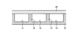
- FIG. 1 is a partial cross-sectional view showing the structure of a plate with a flow path according to an embodiment of the present invention.
- FIG. 2 is an enlarged cross-sectional view of the region R shown in FIG.
- FIG. 3 is a cross-sectional view illustrating a method for manufacturing a plate with a flow path according to an embodiment of the present invention.
- FIG. 4 is a cross-sectional view illustrating a method of manufacturing a plate with a flow channel according to an embodiment of the present invention.
- FIG. 5 is a figure explaining the structure of the test piece used for the Example of this invention.
- FIG. 6A is a diagram showing an SEM image of an interface after joining in an example of the present invention.
- FIG. 6A is a diagram showing an SEM image of an interface after joining in an example of the present invention.
- FIG. 6B is a diagram showing an SEM image of the interface after joining in the example of the present invention.
- FIG. 6C is a diagram showing an SEM image of an interface after joining in an example of the present invention.
- FIG. 7A is a diagram showing an EDX observation image of the interface after joining in the example of the present invention.
- FIG. 7B is a diagram showing an EDX observation image of the interface after joining in the example of the present invention.
- FIG. 7C is a diagram showing an EDX observation image of the interface after joining in the example of the present invention.
- FIG. 7D is a diagram showing an EDX observation image of the interface after joining in the example of the present invention.
- FIG. 7A is a diagram showing an EDX observation image of the interface after joining in the example of the present invention.
- FIG. 7B is a diagram showing an EDX observation image of the interface after joining in the example of the present invention.
- FIG. 7C is a diagram showing an EDX observation image of the interface
- FIG. 8 is a figure which shows the tensile test result of the test piece which carried out the diffusion bonding by making joining surface pressure 0.7 MPa.
- FIG. 9 is a diagram showing a tensile test result of a test piece diffusion-bonded with a bonding surface pressure of 0.7 MPa.
- FIG. 10 is a diagram showing a tensile test result of a test piece diffusion-bonded with a bonding surface pressure of 0.5 MPa.
- FIG. 11 is a diagram showing a tensile test result of a test piece diffusion-bonded with a bonding surface pressure of 0.5 MPa.
- FIG. 12 is a diagram showing an ultrasonic flaw detection test result of the plate with flow passages according to the example.
- FIG. 13 is a diagram for explaining particle measurement.
- FIG. 1 is a partial cross-sectional view showing the structure of a plate with a flow channel according to an embodiment of the present invention.
- FIG. 2 is an enlarged cross-sectional view of the region R shown in FIG.
- the flow path plate 1 shown in FIG. 1 includes a disk-shaped main body 10 and a cover 20 that covers one surface (here, the upper surface) of the main body 10.
- the flow path plate 1 is a bonded body in which the main body 10 and the cover 20 are bonded by diffusion bonding.
- the flow path plate 1 is attached to, for example, a semiconductor device and functions as a cooling device in the semiconductor device.
- the flow path plate 1 may be used as a heater for warming an attached device, or may be used as a heater plate for allowing gas to flow in a flow path described later, and ejects process gas in a thin film forming apparatus. It may be used as a shower head.
- the main body 10 has a disk shape made of aluminum or an aluminum alloy.
- Flow paths (for example, flow paths 11 to 13 shown in FIG. 1) through which a medium that promotes heat exchange is circulated are formed in the main body portion 10.
- the surface of the main body 10 on the opening side of the flow path is joined to the cover 20 by diffusion joining.
- the channels 11 to 13 are separated by the wall portion 14 or the wall portion 15.
- the flow paths 11 to 13 may communicate with each other to form one flow path, or at least a part thereof may form an independent flow path.
- the medium is a liquid such as water or a gas.
- the cover 20 has a disc shape made of aluminum or an aluminum alloy.
- the cover 20 covers the flow path forming surface of the main body 10.
- Examples of the aluminum alloy include No. 6061 aluminum alloy (A6061).
- the main body 10 and the cover 20 are joined by diffusion joining described later.
- the medium is introduced from the medium inlet (not shown) to flow in the flow passage, and the medium is discharged from the medium outlet (not shown).
- the heat transferred from the heat source is released to the outside via the main body 10 and the cover 20, or the medium absorbing the heat transferred from the heat source is discharged from the flow path.
- 3 and 4 are cross-sectional views illustrating a method of manufacturing a plate with flow passages according to an embodiment of the present invention.
- the flow path plate 1 is, for example, in the shape of a disk having a diameter of 150 mm or more.
- the main body 10 and the base material 200 for the cover are joined by diffusion joining (see FIG. 4: diffusion joining step).
- diffusion bonding pressure is applied to the closely attached members under a temperature condition equal to or lower than the melting point of the members, and the diffusion is used to bond the atoms between the bonding surfaces. At this time, a load is applied to the closely attached members to the extent that plastic deformation does not occur as much as possible.
- a joining temperature is 500° C. or more and 640° C. or less, and a joining surface pressure is 0.7 MPa or more.
- the joining temperature varies depending on the type of aluminum alloy. For example, the temperature is set lower than the melting point of the member.
- the bonding surface pressure is preferably 3 MPa or less, though it depends on the kind of the member.
- the flatness of the joint surface of each member is preferably 0.2 or less.
- the surface roughness of the joint surface is preferably greater than 0 and Ra 0.4 or less, and more preferably Ra 0.1 or less.
- the main body 10 and the cover 20 are joined by diffusion joining.
- diffusion bonding it is possible to reliably bond the main body portion and the cover while suppressing deterioration of quality due to the bonding.
- the surface of the flow path is roughened, the flow rate varies in the portion where the brazing material stays, and the temperature changes due to the flow rate variation. It is possible to suppress deterioration of quality such as contamination of impurities due to a brazing material component, and reliably bond the members.
- the present invention may include various embodiments and the like not described here, and various design changes and the like may be made without departing from the technical idea specified by the claims. Is possible.
- FIG. 5 is a figure explaining the structure of the test piece used for the Example of this invention.
- the member 300 is made of No. 6061 aluminum alloy (A6061).
- the member 300 has a substantially columnar joint portion 301 having a joint surface, and a grip portion 302 which is continuous with the joint surface side of the joint portion 301 and which is gripped during a test.
- the grip 302 has a thread formed on its side surface.
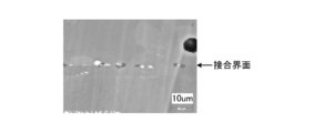
- FIGS. 6A to 6C are views showing SEM images of the interface after joining in the example of the present invention.
- FIG. 6B is an enlarged view of the central portion of FIG. 6A.
- FIG. 6C is an enlarged view of the central portion of FIG. 6B. As shown in FIGS. 6A to 6C, it can be seen that the bonding is performed without defects at the bonding interface.
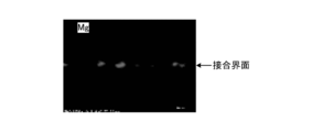
- FIG. 7A to 7D are diagrams showing EDX observation images of the interface after joining in the example of the present invention.
- FIG. 7A shows a reflection image at the interface after joining.
- FIG. 7B shows a distribution image of aluminum (Al) at the interface after joining.
- FIG. 7C shows a distribution image of magnesium (Mg) at the interface after joining.
- FIG. 7D shows a distribution image of silicon (Si) at the interface after bonding. 7B to 7D, the lighter the color, the more the component is included.
- FIG. 7B it can be seen that aluminum, which is the main component of the member 300, is widely distributed. Further, as shown in FIGS. 7C and 7D, it can be seen that magnesium and silicon are precipitated at the bonding interface. Here, magnesium and silicon reduce the oxide film of aluminum to an oxide. It is considered that this reaction causes the amorphous oxide film at the bonding interface to change to crystalline oxide particles, which contributes to bonding between the members 300.
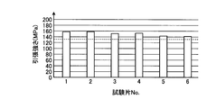
- FIG. 8 is a diagram showing a tensile test result of a test piece diffusion-bonded with a bonding surface pressure of 0.7 MPa.
- Test piece No. 1 to No. No. 6 has a tensile strength of more than 125 MPa.
- the tensile strength of No. 6061 aluminum alloy (A6061) is 125 MPa. From this, the test piece No. 1 to No. No. 6 can be said to have a tensile strength that is greater than the tensile strength of the No. 6061 aluminum alloy (A6061) that is the main component of the member 300.
- FIG. 9 is a diagram showing a tensile test result of a test piece diffusion-bonded with a bonding surface pressure of 0.7 MPa. Test piece No. 1 to No. It can be seen that in all of No. 6, the fracture occurred in one member, not in the bonded interface.
- FIG. 10 is a diagram showing a tensile test result of a test piece diffusion-bonded with a bonding surface pressure of 0.5 MPa.
- Test piece No. 11-No. In No. 16 the test piece No. The tensile strength of No. 13 is less than 125 MPa. From this, the test piece No. 11-No. In some cases, 16 has a tensile strength smaller than the tensile strength of the No. 6061 aluminum alloy (A6061) which is the main component of the member 300.
- A6061 aluminum alloy
- FIG. 11 is a diagram showing a tensile test result of a test piece diffusion-bonded with a bonding surface pressure of 0.5 MPa. Test piece No. 11-No. It can be seen that some of 16 (test pieces No. 13 and No. 16) are fractured at the bonding interface.
- FIG. 12 is a diagram showing an ultrasonic flaw detection test result of the plate with flow passages according to the example.
- FIG. 12 shows a plate with a flow channel bonded with a bonding surface pressure of 0.7 MPa. As can be seen from FIG. 12, there is no defect such as damage in the flow path formed in the disk member.
- FIG. 13 is a diagram for explaining particle measurement.
- each test piece (test piece 100) was attached to the jig 101, and particles collected via the jig 101 were measured by the measuring device 102. Particle measurement was carried out three times for each test piece. Since the amount of initial particles is large, in the first measurement, the process of flowing nitrogen into the flow channel was carried out several times for several minutes to stabilize the particles, and then the particles were measured.
- IPA isopropyl alcohol
- nitrogen was introduced for 1 minute, and the number of particles (accumulated number) according to the particle diameter was counted.
- the number of particles having a particle size (particle size) of 0.3 ⁇ m or less and the number of particles having a particle size of more than 0.3 ⁇ m and 0.5 ⁇ m or less were counted.
- the results of particle measurement by the test pieces joined by diffusion joining are as follows. Particle size 0.5 ⁇ m or less 0.3 ⁇ m or less First time 88 15 Second time 39 13 Third time 15 2
- the results of particle measurement by the test pieces joined by brazing are as follows. Particle size 0.3 ⁇ m or less 0.5 ⁇ m or less First time 483 168 Second time 238 84 Third time 189 87
- the count number was zero in all sizes. From the above measurement results, it can be said that the flow channels of the plate with flow channels joined by diffusion bonding have less particles than the flow channels of the plate with flow channels joined by brazing.
- the joining method and the joined body according to the present invention are suitable for surely joining the main body and the cover and suppressing the quality deterioration due to the joining.
Abstract
Description
アルミニウム合金としては、例えば6061番のアルミニウム合金(A6061)が挙げられる。
本体部10とカバー20とは、後述する拡散接合によって接合される。 The
Examples of the aluminum alloy include No. 6061 aluminum alloy (A6061).
The
接合温度は、アルミニウム合金の種類によって変わる。例えば、部材の融点よりも低い温度に設定される。
接合面圧は、部材の種類にもよるが、3MPa以下であることが好ましい。
また、各部材の接合面の精度として、平面度が0.2以下であることが好ましい。また、接合面の面粗度は、0より大きくRa0.4以下であることが好ましく、Ra0.1以下であることがさらに好ましい。 As conditions for diffusing and joining members made of aluminum or aluminum alloy, a joining temperature is 500° C. or more and 640° C. or less, and a joining surface pressure is 0.7 MPa or more.
The joining temperature varies depending on the type of aluminum alloy. For example, the temperature is set lower than the melting point of the member.
The bonding surface pressure is preferably 3 MPa or less, though it depends on the kind of the member.
Further, the flatness of the joint surface of each member is preferably 0.2 or less. The surface roughness of the joint surface is preferably greater than 0 and Ra 0.4 or less, and more preferably Ra 0.1 or less.
接合体として試験を行う試験片は、同一の形状をなす二つの部材を接合させたものを使用した。図5は、本発明の実施例に用いた試験片の構成を説明する図である。本試験片は、部材300を拡散接合させたものを使用した。部材300は、6061番のアルミニウム合金(A6061)からなる。部材300は、接合面を有する略円柱状の接合部301と、接合部301の接合面側と反対側に連なり、試験時に把持される把持部302とを有する。把持部302は、側面においてねじ山が形成されている。 (Evaluation of joint surface of test piece)
As a test piece to be tested as a bonded body, one in which two members having the same shape were bonded was used. FIG. 5: is a figure explaining the structure of the test piece used for the Example of this invention. As the present test piece, the one obtained by diffusion-bonding the
また、図7Cおよび図7Dに示すように、マグネシウムやケイ素が接合界面において析出していることがわかる。ここでは、マグネシウムやケイ素が、アルミニウムの酸化皮膜を還元して酸化物となる。この反応によって、接合界面の非晶質酸化膜が結晶酸化物粒子に変化し、部材300同士の接合に寄与していることが考えられる。 As shown in FIG. 7B, it can be seen that aluminum, which is the main component of the
Further, as shown in FIGS. 7C and 7D, it can be seen that magnesium and silicon are precipitated at the bonding interface. Here, magnesium and silicon reduce the oxide film of aluminum to an oxide. It is considered that this reaction causes the amorphous oxide film at the bonding interface to change to crystalline oxide particles, which contributes to bonding between the
また、これらの試験片について、引張試験を実施した。接合面圧を0.7MPaとして接合した試験片にNo.1~No.6の番号を付し、接合面圧を0.5MPaとして接合した試験片にNo.11~No.16の番号を付して試験を行った。引張試験結果を、図8~図11に示す。 (Tensile test of test piece)
A tensile test was performed on these test pieces. No. was applied to the test piece bonded with the bonding surface pressure set to 0.7 MPa. 1 to No. No. 6 was added to the test piece bonded with the bonding surface pressure of 0.5 MPa. 11-No. The test was carried out by numbering 16. The tensile test results are shown in FIGS. 8 to 11.
図12は、実施例にかかる流路付きプレートの超音波探傷試験結果を示す図である。図12は、接合面圧を0.7MPaとして接合した流路付きプレートを示している。図12から分かるように、円板の部材に形成されている流路に損傷などの欠陥がないことがわかる。 (Ultrasonic flaw testing of plate with flow path)
FIG. 12 is a diagram showing an ultrasonic flaw detection test result of the plate with flow passages according to the example. FIG. 12 shows a plate with a flow channel bonded with a bonding surface pressure of 0.7 MPa. As can be seen from FIG. 12, there is no defect such as damage in the flow path formed in the disk member.
また、上述した流路付きプレート1を作製し、この流路付きプレート1を試験片として、パーティクル測定を行った。比較対象として、ろう付によって接合した試験片を作製して、パーティクル測定を行った。図13は、パーティクル測定について説明する図である。本実施例では、各試験片(試験片100)を治具101に取り付け、治具101を介して収集したパーティクルを、測定器102によって測定した。パーティクル測定は、各試験片について、それぞれ三回実施した。
初期のパーティクルは量が多いため、一回目の測定では、数分間、流路に窒素を流す処理を複数回実施し、パーティクルを安定させてからパーティクルの測定を行った。パーティクル測定では、まず、イソプロピルアルコール(Isopropyl alcohol:IPA)を流路に導入し、45秒間、窒素でブローした。その後、窒素を1分導入し、粒径に応じた粒子数(積算数)をカウントした。本実施例では、粒径(パーティクルサイズ)が0.3μm以下の粒子数と、粒径が0.3μmより大きく0.5μm以下の粒子数をカウントした。 (Particle measurement of plate with flow path)
In addition, the above-described
Since the amount of initial particles is large, in the first measurement, the process of flowing nitrogen into the flow channel was carried out several times for several minutes to stabilize the particles, and then the particles were measured. In the particle measurement, first, isopropyl alcohol (IPA) was introduced into the flow channel and blown with nitrogen for 45 seconds. Then, nitrogen was introduced for 1 minute, and the number of particles (accumulated number) according to the particle diameter was counted. In this example, the number of particles having a particle size (particle size) of 0.3 μm or less and the number of particles having a particle size of more than 0.3 μm and 0.5 μm or less were counted.
パーティクルサイズ
0.5μm以下 0.3μm以下
1回目 88 15
2回目 39 13
3回目 15 2
これに対し、ろう付けによって接合した試験片によるパーティクル測定の結果は、以下のようになった。
パーティクルサイズ
0.3μm以下 0.5μm以下
1回目 483 168
2回目 238 84
3回目 189 87
なお、治具のみのパーティクル測定では、いずれのサイズもカウント数がゼロであった。
上述した測定結果から、拡散接合によって接合した流路付きプレートの流路は、ろう付によって接合した流路付きプレートの流路と比して、パーティクルが少ないといえる。 The results of particle measurement by the test pieces joined by diffusion joining are as follows.
Particle size 0.5 μm or less 0.3 μm or less First time 88 15
Second time 39 13
On the other hand, the results of particle measurement by the test pieces joined by brazing are as follows.
Particle size 0.3 μm or less 0.5 μm or less First time 483 168
Second time 238 84
Third time 189 87
In addition, in the particle measurement of only the jig, the count number was zero in all sizes.
From the above measurement results, it can be said that the flow channels of the plate with flow channels joined by diffusion bonding have less particles than the flow channels of the plate with flow channels joined by brazing.
10 本体部
11~13 流路
14、15 壁部
20 カバー DESCRIPTION OF
Claims (5)
- アルミニウムまたはアルミニウム合金からなり、熱交換を促す媒体を流通させる流路が形成される本体部と、アルミニウムまたはアルミニウム合金からなり、前記本体部の前記流路を覆うカバーとを接合する接合方法であって、
前記本体部に前記カバーを被せる被覆ステップと、
接合温度が500℃以上640℃以下、接合面圧が0.7MPa以上の条件下で拡散接合することによって、前記本体部と前記カバーとを接合する拡散接合ステップと、
を含むことを特徴とする接合方法。 A joining method of joining a main body part made of aluminum or an aluminum alloy, in which a flow path through which a medium for promoting heat exchange is formed, and a cover made of aluminum or aluminum alloy and covering the flow path of the main body part. hand,
A covering step of covering the body with the cover,
A diffusion bonding step of bonding the main body part and the cover by diffusion bonding under a bonding temperature of 500° C. or more and 640° C. or less and a bonding surface pressure of 0.7 MPa or more;
A joining method comprising: - 前記本体部の接合面および前記カバーの接合面の平面度が、それぞれ0.2以下である
ことを特徴とする請求項1に記載の接合方法。 The flatness of the joint surface of the main body part and the flatness of the joint surface of the cover are each 0.2 or less. - 前記本体部の接合面および前記カバーの接合面の面粗度が、各々0より大きくRa0.4以下である
ことを特徴とする請求項1または2に記載の接合方法。 The surface roughness of the joint surface of the main body part and the surface roughness of the joint surface of the cover are both greater than 0 and not more than Ra 0.4, respectively. - アルミニウムまたはアルミニウム合金からなり、熱交換を促す媒体を流通させる流路が形成される本体部と、
アルミニウムまたはアルミニウム合金からなり、前記本体部の前記流路を覆うカバーと、
を備え、
前記本体部と前記カバーとが、拡散接合されてなる
ことを特徴とする接合体。 A main body made of aluminum or an aluminum alloy, in which a flow path is formed for circulating a medium that promotes heat exchange,
A cover made of aluminum or aluminum alloy, which covers the flow path of the main body portion,
Equipped with
A joined body, wherein the main body portion and the cover are diffusion-joined. - 前記本体部および前記カバーが、6061番のアルミニウム合金からなり、
引張り強さが125MPa以上である
ことを特徴とする請求項4に記載の接合体。 The main body and the cover are made of No. 6061 aluminum alloy,
Tensile strength is 125 MPa or more. The joined body according to claim 4, wherein the joined body has a tensile strength of 125 MPa or more.
Priority Applications (5)
| Application Number | Priority Date | Filing Date | Title |
|---|---|---|---|
| JP2020561389A JPWO2020129863A1 (en) | 2018-12-21 | 2019-12-13 | Joining method and joining body |
| CN201980084269.3A CN113195146A (en) | 2018-12-21 | 2019-12-13 | Bonding method and bonded body |
| US17/413,680 US20220009022A1 (en) | 2018-12-21 | 2019-12-13 | Joining method and joined body |
| EP19900978.8A EP3900867A4 (en) | 2018-12-21 | 2019-12-13 | Joining method and joint body |
| KR1020217017680A KR20210089732A (en) | 2018-12-21 | 2019-12-13 | Bonding method and conjugate |
Applications Claiming Priority (2)
| Application Number | Priority Date | Filing Date | Title |
|---|---|---|---|
| JP2018-240266 | 2018-12-21 | ||
| JP2018240266 | 2018-12-21 |
Publications (1)
| Publication Number | Publication Date |
|---|---|
| WO2020129863A1 true WO2020129863A1 (en) | 2020-06-25 |
Family
ID=71101298
Family Applications (1)
| Application Number | Title | Priority Date | Filing Date |
|---|---|---|---|
| PCT/JP2019/049049 WO2020129863A1 (en) | 2018-12-21 | 2019-12-13 | Joining method and joint body |
Country Status (6)
| Country | Link |
|---|---|
| US (1) | US20220009022A1 (en) |
| EP (1) | EP3900867A4 (en) |
| JP (1) | JPWO2020129863A1 (en) |
| KR (1) | KR20210089732A (en) |
| CN (1) | CN113195146A (en) |
| WO (1) | WO2020129863A1 (en) |
Citations (4)
| Publication number | Priority date | Publication date | Assignee | Title |
|---|---|---|---|---|
| JP2004216242A (en) * | 2003-01-14 | 2004-08-05 | Nippon Steel Corp | Heat resistant stainless steel foil for metal carrier for waste gas purification having satisfactory diffusion joinability, and metal carrier |
| JP2006159223A (en) * | 2004-12-03 | 2006-06-22 | Kobelco Kaken:Kk | METHOD FOR PRODUCING Al OR Al ALLOY JOINED BODY |
| JP2009535801A (en) | 2006-04-28 | 2009-10-01 | ダンスン エレクトロン カンパニー リミテッド | Manufacturing method of susceptor and susceptor manufactured by this method |
| JP2014091125A (en) * | 2012-10-31 | 2014-05-19 | Nitto Seiko Co Ltd | Steel component different in carbon content and method of manufacturing the same |
Family Cites Families (32)
| Publication number | Priority date | Publication date | Assignee | Title |
|---|---|---|---|---|
| JPS5461015A (en) * | 1977-10-25 | 1979-05-17 | Kobe Steel Ltd | Manufacture of aluminum-soldered fin heat exchanger |
| GB8429979D0 (en) * | 1984-11-28 | 1985-02-13 | British Aerospace | Diffusion banding of metals |
| JPS62254989A (en) * | 1986-04-24 | 1987-11-06 | セジユデユ−ル・ソシエテ・ドウ・トランスフオルマシオン・ドウ・ラリユミニウム・ペシネ | Connection of aluminum or aluminum alloy member by solid state diffusion |
| US5433835B1 (en) * | 1993-11-24 | 1997-05-20 | Applied Materials Inc | Sputtering device and target with cover to hold cooling fluid |
| JP2001050682A (en) * | 1999-08-05 | 2001-02-23 | Showa Alum Corp | Panel-type heat exchanger, and manufacture thereof |
| JP2003300391A (en) * | 2002-04-08 | 2003-10-21 | Sumitomo Electric Ind Ltd | Joined body for heat contact-bonding and heat contact- bonding device using the joined body |
| DE10251658B4 (en) * | 2002-11-01 | 2005-08-25 | Atotech Deutschland Gmbh | Method for connecting microstructured component layers suitable for the production of microstructure components and microstructured component |
| CN1234496C (en) * | 2002-12-27 | 2006-01-04 | 北京青云航空仪表有限公司 | Low temp. and low pressure reaction type diffusion welding for aluminium and copper sheets |
| JP2005021946A (en) * | 2003-07-03 | 2005-01-27 | Masao Hondo | Joining method for different metal member |
| JP4838992B2 (en) * | 2004-10-08 | 2011-12-14 | 古河スカイ株式会社 | Heater plate and heater plate manufacturing method |
| JP2007285682A (en) * | 2006-04-20 | 2007-11-01 | Xenesys Inc | Heat exchanger manufacturing method |
| JP5411136B2 (en) * | 2008-07-15 | 2014-02-12 | 東京エレクトロン株式会社 | Microwave plasma processing apparatus and cooling jacket manufacturing method |
| JP2010094683A (en) * | 2008-10-14 | 2010-04-30 | Panasonic Corp | Diffusion bonding method of aluminum alloy |
| US8159821B2 (en) * | 2009-07-28 | 2012-04-17 | Dsem Holdings Sdn. Bhd. | Diffusion bonding circuit submount directly to vapor chamber |
| WO2011152556A1 (en) * | 2010-06-04 | 2011-12-08 | 古河スカイ株式会社 | Method of joining aluminum alloys |
| KR20120021770A (en) * | 2010-08-17 | 2012-03-09 | 명화공업주식회사 | Ultralight dual drum brake and manufacturing method thereof |
| CN103722304B (en) * | 2014-01-09 | 2016-12-07 | 北京航空航天大学 | A kind of aluminium alloy interface low temperature diffusion connection material for interface enhancing heat transfer |
| CN104084691A (en) * | 2014-07-10 | 2014-10-08 | 西北工业大学 | Aluminum alloy constant-strength diffusion connecting method |
| FR3026974B1 (en) * | 2014-10-10 | 2016-12-09 | Commissariat Energie Atomique | METHOD OF MAKING A HEAT EXCHANGER MODULE WITH AT LEAST TWO FLUID CIRCUIT CIRCUITS, THERMAL EXCHANGER AND REACTOR-EXCHANGER THEREFOR |
| WO2016138987A1 (en) * | 2015-03-02 | 2016-09-09 | Linde Aktiengesellschaft | Method for producing a plate heat exchanger |
| JP6468028B2 (en) * | 2015-03-30 | 2019-02-13 | 三菱マテリアル株式会社 | Power module board with heat sink |
| JP6808503B2 (en) * | 2016-02-05 | 2021-01-06 | 株式会社アルバック | Member joining method |
| JP6572810B2 (en) * | 2016-03-15 | 2019-09-11 | 三菱マテリアル株式会社 | Manufacturing method of joined body and manufacturing method of power module substrate |
| JP6321067B2 (en) * | 2016-03-31 | 2018-05-09 | 住友精密工業株式会社 | Diffusion bonding type heat exchanger |
| CN106475679B (en) * | 2016-11-30 | 2018-07-27 | 山东大学 | A kind of discontinuous pressure process diffusion connecting process of unrepeatered transmission of copper and aluminium alloy |
| US11289400B2 (en) * | 2018-03-26 | 2022-03-29 | Mitsubishi Materials Corporation | Method of manufacturing bonded body for insulation circuit substrate board and bonded body for insulation circuit substrate board |
| CN108161324A (en) * | 2018-03-30 | 2018-06-15 | 吉林大学 | Aluminium alloy heat dissipation cold plate spreads welding clamp |
| GB2573546B (en) * | 2018-05-09 | 2021-03-31 | Twi Ltd | A method of diffusion bonding |
| DE102019204131A1 (en) * | 2019-03-26 | 2019-06-06 | Carl Zeiss Smt Gmbh | Device for guiding a liquid or gaseous medium, method for producing a corresponding device, field facet module and projection exposure apparatus |
| CN110253131B (en) * | 2019-07-01 | 2020-12-04 | 中国科学院工程热物理研究所 | Capillary channel heat exchanger and preparation method thereof |
| CN110375567A (en) * | 2019-07-20 | 2019-10-25 | 中国船舶重工集团公司第七二四研究所 | A kind of multilevel access cold plate and its manufacturing process based on lamination diffusion welding craft |
| CN110579123A (en) * | 2019-09-19 | 2019-12-17 | 中国核动力研究设计院 | High-pressure compact heat exchanger structure with double-side special-shaped runners and assembling method thereof |
-
2019
- 2019-12-13 KR KR1020217017680A patent/KR20210089732A/en active IP Right Grant
- 2019-12-13 JP JP2020561389A patent/JPWO2020129863A1/en active Pending
- 2019-12-13 CN CN201980084269.3A patent/CN113195146A/en active Pending
- 2019-12-13 EP EP19900978.8A patent/EP3900867A4/en active Pending
- 2019-12-13 WO PCT/JP2019/049049 patent/WO2020129863A1/en active Search and Examination
- 2019-12-13 US US17/413,680 patent/US20220009022A1/en active Pending
Patent Citations (4)
| Publication number | Priority date | Publication date | Assignee | Title |
|---|---|---|---|---|
| JP2004216242A (en) * | 2003-01-14 | 2004-08-05 | Nippon Steel Corp | Heat resistant stainless steel foil for metal carrier for waste gas purification having satisfactory diffusion joinability, and metal carrier |
| JP2006159223A (en) * | 2004-12-03 | 2006-06-22 | Kobelco Kaken:Kk | METHOD FOR PRODUCING Al OR Al ALLOY JOINED BODY |
| JP2009535801A (en) | 2006-04-28 | 2009-10-01 | ダンスン エレクトロン カンパニー リミテッド | Manufacturing method of susceptor and susceptor manufactured by this method |
| JP2014091125A (en) * | 2012-10-31 | 2014-05-19 | Nitto Seiko Co Ltd | Steel component different in carbon content and method of manufacturing the same |
Non-Patent Citations (1)
| Title |
|---|
| See also references of EP3900867A4 |
Also Published As
| Publication number | Publication date |
|---|---|
| KR20210089732A (en) | 2021-07-16 |
| JPWO2020129863A1 (en) | 2021-11-25 |
| TW202023722A (en) | 2020-07-01 |
| EP3900867A4 (en) | 2022-09-28 |
| CN113195146A (en) | 2021-07-30 |
| EP3900867A1 (en) | 2021-10-27 |
| US20220009022A1 (en) | 2022-01-13 |
Similar Documents
| Publication | Publication Date | Title |
|---|---|---|
| US11091397B2 (en) | Low temperature method for hermetically joining non-diffusing ceramic materials in multi-layer plate devices | |
| US20190076948A1 (en) | Welded, Laminated Apparatus, Methods of Making, and Methods of Using the Apparatus | |
| JP4257728B2 (en) | Formation method of spatter target assembly | |
| US7432474B2 (en) | Heating device | |
| JP6231428B2 (en) | Li-containing oxide target bonded body and manufacturing method thereof | |
| CN107735386A (en) | Method for repairing the equipment parts used in semiconductor machining | |
| JP7312825B2 (en) | Beryllium-copper alloy joined body and manufacturing method thereof | |
| WO2020129863A1 (en) | Joining method and joint body | |
| JP2009291793A (en) | Method for producing structure | |
| TWI830840B (en) | Joining method and joining body | |
| JPS59225893A (en) | Joining method of ti or ti alloy to al or al alloy | |
| JPH07218670A (en) | Preparation of cooler | |
| Zhao et al. | Influence of surface morphology on wetting behaviors of liquid metal during aluminum heat exchanger fabrication | |
| US6779713B1 (en) | Joining of composite beryllium-aluminum parts | |
| WO2020022046A1 (en) | Method for brazing alumina dispersion strengthened copper | |
| TW202030830A (en) | Bonding component, bonding component for semiconductor manufacturing process and semiconductor manufacturing process device | |
| JP2020015046A (en) | Brazing joining method for alumina dispersion strengthened copper | |
| Parise et al. | Development of diffusion bonded joints of AA6061 aluminum alloy to AISI 316LN stainless steel for sirius planar undulators | |
| JP3976993B2 (en) | Ceramic substrate bonding method, ceramic substrate bonded body, and ceramic heater | |
| JP6318441B2 (en) | Joining method | |
| JP6502225B2 (en) | Ceramic heater and method of manufacturing the same | |
| TW202100269A (en) | Bonding component and method of making the same | |
| JP2023044704A (en) | Holding member and manufacturing method thereof | |
| TW202307238A (en) | Sputtering target and method for producing sputtering target | |
| TW202333285A (en) | Electrostatic chuck and related methods and structures |
Legal Events
| Date | Code | Title | Description |
|---|---|---|---|
| 121 | Ep: the epo has been informed by wipo that ep was designated in this application |
Ref document number: 19900978 Country of ref document: EP Kind code of ref document: A1 |
|
| DPE1 | Request for preliminary examination filed after expiration of 19th month from priority date (pct application filed from 20040101) | ||
| ENP | Entry into the national phase |
Ref document number: 2020561389 Country of ref document: JP Kind code of ref document: A |
|
| ENP | Entry into the national phase |
Ref document number: 20217017680 Country of ref document: KR Kind code of ref document: A |
|
| NENP | Non-entry into the national phase |
Ref country code: DE |
|
| ENP | Entry into the national phase |
Ref document number: 2019900978 Country of ref document: EP Effective date: 20210721 |